unit – iii - generator protection &transformer protection ...€¦ · rotor earth fault...
TRANSCRIPT

Unit – III - Generator Protection &Transformer Protection
GENERATOR PROTECTION
Merz-price Differential protection:
In merz-price differential protection the primaries of the CTs are connected in series on
the both side of each phase winding of the generator. The secondaries of the CTs are connected
in additive manner to pass the circulating currents through a closed path. The differential relay
constantly checks on the secondary sides of CTs as to whether the incoming current of a phase
winding is equal to the respective outgoing current of the same winding.
The directions of currents passing through the secondary side of the CTs are shown in fig.
If the currents on the primary sides , that is, IA1 and IA2, have the same magnitude, then the
secondary side currents, ia1 and ia2 will also have the same magnitude, considering that CTs on
both sides have same turns ratio and have identical characteristics. If there is a significant
difference in currents (Id) on both sides of the windings, then this indicates a fault in the
protection zone of the stator winding of the generator. Hence the differential relay trips if the
value of Id exceeds a predetermined value (relay setting). On the other hand, during external
faults, the differential relay remains stable and does not initiate a trip signal.
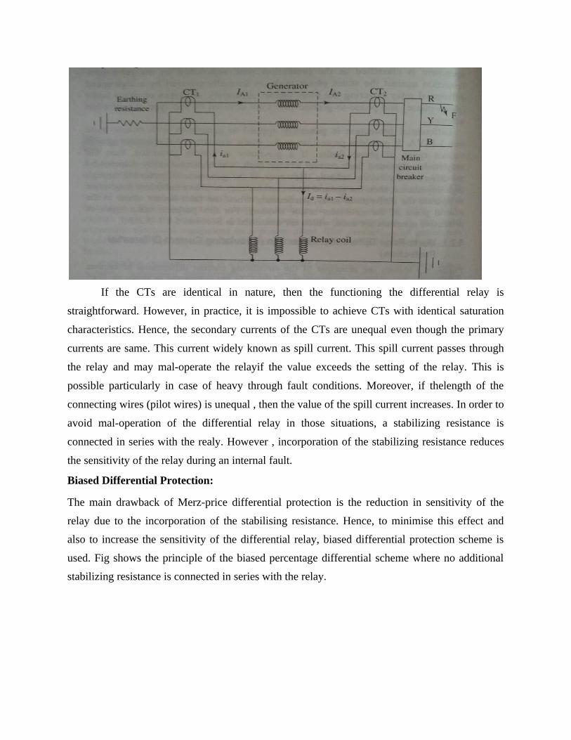
If the CTs are identical in nature, then the functioning the differential relay is
straightforward. However, in practice, it is impossible to achieve CTs with identical saturation
characteristics. Hence, the secondary currents of the CTs are unequal even though the primary
currents are same. This current widely known as spill current. This spill current passes through
the relay and may mal-operate the relayif the value exceeds the setting of the relay. This is
possible particularly in case of heavy through fault conditions. Moreover, if thelength of the
connecting wires (pilot wires) is unequal , then the value of the spill current increases. In order to
avoid mal-operation of the differential relay in those situations, a stabilizing resistance is
connected in series with the realy. However , incorporation of the stabilizing resistance reduces
the sensitivity of the relay during an internal fault.
Biased Differential Protection:
The main drawback of Merz-price differential protection is the reduction in sensitivity of the
relay due to the incorporation of the stabilising resistance. Hence, to minimise this effect and
also to increase the sensitivity of the differential relay, biased differential protection scheme is
used. Fig shows the principle of the biased percentage differential scheme where no additional
stabilizing resistance is connected in series with the relay.

The biased percentage differential relay has 2 settings namely basic setting and
bias setting. Basic setting is the difference between two CT secondary currents (i1-i2). Bias
setting is the ratio of the difference between two CT secondary currents to the average values of
two currents ().In the case of a normal condition or external fault condition some amount of spill
current (i1-i2) is already available because of the non-identical CTs and un equal lead length.
However at the same time average value also increases hence fault current will not cross the bias
setting of the relay even though the basic setting is exceeded therefore mal-operation of the relay
can be avoided.
On the other hand during an internal fault two currents on the primary sides of the
CTs become unequal a spill current (i1-i2) is produced on the secondary side of the 2 CTs this
crosses not only the basic setting limit of the relay but also the bias setting limit because of the
increase in spill current and decrease in the average of the two currents. Finally the relay
operates and trips the generator as per the requirement. The fundamental advantage of this
scheme is that it makes the scheme more permissive towards CT mis-match, thus reducing the
relays sensitivity to external faults. More over it provides more sensitivity in case of internal
faults.

Rotor Earth Fault Protection:
The rotor circuit of the alternator is not earthed and d.c. voltage is imposed on it. And hence
single ground fault in rotor does not cause circulating current to flow through the rotor circuit.
Hence single ground fault in rotor does not cause any damage to it. But single ground fault
causes an increase in the stress to ground at other points in the field winding when voltages are
induced in the rotor due to transients. Thus the probability of second ground fault increases.
If the second ground fault occurs then part of the rotor winding is bypassed and the currents
in the remaining portion increases abruptly. This causes the unbalance of rotor circuit and hence
the mechanical and thermal stresses on the rotor. Due to this, rotor may get damaged. Sometimes
damage of bearings and bending of rotor shaft take place due to the vibrations. Hence the rotor
must be protected against earth fault.
The modern method of providing earth fault protection includes d.c. injection or a.c.
injection. The scheme is shown in the Fig.
A small DC power supply is connected to the field circuit. A fault detecting sensitive relay and
the resistance are also connected in series with the circuit. This high resistance limits the current
through the circuit.
A fault at any point on the field circuit will pass a current of sufficient magnitude through
the relay to cause its operation. The d.c. supply is preferred and simple to use and it has no
problem of the leakage currents. In case of a.c. injection, the high resistance is replaced by a
capacitor.

The earth fault relays are instantaneous in operation and are connected to an alarm circuit for
indication and to take the proper action. This is because; a single ground fault does not require an
immediate action of isolating the generator.
Restricted Earth Fault Protection:
When the neutral is solidly grounded, it is possible to provide protection to complete winding
of the generator against ground faults. However, the neutral is grounded through resistance to limit
ground fault currents. With resistance grounding it is not possible to protect the complete winding
against ground faults. The percentage of winding protected depends on the value of the neutral
grounding resistor and the relay setting. The usual practice is to protect 80 to 85% of the generator
winding against ground fault. The remaining 15-20% from neutral end is left unprotected. The relay
setting for the differential protection is determined by the value of the neutral grounding resistor and
the percentage of winding to be protected. If the ground fault occurs at the point F of the generator
winding, the voltage VFN is available to drive the ground-fault current If through the neutral to
ground connection. If the fault point F is nearer to the neutral point N, the forcing voltage V FN, will
be relatively less. Hence, ground fault current If will reduce. It is not practicable to keep the relay

setting too sensitive to sense the ground fault currents of small magnitudes. Because, if the relay is
made too sensitive, it may respond during through faults. The percentage of winding that is left
unprotected;
Stator Inter-Turn Protection:Merz-price circulating-current system protects against phase-to-ground and phase-to-
phase faults. It does not protect against turn-to-turn fault on the same phase winding of the stator.

It is because the current that this type of fault produces flows in a local circuit between the turns
involved and does not create a difference between the currents entering and leaving the winding
at its two ends where current transformers are applied. However, it is usually considered
unnecessary to provide protection for inter-turn faults because they invariably develop into earth-
faults.
In single turn generator there is no necessity of protection against inter-turn faults. However,
inter-turn protection is provided for multi-turn generators such as hydro-electric generators.
These generators have double-winding armatures
as they carry very heavy currents. The relays
Rcprovide protection against phase-to-ground and
phase-to-phase faults whereas relays R1 provide
protection against inter-turn faults.
Two current transformers are connected on thecirculating-current principle. Under normal
conditions, the currents in the stator windings S1
and S2 are equal and so will be the currents in
the secondaries of the two CTs. The secondary current round the loop then is the same at all
points and no current flows through the relay RI. If a short-circuit develops between adjacent
turns, say on S1, the currents in the stator windings S1 and S2 will no longer be equal. Therefore,
unequal currents will be induced in the secondaries of CTs and the difference of these two
currents flows through the relay RI. The relay then closes its contacts to clear the generator from
the system.
TRANSFORMER PROTECTION:
Transformers are static devices, totally enclosed and generally oil immersed. Therefore,
chances of faults occurring on them are very rare. However, the consequences of even a rare
fault may be very serious unless the transformer is quickly disconnected from the system. This
necessitates to provide adequate automatic protection for transformers against possible faults.
Small distribution transformers are usually connected to the supply system through series

fuses instead of circuit breakers. Consequently, no automatic protective relay equipment is
required. However, the probability of faults on power transformers is undoubtedly more and
hence automatic protection is absolutely necessary.
Common transformer faults. As compared with generators, in which many abnormalconditions
may arise, power transformers may suffer only from:
(i) Open circuits (ii) Over heating (iii) winding short-circuits e.g. earth-faults, phase-to-
phasefaults and inter-turn faults.
An open circuit in one phase of a 3-phase transformer may cause undesirable heating. In
practice, relay protection is not provided against open circuits because this condition is relatively
harmless. On the occurrence of such a fault, the transformer can be disconnected manually from
the system.
Overheating of the transformer is usually caused by sustained overloads or short-circuits and
very occasionally by the failure of the cooling system. The relay protection is also not provided
against this contingency and thermal accessories are generally used to sound an alarm or control
the banks of fans.
Winding short-circuits (also called internal faults) on the transformer arise from deterioration of
winding insulation due to overheating or mechanical injury. When an internal fault occurs, the
transformer must be disconnected quickly from the system because a prolonged arc in the
transformer may cause oil fire. Therefore, relay protection is absolutely necessary for internal
faults. The principal relays and systems used for transformer protection are:
Buchholz devices providing protection against all kinds of incipient faults i.e. slow
developing faults such as insulation failure of windings, core heating, fall of oil level due to
leaky joints etc.
Earth-fault relays providing protection against earth-faults only.
Over current relays providing protection mainly against phase-to-phase faults and Over
loading.
Differential system (or circulating-current system) providing protection against both earth
and phase faults.
The complete protection of transformer usually requires the combination of these
systems. Choice of a particular combination of systems may depend upon several factors such as (a)
size of the transformer (b) type of cooling (c) location of transformer in the network
(d) nature of load supplied and (e) importance of service for which transformer is required.

Transformer differential protection:
Basic discussions related to the Merz-Price Scheme and its limitations which are taken care
by the biased differential scheme, are omitted for repetition 2.7.1 Basic considerations
a. Transformation ratio
The nominal currents in the primary and secondary sides of the transformer vary in inverse
ratio to the corresponding voltages. This should be compensated for by using different transformation
ratios for the CTs on the primary and secondary sides of the transformer.
b. Current Transformer Connections
When a Transformer is connected in star/delta, the secondary current has a phase shift of
300 relative to the primary
This phase shift can be offset by suitable secondary CT connections
The zero-sequence currents flowing on the star-side of the transformer will not produce
current outside the delta on the other side. The zero sequence current must therefore be eliminated
from the star-side by connecting the CTs in delta.
The CTs on delta side should be connected in star in order to give 300 phase shift. When CTs are connected in delta, their secondary ratings must be reduced to 1/3 times
thesecondary ratings of the star-connected transformer, in order that the currents outside the
delta may balance with the secondary currents of the star-connected CTs.
If transformers were connected in star/star, the CTs on both sides would need be connected in
delta-delta.
c. Bias to cover tap-changing facility and CT mismatch
If the transformer has the benefit of a tap changer, it is possible to vary its transformationratio
for voltage control.
The differential protection system should be able to cope with this variation.
This is because if the CTs are chosen to balance for the mean ratio of the power transformer,
a variation in ratio from the mean will create an unbalance proportional to the ratio change.
At maximum through fault current, the spill output produced by the small percentage
unbalance may be substantial.
Differential protection should be provided with a proportional bias of an amount which
exceeds in effect the maximum ratio deviation. This stabilizes the protection under through
fault conditions while still permitting the system to have good basic sensitivity.
d. Magnetization Inrush

The magnetizing inrush produces a current flow into the primary winding that does not have
any equivalent in the secondary winding. The net effect is thus similar to the situation when
there is an internal fault on the transformer.
Since the differential relay sees the magnetizing current as an internal fault, it is necessary to
have some method of distinguishing between the magnetizing current and the fault current
using one or all of the following methods.
Using a differential relay with a suitable sensitivity to cope with the magnetizing current, usually
obtained by a unit that introduces a time delay to cover the period of the initial inrush peak.
Using a harmonic-restraint unit, or a supervisory unit, in conjunction with a differential unit.
Inhibiting the differential relay during the energizing the transformer
Compared to the differential protection used in generators, there are certain important points
discussed below which must be taken care of while using such protection for the power transformers.
1. In a power transformer, the voltage rating of the two windings is different. The high voltage
winding is low current winding while low voltage winding is high current winding. Thus there
always exists difference in current on the primary and secondary sides of the power transformer.
Hence if C.T.s of same ratio are used on two sides, then relay may get operated through there is no
fault existing.
To compensate for this difficulty, the current ratios of C.T.s on each side are different. These ratios
depend on the line currents of the power transformer and the connection of C.T.s. Due tothe different
turns ratio, the currents fed into the pilot wires from each end are same under normal conditions so
that the relay remains inoperative. For example if K is the turns ratio of a power transformer then the
ratio of C.T.s on low voltage side is made K times greater than that of C.T.s on high voltage side.
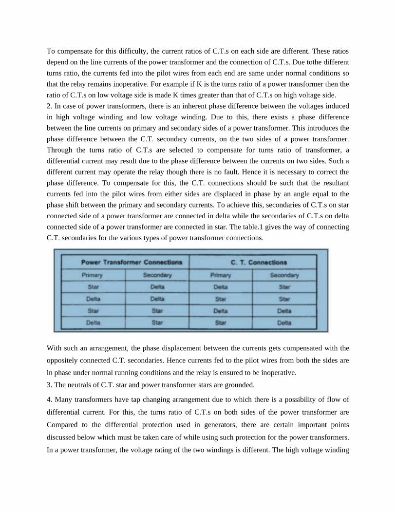
2. In case of power transformers, there is an inherent phase difference between the voltages induced
in high voltage winding and low voltage winding. Due to this, there exists a phase difference
between the line currents on primary and secondary sides of a power transformer. This introduces the
phase difference between the C.T. secondary currents, on the two sides of a power transformer.
Through the turns ratio of C.T.s are selected to compensate for turns ratio of transformer, a
differential current may result due to the phase difference between the currents on two sides. Such a
different current may operate the relay though there is no fault. Hence it is necessary to correct the
phase difference. To compensate for this, the C.T. connections should be such that the resultant
currents fed into the pilot wires from either sides are displaced in phase by an angle equal to the
phase shift between the primary and secondary currents. To achieve this, secondaries of C.T.s on star
connected side of a power transformer are connected in delta while the secondaries of C.T.s on delta
connected side of a power transformer are connected in star. The table.1 gives the way of connecting
C.T. secondaries for the various types of power transformer connections.
With such an arrangement, the phase displacement between the currents gets compensated with the
oppositely connected C.T. secondaries. Hence currents fed to the pilot wires from both the sides are
in phase under normal running conditions and the relay is ensured to be inoperative.
3. The neutrals of C.T. star and power transformer stars are grounded.
4. Many transformers have tap changing arrangement due to which there is a possibility of flow of
differential current. For this, the turns ratio of C.T.s on both sides of the power transformer are
Compared to the differential protection used in generators, there are certain important points
discussed below which must be taken care of while using such protection for the power transformers.
In a power transformer, the voltage rating of the two windings is different. The high voltage winding

is low current winding while low voltage winding is high current winding. Thus there always exists
difference in current on the primary and secondary sides of the power transformer. Hence if C.T.s of
same ratio are used on two sides, then relay may get operated through there is no fault existing.
The star point of the power transformer primary as well as the star connected C.T.
secondaries must be grounded. The restraining coils are connected across the C.T. secondary
windings while the operating coils are connected between the tapping points on the restraining coils
and the star point of C.T. secondaries.
With the proper selection of turns ratio of C.T.s the coils are under balanced condition during normal
operating conditions. The C.T. secondaries carry equal currents which are in phase under normal
conditions. So no current flows through the relay and the relay is inoperative. It is important to note
that this scheme gives protection against short circuit faults between the turns i.e. interturn faults
also. This is because when there is an interturn fault, the turns ratio of power transformer gets
affected. Due to this the currents on both sides of the power transformer become unbalanced. This
causes an enough differential current which floes through the relay and the relay operates.

Buchholz Relay:
All faults below the oil in transformer result in the localized heating & breakdown of the oil,
some degree of arcing will always take place in a winding fault & the resulting decomposition of it
will release gases such as hydrogen, carbon monoxide & hydrocarbons.
When the fault is of a very minor type, such as hot joints gas is released slowly, but a major fault
involving severe arcing causes rapid release of large volumes of gas as well as oil vapour.
Such incipient faults of smaller or larger magnitudes can be detected by a gas actuated relay
known as Bucholtz Relay.
The Bucholtz Relay is contained in a cast housing which is connected as shown below between
the conservator tank and main tank of the transformer.
Under normal conditions, the Buchholz relay is full of oil. It consists of a cast housing containing
a hinged hollow float. A mercury switch is attached to a float. The float being rotated in the upper
part of the housing. Another hinged flap valve is located in the lower part which is directly in the
path of the oil between tank and the conservator. Another mercury switch is attached to a flap valve.
The float closes the alarm circuit while the lower flap valve closes the trip circuit in case of internal
faults.
Operation:
There are many types of internal faults such as insulation fault, core heating, bad switch
contacts, faulty joints etc. which can occur. When the fault occurs the decomposition of oil in the
main tank starts due to which the gases are generated. As mentioned earlier, major component of
such gases is hydrogen. The hydrogen tries to rise up towards conservator but in its path it gets
accumulated in the upper part of the Buchholz relay. Through passage of the gas is prevented by the
flap valve.

When gas gets accumulated in the upper part of housing, the oil level inside the housing falls.
Due to which the hollow float tilts and closes the contacts of the mercury switch attached to it. This
completes the alarm circuit to sound an alarm. Due to this operator knows that there is some incipient
fault in the transformer. The transformer is disconnected and the gas sample is tested. The testing
results give the indication, what type of fault is started developing in the transformer. Hence
transformer can be disconnected before grows into a serious one. The alarm circuit does not
immediately disconnect the transformer but gives only an indication to the operator. This is because
sometimes bubbles in the oil circulating system may operate the alarm circuit even though actually
there is no fault. However if a serious fault such as internal short circuit between phases, earth fault
inside the tank etc. occurs then the considerable amount of gas gets generated. In that case, due to a
fast reduction in the level of oil, the pressure in the tank increases. Due to this the oil rushes towards
the conservator. While doing so it passes through the relay where flap valve is present. The flap valve
gets deflected due to the rushing oil and operates the mercury switch, thereby energizing the trip
circuit which opens the circuit breaker of transformer is totally disconnected from the supply. The
connecting pipebetween the tank and the conservator should be as straight as possible and should
slope upwards conservator at a small angle from the horizontal. This angle should be around 100. For
the economic considerations, Buchholz relays are not provided for the transformer having rating
below 500 KVA.

Advantages:
The various advantages of the Buchholz relay are,
1. Normally a protective relay does not indicate the appearance of the fault. It operates when fault
occurs. But Buchholz relay gives an indication of the fault at very early stage, by anticipating the
fault and operating the alarm circuit. Thus the transformer can be taken out of service before any type
of serious damage occurs.
2. It is the simplest protection in case of transformers.
Limitations:
The various limitations of the Buchholz relay are
1. Can be used only for oil immersed transformers having conservator tanks.
2. Only faults below oil level are detected.
3. Setting of the mercury switches cannot be kept too sensitive otherwise the relay can operate due to
bubbles, vibration, earthquakes mechanical shocks etc.
4. The relay is slow to operate having minimum operating time of 0.1 seconds and average time of
0.2 seconds.
