unit 5 cnc machining 1. define nc? · 2018-12-18 · unit – 5 cnc machining 1. define nc?...
TRANSCRIPT

UNIT – 5
CNC MACHINING 1. Define NC?
Controlling a machine tool by means of a prepared program is
known as numerical control or NC.
2. what are the classifications of NC machines?
1.point to point NC system
2. straight cut NC system
3.Contouring NC system
3. What are G-codes and M-codes? Give examples.
G-codes are preparatory function codes which prepare the machine
are for different modes of movement like positioning, contouring,
thread cutting etc.
Eg. G00 – Point to point positioning
G01 – linear interpolation
M- codes are miscellaneous function codes which denote the
auxillary or switching information such as coolant on/off, spindle
speed etc.
Eg. M00 – Program stop
M01 – Optional stop.

4. What is the role of computer for NC machine tool?
computer numerical control is an NC system that utilizes stored
program to perform basic numerical control functions. mini or micro
computer based controller unit is used.
5. Name the various elements of CNC machines?
1.Tape reader
2.Mini computer
3. servos and interface logic
4. Motion feedback
6. What is the role of computer for NC machine tool?
Computer numerical control is an NC system that utilizes stored program to
perform basic numerical control functions. mini or micro computer based
controller unit is used.
7. What is point –to- point (PTP) system?
It is also called positioning system. The objectives of the machine tool
control are to move the cutting tool to a predefined location. The speed or
path is not important in this system
8. Mention the main difference between CNC and DNC?
CNC system can do operations on only one machine at a time. But direct
numerical control involves that at a time a large central computer to direct the
operations of a number of separate NC machines
9. List the commonly used co – ordinate system of CNC machine tools?
Cantilever construction
Bridge construction
Column construction
Gantry construction
10. What is the difference between incremental and absolute system?
In absolute programming, the distance at my point at any instant will
be measured from the origin ( X=0, Y=0).
Whereas in incremental programming, the instant point will be noted
as (X=0,Y=0). Further measurement will be made from the particular
point only.
11. Write down the types of statements in APT language.?
1. Geometric statements
2. Motion statements
3. postprocessor statement
4. special control or Auxiliary statements 12. Define subroutine?
If the same machining operations, which was carried out already, is
to be performed at many different positions on the work piece, it
can be executed by means of a program called as subroutines
UNIT V
CNC MACHINES
PART - B
1.Explain Numerical Control (NC) Machine Tools?
Numerical Control (NC) refers to the method of controlling the manufacturing
operation by means of directly inserted coded numerical instructions into the
machine tool. It is important to realize that NC is not a machining method, rather, it
is a concept of machine control. Although the most popular applications of NC are in
machining, NC can be applied to many other operations, including welding, sheet
metalworking, riveting, etc.
The major advantages of NC over conventional methods of machine control are as
follows:
Higher precision
Machining of complex three-dimensional shapes
Better quality
Higher productivity
Multi-operational machining
Low operator qualification
Types of NC systems
Machine controls are divided into three groups,
Traditional numerical control (NC);
Computer numerical control (CNC);

Distributed numerical control (DNC).
The original numerical control machines were referred to as NC machine tool. They have
“hardwired” control, whereby control is accomplished through the use of punched paper (or
plastic) tapes or cards. Tapes tend to wear, and become dirty, thus causing misreadings. Many other problems arise from the use of NC tapes, for example the need to manual reload
the NC tapes for each new part and the lack of program editing abilities, which increases the lead time. The end of NC tapes was the result of two competing developments, CNC and DNC.
CNC refers to a system that has a local computer to store all required numerical data. While
CNC was used to enhance tapes for a while, they eventually allowed the use of other storage
media, magnetic tapes and hard disks. The advantages of CNC systems include but are not
limited to the possibility to store and execute a number of large programs (especially if a
three or more dimensional machining of complex shapes is considered), to allow editing of
programs, to execute cycles of machining commands, etc.
2.Explain Electric discharge machining?
Electric discharge machining (EDM), sometimes colloquially also referred to as
spark machining, spark eroding, burning, die sinking, or wire erosion, is a
manufacturing process in which a desired shape is obtained using electrical
discharges (sparks). Material is removed from the workpiece by a series of rapidly
recurring current discharges between two electrodes, separated by a dielectric fluid
and subject to an electric voltage. One of the electrodes is called the tool-electrode, or
simply the "tool" or "electrode," while the other is called the workpiece-electrode, or
"workpiece."
When the distance between the two electrodes is reduced, the intensity of the electric
field in the space between the electrodes becomes greater than the strength of the
dielectric (at least in some point(s)), which breaks, allowing current to flow between
the two electrodes. This phenomenon is the same as the breakdown of a capacitor. As
a result, material is removed from both the electrodes. Once the current flow stops (or
it is stopped – depending on the type of generator), new liquid dielectric is usually
conveyed into the inter-electrode volume enabling the solid particles (debris) to be
carried away and the insulating proprieties of the dielectric to be restored. Adding
new liquid dielectric in the inter-electrode volume is commonly referred to as
flushing. Also, after a current flow, a difference of potential between the two
electrodes is restored to what it was before the breakdown, so that a new liquid
dielectric breakdown can occur.
Wire EDM
Also known as wire cutting EDM, wire burning EDM, or traveling wire EDM, this process
uses spark erosion to machine or remove material with a traveling wire electrode from any electrically conductive material. The wire electrode usually consists of brass or zinc-coated
brass material.
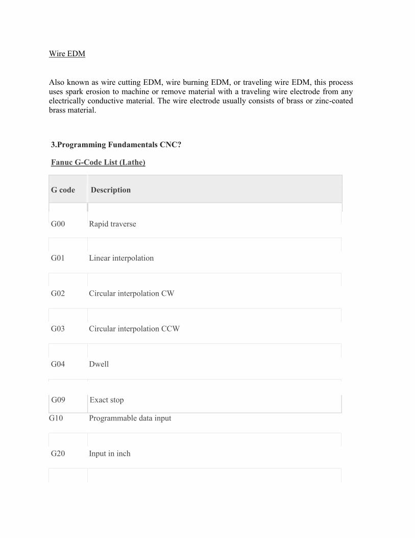
3.Programming Fundamentals CNC?
Fanuc G-Code List (Lathe)
G code
Description
G00 Rapid traverse
G01 Linear interpolation
G02 Circular interpolation CW
G03 Circular interpolation CCW
G04 Dwell
G09 Exact stop
G10 Programmable data input
G20 Input in inch

G21 Input in mm
G22 Stored stroke check function on
G23 Stored stroke check function off
G27 Reference position return check
G28 Return to reference position
G32 Thread cutting
G40 Tool nose radius compensation cancel
G41 Tool nose radius compensation left
G42 Tool nose radius compensation right
G70 Finish machining cycle
G71 Turning cycle
G72 Facing cycle
G73 Pattern repeating cycle

G74 Peck drilling cycle
G75 Grooving cycle
G76 Threading cycle
G92 Coordinate system setting or max. spindle speed setting
G94 Feed Per Minute
G95 Feed Per Revolution
G96 Constant surface speed control
G97 Constant surface speed control cancel
4.Explain Fanuc G-Code List (Mill)?
G00 Rapid traverse
G01 Linear interpolation
G02 Circular interpolation CW
G03 Circular interpolation CCW
G04 Dwell
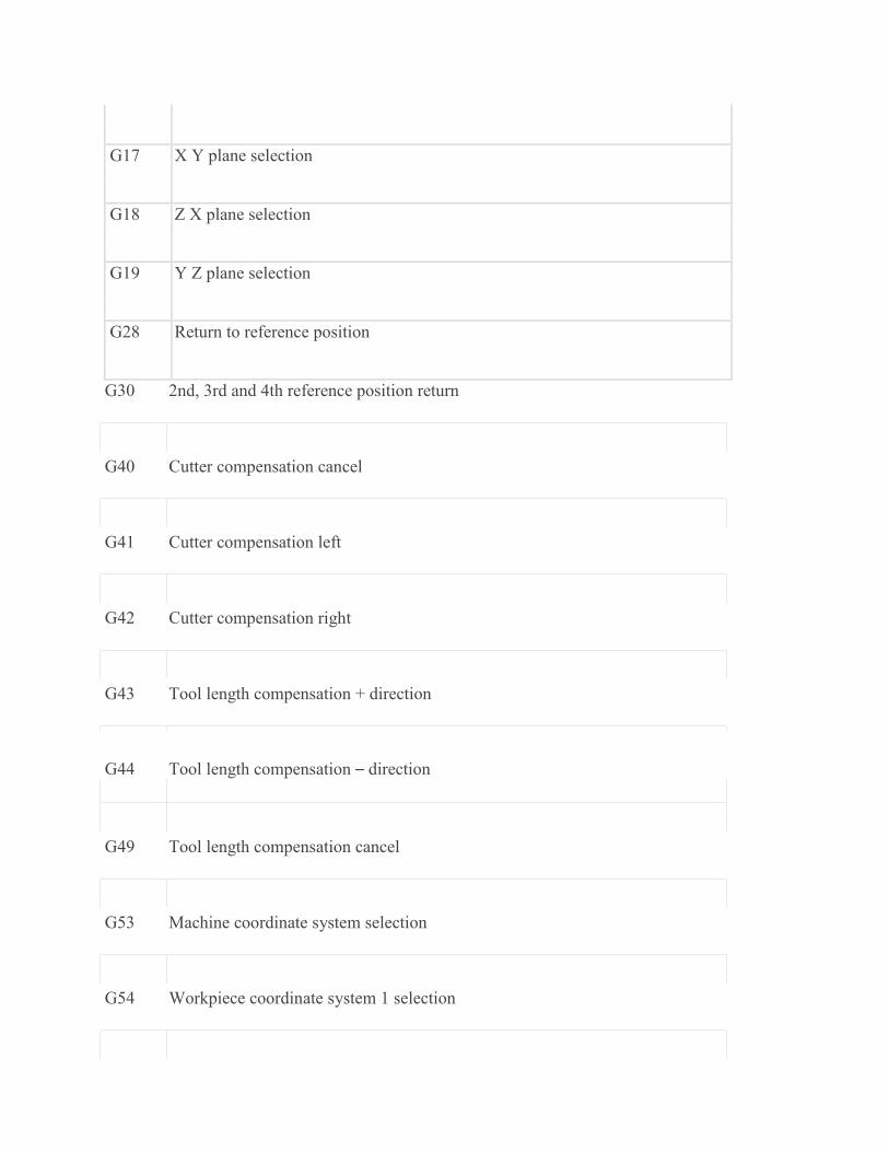
G17 X Y plane selection
G18 Z X plane selection
G19 Y Z plane selection
G28 Return to reference position
G30 2nd, 3rd and 4th reference position return
G40 Cutter compensation cancel
G41 Cutter compensation left
G42 Cutter compensation right
G43 Tool length compensation + direction
G44 Tool length compensation – direction
G49 Tool length compensation cancel
G53 Machine coordinate system selection
G54 Workpiece coordinate system 1 selection

G55 Workpiece coordinate system 2 selection
G56 Workpiece coordinate system 3 selection
G57 Workpiece coordinate system 4 selection
G58 Workpiece coordinate system 5 selection
G59 Workpiece coordinate system 6 selection
G68 Coordinate rotation
G69 Coordinate rotation cancel
G73 Peck drilling cycle
G74 Left-spiral cutting circle
G76 Fine boring cycle
G80 Canned cycle cancel
G81 Drilling cycle, spot boring cycle
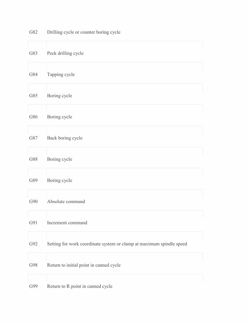
G82 Drilling cycle or counter boring cycle
G83 Peck drilling cycle
G84 Tapping cycle
G85 Boring cycle
G86 Boring cycle
G87 Back boring cycle
G88 Boring cycle
G89 Boring cycle
G90 Absolute command
G91 Increment command
G92 Setting for work coordinate system or clamp at maximum spindle speed
G98 Return to initial point in canned cycle
G99 Return to R point in canned cycle

5.Explain Manual Part Programming?
Lathe
G02 G03 G Code Circular Interpolation
G02 G Code Clock wise Circular Interpolation.
G03 G Code Counter Clock wise Circular Interpolation.
There are multiple articles/cnc program examples about G code circular interpolation, here
is the list of few articles so that cnc machinists can easily navigate through different cnc programming articles.
G02 G03 G Code Example CNC Programs (G code Arc Examples)
o CNC Circular Interpolation Tutorial G02 G03 o Fanuc CNC Lathe Programming Example
o CNC Programming Example G Code G02 Circular Interpolation Clockwise o Fanuc G20 Measuring in Inches with CNC Program Example
o CNC Arc Programming Exercise
o CNC Programming for Beginners a CNC Programming Example o CNC Lathe Programming Example
Here is a new CNC programming examples which shows the use of G02 G03 G code circular interpolation.
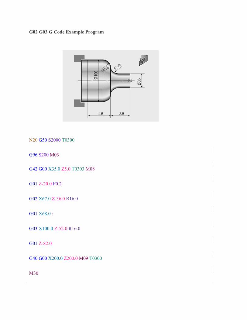
G02 G03 G Code Example Program
N20 G50 S2000 T0300
G96 S200 M03
G42 G00 X35.0 Z5.0 T0303 M08
G01 Z-20.0 F0.2
G02 X67.0 Z-36.0 R16.0
G01 X68.0 :
G03 X100.0 Z-52.0 R16.0
G01 Z-82.0
G40 G00 X200.0 Z200.0 M09 T0300
M30

G Code G02 G03 I & K Example Program
G02 G03 G Code Circular Interpolation can be programmed in two ways,
G02 X... Z... R...
G02 X... Z... I... K...
The below is the same cnc program but this version uses I & K with G02 G03 G code.
N20 G50 S2000 T0300
G96 S200 M03
G42 G00 X35.0 Z5.0 T0303 M08
G01 Z-20.0 F0.2
G02 X67.0 Z-36.0 I16.0 K0
G01 X68.0 :
G03 X100.0 Z-52.0 I0 K-16.0
G01 Z-82.0
G40 G00 X200.0 Z200.0 M09 T0300
M30

6.Explain Micromachining?
Superfinishing, a metalworking process for producing very fine surface finishes
Various micro electro mechanical systems
Bulk micromachining
Surface micromachining
High-aspect-ratio microstructure technologies
Bulk micromachining is a process used to produce micro machinery or micro electro mechanical systems (MEMS).
Unlike surface micromachining, which uses a succession of thin film deposition and
selective etching, bulk micromachining defines structures by selectively etching inside a substrate. Whereas surface micromachining creates structures on top of a
substrate, bulk micromachining produces structures inside a substrate.
Usually, silicon wafers are used as substrates for bulk micromachining, as they can be anisotropically wet etched, forming highly regular structures. Wet etching typically
uses alkaline liquid solvents, such as potassium hydroxide (KOH) or
tetramethylammonium hydroxide (TMAH) to dissolve silicon which has been left
exposed by the photolithography masking step. These alkali solvents dissolve the
silicon in a highly anisotropic way, with some crystallographic orientations
dissolving up to 1000 times faster than others. Such an approach is often used with
very specific crystallographic orientations in the raw silicon to produce V-shaped
grooves. The surface of these grooves can be atomically smooth if the etch is carried
out correctly, and the dimensions and angles can be precisely defined.
Bulk micromachining starts with a silicon wafer or other substrates which is
selectively etched, using photolithography to transfer a pattern from a mask to the
surface. Like surface micromachining, bulk micromachining can be performed with
wet or dry etches, although the most common etch in silicon is the anisotropic wet
etch. This etch takes advantage of the fact that silicon has a crystal structure, which
means its atoms are all arranged periodically in lines and planes. Certain planes have
weaker bonds and are more susceptible to etching. The etch results in pits that have
angled walls, with the angle being a function of the crystal orientation of the
substrate. This type of etching is inexpensive and is generally used in early, low-
budget research.

Unlike Bulk micromachining, where a silicon substrate (wafer) is selectively etched
to produce structures, surface micromachining builds microstructures by deposition
and etching of different structural layers on top of the substrate. Generally
polysilicon is commonly used as one of the layers and silicon dioxide is used as a
sacrificial layer which is removed or etched out to create the necessary void in the
thickness direction. Added layers are generally very thin with their size varying from
2-5 Micro metres. The main advantage of this machining process is the possibility of
realizing monolithic microsystems in which the electronic and the mechanical
components(functions) are built in on the same substrate. The surface micromachined
components are smaller compared to their counterparts, the bulk micromachined
ones.
7.Explain Water Machining?
A water jet cutter, also known as a waterjet or waterjet, is an industrial tool capable of
cutting a wide variety of materials using a very high-pressure jet of water, or a mixture of
water and an abrasive substance. The term abrasive jet refers specifically to the use of a
mixture of water and abrasive to cut hard materials such as metal or granite, while the terms
pure waterjet and water-only cutting refer to waterjet cutting without the use of added
abrasives, often used for softer materials such as wood or rubber. Waterjet cutting is often
used during fabrication of machine parts. It is the preferred method when the materials being
cut are sensitive to the high temperatures generated by other methods. Waterjet cutting is
used in various industries, including mining andaerospace, for cutting, shaping, and reaming.