unit 3 spread spectrum comm - 140.113.144.123
TRANSCRIPT

Dept. of Electrical and Computer Eng., NCTU 1
Unit 3 – Spread Spectrum Modulation
Instructor: Sau-Hsuan Wu

Comm. Systems Unit 3 – Spread Spectrum Comm. Sau-Hsuan Wu
What is spread spectrum modulation? A means of transmission in which data sequences occupy a
bandwidth (BW) in excess of the minimum necessary BW
Why do we need spread spectrum modulation? Interference rejection in multiple access channels Secure communications in a hostile environment where a
transmitter may attempt to jam the transmission
Dept. of Electrical and Computer Eng., NCTU 2
Comm. Systems Unit 3 – Spread Spectrum Comm. Sau-Hsuan Wu
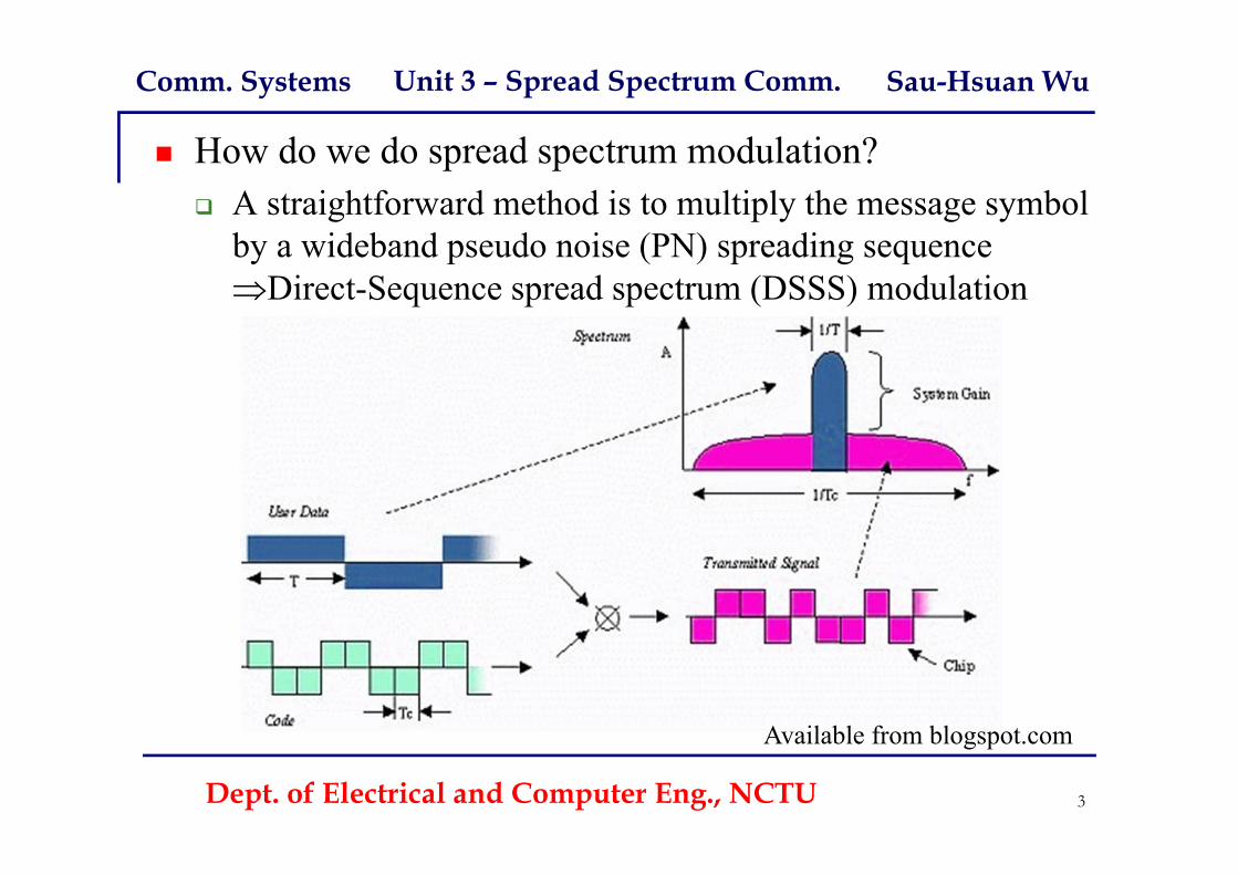
How do we do spread spectrum modulation? A straightforward method is to multiply the message symbol
by a wideband pseudo noise (PN) spreading sequence Direct-Sequence spread spectrum (DSSS) modulation
Dept. of Electrical and Computer Eng., NCTU 3
Available from blogspot.com

Comm. Systems Unit 3 – Spread Spectrum Comm. Sau-Hsuan Wu
Denote the transmit DSSS signal by m(t) = c(t)b(t) c(t) stands for the wideband PN signal b(t) is the narrowband message signal
The received signal is r(t) = m(t) + i(t) = c(t)b(t) + i(t) i(t) is an additive interference
Dept. of Electrical and Computer Eng., NCTU 4

Comm. Systems Unit 3 – Spread Spectrum Comm. Sau-Hsuan Wu
How do we do demodulation for DSSS? The same PN spreading code is used in the receiver to de-
spread the received signal
Dept. of Electrical and Computer Eng., NCTU 5
Available from blogspot.com

Comm. Systems Unit 3 – Spread Spectrum Comm. Sau-Hsuan Wu
Suppose that the receiver operates in perfect synchronism with the transmitter
The multiplier output z(t) = c(t)r(t) = c2(t)b(t) + c(t)i(t)
Since c2(t) = 1, we have z(t) = b(t) + c(t)i(t) The spreading code c(t) will affect the interference i(t) just as
it did to the original signal b(t) Applying z(t) to a low-pass filter with a BW just large
enough to accommodate b(t), most of c(t)i(t) is filtered out The low-pass filtering action is performed by the integrator
Dept. of Electrical and Computer Eng., NCTU 6

Comm. Systems Unit 3 – Spread Spectrum Comm. Sau-Hsuan Wu
DSSS with coherent BPSK
Dept. of Electrical and Computer Eng., NCTU 7

Comm. Systems Unit 3 – Spread Spectrum Comm. Sau-Hsuan Wu
In normal form, spectrum spreading is performed prior to phase modulation
For the purpose of analysis, it is more convenient to exchange the order of PN code generator and BPSK modulator, leading to the following structure
y(t) = x(t) + j(t) u(t) = c(t)y(t) = c2(t)s(t) + c(t)j(t) = s(t) + c(t)j(t)
Dept. of Electrical and Computer Eng., NCTU 8

Comm. Systems Unit 3 – Spread Spectrum Comm. Sau-Hsuan Wu
Signal-Space dimensionality and processing gain Consider the set of orthonormal basis functions:
2cos 2 , 1
0, otherwise2sin 2 , 1
0, otherwise
, 0,1, 2, … 1
where Tc is the chip duration, and N is the number of chips per bit The transmitted DS/BPSK signal x(t) may be expressed as
2cos 2
where {c0, c1, …cN-1} denotes the PN sequence, with ck = 1Dept. of Electrical and Computer Eng., NCTU 9

Comm. Systems Unit 3 – Spread Spectrum Comm. Sau-Hsuan Wu
The transmitted signal x(t) is therefore N-dimensional in that it requires a minimum of N orthonormal basis functions for its representation
For the jamming signal j(t), however, it has no knowledge of the signal phase of x(t) the spreading code of x(t), rather only has the bandwidth of x(t) Accordingly, we may represent the jammer j(t) by a general form
, 0
where , 0, … , 1
, 0, … , 1
Thus, j(t) is 2N-dimensional, thought x(t) is N-dimensional
Dept. of Electrical and Computer Eng., NCTU 10
Comm. Systems Unit 3 – Spread Spectrum Comm. Sau-Hsuan Wu
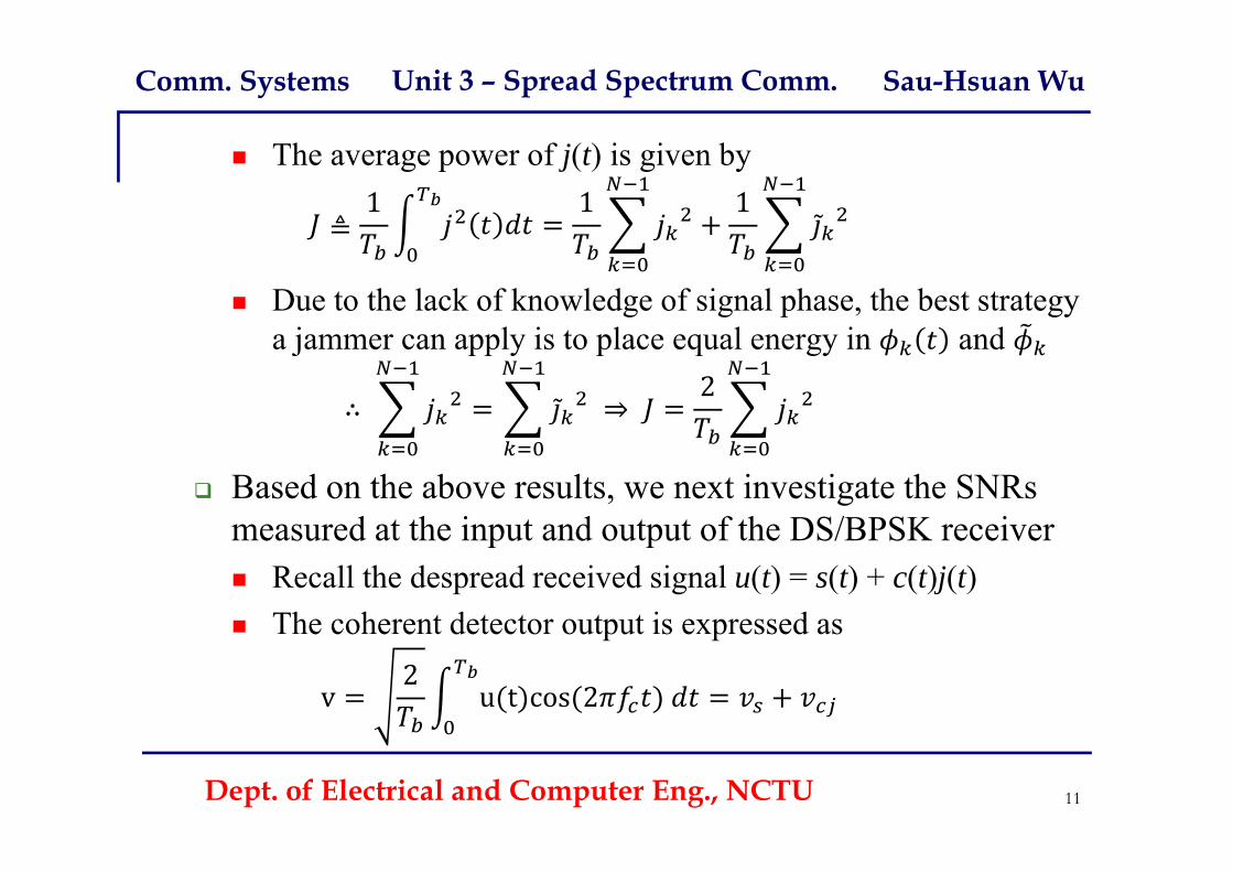
The average power of j(t) is given by
≜1 1 1
Due to the lack of knowledge of signal phase, the best strategy a jammer can apply is to place equal energy in and
∴ ⇒ 2
Based on the above results, we next investigate the SNRs measured at the input and output of the DS/BPSK receiver Recall the despread received signal u(t) = s(t) + c(t)j(t) The coherent detector output is expressed as
v2
u t cos 2
Dept. of Electrical and Computer Eng., NCTU 11

Comm. Systems Unit 3 – Spread Spectrum Comm. Sau-Hsuan Wu
The signal component in the detector output is given by2
s t cos 2 2
cos 2
The plus sign corresponds to symbol 1, and the minus corresponds to symbol 0
Supposing that fc is an integer multiple of 1/Tb
The component from the jamming signal, on the other hand, is given by
2c t t cos 2
t ϕ
Where Tc is the chip duration
Dept. of Electrical and Computer Eng., NCTU 12

Comm. Systems Unit 3 – Spread Spectrum Comm. Sau-Hsuan Wu
Now, approximate the PN sequence {ck} as an i.i.d. binary sequence, and the jammer to be fixed for a long period of time Define R.V. Vcj and Ck with sample values vcj and ck, respectively
For a fixed jammer jk, we may define ∑
Given that P(Ck = 1) = P(Ck = 1) = ½, we haveE[Ck jk | jk] = P(Ck = 1) jk P(Ck = 1) jk = ½ [jk jk] = 0
Consequently, for a fixed jammer: j = [j0 j1 ,…, jN-1], we have
Var Vcj | j ≜
12
Where N = Tb / Tc is referred to as the spreading factor As a result, the output SNR of the detector follows
SNR Var Vcj | j
2
Dept. of Electrical and Computer Eng., NCTU 13

Comm. Systems Unit 3 – Spread Spectrum Comm. Sau-Hsuan Wu
On the other hand, the average signal power at the receiver input is , which gives the input SNR of the receiver as
SNR
Therefore, it follows that
SNR2
SNR
This motivates us to define a processing gain (PG) of Tb /Tcas the gain in SNR obtained by the use of spread spectrum The longer is the PN sequence, (or the smaller the chip time Tc
is), the larger will be the PG We may also express the output SNR in decibel as
10log10(SNRO) = 10log10(SNRI) + 3 + 10log10(PG) dB The 3 dB term results from the use of coherent detection
Dept. of Electrical and Computer Eng., NCTU 14

Comm. Systems Unit 3 – Spread Spectrum Comm. Sau-Hsuan Wu
Probability of error Recall the detector output v = vs + vcj, where Let v be the sample value of a RV V The signal model of the coherent detector of DS/BPSK is
The BER is 0 0issent
Therefore, Pe depends on the PDF of ∑
By the central limit theorem, Vcj is approximately Gaussian with zero mean and Var Vcj
|j /2, i.e. Vcj ~N(0, JTc/2) when N is large Making use of the BER of BPSK, similarly we have
12 erfc ⇒ ≃
12 erfc
Dept. of Electrical and Computer Eng., NCTU 15

Comm. Systems Unit 3 – Spread Spectrum Comm. Sau-Hsuan Wu
Antijam characteristic We may relate the BER of DS/BPSK to that of the typical
BPSK by considering N0/2 = JTc/2 Given that the symbol energy is PTb = Eb, we may also
interpret the typical SNR as
⟹ / Let (Eb/N0)min be the the minimum SNR required to support a
prescribed BER We therefore may define a jamming margin, J/P, which is
related to (Eb/N0)min by the following form
10 log
The higher the PG, the greater the ability to combat jamming
Dept. of Electrical and Computer Eng., NCTU 16

Comm. Systems Unit 3 – Spread Spectrum Comm. Sau-Hsuan Wu
Ex. 1 A spread spectrum system has the following parameters
Tb = 4.095 ms and Tc = 1us The processing gain (PG) = 4095 Assume that we need Pe 10-5
For BPSK, when Eb/N0 = 10, 12 erfc
12 erfc 10 0.387 10 10
10 log
10 log 4095 10 log 1036.1 10 26.1dB
Information bits can be detected reliably even when the noise or interference at receiver input is 409.5 times the received signal power
Dept. of Electrical and Computer Eng., NCTU 17

Comm. Systems Unit 3 – Spread Spectrum Comm. Sau-Hsuan Wu
For DSSS, spreading is achieved instantaneously by using a PN sequence to modulate a PSK/QAM/FSK signal Anti-jam capability is determined by the processing gain The processing gain can be made larger with:
A narrow chip duration or more numbers of chips per bit
What if the spreading gain is still not large enough to overcome the effects of jammer? Force the jammer to cover a wider spectrum by randomly
hopping the carrier from one frequency to the next Frequency-Hop (FH) Spread Spectrum
The spectrum of the transmitted signal is spread sequentially Pseudo-random-ordered sequence of frequency hops
Dept. of Electrical and Computer Eng., NCTU 18

Comm. Systems Unit 3 – Spread Spectrum Comm. Sau-Hsuan Wu
A common modulation format for FH systems is M-ary FSK FH/MFSK Slow-Frequency Hopping: Several symbols are transmitted on
each frequency hop, i.e. symbol rates Rs = n hop rate Rh, nN Fast-Frequency Hopping: Rh = n Rs, i.e, the carrier frequency
will hop several times during the transmission of one symbol
Dept. of Electrical and Computer Eng., NCTU 19
For Fast-FH, we use noncoherent detection
only because frequency synthesizers are unable to maintain phase coherent
over multiple hops
For a k-bit PN code, there are 2k FHs

Comm. Systems Unit 3 – Spread Spectrum Comm. Sau-Hsuan Wu
Ex. 2: Illustration of aslow FH/MFSK system # of bits/sym: K = 2 MFSK tones: M =2K= 4 Len of PN seq. : k = 3 # of FH: 2k = 8 For non-coherent MFSK
B = 2KRs
Wc = 2kB
Dept. of Electrical and Computer Eng., NCTU 20
Dehopped frequencies
B

Comm. Systems Unit 3 – Spread Spectrum Comm. Sau-Hsuan Wu
For FH/MFSK systems, an individual tone of the shortest duration is referred to as a chip (not the DSSS chip interval) The chip rate is defined by Rc = max (Rh, Rs), where Rh is the
hop rate and Rs is the symbol rate For a slow FH/MFSK signal, each symbol is a chip, such
that Rc = Rs = Rb /K Rh, where K = log2 M At each hop, the MFSK tones are still separated in frequency
by an integer multiple of the symbol rate, also the chip rate As such, orthogonality is still maintained in a slow FH/MFSK The jamming signal has an effect on the FH/MFSK, in terms
of SER, equivalent to that of AWGN on an MFSK system We, thus, may use the BER of MFSK for approximate
evaluation of the SER in the FH/MFSK system
Dept. of Electrical and Computer Eng., NCTU 21

Comm. Systems Unit 3 – Spread Spectrum Comm. Sau-Hsuan Wu
Assuming that the jammer spreads its power J over the entire FH spectrum, the jammer’s effect is equivalent to an AWGN with N0 = J/Wc, and Wc is the FH bandwidth
The FH/MFSK system is thus characterized by the symbol energy-to-noise spectral density ratio of
//
The ratio of P/J is the reciprocal of the jamming margin For an MFSK with a frequency spacing , the output BW is ≅ 2
The processing gain (PG) of a FH/MFSK system is defined as Wc /B = 2
Rs
2Rs
2 PG ⇔ 10 log 3 10 log
This PG assumes the jammer spreads its power over the entire FH spectrum However, if a jammer decides to concentrate on just a few of the hopped
frequencies, the PG would be less than 3k decibels.
Dept. of Electrical and Computer Eng., NCTU 22

Comm. Systems Unit 3 – Spread Spectrum Comm. Sau-Hsuan Wu
For a fast FH/MFSK signal, each hop is a chip, such that there are multiple hops per M-ary symbol Noncoherent detection is used for data recovery For each FH/MFSK symbol, two procedures may be
considered for detection A majority vote approach:
Separate decisions are made on the K FH chips received A majority vote is used to make an estimate of the dehopped
MFSK symbol A maximum likelihood approach:
For each FH/MFSK symbol, likelihood functions are computed as functions of the total signals received over K chips
The largest one is selected This is optimal in the sense that it minimizes the average SER
Dept. of Electrical and Computer Eng., NCTU 23

Comm. Systems Unit 3 – Spread Spectrum Comm. Sau-Hsuan Wu
Ex. 2: Illustration of afast FH/MFSK system # of bits/sym: K = 2 MFSK tones: M =2K= 4 Len of PN seq. : k = 3 # of FH: 2k = 8 Rc = Rb = KRs
Min tone spacing isKRs and B = 2KKRs
PG 2
Dept. of Electrical and Computer Eng., NCTU 24
Dehopped frequencies
B

Comm. Systems Unit 3 – Spread Spectrum Comm. Sau-Hsuan Wu
HW5 (due on 6/3) 7.7, 7.10, 7.11, 7.12, and 7.13
Dept. of Electrical and Computer Eng., NCTU 25

Comm. Systems Unit 3 – Spread Spectrum Comm. Sau-Hsuan Wu
Dept. of Electrical and Computer Eng., NCTU 26

Comm. Systems Unit 3 – Spread Spectrum Comm. Sau-Hsuan Wu
Dept. of Electrical and Computer Eng., NCTU 27
Comm. Systems Unit 3 – Spread Spectrum Comm. Sau-Hsuan Wu
Dept. of Electrical and Computer Eng., NCTU 28

Comm. Systems Unit 3 – Spread Spectrum Comm. Sau-Hsuan Wu
Dept. of Electrical and Computer Eng., NCTU 29

Comm. Systems Unit 3 – Spread Spectrum Comm. Sau-Hsuan Wu
Dept. of Electrical and Computer Eng., NCTU 30

Comm. Systems Unit 3 – Spread Spectrum Comm. Sau-Hsuan Wu
Dept. of Electrical and Computer Eng., NCTU 31