unit 2 power frequency disturbances
TRANSCRIPT

Unit 2Power Frequency Disturbances
Reference Book 1: C. Sankaran: Power Quality, CRC PRESS
Reference Book 2: Roger C. Dugan: Electrical Power Systems Quality, Second Edition, Mac Graw Hill Publication.

• The term power frequency disturbance describes events that are slower and longer lasting compared to electrical transients.
• Power frequency disturbances can last anywhere from one complete cycle to several seconds or even minutes.
• While the disturbance can be nothing more than an inconveniencemanifesting itself as a flickering of lights or bumpy ride in an elevator,in other instances the effects can be harmful to electrical equipment.

• The deleterious effects of power frequency disturbances arepredominantly felt in the long run, and such disturbances do not resultin immediate failure of electrical devices.
• The effects of power frequency disturbances vary from one piece ofequipment to another and with the age of the equipment. Equipmentthat is old and has been subjected to harmful disturbances over aprolonged period is more susceptible to failure than new equipment.
• Power frequency disturbances are slower and longer lasting events,they are easily measured using instrumentation that is simple inconstruction.

Interruptions (momentary and sustained)
• A type of short-duration variation. The complete loss of voltage (<0.1 pu) on one or more phase conductors for a time period between 30 cycles and 3s is called momentary interruption.
• When the supply voltage has been zero for a period of time in excess of 1 min, the long-duration voltage variation is considered a sustained interruption.
• Voltage interruptions longer than 1 min are often permanent and require human intervention to repair the system for restoration

• Interruptions can be the result of power system faults, equipment failures, and control malfunctions.
• The interruptions are measured by their duration since the voltage magnitude is always less than 10 percent of nominal.
• Instantaneous reclosing generally will limit the interruption caused by a non-permanent fault to less than 30 cycles.
• Some interruptions may be preceded by a voltage sag when these interruptions are due to faults on the source system.
• The voltage sag occurs between the time a fault initiates and the protective device operates

Common Power Frequency Disturbances
Voltage sags: • Voltage sag is an event that can last from half of a cycle to several
seconds. Voltage sags typically are due to starting on large loads, suchas an electric motor or an arc furnace.
• Voltage sags are usually associated with system faults but can also be caused by energization of heavy loads or starting of large motors.
• Induction motors draw starting currents ranging between 600 and800% of their nominal full load currents.

Voltage sag caused by an SLG fault. (a) RMS waveform for voltage sag event. (b) Voltage sag waveform.

Temporary voltage sag caused by motor starting.

• Figure 2.2 contains the waveform of the starting current of a 50-hpinduction motor with a rated full-load current of 60 A at 460 VAC.During the first half of the cycle, the asymmetrical current attains apeak value of 860 A. When the circuit feeding the motor has highimpedance, appreciable voltage sag can be produced.

• The transformer has a leakage reactance of 5.0%, the voltage sag due to starting this motor is calculated as follows:
• Full load current of the 100-kVA transformer at 480 V = 120 A. Voltage drop due to the starting inrush = 5.0 ×860 ÷(120 X √2) = 25.3%.
• If the reactance of the power lines and the utility transformer feeding this transformer were included in the calculations, the voltage sag would be worse than the value indicated. It is not difficult to see that any device that is sensitive to a voltage sag of 25% would be affected by the motor starting event.

• Arc furnaces are another example of loads that can produce largevoltage sags in electrical power systems. Arc furnaces operate byimposing a short circuit in a batch of metal and then drawing an arc,which produces temperatures in excess of 10,000˚C, which melt themetal batch.
• Arc furnaces employ large inductors to stabilize the current due tothe arc. Tens of thousands of amperes are drawn during the initial fewseconds of the process.
• Figure 2.3 depicts typical current drawn by an arc furnace. Once thearc becomes stable, the current draw becomes more uniform. Due tothe nature of the current drawn by the arc furnace, which isextremely nonlinear, large harmonic currents are also produced.Severe voltage sags are common in power lines that supply large arcfurnaces, which are typically rated in the 30- to 50-MVA range andhigher.

An Electric Arc Furnace (EAF) is
a furnace that heats charged material by
means of an electric arc.
Industrial arc furnaces range in size from
small units of approximately one ton capacity
(used in foundries for producing cast iron
products) up to about 400 ton units used for
secondary steelmaking. Arc furnaces used in
research laboratories and by dentists may have
a capacity of only a few dozen grams.
Industrial electric arc furnace temperatures
can be up to 1,800 °C (3,272 °F), while
laboratory units can exceed 3,000 °C
(5,432 °F).
Arc furnaces differ from induction furnaces in
that the charge material is directly exposed to
an electric arc and the current in the furnace
terminals passes through the charged material.


• Arc furnaces are operated in conjunction with large capacitor banksand harmonic filters to improve the power factor and also to filter theharmonic frequency currents so they do not unduly affect other powerusers sharing the same power lines.
• Arc furnaces are supplied from dedicated utility power lines tominimize their impact on other power users.
• The presence of large capacitance in an electrical system can result involtage rise due to the leading reactive power demands of thecapacitors, unless they are adequately cancelled by the laggingreactive power required by the loads.
• Capacitor banks, whether for power factor correction or harmoniccurrent filtration, are switched on when the furnace is brought on lineand switched off when the arc furnace is off line

Sag Due to Utility Faults
• Utility faults are also responsible for voltage sags. Approximately 70% of the utility-related faults occur in overhead power lines.
• Some common causes of utility faults are lightning strikes, contactwith trees or birds and animals, and failure of insulators.
• The utility attempts to clear the fault by opening and closing thefaulted circuit using reclosers, which can require from 40 to 60 cycles.
• The power line experiences voltage sags or total loss of power for theshort duration it takes to clear the fault.
• If the fault persists, the power outage continues until the problem iscorrected

Example of fault locations that caused misoperation of sensitiveproduction equipment at an industrial facility (the example systemhad multiple overhead distribution feeders and an extensive overheadtransmission system

Fig. shows voltage sag due to a
utility fault near a refinery. This
fault was attributed to stormy
weather conditions just prior to
the event. The sag lasted for
approximately 21 cycles before
the conditions returned to normal.
The duration of the sag was
sufficient to affect the operation of
very critical process controllers in
the refinery, which interrupted
refinery production

Fig. indicates voltage sag caused by utility
switching operations near an aluminium smelter.
Even though the sag lasted for only five cycles in
this particular case, its magnitude was sufficient
to cause several motor controllers to drop offline.
Typically, electromagnetic controllers could ride
through such events due to energy stored in their
magnetic fields; however, the motor controllers
in this facility contained electronic voltage-
sensing circuits more sensitive to the voltage
sags. In such cases, either the sensitive circuit
should be adjusted to decrease its sensitivity or
voltage-support devices such as capacitors or
batteries should be provided

• Voltage sags and swells are also generated when loads are transferred from one power source to another.
• One example is transfer of load from the utility source to the standby generator source during loss of utility power.
• Most facilities contain emergency generators to maintain power tocritical loads in case of an emergency. Sudden application andrejection of loads to a generator could create significant voltage sagsor swells.
• Sudden application and rejection of loads to a generator could createsignificant voltage sags or swells.
• If critical loads are not able to withstand the imposed voltageconditions, problems are imminent.

• Such determinations should be made at the time when thegenerators are commissioned into service. The response of thegenerator or the sensitivity of the loads, or a combination of each,should be adjusted to obtain optimum performance.
• During power transfer from the utility to the generator, frequencydeviations occur along with voltage changes. The generator frequencycan fluctuate as much as ±5 Hz for a brief duration during this time.
• It is important to ensure that sensitive loads can perform satisfactorilywithin this frequency tolerance for the duration of the disturbance.

Voltage sag due to generator step load application. The nominal 480-V generator
bus experienced a sag to 389 V that lasted for approximately 1 sec.

Voltage swell due to step load rejection. The nominal 480-V generator bus
experienced a rise to 541 V that lasted for approximately 18 cycles.

Equipment sensitivity to voltage sags• It is often difficult to identify which characteristics of a given voltage
sag are most likely to cause equipment to misoperate.
• The most commonly used characteristics are the duration and magnitude of the sag.
• Other less commonly used characteristics include phase shift and unbalance, missing voltage, three-phase voltage unbalance during the sag event, and the point-in-the-wave at which the sag initiates and terminates.
• Generally, equipment sensitivity to voltage sags can be divided into three categories:

• Equipment sensitive to only the magnitude of a voltage sag: Thisgroup includes devices such as undervoltage relays, process controls,motor drive controls, and many types of automated machines (e.g.,semiconductor manufacturing equipment). The duration of thedisturbance is usually of secondary importance for these devices.
• Equipment sensitive to both the magnitude and duration of a voltage sag: This group includes virtually all equipment that uses electronic power supplies.

• Equipment sensitive to characteristics other than magnitude and duration: Some devices are affected by other sag characteristics such as the phase unbalance during the sag event, the point-in-the wave at which the sag is initiated, or any transient oscillations occurring during the disturbance.
• These characteristics are more subtle than magnitude and duration, and their impacts are much more difficult to generalize.

Classification of Sags.
• Voltage sags can be classified as balanced and unbalanced depending on the type of faults.
• In general, voltage sags can be classified into seven groups.
• The type of the transformer determines the propagation characteristic of the voltage sag through the different voltage levels.
• Voltage sags can be classified as balanced and unbalanced depending on the type of faults.

• A balanced three-phase voltage sag will result in a Type A sag. Sincethe voltage sag is balanced, the zero-sequence is zero, and atransformer will not affect the appearance of the voltage sag. Thisholds both for the phase-to-ground voltage and phase-to-phase-voltage.
• A phase-to-ground fault will result in a Type B sag.
• If there is a transformer that removes the zero-sequence betweenthe fault location and the load, the voltage sag will be of Type D sag.

• A phase-to-phase-fault results in a Type C sag.
• The voltage sags of Types E, F and G are due to a two-phase-to-ground fault.

FLICKER
• Flicker (or light flicker, as it is sometimes called) is a low-frequencyphenomenon in which the magnitude of the voltage or frequencychanges at such a rate as to be perceptible to the human eye.
• Flicker is also a subjective term. Depending on the sensitivity of theobserver, light flicker may or may not be perceived.
• For small voltage changes that occur infrequently, flicker is not aserious concern but certainly can be a source of major annoyance.
• Typically, flicker is caused when a load that requires large currentsduring start-up is initially energized

• If the starts are frequent or if the current requirement of the loadfluctuates rapidly during each cycle of operation, then flicker effectscan be quite pronounced.
• Examples of loads that could cause light flicker are elevators, arcfurnaces, and arc welders.
• Flicker is expressed as:

• Where Vmax and Vmin represent the change in voltage over the nominal voltage Vnom.
• . For example, if the voltage in a circuit rated at 120 V nominal changed from 122 to 115 V, the flicker is given by:
fv = 100× (122 – 115)/120 = 5.83%
• In the early stages of development of AC power, light flicker was aserious problem. Power generation and distribution systems were notstiff enough to absorb large fluctuating currents.
• The flicker problems were not, for the most part, eliminated untillarge generating stations came into service.

• Light flicker due to arc furnaces requires extra mention. Arc furnaces,commonly found in many industrial towns, typically use scrap metalas the starting point. An arc is struck in the metal by applying voltageto the batch from a specially constructed furnace transformer.
• Fig. shows the voltage at a lighting panel supplying a multiunitresidence. The graph shows the voltage change when one of theelevators for the building is operated, during which the voltage at thepanel changes at the rate of 3 to 4 V. The light flicker in the buildingwas quite evident. The problem in this particular building was due toone switchboard feeding both the lighting panel and the elevators.Under these conditions, unless the source supplying the load is large,interaction between the elevator and the lighting is likely to occur.

Voltage changes during elevator operation in a residential multiunit complex.
The rate of voltage change causes perceptible light flicker.

• Arc furnaces impose large electrical power requirements on theelectrical system. The current drawn from the source tends to behighly cyclic as arcs are repeatedly struck and stabilized in differentparts of the batch.
• The voltage at the supply lines to an arc furnace might appear asshown in Fig. The envelope of the change in voltage represents theflicker content of the voltage. The rate at which the voltage changes isthe flicker frequency.
• It has been found that a flicker frequency of 8 to 10 Hz with a voltagevariation of 0.3 to 0.4% is usually the threshold of perception thatleads to annoyance.

Typical arc furnace supply voltage indicating voltage fluctuation at the flicker
frequency.

• Arc furnaces are normally operated with capacitor banks or capacitorbank/filter circuits, which can amplify some of the characteristicfrequency harmonic currents generated by the furnace, leading tosevere light flicker.
• For arc furnace applications, careful planning is essential in theconfiguration and placement of the furnace and the filters tominimize flicker. Very often, arc furnaces are supplied by dedicatedutility power lines that are not shared by other users. This followsfrom the principle that as the voltage source becomes larger (lowersource impedance), the tendency to produce voltage flicker due tothe operation of arc furnaces is lessened.

NOISE
• Low-frequency noise superimposed on the fundamental power frequency is a power quality concern.
• Low-frequency noise is a signal with a frequency that is a multiple of the fundamental power frequency.
• When the capacitor banks are online, no significant noise is noticed inthe power lines. When the capacitor banks are turned off, noise canbe found on the voltage waveform (as shown) because the capacitorbanks absorb the higher order harmonic frequency currents producedby the rectifiers feeding the pot lines.

Low-frequency noise superimposed on the 480-V bus after switching off the
capacitor bank.

• Adjustable speed drives (ASDs) produce noise signals that are very often troublesome. The noise frequency generated by the ASDs is typically higher than the harmonic frequencies of the fundamental voltage. Because of this, the noise could find its way into sensitive data and signal circuits unless such circuits are sufficiently isolated from the ASD power lines

CURES FOR LOW-FREQUENCY DISTURBANCES
Isolation Transformers:
1. Isolation transformers, as their name indicates, have primary and secondary windings, which are separated by an insulating or isolating medium.
2. Isolation transformers do not help in curing voltage sags or swells; they merely transform the voltage from a primary level to a secondary level to enable power transfer from one winding to the other

• If the problem is due to common mode noise, isolation transformershelp to minimize noise coupling, and shielded isolation transformerscan help to a greater degree.
• Common mode noise is equally present in the line and the neutralcircuits with respect to ground. Common mode noise may beconverted to transverse mode noise (noise between the line and theneutral) in electrical circuits, which is troublesome for sensitive dataand signal circuits attenuation.

• Shielded isolation transformers can limit the amount of commonmode noise converted to transverse mode noise. The effectivenesswith which a transformer limits common mode noise is calledattenuation (A) and is expressed in decibels (dB).
where V1 is the common mode noise voltage at the transformer primary and V2 is the differential mode noise at the transformer secondary.

Fig. shows how common modenoise attenuation is obtained bythe use of a shielded isolationtransformer. The presence of ashield between the primary andsecondary windings reduces theinterwinding capacitance andthereby reduces noise couplingbetween the two windings.

VOLTAGE REGULATORS• Voltage regulators are devices that can maintain a constant voltage
(within tolerance) for voltage changes of predetermined limits aboveand below the nominal value.
• A switching voltage regulator maintains constant output voltage byswitching the taps of an autotransformer in response to changes inthe system voltage.
• The electronic switch responds to a signal from the voltage-sensingcircuitry and switches to the tap connection necessary to maintainthe output voltage constant.
• The switching is typically accomplished within half of a cycle, which iswithin the ride-through capability of most sensitive devices.

Tap-changer voltage regulator

• Ferro-resonant voltage regulators are static devices that have no moving components.
• They operate on the principle that, in a transformer, when thesecondary magnetic circuit is operating in the saturation region thesecondary winding is decoupled from the primary and therefore isnot sensitive to voltage changes in the primary.
• The secondary winding has a capacitor connected across its terminalsthat forms a parallel resonant circuit with the inductance of thesecondary winding.

• Large magnetic fields are created in the magnetic core surrounding the secondary windings, thereby decoupling the secondary winding from the primary.
• Typically ferro-resonant transformer regulators can maintain secondary voltage to within ±0.5% for changes in the primary voltages of ±20%.
• Ferro-resonance transformers are sensitive to loads above their rated current. In extreme cases of overload, secondary windings can become detuned, at which point the output of the transformer becomes very low
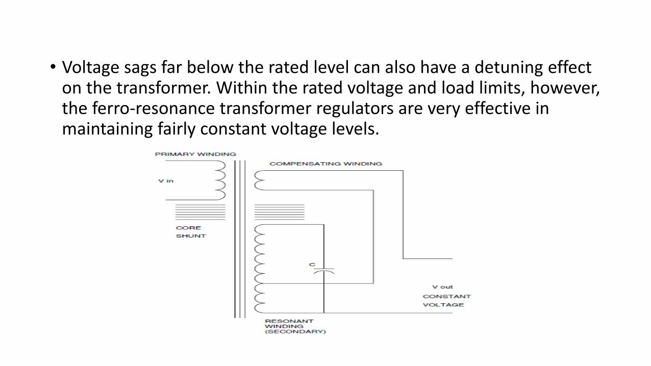
• Voltage sags far below the rated level can also have a detuning effect on the transformer. Within the rated voltage and load limits, however, the ferro-resonance transformer regulators are very effective in maintaining fairly constant voltage levels.

Uninterruptible Power Sources
• Static uninterruptible power sources (UPSs) have no rotating parts, such as motors or generators.
• These are devices that maintain power to the loads during loss ofnormal power for a duration that is a function of the individual UPSsystem.
• All UPS units have an input rectifier to convert the AC voltage into DCvoltage, a battery system to provide power to loads during loss ofnormal power, and an inverter which converts the DC voltage of thebattery to an AC voltage suitable for the load being supplied.

• Static UPS systems may be broadly classified into offline and online units.
• In the offline units, the loads are normally supplied from the primary electrical source directly. The primary electrical source may be utility power or an in-house generator. If the primary power source fails or falls outside preset parameters, the power to the loads is switched to the batteries and the inverter.
• The switching is accomplished within half of a cycle in most UPS units, thereby allowing critical loads to continue to receive power

Offline UPS

• During power transfer from the normal power to the batteries, the loads might be subjected to transients.
• Once the loads are transferred to the batteries, the length of time for which the loads would continue to receive power depends on the capacity of the batteries and the amount of load.
• UPS units usually can supply power for 15 to 30 min, at which timethe batteries become depleted to a level insufficient to supply theloads, and the UPS unit shuts down. Some offline UPS systemmanufacturers provide optional battery packs to enhance the time ofoperation of the units after loss of normal power.
Online UPS
• In online UPS units, normal power is rectified into DC power and inturn inverted to AC power to supply the loads. The loads arecontinuously supplied from the DC bus even during times when thenormal power is available.
• A battery system is also connected to the DC bus of the UPS unit andkept charged from the normal source. When normal power fails, theDC bus is supplied from the battery system. No actual power transferoccurs during this time, as the batteries are already connected to theDC bus.

• Online units can be equipped with options such as manual and static bypass switches to circumvent the UPS and supply power to the loads directly from the normal source or an alternate source such as a standby generator.
• Two important advantages of online UPS units are because: (1) poweris normally supplied from the DC bus, the UPS unit in effect isolatesthe loads from the source which keeps power system disturbancesand transients from interacting with the loads, (2) since power to theloads is not switched during loss of normal power, no switchingtransients are produced. As might be expected, online UPS systemscost considerably more than offline units.

Online UPS

• The output voltage of static UPS units tends to contain waveformdistortions higher than those for normal power derived from the utility or agenerator. This is due to the presence of the inverter in the output sectionof the UPS system. For some lower priced UPS units, the distortion can besubstantial, with the waveform resembling a square wave.
• More expensive units use higher order inverter sections to improve the waveform of the output voltage.
• It is important to take into consideration the level of susceptibility of theloads to waveform distortion. Problems attributed to excessive voltagedistortion have been noticed in some applications involving medicalelectronics and voice communication.

Output voltage waveform from an offline uninterruptible power source (UPS)system

Voltage waveform from an online uninterruptible power source (UPS) system. The waveform, even though less than ideal, contains considerably lower distortion than the waveform of the offline unit

Rotary UPS (RUPS)
• Rotary UPS (RUPS) units utilize rotating members to provideuninterrupted power to loads, as shown in Fig. In this configuration,an AC induction motor drives an AC generator, which supplies powerto critical loads.
• The motor operates from normal utility power. A diesel engine orother type of prime mover is coupled to the same shaft as the motorand the generator.
• During normal operation, the diesel engine is decoupled from thecommon shaft by an electric clutch. If the utility power fails, theprime mover shaft is coupled to the generator shaft and thegenerator get sits mechanical power from the prime mover.

Rotary uninterruptible power source (RUPS) system using a diesel engine, AC motor, and AC generator to supply uninterrupted power to critical loads
Transient Overvoltages• A transient is defined as a sub cycle disturbance in the AC waveform that is
discernible as a sharp discontinuity of the waveform. • The definition states that transients are sub cycle events, lasting less than
one cycle of the AC waveform.• Inclusion of the term sub cycle is for the sake of definition only. Routinely
we see transients that span several cycles• Many different terms are associated with transients, such as spikes, bumps,
power pulses, impulses, and surges.• While some of these terms may indeed describe a particular transient,
such terms are not recommended due to their ambiguity.• Large electromagnetic devices such as transformers and motors are
practically impervious to the effects of transients.• Problems arise because of the sensitivity of the microelectronic devices
and circuits that make up the control elements of the power system

TYPES AND CAUSES OF TRANSIENTS
An electrical transient is a cause-and-effect phenomenon. For transients to occur, there must be a cause
• Atmospheric phenomena (lightning, solar flares, geomagnetic disturbances)
• Switching loads on or off
• Interruption of fault currents
• Switching of power lines
• Switching of capacitor banks

Capacitor switching
• One drawback to the use of capacitors is that they yield oscillatorytransients when switched. Some capacitors are energized all thetime(a fixed bank), while others are switched according to load levels.
One-line diagram of a capacitor-switching operation

Typical utility capacitor-switching transient reaching 134 percent voltage, observed upline from the capacitor.
The overshoot will generate a transientbetween 1.0 and 2.0 pu depending on systemdamping. In this case the transient observed atthe monitoring location is about 1.34 pu.Utility capacitor-switching transients arecommonly in the 1.3- to 1.4-pu range but havealso been observed near the theoreticalmaximum.

Magnification of capacitor-switchingtransients• A potential side effect of adding power factor correction capacitors at the
customer location is that they may increase the impact of utility capacitor-switching transients on end-use equipment.
• The transient is generally no higher than 2.0 pu on the primary distribution system.
• Load-side capacitors can magnify this transient overvoltage at the end-user bus for certain low-voltage capacitor and step-down transformer sizes.
• Transient overvoltages on the end-user side may reach as high as 3.0 to 4.0 pu on the low-voltage bus under these conditions, with potentially damaging consequences for all types of customer equipment

Voltage magnification of capacitor bank switching.

• At the customer location, high-energy surge arresters can be applied to limit the transient voltage magnitude at the customer bus.
• It is important to note that the arresters can only limit the transient to the arrester protective level. This will typically be approximately 1.8 times the normal peak voltage (1.8 pu).
• Another means of limiting the voltage magnification transient is to convert the end-user power factor correction banks to harmonic filters.
• An inductance in series with the power factor correction bank will decrease the transient voltage at the customer bus to acceptable levels

Lightning
• Lightning is a potent source of impulsive transients.
• The most obvious conduction path occurs during a direct strike to aphase wire, either on the primary or the secondary side of thetransformer.
• While most of the surge current may eventually be dissipated into theground connection closest to the strike, there will be substantial surgecurrents flowing in other connected ground conductors in the firstfew microseconds of the strike.

Lightning strike locations where lightning impulses will be conducted into load facilities.

• A direct strike to a phase conductor generally causes line flashovernear the strike point.
• Not only does this generate an impulsive transient, but it causes afault with the accompanying voltage sags and interruptions.
• Lightning does not have to actually strike a conductor to injectimpulses into the power system. Lightning may simply strike near theline and induce an impulse by the collapse of the electric field.
• Lightning may also simply strike the ground near a facility causing thelocal ground reference to rise considerably. This may force currentsalong grounded conductors into a remote ground, possibly passingnear sensitive load apparatus

• Lightning surges enter loads from the utility system through the interwinding capacitance of the service transformer as shown in Fig.
• The concept is that the lightning impulse is so fast that the inductanceof the transformer windings blocks the first part of the wave frompassing through by the turns ratio.
• However, the interwinding capacitance may offer a ready path for thehigh-frequency surge. This can permit the existence of a voltage onthe secondary terminals that is much higher than what the turns ratioof the windings would suggest.

Coupling of impulses through the interwinding capacitance of transformers.
The winding-to-ground capacitance
may be greater than the winding-to-
winding capacitance, and more of the
impulse may actually be coupled to
ground than to the secondary winding.

The chief power quality problems with lightning stroke currents entering the ground system are
• They raise the potential of the local ground above other grounds in the vicinity by several kilovolts. Sensitive electronic equipment that is connected between two ground references, such as a computer connected to the telephone system through a modem, can fail when subjected to the lightning surge voltages.
• They induce high voltages in phase conductors as they pass through cables on the way to a better ground.

• Lightning arresters, when properly applied, can provide protection against lightning-induced low voltages. Arresters have a well-defined conduction voltage below which they are ineffective. This voltage depends on the rating of the arrester itself.
• For optimum protection, the arrester voltage should be matched tothe lightning impulse withstand of the equipment being protected.