unit 2 electrochemical methods of analysis
TRANSCRIPT

Unit 2Electrochemical methods
of Analysis

Recall from Freshman Chemistry:Recall from Freshman Chemistry:
• Oxidation: Loss of electrons or increase in the oxidation number
• Fe 2+ + e- Fe3+
•• Reduction: Gain of electrons or decreases in
the oxidation state• Cu2+ + 2 e- Cu• Redox reaction• Zn + Cu2+ - Zn2+ + Cu• Oxidizing agent: Species that is being
reduced and causes an oxidation • Reducing agent: Species that is being
oxidized and cause a reduction

Galvanic Cell = Battery
Ag(s)eAg ↔+ −+
−+ +↔ 2eCu Cu(s) 2
++ +↔+ 2Cu2Ag(s) Cu(s)2Ag

Electrolytic Cells
−+ +↔ eAgAg(s)Cu(s) 2eCu 2 ↔+ −+
Cu(s)2AgCu2Ag(s) 2 +↔+ ++

Anodes and Cathodes
Anode - Oxidation takes place
−++
−
−+
+↔
+↔
+↔
eFeFe
2e(g)Cl 2Cl
2eCu Cu(s)
32
2-
2
Cathode - Reduction takes place
O3HNH8e10HNO
FeeFe
Ag(s)eAg
24-3
23
+↔++
↔+
↔+
+−+
+−+
−+

Electrochemical Cell Representations
AgM)(0.0200AgM)(0.0200CuCu
2Ag(s)Cu 2AgCu(s)2
2
++
++ +↔++

Electrode Potentials
• It is the driving force for either reduction or oxidation half reaction, when by convention, they are both written as reductions.
• Cu2+ + 2e- ↔ Cu• Ag + + e- ↔ Ag
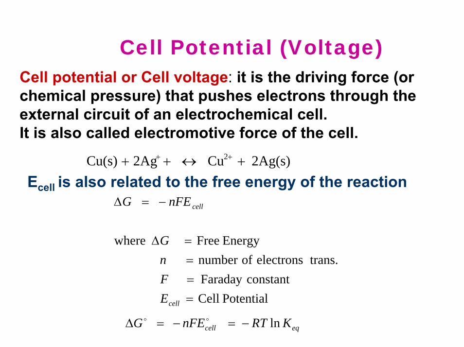
Cell Potential (Voltage)Cell potential or Cell voltage: it is the driving force (or chemical pressure) that pushes electrons through the external circuit of an electrochemical cell. It is also called electromotive force of the cell.
PotentialCellconstantFaraday
trans.electronsofnumberEnergyFreewhere
====∆
−=∆
cell
cell
EFnG
nFEG
2Ag(s)Cu 2AgCu(s) 2 +↔++ ++
Ecell is also related to the free energy of the reaction
eqcell KRTnFEG ln−=−=∆ oo

Sign Convention
AgM)(0.0200AgM)(0.0200CuCu
2Ag(s)Cu2AgCu(s)2
2
++
++ +↔+
0.412 V +-OxidAnode
Redcathode
Volt Meter
CuM)(0.0200CuM)(0.0200AgAg
Cu(s)2Ag Cu2Ag(s)2
2
++
++ +↔+
- 0.412 V +-OxidAnode
Redcathode
Volt Meter
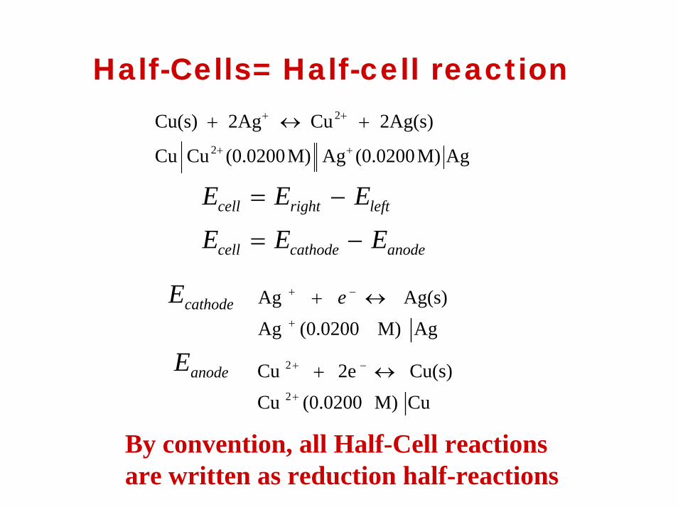
Half-Cells= Half-cell reaction
AgM)(0.0200AgM)(0.0200CuCu
2Ag(s)Cu2AgCu(s)2
2
++
++ +↔+
anodecathodecell
leftrightcell
EEE
EEE
−=
−=
cathodeEAgM)(0.0200Ag
Ag(s)Ag+
−+ ↔+ e
anodeECuM)(0.0200CuCu(s)2eCu
2
2
+
−+ ↔+
By convention, all Half-Cell reactions are written as reduction half-reactions

Current Flows and Concentrations Change

Initial Potential

Concentrations Change Until Equilibrium is Obtained
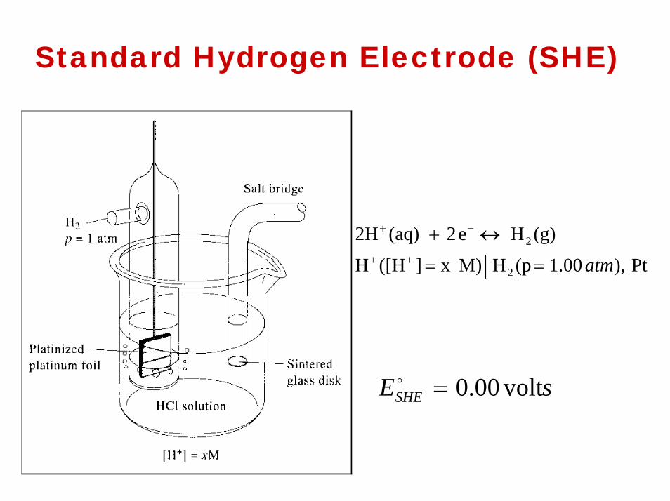
Standard Hydrogen Electrode (SHE)
Pt,)00.1(pH M)x ]([HH
(g)He2(aq)2H
2
2
atm==
↔+++
−+
sESHE volt00.0=o

Standard Cell Potentials
( )
Ag1.00) (AgSHE
Ag1.00) (Ag1.00)(Hatm1.0HPt,
2Ag(s)H22Ag(g)H
2
2
=
==
+↔+
+
++
++
a
aa VEEE anodecathodecell 799.0+=−=

Table of Standard electrode Potentials

Nernst Equation – Potentials as a function of Concentration
ba
dc
ba
dc
BADC
nEE
BADC
nFRTEE
dDcCbBaA
][][][][log0592.0
][][][][ln
−=
−=
⋅⋅⋅++↔⋅⋅⋅++
o
o
Remember -
anodecathodecell EEE −=
oooanodecathodecell EEE −=

Classification of Electrochemical methods of Analysis
• Bulk Methods: Based on phenomenon occurs in the bilk of solution. Measurement of properties of the whole solution. – Conductimetry is an example
• Interfacial Methods: Signal is a function of phenomena taking place at the electrode-solution interface. Possess wider usage.– pH measurement using a pH electrode
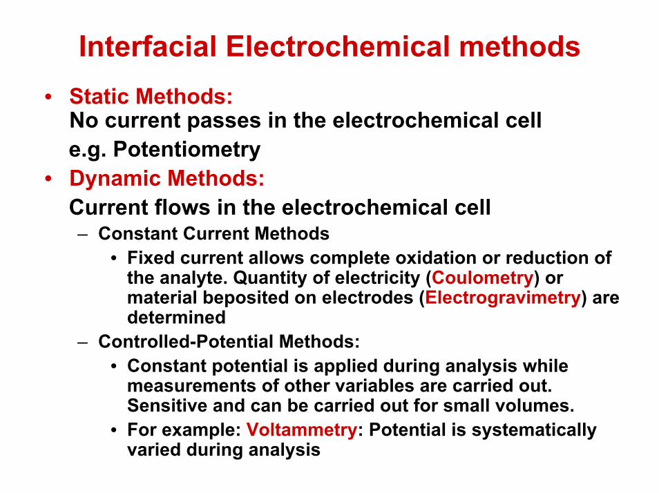
Interfacial Electrochemical methods • Static Methods:
No current passes in the electrochemical celle.g. Potentiometry
• Dynamic Methods: Current flows in the electrochemical cell – Constant Current Methods
• Fixed current allows complete oxidation or reduction of the analyte. Quantity of electricity (Coulometry) or material beposited on electrodes (Electrogravimetry) are determined
– Controlled-Potential Methods: • Constant potential is applied during analysis while
measurements of other variables are carried out. Sensitive and can be carried out for small volumes.
• For example: Voltammetry: Potential is systematically varied during analysis
Controlling and measuring Current and Potential
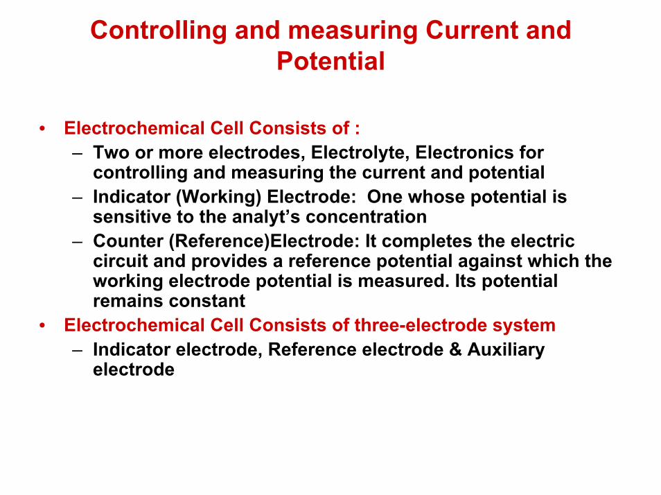
• Electrochemical Cell Consists of :– Two or more electrodes, Electrolyte, Electronics for
controlling and measuring the current and potential – Indicator (Working) Electrode: One whose potential is
sensitive to the analyt’s concentration– Counter (Reference)Electrode: It completes the electric
circuit and provides a reference potential against which the working electrode potential is measured. Its potential remains constant
• Electrochemical Cell Consists of three-electrode system– Indicator electrode, Reference electrode & Auxiliary
electrode

Comments• Passage of a current changes the
concentration of the analyte thus the potential of the counter electrode may change by time
• Counter electrode is replaced by : Reference electrode & Auxiliary electrode
• Reference electrode: No current flows through it and its potential stays constant
• Auxiliary electrode :It completes the electric circuit and allows for the current flow.

Experimental Design of the Electrochemical Cells1. Potential measurement under static conditions of no
current flow2. Potential measurement while controlling the current3. Current measurement while controlling the potential• All above measurements are based on Ohm’s law
E = iR• Instruments used for potential measurement:• Potentiometer: It measures the potential under
conditions of zero current or changes in the cell composition would take place
• iup = Eps/Rab; Eps = Power supply pot• ilow = Ecell/Rcb;• When iup = ilow = 0; no current flows• Ecell = Rcb/ Rab X Eps

iup = Eps/Rab;Eps = Power
supply pot.
ilow = Ecell/Rcb;
When iup = ilow = 0; no current flowsEcell = Rcb/ RabX Eps


Galvanostat
• Galvanostat: Device that is used to control the current in the dynamic methodsWhen R >> resistance of electrochemical
cell• Eps >> Ecell
• i = Eps / R• The potential of the working electrode is
monitored by including a reference electrode and a potentiometer.
Potentiostats
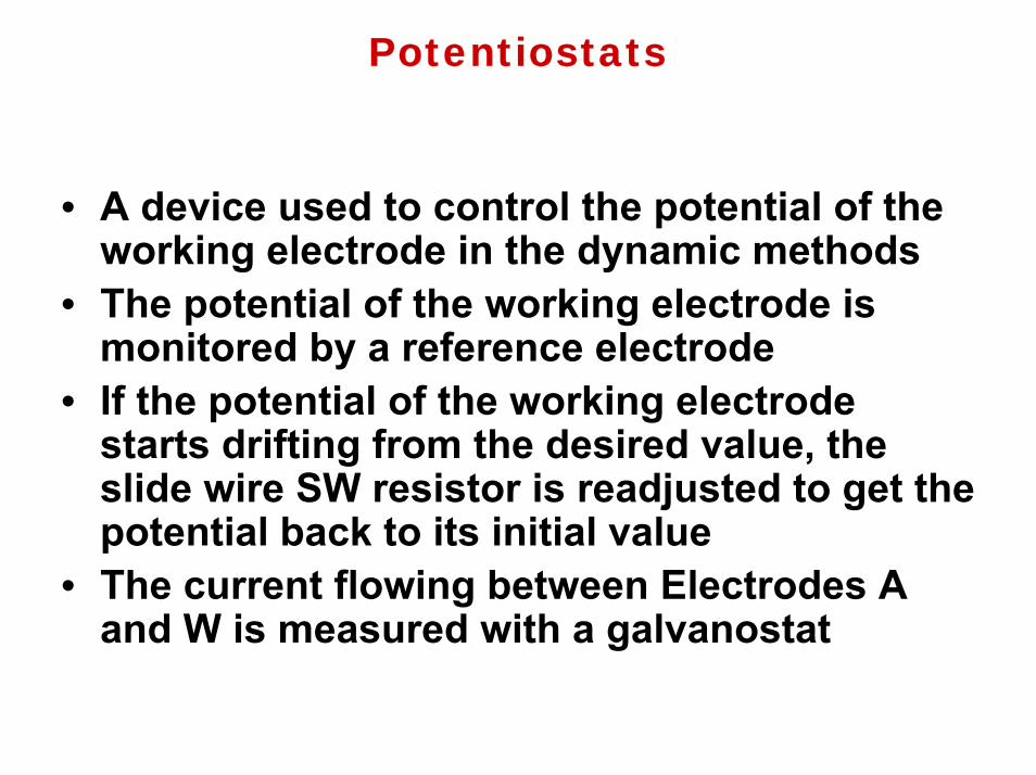
• A device used to control the potential of the working electrode in the dynamic methods
• The potential of the working electrode is monitored by a reference electrode
• If the potential of the working electrode starts drifting from the desired value, the slide wire SW resistor is readjusted to get the potential back to its initial value
• The current flowing between Electrodes A and W is measured with a galvanostat

liquid junction potential• It develops at the interface between any two ionic solutions that
differ in composition because of a difference in mobilities of the ions.
• The interface between two ionic solutions containing different electrolytes or different concentrations of the same electrolyte is called a liquidjunction.– These are designated by | in shorthand notation.
• A junction potential occurs at every liquid junction.– This puts a fundamental limitation on the
accuracy of direct potentiometric measurements, because we usually don’t know the contribution of the junction to the measured voltage.
• The junction potential is caused by unequal mobilities of the positive (+ )and negative ( - )ions.

Example
• Consider, solutions of 0.1 M HCl and 0.01 M separated by a porous membrane
• There is a net diffusion of H+ and Cl- in the direction of the arrows.
• The mobility of H+ is greater than that for Cl-, as shown by the difference in the lengths of their respective arrows.

• As a result, the solution on the right side of the membrane develops an excess of H+ and has a positive charge.
• Simultaneously, the solution on the left side of the membrane develops a negative charge due to the greater concentration of Cl-.
• The difference in potential across the membrane is called a liquid junction potential, Elj
• The magnitude of the liquid junction potential is determined by the ionic composition of the solutions on the two sides of the interface and may be as large as 30-40 mV.
• For example, a liquid junction potential of 33.09 mV has been measured at the interface between solutions of 0.1 M HCl and 0.1 M NaCl.

• Consider a solution of NaCl in contact with distilled water.
• The chloride ions have a greater mobility when the sodium and chloride ions begin to diffuse from the NaCl solution.– Chloride is less attracted to the water molecules.
• This causes a two regions to form, one rich in Cl-and one rich in Na+.
• The result is a potential difference at the junction of the NaCl and H2O phase.
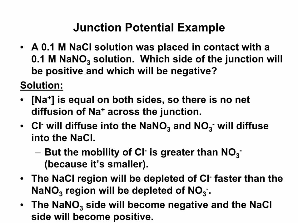
Junction Potential Example• A 0.1 M NaCl solution was placed in contact with a
0.1 M NaNO3 solution. Which side of the junction will be positive and which will be negative?
Solution:• [Na+] is equal on both sides, so there is no net
diffusion of Na+ across the junction.• Cl- will diffuse into the NaNO3 and NO3
- will diffuse into the NaCl.– But the mobility of Cl- is greater than NO3
-
(because it’s smaller).• The NaCl region will be depleted of Cl- faster than the
NaNO3 region will be depleted of NO3-.
• The NaNO3 side will become negative and the NaClside will become positive.
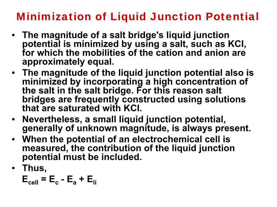
Minimization of Liquid Junction Potential• The magnitude of a salt bridge's liquid junction
potential is minimized by using a salt, such as KCI, for which the mobilities of the cation and anion are approximately equal.
• The magnitude of the liquid junction potential also is minimized by incorporating a high concentration of the salt in the salt bridge. For this reason salt bridges are frequently constructed using solutions that are saturated with KCI.
• Nevertheless, a small liquid junction potential, generally of unknown magnitude, is always present.
• When the potential of an electrochemical cell is measured, the contribution of the liquid junction potential must be included.
• Thus, Ecell = Ec - Ea + Eli
Reference Electrodes• One of the half-cells provides a known
reference potential, and the potential of the other half-cell indicates the analyte'sconcentration.
• By convention, the reference electrode is taken to be the anode; thus, the shorthand notation for a potentiometric electrochemical cell is
Reference IndicatorEcell = Eind - Eref + Elj
• The ideal reference electrode must provide a stable potential so that any change in Ecell isattributed to the indicator electrode, and, therefore, to a change in the analyte'sconcentration.

Common reference electrodes
• Standard Hydrogen Electrode (SHE) • It is rarely used for routine analytical work,
but is important because it is the reference electrode used to establish standard-state potentials for other half-reactions.
• A conventional salt bridge connects the SHE to the indicator half-cell.
• The shorthand notation for the standard hydrogen electrode is
• Pt(s), H2 (g, 1 atm) I H+ (aq, a = 1.00)
• 2H+(aq) + 2e H2(g); Eo = 0 V

Schematic diagram of the standard hydrogen electrode (SHE)
Calomel Electrodes
• Hg2Cl2(s) +2e 2Hg(l) + 2Cl- (aq)• The Nernst equation for the calomel electrode is
saturated calomel electrode• The saturated calomel electrode (SCE), which is constructed
using an aqueous solution saturated with KCI, has a potential at 25 °C of +0.2444 V.
Typical SCE• A small hole connects the two tubes, and an asbestos fiber
serves as a salt bridge to the solution in which the SCE is immersed. The stopper in the outer tube may be removed when additional saturated KCl is needed.
E = Eo Hg2Cl2/Hg - (0.05916/2) log [Cl-] 2

• The shorthand notation for the calomel electrode half-cell is
• Hg(l) | Hg2Cl2 (sat'd), KCl (aq, saturated) | |• The SCE has the advantage that the concentration of
Cl-, and, therefore, the potential of the electrode, remains constant even if the KCl solution partially evaporates.
• A significant disadvantage of the SCE is that the solubility of KCl is sensitive to a change in temperature. At higher temperatures the concentration of Cl- increases, and the electrode's potential decreases.
• Electrodes containing unsaturated solutions of KClhave potentials that are less temperature-dependent, but experience a change in potential if the concentration of KCl increases due to evaporation.
• Another disadvantage to calomel electrodes is that they cannot be used at temperatures above 80 °C.

Silver/Silver Chloride Electrodes
• Ag(s) | AgCl (sat’d, KCl (xM) ||• AgCl(s) + e- Ag(s) + Cl-(aq)• The potential of the Ag/AgCI electrode
is determined by the concentration of CI- used in its preparation.
]-log[Cl 0.05916- oE =E

Schematic diagram of Ag/AgClreference electrode
• The Ag/AgCI electrode prepared with saturated KCI is more temperature-sensitive than one prepared with an unsaturated solution of KCI.
• In comparison to the SCE the Ag/AgClelectrode has the advantage of being useful at higher temperatures.
• The Ag/AgCI electrode is more prone to reacting with solutions to form insoluble silver complexes that may plug the salt bridge between the electrode and the solution
Indicator Electrodes
• The potential of the indicator electrode in a potentiometric electrochemical cell is proportional to the concentration of analyte.
• Two classes of indicator electrodes are used in potentiometry: metallic electrodes, and membrane ion-selective electrodes.
Metallic ElectrodesElectrodes of the First Kind
• Metallic indicator electrodes in which a metal is in contact with a solution containing its ion are in general, for a metal M, in a solution of Mn+,
Mn+ + ne M
• Ecell = K- (0.059/n) log (1/[M2+] ) = K +(0.059/n) log[Mn+]
• Constant K includes the standard-state potential for the Mn+/M redox couple, the potential of the reference electrode, and the junction potential
• Electrodes of the first kind are limited to Ag, Bi, Cd, Cu, Hg, Pb, Sri, TI, and Zn.
• Many of these electrodes, such as Zn, cannot be used in acidic solutions where they are easily oxidized.
• Their usage is limited due to slow kinetics, formation of oxides and interfering reactions

Electrodes of the Second Kind
• A metal electrode can be made responsive to the concentration of anion if that anion forms a precipitate or a stable complex ion
• For example, silver forms an electrode of the second kind for halide and halide like anions.
• AgCl (s) Ag (s) + Cl-• AgI (s) Ag (s) + I-• The potential of such electrodes can be
derived as follows:


Redox Electrodes
• An inert electrode, Pt, that serves as a means to supply electrons or as a sink for electrons involved in a redox half reaction
• Pt | Fe3+ , Fe2+ ||• Fe3+ + e - Fe2+
• Ecell = Eo - 0.059/n log([Fe3+]/[Fe2+])• What is the role of Pt in this electrode?
Membrane Ion-Selective Electrodes
• The discovery, that a thin glass membrane develops a potential, called a membrane potential, when opposite sides of this membrane are in contact with solutions of different pH led to the eventual development of a whole new class of indicator electrodes called ion-selective electrodes (ISEs).
Membrane Potentials
• ISE, such as the glass pH electrode, function by using a membrane that reacts selectively with a single ion.
•• Ref Ref (sample)(sample) || [A] || [A] samplesample || Membrane Membrane || [A] [A] internalinternal || Ref || Ref internalinternal
• Ecell = E Ref (internal) – E Ref (sample) + E membrane + Elj …….(a)
• Liquid junction potential and reference electrode potentials are constant, thus any change in the cell's potential is attributed to the membrane potential.
• Current is carried through the membrane by the movement of either the analyte or an ion already present in the membrane's matrix.
•

• The membrane potential is given by:• Emem = Easym -(RT/zF) ln ([A] internal /[A] samp) ….(b)• Easym = Asymmetric potential : The
membrane potential that develops when the concentrations on both sides are equal.
• Substituting eq. (b)into eq. (a) gives • Ecell = K + (0.059/z) log [A) sample• This equation applies to all types of ISE’s.
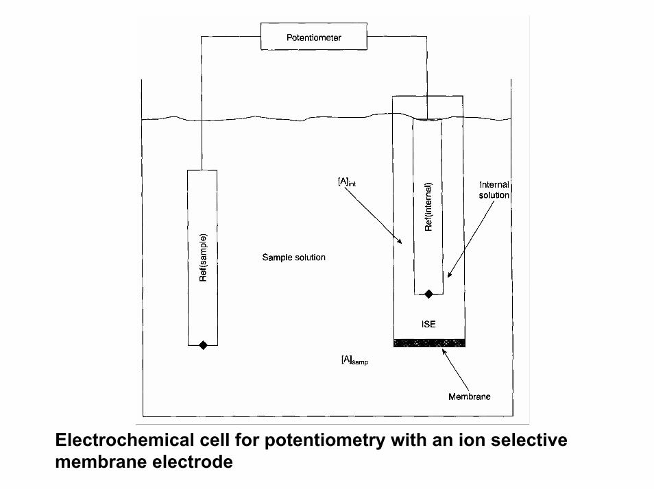
Electrochemical cell for potentiometry with an ion selective membrane electrode

Developing membrane potential at the surface of Ca-SE

Mechanism of Ca-membrane selective electrode
• As Ca2+ migrates from the region of high activity to the region of low activity, positive charge is built up on the low-activity side. Eventually the charge buildup prevents further migration of Ca2+ to the positively charged side.
• This is the same thing that happens at a liquid junction, and a constant potential difference across the junction or membrane is reached.
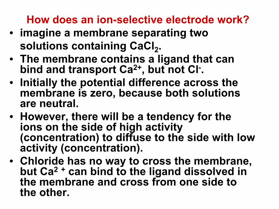
How does an ion-selective electrode work?• imagine a membrane separating two
solutions containing CaCl2.• The membrane contains a ligand that can
bind and transport Ca2+, but not Cl-. • Initially the potential difference across the
membrane is zero, because both solutions are neutral.
• However, there will be a tendency for the ions on the side of high activity (concentration) to diffuse to the side with low activity (concentration).
• Chloride has no way to cross the membrane, but Ca2 + can bind to the ligand dissolved in the membrane and cross from one side to the other.

Selectivity of Membranes
• The membrane potential is proportional to the concentration of all ions in the sample solution capable of interacting at the membrane's active sites
)I/z
Az
[I] IA,K [A] (log A
z0.05916 K cellE ++=
KA,I = Selectivity coefficient
KA,I =
and are the concentrations of analyte interferentyielding identical cell potentials
When KA,I is 1 the membrane responds equally to the analyte and interferent
zIzA
E
E
IA
/][][
EA][EI ][

Plot of cell potential versus the log of the analyt’s concentration in the presence of a fixed concentration of interferent showing the determination of the selectivity coefficient
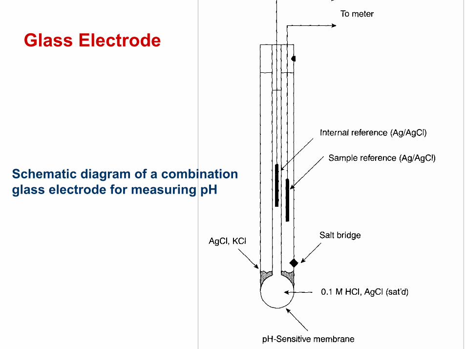
Glass Electrode
Schematic diagram of a combination glass electrode for measuring pH
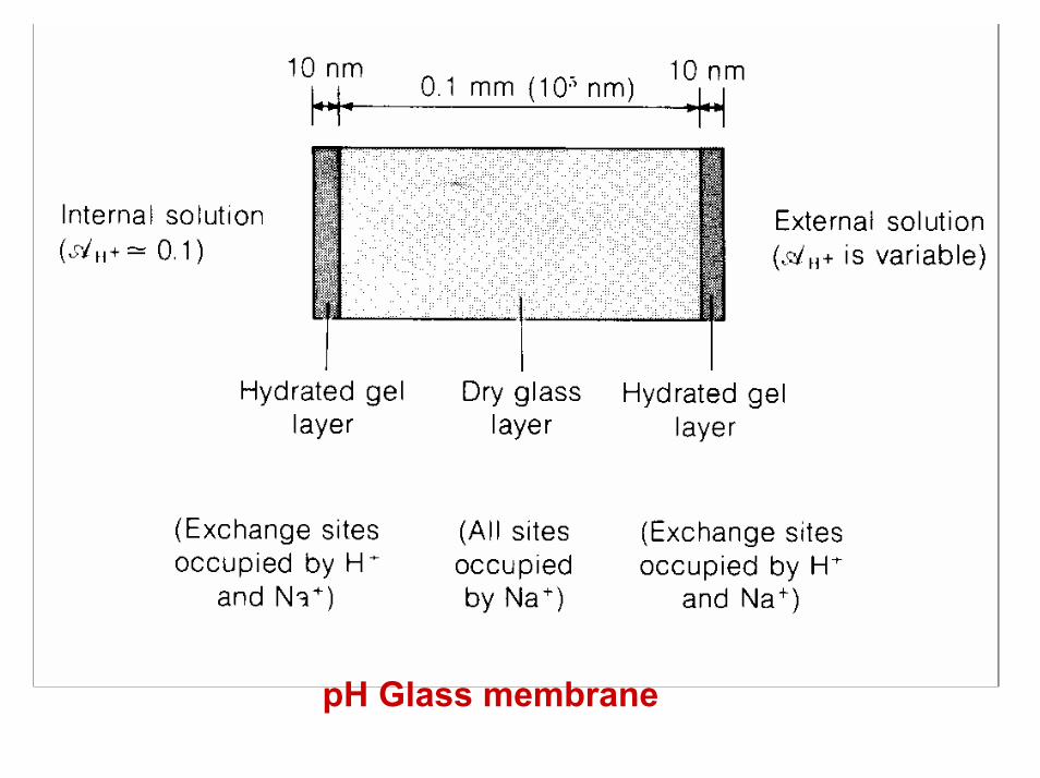
pH Glass membrane

• Hydration of the glass membrane results in the formation of negatively charged sites, G-, that are part of the glass membrane's silica framework.
• Sodium ions, which are able to move through the hydrated layer, serve as the counter ions.
• Hydrogen ions from solution diffuse into the membrane and, since they bind more strongly to the glass than does Na+, displace the sodium ions
H+(aq) + G-Na+(s) G-H+(s) + Na+(aq)giving rise to the membrane's selectivity for H+.
The transport of charge across the membrane is carried by theNa+ ions. The potential of glass electrodes
Ecell = K + 0.05916 log [H+]
Mechanism of membrane potential at the glass membrane surface

Combined Glass Electrode

Alkaline (Sodium) Error• When the concentration of H+ is very low and
that of Na+ is high the electrode responds to Na+ as well as to H+. This arise s because Na+
can participate in ion exchange with the hydrated gel layer.
• To reduce the alkaline error, lithium has largely replaced sodium in glass electrodes.
Acid Error• In very acidic solutions, the measured pH is
higher than the actual pH. The reason for this is not clear, but it may be related to the decreased activity of water in concentrated acid solution.
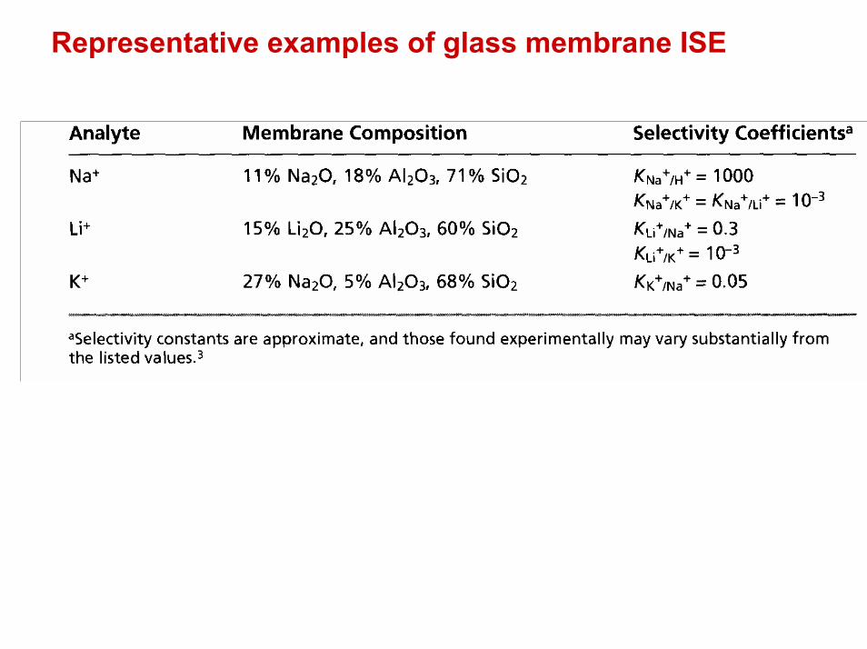
Representative examples of glass membrane ISE
Crystalline solid –state ion-selective electrode
• Electrodes based on sparingly soluble inorganic crystalline material: Ag2S or mixture of Ag2S and either a second silver salt or another metal sulfide
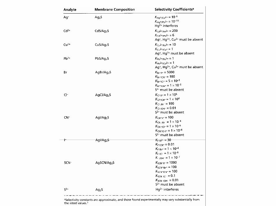
• Representative examples of polycrystalline ISE are listed in the following table
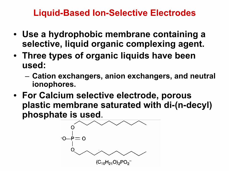
Liquid-Based Ion-Selective Electrodes
• Use a hydrophobic membrane containing a selective, liquid organic complexing agent.
• Three types of organic liquids have been used:– Cation exchangers, anion exchangers, and neutral
ionophores. • For Calcium selective electrode, porous
plastic membrane saturated with di-(n-decyl) phosphate is used.

Schematic diagram of a calcium liquid membrane ISE


Representative examples of liquid-based ISE

Schematic diagram of a gas –sensing membrane electrode
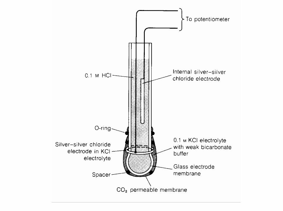
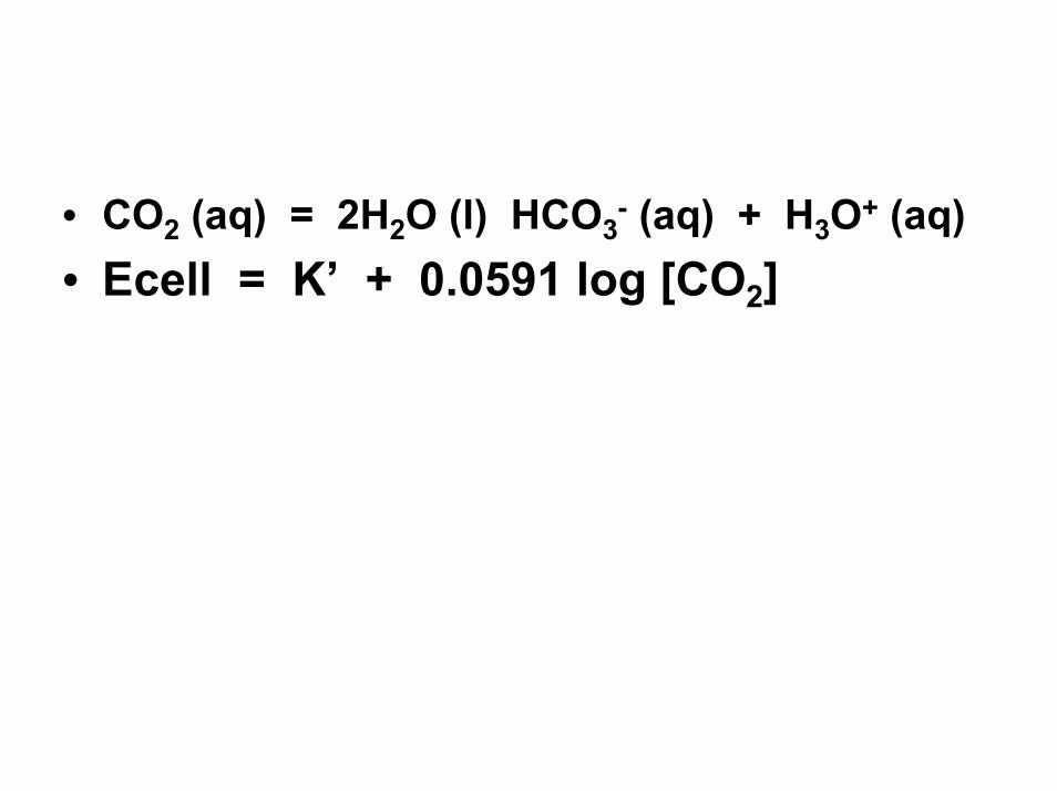
• CO2 (aq) = 2H2O (l) HCO3- (aq) + H3O+ (aq)
• Ecell = K’ + 0.0591 log [CO2]

Characteristics of gas-sensing membrane electrodes
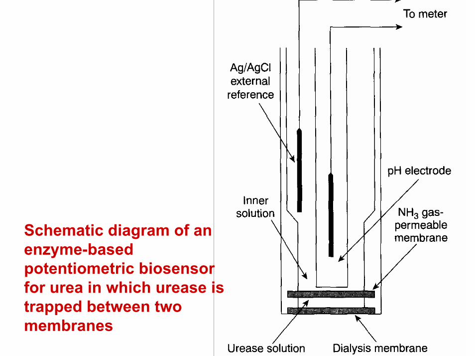
Schematic diagram of an enzyme-based potentiometric biosensor for urea in which urease is trapped between two membranes
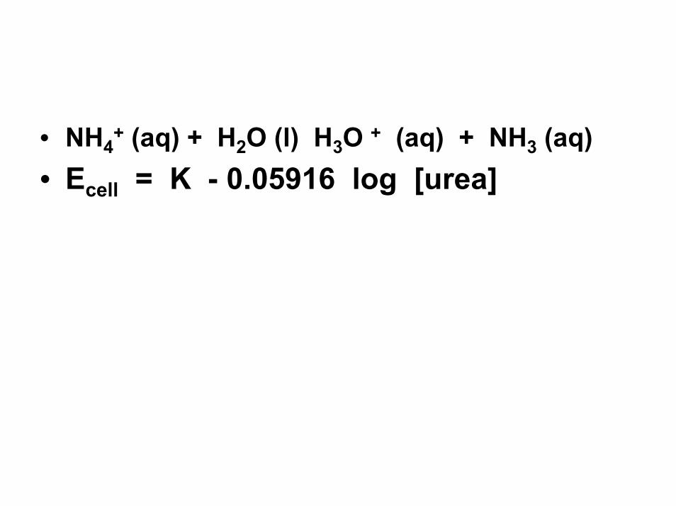
• NH4+ (aq) + H2O (l) H3O + (aq) + NH3 (aq)
• Ecell = K - 0.05916 log [urea]

Schematic diagram of a second enzyme-based potentiometric biosensor for urea in which urease is immobilized in a polymer matrix
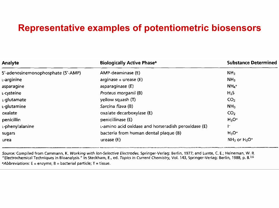
Representative examples of potentiometric biosensors

Quantitative Applications Activity versus Concentration

Quantitative Analysis using external standards

Quantitative analysis using the method of Standard Additions
• Because of the difficulty of maintaining a constant matrix for samples and standards, many quantitative potentiometric methods use the method of standard additions.
• A sample of volume, Vx, and analyte concentration, Cx, is transferred to a sample cell, and the potential, (Ecell)x, measured.
• A standard addition is made by adding a small volume, Vs, of a standard containing a known concentration of analyte, Cs, to the sample, and the potential, (Ecell)s, measured. Provided that Vs is significantly smaller than Vx, the change in sample matrix is ignored, and the analyte's activity coefficient remains constant.

Example
• The concentration of Ca2+ in a sample of sea water is determined using a Ca ion-selective electrode and a one-point standard addition. A 10.00-mL sample is transferred to a 100-mL volumetric flask and diluted to volume. A 50.00-mL aliquot of sample is placed in a beaker with the Ca ion-selective electrode and a reference electrode, and the potential is measured as -0.05290 V. A 1.00-mL aliquot of a 5.00 x 10⁻² M standard solution of Ca2+ is added, and a potential of -0.04417 V is measured. What is the concentration of Ca2+
in the sample of sea water?

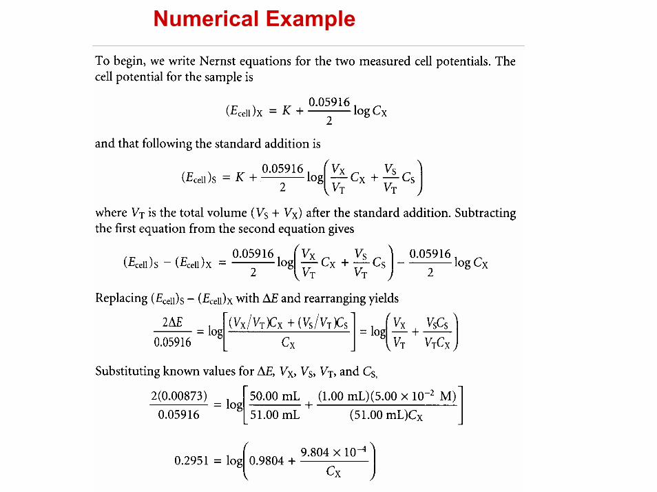
Numerical Example

Numerical example