uniswitch medium voltage switchgear - abb ltd · 1.4 construction of the switchgear and main...
TRANSCRIPT

UNIS 6 GB
1
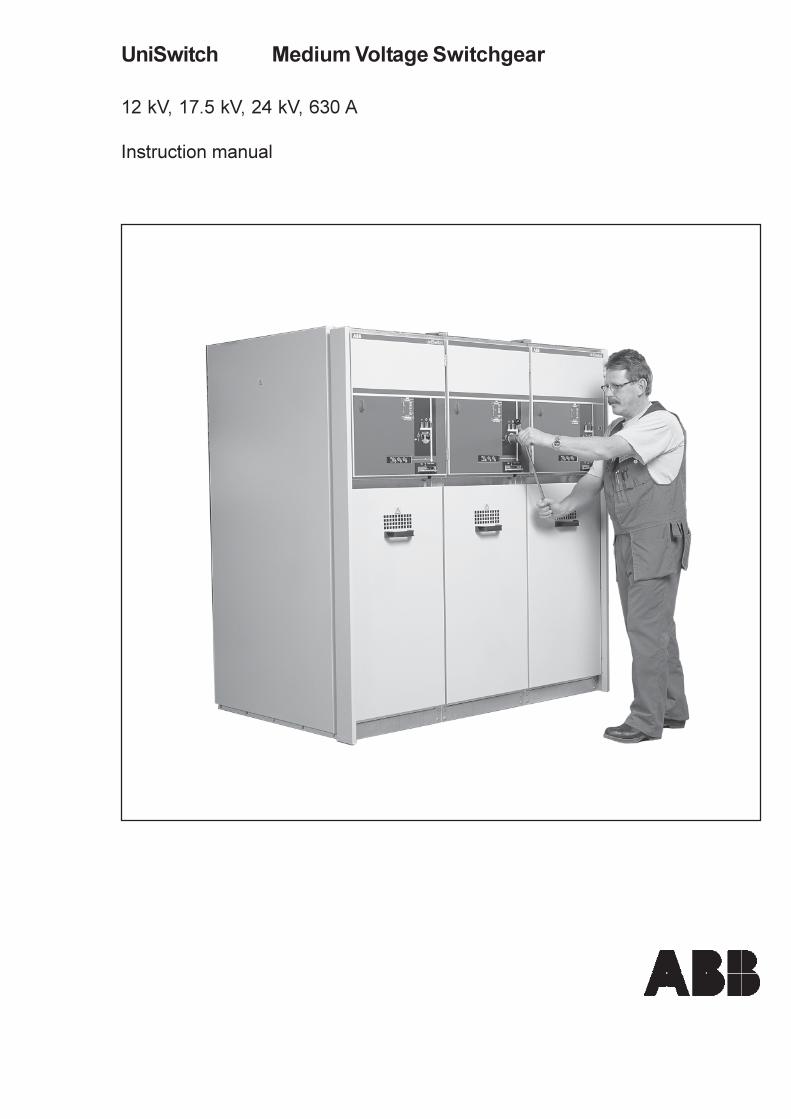
UniSwitch Medium Voltage Switchgear
12 kV, 17.5 kV, 24 kV, 630 A
Instruction manual
UNIS 6 GB
1
UniSwitch Medium Voltage Switchgear
12 kV, 17.5 kV, 24 kV, 630 A
Instruction manual
UNIS 6 GB
2
UniSwitch
Instruction manual
Content1. UniSwitch Switchgear System Description ........................................ 3
1.1 Introduction ............................................................................. 31.2 Service conditions ................................................................... 31.3 Technical details ..................................................................... 41.4 Construction of the switchgear and
main components ................................................................... 5
2. Interlocking ....................................................................................... 72.1 General ................................................................................... 72.2 Interlocking unit ....................................................................... 72.3 Normal interlocking ................................................................. 82.4 Additional interlocking ............................................................. 8
3. Method of Operation ����������������� ............. 93.1 Manual operation of the SFG
switch-connector ..................................................................... 93.1.1 Closing the SFG switch-disconnector .......................... 93.1.2 Opening the SFG switch-disconnector ......................... 93.1.3 Operating the SFG switch-disconnector
to the earthed position ............................................... 103.1.4 Opening the SFG switch-disconnector
from the earthed position............................................ 103.2 Opening the doors ................................................................. 11
4. Voltage Indicating Systems ............................................................ 124.1 General ................................................................................. 124.2 Integrated voltage indicating system CL-497 ......................... 124.3 Separable voltage indicating system CL-498 ......................... 13
5. Service and Maintenance ................................................................ 14
6. Trouble shooting .............................................................................. 16
7. Recycling Instructions ..................................................................... 187.1 General ................................................................................. 187.2 Packing materials ................................................................. 187.3 Materials used in production ................................................. 19
UNIS 6 GB
3
1. UniSwitch SwitchgearSystem Description
1.1 Introduction
The UniSwitch switchgear system is an air insulated,metal enclosed, cubicle type switchgear arrangement.The system includes several standardised cubicleswhich can be delivered either as a complete switch-gear or as individual cubicles.
The UniSwitch switchgear system uses standard com-ponents such as switch-disconnectors, SF6- or vacuumcircuit-breakers, earthing switches, instrument trans-formers and secondary apparatus. By combining thestandard components, a system which offers a widerange of different device arrangements can be made.
The UniSwitch switchgear system is designed for usein general and industrial applications in 3,6 � 24 kVelectrical distribution networks.
The system complies with the following IEC standards:
IEC 60298 A.C. metal-enclosed switchgear andcontrolgear for rated voltages above1 kV and up to and including 52 kV(1990), Am1 (1994)
IEC 60694 Common specifications for high-voltageswitchgear and controlgear standards(1996)
IEC 60044-1 Instrument transformers� Part 1: Current transformers
IEC 60044-2 Instrument transformers� Part 2: Inductive voltage transformers
IEC 60056 High-voltage alternating-current circuit-breakers (1987)
IEC 60129 Alternating current disconnectors andearthing switches (1984), Am1 (1992),Am2 (1996)
IEC 60265-1 High-voltage switchesPart 1: Switches for rated voltages above1 kV and less than 52 kV (1998)
IEC 60420 High-voltage alternating current switch-fuse combinations (1990)
IEC 60529 Degrees of protection provided by enclo-sures (IP Code) (1989)
1.2 Service conditions
The switchgear is intended for use in normal indoorservice conditions as defined in table 1 below fromthe relevant IEC standards. If the conditions wherethe switchgear are to be installed deviate from thenormal service conditions defined in the IEC standards,it has to be agreed separately with the manufacturer.
Table 1.Normal indoor service conditions accordingto IEC standards.
Ambient air temperatureMaximum + 40°CMaximum 24 h average temperature + 35°CMinimum 24 h average temperature - 5°CRecommended (minimum) + 5°C
Altitude above sea levelMaximum 1000 m
The conditions of humidityAverage value of relative humidity (24 h) < 95 %Average value of relative humidity (1 month) < 90 %
PollutionThe ambient air is not significantly polluted by dust,smoke, corrosive and/or flammable gases, vaporsor salt
UniSwitchInstruction manual
UNIS 6 GB
4
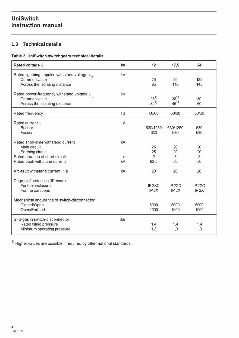
1.3 Technical details
Table 2. UniSwitch switchgears technical details
Rated voltage Ur
kV 12 17,5 24
Rated lightning impulse withstand voltage Up
kVCommon value 75 95 125Across the isolating distance 85 110 145
Rated power-frequency withstand voltage Ud
kVCommon value 281) 381) 50Across the isolating distance 321) 451) 60
Rated frequency Hz 50/60 50/60 50/60
Rated current Ir
ABusbar 630/1250 630/1250 630Feeder 630 630 630
Rated short-time withstand current kAMain circuit 25 20 20Earthing circuit 25 20 20
Rated duration of short circuit s 2 3 3Rated peak withstand current kA 62,5 50 50
Arc-fault withstand current, 1 s kA 20 20 20
Degree of protection (IP-code)For the enclosure IP 2XC IP 2XC IP 2XCFor the partitions IP 2X IP 2X IP 2X
Mechanical endurance of switch-disconnectorClosed/Open 5000 5000 5000Open/Earthed 1000 1000 1000
SF6-gas in switch-disconnector BarRated filling pressure 1,4 1,4 1,4Minimum operating pressure 1,3 1,3 1,3
1) Higher values are possible if required by other national standards.
UniSwitchInstruction manual
UNIS 6 GB
5
1.4 Construction of the switchgear andmain components
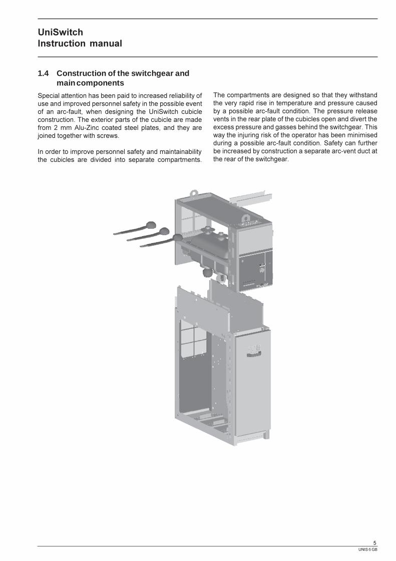
Special attention has been paid to increased reliability ofuse and improved personnel safety in the possible eventof an arc-fault, when designing the UniSwitch cubicleconstruction. The exterior parts of the cubicle are madefrom 2 mm Alu-Zinc coated steel plates, and they arejoined together with screws.
In order to improve personnel safety and maintainabilitythe cubicles are divided into separate compartments.
The compartments are designed so that they withstandthe very rapid rise in temperature and pressure causedby a possible arc-fault condition. The pressure releasevents in the rear plate of the cubicles open and divert theexcess pressure and gasses behind the switchgear. Thisway the injuring risk of the operator has been minimisedduring a possible arc-fault condition. Safety can furtherbe increased by construction a separate arc-vent duct atthe rear of the switchgear.
UniSwitchInstruction manual

UNIS 6 GB
6
Each cubicle rear plate has three arc-pressure reliefvents:
A. The upper arc-pressure relief vent is for the busbarchamber.
B. The switch-disconnector has its own arc-pressurerelief vent.
C. The lower arc-pressure relief vent is for the circuit-breaker and cable compartment.
The cubicle is divided into the following compartments.
1. Main Busbar CompartmentThe air insulated busbar compartment is situated in thetop of the cubicle and usually runs through the wholeswitchgear. A measuring or sectionalising cubicle situ-ated in the middle of the switchgear divides the mainbusbar compartment.
2. Disconnector CompartmentThe three position switch-disconnector is locatedbetween the main busbar and cable compartments. Itsepoxy resin shell forms a SF
6-gas filled space in which
the switches electrical parts are situated.
3. Cable CompartmentAbout 75 % of the cubicle volume is reserved forthe incoming/feeder cable connections, fuses, earthingswitches or instrument transformers.
4. Control and Secondary Apparatus CompartmentThe compartment includes space for the switch-disconnector and earthing switch operating mechanisms,and mechanical interlocks with position indicators. Otheradditional components such as auxiliary contacts, tripcoils, voltage indicators and relays can be fitted in thiscompartment. It is also usual to fit the secondary wiring,terminal blocks and cable channels in this compartment.
5. Circuit breaker compartmentThe circuit breaker (SF
6 or vacuum) is located to the left of
the cable compartment.
UniSwitchInstruction manual
A
B
C
1
2
35
4
UNIS 6 GB
7
2. Interlocking
2.1 General
Interlocking includes:
1) Normal interlocking which is fitted as standard inevery cubicle.
2) Additional interlocking which are optional and to bechosen by the customer.
The purpose of the interlocking is to prevent incorrectoperation of the switch-disconnector and earthing switchand ensure personnel safety. The interlocking is in opera-tion even if the doors to the cable and control compart-ments are open.
The interlocking applies also to the earthing switches EFand EM, which are used for earthing bottom of the fusesand current transformers. These switches are mechani-cally connected to the operating device of SFG switch-disconnector and they are operating simultaneously withthe SFG when it is operated between open and earthedposition.
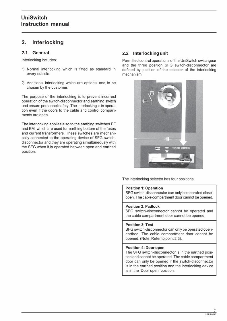
2.2 Interlocking unit
Permitted control operations of the UniSwitch switchgearand the three position SFG switch-disconnector aredefined by position of the selector of the interlockingmechanism.
The interlocking selector has four positions:
Position 1: OperationSFG switch-disconnector can only be operated close-open. The cable compartment door cannot be opened.
Position 2: PadlockSFG switch-disconnector cannot be operated andthe cable compartment door cannot be opened.
Position 3: TestSFG switch-disconnector can only be operated open-earthed. The cable compartment door cannot beopened. (Note: Refer to point 2.3).
Position 4: Door openThe SFG switch-disconnector is in the earthed posi-tion and cannot be operated. The cable compartmentdoor can only be opened if the switch-disconnectoris in the earthed position and the interlocking deviceis in the �Door open� position.
UniSwitchInstruction manual
UNIS 6 GB
8
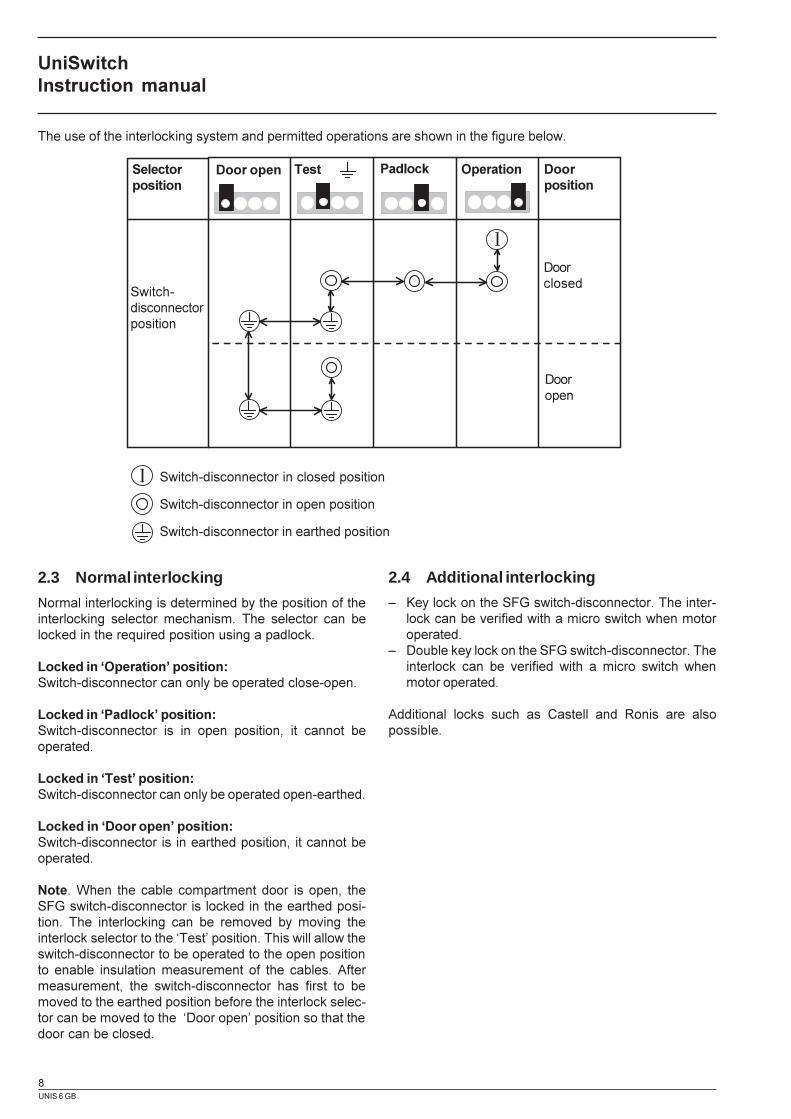
The use of the interlocking system and permitted operations are shown in the figure below.
2.3 Normal interlocking
Normal interlocking is determined by the position of theinterlocking selector mechanism. The selector can belocked in the required position using a padlock.
Locked in �Operation� position:Switch-disconnector can only be operated close-open.
Locked in �Padlock� position:Switch-disconnector is in open position, it cannot beoperated.
Locked in �Test� position:Switch-disconnector can only be operated open-earthed.
Locked in �Door open� position:Switch-disconnector is in earthed position, it cannot beoperated.
Note. When the cable compartment door is open, theSFG switch-disconnector is locked in the earthed posi-tion. The interlocking can be removed by moving theinterlock selector to the �Test� position. This will allow theswitch-disconnector to be operated to the open positionto enable insulation measurement of the cables. Aftermeasurement, the switch-disconnector has first to bemoved to the earthed position before the interlock selec-tor can be moved to the �Door open� position so that thedoor can be closed.
2.4 Additional interlocking
� Key lock on the SFG switch-disconnector. The inter-lock can be verified with a micro switch when motoroperated.
� Double key lock on the SFG switch-disconnector. Theinterlock can be verified with a micro switch whenmotor operated.
Additional locks such as Castell and Ronis are alsopossible.
UniSwitchInstruction manual
Selectorposition
Switch-disconnectorposition
Door open Test Padlock Operation Doorposition
Doorclosed
Dooropen
Switch-disconnector in closed position
Switch-disconnector in open position
Switch-disconnector in earthed position
UNIS 6 GB
9
3. Method of Operation
3.1. Manual operation of the SFG switch-disconnector
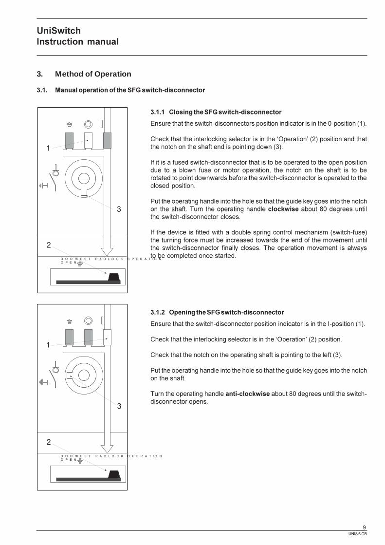
3.1.1 Closing the SFG switch-disconnector
Ensure that the switch-disconnectors position indicator is in the 0-position (1).
Check that the interlocking selector is in the �Operation� (2) position and thatthe notch on the shaft end is pointing down (3).
If it is a fused switch-disconnector that is to be operated to the open positiondue to a blown fuse or motor operation, the notch on the shaft is to berotated to point downwards before the switch-disconnector is operated to theclosed position.
Put the operating handle into the hole so that the guide key goes into the notchon the shaft. Turn the operating handle clockwise about 80 degrees untilthe switch-disconnector closes.
If the device is fitted with a double spring control mechanism (switch-fuse)the turning force must be increased towards the end of the movement untilthe switch-disconnector finally closes. The operation movement is alwaysto be completed once started.
3.1.2 Opening the SFG switch-disconnector
Ensure that the switch-disconnector position indicator is in the I-position (1).
Check that the interlocking selector is in the �Operation� (2) position.
Check that the notch on the operating shaft is pointing to the left (3).
Put the operating handle into the hole so that the guide key goes into the notchon the shaft.
Turn the operating handle anti-clockwise about 80 degrees until the switch-disconnector opens.
UniSwitchInstruction manual
D O O RO P E N
T E S T P A D L O C K O P E R A T I O N
1
2
3
D O O RO P E N
T E S T P A D L O C K O P E R A T I O N
1
2
3
UNIS 6 GB
10
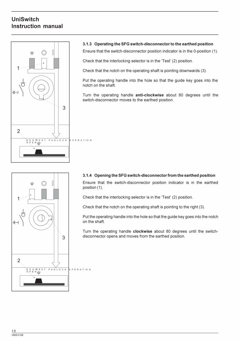
3.1.3 Operating the SFG switch-disconnector to the earthed position
Ensure that the switch-disconnector position indicator is in the 0-position (1).
Check that the interlocking selector is in the �Test� (2) position.
Check that the notch on the operating shaft is pointing downwards (3).
Put the operating handle into the hole so that the guide key goes into thenotch on the shaft.
Turn the operating handle anti-clockwise about 80 degrees until theswitch-disconnector moves to the earthed position.
3.1.4 Opening the SFG switch-disconnector from the earthed position
Ensure that the switch-disconnector position indicator is in the earthedposition (1).
Check that the interlocking selector is in the �Test� (2) position.
Check that the notch on the operating shaft is pointing to the right (3).
Put the operating handle into the hole so that the guide key goes into the notchon the shaft.
Turn the operating handle clockwise about 80 degrees until the switch-disconnector opens and moves from the earthed position.
UniSwitchInstruction manual
D O O RO P E N
T E S T P A D L O C K O P E R A T I O N
1
2
3
D O O RO P E N
T E S T P A D L O C K O P E R A T I O N
1
2
3
UNIS 6 GB
11
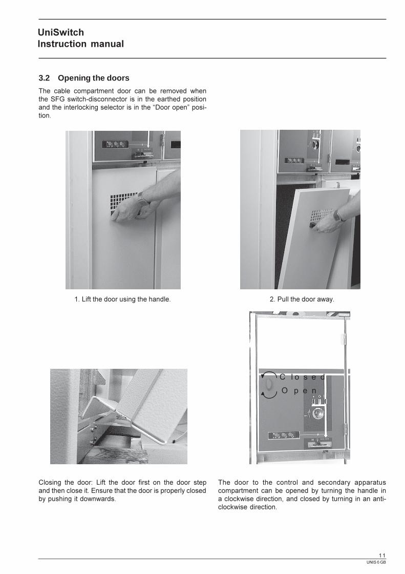
3.2 Opening the doors
The cable compartment door can be removed whenthe SFG switch-disconnector is in the earthed positionand the interlocking selector is in the �Door open� posi-tion.
Closing the door: Lift the door first on the door stepand then close it. Ensure that the door is properly closedby pushing it downwards.
1. Lift the door using the handle. 2. Pull the door away.
The door to the control and secondary apparatuscompartment can be opened by turning the handle ina clockwise direction, and closed by turning in an anti-clockwise direction.
UniSwitchInstruction manual
O p e n
C l o s e d

UNIS 6 GB
12
4. Voltage Indicating Systems
4.1 General
UniSwitch cubicles can be, if required, fitted with voltageindicating systems in accordance with IEC 61243-5 stand-ard to give an indication of whether the cubicle is live ordead.
4.2 Integrated voltage indicating systemCL-497
The integrated voltage indicating system is equippedwith fixed phase LED-lamps which are marked L1, L2and L3.
In accordance with standard IEC 61243-5, the voltageindicating device is to show that the cubicle is live if thephase voltage U
v is between 0,45 x U
n < U
v < 1,2 U
n(where U
n is the switchgears rated 3-phase voltage). On
the otherhand, the voltage indicator is to show theswitchgear is dead if the phase voltage U
v < 0,10 x U
n.
The voltage state of the cubicle is to be indicated withlamps which flash at a frequency of more than 1 Hz.
The integrated voltage indicator device will operate reli-ably over a temperature range of - 25° � + 50 °C.
Each phase of the integrated voltage indicating systemhas a test point on the front panel, which can be used toperform phase comparison and testing of the voltageindicator.
If a cubicle fitted with an integrated voltage indicatingsystem is installed in a place with brighter than normallighting, or if the voltage indicator is subject to directsunlight, the device can be fitted with a shade to improvevisibility.
If the LED-lamps on the voltage indicating system arenot lit, but the cubicle is suspected as being live, theoperation of the LED-lamps can be verified by usinga CATU CL-1-05100 test device. The terminals of the testdevice are to be connected to the test points betweenphases L1 - L2 on the voltage indicating system, andthe lamps given a current pulse by pressing the handleon the test device. The LED-lamps on phases L1 andL2 should flash if they are intact. The test point betweenL1 - L3 and L2 - L3 can be tested in the same way. TheCATU CL-1-05100 is an optional accessory.
UniSwitchInstruction manual

UNIS 6 GB
13
4.3 Separable voltage indicating systemCL-498
A separable voltage indicating system gives the user thepossibility to check the voltage state of the cubicle byusing a voltage indicator in accordance to standard IEC61243-5 for which the CL-498 has a connection point onthe front panel for each phase. The connection pointterminals are marked L1, L2 and L3. Earthed terminalsare marked with an earthing symbol.
Designation Input impedance Xc
Load capacitance Cs
Electrical threshold conditions atof the VDS of the indicator of the coupling system the interface
Xcmin X
cmax C
smin C
smax I
tmin I
tmax U
tmin U
tmax
MW MW pF pF mA mA V V
HR 36 43,2 74 88 1,62 2,5 70 90
The separable voltage indicating system, together withthe standard IEC 61243-5 voltage indicator has to showthat the cubicle is live if the phase voltage U
v is between
0,45 x Un < U
v < 1,2 U
n (U
n switchgear 3-phase rated
voltage). On the other hand the system is to indicatethat the cubicle is dead if the voltage U
v < 0,10 x U
n.
The voltage state of the cubicle is to be indicatedwith lamps, which flash at a frequency of more than 1 Hz.
The CL-498 device is high resistance system in accord-ance with standard IEC61243-5, and has operational limitvalues as detailed in table 3 below.
Table 3. Characteristics of separable voltage detecting systems (all values refer to 50 Hz).
The separable voltage indicating system will operatereliably over a temperature range of - 25°� + 50°C.
Short-circuit plugs shall not be used in systems withresonant earthed or insulated neutrals.
UniSwitchInstruction manual
UNIS 6 GB
14
5. Service and Maintenance
Before carrying out any maintenance work ensurethat no remote control is possible.Remove all control inputs and check that theinstrument transformer secondaries are opencircuit. All cables are to either be removed orearthed in the cubicles where work is to be carriedout.
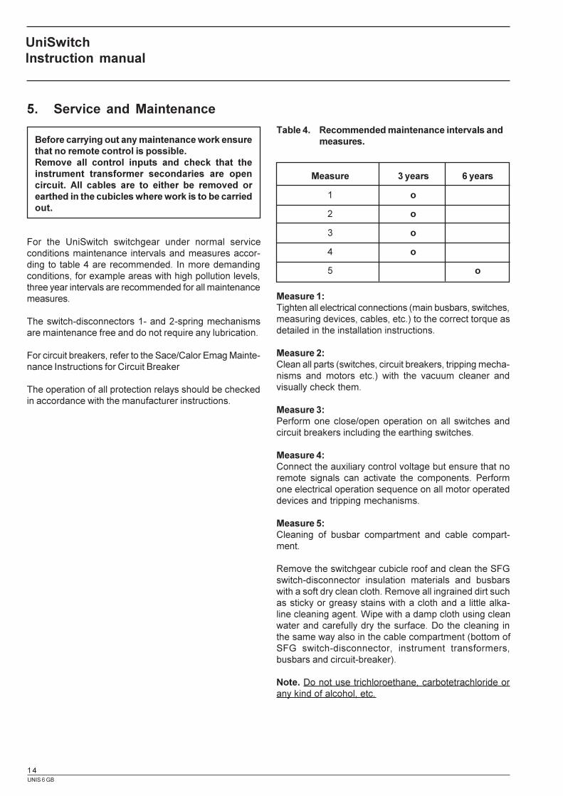
For the UniSwitch switchgear under normal serviceconditions maintenance intervals and measures accor-ding to table 4 are recommended. In more demandingconditions, for example areas with high pollution levels,three year intervals are recommended for all maintenancemeasures.
The switch-disconnectors 1- and 2-spring mechanismsare maintenance free and do not require any lubrication.
For circuit breakers, refer to the Sace/Calor Emag Mainte-nance Instructions for Circuit Breaker
The operation of all protection relays should be checkedin accordance with the manufacturer instructions.
Measure 1:Tighten all electrical connections (main busbars, switches,measuring devices, cables, etc.) to the correct torque asdetailed in the installation instructions.
Measure 2:Clean all parts (switches, circuit breakers, tripping mecha-nisms and motors etc.) with the vacuum cleaner andvisually check them.
Measure 3:Perform one close/open operation on all switches andcircuit breakers including the earthing switches.
Measure 4:Connect the auxiliary control voltage but ensure that noremote signals can activate the components. Performone electrical operation sequence on all motor operateddevices and tripping mechanisms.
Measure 5:Cleaning of busbar compartment and cable compart-ment.
Remove the switchgear cubicle roof and clean the SFGswitch-disconnector insulation materials and busbarswith a soft dry clean cloth. Remove all ingrained dirt suchas sticky or greasy stains with a cloth and a little alka-line cleaning agent. Wipe with a damp cloth using cleanwater and carefully dry the surface. Do the cleaning inthe same way also in the cable compartment (bottom ofSFG switch-disconnector, instrument transformers,busbars and circuit-breaker).
Note. Do not use trichloroethane, carbotetrachloride orany kind of alcohol, etc.
Measure 3 years 6 years
1 o
2 o
3 o
4 o
5 o
Table 4. Recommended maintenance intervals andmeasures.
UniSwitchInstruction manual
UNIS 6 GB
15
It is recommenced that the dry and clean surfaces arecovered with a thin layer of silicone liquid such as DC200/100CS or similar.
Tools required:Screwdriver, hand tools for 10 mm screws, M10 (M8)torque wrench, vacuum cleaner, cleaning cloths,mild alkaline cleaning agent, clean water, siliconliquid, protection relay instruction manual and testequipment.
UniSwitchInstruction manual
Check that there are no visible signs or damagefrom partial discharge.There should also not be any visible signs ofconnection joints overheating.All components should perform perfectly andany faulty components are to be replaced.
UNIS 6 GB
16
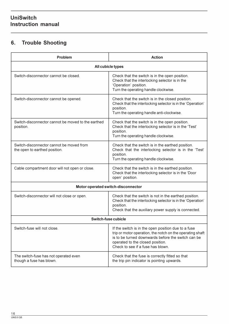
Problem Action
All cubicle types
Switch-disconnector cannot be closed. Check that the switch is in the open position.Check that the interlocking selector is in the�Operation� position.Turn the operating handle clockwise.
Switch-disconnector cannot be opened. Check that the switch is in the closed position.Check that the interlocking selector is in the �Operation�position.Turn the operating handle anti-clockwise.
Switch-disconnector cannot be moved to the earthed Check that the switch is in the open position.position. Check that the interlocking selector is in the �Test�
position.Turn the operating handle clockwise.
Switch-disconnector cannot be moved from Check that the switch is in the earthed position.the open to earthed position. Check that the interlocking selector is in the �Test�
position.Turn the operating handle clockwise.
Cable compartment door will not open or close. Check that the switch is in the earthed position.Check that the interlocking selector is in the �Dooropen� position.
Motor operated switch-disconnector
Switch-disconnector will not close or open. Check that the switch is not in the earthed position.Check that the interlocking selector is in the �Operation�position.Check that the auxiliary power supply is connected.
Switch-fuse cubicle
Switch-fuse will not close. If the switch is in the open position due to a fusetrip or motor operation, the notch on the operating shaftis to be turned downwards before the switch can beoperated to the closed position.Check to see if a fuse has blown.
The switch-fuse has not operated even Check that the fuse is correctly fitted so thatthough a fuse has blown. the trip pin indicator is pointing upwards.
6. Trouble Shooting
UniSwitchInstruction manual

UNIS 6 GB
17
Problem Action
Circuit breaker cubicle
The cable compartment door will not open. Check that the switch is in the earthed position.Check the interlocking selector is in the �Dooropen� position.Remove the key from the circuit breaker before openingor closing the door.
The circuit breaker will not go to the closed Ensure that the closing spring is fully charged,position. and that the interlocking coil is not energised.
Check that the circuit breaker key is in place and turnedto the correct operating position.Check that the circuit breakers auxiliary voltageplug is properly locked into the socket.Check that the control pin is on its position (HAD-US).
Instrument Transformers
Secondary measurements from the current Check that all shorting links on the secondary terminalstransformers are not possible. of the current transformers have been removed.
Check the connections.
UniSwitchInstruction manual
UNIS 6 GB
18
7. Recycling Instructions
7.1 General
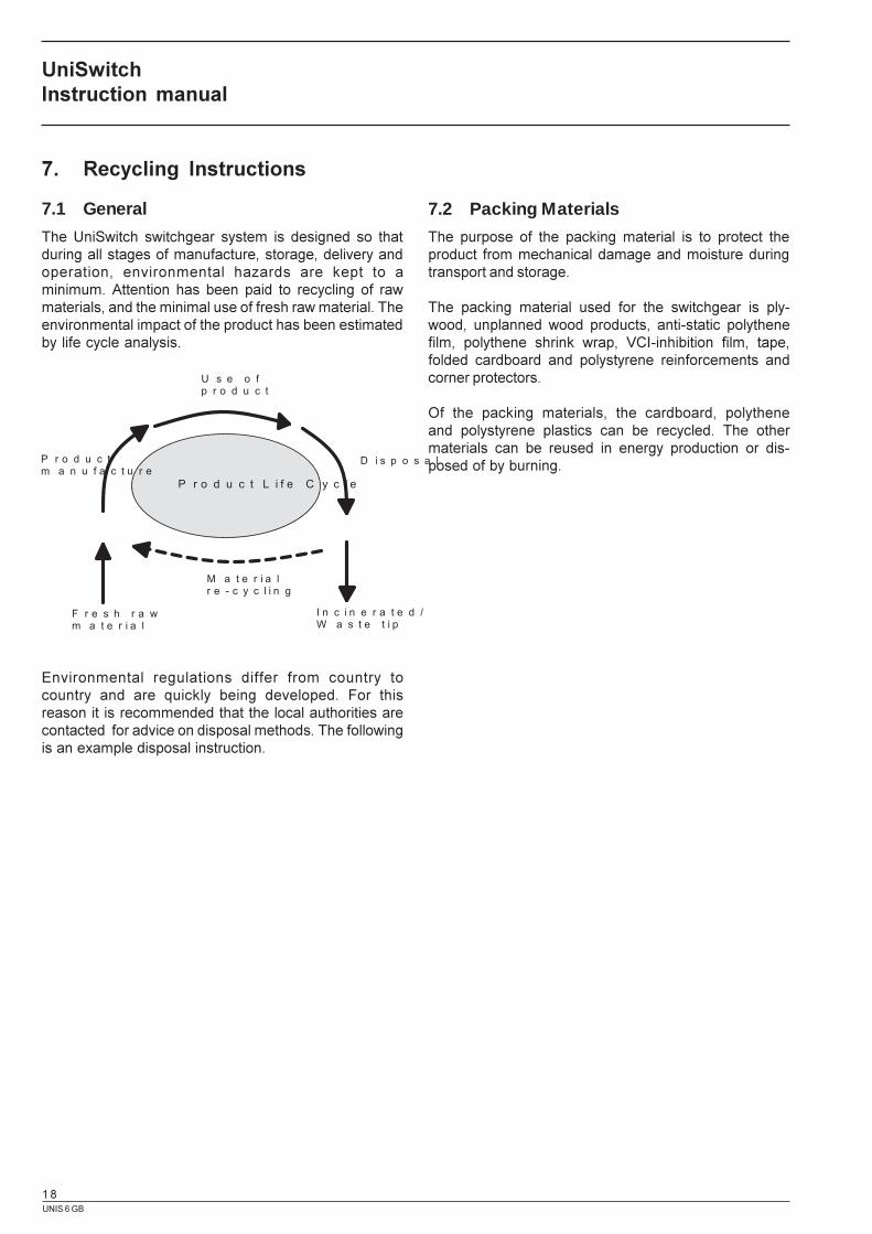
The UniSwitch switchgear system is designed so thatduring all stages of manufacture, storage, delivery andoperation, environmental hazards are kept to aminimum. Attention has been paid to recycling of rawmaterials, and the minimal use of fresh raw material. Theenvironmental impact of the product has been estimatedby life cycle analysis.
7.2 Packing Materials
The purpose of the packing material is to protect theproduct from mechanical damage and moisture duringtransport and storage.
The packing material used for the switchgear is ply-wood, unplanned wood products, anti-static polythenefilm, polythene shrink wrap, VCI-inhibition film, tape,folded cardboard and polystyrene reinforcements andcorner protectors.
Of the packing materials, the cardboard, polytheneand polystyrene plastics can be recycled. The othermaterials can be reused in energy production or dis-posed of by burning.
Environmental regulations differ from country tocountry and are quickly being developed. For thisreason it is recommended that the local authorities arecontacted for advice on disposal methods. The followingis an example disposal instruction.
UniSwitchInstruction manual
P r o d u c t L i f e C y c l e
F r e s h r a wm a t e r i a l
P r o d u c tm a n u f a c t u r e
U s e o f p r o d u c t
D i s p o s a l
I n c i n e r a t e d /W a s t e t i p
M a t e r i a lr e - c y c l i n g
UNIS 6 GB
19
7.3 Materials used in production
A switchgear cubicle that is to be removed from use canbest be disposed of by dismantling the parts by hand.The following materials have been used in the manufac-ture of the cubicles.
� Steel� Stainless steel� Copper� Bronze� Aluminium� Epoxy� EPDM-rubber� Various plastics� SF
6 - gas
The switchgear metal, plastic and EPDM-rubber partscan be recycled. The epoxy insulated instrument trans-formers and sensors can be crushed so that the copperparts inside can be reclaimed.
SFG switch-disconnector includes e.g. copper and SF6 �
gas, which are valuable materials for recycling. The re-cycling/disposal can be subcontracted to ABB or to aspecialist company.
Further information:
http://www.sf6.abb.com
IEC technical report 1634 (1995): �High-voltage switchgearand controlgear � Use and handling of sulphur hexafluoride(SF
6) in high-voltage switchgear and controlgear�, Clause
6.5: �Treatment at the end of life SF6 � filled equipment�.
UniSwitchInstruction manual

UNIS 6 GB
20
Information given in this publication isgenerally applicable to equipment des-cribed. Changes may be made in futurewithout notice.
Mul
tipri
nt, V
aasa
, 200
0U
NIS
6 G
B 2
000-0
1
Apparatus and Switchgear Business UnitP.O.Box 613, FIN-65101 Vaasa, FinlandTel: +358 10 22 4000Fax: +358 10 22 41748