unipower’s sgh9233-r1u - file.yizimg.comfile.yizimg.com/386444/2012061310093684.pdf ·...
TRANSCRIPT
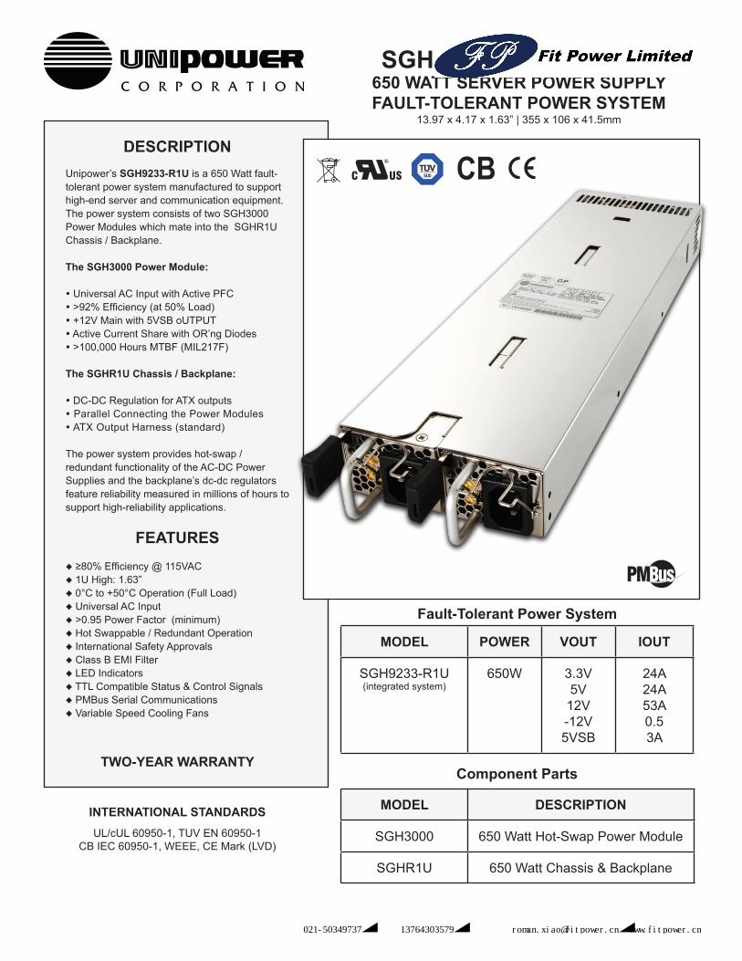
DESCRIPTIONUnipower’s SGH9233-R1U is a 650 Watt fault-tolerant power system manufactured to support high-end server and communication equipment. The power system consists of two SGH3000 Power Modules which mate into the SGHR1U Chassis / Backplane.
The SGH3000 Power Module:
Universal AC Input with Active PFC >92% Efficiency (at 50% Load) +12V Main with 5VSB oUTPUT Active Current Share with OR’ng Diodes >100,000 Hours MTBF (MIL217F)
The SGHR1U Chassis / Backplane:
DC-DC Regulation for ATX outputs Parallel Connecting the Power Modules ATX Output Harness (standard)
The power system provides hot-swap / redundant functionality of the AC-DC Power Supplies and the backplane’s dc-dc regulators feature reliability measured in millions of hours to support high-reliability applications.
FEATURES♦ ≥80% Efficiency @ 115VAC♦ 1U High: 1.63”♦ 0°C to +50°C Operation (Full Load)♦ Universal AC Input♦ >0.95 Power Factor (minimum)♦ Hot Swappable / Redundant Operation♦ International Safety Approvals♦ Class B EMI Filter♦ LED Indicators♦ TTL Compatible Status & Control Signals♦ PMBus Serial Communications♦ Variable Speed Cooling Fans
TWO-YEAR WARRANTY
INTERNATIONAL STANDARDSUL/cUL 60950-1, TUV EN 60950-1
CB IEC 60950-1, WEEE, CE Mark (LVD)
SGH9233-R1U MODULE650 WATT SERVER POWER SUPPLYFAULT-TOLERANT POWER SYSTEM
13.97 x 4.17 x 1.63” | 355 x 106 x 41.5mm
MODEL POWER VOUT IOUT
SGH9233-R1U(integrated system)
650W 3.3V5V
12V-12V5VSB
24A24A53A0.53A
Fault-Tolerant Power System
MODEL DESCRIPTION
SGH3000 650 Watt Hot-Swap Power Module
SGHR1U 650 Watt Chassis & Backplane
Component Parts
中国区总代理:上海佳舍珀电子科技有限公司 电话:021-50349737︱手机:13764303579︱电子邮件:[email protected]︱www.fitpower.cn
INPUTVoltage Range ............................................................................90-264 VACPower Factor ........................................................................................ >0.95Total Harmonic Distortion, Max .................................................................. 5%Frequency ..........................................................................................47-63HzInrush Current Limiting, Max ....................... 35 / 70A Peak @ 115 / 230 VACEMI Filter, Conducted ........................................... FCC20780 pt 15J Curve B
EN55022 Curve BFast Transients ..........................................................................EN61000-4-4Surges .......................................................................................EN61000-4-5Remote Sense Compensation ...........................................................>250mVInput Protection ................................................................. Internal Fuse, 15A
OUTPUTCurrent & Voltage ...................................................12V @ 54A, 5VSB @ 3A Output Power .........................................................................................650WRipple / Noise, max ...............................................12V = 120mV | 5V = 60mVLine Regulation.................................................................................Max ±1%Load Regulation, .............................................................................Max ±5%Transient Load / Slew Rate ................................................................. 0.5/AµsHoldup Time .................................................................. 17msec @ 70% loadOvervoltage Protection (12V Only) ............................... 14.5V Max (Latch Off)Current Limit ..................................................................... >130% (Latch Off)Efficiency ...............................................................87% Minimum at Full Load
SAFETY STANDARDS ....... UL60950-1, CSA22.2 No. 60950-1, EN60950-1
PMBus Version Compliance .................................................................. 1.1
STATUS INDICATORSNormal(AC OK) .................................................................................... GreenStandby (Only +5VSB output) .................................. (AC OK) Blinking GreenPower Fail .................................................................................................RedFan Fail ....................................................................................... Blinking RedAudible Buzzer ........................................................ Fan / Power / AC Failure
ALARM SIGNALS (open drain, TTL compatible)PSON .................................................................Remote ON Off (LOW=ON)PSKILL ............................................................................ Actives PSU (Short)PDBALERT ......................................................Run Fan at Max Spped (LOW)PDB FAULT ...................................................System Fault Shutdown (HIGH)PWOK .............................................................................Power Good (HIGH)PS Present ............................................... Indicates Power Module is present
ENVIRONMENTALOperating Temp. Range ..........................................0°C to +50°C (Full Load)Output Current Derating ................................................ 3%/°C, 50°C to 60°CStorage Temp. Range ............................................................ -40°C to + 70°CHumidity.............................................................0% to 95%, Non-CondensingESD ............................................ Bellcore GR-1089-Core and EN61000-4-2MTBF, 25°C (MIL217F) ............................................................100,000 HoursCooling .................................................................. Integral Ball Bearing Fans
PHYSICAL SPECIFICATIONSCase Material ......................................................................................... SteelCase Dimensions, Inches (mm) .................... 11.81”(L) x 1.99”(W) x 1.57”(H)
(300 x 50.5 x 40mm)Weight .................................................................................. 2.4 lbs. (1.1 kg.)
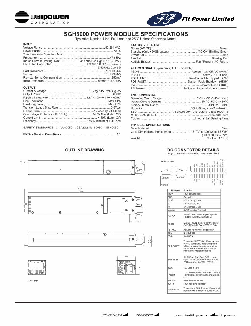
SGH3000 POWER MODULE SPECIFICATIONSTypical at Nominal Line, Full Load and 25°C Unless Otherwise Noted.
Description:
Product Specification
ETASIS Electronics Corporation
Model No.: EFRP-G657
ERP1U Redundant Power Module Document No.:
File Name: EFRP-G657_rev03.pdf Page : 9
9
Table 14 – Output Pin Assignment Pin Name Function System/Backplane Connection
+12V +12V power output TO SYSTEM 12V BUS GND Grounding GND 5VSB +5V standby power TO SYSTEM 5VSB BUS A0 I2C Address(LSB) A1 I2C Address(MSB)
B0 = 0/0 ; B2 = 1/0 ; B4 = 0/1 ; B6 = 1/1
Vsense 5VSB negative feedback Grounded at backplane
PW_OK Power Good Output. Signal is pulled HIGH to indicate all outputs ok. TO SYSTEM Power Good
PSON Module PSON. Remote control power On/Off (Pulled LOW = POWER ON)
PS_KILL Activate PSU by hot-plug activity Grounded at backplane SCL I2C CLOCK TO SYSTEM I2C BUS SDA I2C DATA TO SYSTEM I2C BUS
PDB-ALERT
To receive ALERT signal from system or PSU backplane, If signal is pulled LOW, the power internal fan shall be forced to run at maximum speed to improve thermal performance
This signal pin can be controlled by system, or floating via backplane.
SMB-ALERT If PSU FAIL,FAN FAIL,OCP occurs, signal will be pulled from High to Low , PSU normal =High(TTL LEVEL)
To system related bus
12LS 12V Load Share Connect pin to pin at backplane for each power module
Present This pin is grounded with a 47R resistor. To indicate a power has been plugged in.
floating via backplane.
12VRS+ +12V Remote sense TO SYSTEM 12V BUS
Description:
Product Specification
ETASIS Electronics Corporation
Model No.: EFRP-G657
ERP1U Redundant Power Module Document No.:
File Name: EFRP-G657_rev03.pdf Page : 10
10
12VRS- +12V negative feedback Grounded at backplane
PDB-FAULT To receive a FAULT signal. Power shall be shutdown if this pin is pulled HIGH. floating via backplane.
7.3 Mating Connector
Molex 45984 Series
8.LED Indicators There will be a LED on each power module to indicate power status
Table 15 – LED Color and Power Status Power Supply Status Color
Normal(AC OK) Green Standby (Only +5VSB output) (AC OK) Blinking Green
Power Fail Red Fan Fail Blinking Red AC Loss Red
9. Buzzer Status Alarm reset is used to clear power fail status by shorting circuit activities. Buzzer shall alarm if signal goes low.
Table 16– Buzzer Status Power Supply Status Buzzer Status
Normal (AC OK) Mute Power Fail Alarm Fan Fail Alarm AC Loss Alarm
OUTLINE DRAWING DC CONNECTOR DETAILSEdge Connector mates with Molex 45984-4161
5VSB
5VSB A2
- - - -
AC O
K
PDB
ALER
T A0
PRES
ENT
PDB
FAUL
T
5VSB
5VSB
A1 PW O
K
PS O
N
PS K
ILL
SCL
SDA
SMB
ALER
T
12V
ISHA
RE
- SEN
SE (1
2V)
+SEN
SE (1
2V)
+12V
GROUND
+12V
GROUND
TOP SIDE
BOTTOM SIDE
Unit: mm
中国区总代理:上海佳舍珀电子科技有限公司 电话:021-50349737︱手机:13764303579︱电子邮件:[email protected]︱www.fitpower.cn
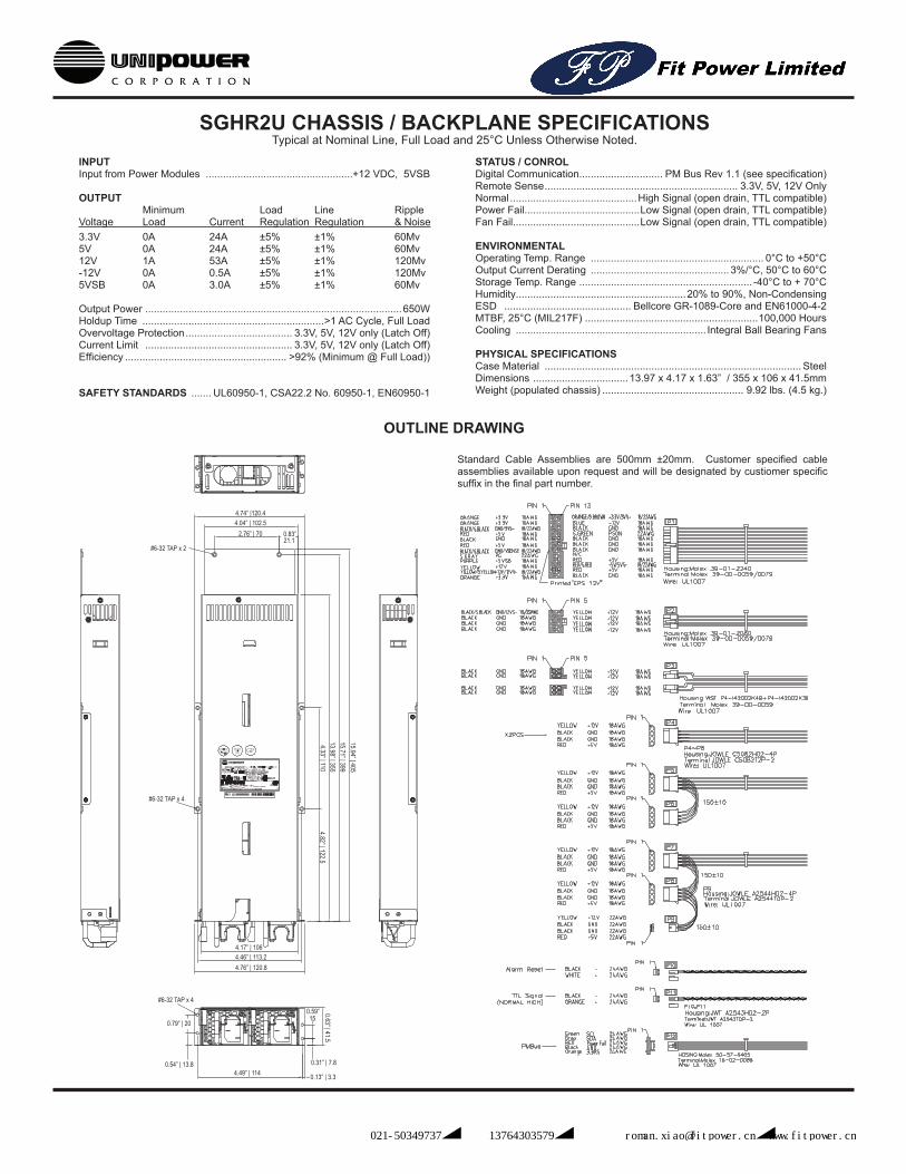
SGHR2U CHASSIS / BACKPLANE SPECIFICATIONSTypical at Nominal Line, Full Load and 25°C Unless Otherwise Noted.
INPUTInput from Power Modules ...................................................+12 VDC, 5VSB
OUTPUT Minimum Load Line RippleVoltage Load Current Regulation Regulation & Noise3.3V 0A 24A ±5% ±1% 60Mv5V 0A 24A ±5% ±1% 60Mv 12V 1A 53A ±5% ±1% 120Mv-12V 0A 0.5A ±5% ±1% 120Mv5VSB 0A 3.0A ±5% ±1% 60Mv
Output Power .........................................................................................650WHoldup Time ...............................................................>1 AC Cycle, Full LoadOvervoltage Protection ..................................... 3.3V, 5V, 12V only (Latch Off)Current Limit ................................................... 3.3V, 5V, 12V only (Latch Off)Efficiency ........................................................ >92% (Minimum @ Full Load))
SAFETY STANDARDS ....... UL60950-1, CSA22.2 No. 60950-1, EN60950-1
STATUS / CONROLDigital Communication............................. PM Bus Rev 1.1 (see specification)Remote Sense ................................................................... 3.3V, 5V, 12V OnlyNormal ............................................High Signal (open drain, TTL compatible)Power Fail........................................Low Signal (open drain, TTL compatible)Fan Fail............................................Low Signal (open drain, TTL compatible)
ENVIRONMENTALOperating Temp. Range ............................................................ 0°C to +50°COutput Current Derating ................................................ 3%/°C, 50°C to 60°CStorage Temp. Range ............................................................ -40°C to + 70°CHumidity...........................................................20% to 90%, Non-CondensingESD ............................................ Bellcore GR-1089-Core and EN61000-4-2MTBF, 25°C (MIL217F) ............................................................100,000 HoursCooling .................................................................. Integral Ball Bearing Fans
PHYSICAL SPECIFICATIONSCase Material ......................................................................................... SteelDimensions .................................13.97 x 4.17 x 1.63” / 355 x 106 x 41.5mmWeight (populated chassis) ................................................. 9.92 lbs. (4.5 kg.)
OUTLINE DRAWING
Standard Cable Assemblies are 500mm ±20mm. Customer specified cable assemblies available upon request and will be designated by custiomer specific suffix in the final part number.
中国区总代理:上海佳舍珀电子科技有限公司 电话:021-50349737︱手机:13764303579︱电子邮件:[email protected]︱www.fitpower.cn
INDICATORS
PMBus SPECIFICATIONS
80 PLUS Verification and Testing Report
TYPICAL EFFICIENCY (50% Load):AVERAGE EFFICIENCY :80 PLUS COMPLIANT: YES
UnitsVoltsAmpsHzWatts
Note: All measurements were taken with input voltage at 230 V nominal and 60 Hz. Input AC Current Waveform (ITHD = 8.1%, 100% Load)
IRMS PFA 5Vsb
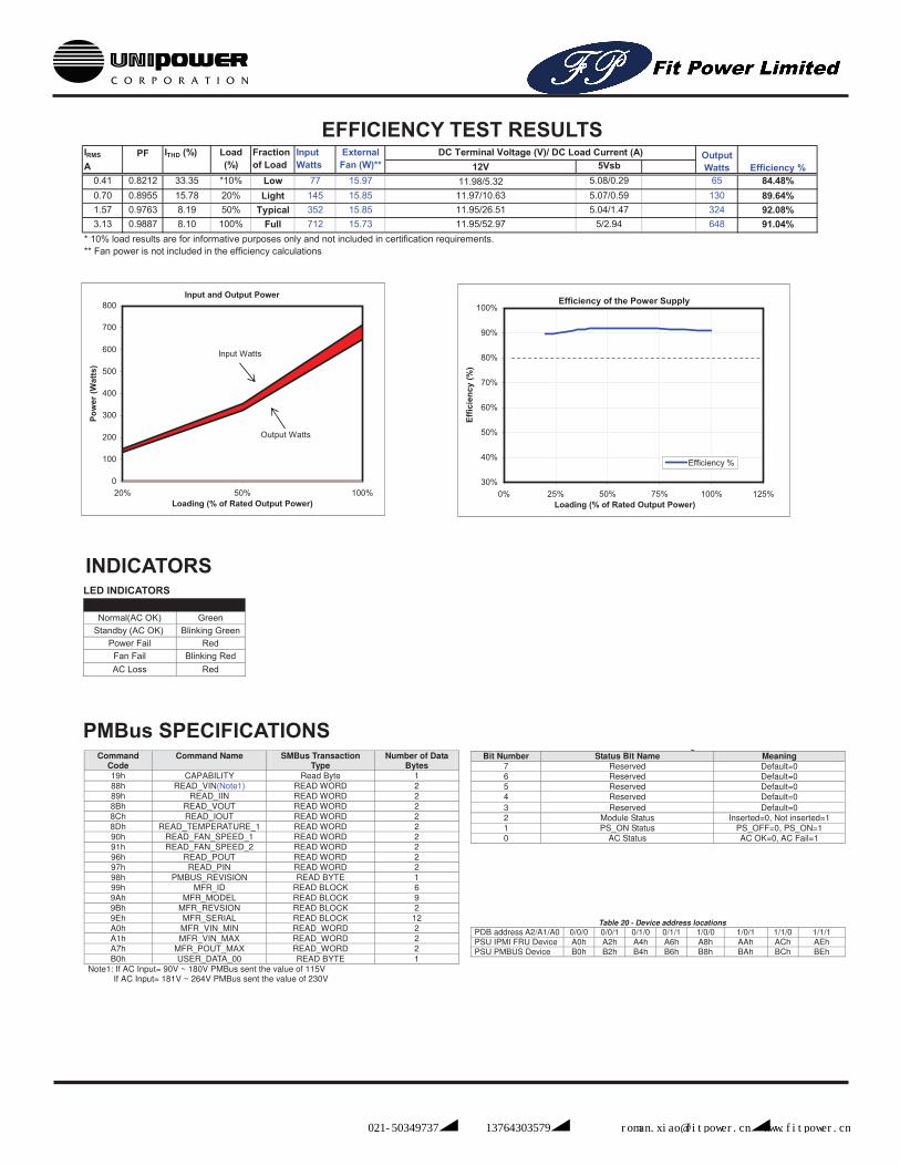
0.41 0.8212 33.35 *10% Low 77 15.97 5.08/0.29 65 84.48%0.70 0.8955 15.78 20% Light 145 15.85 5.07/0.59 130 89.64%1.57 0.9763 8.19 50% Typical 352 15.85 5.04/1.47 324 92.08%3.13 0.9887 8.10 100% Full 712 15.73 5/2.94 648 91.04%
.
11-5.547-63650
Rated SpecificationsInput VoltageInput Current
Input Frequency
Efficiency %
Test Date
External Fan (W)** 12V
DC Terminal Voltage (V)/ DC Load Current (A)
2/10/2010
Output Watts
Rated Output Power
Value100-240
. ..
Load (%)
1U ERP1UType
ITHD (%) Input Watts
Fraction of Load
* 10% load results are for informative purposes only and not included in certification requirements.** Fan power is not included in the efficiency calculations
11.98/5.3211.97/10.6311.95/26.5111.95/52.97
Year
Manufacturer
N/A2010
Model Number EFRP-G657Serial Number
92.08%90.92%
ETASISEcos ID # SO-131
Input and Output Power
Input Watts
Output Watts
0
100
200
300
400
500
600
700
800
20% 50% 100%Loading (% of Rated Output Power)
Pow
er (W
atts
)
Efficiency of the Power Supply
30%
40%
50%
60%
70%
80%
90%
100%
0% 25% 50% 75% 100% 125%Loading (% of Rated Output Power)
Effic
ienc
y (%
)Efficiency %
Input Current and Voltage Waveforms
-400
-300
-200
-100
0
100
200
300
400
0 0.003 0.006 0.009 0.012 0.015
Time (s)
Vol
tage
(V)
-6
-4
-2
0
2
4
6
Cur
rent
(A)
Voltage Current
These tests were conducted by a third party independent testing firm on behalf of the 80 PLUS® Program. 80 PLUS is a certification program to promote highly-efficient power supplies (greater than 80% efficiency in the active mode) in technology applications. http://www.80plus.org/
EFFICIENCY TEST RESULTS
LED INDICATORS
4 Reserved Default=0 3 Reserved Default=0 2 Module Status Inserted=0, Not inserted=1 1 PS_ON Status PS_OFF=0, PS_ON=1 0 AC Status AC OK=0, AC Fail=1
Table 19 - Device address locations
PDB adderss A0/A1 0/0 0/1 1/0 1/1 PSU PMBUS Device B0h B2h B4h B6h
Note1: If AC Input= 90V ~ 180V PMBus sent the value of 115V If AC Input= 181V ~ 264V PMBus sent the value of 230V
Status BYTE Message Contents Command code = B0h (Command name = USER_DATA_00)
Status BYTE Message Contents Bit Number Status Bit Name Meaning
7 Reserved Default=0 6 Reserved Default=0 5 Reserved Default=0
Command Code
Command Name SMBus Transaction Type
Number of Data Bytes
19h CAPABILITY Read Byte 1 1Ah QUERY Read Byte 1 88h READ_VIN(Note1) READ WORD 2 89h READ_IIN READ WORD 2 8Bh READ_VOUT READ WORD 2 8Ch READ_IOUT READ WORD 2 8Dh READ_TEMPERATURE_1 READ WORD 2 90h READ_FAN_SPEED_1 READ WORD 2 91h READ_FAN_SPEED_2 READ WORD 2 96h READ_POUT READ WORD 2 97h READ_PIN READ WORD 2 98h PMBUS_REVISION READ BYTE 1 99h MFR_ID R/W Block Variable 9Ah MFR_MODEL R/W Block Variable 9Bh MFR_REVSION R/W Block Variable 9Eh MFR_SERIAL R/W Block Variable A0h MFR_VIN_MIN READ_WORD 2 A1h MFR_VIN_MAX READ_WORD 2 A7h MFR_POUT_MAX READ_WORD 2 B0h USER_DATA_00 READ BYTE 1
Power Supply Status Color Normal(AC OK) Green
Standby (AC OK) Blinking Green Power Fail Red Fan Fail Blinking Red AC Loss Red
Power Supply Status Buzzer Status Normal (AC OK) Mute
Power Fail Alarm Fan Fail Alarm AC Loss Alarm
Description:
Product Specification
ETASIS Electronics Corporation
Model No.: EFRP-G657
ERP1U Redundant Power Module Document No.:
File Name: EFRP-G657_rev12.pdf Page : 11
11
9.PMBus Command Codes Table 16 –PMBus Command Codes
Note1: If AC Input= 90V ~ 180V PMBus sent the value of 115V If AC Input= 181V ~ 264V PMBus sent the value of 230V
Table 17–MFR Meanings Command
Code Command Name Meaning
99h MFR_ID ETASIS 9Ah MFR_MODEL EFRP-G657 9Bh MFR_REVSION A0 ~ Z9 9Eh MFR_SERIAL Serial Number A0h MFR_VIN_MIN 100VAC A1h MFR_VIN_MAX 240VAC A7h MFR_POUT_MAX 650W
Status BYTE Message Contents Command code = B0h (Command name = USER_DATA_00)
Table 19 –Status BYTE Message Contents Bit Number Status Bit Name Meaning
7 Reserved Default=0 6 Reserved Default=0 5 Reserved Default=0 4 Reserved Default=0
Command Code
Command Name SMBus Transaction Type
Number of Data Bytes
19h CAPABILITY Read Byte 1 88h READ_VIN(Note1) READ WORD 2 89h READ_IIN READ WORD 2 8Bh READ_VOUT READ WORD 2 8Ch READ_IOUT READ WORD 2 8Dh READ_TEMPERATURE_1 READ WORD 2 90h READ_FAN_SPEED_1 READ WORD 2 91h READ_FAN_SPEED_2 READ WORD 2 96h READ_POUT READ WORD 2 97h READ_PIN READ WORD 2 98h PMBUS_REVISION READ BYTE 1 99h MFR_ID READ BLOCK 6 9Ah MFR_MODEL READ BLOCK 9 9Bh MFR_REVSION READ BLOCK 2 9Eh MFR_SERIAL READ BLOCK 12 A0h MFR_VIN_MIN READ_WORD 2 A1h MFR_VIN_MAX READ_WORD 2 A7h MFR_POUT_MAX READ_WORD 2 B0h USER_DATA_00 READ BYTE 1
Description:
Product Specification
ETASIS Electronics Corporation
Model No.: EFRP-G657
ERP1U Redundant Power Module Document No.:
File Name: EFRP-G657_rev12.pdf Page : 12
12
3 Reserved Default=0 2 Module Status Inserted=0, Not inserted=1 1 PS_ON Status PS_OFF=0, PS_ON=1 0 AC Status AC OK=0, AC Fail=1
Table 20 - Device address locations
PDB address A2/A1/A0 0/0/0 0/0/1 0/1/0 0/1/1 1/0/0 1/0/1 1/1/0 1/1/1 PSU IPMI FRU Device A0h A2h A4h A6h A8h AAh ACh AEh PSU PMBUS Device B0h B2h B4h B6h B8h BAh BCh BEh
10.Mechanical Overview Dimension: 50.5mm(W) x 40mm(H) x 300mm(D) Weight: 1.1 Kg
中国区总代理:上海佳舍珀电子科技有限公司 电话:021-50349737︱手机:13764303579︱电子邮件:[email protected]︱www.fitpower.cn