uninterruptible power supply 7011a series · pdf filerevision 6.5: jan. 24, 2003 aln-h0379...
TRANSCRIPT

Revision 6.5: Jan. 24, 2003ALN-H0379
MITSUBISHI
UNINTERRUPTIBLE POWER SUPPLY7011A SERIES UPS
SINGLE PHASE PRODUCT6kVA8kVA10kVA12kVA
OWNERS / TECHNICAL MANUALOWNERS / TECHNICAL MANUALOWNERS / TECHNICAL MANUALOWNERS / TECHNICAL MANUAL
MITSUBISHI ELECTRIC 7011A SERIES UPS
MITSUBISHIELECTRIC
7011A SERIES UPSOWNERS / TECHNICAL MANUAL
Page Number:i
Preface
MITSUBISHI ELECTRIC 7011A SERIES UPS
MITSUBISHIELECTRIC
7011A SERIES UPSOWNERS / TECHNICAL MANUAL
Page Number:ii
TABLE OF CONTENTS
LIST OF TABLES ................................................................................................. iiiLIST OF FIGURES ............................................................................................... ivHOW TO USE THIS MANUAL ............................................................................. vSAFETY PRECAUTIONS HOW TO USE THIS MANUAL ................................... vi
1.0 INTRODUCTION ........................................................................................... 1-11.1 GENERAL....................................................................................................... 1-31.2 DEFINITIONS ................................................................................................ 1-41.3 OVERVIEW ................................................................................................... 1-51.4 SPECIFICATIONS ......................................................................................... 1-12
2.0 OPERATOR CONTROLS AND INDICATORS ............................................ 2-12.1 STATUS INDICATORS .................................................................................. 2-22.2 LCD DISPLAY ............................................................................................... 2-42.3 RS232C CONNECTOR (External communication connector)....................... 2-72.4 D-SUB 25 PIN CONNECTOR ....................................................................... 2-82.5 EXTERNAL SIGNAL TERMINAL BLOCK ..................................................... 2-9
3.0 INSTALLATION AND OPERATION ............................................................. 3-13.1 TRANSPORTATION AND INSTALLATION ................................................. 3-13.2 INSTALLATION PROCEDURE .................................................................... 3-13.3 PROCEDURE FOR CABLE CONNECTION................................................. 3-23.4 INSTALLATION PROCEDURE FOR BATTERY .......................................... 3-93.5 OPERATING PROCEDURES ...................................................................... 3-123.6 MAINTENANCE BYPASS SET-UP PROCEDURES ................................... 3-143.7 EXTERNAL BATTERY SET-UP PROCEDURES ........................................ 3-15
4.0 RESPONSE TO UPS FAILURE .................................................................... 4-1
5.0 PARTS REPLACEMENT .............................................................................. 5-1
6.0 FAULT CODES ............................................................................................. 6-1
7.0 WARRANTY & OUT OF WARRANTY SERVICE ......................................... 7-1
MITSUBISHI ELECTRIC 7011A SERIES UPS
MITSUBISHIELECTRIC
7011A SERIES UPSOWNERS / TECHNICAL MANUAL
Page Number:iii
List of Tables
Table 1.1 Power Specifications..................................................................... 1-12Table 1.2 UPS Module Information............................................................... 1-12Table 1.3 Rating of Conductor and Fuses .................................................... 1-12Table 1.4 Detail of Specifications.................................................................. 1-13Table 2.1 D-Sub 25 Pin connector ................................................................ 2-9Table 3.1 List of UPS Weights (lb.) ............................................................... 3-1Table 3.2 Recommended Cable Size and Torque Requirements................ 3-3Table 3.3 Crimp Type Compression Lug ...................................................... 3-3Table 3.4 Type and Number of Battery......................................................... 3-9Table 6.1 Failure Code List ........................................................................... 6-2
MITSUBISHI ELECTRIC 7011A SERIES UPS
MITSUBISHIELECTRIC
7011A SERIES UPSOWNERS / TECHNICAL MANUAL
Page Number:iv
List of Figures
Figure 1.1 Single Line Diagram-Normal Operation........................................ 1-5
Figure 1.2 Single Line Diagram-Bypass Operation........................................ 1-6
Figure 1.3 Single Line Diagram-Battery Operation ........................................ 1-7
Figure 1.4 Single Line Diagram - UPS on Maintenance Bypass Operation. . 1-7
Figure 1.5 UPS Parts Location (6kVA)........................................................... 1-8
Figure 1.6 UPS Parts Location (8,10,12kVA)................................................. 1-9
Figure 1.7 UPS Parts Location (Rear view) ................................................... 1-10
Figure 1.8 External I/F PCB RYER-A ............................................................ 1-10
Figure 2.1 Operation / Display Panel ............................................................ 2-1
Figure 2.2 LCD Display During Normal Operation ........................................ 2-2
Figure 2.3 Tree Diagram of LCD display (Top Page) ................................... 2-4
Figure 2.4 Tree Diagram of LCD display (Normal Mode) ............................. 2-5
Figure 2.5 Tree Diagram of LCD display (User Setup Mode) ....................... 2-6
Figure 2.6 Tree Diagram of LCD display (Start Mode) ................................. 2-6
Figure 2.7 Tree Diagram of LCD display (Stop Mode) .................................. 2-6
Figure 2.8 Tree Diagram of LCD display (Stop Mode) .................................. 2-7
Figure 2.9 RS-232C Connectors ................................................................... 2-8
Figure 2.10 D-sub 25 Pin Connector ............................................................... 2-9
Figure 2.11 External Signal Terminal Block (NEC Class2).............................. 2-10
Figure 2.12 Control Wiring for External Contacts ............................................ 2-11
Figure 2.13 Remote “Startup” Contact Connections........................................ 2-12
Figure 3.1 Handling ....................................................................................... 3-1
Figure 3.2 Clearance for Ventilation and Maintenance ................................. 3-2
Figure 3.3 UPS Terminal Designation............................................................ 3-4
Figure 3.4 Terminal Block............................................................................... 3-5
Figure 3.5 Input / Output Power Terminals (6kVA) (Rear View).................... 3-5
Figure 3.6 Input / Output Power Terminals (8,10,12kVA) (Rear View).......... 3-6
Figure 3.7 Field Wire Connection (208V-120 V WYE, 2 Phase 3 Wire)........ 3-7
Figure 3.8 Field Wire Connection (240V-120 V, 1 Phase 3 Wire) ................. 3-9
Figure 3.9 Battery Connection when shipped ................................................ 3-12

MITSUBISHI ELECTRIC 7011A SERIES UPS
MITSUBISHIELECTRIC
7011A SERIES UPSOWNERS / TECHNICAL MANUAL
Page Number:v
HOW TO USE THIS MANUALHOW TO USE THIS MANUALHOW TO USE THIS MANUALHOW TO USE THIS MANUAL
This manual is designed for ease of use, giving the user easy and quick reference to information.
This manual uses notice icons to draw attention to the user important information regarding the safe
operation and installation of the UPS. The notice icons used in this manual are explained below, and
should be taken into account and adhered to whenever they appear in the text of this manual.
WARNING: A warning notice icon conveys information provided to protect the user
and service personnel against hazards and/or possible equipment damage.
CAUTION: A caution notice icon conveys information provided to protect the user and
service personnel against possible equipment damage.
NOTE: A Note notice icon indicates when the user should make a reference of
information regarding the UPS operation, load status and display status.
Such information is essential if Mitsubishi field service group assistance and
correspondence is required.
Safety Recommendations: If any problems are encountered while following this manual, Mitsubishi
field service group assistance and correspondence is recommended.

MITSUBISHI ELECTRIC 7011A SERIES UPS
MITSUBISHIELECTRIC
7011A SERIES UPSOWNERS / TECHNICAL MANUAL
Page Number:vi
SAFETY PRECAUTIONSSAFETY PRECAUTIONSSAFETY PRECAUTIONSSAFETY PRECAUTIONS
The safety precautions are categorized as DANGER and CAUTION in this instruction manual.
DANGER: A dangerous situation may occur if improperly handled, leading to severe or fatal
injuries.
CAUTION: A dangerous situation may occur if improperly handled, leading to minor serious
injuries.
Note that some items described as CAUTION may lead to severe results depending on the
situation. Nonetheless, important information outlined in this section must be observed at all times.
DANGER• Do not dispose of the batteries in a fire as they may explode.• Do not open or break the batteries. Released electrolyte is toxic and harmful to the
eyes and skin.• A battery can present a risk of electrical shock and high short circuit current.
Observe the following minimum Safety Precautions when working on the batteries.1) Verify that the UPS is off and that the input power plug or wires are disconnected.
2) Remove watches, rings or other metal objects.
3) Use tools with insulated handles to prevent inadvertent shorts.
4) Wear rubber gloves and boots.
5) Do not lay tools or metal parts on top of the batteries.
6) Determine if the battery is inadvertently grounded. If so, remove source of ground.
Contact with any part of a grounded battery can result in electrical shock. The likelihood
of such shock will be reduced if grounds are removed during installation and
maintenance.

MITSUBISHI ELECTRIC 7011A SERIES UPS
MITSUBISHIELECTRIC
7011A SERIES UPSOWNERS / TECHNICAL MANUAL
Page Number:vii
CAUTION
PRECAUTIONS FOR INSTALLATIONPRECAUTIONS FOR INSTALLATIONPRECAUTIONS FOR INSTALLATIONPRECAUTIONS FOR INSTALLATION• Do not block the intake/exhaust ports. Install the UPS at least 4” (10cm) away from
walls, etc.-If the intake/exhaust ports are blocked, the internal temperature of the UPS will rise and
could lead to fires from battery electrolyte leakage, fire ignition or part deterioration.
• Follow the UPS instruction manual carefully when installing the unit.-Improper installation could lead to injury such as the UPS falling over, etc.
PRECAUTIONS FOR WIRINGPRECAUTIONS FOR WIRINGPRECAUTIONS FOR WIRINGPRECAUTIONS FOR WIRING• The power supply for this unit must be single phase rated in accordance with the
equipment data plate. It must be suitably grounded.-Failure to ground the unit could lead to electrical shocks.
PRECAUTIONSPRECAUTIONSPRECAUTIONSPRECAUTIONS FOR USEFOR USEFOR USEFOR USE• If a unit fault, abnormal odor or noise occurs, turn off the UPS input switch.
-Failure to do so could lead to fires.
• Do not insert blunt objects or fingers, etc., in the fan.-Failure to observe this could lead to injuries.
• Do not insert blunt objects or fingers, etc., into the unit's input/output section.-Failure to observe this could lead to electrical shocks.
• Ventilate the UPS surroundings.-Failure to do so could lead to container rupture or to explosions from the gas generated
from the battery system.
• Prohibit smoking and the use of fire around the unit.-Failure to do so could lead to injuries, damage or fires from explosions.
• Do not place containers that have water or any liquids on the UPS.-If the container tips over and the water or liquids spills, this could lead to electrical shocks
and to fires in the UPS.
• Do not sit on, step on or lean on the UPS.-Failure to observe this could lead to injuries if the UPS tips over.

MITSUBISHI ELECTRIC 7011A SERIES UPS
MITSUBISHIELECTRIC
7011A SERIES UPSOWNERS / TECHNICAL MANUAL
Page Number:viii
CAUTION
PRECAUTIONS FOR MAINTENANCE AND INSPECTIONPRECAUTIONS FOR MAINTENANCE AND INSPECTIONPRECAUTIONS FOR MAINTENANCE AND INSPECTIONPRECAUTIONS FOR MAINTENANCE AND INSPECTION• The inside of the UPS must be inspected or repaired only by qualified personnel.
-Failure to observe this could lead to electrical shocks, injuries, burns, smoke generation orfires.
• Periodically replace the battery (every 5 years).-Batteries that have exceeded the replacement life could lead to fires from electrolyte leakage
or fire ignition.• Contact the dealer or service company for unit maintenance and repairs, and for the
replacement of defective parts.-Opening the cover could lead to electrical shocks or burns.
PRECAUTIONS FOR BATTERYPRECAUTIONS FOR BATTERYPRECAUTIONS FOR BATTERYPRECAUTIONS FOR BATTERY• If the battery ignites, do not use water to extinguish the fire. Instead, use a powder (ABC)
fire extinguisher.-Use of water could cause the fire to grow.
• Toxic diluted sulfuric acid in the battery.-If electrolyte leaks from the unit, avoid contact with the skin or clothes.If electrolyte makes contact with the skin or clothes, wash it off thoroughly with clean water.If electrolyte makes contact with the eyes, rinse immediately and thoroughly with clean water,and then see a doctor. The presence of sulfuric acid in the eyes could lead to blindness, andadherence to skin could lead to burns.
OTHER PRECAUTIONSOTHER PRECAUTIONSOTHER PRECAUTIONSOTHER PRECAUTIONS• Never use or store the unit in the following types of environment:
a) A location having a low or high temperature, or high humidity deviated from the ambientenvironment conditions described in the brochure or instruction manual.
b) A location submerged in water or where the unit could become wet from dripping water.c) At an altitude higher than 5000 feet (1500 meters).d) In direct sunlight.e) Where organic solvents (gasoline, paint thinner, etc.) are stored.f) A location that is dusty.g) A location containing combustible gas, corrosive gas, salt or oil mist.h) A location subject to vibration or impacts.i) A location near devices that generate sparks or near heating elements.

MITSUBISHI ELECTRIC 7011A SERIES UPS
MITSUBISHIELECTRIC
7011A SERIES UPSOWNERS / TECHNICAL MANUAL
Page Number:1-1
1.0 INTRODUCTION
The Mitsubishi Uninterruptible Power Supply (UPS) is designed to provide many years of reliablepower supply and protection from power failure, brown-outs, line noise, and voltage transients.To ensure optimum performance of the equipment, follow the manufacturer's instructionsaccordingly. This manual contains descriptions for the installation and operation procedures ofthe UPS. Please read this manual carefully and retain it for future reference.
This manual contains important instructions for the 7011A Series Uninterruptible Power SupplySystems that should be adhered to during installation, operation and maintenance of the UPSand batteries.
Lethal voltages exist within the equipment during operation.Observe all warning and cautions in this manual.Failure to comply may result in serious injury or death.Obtain a qualified service for this equipment as per instructions.
IMPORTANT SAFETY INSTRUCTIONSRETAIN THESE INSTRUCTIONS
WARNING 1

MITSUBISHI ELECTRIC 7011A SERIES UPS
MITSUBISHIELECTRIC
7011A SERIES UPSOWNERS / TECHNICAL MANUAL
Page Number:1-2
This UPS does not include an AC input circuit breaker (MCCB) to protect the bypass andmain input circuit. The AC input circuit breaker (MCCB) is to be field supplied andinstalled. Circuit breaker (MCCB) specifications are as follows:
Capacity(kVA)
AC inputVoltage (Vac)
AC input Rating(Aac)
RecommendedBreaker (A)
6 208 26.4 358 208 35.2 45
10 208 44.0 6012 208 52.8 70
AC output and DC input overcurrent protection and disconnection devices shall be fieldsupplied and installed.
WARNING 2

MITSUBISHI ELECTRIC 7011A SERIES UPS
MITSUBISHIELECTRIC
7011A SERIES UPSOWNERS / TECHNICAL MANUAL
Page Number:1-3
1.1 GENERAL
The Mitsubishi 7011A Series UPS is designed to provide continuous and clean electricalpower to a critical load. In the event of an input power failure, the UPS will supply power tothe critical load for the specified battery time.
If the input power is not restored promptly, backup power from the UPS battery permits theorderly shutdown of equipment supported by the UPS. The UPS is simple to start up,operate and maintain.
The 7011A Series UPS is available in four (4) kVA sizes: 6, 8, 10 and 12kVA. Specificationsfor each kVA model appear in Section 1.4. All models have batteries included in the UPSmodule cabinet. The principles of operation described herein are applicable to all models.
This manual provides an overview of the 7011A Series components and their functions. Theappearance and purpose of operator controls and indicators is described with procedures foroperation, start-up, shutdown and basic maintenance included.
MITSUBISHI ELECTRIC 7011A SERIES UPS
MITSUBISHIELECTRIC
7011A SERIES UPSOWNERS / TECHNICAL MANUAL
Page Number:1-4
1.2 DEFINITIONS
UNINTERRUPTIBLE POWER SUPPLY SYSTEM (UPS) - All components within the UPSModule Cabinet and associated batteries which function as a system to provide continuous,conditioned AC power to a load. This is sometimes referred to as the "System".
UPS MODULE CABINET - The metal enclosure which contains Converter & InverterModule, I/O Module, batteries, and operator controls required to provide specified AC powerto a load.
CONVERTER & INVERTER MODULE - The Converter / Charger and Inverter assemblywhich, under the direction of the I/O Module and operator controls, provide specified ACpower to a load.
I/O MODULE – Assembly which contains Static Transfer Switch, the internal bypass line,and the internal control system. With operator controls, gives directions required to theConverter & Inverter Module to provide specified AC power to a load.
CONVERTER / CHARGER - The UPS component which contain the equipment and controlsnecessary to convert input AC power to regulated DC power required for battery chargingand for supplying power to the Inverter.
INVERTER – The UPS component which contain the equipment and controls necessary toconvert DC power from the Converter / Charger, or the battery, to AC power required by thecritical load.
STATIC TRANSFER SWITCH - Device which connects critical load to the bypass line whenthe Inverter cannot supply continuous power.
MAINTENANCE BYPASS LINE - Line which conducts electricity directly from the input powersource to the critical load during maintenance or whenever the UPS is not completelyoperational.
AC INPUT POWER - Power provided by the electrical utility company, or auxiliary generator,which is connected to the UPS for supplying critical load and recharging the battery.
BATTERY - Rechargeable battery strings which supply DC power to the inverter to maintaincontinuous AC power to the load during AC input power failure conditions.

MITSUBISHI ELECTRIC 7011A SERIES UPS
MITSUBISHIELECTRIC
7011A SERIES UPSOWNERS / TECHNICAL MANUAL
Page Number:1-5
1.3 OVERVIEW
The UPS provides two power paths between the utility source and the critical load. Figure 1.1shows the path for normal operation, with the load powered from the inverter. Figure 1.2 showsthe path for bypass operation, with the load supplied through the static bypass line.
FIGURE 1.1 Single Line Diagram - Normal Operation. Load powered by inverter.
During normal operation, the path through the inverter is used to power the load.
Referring to Figure 1.1: Input AC power is converted to DC by the Converter. DC power isutilized to charge the UPS battery and to provide power to the Inverter. The Inverter converts theDC power to clean AC power to supply the critical load.
The conversion - inversion process eliminates any voltage transients or fluctuations existing in theinput power before it reaches the critical load.
* The Input circuit breaker(MCCB) for protection of the UPS and cablesare field supplied and field installed. (See WARNING 2 in section 1.0).
AC input
CB
User suppliedMCCB
UPS Cabinet
Static TransferSwitch
Power Flow
Not in Use
FB
CB2
CONVERTER INVERTER
Output
CB1 FI FO
BATTERY
52CS
MaintenanceBypass Switch

MITSUBISHI ELECTRIC 7011A SERIES UPS
MITSUBISHIELECTRIC
7011A SERIES UPSOWNERS / TECHNICAL MANUAL
Page Number:1-6
FIGURE 1.2 Single Line Diagram - Bypass Operation. Load fed through static bypass line.
Referring to Figure 1.2, the Internal Static Bypass line is a hard-wired line which supplies thecritical load with unconditioned input power. The purpose of this line is to route power to thecritical load while the UPS module is de-energized (converter and inverter), and during Start-upbefore the system is fully operational.
The internal control system determines the operation of the two paths, with the load poweredfrom the inverter being the normal operation.
Referring to Figure 1.3, if the input power is interrupted, the battery will immediately supply theDC power required by the Inverter to maintain continuous AC power to the load. A fully chargedbattery will provide power for the specified time at the rated load, or longer at reduced load.
When power is restored after a low battery shutdown, the Converter automatically restartsoperation, recharges the batteries and the Inverter is automatically restarted without operatorintervention. The load is assumed by the inverter automatically without operator intervention.
In the event of a power failure, the Converter will de-energize and the batteries will discharge intothe Inverter and maintain power to the critical load until a) the battery capacity expires and theinverter turns off, or b) input power is restored after which the converter will power the inverterand simultaneously recharge the batteries. Figure 1.3 illustrates the flow diagram during batteryoperation.
MaintenanceBypass Switch
FB
BATTERY
CB2
Static TransferSwitch
Power Flow
Not in Use
Output
CB1 FI FO
CONVERTER INVERTER
UPS Cabinet
52CS
AC input
CB
User suppliedMCCB
MITSUBISHI ELECTRIC 7011A SERIES UPS
MITSUBISHIELECTRIC
7011A SERIES UPSOWNERS / TECHNICAL MANUAL
Page Number:1-7
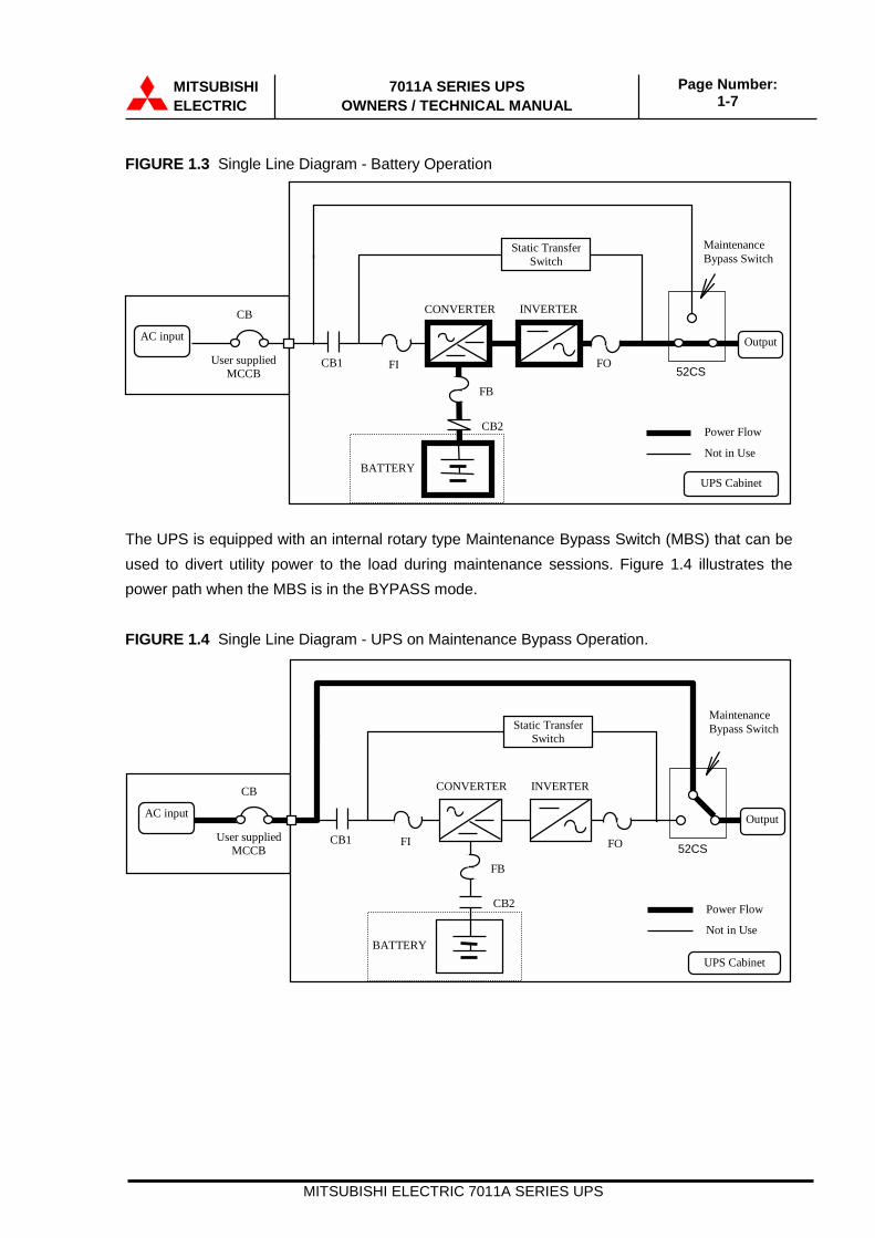
FIGURE 1.3 Single Line Diagram - Battery Operation
The UPS is equipped with an internal rotary type Maintenance Bypass Switch (MBS) that can beused to divert utility power to the load during maintenance sessions. Figure 1.4 illustrates thepower path when the MBS is in the BYPASS mode.
FIGURE 1.4 Single Line Diagram - UPS on Maintenance Bypass Operation.
UPS Cabinet
FB
BATTERY
CB2
Static TransferSwitch
Power Flow
Not in Use
FO
CONVERTER INVERTER
OutputAC input
CB
User suppliedMCCB
MaintenanceBypass Switch
CB1 FI 52CS
UPS Cabinet
FB
BATTERY
CB2
Static TransferSwitch
Power Flow
Not in Use
Output
CB1 FI FO
AC input
CB
User suppliedMCCB
CONVERTER INVERTER
MaintenanceBypass Switch
52CS

MITSUBISHI ELECTRIC 7011A SERIES UPS
MITSUBISHIELECTRIC
7011A SERIES UPSOWNERS / TECHNICAL MANUAL
Page Number:1-8
The rotary maintenance bypass switch is shown as 52CS in Figure 1.4. 52CS is a two positionfour point make-before-break transfer switch.
The two positions are identified as NORMAL and BYPASS. In the NORMAL position the load is fedby the UPS - either through the inverter or through the static bypass line. In the BYPASS positionthe load is powered by an external source such as the utility or a generator. This transfer operationmust be made while the UPS is in the static bypass mode.
For transfer procedure to place the UPS in maintenance bypass mode, or from bypass mode tonormal operation mode, refer to section 3.6 Maintenance Bypass Set-up Procedures.(For Service Personnel Only)
FIGURE 1.5 UPS Parts Location(6kVA)
.
1.Relay I/F PCBRYER-A
UPS moduleFRONT VIEW
Converter & Inverter
Battery
Display PCBDPAU-63
I/O Module
3.Module Connectionterminal
Cooling fan
2.Maintenance bypasstransfer switch
52CS
Main PCBUPFR-L

MITSUBISHI ELECTRIC 7011A SERIES UPS
MITSUBISHIELECTRIC
7011A SERIES UPSOWNERS / TECHNICAL MANUAL
Page Number:1-9
FIGURE 1.6 UPS Parts Location(8,10 and 12kVA)
Main PCBUPFR-L
1.Relay I/F PCBRYER-A
UPS moduleFRONT VIEW
Converter &Inverter
Battery
Cooling fan
Display PCBDPAU-63
I/O Module
3.Module Connectionterminal
2.Maintenance bypass transfer switch
52CS

MITSUBISHI ELECTRIC 7011A SERIES UPS
MITSUBISHIELECTRIC
7011A SERIES UPSOWNERS / TECHNICAL MANUAL
Page Number:1-10
FIGURE 1.7 UPS Parts Location (Rear view)
FIGURE 1.8 External I/F PCB RYER-A
8.D-sub25PinConnector
RYER-A9.External contact signal terminal block
7. RS232CD-sub Connector
Note
: Connection
Main control PCBUPFR-L
B- B+ G L1 N L2 L1 N L2(DC I/P) (AC O/P) (AC I/P)
1.External I/F PCBRYER-A
4. External batteryterminal AC Intput terminal
AC Output terminal
5.Field Wire Terminal Block
6. Grounding Bar
MITSUBISHI ELECTRIC 7011A SERIES UPS
MITSUBISHIELECTRIC
7011A SERIES UPSOWNERS / TECHNICAL MANUAL
Page Number:1-11
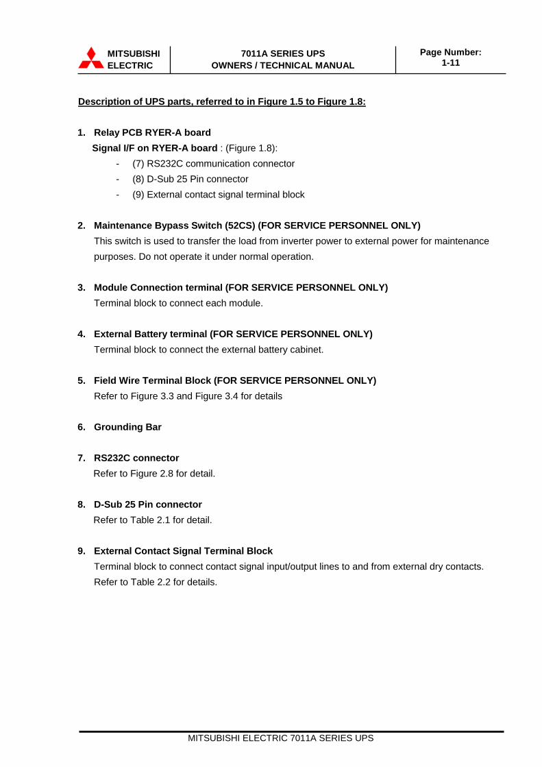
Description of UPS parts, referred to in Figure 1.5 to Figure 1.8:
1. Relay PCB RYER-A board Signal I/F on RYER-A board : (Figure 1.8):
- (7) RS232C communication connector- (8) D-Sub 25 Pin connector- (9) External contact signal terminal block
2. Maintenance Bypass Switch (52CS) (FOR SERVICE PERSONNEL ONLY)This switch is used to transfer the load from inverter power to external power for maintenancepurposes. Do not operate it under normal operation.
3. Module Connection terminal (FOR SERVICE PERSONNEL ONLY) Terminal block to connect each module.
4. External Battery terminal (FOR SERVICE PERSONNEL ONLY) Terminal block to connect the external battery cabinet.
5. Field Wire Terminal Block (FOR SERVICE PERSONNEL ONLY) Refer to Figure 3.3 and Figure 3.4 for details
6. Grounding Bar
7. RS232C connector Refer to Figure 2.8 for detail. 8. D-Sub 25 Pin connector Refer to Table 2.1 for detail. 9. External Contact Signal Terminal Block
Terminal block to connect contact signal input/output lines to and from external dry contacts.Refer to Table 2.2 for details.
MITSUBISHI ELECTRIC 7011A SERIES UPS
MITSUBISHIELECTRIC
7011A SERIES UPSOWNERS / TECHNICAL MANUAL
Page Number:1-12
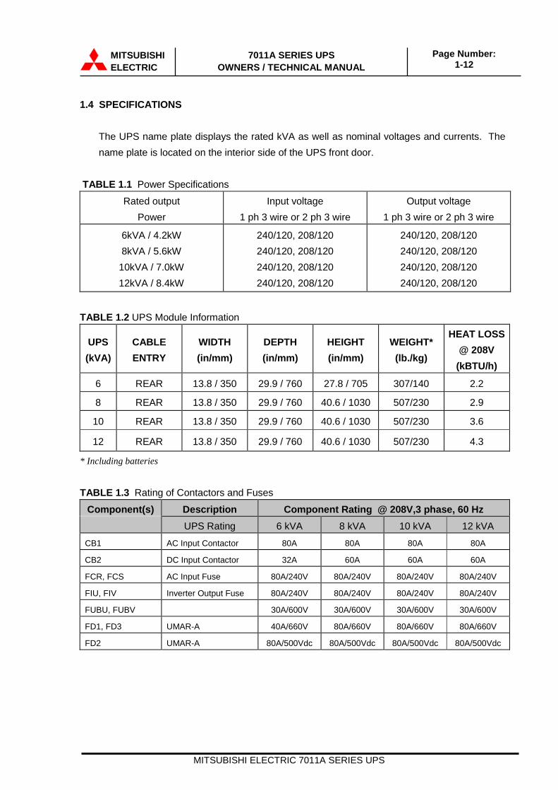
1.4 SPECIFICATIONS
The UPS name plate displays the rated kVA as well as nominal voltages and currents. Thename plate is located on the interior side of the UPS front door.
TABLE 1.1 Power SpecificationsRated output
PowerInput voltage
1 ph 3 wire or 2 ph 3 wireOutput voltage
1 ph 3 wire or 2 ph 3 wire
6kVA / 4.2kW8kVA / 5.6kW
10kVA / 7.0kW12kVA / 8.4kW
240/120, 208/120240/120, 208/120240/120, 208/120240/120, 208/120
240/120, 208/120240/120, 208/120240/120, 208/120240/120, 208/120
TABLE 1.2 UPS Module Information
UPS(kVA)
CABLEENTRY
WIDTH(in/mm)
DEPTH(in/mm)
HEIGHT(in/mm)
WEIGHT*(lb./kg)
HEAT LOSS@ 208V
(kBTU/h)
6 REAR 13.8 / 350 29.9 / 760 27.8 / 705 307/140 2.2
8 REAR 13.8 / 350 29.9 / 760 40.6 / 1030 507/230 2.9
10 REAR 13.8 / 350 29.9 / 760 40.6 / 1030 507/230 3.6
12 REAR 13.8 / 350 29.9 / 760 40.6 / 1030 507/230 4.3
* Including batteries
TABLE 1.3 Rating of Contactors and FusesComponent(s) Description Component Rating @ 208V,3 phase, 60 Hz
UPS Rating 6 kVA 8 kVA 10 kVA 12 kVACB1 AC Input Contactor 80A 80A 80A 80A
CB2 DC Input Contactor 32A 60A 60A 60A
FCR, FCS AC Input Fuse 80A/240V 80A/240V 80A/240V 80A/240V
FIU, FIV Inverter Output Fuse 80A/240V 80A/240V 80A/240V 80A/240V
FUBU, FUBV 30A/600V 30A/600V 30A/600V 30A/600V
FD1, FD3 UMAR-A 40A/660V 80A/660V 80A/660V 80A/660V
FD2 UMAR-A 80A/500Vdc 80A/500Vdc 80A/500Vdc 80A/500Vdc

MITSUBISHI ELECTRIC 7011A SERIES UPS
MITSUBISHIELECTRIC
7011A SERIES UPSOWNERS / TECHNICAL MANUAL
Page Number:1-13
TABLE 1.4 Detail of SpecificationsRated Output kVA 6 8 10 12Rated Output kW 4.2 5.6 7.0 8.4
AC INPUT CHARACTERISTICSConfiguration 1 phase 3 wire or 2 phase 3 wireVoltage 240/120V (1 phase), 208/120V (2 phase)Frequency 50 / 60 Hz +/-5%Reflected Current THD 4% typ. at 100% load; 7% typ. at 50% load
BATTERYType VRLARide Through 10min. at 100%
load15min. at 100%
load12min. at 100%
load10min. at 100%
loadNominal Voltage 216 VdcMinimum Voltage 173 VdcNumber of Cells 108
AC OUTPUTConfiguration 1 phase 3 wire or 2 phase 3 wireVoltage 240/120V (1 phase), 208/120V (2 phase)Voltage Stability +/-2% steady stateFrequency 50 / 60 HzFrequency Stability +/-0.01% in free running modePower Factor 0.7 nominalPower Factor range 0.7 ~ 1.0 lagging (within output kW rating)Voltage THD 2% typical THD at 100% Linear Load
5% typical THD at 100% non-linear loadTransient Response +/-3% typical at 100% load step
+/-1% typical at loss/return of AC power+/-3% typical at load transfer to/from static bypass
Transient Recovery 50 msVoltage Unbalance 2% typical at 100% unbalanced loadPhase Displacement 1deg. typical at 100% loadInverter Overload 150% for 1 minuteSystem Overload 150% for 1 minute, 1000% for 1 cycle (with bypass available)Bypass Overload 150% for 1 minute, 1000% for 1 cycleCrest Factor Capabilities 3:1
ENVIRONMENTALCooling Forced AirOperating Temperature 32°F ~ 104°F (0°C ~ 40°C). Recommended 59°F ~ 77°F (15°C ~ 25°C)Relative Humidity 5% ~ 95% Non CondensingAltitude 0 ~ 9000 feet No DeratingLocation Temperature-controlled, indoor area free of conductive contaminants
MITSUBISHI ELECTRIC 7011A SERIES UPS
MITSUBISHIELECTRIC
7011A SERIES UPSOWNERS / TECHNICAL MANUAL
Page Number:2-1
2.0 OPERATOR CONTROLS AND INDICATORS
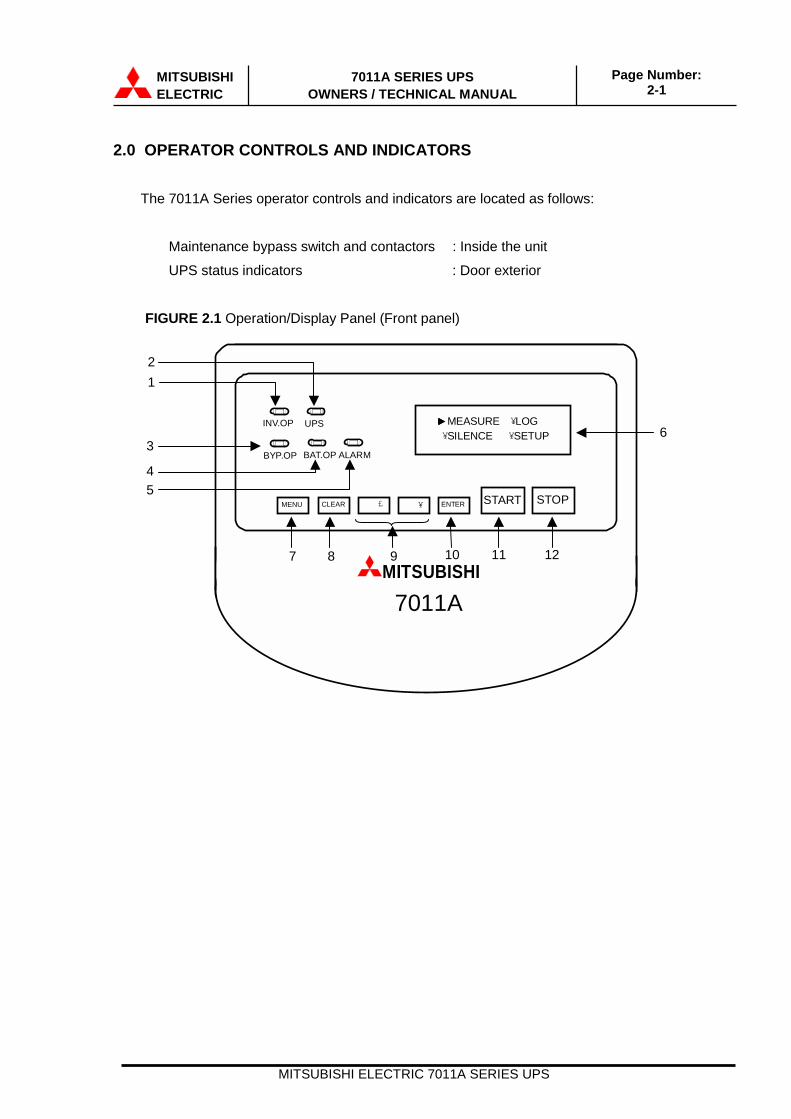
The 7011A Series operator controls and indicators are located as follows:
Maintenance bypass switch and contactors : Inside the unit
UPS status indicators : Door exterior
FIGURE 2.1 Operation/Display Panel (Front panel)
MEASURE ¥LOG ¥SILENCE ¥SETUP
INV.OP UPS
BYP.OP BAT.OP ALARM
� £ MENU ENTER CLEAR STOP START� ¥
MITSUBISHI 7011A
1
3
2
45
6
7 108 11 129
MITSUBISHI ELECTRIC 7011A SERIES UPS
MITSUBISHIELECTRIC
7011A SERIES UPSOWNERS / TECHNICAL MANUAL
Page Number:2-2
2.1 STATUS INDICATORS
1) Load on inverter [INV OP.] (green) Illuminated when power is supplied from inverter to the critical load.
2) [UPS] (green) Illuminated when UPS is ready to supply load.
3) Load on bypass [BYP OP.] (yellow) Illuminated when power is supplied to load devices by static bypass.
4) Battery operation [BAT OP.] (yellow) Illuminated when the battery is operating following an AC power failure.
5) [ALARM] (red) Illuminated when UPS is in fault mode, input abnormal, or overload.
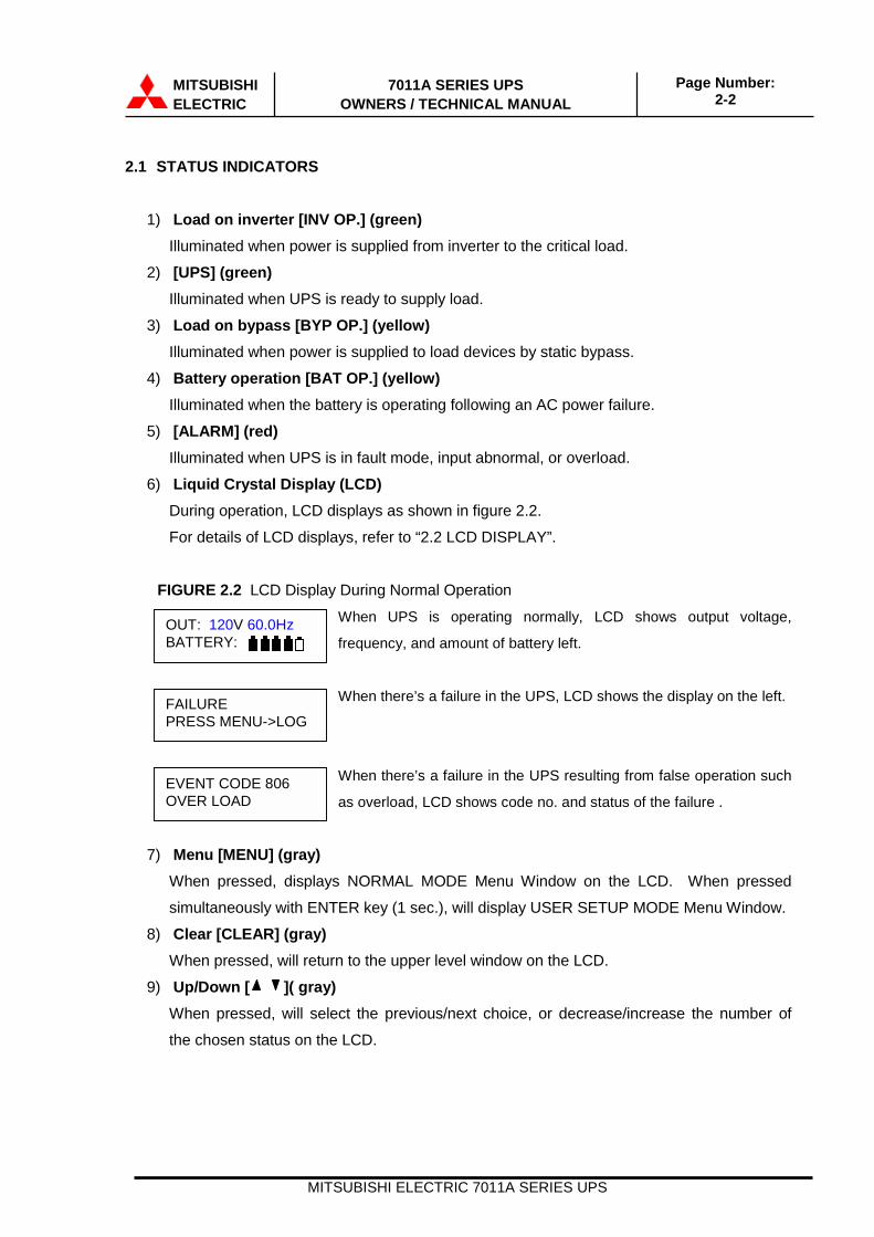
6) Liquid Crystal Display (LCD) During operation, LCD displays as shown in figure 2.2.
For details of LCD displays, refer to “2.2 LCD DISPLAY”.
FIGURE 2.2 LCD Display During Normal Operation
When UPS is operating normally, LCD shows output voltage,
frequency, and amount of battery left.
When there’s a failure in the UPS, LCD shows the display on the left.
When there’s a failure in the UPS resulting from false operation such
as overload, LCD shows code no. and status of the failure .
7) Menu [MENU] (gray) When pressed, displays NORMAL MODE Menu Window on the LCD. When pressed
simultaneously with ENTER key (1 sec.), will display USER SETUP MODE Menu Window.
8) Clear [CLEAR] (gray) When pressed, will return to the upper level window on the LCD.
9) Up/Down [ ]( gray) When pressed, will select the previous/next choice, or decrease/increase the number of
the chosen status on the LCD.
FAILUREPRESS MENU->LOG
EVENT CODE 806OVER LOAD
OUT: 120V 60.0HzBATTERY:

MITSUBISHI ELECTRIC 7011A SERIES UPS
MITSUBISHIELECTRIC
7011A SERIES UPSOWNERS / TECHNICAL MANUAL
Page Number:2-3
10) Enter [ENTER] (gray) When pressed, will fix the displayed value, and/or display the next window.
11) UPS start [START] (green) UPS start button. When pressed, the UPS starts to load from the inverter.
12) UPS stop [STOP] (red) UPS stop button. When pressed, the UPS can be stopped.
When pressed, will display Stop Mode Window. Then if pressed simultaneously with
ENTER button, the UPS will stop operation.
MITSUBISHI ELECTRIC 7011A SERIES UPS
MITSUBISHIELECTRIC
7011A SERIES UPSOWNERS / TECHNICAL MANUAL
Page Number:2-4
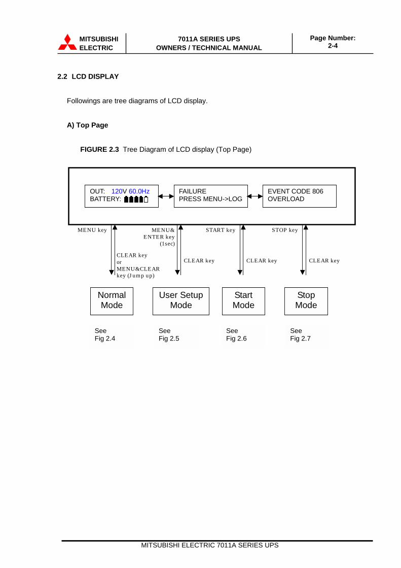
2.2 LCD DISPLAY
Followings are tree diagrams of LCD display.
A) Top Page
FIGURE 2.3 Tree Diagram of LCD display (Top Page)
SeeFig 2.4
SeeFig 2.5
SeeFig 2.6
SeeFig 2.7
OUT: 120V 60.0Hz BATTERY:
FAILURE PRESS MENU->LOG
EVENT CODE 806 OVERLOAD
MENU key
CLEAR key or MENU&CLEAR key (J ump up)
MENU&ENTER key
(1sec)
CLEAR key
START key
CLEAR key
STOP key
CLEAR key
Normal Mode
User SetupMode
Start Mode
Stop Mode

MITSUBISHI ELECTRIC 7011A SERIES UPS
MITSUBISHIELECTRIC
7011A SERIES UPSOWNERS / TECHNICAL MANUAL
Page Number:2-5
B) Normal Mode
FIGURE 2.4 Tree Diagram of LCD Display (Normal Mode)
BATTERY 216V CHARGE
Measure
OUT1 120V 60.0Hz OUT2 120V 60.0Hz
OUT1 100A 100% 12.0kW 100%
OUT2 100A 100% 12.0kW 100%
INPUT 240V 60.0Hz
Menu
Top P age
CLE AR key
MEASURE ¥LOG ¥SILENCE ¥SETUP
Manual(UP/DOWN Key)or Auto Scroll
Output Voltage
OUT VOLTAGE ADJ 0.0 -> +2.0%
Battery Check
BATTERY CHECK - CHECKING -
Time
MONTH/DATE /‘YEAR10 / 14 / ‘00
HOUR : MINUTE 17 : 28
Scroll Speed
SCROLL SPEED 1 -> 0 SEC
Bypass Operation
LOAD ON BYPASS? ON
¥SCROLL ¥BYPASS_OP
Setup
BATT_CHK ¥TIME ¥VOLT_ADJ¥NEXT>
Return here with Clear Key
Log
( 10 items / 10 pages )
( 1) 22:05 10/14 +271 INV1 O.C.
( 2) 22:04 10/14 +806 OVERLOAD
Next page
Measure OUT1:OUT2:
L1-NL2-N
Log +[code]:- [code]:
OccurredCleared
Set up BATT_CHKTIMEVOLT_ADJ:SCROLL:BYPASS_OP:
Start the self battery test operation.Set the day and time.Adjust the output voltage.Set the log page scroll speed.Select the output source.

MITSUBISHI ELECTRIC 7011A SERIES UPS
MITSUBISHIELECTRIC
7011A SERIES UPSOWNERS / TECHNICAL MANUAL
Page Number:2-6
C) User Setup Mode
FIGURE 2.5 Tree diagram of LCD Display (User Setup Mode)
ALARM:RESET:STOP_SET:
Audible alarm Enable / DisableFault clear and restart.Stop mode select (Output Stop orBypass Transfer)
D) Start Mode
FIGURE 2.6 Tree Diagram of LCD Display (Start Mode)
E) Stop Mode
FIGURE 2.7 Tree Diagram of LCD Display (Stop Mode)
When “Complete Shutdown” procedure is executed, all the output powerfrom the UPS will be shut off.
Alarm
AUDIBLE ALARM? ON
Stop Mode Setup
STOP MODE SETUP-OUTPUT STOP-
Power Save OP(Optional)
POWER SAVE ON -> OFF
(JAPANESE)
Language(Optional)
LANGUAGE ENGLISH
Reset
RESET PRESS CLEAR KEY
Return here with Clear Key
ALARM ¥STOP_SET¥RESET ¥NEXT>>
Top Page
CLEAR key
¥POWER ¥LANG
Start(Bypass Asynchronous)Start(When UPS is INV.OP.) LOAD ON INVERTER
LOAD INTERRUPT?YES
Top P age
CLEAR key
Start(When initializing) TRY AGAIN AFTER CHECKING LOG
Stop(When UPS is BYP.OP.)Stop(Bypass Synchronous)
Top Page
CLEAR key
STOP: PRESSSTOP & ENTER KEY
INTERRUPT TRANS?YES
LOAD ON BYPASS STOP+UP+DOWN key(5sec)
Stop(Bypass Asynchronous)
BYPASS ABNORMALUNABLE TO STOP
Complete Shutdown

MITSUBISHI ELECTRIC 7011A SERIES UPS
MITSUBISHIELECTRIC
7011A SERIES UPSOWNERS / TECHNICAL MANUAL
Page Number:2-7
2.3 RS232C CONNECTOR (External communication connector)This is an RS232C port for “Diamond-Link”* monitoring software. The layout of the connector
is shown in Figure 2.8. Connections not to exceed NEC Class 2.
FIGURE 2.9 RS-232C Connectors
Pin 1. : Not used
Pin 2. RXD : Receive data
Pin 3. TXD : Transmit data
Pin 4. DTR : Always high level
Pin 5. GND : Signal ground
Pin 6. : Not used
Pin 7. RTS : Always high level
Pin 8. : Not used
Pin 9. : Not used
* Consult MITSUBISHI ELECTRIC AUTOMATION, INC. for detail on “Diamond Link” monitoring
software and its capabilities.
D-SUB 9Pin�(male)
RYER-A
12345
6789

MITSUBISHI ELECTRIC 7011A SERIES UPS
MITSUBISHIELECTRIC
7011A SERIES UPSOWNERS / TECHNICAL MANUAL
Page Number:2-8
2.4 D-SUB 25 PIN CONNECTORUses dry contact on/off to express NORMAL, FAULT, ON BATTERY, BATTERY LOW, ON
BYPASS, ON INVERTER status. Connections not to exceed NEC Class 2.
TABLE 2.1 D-Sub 25 Pin connectorPin No. Signal I/O Pin No. Signal I/O
1 Failure A Contact Output 14 Output2 Failure A Contact com Output 15 Output3 Output 16 Output4 Battery Operation A Contact Output 17 Output5 Battery Operation com Output 18 Output6 Output 19 Output7 Battery Low Voltage A Contact Output 20 Output8 Battery Low Voltage A Contact com Output 21 Output9 Bypass Operation A Contact Output 22 Shut Off Input
10 Bypass Operation A Contact com Output 23 Shut Off common Input11 Inverter Operation A Contact Output 24 RE-EPO Input12 Inverter Operation A Contact com Output 25 RE-EPO common Input13 Output
FIGURE 2.10 D-sub 25 Pin Connectors
UPS
(User supplied)
>0.5sec
COM NO NC
COM NO NC
COM NO
Failure
Battery Operation
Battery Low
Bypass Operation
Inverter Operation
COM NO NC
COM NO NC
13 12 11 10 9 8 7 6 5 4 3 2 1
25 24 23 22 21 20 19 18 17 16 15 14
Remote Shut Off Siganl Imin < 20mA
7V - 15V
Remote EOP
RYER-A

MITSUBISHI ELECTRIC 7011A SERIES UPS
MITSUBISHIELECTRIC
7011A SERIES UPSOWNERS / TECHNICAL MANUAL
Page Number:2-9
2.5 EXTERNAL SIGNAL TERMINAL BLOCK (Option)
The UPS is equipped with a series of input/output terminals for the external annunciation of
alarms and the remote access of certain UPS functions. A functional description of the
input/output port is presented below. Layout of terminals is shown in Figure 2.10.
Connections not to exceed NEC Class 2.
FIGURE 2.11 External Signal Terminal Block
UPS
12
1011
89
76
54
32
1
9 – 10: BATTERY TEMPERATURE
5 – 6: RE-STARTUP
7 – 8: RE-SHUTDOWN
3 – 4: REMOTE EPO
1 –2: FAILURE
(User supplied dry contact)
RYER-A
Terminal Block

MITSUBISHI ELECTRIC 7011A SERIES UPS
MITSUBISHIELECTRIC
7011A SERIES UPSOWNERS / TECHNICAL MANUAL
Page Number:2-10
A) Output Contacts(for external alarm annunciation)Output contacts consist of form “A” dry type contacts. Rated capacity of all output
contacts is 30Vdc/1Adc. Operate all dry contacts at their rated values or lower. Figure
2.11 illustrates typical installation. The external relay can also be a lamp, LED,
computer, etc.
FIGURE 2.12 Control Wiring for External Contacts
NOTE: The UPS is equipped with a selectable output contact feature. Theabove alarms are the default settings. Contact MITSUBISHIELECTRIC AUTOMATION, INC. for setup information.
User supplied
Terminal
UPS Cabinet External to UPS Cabinet
Relay
Coil
NEC Class 2 Power Source
Relay Contact Terminal

MITSUBISHI ELECTRIC 7011A SERIES UPS
MITSUBISHIELECTRIC
7011A SERIES UPSOWNERS / TECHNICAL MANUAL
Page Number:2-11
B) Input Contacts(for remote access of UPS)External contacts are provided by the user of the UPS system. Terminal voltage at the
UPS is 24Vdc. Provide external dry contact accordingly.
CAUTION: Do not apply voltage to remote access input terminals. Damageto UPS may result.
Refer to Figure 2.12 for typical wiring configuration. Although this figure applies to the
RE-STARTUP terminals, the same wiring arrangement is used for RE-EPO; RE-
SHUTDOWN, Battery temperature.
FIGURE 2.13 Remote "Startup" Contact Connections
NOTE: In all cases, a switch having a protective cover is recommended inorder to reduce possibility of accidental operation.
User supplied
Startup
UPS Cabinet External to UPSCabinet
Relay
Coil
24VDC
Relay Coil current: 8.3mA
Common
Star t Swit ch
Use Momentary Switches Only

MITSUBISHIELECTRIC
7011A SERIES UPSOWNERS / TECHNICAL MANUAL
Page Number:3-1
MITSUBISHI ELECTRIC 7011A SERIES UPS
3.0 INSTALLATION AND OPERATION
3.1 TRANSPORTATION AND INSTALLATION
TABLE 3.1 How to transport and install the system
Transportation Installation
Transport unit with forklift. Pull out the UPS cabinet as shown in Figure 3.1
Fix the UPS unit in place using the four (4) leveling
f
NOTE: Do not transport in a horizontal position. Cabinets should bemaintained upright within +/- 15° of the vertical during handling.
3.2 HANDLINGThe UPS is shipped in export packaging. Remove the UPS from the package only when it is
ready for installation. Refer to Figure 3.1 for handling.
FIGURE 3.1 Handling
RAMPRoof of the package during shipping
5
12
3
4
Levelingfeet

MITSUBISHIELECTRIC
7011A SERIES UPSOWNERS / TECHNICAL MANUAL
Page Number:3-2
MITSUBISHI ELECTRIC 7011A SERIES UPS
3.3 INSTALLATION PROCEDURE
A) Note the load tolerance of the floorRefer to TABLE 3.1 for list of UPS weights:
TABLE 3.1 List of UPS weights (lb.)
UPS Capacity (kVA) 6 8 10 12
Weight (lb.) 307 507 507 507
B) Minimum clearance required for ventilationRight side 1.2" (30 mm) (not required when sidecars are used)
Left side 1.2" (30 mm) (not required when sidecars are used)
Back side 3.9" (100 mm)
Top side 23.5" (600 mm)
C) Space requirement for routine maintenanceAllow for the following space at the time of installation.
Front 39.2" (1000 mm)
Sides 1.2" (30 mm)
Rear 39.2" (1000 mm)
(3.9” (100mm) when cable connected at the rear side is drawn
from the front side)
FIGURE 3.1 Clearance for ventilation and maintenance
3.9" (100mm)
For Air exhaust
23.5" (600mm)For Maintenance
39.2" (1000mm)For Maintenance
MITSUBISHIELECTRIC
7011A SERIES UPSOWNERS / TECHNICAL MANUAL
Page Number:3-3
MITSUBISHI ELECTRIC 7011A SERIES UPS
3.3 PROCEDURE FOR CABLE CONNECTION (Refer to Table 3.2 for cable sizes.)1) Confirm the capacity of the UPS being installed. Identify the field terminal blocks as shown in
the appropriate Figure 3.2 or Figure 3.3-Figure 3.5.
2) Referring to Figure 3.4-Figure 3.5., connect the grounding conductors from the input serviceentrance to the UPS ground bar.
3) Confirm that an external input circuit breaker sized to protect both the rectifier input and thebypass lines is installed. Consult equipment nameplate for current ratings.
4) Connect the AC power source cables from the input service entrance to the UPS” INPUTpower terminals identified as L1, N, and L2 in Figure 3.3-Figure 3.5. Input cables must besized for an ampere rating larger than the maximum current capacity of the UPS. Refer toTable 3.2 for recommended cable sizes.
5) Refer to Table 3.2 for recommended cable sizes. Referring to Figure 3.3-Figure 3.5, connectUPS OUTPUT load terminals L1, N, and L2 to load distribution panel.
6) UPS equipment does not employ AC output overcurrent protection or disconnection devicesand must be provided at installation.
7) UPS equipment does not employ DC input overcurrent protection or disconnection devicesand must be provided at installation.
8) Connect external signal terminal block as needed. Refer to section 2.3 and Figure 2.9 forfunctional description. 12 AWG or less, shielded conductor is recommended.
9) Connect external BatteryRefer section 3.4.1.
10) Connect internal battery connector(s).
CAUTION: UPS power terminals are supplied with stud type fittings. It isrecommended that compression lugs be used to fasten allinput/output power cables. Refer to Table 3.3 for recommendedcompression lugs and appropriate crimping tool

MITSUBISHIELECTRIC
7011A SERIES UPSOWNERS / TECHNICAL MANUAL
Page Number:3-4
MITSUBISHI ELECTRIC 7011A SERIES UPS
TABLE 3.2 Recommended Cable Size and Torque RequirementsUPS Capacity Input Side *1 Output Side *1
(kVA) Cable Size Torque (in. lbs) Cable Size Torque (in. lbs)6kVA
(208V)10 AWG *2
or larger80
in. lbs10 AWG *2
or larger80
in. lbs8kVA
(208V)8 AWG *2
or larger80
in. lbs8 AWG *2
or larger80
in. lbs10kVA(208V)
6 AWG *2
or larger80
in. lbs6 AWG *2
or larger80
in. lbs12kVA(208V)
6 AWG *2
or larger80
in. lbs6 AWG *2
or larger80
in. lbs*1 - Voltage drop across power cables not to exceed 3% of nominal source voltage.*2 - Allowable ampere ratings based on 90 °C insulation at an ambient temperature of 40 °C.
No more than 3 conductors in a raceway without de-rating. Use copper conductors rated 90°C.
TABLE 3.3 Crimp Type Compression LugWireSize
WireStrand
Recommendation Crimp tool requiredBUNRNDY type Y35 or Y46
(Code) Class Vendor Cat. No. Color key Die index10 B BURNDY YAV10 T3BOX - -8 B BURNDY YA8C-L1 BOX RED 496 B BURNDY YA6C-L BOX BLUE 7 / 374
NOTE: When using crimp type lugs, the lugs should be crimped to thespecifications given in the manufacturer's instructions for bothcrimp tool and lug.
FIGURE 3.2 UPS Terminal Designation
Terminals:INPUTL1, N, L2
Terminals:OUTPUTL1, N, L2
OutputAC input
BATTERY
CB1 FO FI
CONVERTER INVERTER
UPS Module
CB2
FB52CS
Static TransferSwitch
B+B-
G

MITSUBISHIELECTRIC
7011A SERIES UPSOWNERS / TECHNICAL MANUAL
Page Number:3-5
MITSUBISHI ELECTRIC 7011A SERIES UPS
FIGURE 3.3 Terminal Block
FIGURE 3.4 Field Wire Terminal Block (6kVA) (Rear View)
I/O Module
Rectifier/Inverter Module
ALL POWER TERMINALSUSE 1/4” (6 MM) DIAMETER BOLTS
5. Field Wire Terminal Block
6. Grounding Bar
7. RS232C
9. External Signal Terminal Block (Optional: Cover Plate when not in use)
8. D-sub25Pin Connector
B- B+ G L1 N L2 L1 N L2(DC Input) (AC Output) (AC Input)
DC INPUT GROUND AC OUTPUT AC INPUT
B- B+ G L1 N L2 L1 N L2
216Vdc 120Vac 120Vac
208Vac or 240Vac
120Vac 120Vac
208Vac or 240VacUse for External Battery

MITSUBISHIELECTRIC
7011A SERIES UPSOWNERS / TECHNICAL MANUAL
Page Number:3-6
MITSUBISHI ELECTRIC 7011A SERIES UPS
FIGURE 3.5 Field Wire Terminal Block (8,10 and 12kVA) (Rear View)
ALL POWER TERMINALSUSE 1/4” (6 MM) DIAMETER BOLTS
I/O Module
Rectifier/Inverter Module
Rectifier/Inverter Module
7. RS232C
5. Field Wire Terminal Block
6. Grounding Bar
9. External Signal Terminal Block (Optional: Cover Plate when not in use)
8. D-sub25Pin Connector
B- B+ G L1 N L2 L1 N L2(DC Input) (AC Output) (AC Input)

MITSUBISHI ELECTRIC 7011A SERIES UPS
MITSUBISHIELECTRIC
7011A SERIES UPSOWNERS / TECHNICAL MANUAL
Page Number:3-7
FIGURE 3.6 Field Wire Connection (208V – 120V WYE, 2 phase, 3wire)
NOTE: Proper phase rotation must be observed when connecting input wires to L1 and L2.If code 803 occursSee next page.
Ground
Ground
208V-120VYLNL
External Battery Cabinet (If used)
Rear View
UPS Cabinet
B- B+ G L1 N L2 L1 N L2(DC Input) (AC Output) (AC Input)
NeutralBus bar
B- B+ G
RecommendCircuit
Breaker
Utility Power*1
*1 : Please refer to the page 3-10

MITSUBISHI ELECTRIC 7011A SERIES UPS
MITSUBISHIELECTRIC
7011A SERIES UPSOWNERS / TECHNICAL MANUAL
Page Number:3-8
Wire Connection (208V – 120V WYE, 2 phase, 3wire)
FIGURE 3.6.1 Correct connection
FIGURE 3.6.2 Incorrect connection-> Code 803 Displayed on LCD when UPS powered up.
UPS Must have Clockwise Phase Rotation if Error code 803 occurs, swap L1 and L2. (see figure 3.6.1 and 3.6.2)
DCINPUT
GROUND
AC OUTPUT AC INPUT
B- B+
G L1
N L2
L1
N L2
DCINPUT
GROUND
AC OUTPUT AC INPUT
B- B+
G L1
N L2
L1
N L2

MITSUBISHI ELECTRIC 7011A SERIES UPS
MITSUBISHIELECTRIC
7011A SERIES UPSOWNERS / TECHNICAL MANUAL
Page Number:3-9
FIGURE 3.7 Field Wire Connection (240V – 120V, 1 phase, 3wire)
Ground
Ground
240V-120VLNL
External Battery Cabinet (If used)
Rear View
UPS Cabinet
B- B+ G L1 N L2 L1 N L2(DC Input) (AC Output) (AC Input)
NeutralBus bar
B- B+ G
RecommendCircuit
Breaker
Utility Power*1
*1 : Please refer to the page 3-10

MITSUBISHIELECTRIC
7011A SERIES UPSOWNERS / TECHNICAL MANUAL
Page Number:3-10
MITSUBISHI ELECTRIC 7011A SERIES UPS
3.4 INSTALLATION PROCEDURE FOR BATTERY
Installation procedures of the batteries are shown on the next page.
Please refer to the following when installing and maintaining batteries:
1. Servicing of batteries should be performed or supervised by personnel
knowledgeable of batteries and the required precautions. Keep unauthorized
personnel away from batteries.
2. When installing or replacing batteries, install or replace with the same number
and type per Table 3.4
TABLE 3.4 Type and Number of Battery
Type Manufacturer Number
6kVA HV7-12 Shin-Kobe 18
8,10 and 12kVA HV7-12 Shin-Kobe 36
CAUTION - Do not dispose of battery or batteries in a fire. The battery may
explode.
CAUTION - Do not open or mutilate the battery or batteries. Released electrolyte
is harmful to the skin and eyes and may be toxic.
CAUTION - A battery can present a risk of electrical shock and high short circuit
current. The following precautions should be observed when working
on batteries:
� Remove watches, rings, or other metal objects.
� Use tools with insulated handles.
� Wear rubber gloves and boots.
� Do not lay tools or metal parts on top of batteries.
� Disconnect charging source prior to connecting or disconnecting
battery terminals.

MITSUBISHIELECTRIC
7011A SERIES UPSOWNERS / TECHNICAL MANUAL
Page Number:3-11
MITSUBISHI ELECTRIC 7011A SERIES UPS
3.4.1 PROCEDURE FOR EXTERNAL BATTERY CONNECTION (OPTIONAL)
1. Installation procedure
Please refer to the figure 3.6 or 3.7 for connection.
Must connect external battery before internal battery is connected.
2. Set-up procedure
Please confirm the capacity “Ah (ampere hour) ” of the external battery cabinet.
Refer to the Page 3-16 for the Ah (ampere hour) setup on the UPS.
MITSUBISHIELECTRIC
7011A SERIES UPSOWNERS / TECHNICAL MANUAL
Page Number:3-12
MITSUBISHI ELECTRIC 7011A SERIES UPS
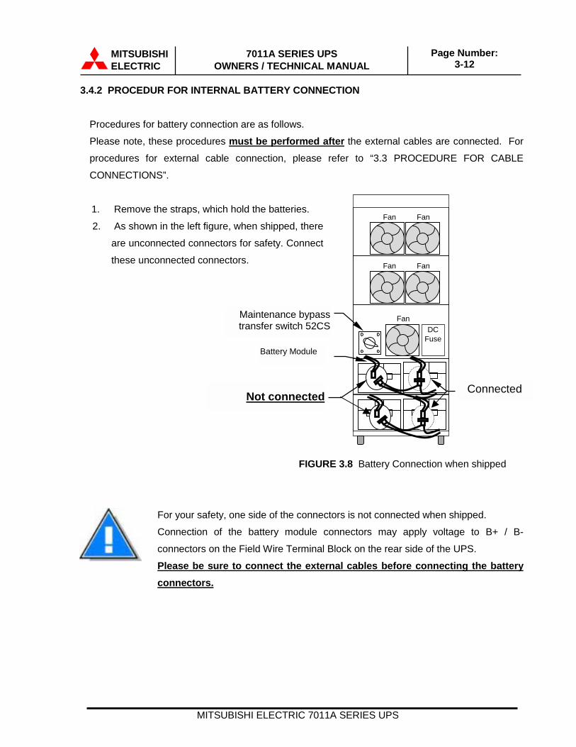
3.4.2 PROCEDUR FOR INTERNAL BATTERY CONNECTION
Procedures for battery connection are as follows.
Please note, these procedures must be performed after the external cables are connected. For
procedures for external cable connection, please refer to “3.3 PROCEDURE FOR CABLE
CONNECTIONS”.
1. Remove the straps, which hold the batteries.
2. As shown in the left figure, when shipped, there
are unconnected connectors for safety. Connect
these unconnected connectors.
FIGURE 3.8 Battery Connection when shipped
For your safety, one side of the connectors is not connected when shipped.
Connection of the battery module connectors may apply voltage to B+ / B-
connectors on the Field Wire Terminal Block on the rear side of the UPS.
Please be sure to connect the external cables before connecting the batteryconnectors.
Fan Fan
FanDC
Fuse
Fan Fan
Battery Module
ConnectedNot connected
Maintenance bypass transfer switch 52CS

MITSUBISHIELECTRIC
7011A SERIES UPSOWNERS / TECHNICAL MANUAL
Page Number:3-13
MITSUBISHI ELECTRIC 7011A SERIES UPS
3.5 OPERATING PROCEDURES
A) UPS Initial Startup ProcedurePlease be sure to confirm the internal maintenance bypass switch 52CS on“NORMAL” position before turn on AC input power.
This procedure is only performed during initial start-up.
B) UPS Start-up Procedure1. Press and Hold “START” button for 0.5 seconds2. The “INV.OP.” LED illuminates and the Inverter starts.
C) Bypass Operation Procedure1. Press “MENU” button and then select “BYPASS_OP.” and press ENTER button.2. Press “ “ or “ “ until the display shows “YES”, and then press ENTER button.3. “BYP.OP.” LED illuminates and the UPS will be in bypass operation.
WARNING: Verify the load is OFF if the next step is to be performed .
NOTE: Power to the critical load is supplied through the static bypass line.Power to the critical load will be lost after execution of the next step.The load will drop.
Enter
Enter
Enter
UPS START?YES
MONTH/DATE /YEAR10 / 14 / 00
HOUR : MINUTE17 : 28
AC Input power ON
Select YES.
Select HOUR and MINUTE.
UPS Normal operation.OUT: 120V 60.0HzBATTERY:
Select MONTH, DATE, and YEAR.

MITSUBISHIELECTRIC
7011A SERIES UPSOWNERS / TECHNICAL MANUAL
Page Number:3-14
MITSUBISHI ELECTRIC 7011A SERIES UPS
4. If turning off all power to the critical load is desired, open the AC Input Circuit Breaker (User
supplied.).
CAUTION: In bypass mode, all UPS power terminals are still alive. Lethalvoltages are present. De-energize all external sources of AC andDC power before handling UPS.
D) UPS Shutdown Procedure1. If a total UPS module (inverter and rectifier) shutdown is required, press the "STOP" button
on the front panel.
2. Then STOP Mode window will appear on the LCD.
3. Press the “STOP” and “ENTER” buttons simultaneously.
4. The UPS will shutdown and no power is supplied to the load.
WARNING: With this operation, although all output power from the UPS isshutdown, it is necessary to manually open the input circuitbreaker (user supplied), to remove the input power to the UPS

MITSUBISHIELECTRIC
7011A SERIES UPSOWNERS / TECHNICAL MANUAL
Page Number:3-15
MITSUBISHI ELECTRIC 7011A SERIES UPS
3.6 MAINTENANCE BYPASS SET-UP PROCEDURES (For Service Personnel Only)
A) Transfer of load from inverter to maintenance bypass1. Press “MENU” button and then select “BYPASS_OP.” and press ENTER button.
2. Press “ “ or “ “ until the display shows “YES”, and then press ENTER button.
3. “BYP.OP.” LED illuminates and the UPS will be in bypass operation.
WARNING: Do not transfer to Maintenance Bypass Mode unlessthe inverter is not running --- that is the UPS is in StaticBypass Mode.
4. After confirming that the “BYP.OP.” LED is illuminated, rotate 52CS clockwise to the
“TRANSFER” position (Do not rotate 52CS if the “BYP.OP.” LED is NOT illuminated).
5. Then rotate 52CS clockwise to the “WAIT” position and after that push & rotate to the
“BYPASS” position.
6. Transfer complete. Load is now powered from the external source.
B) Transfer of load from maintenance bypass to inverter1. Rotate 52CS counterclockwise from the “BYPASS” position to the “WAIT” position, and wait
10 seconds until the LCD on the front panel displays the top page.
WARNING: Do not proceed to the next step until the LCD on thefront panel displays the top page.
2. After confirming that the LCD on the front panel displays the top page, pull & rotate 52CS
counterclockwise to the “TRANSFER” position, and then rotate to the “NORMAL” position.
3. On the UPS, press and hold the “START” button for 0.5 seconds. The “INV.OP.” LED should
illuminate.
4. Transfer complete. Load now powered by the inverter.
MITSUBISHIELECTRIC
7011A SERIES UPSOWNERS / TECHNICAL MANUAL
Page Number:3-16
MITSUBISHI ELECTRIC 7011A SERIES UPS
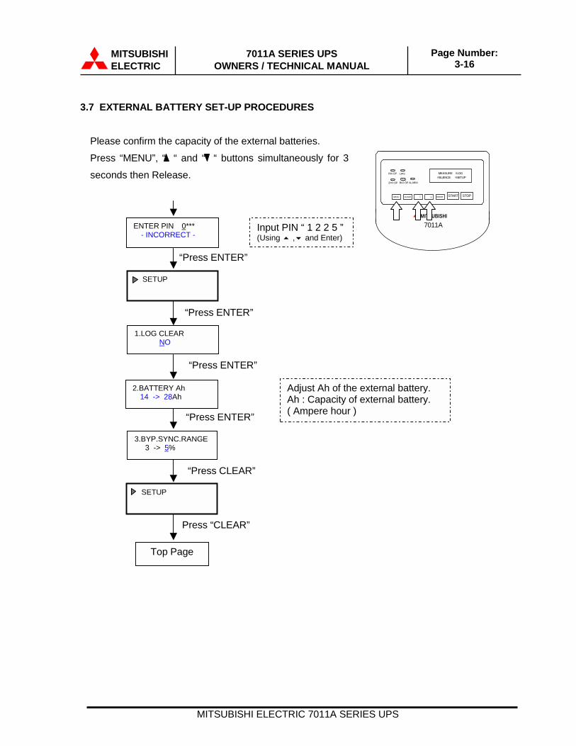
3.7 EXTERNAL BATTERY SET-UP PROCEDURES
Please confirm the capacity of the external batteries.
Press “MENU”, “ “ and “ “ buttons simultaneously for 3
seconds then Release.
ENTER PIN �0***- INCORRECT -
SETUP
2.BATTERY Ah14 -> 28Ah
1.LOG CLEAR NO
Input PIN “ 1 2 2 5 ”(Using � ,� and Enter)
Adjust Ah of the external battery.Ah : Capacity of external battery.( Ampere hour )
“Press ENTER”
3.BYP.SYNC.RANGE 3 -> 5%
SETUP
Top Page
Press “CLEAR”
MEASURE ¥LOG ¥SILENCE ¥SETUP
INV.OP UPS
BYP.OP BAT.OP ALARM
� £ MENU ENTER CLEAR STOP START � ¥
MITSUBISHI 7011A
“Press ENTER”
“Press ENTER”
“Press ENTER”
“Press CLEAR”

MITSUBISHIELECTRIC
7011A SERIES UPSOWNERS / TECHNICAL MANUAL
Page Number:4-1
MITSUBISHI ELECTRIC 7011A SERIES UPS
4.0 RESPONSE TO UPS FAILURE
Press the “MENU” button on the front panel. Then select
“SILENCE” and press the “ENTER” button.
Select “LOG” on the front panel and press “ENTER” button.
Record fault code on a piece of paper. Refer to the list of fault
codes for a description of the error. See section 6 For fault
codes
Take necessary action per the list of fault codes in section 6 of
this manual.
If Service is needed contact the Authorized Mitsubishi Service
Representative or call Mitsubishi at:
1-800-887-7830.
NOTEThe error code indicated on the LCD at the time of UPS alarm condition isvery important. In order to minimize repair time, please include thisinformation along with the operation status and load status, on allcorrespondence with Mitsubishi’s field service group.
UPS FAULT
Annunciator Silence
Recording of Fault
Primary Action
Information to Service Center

MITSUBISHI ELECTRIC 7011A SERIES UPS
MITSUBISHIELECTRIC
7011A SERIES UPSOWNERS / TECHNICAL MANUAL
Page Number:5-1
5.0 PARTS REPLACEMENT
Contact Mitsubishi or its Authorized Service Center on all issues regarding the replacement of
parts.
A) Battery Battery lifetime may vary according to the frequency of use and the average ambient
operating temperature. Battery end of life is defined as the state of charge resulting in an
ampere-hour capacity less than, or equal to, 80% of nominal capacity. Replace battery if
capacity is within this percentage.
B) UPS Component Parts Contact Mitsubishi or its Authorized Service Center for a complete parts replacement
schedule. Recommended replacement time interval varies with operating environment.
Contact Mitsubishi or its Authorized Service Center for specific application recommendations.
MITSUBISHIELECTRIC
7011A SERIES UPSOWNERS / TECHNICAL MANUAL
Page Number:6-1
MITSUBISHI ELECTRIC 7011A SERIES UPS
6.0 FAULT CODES
This section covers the fault codes, their description and required action.
At time of error :
A) Verify and record the occurrence of the alarm. Note fault code on the LCD.
Contact Mitsubishi Electric Automation, Inc. at 1-800-887-7830.
B) If the External AC Input Circuit Breaker (MCCB) is in the trip state, depress the toggle
to reset the breaker before re-closing.
MITSUBISHI ELECTRIC
7011A SERIES UPSOWNERS / TECHNICAL MANUAL
Page Number: 6-2
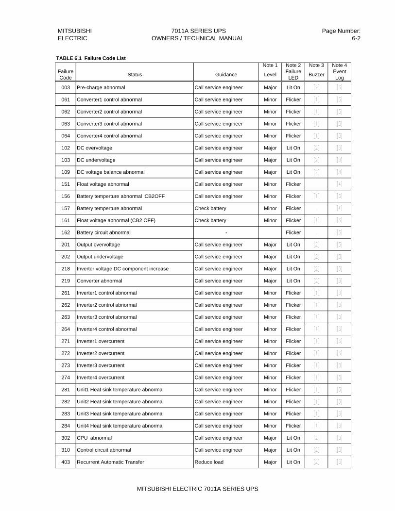
TABLE 6.1 Failure Code ListNote 1 Note 2 Note 3 Note 4
Failure Code Status Guidance Level Failure
LED Buzzer EventLog
003 Pre-charge abnormal Call service engineer Major Lit On
061 Converter1 control abnormal Call service engineer Minor Flicker
062 Converter2 control abnormal Call service engineer Minor Flicker
063 Converter3 control abnormal Call service engineer Minor Flicker
064 Converter4 control abnormal Call service engineer Minor Flicker
102 DC overvoltage Call service engineer Major Lit On
103 DC undervoltage Call service engineer Major Lit On
109 DC voltage balance abnormal Call service engineer Major Lit On
151 Float voltage abnormal Call service engineer Minor Flicker
156 Battery temperture abnormal CB2OFF Call service engineer Minor Flicker
157 Battery temperture abnormal Check battery Minor Flicker
161 Float voltage abnormal (CB2 OFF) Check battery Minor Flicker
162 Battery circuit abnormal - Flicker
201 Output overvoltage Call service engineer Major Lit On
202 Output undervoltage Call service engineer Major Lit On
218 Inverter voltage DC component increase Call service engineer Major Lit On
219 Converter abnormal Call service engineer Major Lit On
261 Inverter1 control abnormal Call service engineer Minor Flicker
262 Inverter2 control abnormal Call service engineer Minor Flicker
263 Inverter3 control abnormal Call service engineer Minor Flicker
264 Inverter4 control abnormal Call service engineer Minor Flicker
271 Inverter1 overcurrent Call service engineer Minor Flicker
272 Inverter2 overcurrent Call service engineer Minor Flicker
273 Inverter3 overcurrent Call service engineer Minor Flicker
274 Inverter4 overcurrent Call service engineer Minor Flicker
281 Unit1 Heat sink temperature abnormal Call service engineer Minor Flicker
282 Unit2 Heat sink temperature abnormal Call service engineer Minor Flicker
283 Unit3 Heat sink temperature abnormal Call service engineer Minor Flicker
284 Unit4 Heat sink temperature abnormal Call service engineer Minor Flicker
302 CPU abnormal Call service engineer Major Lit On
310 Control circuit abnormal Call service engineer Major Lit On
403 Recurrent Automatic Transfer Reduce load Major Lit On
MITSUBISHI ELECTRIC 7011A SERIES UPS

MITSUBISHI ELECTRIC
7011A SERIES UPSOWNERS / TECHNICAL MANUAL
Page Number: 6-3
Note 1 Note 2 Note 3 Note 4Failure Code Status Guidance Level Failure
LED Buzzer EventLog
454 Module temperature high Reduce room temperature Minor Flicker
455 Bypass circuit abnormal Call service engineer Minor Flicker
456 Bypass Overload Reduce load Minor Flicker
801 Input power source abnormal 85V-144V deviation frequency 7% deviation - Alarm Flicker
803 Input wire connection abnormal Swap L1 and L2 Alarm Lit On
806 Overload status Check load Alarm Flicker
807 OverKW Check load Alarm Flicker
808 Overload warning Reduce load Alarm Flicker
809 OverKW warning Reduce load Alarm Flicker
810 Instant overload - Alarm
812 Input voltage abnormal +/- 10 deviation or (energy conservation setting +/- 25% deviation) - Alarm
814 Input frequrency abnormal (Due to setting) Check input frequency Alarm Flicker
817 EPO - Alarm Flicker
834 Battery depleted - Alarm Flicker
835 Battery deplete warning Reduce load Alarm Flicker
837 Unit quantity mismatch Call service engineer Alarm Flicker
Note 1) Level "Major" is defined as a major failure. Load transferred from inverter to the static bypass line. "Minor" is defined as a minor failure. UPS continues to operate normally, but cause of alarm must be identified.
Note 2 Failure LED Indicates one of two possible LED illumination patterns - continuously on (lit) or intermittent (flicker).
Note 3) Buzzer (Audible annunciator) [1]:Intermittent Sound [2]:Continuous Sound
Note 4 Event log In case of major failures, log 10 items after the failure.[3]: Log time and item name at occasion. In some case, isn't logged.[4]: Log time and item name at occasion and clearing.
MITSUBISHI ELECTRIC 7011A SERIES UPS
MITSUBISHIELECTRIC
7011A SERIES UPSOWNERS / TECHNICAL MANUAL
Page Number:7-1
MITSUBISHI ELECTRIC 7011A SERIES UPS
7.0 WARRANTY & OUT OF WARRANTY SERVICE
The Mitsubishi Electric UPS Systems Group Service Department has many Authorized Service
Centers placed strategically throughout the US, Canada and Latin America. For both in warranty
and out of warranty service, please contact Mitsubishi Electric Automation, Inc. at (847) 478-2643.
To register your UPS for warranty purposes, please complete the warranty registration form and
fax it to the Mitsubishi Electric UPS Systems Group, Service Department fax line shown on the
registration form. (Next page)
For warranty purposes, it is essential that any and all service work that may be required on your
Mitsubishi brand UPS equipment is performed by a Mitsubishi Electric Authorized Service Center.
The use of non-authorized service providers may void your warranty.
Mitsubishi Electric Automation Inc,UPS Systems Group Service Department
500 Corporate Woods Parkway,Vernon Hills, Illinois 60061, USAPhone: (847) 478-2643Fax: (847) 478-2290

MITSUBISHIELECTRIC
7011A SERIES UPSOWNERS / TECHNICAL MANUAL
Page Number:7-2
MITSUBISHI ELECTRIC 7011A SERIES UPS
Mitsubishi Electric Automation, Inc.UNINTERRUPTIBLE POWER SUPPLIES500 Corporate Woods Parkway, Vernon Hills, IL 60061Phone: (847) 478-2643, Fax: (847) 478-2290
UPS Warranty Registration__ Register UPS for Warranty _ _ Address Change
To validate the Warranty on your UPS this form must be filled out completely byCustomer and returned.
CUSTOMER INFORMATIONYour Name: Job Title:
Company Name:
Division / Department:
Address:
City: State: Zip Code:
Country: Province:
Business Phone: Ext: Fax:
E-Mail: @
Internet Address:
UPS Model #: Capacity (kVA): UPS Serial #:
Start-Up Date: / /
Authorized Mitsubishi Service Company (if known):
Signature: Date: / /
Number of Employees at This Location is:Which ONE of These Best Describes Your Organization’sPrimary Business Classification?
__ 1 – 19__ 20 –49__ 50 – 99
__ 100 – 249__ 250 - 499__ 500 - 999
__1000 or more{Energy Producer} __ Utility __ Alternate Energy{Manufacturing Co.} __ OEM __ Process __ Consumer Goods __ Electronics __ Power Quality Equipment__ Commercial Business__ Electrical Contractor__ Healthcare__ Internet__ Education/Univ. Service
{Service} __ Consulting __ Engineering __ Outsourcing __ Financial/Legal/Insurance{Government} __ Military __ Municipals __ Federal/State/Local__ Communications__ Distributors/Reps__ Other __________________
Overall how was Start-Up performed:__Unsatisfactory __ Satisfactory __ Exceeded Expectations
Would you like to receive future product updates and news?__Yes __ No
After Start-Up has been done Fax completed Form to:(847) 478-2290