unified facilities criteria (ufc) - wbdg unified facilities criteria (ufc) ... this ufc and provides...
TRANSCRIPT

UFC 4-121-10N 16 January 2004
UNIFIED FACILITIES CRITERIA (UFC)
DESIGN: AIRCRAFT FIXED POINT UTILITY SYSTEMS
APPROVED FOR PUBLIC RELEASE; DISTRIBUTION UNLIMITED

UFC 4-121-10N 16 January 2004
UNIFIED FACILITIES CRITERIA (UFC)
DESIGN: AIRCRAFT FIXED POINT UTILITY SYSTEMS
Any copyrighted material included in this UFC is identified at its point of use. Use of the copyrighted material apart from this UFC must have the permission of the copyright holder. U.S. ARMY CORPS OF ENGINEERS NAVAL FACILITIES ENGINEERING COMMAND (Preparing Activity) AIR FORCE CIVIL ENGINEERING SUPPORT AGENCY Record of Changes (changes indicated by \1\ ... /1/ ) Change No. Date Location
UFC 4-121-10N 16 January 2004
FOREWORD The Unified Facilities Criteria (UFC) system is prescribed by MIL-STD 3007 and provides planning, design, construction, sustainment, restoration, and modernization criteria, and applies to the Military Departments, the Defense Agencies, and the DoD Field Activities in accordance with USD(AT&L) Memorandum dated 29 May 2002. UFC will be used for all DoD projects and work for other customers where appropriate. All construction outside of the United States is also governed by Status of forces Agreements (SOFA), Host Nation Funded Construction Agreements (HNFA), and in some instances, Bilateral Infrastructure Agreements (BIA.) Therefore, the acquisition team must ensure compliance with the more stringent of the UFC, the SOFA, the HNFA, and the BIA, as applicable. UFC are living documents and will be periodically reviewed, updated, and made available to users as part of the Services’ responsibility for providing technical criteria for military construction. Headquarters, U.S. Army Corps of Engineers (HQUSACE), Naval Facilities Engineering Command (NAVFAC), and Air Force Civil Engineer Support Agency (AFCESA) are responsible for administration of the UFC system. Defense agencies should contact the preparing service for document interpretation and improvements. Technical content of UFC is the responsibility of the cognizant DoD working group. Recommended changes with supporting rationale should be sent to the respective service proponent office by the following electronic form: Criteria Change Request (CCR). The form is also accessible from the Internet sites listed below. UFC are effective upon issuance and are distributed only in electronic media from the following source: • Whole Building Design Guide web site http://dod.wbdg.org/. Hard copies of UFC printed from electronic media should be checked against the current electronic version prior to use to ensure that they are current. AUTHORIZED BY: ______________________________________ DONALD L. BASHAM, P.E. Chief, Engineering and Construction U.S. Army Corps of Engineers
______________________________________DR. JAMES W WRIGHT, P.E. Chief Engineer Naval Facilities Engineering Command
______________________________________ KATHLEEN I. FERGUSON, P.E. The Deputy Civil Engineer DCS/Installations & Logistics Department of the Air Force
______________________________________Dr. GET W. MOY, P.E. Director, Installations Requirements and Management Office of the Deputy Under Secretary of Defense (Installations and Environment)
UFC 4-121-10N 16 January 2004
i
CONTENTS
Page CHAPTER 1 INTRODUCTION Paragraph 1-1 PURPOSE AND SCOPE ....................................................... 1-1
1-2 APPLICABILITY..................................................................... 1-1 1-2.1 General Building Requirements ............................................. 1-1 1-2.2 Safety .................................................................................... 1-1 1-2.3 Fire Protection ....................................................................... 1-1 1-2.4 Antiterrorism/Force Protection ............................................... 1-1 1-3 REFERENCES ...................................................................... 1-1
APPENDIX A MIL-HDBK 1028/6A……………...................…………………… A-1
UFC 4-121-10N 16 January 2004
1-1
CHAPTER 1
INTRODUCTION 1-1 PURPOSE AND SCOPE. This UFC is comprised of two sections. Chapter 1 introduces this UFC and provides a listing of references to other Tri-Service documents closely related to the subject. Appendix A contains the full text copy of the previously released Military Handbook (MIL-HDBK) on this subject. This UFC serves as criteria until such time as the full text UFC is developed from the MIL-HDBK and other sources.
This UFC provides general criteria for the design of aircraft fixed point utility systems.
Note that this document does not constitute a detailed technical design, maintenance or operations manual, and is issued as a general guide to the considerations associated with the design of aircraft fixed point utility systems. 1-2 APPLICABILITY. This UFC applies to all Navy service elements and Navy contractors; Army service elements should use the references cited in paragraph 1-3 below; all other DoD agencies may use either document unless explicitly directed otherwise. 1-2.1 GENERAL BUILDING REQUIREMENTS. All DoD facilities must comply with UFC 1-200-01, Design: General Building Requirements. If any conflict occurs between this UFC and UFC 1-200-01, the requirements of UFC 1-200-01 take precedence. 1-2.2 SAFETY. All DoD facilities must comply with DODINST 6055.1 and applicable Occupational Safety and Health Administration (OSHA) safety and health standards. NOTE: All NAVY projects, must comply with OPNAVINST 5100.23 (series), Navy Occupational Safety and Health Program Manual. The most recent publication in this series can be accessed at the NAVFAC Safety web site: www.navfac.navy.mil/safety/pub.htm. If any conflict occurs between this UFC and OPNAVINST 5100.23, the requirements of OPNAVINST 5100.23 take precedence. 1-2.3 FIRE PROTECTION. All DoD facilities must comply with UFC 3-600-01, Design: Fire Protection Engineering for Facilities. If any conflict occurs between this UFC and UFC 3-600-01, the requirements of UFC 3-600-01 take precedence. 1-2.4 ANTITERRORISM/FORCE PROTECTION. All DoD facilities must comply with UFC 4-010-01, Design: DoD Minimum Antiterrorism Standards for Buildings. If any conflict occurs between this UFC and UFC 4-010-01, the requirements of UFC 4-010-01 take precedence. 1-3 REFERENCES. The following Tri-Service publications have valuable information on the subject of this UFC. When the full text UFC is developed for this
UFC 4-121-10N 16 January 2004
1-1
subject, applicable portions of these documents will be incorporated into the text. The designer is encouraged to access and review these documents as well as the references cited in Appendix A. 1. US Army Corps of Engineers USACE TL 1110-3-430, Design of U.S.
Commander Army Airfield Aircraft Mooring and USACE Publication Depot Grounding Points for Rotary Wing ATTN: CEIM-IM-PD Aircraft, 23 September 1991 2803 52nd Avenue Hyattsville, MD 20781-1102 (301) 394-0081 fax: 0084 [email protected]
http://www.usace.army.mil/inet/usace-docs/

UFC 4-121-10N 16 January 2004
A-1
APPENDIX A
MIL-HDBK 1028/6A AIRCRAFT FIXED POINT UTILITY SYSTEMS

MIL-HDBK-1028/6 31 MAY 1996
SUPERSEDING MIL-HDBK-1028/6 30 SEPTEMBER 1988
MILITARY HANDBOOK
AIRCRAFT FIXED POINT UTILITY SYSTEMS
AMSC N/A AREA FACR
DISTRIBUTION STATEMENT A. APPROVED FOR PUBLIC RELEASE: DISTRIBUTION ISUNLIMITED.
INCH-POUND

MIL-HDBK 1028/6A
ii
ABSTRACT
This handbook provides basic design guidance for aircraft ground powerfacilities Category Code 149-15. It has been developed from extensive re-evaluation of facilities and is intended for use by experienced architectsand engineers. The contents include preliminary design data for thecentral utilities supply, distribution, and aircraft ground power fixedpoint (permanently located) service areas. Specific data are given forengine starting air, environmental control system cooling air,preconditioned cooling air for hangar aircraft, compressed air formaintenance operations, 400 Hz and 60 Hz electrical power distributionsystems.
MIL-HDBK 1028/6A
iii
FOREWORD
This handbook has been developed from an evaluation of facilities in theshore establishment, from surveys of the availability of new materials andconstruction methods, and from selection of the best design practices ofthe Naval Facilities Engineering Command (NAVFACENGCOM), other Governmentagencies, and the private sector. This handbook was prepared using, to themaximum extent feasible, national professional society, association, andinstitute standards. Deviations from this criteria, in the planning,engineering, design, and construction of Naval shore facilities, cannot bemade without prior approval of NAVFACENGCOM Criteria Office, Code 15C.
Design cannot remain static any more than can the functions it serves orthe technologies it uses. Accordingly, recommendations for improvement areencouraged and should be furnished to Commanding Officer, SouthernDivision,, Naval Facilities Engineering Command, Code 0741, P.O. Box190010, North Charleston, SC 29419-9010; telephone (803) 820-7404.
THIS HANDBOOK SHALL NOT BE USED AS A REFERENCE DOCUMENT FOR PROCUREMENT OFFACILITIES CONSTRUCTION. IT IS TO BE USED IN THE PURCHASE OF FACILITIESENGINEERING STUDIES AND DESIGN (FINAL PLANS, SPECIFICATIONS, AND COSTESTIMATES). DO NOT REFERENCE IT IN MILITARY OR FEDERAL SPECIFICATIONS OROTHER PROCUREMENT DOCUMENTS.
MIL-HDBK 1028/6A
iv
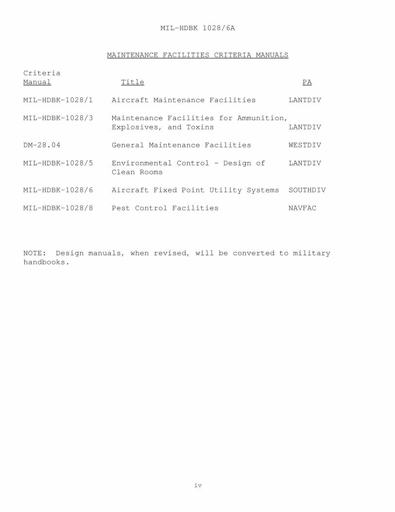
MAINTENANCE FACILITIES CRITERIA MANUALS
CriteriaManual Title PA
MIL-HDBK-1028/1 Aircraft Maintenance Facilities LANTDIV
MIL-HDBK-1028/3 Maintenance Facilities for Ammunition, Explosives, and Toxins LANTDIV
DM-28.04 General Maintenance Facilities WESTDIV
MIL-HDBK-1028/5 Environmental Control - Design of LANTDIV Clean Rooms
MIL-HDBK-1028/6 Aircraft Fixed Point Utility Systems SOUTHDIV
MIL-HDBK-1028/8 Pest Control Facilities NAVFAC
NOTE: Design manuals, when revised, will be converted to militaryhandbooks.

MIL-HDBK 1028/6A
v
AIRCRAFT FIXED POINT UTILITY SYSTEMS
CONTENTSPage
Section 1 INTRODUCTION 1.1 Scope..................................... 1 1.2 Cancellation.............................. 1
Section 2 FIXED POINT UTILITY SYSTEMS 2.1 General................................... 2 2.1.1 Planning.................................. 2 2.1.2 Aircraft Services......................... 2 2.1.2.1 Alternate 1............................... 2 2.1.2.2 Alternate 2............................... 2 2.1.3 Central Equipment Facilities.............. 3 2.1.4 Utilities Distribution.................... 3 2.1.5 Site Configuration........................ 3 2.2 Utility System Load Determinations........ 4 2.2.1 Aircraft Utility Demands.................. 4 2.2.2 System Load Diversity..................... 4 2.2.3 System Load Demands....................... 4 2.3 Starting Air System....................... 4 2.3.1 System Components......................... 8 2.3.2 Design Requirements....................... 8 2.3.3 Design Conditions......................... 8 2.4 Environmental Control System (ECS)........ 8 2.4.1 System Components......................... 8 2.4.2 Design Requirements....................... 9 2.4.3 Design Conditions......................... 9 2.5 Preconditioned Cooling Air System......... 9 2.6 Electrical System......................... 9 2.6.1 System Components......................... 9 2.6.2 Design Requirements....................... 10
Section 3 SYSTEM COMPONENT SELECTION 3.1 Standardization of Components............. 26 3.1.1 Minimum Unit Demands...................... 26 3.1.2 Maximum Unit Capacities................... 26 3.1.3 Design Methods............................ 26 3.1.4 Design Method Summaries................... 26 3.1.4.1 Selecting Starting Air Equipment.......... 26 3.1.4.2 Selecting ECS Air Equipment............... 27 3.2 Starting Air System....................... 27 3.2.1 Air Compressor and Auxiliaries............ 27 3.2.1.1 Compressor................................ 27 3.2.1.2 Intercooler............................... 34 3.2.1.3 Motor..................................... 34
MIL-HDBK 1028/6A
vi
Page 3.2.1.4 Air Intake Filter Silencer................ 34 3.2.1.5 Aftercooler............................... 34 3.2.1.6 Aftercooler (Alternate)................... 34 3.2.1.7 Oil Separator............................. 34 3.2.1.8 Refrigerated Air Dryer.................... 34 3.2.1.9 Cooling Water Assembly (for Water-Cooled
Aftercooler).............................. 34 3.2.1.10 Circulating Pumps......................... 34 3.2.1.11 Controls.................................. 34 3.2.2 Air Receiver Storage Tanks................ 34 3.2.3 Miscellaneous Equipment and Piping........ 35 3.2.3.1 Distribution System Pressure Control Valve.35 3.2.3.2 Pressure Relief Valve..................... 35 3.2.3.3 Piping.................................... 35 3.2.3.4 Miscellaneous Equipment................... 35 3.2.4 Distribution System....................... 35 3.3 Environmental Control Cooling Air System.. 35 3.3.1 Air Compressor and Auxiliaries............ 36 3.3.1.1 Compressor................................ 36 3.3.1.2 Intercoolers and Aftercooler.............. 36 3.3.1.3 Drive Motor............................... 36 3.3.1.4 Air Intake Filter-Silencer................ 36 3.3.1.5 Oil Separator............................. 36 3.3.1.6 Refrigerated Air Dryer.................... 36 3.3.1.7 Cooling Water Assembly (Evaporative Type). 36 3.3.1.8 Alternate Cooling Water Assembly.......... 36 3.3.1.9 Circulating Pumps......................... 37 3.3.1.10 Controls.................................. 37 3.3.2 Miscellaneous Equipment and Piping........ 37 3.3.3 Distribution System....................... 37 3.4 60-Hz Electrical System................... 38 3.4.1 Switchgear and Equipment.................. 38 3.4.1.1 Switchgear Assembly....................... 38 3.4.2 Distribution System....................... 38 3.4.2.1 Main Feeders.............................. 38 3.4.3 Aircraft Grounding Point Requirements..... 38 3.5 400 Hz Electrical System.................. 38
Section 4 CENTRAL FACILITIES BUILDING 4.1 General................................... 39 4.2 Building.................................. 39 4.2.1 Restrictions on the Use of Aluminum....... 39 4.2.2 Architectural Requirements................ 39 4.2.2.1 Walls..................................... 39 4.2.2.2 Roof...................................... 39 4.2.2.3 Floors.................................... 39
MIL-HDBK 1028/6A
vii
Page 4.2.2.4 Entrances................................. 40 4.2.2.5 Rooms..................................... 40 4.2.2.6 Floor Trenches............................ 40 4.2.3 Structural Requirements................... 40 4.2.3.1 Foundations............................... 40 4.2.3.2 Building Frame............................ 40 4.2.3.3 Floor Structures.......................... 40 4.2.3.4 Equipment Pads............................ 40 4.2.4 Mechanical Requirements................... 40 4.2.4.1 Plumbing System........................... 41 4.2.4.2 Heating System............................ 41 4.2.4.3 Ventilation System........................ 41 4.2.5 Electrical Requirements................... 41 4.2.5.1 Lighting.................................. 41 4.2.5.2 Communications............................ 41
Section 5 FEEDER DISTRIBUTION CENTERS 5.1 Electrical Distribution................... 42
Section 6 UNDERGROUND INSTALLATIONS 6.1 Mains and Feeders......................... 43 6.1.1 Compressed Air Piping..................... 43 6.1.2 Electrical................................ 43 6.1.2 Service Access Points..................... 43 6.2.1 Valve Boxes............................... 43
Section 7 AIRCRAFT SERVICE POINTS 7.1 Parking Apron Service Points.............. 44 7.1.1 Construction.............................. 44 7.1.2 Mechanical Equipment Components........... 44 7.1.3 Electrical Equipment Components........... 45 7.1.3.1 60 Hz Components.......................... 45 7.1.3.2 400 Hz Components......................... 46
Section 8 HANGAR SERVICE POINTS 8.1 Hangar Service Points..................... 47 8.1.1 Construction ............................. 47 8.1.2 Compressed Air Equipment Components....... 47 8.1.3 Preconditioned Air Equipment Components... 47 8.1.4 Preconditioned Air Equipment Components
(Alternate)............................... 48 8.1.5 Electrical System Components.............. 48 8.1.5.1 60 Hz Components.......................... 48 8.1.5.2 400 Hz Components......................... 49

MIL-HDBK 1028/6A
viii
PageAPPENDIX
APPENDIX A Metric Equivalent Chart........................ 50
FIGURES
Figure 1 Typical FPUS Site Plan.................... 7 2 FPUS Diversity Curve...................... 11 3 Starting Air System....................... 12 4 ECS Air System............................ 13 5 Preconditioned Cooling Air System
(Under Development)....................... 14 6 Typical One Line Diagram Central
Facilities - ECS System.................. 15 7 Typical One Line Diagram Central
Facilities - Air Start System............. 16 8 Typical Parking Apron Service Point
Electrical One-Line Diagram............... 17 9 Typical Hangar Service Point Electrical
One-Line Diagram.......................... 18 10 Feeder Distribution Center................ 19 11 FPUS Electrical Symbols................... 20 12 FPUS Electrical Symbols................... 21 13 Aircraft Service Console Mechanical
Schematic................................. 22 14 Aircraft Service Mechanical Symbols....... 23
TABLES
Table 1 Summary of Aircraft Utility Demands....... 5 2 Summary of Design Method for Quantities
and Ratings, Central Facilities EquipmentSelection, Starting Air System............ 28
3 Summary of Design Method Starting AirSystem.................................... 29
4 Summary of Design Method for Quantitiesand Ratings, Central Facilities EquipmentSelection, and Environmental Control AirSystem.................................... 30
5 Summary of Design Method, EnvironmentalControl Air System........................ 31
MIL-HDBK 1028/6A
ix
Page 6 Summary of Design Method for
Quantities and Ratings, PreconditionedAir Equipment Selection.................. 32
7 Summary of Design Method, PreconditionedAir System............................... 33
BIBLIOGRAPHY................................................. 53
REFERENCES................................................... 54
GLOSSARY..................................................... 57

MIL-HDBK 1028/6A
11
Section 1: INTRODUCTION
1.1 Scope. This handbook contains design criteria for ground powerutilities service to naval aircraft at shore activities. Utilitiesincluded are engine starting air, environmental control system compressedair, hangar preconditioned air, apron and maintenance hangar utility air,400 Hz and 60 Hz electrical power. The installations include centralfacilities supply, distribution systems and aircraft fixed point(permanently located) services.
1.2 Cancellation. This handbook, MIL-HDBK-1028/6A, dated 31 May1996, cancels and supersedes MIL-HDBK-1028/6, dated30 September 1988.
MIL-HDBK 1028/6A
22
Section 2: FIXED POINT UTILITY SYSTEMS
2.1 General. Design of the fixed point utility system (FPUS)requires determining the number and type of aircraft to be served, groundsupport requirements of the particular aircraft, expected diversity of theaircraft loads and site configuration. Resolving these variables providesthe central facilities utility demands, equipment capacities, line size androuting of the distribution system, and aircraft service pointrequirements.
2.1.1 Planning. The FPUS concept is based upon the economy ofsupply of aircraft utilities from a centralized plant of energy-efficientcomponents. Include the following considerations in FPUS planning for aparticular aircraft maintenance facility:
a) Orderly expansion of the system components to accommodateprobable future hangar bays and parking apron service points.
b) Economic feasibility of supplying adjacent or nearbyfacilities (existing or future) from the centralized supply.
c) Relocatability of ground support equipment versus FPUSinstalled equipment.
d) Probability of function relocation or base closure.
2.1.2 Aircraft Services. Fixed point systems shall supply aircraftutilities at parking apron service points and maintenance hangar servicepoints. The FPUS required are compressed air, preconditioned air forhangar aircraft, and electrical power. Two system design alternatives arefeasible. (See Table 1 for a summary of aircraft utility demands.)
2.1.2.1 Alternate 1. The air start system provides compressed air at theparking apron service points. Aircraft cooling is provided by mobileground carts. The selection of the air start system or environmentalcontrol system (ECS) system is based upon system requirements and economicfactors. Factors affecting the system selection include central plant andutility distribution construction costs, local environmental conditions,and local utility rate structures. Manpower requirements, spacelimitations, system dependability, and air quality permits to operate fuelfired yellow gear equipment outdoors must be considered in addition toeconomic analysis. The air start system will generally have the lowestinitial cost and shortest payback period while using the least energy ofany current design option.
2.1.2.2 Alternate 2. The ECS, provides compressed air for enginestarting air and ECS compressed air at the parking apron service pointsfrom a central source. The ECS will generally have the lowest operating
MIL-HDBK 1028/6A
33
and maintenance costs, resulting in the highest overall life-cycle costsavings. The ECS system also has inherent operational advantages byrequiring fewer operating personnel and minimizing the need for groundsupport equipment. The ECS requires no starting air recovery period. Dedicated and separate panels for the electrical and mechanical servicesshall be provided. For maintenance hangar service points, provideelectrical and mechanical services as shown in Figures 9, 10, 11, and 12 inthe later sections of this handbook. Separate dedicated panels formechanical and electrical services shall be provided.
2.1.3 Central Equipment Facilities. The central facilities areashall provide the equipment building and yard area for compressed airstorage tanks and substation type transformers, and switchgear for mainelectrical service. The building shall accommodate the air compressors andauxiliary equipment, electrical service, and distribution apparatus. Theequipment for preconditioned air supply to hangar aircraft shall be locatedwithin a hangar equipment room, a penthouse of the shop area or a separatestructure. Refer to MIL-HDBK-1004/5, 400-Hertz Medium-VoltageConversion/Distribution and Low-Voltage Utilization Systems for additionaldetails.
2.1.4 Utilities Distribution. The underground mains and feedersshall provide for the utilities distribution to the maintenance hangarservice points and parking apron service points. The compressed air linesand electrical conduits shall be routed in the same trench. The accessmanholes shall be provided outside the paved areas. For cable-pullingmanholes, refer to MIL-HDBK-1004/2, Power Distribution Systems.
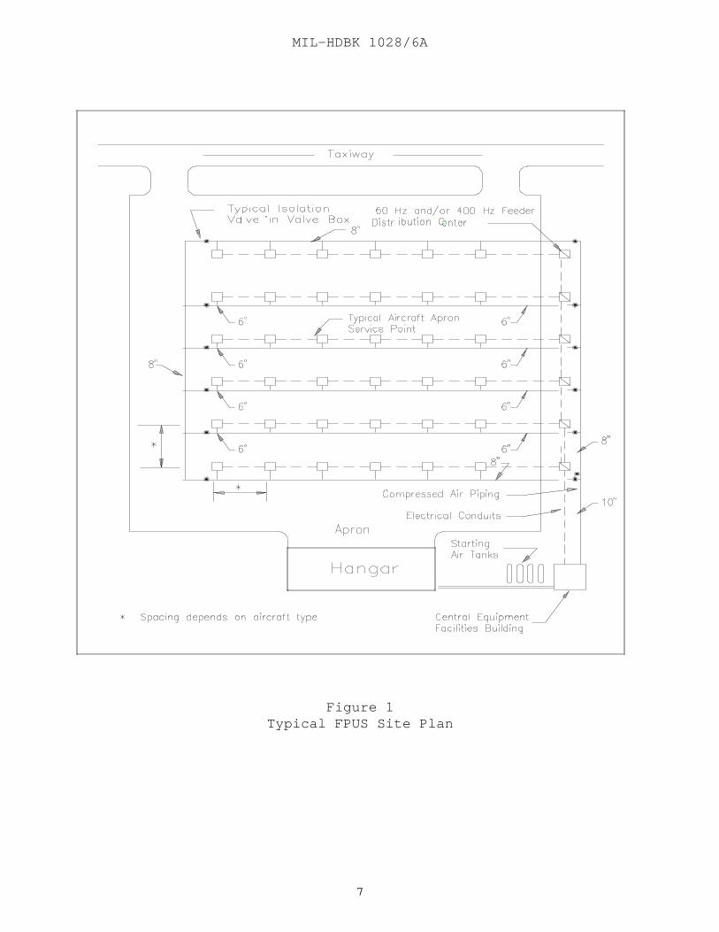
2.1.5 Site Configuration. The layout of FPUS shall be subject tothe correlated siting of maintenance hangars, parking apron space andtaxiways. For the relationship of hangars to aircraft parking areas andtaxiways, refer to NAVFAC DM-21 series, Airfield Pavement Design. Theparking apron layout is prescribed in NAVFAC P-80, Facility Planning ForNavy and Marine Corps Shore Installations. For a typical FPUS layout toserve a predescribed hangar and parking apron complex see Figure 1. Thefollowing criteria apply:
a) The central equipment facility shall be located as near thehangar as practical at a location offering the most direct access to theparking apron. Minimize the length of the underground mains to the parkingapron.
b) Locate the section of underground mains between the centralfacilities and the first transition point outside the apron and taxiwaypavements.
c) The underground compressed air distribution piping should bearranged with loops to equalize distribution line pressure throughout.

MIL-HDBK 1028/6A
44
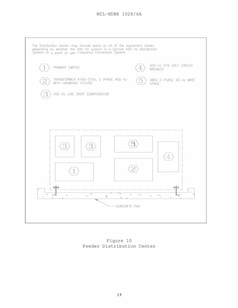
d) A feeder distribution center consists of pad-mountedequipment located off the apron as close as practical to the service pointsto minimize aircraft service voltage drop. In some cases, however, forsite reasons feeder distribution centers for apron service points may belocated in the hangar. Refer to MIL-HDBK-1004/5 for sample voltage dropcalculations. See Tables 6 and 7 of MIL-HDBK-1004/5 for maximum systemdistances. See Figure 10 for additional details.
2.2 Utility System Load Determinations. The total number and type ofaircraft plus the demands of other ground support activities to be suppliedby the fixed point facilities will determine load requirements for theutility system.
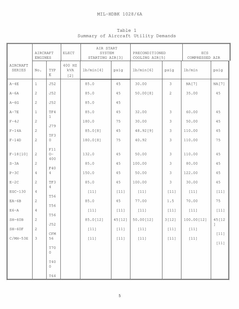
2.2.1 Aircraft Utility Demands. The utility demands required forthe support of various aircraft are itemized in Table 1. The followingaircraft unit demands shall be used as the minimum FPUS design criteria:
2.2.2 System Load Diversity. The system load diversity shall bedetermined by obtaining the system load diversity factor from Figure 2.Divide the diversity factor into the total number of aircraft underconsideration to determine the number of aircraft expected to exert asimultaneous demand.
2.2.3 System Load Demands. The system load demands shall bedetermined by multiplying the aircraft unit demand by the expectedsimultaneous demand for the portion of the system under consideration. Refer to par. 2.2.1 for aircraft minimum unit demand criteria.
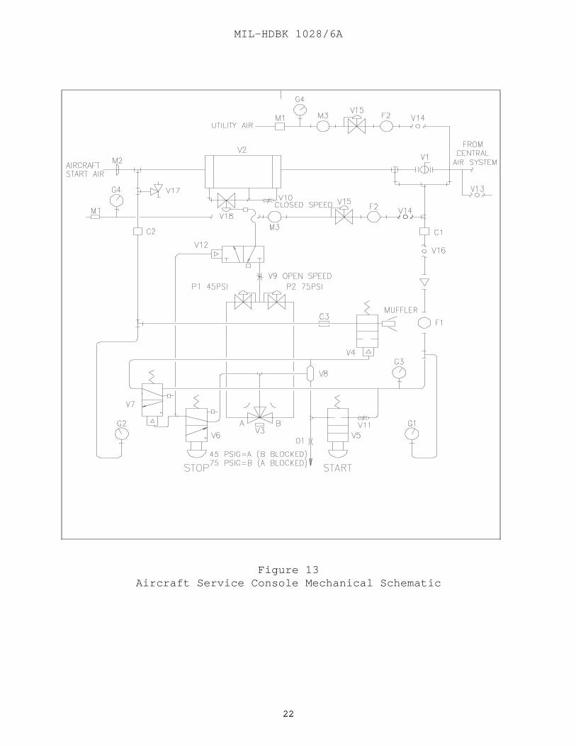
2.3 Starting Air System. The starting air system shall provide onlycompressed air for aircraft engine starting and for pneumatic tooloperation at parking apron service islands and maintenance hangar servicepoints. The system design shall comply with standards specified in NAVFACDM-3.05, Compressed Air and Vacuum Systems. See Figures 13 and 14 foraircraft service console mechanical schematic information.
MIL-HDBK 1028/6A
55
Table 1Summary of Aircraft Utility Demands
AIRCRAFTENGINES
ELECT AIR START
SYSTEMSTARTING AIR[3]
PRECONDITIONEDCOOLING AIR[5]
ECS COMPRESSED AIR
AIRCRAFT SERIES No. TYP
E
400 HZkVA
[2]
lb/min[4] psig lb/min[6] psig lb/min psig
A-4E
A-6A
A-6G
A-7E
F-4J
F-14A
F-14D
F-18[10]
S-3A
P-3C
E-2C
EGC-130
EA-6B
E6-A
SH-60B
SH-60F
C/MH-53E
1
2
2
1
2
2
2
2
2
4
2
4
2
4
2
2
3
J52
J52
J52
TF41
J79
TF30
F11O-400
F404
TF34
T56
T56
T56
J52
CFM56
T700
T400
T64
85.0
85.0
85.0
85.0
180.0
85.0[8]
180.0[8]
132.0
85.0
150.0
85.0
[11]
85.0
[11]
85.0[12]
[11]
[11]
45
45
45
45
75
45
75
45
45
45
45
[11]
45
[11]
45[12]
[11]
[11]
30.00
50.00[8]
32.00
30.00
48.92[9]
40.92
50.00
100.00
50.00
100.00
[11]
77.00
[11]
50.00[12]
[11]
[11]
3
2
3
3
3
3
3
3
3
3
[11]
1.5
[11]
3[12]
[11]
[11]
NA[7]
35.00
60.00
50.00
110.00
110.00
110.00
80.00
122.00
30.00
[11]
70.00
[11]
100.00[12]
[11]
[11]
NA[7]
45
45
45
45
75
45
45
45
45
[11]
75
[11]
45[12]
[11]
[11]
MIL-HDBK 1028/6A
66
Table 1 (Continued)Summary of Aircraft Utility Demands
NOTES:
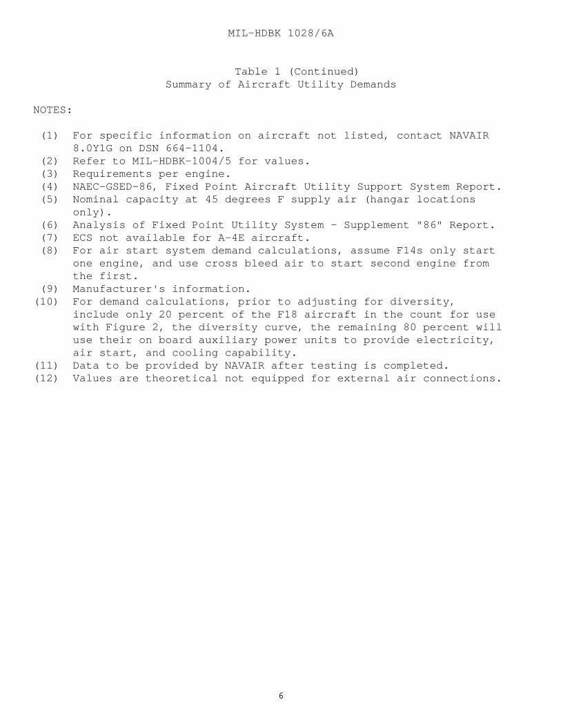
(1) For specific information on aircraft not listed, contact NAVAIR 8.0Y1G on DSN 664-1104. (2) Refer to MIL-HDBK-1004/5 for values. (3) Requirements per engine. (4) NAEC-GSED-86, Fixed Point Aircraft Utility Support System Report. (5) Nominal capacity at 45 degrees F supply air (hangar locations only). (6) Analysis of Fixed Point Utility System - Supplement "86" Report. (7) ECS not available for A-4E aircraft. (8) For air start system demand calculations, assume F14s only start one engine, and use cross bleed air to start second engine from the first. (9) Manufacturer's information.(10) For demand calculations, prior to adjusting for diversity, include only 20 percent of the F18 aircraft in the count for use with Figure 2, the diversity curve, the remaining 80 percent will use their on board auxiliary power units to provide electricity, air start, and cooling capability.(11) Data to be provided by NAVAIR after testing is completed.(12) Values are theoretical not equipped for external air connections.
MIL-HDBK 1028/6A
77
Figure 1Typical FPUS Site Plan
MIL-HDBK 1028/6A
88
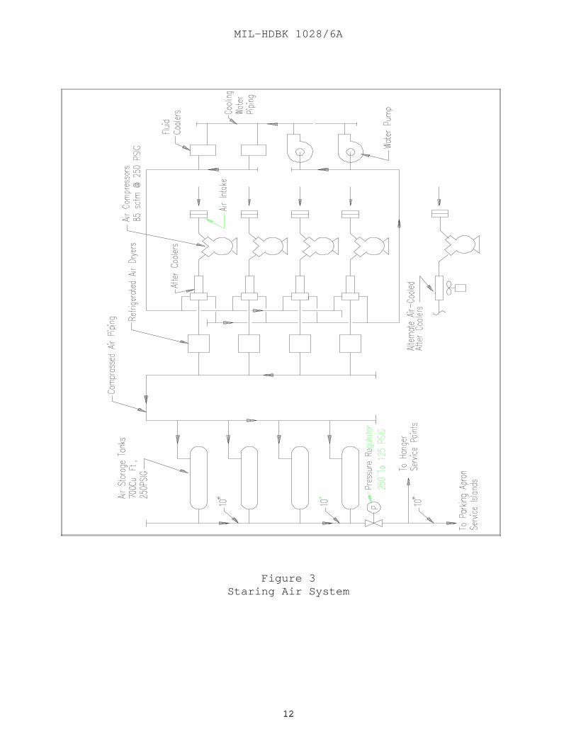
2.3.1 System Components. A schematic diagram of the starting airsystem is shown in Figure 3. The basic components of the system are:
a) Electric motor-driven, reciprocating-type air compressors,
b) Air dryers,
c) Compressor cooling system,
d) Compressor and compressed air system controls,
e) Receiver storage tanks,
f) Underground distribution system, and
g) Aircraft hangar and parking apron service point facilities.
2.3.2 Design Requirements. A broad range of starting airrequirements exists because of differences in aircraft types andfunctions of the squadron or group. The starting air system shall have aminimum compressor size and receiver tank storage capacity to supply airfor the starting (in 2 minutes) 12 of a full complement of 36 two-engineaircraft with a 2-hour recovery period. Section 3 relates this criteriarequirement to designs for less than a full complement of aircraft.
2.3.3 Design Conditions. The equipment ratings shall be based onstandard ambient conditions of 14.67 psia (101.13 kPa) atmospheric pressureand 70 degrees F (21 degrees C) dry bulb temperature. The system shall bedesigned to supply air at the parking apron service island in the quantityrequired measured at 45 psig (310.23 kPa) or75 psig (517.05 kPa).
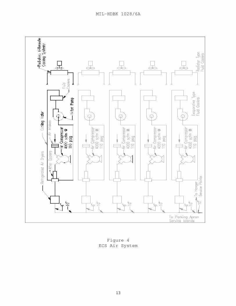
2.4 Environmental Control System. The function of the ECS is toprovide compressed air for aircraft engine starting, ECS compressed air,and pneumatic tool operation at parking apron service islands andmaintenance hangar service points. The ECS uses compressed air to operatethe aircraft air cycle refrigeration machine which provides cockpit andcabin pressurization comfort conditioning, avionics and radar cooling, andother heating and cooling tasks. The system design shall comply withpiping and installation standards specified in NAVFACDM-3.05.
2.4.1 System Components. A schematic diagram of the environmentalcontrols compressed air system is shown in Figure 4. Basic components ofthe system are:
MIL-HDBK 1028/6A
99
a) Electric motor-driven centrifugal or rotary-screwtype compressors,
b) Air dryers,c) Compressor cooling system,
d) Compressor and compressed air system controls,
e) Underground distribution system, and
f) Aircraft hangar and parking apron service point facilities.
2.4.2 Design Requirements. A broad range of starting and coolingair requirements exists because of differences in aircraft types andoperational function of the squadron or group. The ECS shall have aminimum compressor size to supply air for the simultaneous starting of 12of a typical full complement of 36 two-engine aircraft or the cooling of 3of a full complement of 36 aircraft. Because the ECS compressed air flowrequirement is larger and is of longer duration than the starting airrequirement, the ECS compressed air requirement is used to determinecompressor size. With this requirement, all 12 aircraft can be started in3 minutes with no recovery time required.
2.4.3 Design Conditions. For design conditions refer to par. 2.3.3.
2.5 Preconditioned Cooling Air System. Note: A study commissionedby NAVFACENGCOM Criteria Office is underway relative to providingpreconditioned cooling air. Results will be incorporated into thishandbook when completed. See Figure 5.
2.6 Electrical System. The electrical system provides the main powersupply and distribution for FPUS central equipment operations and centralfacilities building services, and distributes 400 Hz and 60 Hz power toparking apron service points and hangar service points. Provide load-center type unit substation to supply FPUS facility power from the navalair station primary distribution system. System design shall comply withelectrical installation standards specified inMIL-HDBK-1004/1, Electrical Engineering, Preliminary Design Considerations,MIL-HDBK-1004/2, MIL-HDBK-1004/3, Switchgear and Relaying, MIL-HDBK-1004/4,Electrical Utilization Systems,MIL-HDBK-1004/5, and MIL-HDBK-1004/6, Lightning Protection, and NationalFire Protection Association (NFPA) 70, National Electrical Code, andAmerican National Standards Institute (ANSI) C2, National Electrical SafetyCode.
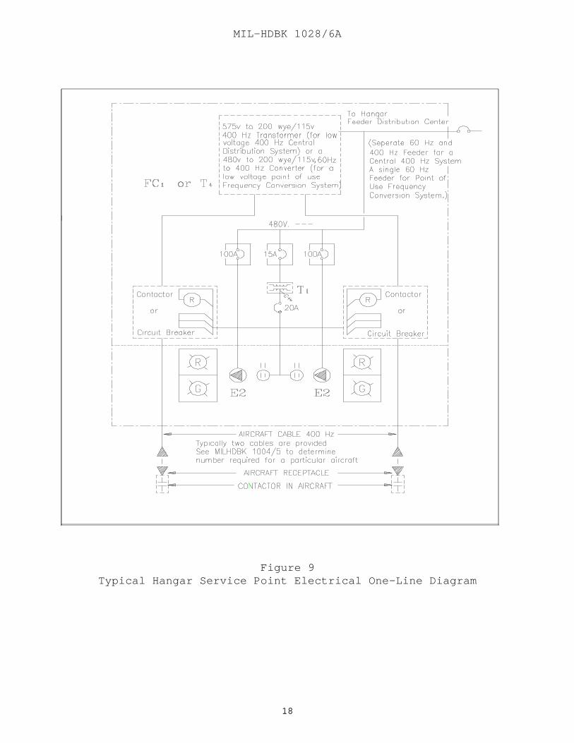
2.6.1 System Components. Schematic diagrams of typical electricalsystems for the ECS and air start system are shown in Figures 6, 7, 8and 9. The basic components of the system are:

MIL-HDBK 1028/6A
1010
a) Medium and low-voltage switchgear with main breakerand metering;
b) Motor control center;
c) 400 Hz, solid state converters ( NAVFACENGCOM policy is toprovide solid state frequency converters. Some motor-generator frequencyconverter 400 Hz systems exist, repairs and additions to these systemsshall adhere to criteria contained herein and in MIL-HDBK-1004/5);
d) Transformers and circuit breaker distribution panels;
e) Underground distribution system with manholes andhandholes as required;
f) Electrical feeder distribution (see Figures 6, 7, 8, 9,and 10);
g) Aircraft hangar service point and parking apron service pointfacilities ( refer to MIL-HDBK-1004/5).
2.6.2 Design Requirements. A broad range of electricalrequirements exists because of differences in aircraft types andoperational function of squadron or group. The electrical demand for boththe 60 Hz and 400 Hz shall be based on serving 12 of a full complement of36 aircraft. The resulting demand is proportioned between parking apronservice points and hangar service points with a ratio of 2 to 1respectively. Section 3 relates this criteria requirement to designs forless than full complement of aircraft.

MIL-HDBK 1028/6A
1111
Figure 2FPUS Diversity Curve
MIL-HDBK 1028/6A
1212
Figure 3Staring Air System
MIL-HDBK 1028/6A
1313
Figure 4ECS Air System
MIL-HDBK 1028/6A
1414
(NOTE: A STUDY COMMISSIONED BY NAVFAC CRITERIA OFFICE IS UNDERWAY RELATIVETO PRECONDITIONED COOLING AIR. RESULTS WILL BE INCORPORATED INTO THISHANDBOOK WHEN COMPLETED.)
Figure 5Preconditioned Cooling Air System

MIL-HDBK 1028/6A
1515
Figure 6Typical One Line Diagram Central Facilities - ECS System

MIL-HDBK 1028/6A
1616
Figure 7Typical One Line Diagram Central Facilities Air Start System

MIL-HDBK 1028/6A
1717
Figure 8Typical Parking Apron Service Point Electrical One-Line Diagram
MIL-HDBK 1028/6A
1818
Figure 9Typical Hangar Service Point Electrical One-Line Diagram
MIL-HDBK 1028/6A
1919
Figure 10Feeder Distribution Center

MIL-HDBK 1028/6A
2020
Figure 11FPUS Electrical Symbols
MIL-HDBK 1028/6A
2121
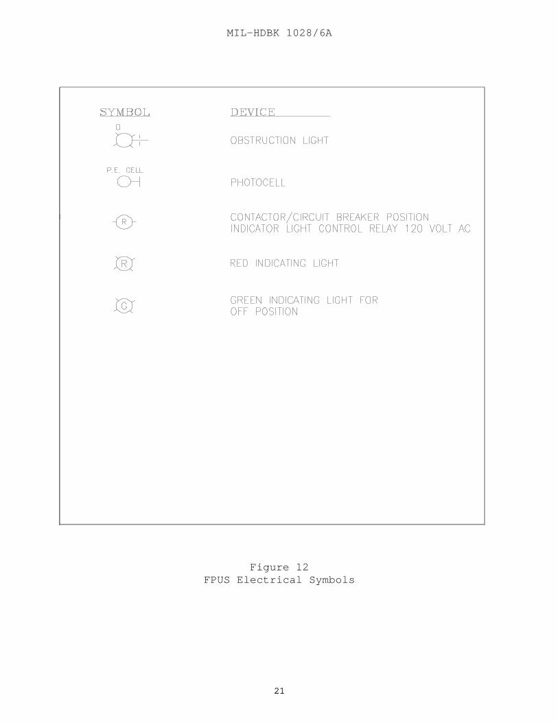
Figure 12FPUS Electrical Symbols
MIL-HDBK 1028/6A
2222
Figure 13Aircraft Service Console Mechanical Schematic
MIL-HDBK 1028/6A
2323
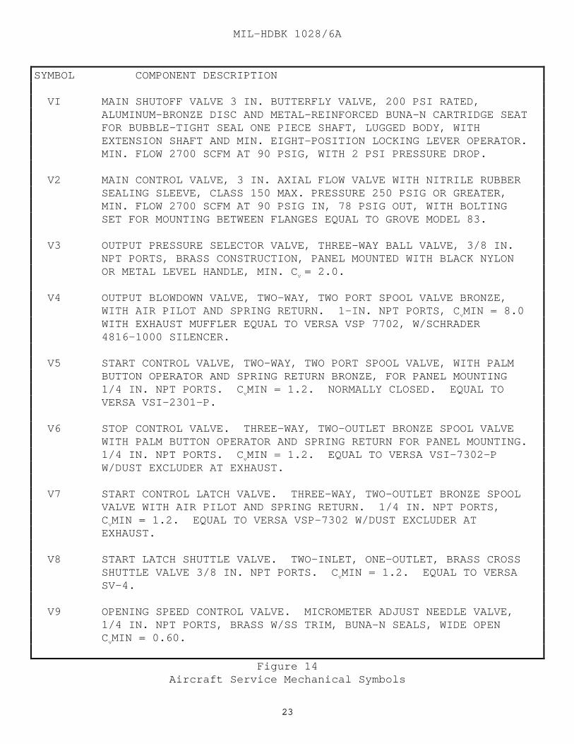
SYMBOL COMPONENT DESCRIPTION
VI MAIN SHUTOFF VALVE 3 IN. BUTTERFLY VALVE, 200 PSI RATED,ALUMINUM-BRONZE DISC AND METAL-REINFORCED BUNA-N CARTRIDGE SEATFOR BUBBLE-TIGHT SEAL ONE PIECE SHAFT, LUGGED BODY, WITHEXTENSION SHAFT AND MIN. EIGHT-POSITION LOCKING LEVER OPERATOR.MIN. FLOW 2700 SCFM AT 90 PSIG, WITH 2 PSI PRESSURE DROP.
V2 MAIN CONTROL VALVE, 3 IN. AXIAL FLOW VALVE WITH NITRILE RUBBERSEALING SLEEVE, CLASS 150 MAX. PRESSURE 250 PSIG OR GREATER,MIN. FLOW 2700 SCFM AT 90 PSIG IN, 78 PSIG OUT, WITH BOLTINGSET FOR MOUNTING BETWEEN FLANGES EQUAL TO GROVE MODEL 83.
V3 OUTPUT PRESSURE SELECTOR VALVE, THREE-WAY BALL VALVE, 3/8 IN.NPT PORTS, BRASS CONSTRUCTION, PANEL MOUNTED WITH BLACK NYLONOR METAL LEVEL HANDLE, MIN. C v = 2.0.
V4 OUTPUT BLOWDOWN VALVE, TWO-WAY, TWO PORT SPOOL VALVE BRONZE,WITH AIR PILOT AND SPRING RETURN. 1-IN. NPT PORTS, C vMIN = 8.0WITH EXHAUST MUFFLER EQUAL TO VERSA VSP 7702, W/SCHRADER4816-1000 SILENCER.
V5 START CONTROL VALVE, TWO-WAY, TWO PORT SPOOL VALVE, WITH PALMBUTTON OPERATOR AND SPRING RETURN BRONZE, FOR PANEL MOUNTING1/4 IN. NPT PORTS. C vMIN = 1.2. NORMALLY CLOSED. EQUAL TOVERSA VSI-2301-P.
V6 STOP CONTROL VALVE. THREE-WAY, TWO-OUTLET BRONZE SPOOL VALVEWITH PALM BUTTON OPERATOR AND SPRING RETURN FOR PANEL MOUNTING.1/4 IN. NPT PORTS. C vMIN = 1.2. EQUAL TO VERSA VSI-7302-PW/DUST EXCLUDER AT EXHAUST.
V7 START CONTROL LATCH VALVE. THREE-WAY, TWO-OUTLET BRONZE SPOOLVALVE WITH AIR PILOT AND SPRING RETURN. 1/4 IN. NPT PORTS,CvMIN = 1.2. EQUAL TO VERSA VSP-7302 W/DUST EXCLUDER ATEXHAUST.
V8 START LATCH SHUTTLE VALVE. TWO-INLET, ONE-OUTLET, BRASS CROSSSHUTTLE VALVE 3/8 IN. NPT PORTS. C vMIN = 1.2. EQUAL TO VERSASV-4.
V9 OPENING SPEED CONTROL VALVE. MICROMETER ADJUST NEEDLE VALVE,1/4 IN. NPT PORTS, BRASS W/SS TRIM, BUNA-N SEALS, WIDE OPENCvMIN = 0.60.
Figure 14Aircraft Service Mechanical Symbols

MIL-HDBK 1028/6A
2424
SYMBOL COMPONENT DESCRIPTION
V10 CLOSING SPEED CONTROL VALVE. SIMILAR TO V9. 3/8 IN. NPTPORTS. MIN C v = 0.60.
V11 START-LOCKOUT PRESSURE ADJUSTMENT VALVE. SIMILAR TO V9,1/4 IN. NPT PORTS. C vMIN = 0.30.
V12 PRIMARY REGULATOR ISOLATION AND EXHAUST VALVE. THREE-WAY,TWO-OUTLET BRONZE SPOOL VALVE, WITH AIR PILOT AND SPRINGRETURN. 1/4 IN. NPT PORTS. C vMIN = 1.2. EQUAL TO VERSAVSP-7302. W/DUST EXCLUDER AT EXHAUST.
V13 BLOW-OFF VALVE. 1/2 IN. BALL VALVE W/CAP AND CHAIN.
V14 UTILITY AIR SHUTOFF VALVE. 1/2 IN. NPT BRONZE BALL VALVE,WITH LEVER HANDLE. WIDE OPEN C v = 9.0.
V15 UTILITY AIR PRESSURE REGULATOR. 100 SCFM AT 130 PSIG INLET.5 PSI PRESSURE DROP. SPRING-LOADED DIAPHRAGM TYPE, ADJUSTABLE,NON-BLEED RELIEVING.
V16 CONTROL TRAY SUPPLY AIR ISOLATION VALVE. SAME AS V14.ONLY 3/4 IN.
V17 OUTPUT LINE SURGE RELIEF VALVE. SET 90 PSIG. DISCHARGE 1200SCFM TO ATMOSPHERE AT 100 PSIG. 2 IN. NPT.
V18 PRIMARY PRESSURE REGULATOR (FOR V2), AIR LOADED, 1 IN. CASTIRON BODY, NEOPRENE DIAPHRAGM, BUNA-N VALVE DISC. HIGHPRESSURE VERSION 1/4 IN. ORIFICE.
F1 UTILITY AIR FILTER. 100 SCFM AT 125 PSIG, WITH 5 PSI INITIALPRESSURE DROP, METAL BOWL. AUTO DRAINER, 1/2 IN. NPT PORTS.5 MICRON ELEMENT. 3/4 IN. NPT.
F2 CONTROL AIR FILTER, 100 SCFM AT 100 PSIG WITH 5 PSI INITIALPRESSURE DROP, METAL BOWL, AUTO DRAINER. 1/2 IN. NPT PORTS.5 MICRON ELEMENT.
C1 CONTROL TRAY SUPPLY AIR CONNECTOR. GALVANIZED MALLEABLE IRONPIPE UNION. 150 POUND. BRASS SEAT, NUT TYPE WITH BUNA-NO-RING.
C2 CONTROL TRAY SENSING/BLOWDOWN CONNECTOR. 1 IN. NPT.
Figure 14 (Continued)Aircraft Service Mechanical Symbols
MIL-HDBK 1028/6A
2525
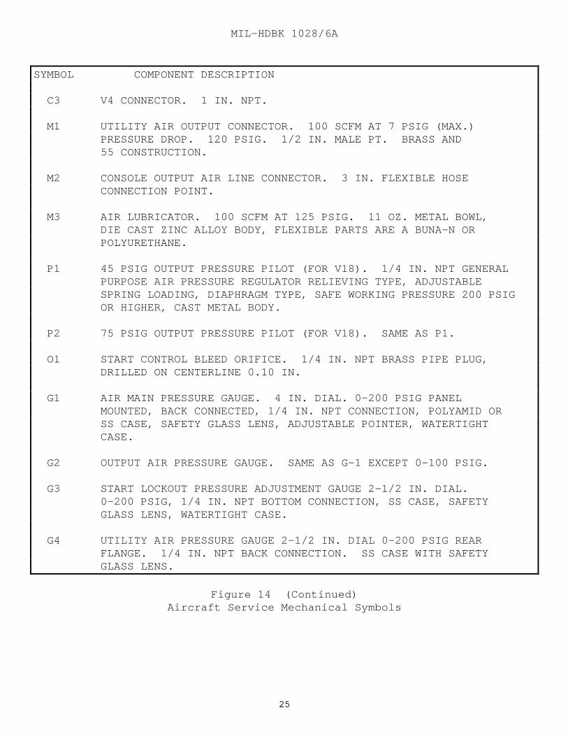
SYMBOL COMPONENT DESCRIPTION
C3 V4 CONNECTOR. 1 IN. NPT.
M1 UTILITY AIR OUTPUT CONNECTOR. 100 SCFM AT 7 PSIG (MAX.)PRESSURE DROP. 120 PSIG. 1/2 IN. MALE PT. BRASS AND55 CONSTRUCTION.
M2 CONSOLE OUTPUT AIR LINE CONNECTOR. 3 IN. FLEXIBLE HOSECONNECTION POINT.
M3 AIR LUBRICATOR. 100 SCFM AT 125 PSIG. 11 OZ. METAL BOWL,DIE CAST ZINC ALLOY BODY, FLEXIBLE PARTS ARE A BUNA-N ORPOLYURETHANE.
P1 45 PSIG OUTPUT PRESSURE PILOT (FOR V18). 1/4 IN. NPT GENERALPURPOSE AIR PRESSURE REGULATOR RELIEVING TYPE, ADJUSTABLESPRING LOADING, DIAPHRAGM TYPE, SAFE WORKING PRESSURE 200 PSIGOR HIGHER, CAST METAL BODY.
P2 75 PSIG OUTPUT PRESSURE PILOT (FOR V18). SAME AS P1.
O1 START CONTROL BLEED ORIFICE. 1/4 IN. NPT BRASS PIPE PLUG,DRILLED ON CENTERLINE 0.10 IN.
G1 AIR MAIN PRESSURE GAUGE. 4 IN. DIAL. 0-200 PSIG PANELMOUNTED, BACK CONNECTED, 1/4 IN. NPT CONNECTION, POLYAMID ORSS CASE, SAFETY GLASS LENS, ADJUSTABLE POINTER, WATERTIGHTCASE.
G2 OUTPUT AIR PRESSURE GAUGE. SAME AS G-1 EXCEPT 0-100 PSIG.
G3 START LOCKOUT PRESSURE ADJUSTMENT GAUGE 2-1/2 IN. DIAL.0-200 PSIG, 1/4 IN. NPT BOTTOM CONNECTION, SS CASE, SAFETYGLASS LENS, WATERTIGHT CASE.
G4 UTILITY AIR PRESSURE GAUGE 2-1/2 IN. DIAL 0-200 PSIG REARFLANGE. 1/4 IN. NPT BACK CONNECTION. SS CASE WITH SAFETYGLASS LENS.
Figure 14 (Continued)Aircraft Service Mechanical Symbols
MIL-HDBK 1028/6A
2626
Section 3: SYSTEM COMPONENT SELECTION
3.1 Standardization of Components. Standardization of FPUScomponents requires that central facilities equipment and main distributioncomponents be selected for energy-efficient operation and according to thebasic design methods defined in pars. 3.1.1 through 3.1.4.
3.1.1 Minimum Unit Demands. The minimum aircraft unit demands foraircraft ground support are as detailed in par. 2.2.1.
3.1.2 Maximum Unit Capacities. The maximum unit capacity ofcentral facilities equipment shall be based upon the number of groundsupport equipment (GSE) available to serve as standby. Generally, thatavailability will be approximately one-fourth of the central facilitiestotal demand as determined in Section 2.
3.1.3 Design Methods. The preceding requirements of aircraft unitdemands, diversity of loads, minimum unit demand, and maximum capacities ofcentral facilities equipment, when properly coordinated, formulate thedesign method. The design method is formulated on the basis of therequirements of carrier-type aircraft. The number of general purpose orspecial mission aircraft assigned to a particular facility isunpredictable. For such applications, determine the total utility demandby dividing the product of the aircraft unit demand and the number ofaircraft by the diversity factor.
3.1.4 Design Method Summaries. Tables 2 through 7 summarize thedesign method for the determination of the quantity and ratings of thecentral facilities equipment. Calculations are based on air at standardconditions of 14.7 psia (101.35 kPa), 68 degrees F (20 degrees C), 36percent relative humidity.
3.1.4.1 Selecting Starting Air Equipment. Table 2 summarizes the methodfor selecting starting air equipment. Table 3 presents an example for astarting air system based upon the following conditions:
a) Compressor discharge pressure = 250 psig (1723.5 kPa)
b) Pressure drop, compressor-to-receiver = 10 psig (68.94 kPa)
c) Pressure drop, PRV to service point = 20 psig (137.88 kPa)
d) Pipeline volume = 2300 cu. ft. (64.4 cu. m) at an averagepressure of 115 psig (792.81 kPa)

MIL-HDBK 1028/6A
2727
The above information is necessary to determine the allowablesystem pressure drops. The minimum pressure required in the receivers forthis example is 65 psig (448.1 kPa) which equals 45 psig (310.23 kPa)service point pressure plus 20 psig pipeline pressure drop. The maximumreceiver pressure is 240 psig (1,654.56 kPa) since 10 psig is lost in thepiping system between the compressor discharge and the receiver inlet.
3.1.4.2 Selecting ECS Air Equipment. Table 4 is a summary of the methodfor selecting ECS air equipment.
a) An example of an ECS air system is provided in Table 5, basedupon the following conditions:
(1) Compressor discharge pressure = 110 psig (758.34 kPa)
(2) Pressure drop, compressor to service point = 10 psig(68.94 kPa) at minimum load and not exceeding 65 psig (448.11 kPa) atmaximum load.
b) A summary of the method for selecting preconditioned airequipment is provided in Table 6. An example for a preconditioned airsystem is provided in Table 7, based upon the following conditions:
(1) Ambient air at 100 degrees F (38 degrees C) dry bulb,110 grains/lb moisture
(2) System pressure drop = 0.5 psig (3.447 kPa)
(3) Temperature gain, service point to aircraft =2 degrees F (16.6 degrees C) dry bulb
(4) Supply fan of 44 brake horsepower, 90 percent efficient,124,500 Btuh (36,478.5 W) heat gain each.
3.2 Starting Air System. The starting air systems shall comply withthe requirements of NAVFAC DM-3.05. A compressor and auxiliary equipmentshall be provided as a coordinated assembly by the air compressormanufacturer requiring a maximum of 30 bhp per 100 cfm (2.8 cu. m/min) ofintake air. Compressors shall operate satisfactorily, individually, or inparallel with any combination of other units. A compressor and compressedair system controls shall be provided to provide fully automatic operation.
3.2.1 Air Compressor and Auxiliaries. Air compressors and theauxiliary assembly shall be provided as defined in pars. 3.2.1.1. through3.2.1.11.
3.2.1.1 Compressor. Two-stage, vertical or horizontal, cross-head type,single or double-acting, water-cooled, oil-free style shall be provided.

MIL-HDBK 1028/6A
2828
Table 2
Summary of Design Method for Quantities and Ratings, CentralFacilities Equipment Selection, Starting Air System
BASIS OF DETERMINATION FOR RECOMMENDED UNIT CAPACITYAND NUMBER OF EQUIPMENT UNITS:
Step Description 1. Number and type of aircraft:
2. Aircraft service requirements: Starting air = lb/min psig (per engine) Electrical = kVA, Hz
3. Aircraft to be served simultaneously: Total number of aircraft = aircraft to be served Diversity factor
4. Number and location of services to be provided: Starting air = number, flight line Electrical = number, hangar Electrical = number, flight line
5. System capacity:
Starting air storage capacity: Number aircraft x lb/min x min x (no. engines)** = lb Storage vol., std. cu. ft. (scf) = lb x specific volume Pipeline equiv. vol.=pipe vol. x allowable pressure drop atmospheric pressure Receiver capacity=(stor.vol.-pipe equiv.)x atmos. press. allowable pressure drop Starting air compressor capacity: Storage, volume, scf = scfm Recovery time, minutes Electrical capacity: Number aircraft x kVA/aircraft = kVA
6. Equipment unit size: Total system capacity (Item 5) = unit capacity *Number of units
7. Select manufacturer's standard size that meets or exceeds unit capacity calculated
* Recommended number of units is 4 (selected for 25 percent of total system capacity).** Refer to Table 1.

MIL-HDBK 1028/6A
2929
Table 3Example of Design Method Starting Air System
RECOMMENDED UNIT CAPACITYStep Description
1. Number and type of aircraft: 36 F-14 aircraft
2. Aircraft requirements: Starting air = 85 lb/min 45 psig 2 engines *Electrical = 20.0 kVA, 400 Hz
3. Aircraft to be served simultaneously: 36 aircraft = 12 aircraft 3.0 diversity factor
4. Number and location of services to be provided: Starting air = 12 on flight line Electrical = 4 in hangar Electrical = 8 on flight line
5. System capacity: Starting air storage capacity: 12 aircraft x 85 lb/min x 1 min x 2 engs = 2040 lb 2040 lb x 13.33 scf/lb = 27,192 scf (total) 2300 cf x 115-65 psig = 7823 scf (pipeline) 14.7 psi 27,192-7823 scf x 14.7 psi = 970 scf (receiver) 240-65 psig Starting air compressor capacity: 27,192 scf = 230 scfm 120 min Electrical: 12 aircraft x 20 kVA/aircraft = 240 kVA
6. Equipment unit size: Starting air: (receiver capacity) 970 scf = 245 scf 4 Starting air: (compressor capacity) 230 scfm = 57 scfm 4 7. Select 4 compressors at 55 scfm 250 psig each and 4 nominal 250 scf storage tanks.
*Includes Spare Capacity - see Table 1.

MIL-HDBK 1028/6A
3030
Table 4Summary of Design Method for Quantities and Ratings, Central
Facilities Equipment Selection, and Environmental Control Air System
BASIS OF DETERMINATION FOR RECOMMENDED UNITCAPACITY AND NUMBER OF EQUIPMENT UNITS:
Step Description 1. Number and type of aircraft:
2. Aircraft service requirements: ECS air = lb/min psig (per engine) Electrical = kVA, Hz
3. Aircraft to be served simultaneously: Total number of aircraft = aircraft to be served Diversity factor
4. Number and location of services to be provided: Preconditioned air = number, hangar ECS air = number, flight line (aircraft served less number, hangar) Electrical = number, hangar Electrical = number, flight line
5. System capacity:
ECS air compressor capacity: Number, flight line x lb/min x specific vol. scf/min
Electrical: Number aircraft x kVA/aircraft = kVA
6. Equipment unit size: Total system capacity (Item 5) = unit capacity *Number of unit modules Select manufacturer's standard size that meets or exceeds unit capacity calculated.
* Recommended number of unit modules is four. (For large capacity systems,the preferred compressor selection is three units at 25 percent systemtotal with the fourth module divided into two units at 12.5 percent each.)

MIL-HDBK 1028/6A
3131
Table 5Example of Design Method, Environmental Control Air System
RECOMMENDED UNIT CAPACITY
Step Description
1. Number and type of aircraft: 36 F-14 aircraft
2. Aircraft service requirements: ECS air = 100 lb/min 45 psig Electrical = 20.0 kVA, 400 Hz
3. Aircraft to be served simultaneously: 36 aircraft = 12 aircraft 3.0 diversity factor
4. Number and location of services to be provided: Preconditioned air = 4 in hangar ECS air = 12 on flight line Electrical = 8 on flight line Electrical = 4 in hangar
5. System capacity:
ECS air compressor capacity: 12 aircraft x 100 lb/min x 13.33 scf/lb = 16,000 scfm
Electrical: 12 aircraft x 20 kVA = 240 kVA total demand
6. Equipment unit size: ECS air: (compressor capacity) 16,000 scfm = 4000 scfm 4
7. Select three compressors at 4000 scfm and two at 2000 scfm, all at 110 psig discharge pressure.

MIL-HDBK 1028/6A
3232
Table 6Summary of Design Method for Quantities and Ratings, Preconditioned
Air Equipment Selection
NOTE: A STUDY COMMISSIONED BY NAVFACENGCOM CRITERIA OFFICE ISUNDERWAY RELATIVE TO PRECONDITIONED COOLING AIR. RESULTS WILLBE INCORPORATED INTO THIS HANDBOOK WHEN COMPLETED.
MIL-HDBK 1028/6A
3333
Table 7Example of Design Method, Preconditioned Air System
NOTE: A STUDY COMMISSIONED BY NAVFACENGCOM CRITERIA OFFICE ISUNDERWAY RELATIVE TO PRECONDITIONED COOLING AIR. RESULTS WILLBE INCORPORATED INTO THIS HANDBOOK WHEN COMPLETED.
MIL-HDBK 1028/6A
3434
3.2.1.2 Intercooler. Air-cooled finned-tube coil or water-cooled type,directly or remotely attached to compressor.
3.2.1.3 Motor. V-belt drive, open-drip proof, squirrel-cage, electricmotor rated 460 V, three-phase, 60 Hz with 1.15 service factor.
3.2.1.4 Air Intake Filter Silencer. Dry-media type with disposableelements. Install filter silencer on compressor intake and design toattenuate intake noise to 84 dBA or less.
3.2.1.5 Aftercooler. (For warm climates above 85 degrees F(29.4 degrees C) design dry bulb.) Provide shell and tube water-cooled typemounted between compressor and air dryer. Furnish aftercooler with moistureseparator, drain trap, and sight flow indicator.
3.2.1.6 Aftercooler (Alternate). (For cool climates 85 degrees F designdry bulb and below.) Provide horizontal or vertical draft finned tube heatexchanger with propeller type fan and electric motor all assembled onheavy-duty frame in a galvanized steel housing.
3.2.1.7 Oil Separator. Provide three-stage coalescing type with boltedand hinged access flange for removable filter media. The unit shall beinstalled between the system aftercooler and air dryer.
3.2.1.8 Refrigerated Air Dryer. Provide self-contained, commercialquality refrigeration system with moisture separator, condensate trap andall internal wiring and piping. Dryer shall be installed between oilseparator and air receiver tank.
3.2.1.9 Cooling Water Assembly (for Water-Cooled Aftercooler). Closedcircuit type with continuous cooling water recirculation shall includeevaporative cooling coil, centrifugal forced draft fan, recirculating spraypump, electric motor drives, mist eliminators, and interconnecting pipingmounted on a common steel base.
3.2.1.10 Circulating Pumps. Circulating pumps shall be end-suctioncentrifugal type installed inside the central facilities building.
3.2.1.11 Controls. Compressors and compressed air system shall befurnished with completely factory-assembled control system. Control systemshall provide automatic capacity control (load sequencing) and safetycontrols for warning and equipment protection. A freestanding cabinet typecontrol panel shall be furnished and installed near the compressors.
3.2.2 Air Receiver Storage Tanks. Air receiver tanks shall behorizontal, cylindrical, welded steel tanks designed for 250 psig workingpressure in accordance with American Society of Mechanical Engineers
MIL-HDBK 1028/6A
3535
(ASME), Boiler and Pressure Vessel Code, Section VIII, Unfired PressureVessels. Coat tank interiors with corrosion-resistant, chemically inertmaterial. Provide tanks with drain valve, automatic condensate trap, safetyvalve, air inlet and outlet connections, flanged manhole, and supportsaddles. Tanks shall be installed adjacent to the central facilitiesbuilding and provided with concrete pads and fabricated steel supportsaddles.
3.2.3 Miscellaneous Equipment and Piping. Miscellaneous equipment andpiping shall be furnished, installed, tested, and operated successfully. Piping systems and components shall conform to American National StandardsInstitute (ANSI) B31.1, Power Piping. Pipe, fittings, valves, andaccessories shall be of the proper type for pressure and temperature ofeach piping system. Joints for ferrous piping shall be flanged, screwed,or welded. The piping system shall include the following:
3.2.3.1 Distribution System Pressure Control Valve. The pressure controlvalve shall reduce and maintain a constant system pressure of 125 psig(47.53 kPa).
3.2.3.2 Pressure Relief Valve. Pressure relief valve shall protectdistribution system components from overpressure in excess of 140 psig(965.16 kPa).
3.2.3.3 Piping. Pipe shall be American Society for Testing and Materials(ASTM) A53, Pipe, Steel, Black and Hot-Dipped, Zinc-Coated, Welded, andSeamless, Grade B, carbon steel seamless Schedule 40 for sizes 2-1/2 in.(63.5 mm) and larger; Schedule 80 for sizes 2 in.(50.8 mm) and smaller. Refer to ASTM A53.
3.2.3.4 Miscellaneous Equipment. Miscellaneous equipment at aircraftservice points are itemized in Section 6.
3.2.4 Distribution System. Compressed air shall be distributed tohangar and parking apron in underground lines, with cathodic protection, incommon trench with electrical duct bank. Compressed air distributionpressure shall be 125 psig (861.75 kPa) gauge at 60 degrees F (15.5 degreesC). Pipe shall be of carbon steel welded construction with polyethylenecoating, and shall be direct buried. Distribution header shall be run fromcentral facilities to apron loop and connect isolated feeder lines to serveservice islands. Slope compressed air distribution piping system to drainat low points, provide drains, and a means to solvent flush the system toallow cleanup after fuel or lube oil spills into system.
3.3 Environmental Control Cooling Air System. The design of theenvironmental control cooling air system shall comply with the requirementsof MIL-HDBK-1003/3, Heating, Ventilating, Air Conditioning,
MIL-HDBK 1028/6A
3636
and Dehumidifying Systems and DM-3.05. Furnish compressor and auxiliaryequipment as a coordinated assembly by the air compressor manufacturerrequiring a maximum of 23 bhp for each 100 cfm (2.8 cu. m/min) of intakeair. Compressors shall operate satisfactorily, individually, or in parallelwith any combination of other units. Furnish compressor and compressed airsystem controls to provide fully automatic operation.
3.3.1 Air Compressor and Auxiliaries. Provide compressors and theauxiliary assembly as defined in pars. 3.3.1.1 through 3.3.1.10.
3.3.1.1 Compressor. Provide a multiple-stage, water-cooled, oil-freestyle centrifugal or rotary screw type compressor.
3.3.1.2 Intercoolers and Aftercooler. Provide shell and tube typeintercoolers and aftercoolers, either both water-cooled or bothair-cooled with moisture separator and drain trap.
3.3.1.3 Drive Motor. Provide a 3600 rpm, squirrel cage, induction motorfor centrifugal compressor and 1800 rpm, constant-speed, synchronous motorfor rotary screw compressor. Also provide a drip-proof electric motor rated5000 V, three-phase, 60 Hz.
3.3.1.4 Air Intake Filter-Silencer. Provide a two-stage, dry media typeair intake filter-silencer with disposable elements. The filter shall beinstalled between outdoor weathertight intake hood and compressor intakeand shall be designed to attenuate noise.
3.3.1.5 Oil Separator. Provide a three-stage coalescing type oilseparator with bolted and hinged access flange for removable filter media.Install the unit shall be installed between the compressor discharge andair dryer.
3.3.1.6 Refrigerated Air Dryer. Provide a self-contained, commercialquality refrigeration system shall be provided with moisture separator,condensate trap and internal wiring and piping. Install dryer between oilseparator and main air line.
3.3.1.7 Cooling Water Assembly (Evaporative Type). Provide a closed-circuit type with continuous cooling water recirculation and includeevaporative cooling coil, centrifugal forced draft fan, recirculating spraypump, electric motor drives, mist eliminators, and interconnecting pipingmounted on a common steel base.
3.3.1.8 Alternate Cooling Water Assembly. Use a radiator type coolingwater assembly for climates of 80 degrees F (27 degrees C) and below.
MIL-HDBK 1028/6A
3737
Provide a closed-circuit type cooling water assembly with continuouscooling water recirculation and horizontal air-cooled radiator type heatexchanger. Also provide propeller forced draft fans; a National ElectricalManufacturers Association (NEMA) Type 12 control cabinet housing electricalcontrols; motor starters; transformers and relays; and interconnectingpiping mounted on a common steel base. As an option, the cooling waterassembly shall include a circulating pump completely piped and wired to anintegral control cabinet.
3.3.1.9 Circulating Pumps. Furnish and install circulating pumps of theend-suction centrifugal type:
a) Inside the central facilities building or
b) As an integral component of the radiator type cooling waterassembly.
3.3.1.10 Controls. Provide compressors and a compressed air system with acompletely factory-assembled control system. The control system shallprovide automatic capacity control (load sequencing) and safety controlsfor warning and equipment protection. Also provide and install afreestanding cabinet type control panel near the compressors.
3.3.2 Miscellaneous Equipment and Piping. Furnish, install, test, andsuccessfully operate miscellaneous equipment and piping. Piping systemsand components shall conform to ANSI B31.1. Pipe, fittings, valves, andaccessories shall be of the proper type for pressure and temperature ofeach piping system. Joints for ferrous piping shall be flanged, screwed, orwelded. Provide isolation valves and piping required to remove any majorcomponent for servicing during system operation. The piping system shallmeet the following criteria:
a) Pipe shall conform to ASTM A53, Grade B, seamless carbonsteel Schedule 40 for sizes 2-1/2 in. (63.5 mm) and larger, Schedule 80 forsizes 2 in. (51 mm) and smaller.
b) Provide miscellaneous equipment at aircraft service points asitemized in Section 6.
3.3.3 Distribution System. Compressed air shall be distributed tohangar and parking apron in underground lines, with cathodic protection, incommon trench with electrical duct bank. Compressed air distributionpressure shall be 100 psig (689.4 kPa) gauge at 60 degrees F (16 degreesC). Pipe shall be of carbon steel welded construction with polyethylenecoating and shall be direct buried. Run distribution header from centralfacilities to apron loop and connect isolated feeder lines to serve serviceislands.
MIL-HDBK 1028/6A
3838
3.4 60 Hz Electrical System. The electrical systems shall complywith the requirements of MIL-HDBK-1004/1, MIL-HDBK-1004/6, and the NAVFACDM-4 series, Electrical Engineering. System components shall be fully ratedfor the intended application.
3.4.1 Switchgear and Equipment. Obtain switchgear and equipment powerfrom the existing station distribution system, hangar, or adjacentbuildings. The electrical service shall be designed for the total powerrequired for building supports and the FPUS equipment. Provide primary,fused, switch protection; lightning protection; substation-type servicetransformer; underground service entrance; low-voltage switchgear;secondary metering; lighting; small power transformers; and control panel. Service supplied from the primary distribution system at the site shallprovide a substation-type transformer (if required). Transformers shallhave a delta-connected primary and grounded wye-connected secondary.
3.4.1.1 Switchgear Assembly. Provide a 480 wye, 277 V, three-phase,four-wire, low-voltage switchgear assembly for power distribution in thebuilding. Supply motor control center, parking apron service islands,hangar service points from switchgear. Also provide a 25 percent sparecapacity for future requirements. Provide a unitized 480 wye, 277 V, three-phase, four-wire, 60 Hz motor control center for compressors andauxiliaries, ventilating fans, unit heaters and 480-208 wye, 120 Vreceptacle, and small power transformer.
3.4.2 Distribution System. 60 Hz power shall be distributed to hangarand parking apron service points by underground main feeders supplied fromthe 480 V, three-phase, low-voltage switchgear. Install underground feedersin concrete-encased, nonmetallic duct banks in accordance with NFGS-16302,Underground Transmission and Distribution.
3.4.2.1 Main Feeders. Main feeders shall be 480 V, three-phase, three-wire with color-coded, insulated, grounding conductor. Conductors shall besized according to criteria unit demand with diversity applied for thenumber of service points connected (see Figure 2). Main feeders shallsupply subfeeder circuit breakers located in parking apron distributionboxes. Subfeeder circuit breakers shall be rated 600 V, 225 amperes,three-pole.
3.4.3 Aircraft Grounding Point Requirements. Provide aircraftgrounding points as required by MIL-HDBK-274, Electrical Grounding forAircraft Safety.
3.5 400 Hz Electrical System. The 400 Hz electrical system shallsupply aircraft electrical power requirements from frequency converters andutilization equipment as described in MIL-HDBK-1004/5. The system designshall provide for no-load to full-load voltage variations which are withinthe requirements of MIL-STD-704, Aircraft Electric Power Characteristics.
MIL-HDBK 1028/6A
3939
Section 4: CENTRAL FACILITIES BUILDING
4.1 General. The function of the FPUS central facilities is toprovide a common source of supply for aircraft utilities and to provideprotective shelter for the maintenance and repair of the central equipment.Emphasis shall be placed on siting to permit FPUS planning as described inpar. 2.2.1. Refer to MIL-HDBK-1028/1, Aircraft Maintenance Facilities, forcriteria and requirements.
4.2 Building. The building shall be a prefabricated metal buildingof modular design. For consideration of prefabricated structures, refer toNAVFAC DM-1 series, Architecture. The materials selected shall conform to25-year economic life considerations for an industrial type building. Thedesign shall include requirements for fire protection. In specific sitelocations where seismic forces are encountered, selection of materials anddesigns shall be in accordance with NAVFAC P-355, Seismic Design forBuildings.
4.2.1 Restrictions on the Use of Aluminum. Aluminum roofing and sidingshall not be specified for structures located on or near the sea coastwhere the monthly rainfall is inadequate to keep surfaces washed clean andfree from salt deposits or incrustation due to onshore winds and salt-ladenatmosphere. Consideration shall be given to corrosion of aluminum oninterior building surfaces. Aluminum surfaces shall be isolated fromincompatible metals or material preservatives and masonry or concretesurfaces by treating with a heavy coat of alkali-resistant paint or byother approved means.
4.2.2 Architectural Requirements. Space allocations shall provide forflexible and economical equipment additions and an orderly expansion of thebuilding. Space configuration shall be as required for the propermaintenance of the equipment to be installed and shall allow theinstallation of a monorail and traveling hoist to be installed under theroof framing in the approximate center of the building. The building designshall provide toilet facilities and heating, ventilating, and lightingequipment necessary for a proper working environment.
4.2.2.1 Walls. Walls shall consist of preformed, protected sheet metalpanels with blanket insulation with vapor barrier on interior side. Furnish liner panels of preformed, protected sheet metal for interior wallareas.
4.2.2.2 Roof. The roof shall consist of preformed, protected sheet metalpanels with blanket insulation and vapor barrier on the interior side(exposed ceiling).
MIL-HDBK 1028/6A
4040
4.2.2.3 Floors. Floors shall be concrete, finished using a wood float(making certain laitance is removed), and then surface-treated with aliquid chemical curing-sealing compound.
4.2.2.4 Entrances. The building shall have an entrance at each endconsisting of a pair of flush hollow metal doors. Entrances shall have aconcrete apron raised slightly above the finished grade.
4.2.2.5 Rooms. Separate rooms shall be provided for the mechanicalsystems and electrical switchgear in conformance with NFPA 70.
4.2.2.6 Floor Trenches. Floor trenches with removable steel covers shallbe provided for compressed air piping and electrical conduits. The floortrenches shall be arranged to accommodate the compressed air and electricalconnections, and to provide underfloor egress for the FPUS undergroundmains. The trench floor shall be sloped to drains provided at each end.
4.2.3 Structural Requirements. Structural designs shall be based onlocal live-load conditions, wind loading, and seismic conditions asgoverned by criteria for the specific site location. Local site frost linesand soil bearing capability shall be incorporated in the design. Refer toNAVFAC DM-2 series, Structural Engineering, for criteria and requirements.
4.2.3.1 Foundations. Generally, shallow spread footing foundations shallbe used. The site soil conditions, however, could necessitate investigationof alternate type foundation systems. The exterior foundation system shallbe a grade beam continuous over spread footings or pile caps, as required,at the building columns.
4.2.3.2 Building Frame. The building shall be of rigid frame,construction clear spanning the building width. The roof system shall havea slope of 2 in. (51 mm) vertical to 12 in. (305 mm) horizontal. Framingshall include roof purlins and wall girts. The structure shall support amonorail and traveling hoist with a 2000 lb (906 kg) capacity in theoverhead space without interior columns.
4.2.3.3 Floor Structures. Floor shall be reinforced concrete slab-on-grade with a design to support the appropriate equipment and forklift wheelloads.
4.2.3.4 Equipment Pads. Equipment pads shall consist of reinforcedconcrete and shall be a minimum of 6 in. (152 mm) thick and designed toaccommodate the particular equipment base. Pads for air compressors shallbe isolated from floor slabs.
4.2.4 Mechanical Requirements. The mechanical systems shall complywith the standards specified in NAVFAC DM-3 series, Mechanical Engineering,and as defined in pars. 4.2.4.1 through 4.2.4.3.
MIL-HDBK 1028/6A
4141
4.2.4.1 Plumbing System. The facilities design criteria shall be asrequired by Building Officials and Code Administrators InternationalAssociation (BOCA), International Plumbing Code, and shall provide forstandard plumbing for toilet, floor, and floor trench drains. Providedrinking fountains.
4.2.4.2 Heating System. Building heating shall be as prescribed by MIL-HDBK-1003/3, provided by thermostatically controlled electrical, overhead,unit heaters. Capacity shall provide a minimum 65 degrees F (18.3 degreesC) space temperature. Equipment heat shall not be credited to heatingload.
4.2.4.3 Ventilation System. Provide ventilation with wall-mountedexhaust fans and opposite wall intake louvers. Ventilation shall be asrequired by MIL-HDBK-1003/3 for both building and full equipment heat loadsand sized to limit indoor and outdoor temperature differential to a maximum10 degrees F (-12 degrees C) during summer season.
4.2.5 Electrical Requirements. The electrical systems shall complywith the standard requirements of NAVFAC DM-4 series. Components shall berated for system application. See Figures 8 and 9 for electrical equipmentdetails. Provide dry-type, 480-208 wye, 120 V, three-phase transformerwith delta-connected primary and three-phase, four-wire distribution panelfor convenience and small power supply. Provide convenience outlets(grounding type duplex receptacles) every 30 ft (9 m) of wall space.
4.2.5.1 Lighting. Provide a 208 wye, 120 or 277 wye, 480 V lightingsystem meeting the following criteria:
a) Lighting fixtures - refer to NFGS-16520, Exterior Lighting,for additional information.
b) Lighting levels - provide a lighting level in accordance withMIL-HDBK-1004/4.
4.2.5.2 Communications. Telephone, service entrance telephone cabinet,conduit runs, and telephone closet.

MIL-HDBK 1028/6A
4242
Section 5: FEEDER DISTRIBUTION CENTERS
5.1 Electrical Distribution. Provide pad-mounted enclosures for60 Hz and 400 Hz equipment as required which may include transformers,switchgear, and associated devices (see Figure 10). Outdoor units shall beNEMA Type IV for parking apron. Hangar units shall be NEMA Type I. Referto par. 2.1.5 for physical location criteria.
MIL-HDBK 1028/6A
4343
Section 6: UNDERGROUND INSTALLATIONS
6.1 Mains and Feeders. Fixed point-utility services shall bedistributed to the hangar and parking apron in underground mains. Themains shall be installed in the same trench with access at the transitiongate boxes. The routing of mains between the central facilities and thegate boxes shall be outside the apron and taxiway concrete as much aspossible. Underground installation, including distribution box designs,shall conform to the requirements of NAVFAC DM-21.3, Flexible PavementDesign for Airfields and MIL-HDBK-1021/4, Rigid Pavement Design forAirfields.
6.1.1 Compressed Air Piping. Underground compressed air piping shallbe carbon steel welded construction with a polyethylene coating. Pipeshall be laid on a 6 in. (152 mm) sand base with granular backfill. Horizontal and vertical alignment shall be maintained. Entrances toservice islands shall be through sleeves with link seals. Undergroundpiping shall have cathodic protection. The underground compressed airdistribution piping should be arranged with loops to equalize distributionline pressure throughout. Depending on the system layout, sectionalizingvalves may be provided for maintenance purposes.
6.1.2 Electrical. Electrical conduit shall be nonmetallicinstalled in concrete encased duct banks in accordance with NFGS-16302.
6.2 Service Access Points. Access to compressed air line valvingshall be provided through flush-mounted valve boxes, valving shall provideisolation for line segments as indicated in Figure 1. Electrical feedersshall be terminated in feeder distribution centers and service pointenclosures.
6.2.1 Valve Boxes. Compressed air shutoff valves on underground mainloop and branch piping shall be installed in valve boxes flush with grade,with flush mounted removable cast-iron covers.

MIL-HDBK 1028/6A
4444
Section 7: AIRCRAFT SERVICE POINTS
7.1 Parking Apron Service Points. The function of the service pointis to dispense compressed air and electrical services for aircraft groundsupport on the parking apron. Each island serves two aircraft. Fordetails of construction and equipment installations see Figures 8, 11, 12,13, and 14.
7.1.1 Construction. Service points shall have low profile designstructures fabricated of steel angle frame with sheet steel side panelenclosures. Top panels are of one-piece formed aluminum and bolted to theframe. The enclosure is vented at top and bottom. The assembly is mountedon a concrete base pad approximately 6 in. (152 mm) above the apron grade. Service point structures shall be protected from vehicular traffic withconcrete-embedded steel posts.
7.1.2 Mechanical Equipment Components. Compressed air piping andappurtenances shall be contained in rear half of the superstructure. Eachisland is served by a 3 in. (76 mm) line from the underground main. A 3 in.main shutoff valve shall be provided with moisture blow-off valves beforeand after. A 3 in. main pressure-reducing valve provided 45 psig (310.26kPa) supply to a 3 in. flexible hose connector mounted externally on theend of the enclosure. Flexible aircraft starting air hose (Government-furnished equipment) is attached to the swivel joint. A pressure switch isprovided at the outlet of the pressure-reducing valve which activates a lowpressure warning light mounted on the exterior of the enclosure.
a) The pneumatic tool air is supplied by connection to the3 in. service line before the main pressure reducing valve. The tool airpiping shall contain the following:
(1) Shutoff valve (V1),
(2) Pneumatic tool filter (F2),
(3) 90-psig (620.53 kPa) pneumatic tool air and pressureregulator (V15),
(4) Pneumatic tool lubricator (M3), and
(5) Two pneumatic tool quick-connectors mounted externallyon the end of the enclosure (M-1).
b) Provide the following items and mount the items on theexterior side of the enclosure (see Figures 14, 15, and 16 for mechanicalsystem details):
(1) Main shutoff valve operating handle (V1),
MIL-HDBK 1028/6A
4545
(2) Pressure gauge (supply air inlet to regulator),
(3) Pressure gauge (starting air connection),
(4) Main blow-off valve operator,
(5) Strainer blow-off valve operator, and
(6) Tool air shutoff valve operator.
7.1.3 Electrical Equipment Components. Electrical apparatus andservice connection shall be contained in the forward half of the enclosure. Each point shall contain 60 Hz and 400 Hz components as follows.
7.1.3.1 60 Hz Components. The 60 Hz components shall be as follows:
a) 60 Hz input circuit breaker(s) three-pole, 600 V. Insituations where the 400 Hz converter is located at the apron servicepoint, the input circuit breaker shall be sized to include the 400 Hzconverter load. The circuit breaker shall be operated from the front ofthe service point enclosure.
b) Two 100 ampere, three-pole, 600 V, 60 Hz, molded case circuitbreakers, one breaker shall be mounted on the interior of each side panel.
c) Two 100 ampere, 480 V, three-phase, four-wire, 60 Hzreceptacles conforming to MIL-C-22992, Connectors, Plugs and Receptacles,Electrical, Waterproof, Quick Disconnect, Heavy Duty Type, (Class L), andMS90555-C-44-150S (Government-furnished equipment). This receptacle willmatch cable plugs MS90556C-44-151P, MS905556-C-44-152P, orMS90556-C-44-156P provided with the ground support equipment. Onereceptacle shall be mounted on the exterior of each side panel.
d) One 3 kVA, one-phase, 480-120 V, 60 Hz, dry-type transformerwith two-pole primary circuit breaker and a one-pole,20-ampere secondary breaker. The transformer shall provide power forcontrol, 120 V receptacles, and obstruction lights. The transformer andthe protecting breakers shall be mounted on the interior sheet steelbarrier between the mechanical and electrical sections.
e) Two 20 ampere, 125 V, one-phase, two-pole, three-wire, 60 Hz,weatherproof receptacles with ground-fault interrupting. One receptacleshall be mounted on each of the exterior side panels.
f) Four obstruction warning light fixtures shall be furnishedfor each service point enclosure. Fixtures shall consist of cast aluminum
MIL-HDBK 1028/6A
4646
body for bracket mounting and a red fresnel lens. Lamps shall be Type116A21/TS, 117 W, 120 V, 60 Hz. Fail-safe photoelectric control shall beprovided for fixtures at each service island. Fixtures shall be mountednear opposite corners of the superstructure.
g) One low-air-pressure warning light shall be mounted onexterior panel adjacent to pressure gauge.
7.1.3.2 400 Hz Components. The 400-Hz components shall be as follows(refer to MIL-HDBK 1004/5):
a) For a 400 Hz central distribution system, provide athree-pole, 600 V, 400 Hz input circuit breaker shall be provided thatshall be operable from the front of the apron service point enclosure. Forsystems where the 400 Hz converter is located at the apron service point,refer to par. 7.1.3.1.
b) 400 Hz output from the apron service point enclosure shall bethrough either electrically operated contactors or 400 Hz circuit breakers. Typically, contactors are utilized on systems with aircraft having a 48 Vdc feedback circuit and shall have three-phase overload protection. Contactors and breakers shall be furnished with lugs for connection of thefour-wire, Size 2 AWG conductor, flexible aircraft power cable thatconforms to MS90328, Cable Assembly External Electric Power, Aircraft115/200 Volt, 400 Hertz (Government-furnished equipment). Provide cablegrips and neoprene grommets for enclosure sidewall openings for the direct(hard-wired) connection of the aircraft power cable to the contactor.
c) Each contactor and circuit breaker shall have twoweatherproof pilot lights, one marked "Power On" with red lens and onemarked "Power Off" with green lens mounted on exterior of the enclosure (onthe side of the associated contactor or breaker). Operate the contactorand breaker from the front of the enclosure.
MIL-HDBK 1028/6A
4747
Section 8: HANGAR SERVICE POINTS
8.1 Hangar Service Points. The function of the service points is todispense compressed air, preconditioned air, and electrical services foraircraft maintenance in the hangar space. Service points shall be locatednear the center of each two aircraft spaces and shall provide service fortwo aircraft. (Service points shall be installed on hangar fire wall at aminimum of 18 in. (457 mm) above hangar finished floor. Conduits enteringthis area from below are to have seal fittings. For details of enclosureand equipment installations see Figures 9, 11, 12, 13, and 14. If firelanes are not provided along fire wall, markings shall be provided on thehangar floor to define a 5 ft (1.5 m) minimum radius about the servicepoints. Aircraft extremities shall not extend into the marked zones. Signs warning of hazardous zones shall be furnished and installed aboveeach service point. Signs shall read: "WARNING - KEEP AIRCRAFT ENGINE ANDFUEL TANK AREAS OUTSIDE OF MARKED ZONES." Installation in the high bayarea shall be in accordance with the requirements of the NFPA 70.
8.1.1 Construction. Hangar service points shall have wall-mounted,formed-sheet aluminum enclosures for electrical equipment. The enclosureshall have hinged and gasketed access doors. Compressed-air apparatusshall be mounted on sheet steel structural support board attached to asteel channel wall bracket.
8.1.2 Compressed Air Equipment Components. Compressed-air piping andappurtenances shall be wall mounted adjacent to the electrical apparatus ateach service point. Each service point shall be provided with a 1 in.(25.4 mm) air supply line from the 2 in. (51 mm) hangar main. Each servicepoint shall contain the following:
a) Two 1/2 in. (38 mm) needle valve shutoffs,
b) Two pneumatic tool filters,
c) Two 90 psig (620.52 kPa) pressure regulators,
d) Two pneumatic tool lubricators,
e) Four pneumatic tool quick-connectors, and
f) Two wall-mounted hose racks (tool air hoses are Government-furnished equipment).
8.1.3 Preconditioned Air Equipment Components. Preconditioned airservice drop from secondary coils shall have 75 ft (22.86 m) length of8 in. (203.2 mm) flexible duct looped over wall-mounted rack. Each servicepoint shall have the following:
MIL-HDBK 1028/6A
4848
a) One 8 in. motorized shutoff valve,
b) One service selector switch in NEMA 1 enclosure,
c) One wall-mounted hose rack, and
d) One 75 ft (23 m) length of 8 in. insulated flexible duct(aircraft connections are Government-furnished equipment).
8.1.4 Preconditioned Air Equipment Components (Alternate). Preconditioned air service drop from secondary coils shall extend fromsecondary coils down fire wall near compressed air apparatus and under thedeck in polyvinyl chloride (PVC) conduit to service pit mounted flush withdeck (1 in. drainage runoff lip) near center of hangar or aircraft servicepoint. Ductwork installed below deck shall be high-pressure preinsulatedflexible duct. The end 10 ft (3.05 m) section shall be spring-loaded,self-storing type to assist replacement in pit after use. Each servicepoint shall have the following:
a) One 8 in. motorized shutoff valve (at fire wall),
b) One service selector switch in NEMA 1 enclosure(at fire wall),
c) One length as required 8 in. high-pressure preinsulatedflexible duct,
d) One 10 ft (3.05 m) length, 8 in. high-pressure preinsulatedflexible duct, spring-loaded type,
e) One length as required 10 in. (254 mm) PVC conduit with longradius sweep-type elbows and 2 in. drainage tap at low point,
f) One elastomeric boot seal to connect metal duct drop toflexible duct and conduit, and
g) One fiberglass service pit with cast aluminum removable pitcover and access door for preconditioned air duct. (Aircraft coupler isGovernment-furnished equipment.)
The PVC conduit for the underground flexible duct shall haveprovision for drainage which shall be collected in common drain header androuted to plumbing sanitary or storm sewer as required by local code.
8.1.5 Electrical System Components. Service points shall contain60 Hz and 400 Hz components as follows.
8.1.5.1 60 Hz Components. The 60 Hz components shall consist of:
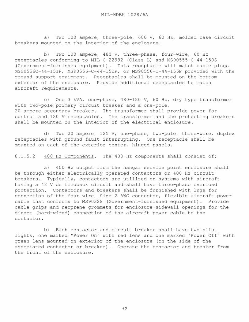
MIL-HDBK 1028/6A
4949
a) Two 100 ampere, three-pole, 600 V, 60 Hz, molded case circuitbreakers mounted on the interior of the enclosure.
b) Two 100 ampere, 480 V, three-phase, four-wire, 60 Hzreceptacles conforming to MIL-C-22992 (Class L) and MS90555-C-44-150S(Government-furnished equipment). This receptacle will match cable plugsMS90556C-44-151P, MS90556-C-44-152P, or MS90556-C-44-156P provided with theground support equipment. Receptacles shall be mounted on the bottomexterior of the enclosure. Provide additional receptacles to matchaircraft requirements.
c) One 3 kVA, one-phase, 480-120 V, 60 Hz, dry type transformerwith two-pole primary circuit breaker and a one-pole,20 ampere secondary breaker. The transformer shall provide power forcontrol and 120 V receptacles. The transformer and the protecting breakersshall be mounted on the interior of the electrical enclosure.
d) Two 20 ampere, 125 V, one-phase, two-pole, three-wire, duplexreceptacles with ground fault interrupting. One receptacle shall bemounted on each of the exterior center, hinged panels.
8.1.5.2 400 Hz Components. The 400 Hz components shall consist of:
a) 400 Hz output from the hangar service point enclosure shallbe through either electrically operated contactors or 400 Hz circuitbreakers. Typically, contactors are utilized on systems with aircrafthaving a 48 V dc feedback circuit and shall have three-phase overloadprotection. Contactors and breakers shall be furnished with lugs forconnection of the four-wire, Size 2 AWG conductor, flexible aircraft powercable that conforms to MS90328 (Government-furnished equipment). Providecable grips and neoprene grommets for enclosure sidewall openings for thedirect (hard-wired) connection of the aircraft power cable to thecontactor.
b) Each contactor and circuit breaker shall have two pilotlights, one marked "Power On" with red lens and one marked "Power Off" withgreen lens mounted on exterior of the enclosure (on the side of theassociated contactor or breaker). Operate the contactor and breaker fromthe front of the enclosure.

MIL-HDBK 1028/6A
5050
APPENDIX AMETRIC EQUIVALENT CHART
The following metric equivalents are approximate and were developed inaccordance with ASTM E380, Use of the International System of Units (SI)and ASTM E621, Use of Metric (SI) Units in Building Design andConstruction.
English (yd) Metric (m) 7000 6,401
1700 1,554
English (ft) Metric (m) 1200 366
500 152 200 61 50 15
English (ft) Metric (mm) 70 21 325
48 14 625 24 7325 20 6100 12 3660 10 3000 8 2450 6 1850 5 1500 4 1220 3 915 1 305
English (in.) Metric (mm) 2000 50 800
70 1775 36 1000 30 750 26 660 25 625

MIL-HDBK 1028/6A
5151
APPENDIX A (Continued)
English (sq. ft ) Metric (sq. m )
450 41.8 150 13.95 1 0.093
English (fpm) Metric (m/s)
75 0.381 60 0.305 50 0.250
English (cfm) Metric (cu. m/s)
150 0.0708 50 0.0236 40 0.0189 7.5 0.0037 1 0.0005
English (lb) Metric (kg)
18 000 816512 000 (6 T) 544310 000 (5 T) 4536 6000 (3 T) 2725 4000 (2 T) 1814 3000 1361 2000 (1 T) 907 500 230
English (lb/hr) Metric (kg/s)
200 0.0252
English (psf) Metric (Pa)
300 14 364 100 4788 4000 27 579 200 125 861 850 100 689 480 90 620 532 60 413 688 30 206 844
(Inch of Water at 39.2 degrees F)
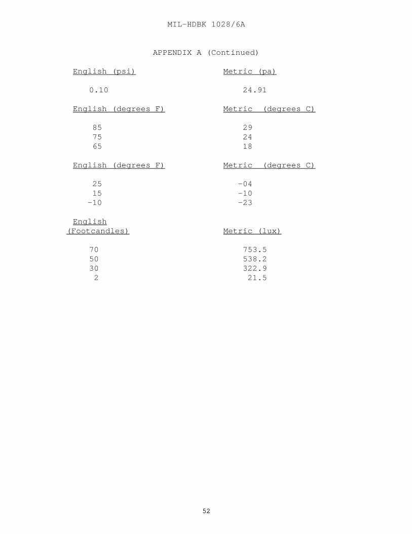
MIL-HDBK 1028/6A
5252
APPENDIX A (Continued)
English (psi) Metric (pa)
0.10 24.91
English (degrees F) Metric (degrees C)
85 29 75 24 65 18
English (degrees F) Metric (degrees C)
25 -04 15 -10 -10 -23
English (Footcandles) Metric ( lux)
70 753.550 538.230 322.9 2 21.5
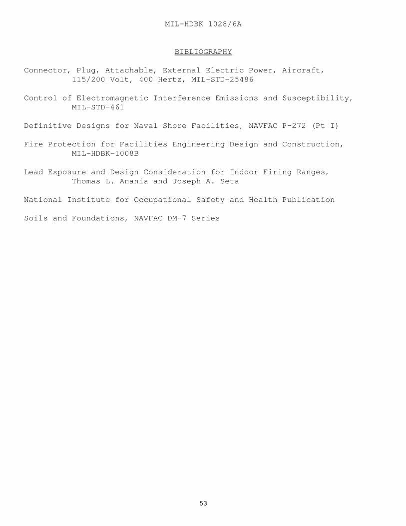
MIL-HDBK 1028/6A
5353
BIBLIOGRAPHY
Connector, Plug, Attachable, External Electric Power, Aircraft,115/200 Volt, 400 Hertz, MIL-STD-25486
Control of Electromagnetic Interference Emissions and Susceptibility,MIL-STD-461
Definitive Designs for Naval Shore Facilities, NAVFAC P-272 (Pt I)
Fire Protection for Facilities Engineering Design and Construction,MIL-HDBK-1008B
Lead Exposure and Design Consideration for Indoor Firing Ranges,Thomas L. Anania and Joseph A. Seta
National Institute for Occupational Safety and Health Publication
Soils and Foundations, NAVFAC DM-7 Series
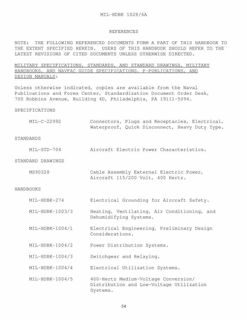
MIL-HDBK 1028/6A
5454
REFERENCES
NOTE: THE FOLLOWING REFERENCED DOCUMENTS FORM A PART OF THIS HANDBOOK TOTHE EXTENT SPECIFIED HEREIN. USERS OF THIS HANDBOOK SHOULD REFER TO THELATEST REVISIONS OF CITED DOCUMENTS UNLESS OTHERWISE DIRECTED.
MILITARY SPECIFICATIONS, STANDARDS, AND STANDARD DRAWINGS, MILITARYHANDBOOKS, AND NAVFAC GUIDE SPECIFICATIONS, P-PUBLICATIONS, ANDDESIGN MANUALS:
Unless otherwise indicated, copies are available from the NavalPublications and Forms Center, Standardization Document Order Desk,700 Robbins Avenue, Building 4D, Philadelphia, PA 19111-5094.
SPECIFICATIONS
MIL-C-22992 Connectors, Plugs and Receptacles, Electrical, Waterproof, Quick Disconnect, Heavy Duty Type.
STANDARDS
MIL-STD-704 Aircraft Electric Power Characteristics.
STANDARD DRAWINGS
MS90328 Cable Assembly External Electric Power, Aircraft 115/200 Volt, 400 Hertz.
HANDBOOKS
MIL-HDBK-274 Electrical Grounding for Aircraft Safety.
MIL-HDBK-1003/3 Heating, Ventilating, Air Conditioning, and Dehumidifying Systems.
MIL-HDBK-1004/1 Electrical Engineering, Preliminary Design Considerations.
MIL-HDBK-1004/2 Power Distribution Systems.
MIL-HDBK-1004/3 Switchgear and Relaying.
MIL-HDBK-1004/4 Electrical Utilization Systems.
MIL-HDBK-1004/5 400-Hertz Medium-Voltage Conversion/ Distribution and Low-Voltage Utilization Systems.
MIL-HDBK 1028/6A
5555
MIL-HDBK-1004/6 Lightning Protection.
MIL-HDBK-1021/4 Rigid Pavement Design for Airfields.
MIL-HDBK-1028/1 Aircraft Maintenance Facilities.
GUIDE SPECIFICATIONS
NFGS-16302 Underground Transmission and Distribution.
NFGS-16320 Exterior Lighting.
P-PUBLICATIONS
P-80 Facility Planning for Navy and Marine Corps Shore Installations.
P-355 Seismic Design for Buildings.
DESIGN MANUALS
DM-1 series Architecture.
DM-2 series Structural Engineering.
DM-3 series Mechanical Engineering.
DM-3.05 Compressed Air and Vacuum Systems.
DM-4 series Electrical Engineering.
DM-21 series Airfield Pavement Design.
DM-21.3 Flexible Pavement Design for Airfields.
NON-GOVERNMENT PUBLICATIONS:
AMERICAN NATIONAL STANDARDS INSTITUTE (ANSI)
ANSI C2 National Electrical Safety Code.
ANSI B31.1 Power Piping.
(Unless otherwise indicated, copies are available from the AmericanNational Standards Institute (ANSI), 11 West 42nd Street, New York,NY 10036.)
MIL-HDBK 1028/6A
5656
AMERICAN SOCIETY FOR TESTING AND MATERIALS (ASTM)
ASTM A 53 Pipe, Steel, Black and Hot-Dipped, Zinc-Coated, Welded, and Seamless.
ASTM E 380 Use of the International System of Units (SI).
ASTM E 621 Use of Metric (SI) Units in Building Design and Construction.
(Unless otherwise indicated, copies are available from the American Societyfor Testing and Materials (ASTM), 1916 Race Street, Philadelphia, PA 19103-1187.)
AMERICAN SOCIETY OF MECHANICAL ENGINEERS (ASME)
ASME Boiler and Pressure Vessel Code, Section VIII, Unfired Pressure Vessels.
(Unless otherwise indicated, copies are available from the American Societyof Mechanical Engineers (ASME), 345 East 47th Street, New York, NY 10017.)
BUILDING OFFICIALS AND CODE ADMINISTRATORS INTERNATIONAL ASSOCIATION (BOCA)
BOCA International Plumbing Code.
(Unless otherwise indicated, copies are available from Building Officialsand Code Administrators International Association (BOCA), 4051 WestFlossmor Road, Country Club Hills, IL 60478-5795.)
NATIONAL FIRE PROTECTION ASSOCIATION (NFPA)
NFPA 70 National Electrical Code.
(Unless otherwise indicated, copies are available from National FireProtection Association (NFPA), One Batterymarch Park, P.O. Box 9101,Quincy, MA 02269-9101.)

MIL-HDBK 1028/6A
5757
GLOSSARY
ECS. Environmental control system.
FPUS. Fixed point utility systems.
GSE. Ground support equipment.
NAVAIR. Naval Air Systems Command.
NAVFACENGCOM. Naval Facilities Engineering Command.
NEMA. National Electrical Manufacturers Association.
PVC. Polyvinyl chloride.
CUSTODIAN PREPARING ACTIVITY NAVY YD2 NAVY YD2
PROJECT NO. FACR-1147
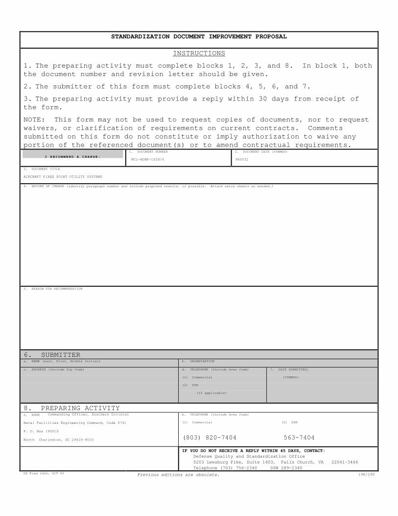
STANDARDIZATION DOCUMENT IMPROVEMENT PROPOSAL
INSTRUCTIONS
1. The preparing activity must complete blocks 1, 2, 3, and 8. In block 1, boththe document number and revision letter should be given.
2. The submitter of this form must complete blocks 4, 5, 6, and 7.
3. The preparing activity must provide a reply within 30 days from receipt ofthe form.
NOTE: This form may not be used to request copies of documents, nor to requestwaivers, or clarification of requirements on current contracts. Commentssubmitted on this form do not constitute or imply authorization to waive anyportion of the referenced document(s) or to amend contractual requirements.
I R E C O M M E N D A C H A N G E :
1. DOCUMENT NUMBER
MIL-HDBK-1028/6
2. DOCUMENT DATE (YYMMDD)
960531
3. DOCUMENT TITLE
AIRCRAFT FIXED POINT UTILITY SYSTEMS
4. NATURE OF CHANGE (identify paragraph number and include proposed rewrite, if possible. Attach extra sheets as needed.)
5. REASON FOR RECOMMENDATION
6. SUBMITTERa. NAME (Last, First, Middle Initial) b. ORGANIZATION
c. ADDRESS (Include Zip Code) d. TELEPHONE (Include Area Code)
(1) Commercial
(2) DSN
(If applicable)
7. DATE SUBMITTED:
(YYMMDD)
8. PREPARING ACTIVITYa. NAME Commanding Officer, Southern Division
Naval Facilities Engineering Command, Code 0741
P. O. Box 190010
North Charleston, SC 29419-9010
b. TELEPHONE ( Include Area Code)
(1) Commercial (2) DSN
(803) 820-7404 563-7404
IF YOU DO NOT RECEIVE A REPLY WITHIN 45 DAYS, CONTACT:Defense Quality and Standardization Office5203 Leesburg Pike, Suite 1403, Falls Church, VA 22041-3466Telephone (703) 756-2340 DSN 289-2340
DD Form 1426, OCT 89 Previous editions are obsolete. 198/290