unified facilities criteria (ufc) architecture · facility planning and design; the atlantic...
TRANSCRIPT

UFC 3-101-01 28 November 2011
Change 3, 20 June 2016
UNIFIED FACILITIES CRITERIA (UFC)
APPROVED FOR PUBLIC RELEASE; DISTRIBUTION UNLIMITED
ARCHITECTURE

UFC 3-101-01 28 November 2011
Change 3, 20 June 2016
UNIFIED FACILITIES CRITERIA (UFC)
ARCHITECTURE Any copyrighted material included in this UFC is identified at its point of use. Use of the copyrighted material apart from this UFC must have the permission of the copyright holder. U.S. ARMY CORPS OF ENGINEERS NAVAL FACILITIES ENGINEERING COMMAND (Preparing Activity) AIR FORCE CIVIL ENGINEER SUPPORT AGENCY Record of Changes (changes are indicated by \1\ ... /1/) Change No. Date Location 1 1 Nov 2015 1. Acoustics criteria added: paragraph 3-7, 4-8,
Figures 4-1, 4-2, 5-3.3, Appendix B-6.6. 2. Added Appendix C Daylighting Best Practices.
This material was revised and relocated from UFC 3-530-01. Referenced from 3-3.
3. Added requirements of ETL 04-3, Design Criteria for Prevention of Mold in Air Force Facilities, which is rescinded upon publication of this UFC: 2-5.2 (moved to 3-5.4), 2-6, 3-2, 3-5.2.1, 3-5.2.3, 3-5.2.4, 3-6.1.3, and 4-6 .
4. Other editorial and formatting changes throughout (replaced “shall” with “must”). Paragraphs 2-2.2, 2-6, 3-1, 3-4, 3-5.2, 3-5, 3-6.3, 4-2, 4-6, 4-7, 5-3.3, 5-3.5, and Appendix A, Appendix B, B-6.6, Appendix D, and Appendix E.
5. Aligned with 1-200-02. Removed dates from energy standards, dates are in Appendix A. Modified 5-3.3 12
6. 2-5.1 Added reference to OPNAV M5090.1 for Radon.
7. Revised underslab insulation 3-4. 8. Incorporated ccr responses: 1619, 1731, 1752,
1753, 1755, 1800, 1840, 1841, 2677, 2736, 3190, 3416, 3442, 3852, 3943, 3992, and 4731.

UFC 3-101-01 28 November 2011
Change 3, 20 June 2016
2. 1 March, 2016
1. Paragraph 2-2.1: Transferred guidance for calculating square footage for interior public corridor’s for Army UEPHs from UFC 4-721-11.1, which is now inactive.
2. Paragraph 5-3.5(9). Added clarification on wall type designations to support BIM.
3. 1 June 2016 1. 2-5 Hazard Prevention. Added reference to 29 CFR 1910.27 for fixed ladder design.
2. Added 2-5.2 Paints with Lead, Cadmium and Chromium (ccr 4874).
3. Appendix B-6.4 Added additional guidance for air barriers; also provided more guidance on dealing with air barriers in a renovation and repair project.
This UFC supersedes UFC 3-100-10, Architecture (Navy Draft), dated July 2006; MIL HDBK 1190, Facility Planning and Design; the Atlantic Division Architectural Design Guide and Interior Design Guide, dated July 2002; SODIV-TG-1001, dated March 1997; and SODIV-TG-1007, dated August 1997.

UFC 3-101-01 28 November 2011
Change 3, 20 June 2016
This page intentionally left blank.

UFC 3-101-01 28 November 2011
Change 3, 20 June 2016
FOREWORD The Unified Facilities Criteria (UFC) system is prescribed by MIL-STD 3007 and provides planning, design, construction, sustainment, restoration, and modernization criteria, and applies to the Military Departments, the Defense Agencies, and the DoD Field Activities in accordance with USD (AT&L) Memorandum dated 29 May 2002. UFC will be used for all DoD projects and work for other customers where appropriate. All construction outside of the United States is also governed by Status of Forces Agreements (SOFA), Host Nation Funded Construction Agreements (HNFA), and in some instances, Bilateral Infrastructure Agreements (BIA.) Therefore, the acquisition team must ensure compliance with the most stringent of the UFC, the SOFA, the HNFA, and the BIA, as applicable. UFC are living documents and will be periodically reviewed, updated, and made available to users as part of the Services’ responsibility for providing technical criteria for military construction. Headquarters, U.S. Army Corps of Engineers (HQUSACE), Naval Facilities Engineering Command (NAVFAC), and Air Force \2\ Civil Engineer Center (AFCEC) /2/ are responsible for administration of the UFC system. Defense agencies should contact the preparing service for document interpretation and improvements. Technical content of UFC is the responsibility of the cognizant DoD working group. Recommended changes with supporting rationale should be sent to the respective service proponent office by the following electronic form: Criteria Change Request. The form is also accessible from the Internet sites listed below. UFC are effective upon issuance and are distributed only in electronic media from the following source:
• Whole Building Design Guide web site http://dod.wbdg.org/. Hard copies of UFC printed from electronic media should be checked against the current electronic version prior to use to ensure that they are current. AUTHORIZED BY:
JAMES C. DALTON, P.E. JOSEPH E. GOTT, P.E. Chief, Engineering and Construction Chief Engineer U.S. Army Corps of Engineers Naval Facilities Engineering Command
TERRY G. EDWARDS, P.E. MICHAEL McANDREW Director, Air Force Center for Engineering and the Environment
Director, Facility Investment and Management
Department of the Air Force Office of the Deputy Under Secretary of Defense (Installations and Environment)

UFC 3-101-01 28 November 2011
Change 3, 20 June 2016
i
UNIFIED FACILITIES CRITERIA (UFC) NEW SUMMARY SHEET
Document: UFC 3-101-01 unifies the architectural criteria for DOD. Superseding: None
Description: Provide a brief description of purpose, scope, and applicability.
Reasons for Changes : • Maximizes use of industry standards to meet DOD requirements.
• Incorporates critical architectural text from Military Handbook 1190,
“FACILITY PLANNING AND DESIGN GUIDE”, dated September, 1987.
• Incorporates additional building envelope criteria that will help meet EPAct 2005, EISA 2007, ANSI/ASHRAE/IESNA 90.1, and portions of ANSI/ASHRAE/USGBC/IES 189.1 requirements
Impact: There will be some initial construction cost impacts to meeting the new building envelope criteria, but there should be long-term life cycle cost savings in reduced energy usage and building maintenance. The following additional benefits should be realized.
• Assists the government in meeting EPAct 2005 and EISA 2007 requirements.
• By using the industry standards, on-going revision due to industry
changes will minimize the need for future revisions. Unification Issues
• Referenced space planning criteria is contained in service specific publications : For Air Force use AFMAN 32-1084, “Facility Requirements”; for the Army use TM 5-803-5, “Installation Design” and model design-build RFP and standard designs, as applicable; and for the Navy use UFC 2-000-05N (P-80), “Facility Planning Criteria for Navy/Marine Corps Shore Installations” .
• Radon identification guidance is service specific.
• The building envelope must be designed to comply with or exceed ANSI/ASHRAE/USGBC/IES 189.1 paragraph 7.4.2.1. For Air Force projects, the building envelope must be designed to comply with or exceed ANSI/ASHRAE/IESNA 90.1.
• Service differences in Air Barrier Testing criteria are noted in this UF

UFC 3-101-01 28 November 2011
Change 3, 20 June 2016
ii
CONTENTS
CHAPTER 1 INTRODUCTION ....................................................................................... 1
1-1 PURPOSE AND SCOPE. .......................................................................... 1
1-2 APPLICABILITY. ....................................................................................... 1
1-3 GENERAL BUILDING REQUIREMENTS. ................................................ 1
1-4 REFERENCES. ......................................................................................... 1
1-5 ADDITIONAL REQUIREMENTS. .............................................................. 2
1-6 GLOSSARY ............................................................................................... 2
CHAPTER 2 PROGRAMMING AND PLANNING .......................................................... 3
2-1 SPACE PLANNING CRITERIA. ................................................................ 3
2-2 BUILDING AREA CALCULATIONS. ........................................................ 3
2-2.1 Scope Changes. .................................................................................... 3
2-2.2 Calculation of Gross Building Area. ....................................................... 3
2-3 BUILDING ORIENTATION. ....................................................................... 7
2-4 ARCHITECTURAL STYLE AND CHARACTER. ...................................... 7
2-4.1 Installation Exterior Architectural Guidelines. ......................................... 7
2-4.2 Historic Architecture. .............................................................................. 7
2-4.3 Projects in the National Capital Region (NCR). ..................................... 7
2-5 HAZARD PREVENTION. .......................................................................... 8
2-5.1 Radon. ................................................................................................... 8
2-5.2 Paints with Lead, Cadmium and Chromium ........................................... 9
2-6 MECHANICAL/ELECTRICAL/TELECOMMUNICATION ROOMS. .......... 9
CHAPTER 3 BUILDING ENVELOPE REQUIREMENTS ............................................. 11
3-1 INTRODUCTION. .................................................................................... 11
3-2 CONTINUITY OF BARRIERS. ................................................................ 11
3-3 FENESTRATION. .................................................................................... 11
3-3.1 Selection of Windows and Glazing. ..................................................... 11
3-3.2 Fenestration Design. ............................................................................ 11
3-3.3 Daylighting. .......................................................................................... 12
3-4 INSULATION. .......................................................................................... 12
3-5 MOISTURE BARRIER. ............................................................................ 12

UFC 3-101-01 28 November 2011
Change 3, 20 June 2016
iii
3-5.1 Water-Resistive Barriers (WRB). ......................................................... 12
3-5.2 Vapor Retarders. ................................................................................. 13
3-5.3 Waterproofing. ..................................................................................... 15
3-5.4 Mold Mitigation and Prevention. ........................................................... 15
3-6 AIR BARRIER REQUIREMENTS. .......................................................... 15
3-6.1 New Construction. ............................................................................... 15
3-6.2 Renovations. ........................................................................................ 16
3-6.3 Inspection and Testing. ........................................................................ 16
3-6.4 Mock-ups. ............................................................................................ 17
3-7 ACOUSTICS - OUTSIDE TO INSIDE NOISE CONTROL ....................... 17
CHAPTER 4 SPECIFIC REQUIREMENTS................................................................... 19
4-1 INTRODUCTION. .................................................................................... 19
4-2 ABOVE-GRADE FINISHED FLOOR ELEVATION. ................................ 19
4-3 PAINT SELECTION................................................................................. 19
4-4 MASONRY .............................................................................................. 19
4-4.1 Masonry Control and Expansion Joints. .............................................. 19
4-4.2 Expansion Joint Position and Location. ............................................... 19
4-4.3 Masonry Water-Repellent Coatings. .................................................... 19
4-4.4 Plastic and Membrane Through-Wall Flashing. ................................... 20
4-4.5 Clearance Between Masonry and Back-up Construction. .................... 20
4-4.6 Flashing at Penetrations and Projections. ........................................... 20
4-4.7 Location of Weep Holes. ...................................................................... 20
4-5 EXTERIOR FINISH SYSTEMS (EFS) AND EXTERIOR INSULATION AND FINISH SYSTEMS (EIFS)............................................................. 20
4-6 GYPSUM BOARD CONSTRUCTION ..................................................... 21
4-7 FIRE-RESISTIVE RATED ASSEMBLIES ............................................... 21
4-8 INTERIOR ACOUSTICS. \1\ .................................................................... 21
CHAPTER 5 PRE-DESIGN, DESIGN AND POST-DESIGN SERVICES ...................... 25
5-1 GENERAL. .............................................................................................. 25
5-2 PRE-DESIGN SERVICES. ...................................................................... 25
5-3 DESIGN SERVICES. ............................................................................... 25
5-3.1 Functional Analysis Concept Development (FACD) and Design Charrettes. ........................................................................................... 25
5-3.2 Architectural Compatibility Submittal. .................................................. 25
UFC 3-101-01 28 November 2011
Change 3, 20 June 2016
iv
5-3.3 Architectural Basis of Design. .............................................................. 27
5-3.4 Specifications. ...................................................................................... 29
5-3.5 Architectural Drawings. ........................................................................ 29
5-3.6 Color Boards and Binders. ................................................................... 32
APPENDIX A REFERENCES ....................................................................................... 33
APPENDIX B BEST PRACTICES ................................................................................ 41
B-1 INTRODUCTION. .................................................................................... 41
B-2 WHOLE BUILDING DESIGN GUIDE. ..................................................... 41
B-3 PLANNING ISSUES. ............................................................................... 41
B-3.1 Building Orientation. ............................................................................ 41
B-3.2 Design for Flexibility. ............................................................................ 41
B-3.3 Design for Function and Life Cycle. ..................................................... 41
B-4 LANDSCAPING INTERFACE. ................................................................ 42
B-5 LOCAL CONSTRUCTION METHODS, MATERIALS AND SKILLS....... 42
B-6 BUILDING ENVELOPE. .......................................................................... 42
B-6.1 Heat. .................................................................................................... 43
B-6.2 Air. ....................................................................................................... 44
B-6.3 \1\/1/ Moisture. ..................................................................................... 45
B-6.4 Air Barrier for Modifying an Existing Building. ...................................... 46
B-6.5 Light/Radiation. .................................................................................... 50
B-6.6 Noise.................................................................................................... 50
B-7 AIR BARRIER MOCK-UP TESTING ....................................................... 50
B-7.1 Guidance on When to Test \1\Mock-ups/1/ .......................................... 50
B-7.2 On Site Mockups. ................................................................................ 50
B-8 EXTERIOR INSULATION AND FINISH SYSTEM (EIFS). ...................... 53
APPENDIX C DAYLIGHTING BEST PRACTICES. ..................................................... 55
C-1 DAYLIGHTING ........................................................................................ 55
C-1.1 Benefits of Daylight .............................................................................. 55
C-1.2 Maximize Daylight Potential ................................................................. 56
C-1.3 Building Shape ..................................................................................... 56
C-1.4 Project Types that Benefit from Daylight .............................................. 58
C-1.5 Economics ........................................................................................... 58
C-2 GLAZING ORIENTATION ....................................................................... 59

UFC 3-101-01 28 November 2011
Change 3, 20 June 2016
v
C-2.1 Considerations ..................................................................................... 59
C-3 GLAZING CHARACTERISTICS ............................................................. 60
C-3.1 Considerations ..................................................................................... 60
C-4 QUANTITY OF GLAZING ....................................................................... 61
C-4.1 Considerations ..................................................................................... 64
C-5 GLARE AND CONTRAST CONTROL .................................................... 65
C-5.1 Considerations ..................................................................................... 65
C-6 AUTOMATED SHADING ........................................................................ 66
C-7 ACTIVE DAYLIGHTING .......................................................................... 66
C-7.1 Solar-adaptive shading ........................................................................ 67
C-8 PHYSICAL MODELING .......................................................................... 68
C-9 COMPUTER SIMULATION ..................................................................... 68
APPENDIX D GLOSSARY ........................................................................................... 69
D-1 ACRONYMS ............................................................................................ 69
D-2 DEFINITION OF TERMS ......................................................................... 72
FIGURES
Figure 2-1 Sample Gross Building Area Calculation ....................................................... 5 Figure 2-2 Sample Block Plan ......................................................................................... 6 Figure 3-1 Building Façade Sound Isolation .................................................................. 18 Figure 4-1Interior Acoustic Requirements for Typical Figure Spaces ........................... 22 Figure 4-2 Acoustic Requirements for Typical Facilities ................................................ 23 Figure B-1 Construction Mock-Up Guidance Matrix ...................................................... 52 Figure C-1. Effects of Building Massing on Daylight Availability .................................... 57 Figure C-2 Examples of Daylighting Strategies ............................................................. 58 Figure C-3. Building Orientation Can Maximize Daylight Exposure .............................. 59 Figure C-4. Example of Architectural Shading Devices ................................................. 59 Figure C-5 Diagrams of Toplighting Strategies ............................................................. 62 Figure C-6 Examples of Toplighting Applications .......................................................... 63 Figure C-7 Example of Clerestory Application ............................................................... 63 Figure C-8 Examples of Sidelighting Applications ......................................................... 64 Figure C-9 Examples of Roof Shapes ........................................................................... 65 Figure C-10 Example of Splayed Skylights ................................................................... 65 Figure C-11 Example of an Active Daylighting System that Tracks the Sun and Directs
Daylight into the Building. ....................................................................................... 67 Figure C-12 Example of Solar-Adaptive Shading .......................................................... 67
TABLES Table C-1 Comparison of Glass Types (from AlpenGlass Heat Mirror) ......................... 60

UFC 3-101-01 28 November 2011
Change 3, 20 June 2016
1
CHAPTER 1 INTRODUCTION
1-1 PURPOSE AND SCOPE.
This UFC provides technical guidance and outlines technical requirements for typical aspects of architectural design services. Architects must use the information in this document in the development of plans, specifications, calculations, construction contract documents, and Design-Build Requests for Proposals (RFP). The information in this guide serves as the minimum architectural requirements. Project conditions may dictate the need for designs that exceed these requirements.
1-2 APPLICABILITY.
This UFC applies to all agencies of the U.S. Armed Services and their contractors that are preparing construction contract documents for all Department of Defense-owned facilities. These criteria are applicable in the fifty states, the District of Columbia, Puerto Rico, U.S. territories and possessions, and as far as practical, at installations in foreign countries. This UFC applies to all types of construction regardless of funding, including properties listed or eligible for listing on the National Register of Historic Places, as well as National Guard and Reserve projects constructed on military installations or non-military DoD property. Certain specialized facilities, such as health facilities, carry more stringent requirements. See UFC or other criteria that are applicable to the respective specialized facility that is being designed. This UFC is applicable to the traditional architectural services customary for Design-Bid-Build design services and for Design-Build construction contracts.
1-3 GENERAL BUILDING REQUIREMENTS.
UFC 1-200-01, “General Building Requirements”, provides applicability of model building codes and government-unique criteria for typical design disciplines and building systems, as well as for accessibility, antiterrorism, security, sustainability, and safety. Use this UFC in addition to UFC 1-200-01 and the UFCs and government criteria
1-4 REFERENCES.
Other technical criteria may apply and must be followed as appropriate for each project. Confirm the most recent required criteria with the Project Manager/Design Manager. Furthermore, Appendix A of this UFC contains the list of references used in this UFC. These other publications, standards, and technical data referenced herein form a part of these criteria to the extent referenced.

UFC 3-101-01 28 November 2011
Change 3, 20 June 2016
2
1-5 ADDITIONAL REQUIREMENTS.
When performing work for different Activities within the U.S., additional regional or service-specific requirements apply. Confirm with the Authority Having Jurisdiction (AHJ) the applicability of any regional requirements.
1-6 GLOSSARY
Appendix D contains acronyms, abbreviations, and terms.

UFC 3-101-01 28 November 2011
Change 3, 20 June 2016
3
CHAPTER 2 PROGRAMMING AND PLANNING
2-1 SPACE PLANNING CRITERIA.
Program non-standardized facility sizes based on a functional analysis of activities to be accommodated to determine the actual amount of space required. Facility planning must be based on specific requirements for each project, to include all functional, technical, and economic considerations, instead of arbitrary allowances. To obtain the most economical and efficient use of space, design facilities based on the functional organization of adequately sized spaces. The following publications contain tables of allowances for general planning purposes, but the final size of each project must be based on actual requirements:
• AFMAN 32-1084, “Facility Requirements”
• TM 5-803-5, “Installation Design” and model design-build RFP and standard designs, as applicable
• UFC 2-000-05N (P-80), “Facility Planning Criteria for Navy/Marine Corps Shore Installations”
The documents above are used to determine general facility requirements. Other facility-specific UFCs may have more detailed requirements.
2-2 BUILDING AREA CALCULATIONS.
Include in the Basis of Design the gross floor area calculation to confirm scope and criteria compliance. Include a block diagram indicating the building outline and all areas that contribute to the building area. Gross area definitions and calculations must conform to this UFC. Provide calculations in accordance with Chapter 5 paragraph Architectural Basis of Design of this document, applying the appropriate factor for full or half area to each area as defined herein. Figures 2-1 and 2-2 illustrate a sample gross building area calculation and block diagram.
2-2.1 Scope Changes.
Changes to scope are governed by Title 10 USC 2853.
2-2.2 Calculation of Gross Building Area.
Other UFCs for specialized facilities such as medical facilities, \1\family housing, or unaccompanied housing/1/ \2\provide additional guidance regarding/2/ how to calculate the gross area of those facilities. For all other facilities, calculate the gross area of a building using the following:
• Enclosed spaces: The gross area includes the total area of all floors, including mezzanines, basements, penthouses, and other enclosed spaces as measured from the exterior faces of the exterior walls or from

UFC 3-101-01 28 November 2011
Change 3, 20 June 2016
4
the centerline of walls separating joined buildings. Enclosed stairwells, elevators, utility chases, and mechanical rooms are included as part of the area of each floor that they occupy. \1\
• Unenclosed programmed facilities: For covered outdoor facilities with no exterior walls, where the area is programmed by the space function (i.e. walls are not required and only a roof is necessary to perform its designated function) the facility gross square footage is the total area measured under the roof. Refer to individual service component planning documents for programmed areas of these spaces./1/
• One-Half Spaces: Include one-half of the gross area of paved or finished covered areas, such as balconies and porches, covered but not enclosed entrances, covered raised loading platforms, covered ground level or depressed loading facilities, covered but not enclosed walks or passageways, covered and uncovered but not enclosed exterior stairs, and covered ramps. \2\ For Army Unaccompanied Enlisted Personnel Housing (UEPH) calculate interior public corridors as one-half space; calculate circulation spaces within the living unit as full area. /2/.
• Excluded Spaces: Exclude the following when the average ceiling height is less than 7 ft (2.1 m) measured from the underside of a structural system and with perimeter walls measuring a minimum of 59 in. (1500mm) in height: mezzanines; interstitial spaces; penthouses; and enclosed crawl and utility spaces such as tunnels, raceways, and trenches. Also exclude from the gross area the following: catwalks; mechanical platforms; stairs on the roof; exterior uncovered walks; ramps; stoops; uncovered loading platforms or facilities, either depressed, ground level, or raised; open courtyards; open paved terraces; and roof overhangs, shading devices, and soffits. Prefabricated enclosures housing equipment are considered equipment and are also excluded. The void areas of atria are also excluded. Only include the floor area of the lowest level of atria.

UFC 3-101-01 28 November 2011
Change 3, 20 June 2016
5
Figure 2-1 Sample Gross Building Area Calculation
PROJECT TITLE PROJECT LOCATION GROSS FLOOR AREA CALCULATION * (SEE BLOCK PLAN EXAMPLE) AREA A Area A 124’-6” x 52’-4” = 6515.5 sf AREA A TOTAL 6515.5 sf 605.3 sm AREAS A1 thru A5 (Exterior Covered – ½ Area) Area A1 17’-0” x 7’-0” / 2= 59.5 sf Area A2 42’-3” x 7’’-0” / 2= 148.0 sf Area A3 22’-8” x 7’-0” / 2= 79.0 sf Area A4 17’-0” x 7’-0” / 2= 59.5 sf Area A5 10’-6” x 9’-0” / 2= 47.0 sf AREAS A1 thru A5 TOTAL 393.0 sf 36.5 sm AREA B Area B 9’-0” x 32’-4” = 291.0 sf 27.0 sm AREA B1 (Exterior Covered – ½ Area) Area B1 9’-0” x 5’-3” / 2= 24.0 sf AREA B1 TOTAL 24.0 sf 2.2 sm BUILDING TOTAL GROSS 7,223.5 sf 670.9 sm SCOPE TOTAL MAX. ALLOWABLE GROSS AREA* 7,224 sf 671 sm (PER DD FORM 1391) *Calculations may be in metric or Inch-pound, as directed by the Government Project Manager.

UFC 3-101-01 28 November 2011
Change 3, 20 June 2016
6
Figure 2-2 Sample Block Plan

UFC 3-101-01 28 November 2011
Change 3, 20 June 2016
7
2-3 BUILDING ORIENTATION.
Building siting must be established in consonance with the Base Development Plan and land use compatibility respective of mission requirements. Building layout and orientation must optimize site opportunities with regard to functional arrangement, access, exterior appearance, \1\and views, present and expected future site acoustic conditions, and other considerations./1/
Building shape, orientation and design must utilize the site seasonal environmental factors to minimize annual facility energy use and to optimize daylighting. Coordinate building and glazing orientation and architectural shading with seasonal solar angles and prevailing winds to enhance energy performance of the building within the site-specific micro climate. \1\See Appendix B Best Practices and Appendix C Daylighting for additional information. /1/
2-4 ARCHITECTURAL STYLE AND CHARACTER.
Facilities must be designed in harmony with the surrounding base architecture, judiciously employing the style and character of architecturally and historically significant facilities, as appropriate. Constructability, maintainability, and sustainability must be considered in design in attaining architectural compatibility.
2-4.1 Installation Exterior Architectural Guidelines.
Most military installations and/or service design agencies have published design guidelines that contain criteria relative to achieving, maintaining and emphasizing a positive exterior visual environment. Follow the design guidance contained in these documents carefully since these are published under the authority of the Secretaries of the military services. In the absence of such guidelines, design facilities to harmonize with the character of existing facilities considered historically or architecturally significant to the area.
2-4.2 Historic Architecture.
Repair or renovation of historic facilities and new construction near historic facilities must follow the Secretary of Interior’s Standards for Rehabilitation and Guidelines for Rehabilitating Historic Buildings.
2-4.3 Projects in the National Capital Region (NCR).
In accordance with the National Capital Planning Act of 1952, as amended, submit all master plans and designs for proposed construction projects in the NCR to the National Capital Planning Commission (NCPC) for appropriate reviews and approvals consistent with the timelines issued by the NCPC.

UFC 3-101-01 28 November 2011
Change 3, 20 June 2016
8
2-5 HAZARD PREVENTION.
Design facilities to comply with 29 CFR Occupational Safety and Health Act (OSHA). Pay particular attention to lead and asbestos particulates, which may be lying on top of materials to be removed, or Polychlorinated biphenyls (PCBs) that are part of caulking and sealant materials that may have been absorbed into adjacent building materials and need grinding.
\3\Design fixed ladders in accordance with 29 CFR 1910.27./3/
2-5.1 Radon.
Evaluate and mitigate Radon per the appropriate Service and Installation regulations. \1\For Navy requirements follow OPNAV M-5090.1 paragraph 25-3.2 Radon, including Navy’s Radon Assessment and Mitigation Program (NAVRAMP). /1/
2-5.1.1 Identification of Radon
2-5.1.1.1 Army and Navy. Check the Environmental Protection Agency’s (EPA's) Map of Radon Zones (by state), EPA 402-R-93-071, to determine the radon priority area.
2-5.1.1.2 Navy \1\. NAVRAMP provides for compliance with the procedural requirements of the Toxic substances Control Act (TSCA) related to radon. For existing buildings check the results of the NAVRAMP survey by contacting the NAVFAC Facility Engineering Command (FEC) Air Pollution Engineer. /1/
2-5.1.1.3 Air Force. Check the results of the AF Radon Assessment and Mitigation Program (RAMP) study of 1987. During that study, all Air Force Installations were screened for radon in existing structures. Installations were classified as being of low, medium or high risk. Incorporate radon reduction measures in the construction of new facilities at those installations designated as medium or high risk. See AFI 48-148. For installations not assessed during the RAMP study of 1987 and for all new, permanent operating locations, a random sampling of the site’s structures must be assessed for radon. Consult with the Air Force Institute of Environment, Safety, Occupational Health and Risk Analysis (AFIERA) for guidance on designing an appropriate sampling program. Any Installation or operating location found to have a single structure with radon concentrations greater than the threshold limit listed in AFI 48-148 must undergo a detailed radon assessment.
2-5.1.1.4 If no data is available for the area or site to make a prediction of radon levels, then a radon survey must be done or a passive radon mitigation system installed.
2-5.1.2 Radon Mitigation System Design. Provide passive under-slab depressurization systems for projects located in Priority Areas No. 1 (predicted average radon level is greater than 4/pCi/L). Change the system to active, if needed,

UFC 3-101-01 28 November 2011
Change 3, 20 June 2016
9
based on follow-up testing. Check the following EPA documents available from the EPA Radon Information Center, \1\(703) 356-5345, http://www.epa.gov/radon/pubs/./1/
• EPA's Model Standards and Techniques for Control of Radon in New Residences, U.S. Environmental Protection Agency, Air and Radiation (6604-J), EPA 402-R-94-009,.
• Radon Prevention in the Design and Construction of Schools and Other Large Buildings, EPA/625/R-92-016,
• Radon Measurement in Schools, EPA/402/R-92-014. \3\
2-5.2 Paints with Lead, Cadmium and Chromium
Painted surfaces containing lead, cadmium, chromium and operations involving these and other heavy metals are regulated by the Occupational Safety and Health Act (OSHA) and the Resource Conservation and Recovery Act (RCRA). Paints containing lead, cadmium and chromium are often found as protective coatings on structural steel, tanks, piping, metal building components, exterior coatings on metal surfaces, aircraft and ships. Paints containing lead, cadmium, chromium and other heavy metals are used in current operational processes in various facilities, such as, aircraft maintenance hangars, ship maintenance and repair facilities, etc. If not properly controlled and managed, dust and/or particulates containing lead, cadmium, chromium and other heavy metals can be generated from operational activities resulting in contaminated dust deposits on building surfaces which must be remediated during renovation, alteration, repair or demolition activities. For Navy and Marine Corps projects involving renovation, alteration, repair, or demolition, comply with UFC 3-810-01N Navy and Marine Corps Environmental Engineering for Facility Construction.
Facilities with heavy metal paints or coatings, or facilities which operated or will operate utilizing heavy metals and/or chemicals in their operations, must comply with the Occupational Safety and Health Act 29 CFR 1910.141 General Environmental Controls, 29 CFR 1910.1025 Lead, 29 CFR 1910.1026 Chromium (VI), and 29 CFR 1910.1027 Cadmium. The requirements found in the CFR’s may affect facility design requirements, which include (but are not limited to): separate toilets and washing/bathing areas, change rooms, decontamination areas, clothes washing facilities, areas for controlled disposal of contaminated waste and work clothes, high-efficiency particulate air (HEPA) systems and filters, deluge showers, etc. Areas of facilities utilizing these heavy metals and/or chemicals must be designated as regulated areas whenever exposure can be expected to be in excess of the permissible exposure limit(s), and must be demarcated from the rest of the workplace in a manner that adequately establishes and alerts building occupants of the boundaries of the regulated area. Facilities must be designed in a manner to allow the performance of the OSHA and EPA air sampling and monitoring that are required for the specific hazardous metal and/or chemical in use./3/
2-6 MECHANICAL/ELECTRICAL/TELECOMMUNICATION ROOMS.

UFC 3-101-01 28 November 2011
Change 3, 20 June 2016
10
Design adequate area for mechanical equipment rooms, electrical rooms, and telecommunication rooms. \1\Provide sufficient floor-to-floor height, vertical distribution space, and mechanical equipment space to accommodate a ducted system to supply preconditioned ventilation air (when a ducted system is used.) /1/ Provide an adequate volume of space for all building distribution systems and provide access for maintenance. For mechanical equipment room sizing, coordinate with the mechanical designer at the earliest stage to ensure the required clearances for maintenance, servicing, and safety are included. For telecommunications rooms, coordinate with the electrical designer. \1\ For noise control, refer to Chapter 4 paragraph, Interior Acoustics./1/

11
UFC 3-101-01 28 November 2011
Change 3, 20 June 2016
CHAPTER 3 BUILDING ENVELOPE REQUIREMENTS
3-1 INTRODUCTION.
The building envelope must be designed to comply with or exceed ANSI/ASHRAE/USGBC/IES 189.1 paragraph 7.4.2.1 \1\ and 7.4.2.2./1/ For Air Force projects, the building envelope must be designed to comply with or exceed ANSI/ASHRAE/IESNA 90.1.
Design the building envelope to control the transfer of the following elements: heat, air, moisture, light/radiation, and noise. Design each control strategy holistically and use an integrated approach.
3-2 CONTINUITY OF BARRIERS.
There are several functions that a building enclosure must fulfill. In order to do so effectively, the following barriers in the building enclosure must be continuous: the rain screen or water deflection layer, the insulation or thermal barrier, the air barrier, the water drainage plane, and the waterproof barrier. It is desirable to have the vapor retarder as continuous as possible, but unlike the other barriers, it can function adequately with minor imperfections in continuity. Sometimes it is possible to combine functions in a single layer, for example, medium density spray polyurethane foam can be the air barrier, the thermal insulation, the water drainage plane and the vapor retarder. Continuity of the barriers must be traced through all details of the building enclosure.
3-3 FENESTRATION.
3-3.1 Selection of Windows and Glazing.
Fenestration is the least energy-efficient component of the building enclosure. Based on a life cycle cost analysis (LCCA), select windows and glazing with the best possible performance from a U-factor, Solar Heat Gain Coefficient (SHGC) and Visible Transmittance (VT) for the fenestration. Optimize the emissivity coatings to control both heat gain into the building due to solar radiation and heat loss from the building. Select framing that includes advanced thermal breaks of polyester-reinforced nylon. Wherever possible, select systems that incorporate pressure-equalized technology—face-sealed systems eventually break down and leak. Include flashings under fenestration in an appropriate manner. \1\Fenestration must meet both code and UFC 4-010-01 Anti-terrorism Force Protection (ATFP) requirements./1/
3-3.2 Fenestration Design.
Develop a comprehensive design that considers both exterior shading devices, including horizontal sunscreens and vertical fins (beneficial in hot southern climates), and interior shading devices (necessary to control glare when direct solar intrusion is inevitable). Optimize the window-to-wall ratio to (1) reduce lighting energy when using daylighting controls and (2) avoid the glare and added energy consumption that can

12
UFC 3-101-01 28 November 2011
Change 3, 20 June 2016
result from large window areas. Glazing areas above 7 ft. (2135mm) high are useful in increasing daylight penetration, especially when coupled with light-reflecting shelves. \1\Base design on life cycle cost effectiveness. /1/
Selection between windows, storefront and curtain wall must be coordinated with the structural design. Final fenestration design must be coordinated with the mechanical and electrical engineers to comply with overall facility energy requirements\1\
3-3.3 Daylighting.
Daylighting must comply with UFC 1-200-02 paragraph 2.5.3. See Appendix C for daylighting best practices. Use Appendix C-5 for strategies to optimize daylight entering the space while minimizing the effects of solar heat gain and glare.
3-4 INSULATION.
Where 3-1 Introduction requires insulation for slab-on-grade floors, use high-density (40-100 psi depending on floor loading with a safety factor of 5) extruded polystyrene under the vapor retarder. Apply requirements of ASCE 32-01 to keep soils thawed to minimize frost action in cold regions. Coordinate final assembly U-Factors with the mechanical engineer to comply with overall facility energy requirements. /1/
Protect all insulation from weather, including rain, ultra-violet solar radiation, mechanical abuse, compression, or accidental or deliberate movement from its location during its service life. Coordinate insulation and its installation with the moisture analysis described in Chapter 3, Vapor Retarders.
3-5 MOISTURE BARRIER.
A building should be wrapped on all “six” sides with a moisture barrier to deflect water from its surface. A moisture barrier may be a waterproof layer or a water-resistant material shingled to shed water, depending on the slope. Water-resistive barriers (WRBs) may not perform as a waterproofing material if subjected to hydrostatic water pressure. Some WRBs can be vapor permeable, some can be vapor retarders and some can be air barriers. Seal all penetrations of the moisture barrier.
Establish the specific functions of the membrane and its position relative to the other materials in the assembly determined so that its properties can be correctly selected and a “moisture balance” (more drying than increase in moisture content) will occur in the building assemblies.
3-5.1 Water-Resistive Barriers (WRB).
Wall assemblies must incorporate a WRB (meeting the requirements of Chapter 14 of the International Building Code (IBC) as a minimum) in the back-up wall behind the cladding, with flashings to lead water out. This is true for all claddings, including exterior insulation and finish systems (EIFS). \1\

13
UFC 3-101-01 28 November 2011
Change 3, 20 June 2016
3-5.1.1 Flashing. All copings and sills must receive through-wall flashing under them. /1/In order to direct moisture out of a cavity through weep holes, provide continuous flashing at the bottom of the cavity and wherever the cavity is interrupted by elements such as shelf angles, lintels and penetrations. Extend flashing through the outer masonry face and turn down at 450 to form a drip. Do not terminate through-wall flashing behind the exterior face. Install through-wall flashing over all openings, sills, spandrels, shelf angles and parapet copings. Where flashing is not continuous, such as over openings and at sills, extend flashing ends beyond the lintel on both sides and turn up into the head joint two inches at each end to form an end dam.
Penetrations such as windows and louvers in the exterior wall assemblies must have pan flashing installed in the rough opening sill. This pan sill flashing must have end dams at both jambs a minimum of 2 in. (50 mm) high and a rear dam of 2 in. (50 mm) high. Comply with ASTM E 2112, the requirements in Chapter 4, Masonry, and the SMACNA Architectural Sheet Metal Manual recommendations.\1\
3-5.1.2 Waterproofing, Damproofing, and Waterstops /1/Counteract below-grade transfer of water through walls by damp-proofing or waterproofing on walls, depending on hydrostatic pressure and drainage capability. Minimize capillary suction of water upwards from wet footings can be minimized by troweling a layer of cementitious crystalline waterproofing into the wet concrete on top of footings or by including a waterproofing admixture in the footing concrete mix. Footing drains and under-slab drainage must be incorporated based on the recommendations of the geotechnical engineering report. Waterstops must be provided at all concrete cold joints near or below grade. If required to address hydrostatic pressure or as recommended by the geotechnical report, provide drainage planes combined with waterproofing material and a footing drain on below- grade walls.
3-5.2 Vapor Retarders.
3-5.2.1 Building Envelope Vapor Retarders. \1\Design the building envelope to control the movement of moisture and air with the effective use of water vapor retarders and air infiltration barriers. Design envelope sections to prevent condensation on interior surfaces or within wall/roof sections that would support mold growth. Follow vapor retarder requirements listed in the IBC Section 1405. For building enclosure systems or environmental conditions not covered by IBC Article 1405, design the enclosure using simplified or transient design tools referenced in the ASHRAE Handbook of Fundamentals, Chapter 25, Heat, Air and Moisture Control in Buildings, and the following sections. Do not provide multiple vapor retarders that trap moisture between the retarders. Select vapor retarders in accordance with ASTM C 755. Based on the results of the analysis described in this section, design the assemblies for appropriate diffusion control.
3-5.2.1.1 Vapor pressure differential calculation /1/First determine the vapor pressure difference between indoor and outdoor climates. For exterior vapor pressure, use the mean outdoor dry bulb and dew-point temperatures for the coldest and hottest months in UFC 3-400-02, “Design: Engineering Weather Data”. If the

14
UFC 3-101-01 28 November 2011
Change 3, 20 June 2016
vapor pressure difference is less than 0.25” Hg (847 Pa), place the vapor retarder with appropriate permeance for the application on the predominantly high vapor pressure side of the assembly.\1\
3-5.2.1.2 Vapor pressure differential greater than 0.25 Hg (847 Pa). \1\If the vapor pressure difference between indoor and outdoor climates is greater than 0.25” Hg (847 Pa), perform a job-specific \1\simplified or transient/1/ vapor transmission (hygrothermal) analysis for walls, roofs, and exposed floors (and floors over crawlspaces) based on project specific climate as defined by UFC 3-400-02, “Design: Engineering Weather Data,” and the specified components and materials.\1\/1/ Indicate the temperature and relative humidity for the inside and the outside of the building; a complete listing of building components, including the vapor retarder, their thickness, location, thermal resistance and permanence; and building location and use. \1\
3-5.2.1.2.1 Simplified Hygrothermal Analysis. /1/Use the steady state dewpoint or Glaser methods described in the ASHRAE Handbook of Fundamentals (Chapter 25) using the mean outdoor dry bulb and dew point temperatures for the hottest and coldest months. \1\
3-5.2.1.2.2 Transient Hygrothermal Analysis. /1/Use a mathematical model that simulates transient hygrothermal conditions such as WUFI/ORNL (ASTM Manual 40 reviews these models).\1\ If the WUFI model is selected, use the climate data included in the WUFI program in lieu of UFC 3-400-02./1/ Users of such methods must understand their limitations, and interpretation of the analysis results must be done by a trained person to reasonably extrapolate field performance approaching the design results. For the mathematical model method, use interior conditions based on a dewpoint of 53°F (12°C) in summer conditions and a dewpoint of 40°F (5°C) in winter conditions. The maximum threshold must be a surface relative humidity of 80% averaged over a period of 30 days to achieve a successful building enclosure assembly for temperatures between 40°F and 120°F (5°C and 50°C) and other criteria described in Chapter 6 of ASHRAE Standard 160. These are thresholds above which mold can grow and building assemblies deteriorate.\1\/1/
3-5.2.2 Floor Slab Vapor Retarders. Floor slabs on grade with non-permeable floor finishes must always have a vapor retarder of 0.05 perms or less meeting the requirements of ASTM E 1745 Class A. Non-permeable floor finishes include (but are not limited to) epoxy, polyurethane, vinyl, linoleum and rubber. Under slab vapor retarders must be durable enough to withstand construction activity and must be terminated around the perimeter and penetrations detailed according to the manufacturer’s instructions. Additionally, specifications must require measurement of slab relative humidity in accordance with ASTM F 2170 to meet the requirements of the floor finish manufacturer or must include an application of a topical moisture mitigation material. Concrete mix for floor slabs on grade with non-permeable floor finishes must be normal-weight, moisture-cured, with a water/cement ratio of between 0.4 and 0.45; use a high-range water reducing admixture as necessary.

15
UFC 3-101-01 28 November 2011
Change 3, 20 June 2016
3-5.2.3 Roof Vapor Retarders. Provide moisture analysis of the roof assemblies per Chapter 3, Building Envelope Vapor Retarders. Roof assemblies on concrete slabs must always include a vapor retarder on top of the concrete and a vented metal deck to control construction moisture in the concrete from affecting roof assemblies. However, low slope roof assemblies using rigid insulation must be designed without a vapor retarder whenever possible. \1\ Install vapor retarder in accordance with guidance in the NRCA Roofing and Waterproofing Manual.
3-5.2.4 Ventilated Spaces. Ventilate spaces created outside the roof/ceiling vapor retarder. For sloped roofs, ventilation must comply with the IBC Section 1203 Ventilation. Ensure that moisture transfer from ventilated attics into the building is minimized./1/
3-5.3 Waterproofing.
Use waterproofing membranes to protect the interior of the building when there is hydrostatic pressure due to a high water-table below grade or when there is paving, landscaping or a vegetated roof. \1\/1/
3-5.4 Mold Mitigation and Prevention.
\1\The presence of moisture in the materials of a project can promote the growth of fungi or mold and pose a hazard to the occupants, construction workers, and the design team. During construction, implement protective measures to ensure that the construction process adequately shelters the materials to prevent mold growth and material degradation. Remove wet products subject to mold development. See Chapter 3, Moisture Barrier, for more information on designing to prevent mold development./1/
For mold mitigation on Navy projects, refer to Navy Interim Technical Guide FY03-04 NAVFAC Mold Response Manual. \1\/1/
3-6 AIR BARRIER REQUIREMENTS.
3-6.1 New Construction.
3-6.1.1 Design, construct and test the building enclosure with a continuous air barrier to control air leakage in accordance with the requirements of ANSI/ASHRAE/USGBC/IES 189.1 Normative Appendix B, “Prescriptive Continuous Air Barrier” as indicated herein. For semi-heated spaces, provide the continuous air barrier in climate zones 3 to 8. Clearly identify all air barrier components of each envelope assembly on construction documents and detail the joints, interconnections and penetrations of the air barrier components. Clearly identify the boundary limits of the building air barriers and of the zone or zones to be tested for building air tightness on the drawings. Include the statement of the calculated six-sided area of the air barrier envelope on the drawings for each test area.

16
UFC 3-101-01 28 November 2011
Change 3, 20 June 2016
3-6.1.2 Trace a continuous plane of air-tightness throughout the building envelope and make flexible and seal all moving joints. Air barrier requirements must be verified per the requirements noted below in Chapter 3, Inspection and Testing.
3-6.1.3 Seal all penetrations of the air barrier. Unavoidable penetrations of the air barrier (such as electrical boxes, plumbing fixture boxes, and other assemblies that are not airtight) must be made airtight by sealing the assembly and the interface between the assembly and the air barrier or by extending the air barrier over the assembly. The air barrier must be durable to last the anticipated service life of the assembly. Do not install lighting fixtures with ventilation holes through the air barrier. \1\Seal all openings around doors and windows, lintels, utility penetrations, seams in vapor retarders and air barriers, intersections of walls, roofs, floors, and foundation walls. Install non-permeable sill gaskets between floors and the bottom plate of exterior walls. Flash all windows and exterior doors with corrosion-resistant flashing to prevent water intrusion into the wall cavity. Provide design details in design drawings for these requirements. Provide details to minimize thermal bridging, especially at door and window frames and the intersections of walls and roofs./1/
3-6.1.4 Provide low-leakage damper when applicable and control to close all ventilation or make-up air intakes and exhausts, atrium smoke exhausts and intakes, etc. when leakage can occur during inactive periods. A damper must not be provided on the vents for battery charging rooms since these vents are provided to prevent accumulation of hydrogen gas. Coordinate these requirements with the mechanical engineer.
3-6.1.5 Compartmentalize garages under buildings by providing vestibules at building access points. Provide vestibules at building entrances with high traffic. Compartmentalize spaces under negative pressure such as boiler rooms and laundry rooms, and provide make-up air for combustion.
3-6.2 Renovations.
When a building is undergoing a major renovation of the building envelope, see Appendix B, Air Barrier Renovations, for guidance.
3-6.3 Inspection and Testing.
\1\Continuous air barrier inspection and testing must/1/ be in accordance with the requirements of ASHRAE 189.1 Normative Appendix B, “Prescriptive Continuous Air Barrier” with the following exceptions:
• For Army and Navy projects the building air leakage rate must not exceed 0.25 cfm/ft2 (1.25 L/s-m2) when tested.
• For Air Force projects the building air leakage rate must be determined by testing to 0.2 in. water (50 Pa) and extrapolating the test results to 0.3 in. water (75 Pa). The building air leakage rate for Air Force projects must not exceed 0.4 cfm/ft2 (2.00 L/s-m2) when test results are

17
UFC 3-101-01 28 November 2011
Change 3, 20 June 2016
extrapolated to 0.3 inches water (75 Pa). Use of 0.2 inches water (50 Pa) test pressure allows for the use of the building HVAC system to provide test pressure.
Other approved method of whole building airtightness testing include: ASTM E741\1\/1/; for diagnostic air leakage testing, ASTM E1186 and ASTM C1060 or ISO 6781 can be used. Detailed inspection and testing requirements and acceptance criteria must be included in the project specifications. \1\Use UFGS Section 07 05 23 Pressure Testing an Air Barrier System for Air Tightness in the project specifications./1/
The following facility air barriers require inspection only:
• Those facility types outside the scope of ANSI/ASHRAE/IESNA 90.1
• Buildings and conditioned spaces under 5,000 ft.2 (465 m2)
• Semi-heated buildings
• Hangar bays, maintenance bays, or similar area
• Building additions onto non-renovated structures if the interface cannot be adequately sealed for testing
3-6.4 Mock-ups.
Mockups for air barrier installation require approval by the AHJ. See Appendix B, Best Practices for guidance. \1\
3-7 ACOUSTICS - OUTSIDE TO INSIDE NOISE CONTROL
Design the facility to provide a comfortable inside acoustical environment that limits exterior noise intrusion to noise sensitive spaces. Develop a comprehensive acoustical design for individual facilities based on the acoustic analysis that uses the tools below. Identify outside noise sources. Utilize the Air Installation Compatible Use Zones (AICUZ) map and determine the Day Night Average Sound Level (DNL) or Community Noise Equivalent Level (CNEL) level of the project site. In addition to the AICUZ map noise level, determine if other noise sources are near the project site. Other noise sources include engine test facilities, vehicle traffic, rail line, target ranges, or any site noise source that can be identified. Determine if any of the following noise sources are within the following distances:
• Major Road within 1,000 ft. (305 m) project site
• Rapid Transit Line or Rail Line within 3,000 ft. (915 m) of project site
• Engine Test Facility within 3,000 ft. (915 m) of project site
• Firing Range within 3,000 ft. (915 m) of project site If an AICUZ map is unavailable for the project site or a noise generating element including the above listed items is within specified distances, the project will require an acoustical engineer to conduct an analysis including a site noise test for a continuous

18
UFC 3-101-01 28 November 2011
Change 3, 20 June 2016
72 hours to determine the DNL or CNEL. The measurement period shall include 2 weekdays and 1 weekend day to capture typical site activity and conducted in accordance to ANSI S12.9 Parts 1 & 2 – Quantities and Procedures for Description and Measurement of Environmental Sound. Based on the AICUZ map and/or testing results, the table below summarizes the required composite Outdoor Indoor Transmission Class (OITC) values for the building envelope.
Figure 3-1 Building Façade Sound Isolation
Required Composite(1) Isolation of Building Façade and Roof Construction Based on Interior Background Noise Levels
Interior Background
Noise Level (2)
Exterior Sound Level at the Site (DNL or CNEL)
< 65 dBA 65 dBA - 70 dBA 70 dBA - 75 dBA > 75 dBA
NC-25 or Lower OITC 35 OITC 40 OITC 45 OITC 50 NC-30 OITC 30 OITC 35 OITC 40 OITC 45 NC-35 OITC 28 OITC 30 OITC 35 OITC 40
Above NC-35 OITC 25 OITC 28 OITC 30 OITC 35 1. Composite calculations shall include all envelope elements including doors, windows,
louvers, openings, etc. 2. Equivalent RC Mark II noise levels may be used.
If the project site has both AICUZ map information and site noise testing measurements, the more stringent criteria will be applicable.
/1/

19
UFC 3-101-01 28 November 2011
Change 3, 20 June 2016
CHAPTER 4 SPECIFIC REQUIREMENTS
4-1 INTRODUCTION.
The following requirements address specific design elements. Many of these requirements represent solutions to specific problems experienced on new and renovation DoD facility projects.
4-2 ABOVE-GRADE FINISHED FLOOR ELEVATION.
\1\Provide a minimum of 18 in. (455 mm) clear space above finished grade for light frame wood or metal floor construction. /1/
4-3 PAINT SELECTION.
Base paint selection on Master Painters Institute’s (MPI’s) Detailed Performance Standards for the coating materials and MPI’s Architectural Painting Specification Manual for the system. Do not use MPI’s “Intended Use” standards. Refer to the National Association of Corrosion Engineers (NACE) standards for painting steel and concrete structures, particularly in marine and other severe environmental locations. Coordinate paint selection with Chapter 3, Moisture Barrier.
4-4 MASONRY
Comply with the Brick Industry Association (BIA) Technote 7, Technote 18A, and Technote 21 for specific brick masonry recommendations and other topic-specific technotes as applicable.
4-4.1 Masonry Control and Expansion Joints.
Non-load bearing exterior masonry walls are often thermally isolated from the building by insulation and are therefore subjected to differential movement. Design a series of vertical and horizontal expansion joints to permit this differential movement. Masonry damage occurs most often when sufficient expansion and control joints are not provided.
4-4.2 Expansion Joint Position and Location.
No single recommendation for positioning and spacing of vertical expansion joints can be applicable to all structures. Analyze each building to determine the potential horizontal and vertical movements, and make provisions to relieve excessive stress that might be expected to result from such movement. Place expansion and/or crack control joints in accordance with BIA Technote 18A. Place expansion joints symmetrically on building elevations. Indicate expansion joints on the contract drawings.
4-4.3 Masonry Water-Repellent Coatings.

20
UFC 3-101-01 28 November 2011
Change 3, 20 June 2016
The use of a non-breathable, clear masonry water-repellent coating to prevent water penetration is prohibited. Determine the source or reason for moisture problems before resorting to a breathable (silane-siloxane-based) clear masonry water-repellent on repair projects.
4-4.4 Plastic and Membrane Through-Wall Flashing.
Plastic flashings and asphalt-impregnated felt flashings are prohibited.
4-4.5 Clearance Between Masonry and Back-up Construction.
Provide a 1-in. (25-mm) minimum clear dimension from the face of cavity insulation or sheathing material to the back of the exterior wythe of masonry. See ACI 530 for additional information. See BIA Technote 21 for additional guidance.
4-4.6 Flashing at Penetrations and Projections.
Do not design structural steel frame members to be exposed inside a cavity wall. Provide flashing at all penetrations exposed into the cavity such as columns or beams, and at floor slabs, wall projections and recesses, and wall bases. All projections, recesses and caps must be flashed and sloped away from the wall to ease drainage.
4-4.7 Location of Weep Holes.
Provide open head joint weeps at all through-wall flashing for brick masonry. Locate weeps on the same course as the flashing. Space weep holes at 24 in. (610 mm) on center for brick masonry and 32 in. (815 mm) on center for concrete masonry. Locate weeps above the level of the finished grade, including landscape mulching, to prevent the weeps from becoming clogged with foreign material. Weeps must be designed to be open head joints with corrugated plastic inserts only. Provide masonry vents at top of walls and below continuous shelf angles. These provide better ventilation of cavity spaces to prevent buildup of warm, moist air at the tops of cavities.
4-5 EXTERIOR FINISH SYSTEMS (EFS) AND EXTERIOR INSULATION AND FINISH SYSTEMS (EIFS).
Selection of EFS and EIFS systems must be based on a LCCA that considers maintenance requirements and frequency of recoating. \1\Use only self-draining EIFS systems./1/ Do not install EFS and EIFS within 6 in (150 mm) of grade, or in areas where it will be subject to abuse by moving vehicles or equipment, such as a loading dock. Do not use EIFS in areas of heavy pedestrian traffic, or if such use cannot be avoided, specify high-impact resistant system. Use high-impact systems a minimum of 4 ft. (1220 mm) above grade where subject to damage from pedestrian traffic or lawn maintenance equipment. Construction documents must provide specific design details for windows, trim, expansion joints, and drainage planes. Comply with the criteria listed in the latest version of EIFS Standards & ICC-ES Acceptance Criteria document produced by the EIFS Industry Members Association (EIMA). Where EIFS

21
UFC 3-101-01 28 November 2011
Change 3, 20 June 2016
is applied to a (side) wall which has an eave from the roof, a premolded polypropylene / PVC kickout flashing will be used to channel the water away from the exterior wall.
In areas with design wind loads up to 35 psf (170 Kg/m2) (118 mph or 190km/h), adhered EIFS must only be permitted provided the EIFS assembly includes a minimum 5/8-in.- (16-mm-) thick glass-fiber-faced siliconized gypsum sheathing fastened with corrosion-resistant screws that have a minimum 3/8-in- (10-mm-) diameter washer heads fastened to engineered light-gage metal framing spaced 16 in (405 mm) on center with screws spaced 4 in (100 mm) on center. In areas with higher wind speeds, the contractor must provide mechanically fastened assemblies and evidence of testing the proposed assemblies to wind-loads in accordance with ASCE/SEI 7.
4-6 GYPSUM BOARD CONSTRUCTION
Use glass mat gypsum (paperless or non-cellulose facing) sheathing for exterior applications, and use \1\ glass mat or moisture/mold resistant gypsum wall board for the interior face of exterior walls (prevents food source for mold). On exterior walls, use only interior wall finishes that allow water vapor within the wall to escape into the conditioned space. Do not use vinyl wall coverings, oil-based paint, and other vapor-resistant materials as interior finishes for exterior walls. Use cementitious wall board as a tile base for wet and high-moisture areas such as showers and commercial kitchen spaces. Comply with IBC Section 2509 Showers and Water Closets.
4-7 FIRE-RESISTIVE RATED ASSEMBLIES
Use the UL Fire Rated Assemblies Directory or Nationally Recognized Testing Laboratories for design of fire-resistance-rated wall, floor and roof assemblies \1\in addition to IBC Section 721Prescriptive Fire Resistance and Section 722 Calculated Fire Resistance./1/
4-8 INTERIOR ACOUSTICS. \1\
Design for acoustics carefully, in order to coordinate with the architecture, mechanical and structural design. A comprehensive acoustical design must include considerations for sound isolation, building mechanical system noise and vibration control, and room finishes.
There are basically two types of sound transmission; airborne and structure-borne. Airborne sound is transmitted through the air (i.e., music). Structure-borne sound is transmitted through a material by vibrations and re-radiated to another point (i.e., upper floor foot traffic). Sound transmission requirements are performance- based. Refer to the Glossary in this guidance for added explanations and definitions of acoustical terms such as STC (Sound Transmission Class), NIC (Noise Isolation Class), etc.

22
UFC 3-101-01 28 November 2011
Change 3, 20 June 2016
The following table provides acoustic requirements (required NIC) for common facility and space types.
Figure 4-1 Interior Acoustic Requirements for Typical Figure Spaces
Facility/ Space Type
Space Acoustic Requirements Sound Isolation (1) Background
Noise Level (3) Reverberation
Time Partitions Doors (2) Auditorium (4) NIC 55 or greater NIC 50 or greater 25 < 1.0 sec
Unaccompanied Housing (UH) NIC 45 NIC 20 30 n/a
Child Care NIC 45 NIC 20 35 < 0.8 sec
Clinic/ Health Unit NIC 45 NIC 20 35 < 1.0 sec
Conference Room NIC 45 or greater 25 or greater 30 < 0.8 sec
Classroom NIC 45 NIC 25 35 < 0.6 sec
Firing Range NIC 65 or greater 55 or greater n/a n/a
Food Service NIC 50 20 or greater 40 < 1.4 sec
Hearing Room NIC 50 NIC 30 30 0.6-0.7 sec
Laboratory: Dry NIC 45 NIC 20 45 < 1.4 sec
Library NIC 45 NIC 25 40 < 1.2 sec
Open Office n/a NIC n/a 40 (5) < 1.0 sec
Private Office (6) NIC 30-45 NIC 20 35 n/a
Place of Worship NIC 50 NIC 30 30 0.8-1.4 sec (7)
1. Sound Isolation requirements are stated in terms of Noise Isolation Class (NIC), a field performance metric.
2. NIC requirements for most doors (NIC 25 and below) can be achieved by using door seals on standard doors. For higher sound isolation requirements, consider using a vestibule, sound rated door(s) or a combination of the two.
3. Background Noise Level requirements are stated in terms of Noise Criteria (NC) or RC Mark II levels. NC and RC Mark II levels are considered equivalent for design purposes; however, RC Mark II noise levels provide additional means to describe the quality of a sound for assessment purposes.
4. Assumes space is primarily used for speech functions. Multipurpose auditoria with music programming shall have criteria established by the Government or project acoustical consultant in the response to a proposal.
5. Consider a sound masking system if privacy is important in open office areas. A sound masking system will not alleviate NIC project requirements in other areas of a building. Refer to ASTM E2638 for additional information regarding privacy design considerations in open office areas
6. Criteria dependent on privacy requirements of the occupants. 7. Criteria to be refined by the Government or project acoustical consultant based on specific worship
type.

23
UFC 3-101-01 28 November 2011
Change 3, 20 June 2016
If a space type is not included in the above table, the following standards include interior acoustic requirements for other space/building types.
Figure 4-2 Acoustic Requirements for Typical Facilities
Facility/ Space Type
Reference Standard to Meet Project Acoustic Requirements (1, 2)
Sound Isolation
Background Noise Level
Room Finishes
Mechanical System Noise & Vibration
Administrative/ Office Buildings • Open Offices • Private Offices • Conference Rooms • Training Rooms • Lobbies
GSA PBS-P100 (see Section
3.13, pages 76-79)
ASHRAE Fundamentals
Handbook, Ch. 48 – Noise & Vibration
Control (see page 48.3)
GSA PBS-P100 (see Section
3.13, pages 76-79)
ASHRAE Fundamentals Handbook, Ch. 48 –
Noise & Vibration Control (see pages 48.42-48.51)
Child Facilities • Child Care • Day Care • Child Development • K-12 Schools
ANSI S12.60 Parts 1 and 2
ANSI S12.60 Parts 1 and 2
ANSI S12.60 Parts 1 and 2
ASHRAE Fundamentals Handbook, Ch. 48 –
Noise & Vibration Control (see pages 48.42-48.51)
Housing • UH • Multifamily
Residences • Single Family
Residences
IBC 2012 (See Section
1207)
ASHRAE Fundamentals
Handbook, Ch. 48 – Noise & Vibration
Control (see page 48.3)
UFC 3-450-01, Noise and
Vibration Control
ASHRAE Fundamentals Handbook, Ch. 48 –
Noise & Vibration Control (see pages 48.42-48.51)
Medical Care • Hospitals • Clinics
FGI – Sound & Vibration: Design
Guidelines for Health Care
Facilities
FGI – Sound & Vibration: Design
Guidelines for Health Care
Facilities
FGI – Sound & Vibration: Design
Guidelines for Health Care
Facilities
FGI – Sound & Vibration: Design Guidelines for Health Care Facilities
Research Facilities • Laboratories • Associated Lab
Support Spaces
NIH – Design Requirements
Manual
NIH – Design Requirements
Manual (see page 6-96)
NIH – Design Requirements
Manual (see Section4-4)
NIH – Design Requirements Manual
(see pages 5-11 through 5-12 and 6-97 through 6-
100)
Secure Areas for Classified Information Management
IC Tech Spec for ICD/ICS 705
ASHRAE 189 Fundamentals
Handbook, Ch. 48 – Noise & Vibration
Control (see page 48.3)
GSA PBS-P100 (see Section 3.13, pages
76-79)
ASHRAE Fundamentals Handbook, Ch. 48 –
Noise & Vibration Control (see pages 48.42-48.51)
Legal Facilities • Courts • Associated Court
Support Spaces
U.S. Courts Design Guide
(see pages 14-5 and 14-6)
U.S. Courts Design Guide
(see pages 14-5 and 14-6)
U.S. Courts Design Guide
(see pages 14-5 and 14-6)
ASHRAE Fundamentals Handbook, Ch. 48 –
Noise & Vibration Control (see pages 48.42-48.51)
1. Page numbers and sections referenced are intended to facilitate quick reference of the above standards and not exclude the requirements in the rest of the document.
2. Requirements in the above referenced standards do not supersede requirements stated in Figure 4-2 if there is a discrepancy.

24
UFC 3-101-01 28 November 2011
Change 3, 20 June 2016
.
Spaces that handle classified information must comply with specific criteria to maintain privacy for Sensitive Compartmented Information Facilities (SCIF) or other information sensitive spaces. Specialty spaces including television and radio broadcast facilities, music auditoria, large lecture halls (50 people or more), network operations centers, or other spaces will require an acoustical consultant as an integral member of the design team..
For additional information, the following references include explanations, guidelines, design strategies and prediction tools to aid in meeting the above required acoustic criteria.
• UFC 3-450-01 “Noise and Vibration Control”
• Architectural Graphic Standards, 11th Edition
• The Noise Guidebook, U.S. Department of Housing and Urban Development
• Sound Matters from General Services Administration
• ANSI/ASA S12.2, Criteria for Evaluating Room Noise
• ASTM E1130, Standard Test Method for Objective Measurement of Speech Privacy in Open Plan Spaces Using Articulation Index
• ASTM E2638, Standard Test Method for Objective Measurement of the Speech Privacy Provided by a Closed Room
• INSUL Sound Prediction Software, www.insul.co.nz /1/

25
UFC 3-101-01 28 November 2011
Change 3, 20 June 2016
CHAPTER 5 PRE-DESIGN, DESIGN AND POST-DESIGN SERVICES
5-1 GENERAL.
Provide architectural design services in accordance with this chapter. For the Navy, also provide architectural design services in accordance with UFC 1-300-09N, “Design Procedures”
5-2 PRE-DESIGN SERVICES.
This process involves meeting with the using activity and reviewing the requirements for a new project and the preparation of the programming document, the DD Form 1391, for presentation to Congress. For Navy projects, the preparation of the DD Form 1391 uses the Electronic Project Generator, EPG. For Army and Air Force projects, use the DD Form 1391 Processor System. Government personnel normally complete this process, but often an Architect/Engineer is contracted to provide planning support for preliminary programming, studying functional adjacencies, providing sketches, and other design-related support. Often, a charrette-like process is used to define the user's requirements.
5-3 DESIGN SERVICES.
Provide the following design services unless modified by the contract.
5-3.1 Functional Analysis Concept Development (FACD) and Design Charrettes.
FACDs and design charrettes are cooperative efforts by the design team, user/customer representatives, Government design and contract personnel, and other interested parties. They may last a few days, or a week or more, and include on-site development of a consensus conceptual design in response to functional, aesthetic, environmental, base planning, site, budgetary, and other requirements. For Air Force projects, the final document is called a Customer Concept Document (CCD). The scope of FACDs, CCDs, and design charrettes are project specific and will be defined in the Scope of Work.
5-3.2 Architectural Compatibility Submittal.
If the Scope of Work or Statement of Work for a project requires an Architectural Compatibility Submittal, it must meet or exceed the requirements herein. On high visibility projects the A&E may be asked to provide a presentation of this submittal. If a project does not require a separate Architectural Compatibility Submittal, the Architect must address exterior building design and compatibility in the Basis of Design, as defined herein, using installation and major command architectural compatibility guides/plans.
When required, the Architectural Compatibility Submittal documents the exterior architectural design of a new facility or major renovation. Determine architectural

26
UFC 3-101-01 28 November 2011
Change 3, 20 June 2016
compatibility at the concept stage of the project. This submittal must provide adequate documentation that indicates that the materials, colors, and design elements used on the exterior of the building are compatible with other structures nearby and with other design guidance required by the installation or customer. In addition, it must clearly show that the design meets the requirements of Chapter 2, Architectural Style and Character.
5-3.2.1 Architectural Review Board. An Architectural Review Board reviews the Architectural Compatibility Submittal. The Architectural Review Board is a panel of architects, engineers, and landscape architects. The Review Board must include a member or members of the using activity (user) of the building or facility.
5-3.2.2 Exterior Finish and Color Schedule. The Architect is responsible for selection and coordination of all final exterior finish and color selections using installation architectural guidelines, after obtaining input from the using activity and the Government’s architectural reviewer. Indicate these selections on a comprehensive schedule located on the contract drawings.
5-3.2.3 Format. The Architectural Compatibility Submittal consists of the following four elements:
5-3.2.3.1 Statement of Compatibility. Provide a brief description of the design, stating concisely the architectural compatibility of the project with respect to the existing nearby permanent facilities and the Exterior Architectural Guidelines, if applicable. Include not only building characteristics, but also a site analysis, visual environment concept, and appropriateness of construction materials and colors.
5-3.2.3.2 Drawings. Provide the following drawings:
1. Site Plan – Indicate site boundaries, building locations (existing, proposed, and future), drives and roads, parking, pedestrian circulation, pedestrian and service entrances, landscaping, and antiterrorism boundaries.
2. Floor Plans – Indicate main entrances, service areas, room designations, and exterior stairs and ramps.
3. Elevations – Provide all building elevations, and indicate all exterior materials, architectural characteristics and design elements. As an option, also provide concept renderings.
5-3.2.3.3 Exterior Color Boards. Provide actual samples of all exterior materials and colors. When matching existing materials and colors, it is not sufficient to state, “match existing.”
5-3.2.3.4 Photographs. Provide sufficient digital photographs to indicate the character of the existing nearby facilities that have influence on the architectural design of the project. Reference photograph locations on the Site Plan or with a key plan.

27
UFC 3-101-01 28 November 2011
Change 3, 20 June 2016
5-3.3 Architectural Basis of Design.
The Basis of Design is a written document that describes the project at the Preliminary Stage and is updated at each subsequent stage. Include the following items:
1. Scope of Work – State and summarize the architectural program or scope of work, listing the overall square footage, the function of the facility and a tabulation of rooms with square footages of each space.
2. Type of Construction - Describe the type of construction selected and justify its use relative to building permanency, life cycle cost, functionality, and fire resistance. Coordinate with the Fire Protection Engineer.
3. Life Safety Code Analysis - Provide an analysis of the design to include the required number of exits, travel distances, egress capacity of exits, and fire area separations. Coordinate with the Fire Protection Engineer.
4. Gross Floor Area Calculations - Provide complete area breakdown tabulation for gross and net areas to confirm scope and statutory criteria compliance. Provide a supplemental drawing keyed to the area take-off and indicating method of take-off. Calculation and drawing guidance is furnished in Chapter 2.
5. Accessibility - Describe accessibility features included in the project, and indicate how the design meets the requirements noted in UFC 1-200-01. Indicate documentation relating to use of a military exclusion and the status of a waiver request, if applicable.
6. Architectural Compatibility - Identify the design guidelines that pertain to this project, and describe how the proposed design incorporates these guidelines. Discuss the approach to achieving architectural compatibility with other surrounding architecture in accordance with the installation exterior architectural guidelines. Note: Exterior color boards are required for all projects. For Air Force projects, refer to the Air Force Architectural Compatibility Guide.
7. Roof System Selection - Indicate the construction of the roof, roof membrane selection, substrate, roof slope, roof drainage system, and justify the use of parapets.
8. Thermal Insulation - Describe the types of insulation to be provided, and indicate specific “U” values for the wall, roof, and floor construction. Also, provide a description of all architectural energy conserving and generating features, including any passive solar systems. Provide a moisture vapor analysis in accordance with Chapter 3 of this UFC.
9. Security Requirements - Describe the physical security or hardening requirements such as controlled access, SCIF, and Secure Room

28
UFC 3-101-01 28 November 2011
Change 3, 20 June 2016
requirements that will be used in the design.
10. Anti-Terrorism – Per UFC 4-010-01, DoD buildings are categorized as low occupancy, inhabited, primary gathering, high occupancy family housing, or billeting. Describe the occupancy of the facility, if progressive collapse avoidance will be included in the design, if the facility is within a controlled perimeter, and what the standoff distances will be. Include sketches as required to depict the site of the project and standoff distances. Include a summary of how the facility meets each of the applicable Standards in UFC 4-010-01 and Geographic Combatant Commander (GCC) Antiterrorism construction standards. Outline any special requirements, including any requirement for hardening of the facility. The project documents must provide the construction information necessary for the installation of all applicable Standards in UFC 4-010-01 and the GCC Antiterrorism construction standards. However, the documents must not contain information on force protection methods, philosophy, explosive weights, and design threats, as this information is considered sensitive and For Official Use Only.
11. Architectural Acoustics – Include a statement of adherence to the applicable criteria per Chapters 3 and 4 of this UFC. \1\This statement must include, but not be limited to:
• Identify design team members responsible for the acoustical engineering.
• Provide an Acoustical Implementation Plan for consideration and approval.
• Provide a detailed identification of conditions, materials, or features which will impact the acoustic design of the project. Include this in the Acoustical Implementation Plan.
• Describe all Testing, Mock-up, Commissioning, and Quality Control processes and include them in the Acoustical Implementation Plan for approval. Upon the completion of a project, if post construction testing is not included in the project scope, the Government may elect to test the airborne and/or impact isolation sound isolation, background noise level or other parameters established as project criteria. Additional modifications and/or remediation to meet the project acoustical criteria will be at the expense of Design-Build or Construction team.
12. Sustainable Design – Include the architectural description of the sustainable design in the separate chapter “Sustainable Design”. This description must encompass the overall sustainability and energy performance of the project, with the architectural portion leading the process of compliance. Describe the sustainable design features included in the design. Provide an analysis

29
UFC 3-101-01 28 November 2011
Change 3, 20 June 2016
of compliance with applicable requirements of UFC 1-200-02; the High Performance and Sustainable Building (HPSB) Checklist and description of how targets will be met, or justifications for missed targets; when applicable, include the sustainable Third Party Certification checklist, and describe how applicable credits align with the HPSB Checklist requirements, and how the credits apply to the design of the project. Include updated information with each required design submittal. /1/
13. Doors and Windows - Indicate the types of doors and windows selected for the project and explain the basis for their selection. If feasible, use operable windows. Indicate any special door requirements such as STC ratings, cipher locks. \1\ Indicate any special window requirements such as OITC ratings in order to meet the Building Envelope Requirements as stated in Chapter 3 of this UFC./1/
14. Interior Design – Provide per UFC 3-120-10.
15. Demolition or Deconstruction – Describe the extent of any architectural demolition or deconstruction and items to be salvaged.
16. Special Construction Features - Describe the special construction features built into the facility, such as barred windows, special wall/roof construction, raised flooring, radio frequency electromagnetic radiation (RF) shielding, High-Altitude Electromagnetic Pulse (HEMP) protection, vaults, etc.
5-3.4 Specifications.
Design-Bid-Build and Design-Build projects have differing specification requirements. In either case, the specifications must be as concise as possible, definitive, and free of ambiguities and omissions that may result in controversy and contractor claims for additional compensation. For Army and Navy design-bid-build specifications, the use of SPECSINTACT and Unified Facilities Guide Specifications (UFGS) is required. These documents are available from the UFGS website at WBDG. For Air Force projects, the use of UFGS or other commercial guide specifications is at the discretion of the Air Force Project Manager. For Navy projects, see also UFC 1-300-09N, and when preparing a Design-Build Request for Proposal (RFP), see the NAVFAC Design Build Master website located at http://www.wbdg.org/ndbm.
5-3.5 Architectural Drawings.
Confirm drawing size with the government Project Manager prior to starting drawings. Provide architectural drawings that comply with the National CAD Standard and Spatial Data Standard (SDSFIE) for Facilities, Infrastructure, and Environment/ Computer-Aided Design and Drafting (SDS/CADD Standards) and sufficiently define and detail all architectural work. For projects accomplished using Building Information Modeling (BIM) use the National BIM Standard along with published Service supplemental standards. Although this can be adequately accomplished in a number of ways, final drawings must include, but not be limited to, the following as applicable:

30
UFC 3-101-01 28 November 2011
Change 3, 20 June 2016
1. Title and General Sheets: Lists all drawings in the set, project title, project name, location map, and vicinity map.
2. Floor Plans: Completely dimensioned and referencing other drawings. Indicate plan orientation. Draw building plans parallel to the sheet border with north generally up (or to the left \1\ or right /1/edge if better suited). All discipline drawings must be consistent in orientation. The site plan and the building plan must be in approximately the same orientation.
3. Building Code/Life Safety Code Analysis: Conduct a diagrammatic analysis and indicate code compliance (i.e., remoteness of exits, common path of travel, compartmentalization, fire extinguisher locations, etc.) to graphically demonstrate compliance with the Life Safety Code. Coordinate with Fire Protection Engineer as required.
4. Furniture Placement Plans: Indicate furniture arrangement.
5. Roof Plans: Completely dimensioned and referencing other details.
6. Reflected Ceiling Plans: Fully coordinated with all disciplines
7. Building Elevations: For all elevations. Indicate location of control joints and expansion joints.
8. Building Sections and Wall Sections: For all differing conditions, Identify air barrier, moisture barrier, and insulation barrier systems.
9. Wall Types: \2\Provide interior or exterior wall or partition types for all walls and indicate all wall type locations on the floor plans./2/
10. Air Barrier: Indicate the boundary limits of the air barrier components (pressurization area for air barrier testing) on the plan and section. Also indicate the actual area of the pressure boundary (ft.2/m2).
11. Interior Elevations: Indicating all different conditions and coordinated with other drawings.
12. Door Schedule and Details and Window Types and Details.
13. Room Finish Schedule and Finish Notes: For all finishes.
14. Details: For all differing conditions, especially the moisture barrier system, flashing details for all wall penetrations, terminations and transitions and roof ridge, edge, parapet, drainage, and penetration details. Roofing and flashing details must be a minimum scale of 1.5 inch equals 1 ft. Fully detail the continuous air barrier as indicated Chapter 3, Air Barrier Requirements.

31
UFC 3-101-01 28 November 2011
Change 3, 20 June 2016
Requirements for the drawings will be suitable for the type of project and the scope of work for the project.
5-3.5.1 Structural Interior Design (SID). Provide SID per UFC 3-120-10, “Interior Design”.
5-3.5.2 Exterior Finishes and Colors. Provide a comprehensive exterior finish and color schedule, indicating selections for all exterior materials. Locate this schedule either on the finish schedule sheet or on the sheet with the exterior building elevations. When matching existing materials and colors, it is not sufficient to state, “match existing.” Do not indicate that the Contracting Officer will make color selections.
5-3.5.3 Dimensioning. Provide floor plans with sufficient dimensions that avoid construction difficulties for either the construction contractor or Government construction contract administration staff. Inadequate dimensions require a contractor’s field personnel do many computations in order to arrive at a room size or to properly layout a facility. Provide adequate dimensions on each floor plan so that it is not necessary to refer to other drawings in order to determine dimensions. Provide vertical dimensions on elevations and sections. Dimensioning guidelines are as follows:
5-3.5.3.1 Exterior Dimensions
• Provide overall building dimensions.
• Provide continuous strings of dimensions of column centerlines that extend to exterior building faces.
• Provide a continuous string of dimensions that locate all exterior building wall line breaks. Wall line breaks must also be dimensioned to column centerlines.
• Provide dimensions that show masonry and wall openings. Provide through-wall dimensions.
• Provide vertical dimensions for elevations and sections. 5-3.5.3.2 Interior Dimensions.
• Dimensions must indicate design intent. For example, if a door is to be centered on a space, indicate dimensions as “equal-equal.”
• Indicate all statutory dimensions, such as accessibility requirements, egress, etc.
• Provide continuous strings of dimensions through the building in each direction that extend through the exterior wall.
• Dimension masonry walls and stud partitions to one side of the wall. Wall thickness may be indicated with dimensions or by wall types.

32
UFC 3-101-01 28 November 2011
Change 3, 20 June 2016
• When a dimension string passes through a space that is shown elsewhere at a larger scale, this space may be provided with an overall dimension. The large-scale plan must show additional dimensions. To ensure continuity, take dimensions from the same wall face as shown on the overall plan.
• Where a wall or partition aligns with a column, wall opening, window jamb, or other feature, ensure that all other dimensions to that wall or partition are to the same face. Additionally, if a dimension is to a particular wall or partition face, then all other dimensions to that wall must be to that face.
5-3.5.4 Referencing. Use reference symbols (section and detail cuts) liberally on the drawings to indicate which section or detail applies. Use material indications to clearly identify all construction materials. Generally provide the following:
1. Floor Plans – Indicate building and wall sections, major details and areas of large-scale plans.
2. Building Elevations – Indicate building and major wall sections, expansion, control and seismic joints, construction materials.
3. Building Sections – Indicate wall sections, major details, such as air barrier interfaces, and construction materials.
4. Details – Indicate all construction materials. Where several sections or details are provided on the same drawing, it is acceptable to reference a single section or detail for materials with additional call-outs as needed for differing conditions.
5-3.6 Color Boards and Binders.
Exterior finish material color boards or binders displaying actual samples of all proposed finishes are required during the design of a project. If binders are provided, provide in accordance with UFC 3-120-10.

33
UFC 3-101-01 28 November 2011
Change 3, 20 June 2016
APPENDIX A REFERENCES
ACOUSTICAL SOCIETY OF AMERICA
http://asastore.aip.org
ANSI/ASA S12.2, American National Standard Criteria for Evaluating Room Noise
AMERICAN ARCHITECTURAL MANUFACTURER ASSOCIATION
http://www.aamanet.org
AAMA 501.1, Standard Test Method for Water Penetration of Windows, Curtain Walls and Doors Using Dynamic Pressure
AAMA 501.4, Recommended Static Test Method for Evaluating Curtain Wall and Storefront Systems Subjected to Seismic and Wind Induced Interstory Drifts
AAMA 1503, Voluntary Test Method for Thermal Transmittance and Condensation Resistance of Windows, Doors and Glazed Wall Sections
AMERICAN CONCRETE INSTITUTE (ACI) INTERNATIONAL
http://www.aci-int.org
ACI 530, Building Code Requirements for Masonry Structures
AMERICAN INSTITUTE OF ARCHITECTS
Architectural Graphic Standards, 11th Edition, http://aiastore.hostedbywebstore.com/Architectural-Graphic-Standards-11th-Edition/dp/B0043TCHRS
AMERICAN NATIONAL STANDARDS INSTITUTE
http://www.ansi.org/
ANSI S12.9 Part 1, Quantities and Procedures for Description and Measurement of Environmental Sound, Part 1, Basic Quantities and Definitions

34
UFC 3-101-01 28 November 2011
Change 3, 20 June 2016
ANSI S12.9 Part 2, Quantities and Procedures for Description and Measurement of Environmental Sound, Part 2: Measurement of Long-Term, Wide-Area Sound
ANSI S12.60 Part 1, Acoustical Performance Criteria, Design Requirements, and Guidelines for Schools, Part 1: Permanent Schools
ANSI S12.60 Part 2, Acoustical Performance Criteria, Design Requirements, and Guidelines for Schools, Part 2: Re-locatable Classroom Factors
AMERICAN SOCIETY OF CIVIL ENGINEERS
http://www.asce.org
ACSE/SEI 7, Minimum Design Loads for Buildings and Other Structures
ASCE 32-01, Design and Construction of Frost Protected Shallow Foundations
AMERICAN SOCIETY OF HEATING, REFRIGERATING AND AIR-CONDITIONING ENGINEERS
http://www.ashrae.org
ANSI/ASHRAE/IESNA Standard 90.1 2010, Energy Standards for Buildings Except Low Rise Residential Buildings
ASHRAE Standard 160, Criteria for Moisture-Control Design Analysis in Buildings
ANSI/ASHRAE/USGBC/IES Standard 189.1 2011, Standard for the Design of High Performance, Green Buildings Except Low-Rise Residential Buildings
ASHRAE Handbook-Fundamentals 2013
ASTM INTERNATIONAL
http://www.astm.org
ASTM C755, Standard Practice for Selection of Vapor Retarders for Thermal Insulation
ASTM C1060, Standard Practice for Thermographic Inspection of Insulation Installations in Envelope Cavities of Frame Buildings

35
UFC 3-101-01 28 November 2011
Change 3, 20 June 2016
ASTM E90, Standard Test Method for Laboratory Measurement of Airborne Sound Transmission Loss of Building Partitions and Elements
ASTM E741, Standard Test Method for Determining Air Change in a Single Zone by Means of a Tracer Gas Dilution
ASTM E783, Standard Test Method for Field Measurement of Air Leakage Through Installed Exterior Windows and Doors
ASTM E1105, Standard Test Method for Field Determination of Water Penetration of Installed Exterior Windows, Skylights, Doors, and Curtain Walls, by Uniform or Cyclic Static Air Pressure Difference
ASTM E1130, Standard Test Method for Objective Measurement of the Speech Privacy in Open Plan Spaces Using Articulation Index
ASTM E1186, Standard Practices for Air Leakage Site Detection in Building Envelopes and Air Barrier Systems
ASTM E1745, Standard Specification for Plastic Water Vapor Retarders Used in Contact with Soil or Granular Fill under Concrete Slabs
ASTM E2112, Standard Practice for Installation of Exterior Windows, Doors and Skylights
ASTM E2638, Standard Test Method for Objective Measurement of the Speech Privacy Provided by a Closed Room
ASTM F2170, Standard Test Method for Determining Relative Humidity in Concrete Floor Slabs Using in situ Probes
ASTM Manual 40, Moisture Analysis and Condensation Control in Building Envelopes
BRICK INDUSTRY ASSOCIATION (BIA)
http://www.gobrick.com
BIA Technical Note 7, Water Penetration Resistance - Design and Detailing
BIA Technical Note 18A, Accommodating Expansion of Brickwork
BIA Technical Note 21, Brick Masonry Cavity Walls
http://www.eima.com/
EIFS Standards & ICC-ES Acceptance Criteria

36
UFC 3-101-01 28 November 2011
Change 3, 20 June 2016
FACILITY GUIDELINES INSTITUTE
http://speechprivacy.org
Sound & Vibration: Design Guidelines for Health Care Facilities
GENERAL SERVICES ADMINISTRATION
GSA PBS-P100, Facilities Standards for the Public Buildings Services (P-100),
http://www.wbdg.org/ccb/GSAMAN/p100.pdf
Sound Matters, http://www.gsasoundmatters.com
U.S. Courts Design Guide, Judicial Conference of the United States, http://www.wbdg.org/ccb/GSAMAN/courts.pdf
INTERNATIONAL ORGANIZATION FOR STANDARDIZATION
http://www.iso.org
ISO 6781, Thermal Insulation -- Qualitative Detection of Thermal Irregularities in Building Envelopes -- Infrared Method
INTERNATIONAL CODE COUNCIL
http://www.iccsafe.org
International Building Code
MARSHALL DAY ACOUSTICS LTD
INSUL Sound Prediction Software, http://www.insul.co.nz
Master Painters Institute (MPI)http://www.paintinfo.com/
MPI Architectural Painting Specification Manual
MPI Detailed Performance Standards

37
UFC 3-101-01 28 November 2011
Change 3, 20 June 2016
NATIONAL ASSOCIATION OF CORROSION ENGINEERS
http://www.nace.org/home.aspx
NACE Standards
NATIONAL CAPITAL PLANNING COMMISSION
National Capital Planning Act of 1952, http://www.archives.gov/research/guide-fed-records/groups/328.html
NATIONAL INSTITUTE OF BUILDING SCIENCES, BUILDINGSMART ALLIANCETM
National CAD Standard (NCS), http://www.buildingsmartalliance.org/index.php/ncs/
NATIONAL INSTITUTE OF BUILDING SCIENCES, WHOLE BUILDING DESIGN GUIDE
Whole Building Design Guide, http://www.wbdg.org
NATIONAL GYPSUM COMPANY
http://www.nationalgypsum.com/
National Gypsum Construction Guide
NATIONAL INSTITUTE OF HEALTH
NIH, Design Requirements Manual, http://orf.od.nih.gov/PoliciesAndGuidelines/BiomedicalandAnimalResearchFacilitiesDesignPoliciesandGuidelines/Pages/DesignRequirementsManualPDF.aspx
NATIONAL RESEARCH COUNCIL OF CANADA
http://www.nrc-cnrc.gc.ca/eng/index.html
The Difference Between a Vapour Barrier and an Air Barrier, 1985, R.L. Quirouette, http://archive.nrc-cnrc.gc.ca/obj/irc/doc/pubs/bpn/54_e.pdf

38
UFC 3-101-01 28 November 2011
Change 3, 20 June 2016
THE OFFICE OF THE DIRECTOR OF NATIONAL INTELLIGENCE
http://www.dni.gov
IC Tech Spec for ICD/ICS 705, Technical Specifications for Construction and Management of Sensitive Compartmented Information Facilities Sheet Metal and Air Conditioning Contractors’ National Association
SHEET METAL AND AIR CONDITIONING CONTRACTORS NATIONAL ASSOCIATION
http://www.smacna.org/
Architectural Sheet Metal Manual
NATIONAL ROOFING CONTRACTORS ASSOCIATION
http://www.nrca.net/ NRCA Roofing and Waterproofing Manual (Fifth Edition)
UNITED STATES CODE
10 USC 101 (a)(13), Definitions, U.S. Code
10 USC 2853, Authorized Cost and Scope of Work Variations
UNITED STATES DEPARTMENT OF THE AIR FORCE
Air Force Architectural Compatibility Guide, Air Force Center for Engineering and the Environment, http://www.afcec.af.mil/shared/media/document/AFD-070919-041.pdf
AFI 48-148, Ionizing Radiation Protection, http://static.e-publishing.af.mil/production/1/af_ja/publication/afi48-148/afi48-148.pdf
AFMAN 32-1084, Facility Requirements, http://www.wbdg.org/ccb/AF/AFM/afm_32_1084.pdf
ETL 04-3 (Change 1), Design Criteria for the Prevention of Mold in Air Force Facilities, http://www.wbdg.org/ccb/AF/AFETL/etl_04_3.pdf

39
UFC 3-101-01 28 November 2011
Change 3, 20 June 2016
UNITED STATES DEPARTMENT OF THE ARMY
Spatial Data Standard for Facilities, Infrastructure, and Environment/ Computer-Aided Design and Drafting (SDSFIE), http://www.sdsfieonline.org/Default.aspx
TM 5-803-5, Installation Design, http://www.wbdg.org/ccb/ARMYCOE/COETM/tm_5_803_5.pdf
USACE Air Barrier Continuity Guide http://www.wbdg.org/pdfs/usace_airbarriercontinuity.pdf
UNITED STATES DEPARTMENT OF DEFENSE, UNIFIED FACILITIES CRITERIA PROGRAM
http://dod.wbdg.org
UFC 1-200-01, General Building Requirements UFC 1-200-02, High Performance and Sustainable Building Requirements UFC 1-300-09N, Design Procedures
UFC 2-000-05N, (P-80) Facility Planning Criteria for Navy/Marine Corps Shore Installations
UFC 3-120-10, Interior Design
UFC 3-201-02, Landscape Architecture
UFC 3-400-02, Design: Engineering Weather Data
UFC 3-450-01, Noise and Vibration Control
UFC 4-010-01, DoD Minimum Antiterrorism Standards for Buildings
UFC 4-721-10, Unaccompanied Housing
UNITED STATES DEPARTMENT OF HOUSING AND URBAN DEVELOPMENT
The Noise Guidebook, http://portal.hud.gov/hudportal/HUD?src=/program_offices/comm_planning/environment/training/guidebooks/noise

40
UFC 3-101-01 28 November 2011
Change 3, 20 June 2016
UNITED STATES DEPARTMENT OF LABOR, OCCUPATIONAL SAFETY AND HEALTH ADMINISTRATION
http://www.osha.gov
29 CFR Occupational Safety and Health Act (OSHA)
UNITED STATES DEPARTMENT OF THE NAVY
ITG FY 03-4, NAVFAC Mold Response Manual, Naval Facilities Engineering Command, http://www.wbdg.org/ccb/NAVFAC/INTCRIT/fy03_04.pdf
OPNAV M-5090.1 Environmental Readiness Manual (10 Jan 2014) http://doni.daps.dla.mil/SECNAV%20Manuals1/5090.1.pdf
\1\UNITED STATES GYPSUM ASSOCIATION
http://www.gypsum.org/1/
UNITED STATES ENVIRONMENTAL PROTECTION AGENCY
http://www.epa.gov/radon/pubs/ EPA/402/R-92-014, Radon Measurement in Schools
EPA 402-R-93-071, EPA's Map of Radon Zones (by State)
EPA 402-R-94-009, EPA's Model Standards and Techniques for Control of Radon in New Residences
EPA/625/R-92-016, Radon Prevention in the Design and Construction of Schools and Other Large Buildings
UNITED STATES NATIONAL PARK SERVICE
Secretary of Interior’s Standards for Rehabilitation and Guidelines for Rehabilitating Historic Buildings, National Park Service, http://www.nps.gov/tps/index.htm

41
UFC 3-101-01 28 November 2011
Change 3, 20 June 2016
APPENDIX B BEST PRACTICES
B-1 INTRODUCTION.
This appendix identifies background information, good architectural design practices, and DoD preferences. The designer is expected to review and interpret this guidance and apply the information according to the needs of the project.
B-2 WHOLE BUILDING DESIGN GUIDE.
The Whole Building Design Guide provides additional information and discussion on architectural practice and facility design, including a holistic approach to integrated design of facilities. .
The WBDG provides access to all Construction Criteria Base (CCB) criteria, standards and codes for the DoD Military Departments, National Aeronautics and Space Administration (NASA), and others. These include, Unified Facilities Criteria (UFC), Unified Facilities Guide Specifications (UFGS), Performance Technical Specifications (PTS), design manuals, and specifications. For approved Government employees, it also provides access to non-government standards.
B-3 PLANNING ISSUES.
B-3.1 Building Orientation.
In general, minimize east- and west-facing glazing. The orientation for rectilinear CONUS buildings is with the long axis parallel to the east/west direction for optimum energy conservation. Typically orient glazing north (south in the southern hemisphere) to provide day lighting while minimizing glare. South-facing glazing (north in the southern hemisphere) should be appropriately shaded on the exterior to exclude summer (winter in the southern hemisphere) sun.
B-3.2 Design for Flexibility.
Flexibility in architectural design facilitates the change or expansion of an existing structure to accommodate changing functional requirements with minimum expenditure of resources. DoD usually owns and operates its facilities from the time of construction until the end of its useful life. During this long tenure of use, functional requirements of buildings will change, often drastically. Design facilities to accommodate change in use with a minimum expenditure of resources. Careful planning for reconfigurable technology infrastructure and utility distribution, minimizing permanent interior walls and using systems furniture and demountable partition systems enhances flexibility. For this reason, flexibility is a significant design requirement for buildings, except for those with highly specialized functions where adaptive reuse would be cost prohibitive. When feasible, design facilities to facilitate future expansion in response to mission requirements.
B-3.3 Design for Function and Life Cycle.

42
UFC 3-101-01 28 November 2011
Change 3, 20 June 2016
• Permanent Construction. Buildings must be energy efficient, and have finishes, materials, and systems selected for low maintenance and low life cycle cost over a life cycle of more than 25 years.
• Semi-permanent Construction. Buildings must be energy efficient, and have finishes, materials, and systems selected for an average degree of maintenance based on life cycle cost of between 5 and 25 years.
• Temporary Construction. Buildings must use low cost construction, with finishes, materials, and systems selected with maintenance factors as secondary considerations to meet a life cycle of 5 years or less.
• Mobilization and Emergency Construction. Buildings \1\ must /1/minimize design and construction time and maximize conservation of critical materials and funds. Maintenance factors and longevity are secondary considerations.
• Contingency Construction. Such structures may not be used for the purpose of satisfying requirements of a permanent nature at the conclusion of combat or contingency operations.
• Manufactured and Pre-engineered Buildings. This type of construction should be considered where it meets the quality, performance, and functional requirements of the project, when it will be architecturally compatible with adjacent structures, and when justified by life cycle cost. Also consider this building technique when there is limited time for on-site construction erection activities due to weather conditions.
B-4 LANDSCAPING INTERFACE.
Landscaping is a critical part of good building design and plays a vital role in blending architecture into its surroundings. Careful coordination between the landscape architect and the architect is crucial to good design. Comply with UFC 3-201-02.
B-5 LOCAL CONSTRUCTION METHODS, MATERIALS AND SKILLS.
Design to take advantage of economies resulting from the use of suitable local construction methods, materials and skills that are consistent with the intent of these criteria. This is particularly important in overseas locations, where local materials may not be common to architects from the United States. Construction means and methods are the responsibility of the construction contractor.
B-6 BUILDING ENVELOPE.
This section provides background on the science of building envelope design and includes additional design recommendations. Review this section in conjunction with the requirements in Chapter 3, Building Envelope Requirements.
The building enclosure functions to control the transfer of the following elements: heat, air, moisture, light/radiation, and noise.

43
UFC 3-101-01 28 November 2011
Change 3, 20 June 2016
B-6.1 Heat.
Heat, which is energy, is transferred from warm to cold in one of three ways, conduction, convection and radiation.
B-6.1.1 Conduction. Conduction is most effectively resisted by low conduction materials such as insulation. Highly conductive materials when inserted through the insulating layer can cause a loss of efficiency in the overall assembly’s ability to resist heat transfer in a phenomenon called thermal bridging. Examples of high conduction materials interrupting insulation include the following:
• steel studs
• cantilever concrete balconies and projections
• structural steel and aluminum that are outside the thermal envelope and connected to the building structure
• z-furring supporting cladding interrupting the insulation
• shelf angles attached continuously and directly to the structure. Many of these materials can be designed to reduce thermal bridging by intermittent support through insulation and maintaining them outside the insulation layer. Others like cantilever balconies or exterior structure, can be thermally broken by specially designed structural thermal breaks. Structural steel should be within the insulated enclosure, unless thermally broken. Thermal bridges impact energy efficiency and are a likely cause of condensation.
B-6.1.2 Convection. Convection is the movement of heat transported by fluids, including air. Air movement can transport heat as well as water vapor from warm to cold. Surfaces that can cool the air adjacent to them, such as slabs on grade and basement walls, and cause the air to become heavier and sink. This draws warm, moist air in to replace it in a continuous convective loop. Warm air can have a dew-point higher than the cold surface, which can cause condensation and the ensuing mold, rot and corrosion. Convection in exterior assemblies is caused by designing air spaces adjacent to cold materials. This can happen in a basement on a concrete wall insulated by glass fiber batts (fibrous insulation is mostly air), or adjacent to glass in fenestration. Eliminating air gaps or separating them from warm air by an air barrier is an effective strategy in reducing convective flow of heat and condensation.
B-6.1.3 Radiation. Radiation is the flow of heat across space or fluid or gas from a warm body to a colder one. One example of radiational heat transfer is from the interior to a cold glass surface. Radiational heat gain is direct or reflected solar radiation coming in to a building

44
UFC 3-101-01 28 November 2011
Change 3, 20 June 2016
through glazing or heating up building materials of the enclosure. Heat can be radiated from one sheet of glass to the other in insulating glass. Low emissivity coatings in glass assemblies can be effective in reducing the radiational transfer of heat from the exterior and from the interior, improving both the U-factor and Solar Heat Gain Coefficient. Heat gain from the sun can be effectively reduced by including radiant barriers such as aluminum foil with an adjacent air gap. Radiant barriers in wall and roof assemblies will only work with an adjacent air gap (see above paragraph on air gaps and convection). Quadruple glazing using Heat Mirror foils, two low emissivity low-e layers and filled with inert gas such as argon or krypton is the state of the art for glass selection today and should be considered for extreme climates.
B-6.2 Air.
Air leakage, or unintentional air movement through the enclosure under a pressure difference between inside and out, transfers heat (energy loss), water vapor, smoke, odors, dust, and other pollutants, including chemical, biological and radiological agents, into and out of buildings. Infiltrating air is unconditioned for temperature and moisture content and can contain pollutants. It causes discomfort and can unbalance spaces such as patient isolation rooms, protected environment rooms, or chemical storage areas that are designed for controlled pressure, thus compromising pollutant control. Mechanical systems attempt to reduce uncontrolled infiltration by introducing more air than is exhausted. This theoretically puts the building under positive pressure reducing infiltration. The success of this strategy is dependent on how leaky the building is. You cannot inflate a balloon that has a big hole in it.
Air leakage can be the major source of water vapor transfer through building enclosures. Unlike the moisture transport mechanism of diffusion due to a vapor pressure difference, air pressure differentials can transport hundreds of times more water vapor through air leaks in the envelope over the same period of time (The Difference Between a Vapor Barrier and an Air Barrier, Quirouette, 1985). This water vapor can condense within the envelope in a concentrated manner, depending on the pathway, if the enclosure includes surfaces below the dew-point of the air, causing building deterioration and mold growth. Internal compartmentalization of a building (floors and demising partitions) is also a key to the control of the unwanted transfer of air, pollutants, noise, smoke etc. See the following resources for more information and sample design details
• Building Envelope Design Guide: http://www.wbdg.org/design/envelope.php
• WBDG Resource Webpage for Air Barrier Systems: http://www.wbdg.org/resources/airbarriers.php
• Also see USACE Air Barrier Continuity Guide http://www.wbdg.org/pdfs/usace_airbarriercontinuity.pdf. \1\/1/

45
UFC 3-101-01 28 November 2011
Change 3, 20 June 2016
B-6.3 \1\/1/ Moisture.
B-6.3.1 Moisture in its different forms is the major cause of water intrusion, condensation, shortening of service life and disruption of operations. Walls leak when three conditions exist simultaneously: (1) Rain water is on a wall, (2) Openings exist through which the rain water can pass; and (3) Forces are present to drive or draw the rain water inward. If any of these three essential conditions is eliminated, rain water will not penetrate the enclosure.
B-6.3.2 It is difficult and impractical to keep wind-driven rain off the exterior walls of a building. Overhangs, cornices, and solar shading can be effective in minimizing, but will not prevent, wetting of a wall. Thus, it should be expected that exterior walls will be covered by a film of water during a rain event and that this film thickens when rain flows down the building wall. It is virtually impossible to build an exterior wall without any unintentional openings or leakage paths. Such openings may be pores, cracks, incompletely filled or poorly adhered mortar joints, or moving joints between elements or different materials. A typical masonry wall contains multiple apertures of various types and sizes yielding many joints between dissimilar materials prone to movement and joint failure. One square foot of brick masonry contains 6.75 modular brick, 6 lineal ft. (1830 mm) of mortar joint and 12 lineal ft. (3660 mm) of brick-mortar joint interface. For 20,000 ft2 (1858 m2) of wall surface, this equates to 135,000 modular brick, 22.7 miles (36.5 km) of mortar joint and 45.5 miles (73.2 km) of brick-mortar joint interface. Water can penetrate openings as small as 0.005 in. (.1 mm), which is just slightly more than the thickness of a sheet of bond paper.
B-6.3.3 Even if a good seal is achieved initially, odds are that the seal will deteriorate over time under the action of temperature, water, deterioration due to ultraviolet radiation and differential movement. For these reasons, a single 4-in. (100-mm) wythe of masonry conventionally laid up in the field (or any cladding for that matter) should not by itself be expected to be watertight. It is also why sealants cannot be expected to keep water out of building enclosures. There needs to be an underlying drainage plane or WRB and flashings to lead water that penetrates building assemblies out again.
B-6.3.4 Forces acting on an exterior wall during a rain event that individually or in combination can contribute to rain penetration include the following: (1) raindrop momentum or kinetic energy, (2) capillary suction; (3) external or internal air pressure; (4) gravity, and (5) surface tension. Water hits and wets the tops of buildings first, as well as projections. Water tends to travel over and flow down

46
UFC 3-101-01 28 November 2011
Change 3, 20 June 2016
reveals and channels in the façade in a concentrated manner.
B-6.3.5 When the joints are well-pointed, brick masonry tends to absorb moisture for 4 to 6 in. (100 to 150 mm) depth after a rain event, and to dry out in dry periods. All masonry mass walls must have ventilation on the interior face of the exterior wall (and parapets) to assure proper drying. Single wythe concrete block walls are undesirable because they do not manage moisture well. Wall design today should be a rain screen design; in other words cladding should have a WRB in the wall assembly behind the cladding, with flashings to lead water out. This is true for all claddings including EIFS; face-sealed assemblies are not acceptable. \3\
B-6.4 Air Barrier for Modifying an Existing Building.
B-6.4.1 Major Envelope Modifications w/ Existing Air Barrier For a renovation project that includes modifying the building envelope that has an existing air barrier, pressure test the air barrier prior to the renovation to verify the air barrier meets its designated leakage rate goal. The result of this initial pressure test can serve as baseline for comparison to a second pressure test performed after the renovation is completed. If air leakage data for this building envelope is not available prior to design kick-off, develop a separate scope to conduct an initial pressure test with diagnostic evaluation, which may include thermographic evaluation methods. If the air barrier will be disturbed or is damaged during renovation, then repair to maintain its integrity. If, after an initial pressure test is performed it’s results indicate that the air barrier failed to meet the current air leakage goal, perform a cost analysis to determine if the building should be outfitted with a new air barrier. The cost analysis evaluation should produce the lowest Life-Cycle Cost (LCC), highest Net Savings (NS), or a Savings to Investment Ratio (SIR) of at least 1 or greater. Use Building Life Cycle Cost (BLCC5) to perform cost evaluation; reference the National Institute of Standards and Technology (NIST) Handbook 135 for cost evaluation guidelines. If SIR is less, use best judgment within the scope of the project to determine air barrier feasibility. After construction of the air barrier has been completed, perform a second pressure test to verify it meets the established leakage rate goal. If the air barrier fails to meet its leakage rate goal, use diagnostic methods to determine the source of leaks. After additional sealing is applied, based on the results of the diagnostic tests, determine the economic feasibility of performing another pressure test. B-6.4.2 Minor Envelope Modifications w/o Existing Air Barrier For a building undergoing only a minor modification to the building envelope, i.e. removing/installing new windows or doors or replacing the roofing system, greater challenges in easily, fully, and cost effectively accessing surfaces upon which to apply a complete air barrier may exist. For this case, sealing select building components may help reduce infiltration; however, component sealing is unlikely to

47
UFC 3-101-01 28 November 2011
Change 3, 20 June 2016
achieve the same level of air tightness that would be achieved in applying a complete air barrier to the building. Install windows and doors with an air leakage rate in accordance with the Unified Facility Guide Specifications (UFGS) or the Nation Fenestration Rating Council (NFRC). B-6.4.3 Major Envelope Modifications w/o Existing Air Barrier For projects that include modifying the existing building envelope that are not equipped with an air barrier, determine if the modification to the envelope is sufficiently extensive, i.e. generally, wherein only the building’s structure remains. Perform a cost analysis to determine the cost effectiveness of installing a new air barrier. The cost analysis evaluation should produce the lowest Life-Cycle Cost (LCC), highest Net Savings (NS), or a Savings to Investment Ratio (SIR) of at least 1 or greater. Use Building Life Cycle Cost (BLCC5) to perform cost evaluation; reference the National Institute of Standards and Technology (NIST) Handbook 135 for cost evaluation guidelines. If SIR is less, use best judgment within the scope of the project to determine air barrier feasibility. If it is cost effective, install a new air barrier as required for a new building and pressure test it if required to ensure the air barrier meets the current air leakage goal. B-6.4.4 New Addition to Existing Building For a new addition to an existing building that has no air barrier, install an air barrier on the new addition as required for a new building. If the addition does not have an air plenum in common with the existing building, with some modifications to the testing protocol, it can likely be pressure tested in a manner similar to a freestanding new building. If the addition shares a common air plenum with the existing building, pressure testing just the addition is not possible unless a temporary air barrier is installed to separate the two spaces.

48
UFC 3-101-01 28 November 2011
Change 3, 20 June 2016
B-6.4.5 Minor Non-Envelope Modifications w/o Existing Air Barrier For a building undergoing modifications not directly impacting the envelope, sealing methods can be used in an effort to reduce air infiltration. However, sealing in this manner is not likely to result in achieving a level of airtightness that is nearly as tight as that of a complete air barrier. These sealing methods involve materials intended to achieve air tightness, such as applying closed-cell spray foam or sealant to the assembly, but are not limited to these materials. These materials should meet the permeance criteria of ASTM E2178. Removable ceiling tiles allow easy access to problem areas and walls require destruction of finishes to expose gaps in the building envelope such as those around windows. Stuffing glass-fiber insulation in cracks is not an acceptable sealing method because glass-fiber merely acts as a dust filter and allows air under a pressure differential to pass through it. Also, glass fiber insulation will hold moisture that can lead to hidden moisture and mold problems. For minor renovation and repair projects, seal air leaks in building components in the following order of priority:
1. Top of building
• Attics
• Roof/wall intersections and plenum spaces
• Mechanical penthouse doors and walls
• HVAC equipment
• Other roof penetrations
2. Bottom of Building
• Soffits and ground floor access
• Underground parking access doors
• Exhaust and air intake vents
• Pipe, duct, cable and other service penetrations into core of building
• Sprinkler hangar penetrations, inspection hatches and other holes
• Seal core wall to floor slab
• Crawl spaces

49
UFC 3-101-01 28 November 2011
Change 3, 20 June 2016
3. Vertical shafts
• Gasket stairwell fire doors
• Fire hose cabinets or toilet room recessed accessories connected to shafts
• Plumbing, electrical, cable and other penetrations within service rooms
• Elevator rooms and electric rooms (reduce size of cable holes, firestop and seal bus bar)
• Openings
4. Exterior Walls
• Weather-strip windows, doors, including balcony/patio doors and seal window trim
• Exhaust fans and ducting
• All service penetrations
• Baseboard heaters
• Electrical receptacles
• Baseboards
5. Compartmentalize
• Garages
• Vented mechanical rooms
• Garbage compactor rooms
• Emergency generator rooms
• High voltage rooms
• Shipping dock
• Elevator rooms
• Workshops o Compartmentalized walls are sealed at the top, bottom, and all
penetrations. Include weatherstripping/gasketing on all doors and windows.
B-6.4.6 Air Barrier Investigation Methods

50
UFC 3-101-01 28 November 2011
Change 3, 20 June 2016
The utilization of baseline pressure testing to determine scope for the air barrier or air infiltration/exfiltration mitigation applications outlined in paragraphs B-6.4.2, B-6.4.3, B-6.4.5 can be applied as appropriate and can utilize thermal investigation or other diagnostic evaluation methods to target application specific remedies for each building under consideration for air infiltration/exfiltration mitigation during renovation or retrofit. /3/
• B-6.5 Light/Radiation.
Generally speaking, light is desirable while the accompanying heat (radiation) is not. They penetrate through the fenestration, which is the least energy-efficient component of the envelope. In addition to effective glazing design and shade structures, building orientation plays a large role in managing the light/heat gain balance. See discussions under Building Orientation and Radiation in this Appendix for more information.
B-6.6 Noise.
\1\Noise, by definition is unwanted sound. Project acoustical considerations are intended to limit noise to the building occupants so that the building function is not limited due to noise within or around a building. Best practices will be achieved by meeting the project requirements as stated in Chapters 3, 4 and 5. Standards referenced in Chapter 4 include best practices and suggestions to provide an appropriate acoustic environment for most space types. Thoughtful consideration of the project acoustic requirements is very beneficial early in the design process.
Proper preparation of the required statement of adherence outlined in Chapter 5 to meet requirements established in Chapters 3 and 4 of this UFC is an important basis to understanding the project acoustical requirements; however, the Design or Design-Build team will still need to be mindful of implementing the requirements during the design and meeting the requirements during the construction of the project./1/
B-7 AIR BARRIER MOCK-UP TESTING
B-7.1 Guidance on When to Test \1\Mock-ups/1/
See Figure B8-1, Construction Mock-up Guidance Matrix, for recommendations. Approximate suggested definitions of sizes to use for the matrix:
• Small: Up to 5,000 sf (465 sm) • Medium: 5,000 to 50,000 sf (465 to 4645 sm) • Large (Common): above 50,000 sf (4645 sm) • Large (Unique): above 25,000 sf (2323 sm)
B-7.2 On Site Mockups.

51
UFC 3-101-01 28 November 2011
Change 3, 20 June 2016
When approved by the AHJ, a mockup of the wall system will include a representative wall and window constructed on site, complete with all its components, and must be tested for air and water infiltration.
Each item that contributes to the moisture control and air barrier performance must be included in the mockup. The installed fenestration must be tested first using ASTM E783 to determine air tightness. ASTM E1105 can then be used to determine if fenestrations and their connections to walls are meeting liquid water leakage requirements.

52
UFC 3-101-01 28 November 2011
Change 3, 20 June 2016
Figure B-1 Construction Mock-Up Guidance Matrix
Guidance: The Authority Having Jurisdiction (AHJ) may give consideration to implementing construction mock-ups based upon the following decision matrix. FACILITY TYPE APPLICATION RECOMMENDED
GUIDANCE SMALL SIZE FACILITY COMMON FACILITY SUCH AS: MECH BUILDING; PUMP HOUSE; SMALL AND MEDIUM WAREHOUSES. SIZE RANGE: SQUARE FEET
SMALL FACILITIES WHICH ARE NOT UNIQUE AND PROVIDE SUPPORT FUNCTIONS ON AN INSTALLATION
RECOMMEND NOT REQUIRING CONSTRUCTION MOCK-UPS
MEDIUM SIZE FACILITY COMMON FACILITY TYPES SUCH AS MWRS; CHAPELS; CHILD CARE CENTERS; SMALL AND MEDIUM SIZE ADMINISTRATIVE FACILITIES, POST OFFICES; POST EXCHANGES, ETC. SIZE RANGE: SQUARE FEET
MEDIUM SIZE FACILITIES WHICH ARE NOT UNIQUE AND UTILIZE TYPICAL AND PROVEN CONSTRUCTION MATERIALS, METHODS AND PROCESSES. THE APPLICATION OF THESE SYSTEMS CARRIES LITTLES TO NO RISK OF NOT BEING CONSTRUCTED SATISFACTORILY.
RECOMMEND NOT REQUIRING CONSTRUCTION MOCK-UPS
LARGE SIZE FACILITY: COMMON FACILITY TYPES SUCH AS BARRACKS BUILDINGS; LARGE DINING FACILITIES; LABORATORIES; HIGHLY VISIBLE HEADQUARTER’S FACILITIES; LARGE COMPANY OPERATIONS FACILITIES, MAINTENANCE FACILITIES, LARGE STORAGE WAREHOUSES, ETC. SIZE RANGE: SQUARE FEET
LARGE SIZE FACILITIES WHICH DO NOT NECESSARILY EMPLOY UNIQUE CONSTRUCTION TECHNOLOGY OR INNOVATIVE FEATURES BUT DUE TO SIZE, VISIBILITY AND INTEREST ON THE INSTALLATION; FAILURE OF THIS FACILITY WOULD BE DETRIMENTAL TO MISSION EXECUTION AND WOULD REFLECT POORLY ON THE INSTALLATION COMMAND.
RECOMMEND CONSIDERATION BE GIVEN TO PROVIDING CONSTRUCTION MOCK-UP AT CRITICAL CONNECTIONS FOR WINDOWS; ADVANCED STRUCTURAL SYSTEMS; ETC
LARGE SIZE FACILITY: UNIQUE FACILITIES WHICH UTILITZE UN-COMMON OR PROTOTYPE SYSTEMS; ADVANCED TECHNOLOGY OR INNOVATIVE TECHNOLOGY FOR STRUCTURAL SYSTEMS OR WINDOW WALLS, ETC. SIZE RANGE: SQUARE FEET
LARGE SIZE FACILITIES WHICH EMPLOY UNIQUE CONSTRUCTION TECHNOLOGY OR INNOVATIVE FEATURES; MAINTENANCE PROBLEMS OR SYSTEMS FAILURE WITHIN THIS FACILITY WOULD BE DETRIMENTAL TO MISSION EXECUTION AND WOULD REFLECT POORLY ON THE INSTALLATION COMMAND.
STRONGLY RECOMMEND PROVIDING CONSTRUCTION MOCK-UPS AT CRITICAL CONNECTIONS FOR WINDOW; ADVANCED STRUCTURAL SYSTEMS OR UNIQUE CURTAIN WALL SYSTEMS THAT EMPLOY DAYLIGHTING SENSORS OR INTEGRAL SHADING SCREENS, ETC.

53
UFC 3-101-01 28 November 2011
Change 3, 20 June 2016
B-8 EXTERIOR INSULATION AND FINISH SYSTEM (EIFS).
EIFS is not recommended for exterior wall finish, especially in regions where hurricanes and typhoons are a concern and in other regions where water penetration is a particular problem. If EIFS is used, follow the guidance provided in Chapter 4 and also consider the new generations of self-cleaning EIFS finish coatings to reduce maintenance costs.
\1\

54
UFC 3-101-01 28 November 2011
Change 3, 20 June 2016
This page intentionally left blank.

55
UFC 3-101-01 28 November 2011
Change 3, 20 June 2016
APPENDIX C DAYLIGHTING BEST PRACTICES.
C-1 DAYLIGHTING
The introduction of daylight into interior spaces has a well-documented effect on the productivity of occupants and the education of students. In a study done by the Heschong Mahone Group1, students who worked in daylighted classrooms progressed 26% faster on reading exams and 20% faster on math exams than students working in a classroom with less daylight. In another study completed by the Heschong Mahone Group2, office workers were found to perform 10%-25% better on tests of mental function when the best daylight views were available to them.
Daylighting strategies can be divided into passive or active systems. Passive systems such as overhangs are the most common and refer to the location, profile, orientation, and shading of glazing on a building. Optimizing these components result in a building that admits daylight without excessive heat gain or glare. Because all of the devices and components are stationary, these techniques are categorized as passive. In comparison, active daylighting systems have moving parts, typically to track the sun throughout the day. An example of an active system includes a skylight with a moving mirror that captures direct sunlight and redirects it through the skylight, into the building.
C-1.1 Benefits of Daylight
Daylight in interior spaces has multiple benefits. Daylighted environments provide a connection to the outdoors, are healthier for occupants and have the potential to save energy. Research has shown that children learn better3, retail stores sell more product4, and office workers are more productive5 6 in daylighted environments. Since daylight also helps to regulate our circadian cycle7, introducing daylight into interior spaces is a top priority. Daylight is a natural resource that is more efficient than electric light and should be utilized to its fullest potential. See http://www.wbdg.org/references/mou_daylight.php
1 The Heschong Mahone Group, “Daylighting in Schools”, http://www.h-m-g.com/projects/daylighting/summaries%20on%20daylighting.htm 2 The Heschong Mahone Group, “Windows and Office: A Study of Office Worker Performance and the Indoor Environment”. http://www.h-m-g.com/downloads/Daylighting/A-9_Windows_Offices_2.6.10.pdf 3 The Heschong Mahone Group, “Daylighting in Schools”, http://www.h-m-g.com/projects/daylighting/summaries%20on%20daylighting.htm 4 The Heschong Mahone Group, “Skylighting and Retail Sales”, http://www.h-m-g.com/projects/daylighting/summaries%20on%20daylighting.htm#Skylighting_and_Retail_Sales - PG&E 1999 5 California Energy Commission. (2003). Windows and Offices: A study of office worker performance and the indoor environment (Catalogue No. P500-03-082-A-9). 6 “Design Objectives, Productive”, Whole Building Design Guide, 22 August 2002 http://www.wbdg.org/design/productive.php 7 New Buildings Institute, Inc. “Lighting and Human Performance”, Advanced Lighting Guidelines, Chapter 2. 2001 Edition, p.2-12-13

56
UFC 3-101-01 28 November 2011
Change 3, 20 June 2016
C-1.2 Maximize Daylight Potential
Building orientation, views, side and top lighting, shading devices, and selective glazing are all critical to maximizing daylight potential. All of the following recommendations are for the northern hemisphere. In the southern hemisphere, recommendations regarding north and south orientations are reversed. Also, interior spaces should have high ceilings and light reflective surfaces to allow deep daylight penetration. Provide architectural and shading devices for daylight and view windows. In areas of high threat, lightshelves tend to be discouraged because of blast mitigation. These objects can become additional projectiles during a blast. Refer to the Whole Building Design Guide, Balancing Security/Safety with Sustainability Objectives, http://www.wbdg.org/resources/balancing_objectives.php.
Over 60% of existing square footage of interior spaces (within the US) has access to roofs for top-lighting and 25% of existing national square footage has access to side-lighting.8
C-1.2.1 Considerations
• Use the building shape to access daylight
• Maximize view windows on the north and south facades
• Provide high ceilings to allow deeper daylight penetration
• Bring daylight high into the space to maximize penetration
• Consider external light shelves to provide shading for view windows, where possible
• Consider internal light shelves to provide shading for clerestories and also a surface for reflecting light onto the ceiling, where possible
• Provide separate shading devices for daylight windows and view windows.
• Use selective glazing to maximize visible transmittance (high Tvis) and minimize solar radiation (low shading coefficient).
• Use high reflectance values on ceiling and wall surfaces to balance out the daylight.
• Avoid daylight barriers such as solid walls near the building perimeter.
• Use clerestory and transom glazing to share daylight from perimeter windows to interior spaces.
• Use an automated shading system to control solar gain, daylight transmittance, and glare. System should be integrated with the electric lighting control system and building management system and allow occupants personal control of the shades during key events and times.
C-1.3 Building Shape
8 Heschong, Lisa, “Daylighting Workshop”, Pacific Energy Center, (March 2003).

57
UFC 3-101-01 28 November 2011
Change 3, 20 June 2016
The building shape and massing has a significant impact on how much daylight can reach the occupied spaces and therefore, how well various daylighting strategies will work in the building. Deep floor plates create dark interior spaces that will necessitate electric lighting even during the day. Narrower plates allow daylight penetration throughout the entire building section. See Figure A-1 for the effects of building shape and massing on daylight availability.
Figure C-1. Effects of Building Massing on Daylight Availability
These four building footprints have equal floor area but provide very different levels of daylight availability.

58
UFC 3-101-01 28 November 2011
Change 3, 20 June 2016
Figure C-2 Examples of Daylighting Strategies
• • • • • • • • • •
C-1.4 Project Types that Benefit from Daylight
The introduction of daylight into any space has the potential to provide these benefits for the occupants as well as reduce building energy use. However, some project types are better suited than others to take advantage of daylight.
• Open spaces with high ceilings such as hangars, warehouses, recreation centers, and maintenance areas offer good opportunities for toplighting with skylights and clerestories.
• Perimeter spaces such as offices, lobbies, classrooms, cafeterias, and residential areas are all good sidelighting applications.
C-1.5 Economics
The use of daylight can produce more comfortable work environments. This benefit may be difficult to quantify, but the energy saved by dimming or switching electric light in response to daylight can be quantified. The implementation of skylights and clerestories as well as lighting control equipment such as dimming ballasts and photocells all increase initial cost. Additionally, for DoD facilities in areas of high threat, Antiterrorism (AT) criteria (see UFC 4-010-01) increase the required strength of all glazing. Therefore, the addition of glazing may increase the cost over a commercial building.
Slope ceiling to increase ceiling
Vertical glass is shaded by overhang
on south side.
No overhang required on north side. Lightshelf
reflects light onto ceiling and shades
view windows.
Toplighting for interior of the space.
High Summer
Low Winter
Low angle sunlight allows thermal gain, but also
introduces potential for direct glare.

59
UFC 3-101-01 28 November 2011
Change 3, 20 June 2016
C-2 GLAZING ORIENTATION
Building orientation is critical to maximizing daylight potential. Building orientations that maximize north and south exposures provide the most effective orientations while East and West exposures may allow excessive heat gain and are hard to control direct sun penetration. Southern exposures have the potential of providing over 50% of the daylight for the building space. The success to daylighting on southern exposures is controlling the direct sunlight penetration with shading devices. Northern exposures require minimal shading in the winter months. East and West orientations require manual shading devices. Vertical blinds control daylight well on this orientation.
Figure C-3. Building Orientation Can Maximize Daylight Exposure
Figure C-4. Example of Architectural Shading Devices
C-2.1 Considerations
• Orient building to maximize north and south exposures.
SOUTH
SOUTH
NORTH NORTH
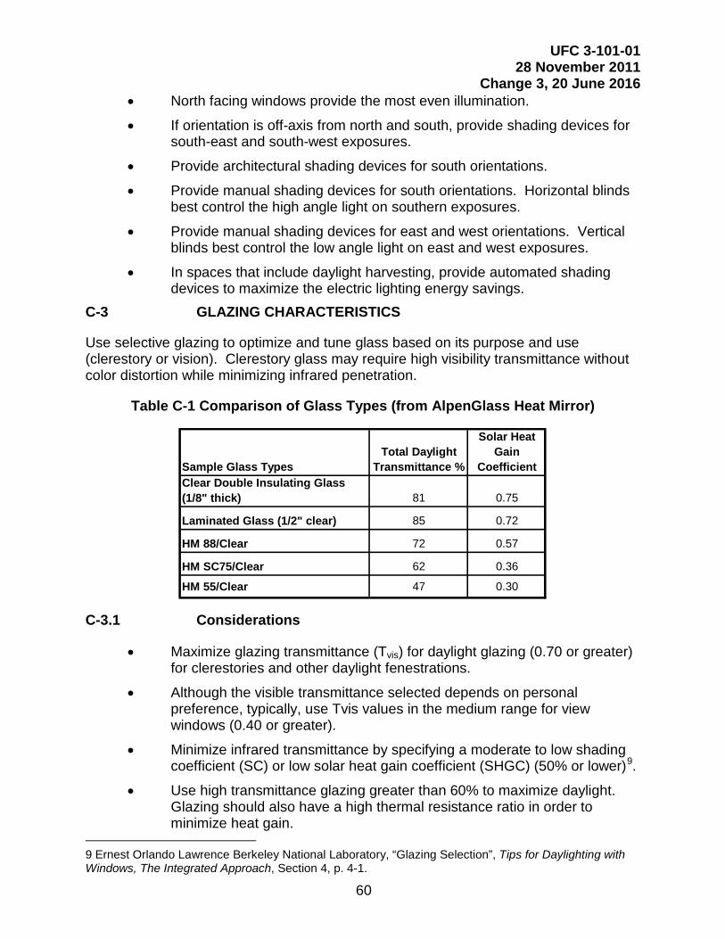
60
UFC 3-101-01 28 November 2011
Change 3, 20 June 2016
Sample Glass TypesTotal Daylight
Transmittance %
Solar Heat Gain
CoefficientClear Double Insulating Glass (1/8" thick) 81 0.75
Laminated Glass (1/2" clear) 85 0.72
HM 88/Clear 72 0.57
HM SC75/Clear 62 0.36
HM 55/Clear 47 0.30
• North facing windows provide the most even illumination.
• If orientation is off-axis from north and south, provide shading devices for south-east and south-west exposures.
• Provide architectural shading devices for south orientations.
• Provide manual shading devices for south orientations. Horizontal blinds best control the high angle light on southern exposures.
• Provide manual shading devices for east and west orientations. Vertical blinds best control the low angle light on east and west exposures.
• In spaces that include daylight harvesting, provide automated shading devices to maximize the electric lighting energy savings.
C-3 GLAZING CHARACTERISTICS
Use selective glazing to optimize and tune glass based on its purpose and use (clerestory or vision). Clerestory glass may require high visibility transmittance without color distortion while minimizing infrared penetration.
Table C-1 Comparison of Glass Types (from AlpenGlass Heat Mirror)
C-3.1 Considerations
• Maximize glazing transmittance (Tvis) for daylight glazing (0.70 or greater) for clerestories and other daylight fenestrations.
• Although the visible transmittance selected depends on personal preference, typically, use Tvis values in the medium range for view windows (0.40 or greater).
• Minimize infrared transmittance by specifying a moderate to low shading coefficient (SC) or low solar heat gain coefficient (SHGC) (50% or lower)9.
• Use high transmittance glazing greater than 60% to maximize daylight. Glazing should also have a high thermal resistance ratio in order to minimize heat gain.
9 Ernest Orlando Lawrence Berkeley National Laboratory, “Glazing Selection”, Tips for Daylighting with Windows, The Integrated Approach, Section 4, p. 4-1.

61
UFC 3-101-01 28 November 2011
Change 3, 20 June 2016
• Do not use tinted or mirrored coatings. Use clear glazing. C-4 QUANTITY OF GLAZING
Through simple tools and modeling, glazing quantities can be optimized in order to provide maximum daylight potential while minimizing economic costs. Bring daylight in high through clerestories and top-lighting, yet provide view windows for occupant benefits. Also, bring daylight in from two directions if possible for balanced, uniform lighting.
Toplighting optimization varies between 3% and 9% skylight to floor area ratio.10 The optimal amount of toplighting area factors in daylight contribution, cooling loads, and potential energy savings. In order to calculate toplighting area optimization, use a calculation program similar to “SkyCalc”11. Sunny climates with a cooling load dominated environment will require less toplighting than cooler overcast climates12.
10 New Buildings Institute, Inc. “Luminaires and Light Distribution, Daylight Systems”, Advanced Lighting Guidelines, Chapter 7. 2001 Edition, p. 7-31 11 The Heschong Mahone Group, “Optimizing Your Design”, Skylighting Guidelines, Ch1, 1998, p.1-1-5-7. 12 The Heschong Mahone Group, “Optimizing Your Design”, Skylighting Guidelines, Ch5, 1998, p. 5-12-13.

62
UFC 3-101-01 28 November 2011
Change 3, 20 June 2016
Figure C-5 Diagrams of Toplighting Strategies
a.
Vertical baffles block direct sunlight.
High reflectance surfaces redirect and diffuse sunlight.
Splay directs light and reduces contrast.
Horizontal Skylights with Splay
Vertical glass is shaded by overhang on south side.
No overhang required on north side.
Reflective roof directs light onto horizontal surface.
Roof Monitor
High reflectance surfaces redirect and diffuse sunlight.
Vertical glass is shaded by overhang.
Angled Clerestory

63
UFC 3-101-01 28 November 2011
Change 3, 20 June 2016
Figure C-6 Examples of Toplighting Applications
Figure C-7 Example of Clerestory Application

64
UFC 3-101-01 28 November 2011
Change 3, 20 June 2016
Figure C-8 Examples of Sidelighting Applications
Photograph: Eric Laignel C-4.1 Considerations
• Sidelighting windows should be located as high as possible since effective daylight penetration from windows is 1.5 times the height of the window13.
• Use high continuous clerestories for the deepest daylight penetration and uniformity.
• Provide glazing at eye level in order to provide exterior views,
• Use view windows that have minimal wall area between windows. Avoid small windows located in large wall areas because of the uncomfortable contrast and glare that result14.
• 1 sq ft (0.09 m2) of top lighting can provide illumination to about 10 times the area that sidelighting provides yet does not provide the view15.
• Space top lighting apertures approximately one and a half times the ceiling height for even illumination. Recess and splay (45º to 60º) skylights to minimize glare16.
• Toplighting systems located at least 1.5 times the mounting height on center can provide even daylight distribution.17
13 US Department of Energy, Energy Efficiency and Renewable Energy, “Sidelighting vs. Toplighting”, National Best Practices Manual, Daylighting and Windows, p. 73. 14 New Buildings Institute, Inc. “Luminaires and Light Distribution, Daylight Systems”, Advanced Lighting Guidelines, Chapter 7. 2001 Edition, p. 7-35. 15 US Department of Energy, Energy Efficiency and Renewable Energy, “Toplighting”, National Best Practices Manual, Daylighting and Windows, p. 75. 16 US Department of Energy, Energy Efficiency and Renewable Energy, “Design Details”, National Best Practices Manual, Daylighting and Windows, p. 101. 17 The Heschong Mahone Group, “Designing with Skylights”, Skylighting Guidelines, Chapter 2, 1998, pp. 2-5.

65
UFC 3-101-01 28 November 2011
Change 3, 20 June 2016
• Skylight area should be between 2% to 9% of the floor area depending on the climate optimization
C-5 GLARE AND CONTRAST CONTROL
Glare and excessive contrast occur when side and top lighting devices allow direct sunlight penetration. Quality daylighting allows skylight and only reflected sunlight to reach the task. Punched openings also can cause uncomfortable contrast ratios.
Figure C-9 Examples of Roof Shapes
Figure C-10 Example of Splayed Skylights
C-5.1 Considerations
• Coordinate external and internal shading with architect.
• Utilize top-lighting systems with vertical glazing to control direct radiation.
• If horizontal glazing is designed for top lighting systems, then provide splayed openings or translucent shielding below the skylight in order to minimize the contrast.

66
UFC 3-101-01 28 November 2011
Change 3, 20 June 2016
• Avoid punched windows; use continuous or mostly continuous side lighting.
• Use high reflectance surfaces for ceiling and walls (90% for ceilings and 60% for walls)18.
• Consider integrating use of automated window shading or dynamic glazing with the electric lighting control system to optimize the amount of daylight entering the space while minimizing the effects of solar heat gain and glare.
C-6 AUTOMATED SHADING
Automated shading should be considered in spaces utilizing daylight harvesting to preserve the functionality of the daylight harvesting system and maximize the energy savings of the system. The shades may be controlled to reduce glare and unwanted heat gain while still allowing natural light to enter the space. When utilizing automated shading the following may be considered:
• For ease of use the automated shades will be operated by common controls (i.e. same appearance and design) with the lighting control system.
• For maximum energy savings, the automated shading system should position the shades based on a combination of time of day, façade direction, and sky conditions.
• For maximum design flexibility and ease of installation, shade systems should have the capability to address each shade individually.
• The shading system may have a manual override that allows the occupant to temporarily adjust the shades to any desired position. The system will revert back to automatic control after a specified period of time.
• Based on the application and size of the windows or skylights, the shading system may employ drive (motor) technology that is either line-voltage or low-voltage in nature; an overall installed cost assessment of the shading system and the necessary equipment to integrate to the lighting control and building management systems may be done to determine the overall best value, installed cost solution for the project.
C-7 ACTIVE DAYLIGHTING
Active daylighting strategies and devices utilize a mechanical component to collect and distribute daylight. Such devices differ from the passive strategies that have previously been discussed which are stationary. The example shown in Figure C-14 turns a series of reflectors as the sun moves throughout the day. These reflectors catch the direct sunlight and redirect it through the skylight.
18 “Lighting for Offices”, Lighting Handbook Reference and Application, Chapter 32, Tenth Edition (New York: The Illuminating Engineering Society of North America, 2011), p. 32.23.

67
UFC 3-101-01 28 November 2011
Change 3, 20 June 2016
Such devices add extra initial cost and also pose additional maintenance issues. However, they also can make use of daylight for a longer period of time throughout the day. With tracking devices, effective daylighting can begin earlier in the morning and last later in the day than with stationary skylights.
Figure C-11 Example of an Active Daylighting System that Tracks the Sun and Directs Daylight into the Building.
C-7.1 Solar-adaptive shading
Another active daylight control technology is solar-adaptive window shading whereby shades automatically adjust throughout the day based on sky conditions or the sun’s location. This type of shading system blocks and reflects direct sunlight during the day to reduce solar heat gain and demand on the building’s air conditioning system. An example of solar-adaptive shading is shown in Figure C-15.
Figure C-12 Example of Solar-Adaptive Shading

68
UFC 3-101-01 28 November 2011
Change 3, 20 June 2016
C-8 PHYSICAL MODELING
Daylight levels depend on many factors such as window shapes, orientation, shading, and time of day. Therefore, physical models built to scale can provide information on light quality, shade, shadows, and actual light levels. By building the model with the actual proposed materials and orienting it with adjustments for latitude, season, and time of day, the light quality can be seen in the model. Such models inform the designer about quality issues including light patterns, shade, shadows, contrast, and penetration in the space. An illuminance meter inside the model will provide accurate predictions of expected light levels in the building.
C-9 COMPUTER SIMULATION
A wide range of software programs model the sun’s path and its impact on building geometry in addition to how it affects heat gain and energy use. In using any of the software, be aware of its limitations and assumptions, as well as the variables under the users’ control. These tools provide a prediction of how building components will behave throughout changing conditions. They do not provide actual light levels or energy use. The following web sites detail the features of some of these programs and their applications.
• US Department of Energy – Energy Efficiency and Renewable Energy Building Energy Software Tools Directory: http://www.eere.energy.gov/buildings/tools_directory/
• Whole Building Design Guide Energy Analysis Tools: http://www.wbdg.org/resources/energyanalysis.php
/1/

69
UFC 3-101-01 28 November 2011
Change 3, 20 June 2016
APPENDIX D GLOSSARY
D-1 ACRONYMS
AAMA American Architectural Manufacturer Association AC Articulation Class ACI American Concrete Institute ACP Architectural Compatibility Plan AF Air Force \1\ AFCEC Air Force Civil Engineer Center /1/ AFI Air Force Instruction AFIERA Air Force Institute of Environment, Safety, Occupational Health and Risk
Analysis AHJ Authority Having Jurisdiction AICUZ Air Installation Compatible Use Zones ANSI American National Standards Institute ASHRAE American Society of Heating, Refrigeration and Air Conditioning Engineers ASTM American Society of Testing and Materials BEAP Base Exterior Architecture Plan BIA Brick Industry Association BIM Building Information Modeling C Celsius CADD Computer-aided Design and Drafting CCB Construction Criteria Base CCD Customer Concept Document CFA Commission of Fine Arts CFR Code of Federal Regulations CID Comprehensive Interior Design CONUS Continental United States DDESB DoD Explosive Safety Board DoD Department of Defense E.O. Executive Order EFS Exterior Finish System EIFS Exterior Insulation Finish System EPA Environmental Protection Agency EPG Electronic Project Generator ETL Engineering Technical Letter F Fahrenheit FACD Functional Analysis Concept Development FEC Facilities Engineering Command FF&E Furniture, Fixtures & Equipment ft Foot or feet HQUSACE Headquarters, U.S. Army Corps of Engineers Hg Mercury

70
UFC 3-101-01 28 November 2011
Change 3, 20 June 2016
IAG Installation Architectural Guidelines IBC International Building Code ICD Intelligence Community Directive IESNA Illuminating Engineering Society of North America IHS Information Handling System IP Inch-pound in Inch or inches Kg Kilogram LCCA Life Cycle Cost Analysis m Meters mm Millimeters MAJCOM Major Command MPI Master Painters Institute NACE National Association of Corrosion Engineers NASA National Aeronautics and Space Administration NAVFAC Naval Facilities Engineering Command NCPC National Capital Planning Commission NCR National Capital Region NIST National Institute of Standards and Technology NOSSA Navy Ordnance Safety and Security Agency NRC Noise Reduction Coefficient OCONUS Outside Continental United States OMSI Operations and Maintenance Support Information OSHA Occupational Safety and Health Administration Pa Pascal (SI unit of pressure) PCAS Post-Construction Award Services psi Pound per square inch PTS Performance Technical Specifications PVC Polyvinyl Chloride QA/QC Quality Assurance/Quality Control RAMP Radon Assessment and Mitigation Program RFP Request for Proposal SCIF Sensitive Compartmented Information Facility SDSFIE Spatial Data Standard for Facilities, Infrastructure and Environment sf square feet SHGC Solar Heat Gain Coefficient SI Le Système International d'Unités/International System of Units (Metric
System) SID Structural Interior Design sm square meters SMACNA Sheet Metal and Air Conditioning Contractors’ National Association SPF Spray Polyurethane Foam STC Sound Transmission Coefficient UFC Unified Facilities Criteria UFGS Unified Facilities Guide Specifications USACE U.S. Army Corps of Engineers USGBC U.S. Green Building Council

71
UFC 3-101-01 28 November 2011
Change 3, 20 June 2016
VECP Value Engineering Change Proposal VT Visible Transmittance WBDG Whole Building Design Guide w.g. water gauge (IP unit of pressure) WRB Water Resistant Barrier

72
UFC 3-101-01 28 November 2011
Change 3, 20 June 2016
D-2 DEFINITION OF TERMS
Air Barrier. The term “air barrier” refers to the “prescriptive continuous air barrier” for the “opaque building envelope” specified by Normative Appendix B of ASHRAE 189.1.
Building System and Subsystems. An assembly of dimensionally and functionally pre-coordinated subsystems which, when combined, produces an essentially complete building. A subsystem is one of many building components designed and manufactured to be integrated with other subsystems to produce an entire building system.
Building Information Model (BIM). A BIM is a digital representation of physical and functional characteristics of a facility. As such it serves as a shared knowledge resource for information about a facility forming a reliable basis for decisions during its lifecycle from inception onward. \1\
Noise Isolation Class (NIC). NIC is a method for field transmission ratings. The higher the number the better the noise control. NIC rates a partition's ability to block airborne noise transfer. NIC testing is preferable to STC testing as it is specified on more specific space types (such as spaces with operable walls, unaccompanied housing sleeping rooms to each other or to the adjacent corridor, and the actual work spaces in administration facilities). For a field STC test, the individual transmission loss measurements are modified based upon the reverberation time, the size of the room, and the size of the tested partition. The NIC does not include these modifications and simply measures the transmission loss between 125 and 4,000Hz. The value of this rating is that it better tests the performance of the assembly in the field, though it is highly dependent on field conditions of the tested space.
Outdoor-Indoor Transmission Class (OITC). OITC is defined as the A-weighted sound level reduction of a test specimen (or a space) in the presence of an idealized mixture of transportation noises; aircraft takeoff, freeway, and railroad pass by. It assigns a single number rating to measure Sound Transmission Loss (TL) data obtained in accordance with ASTM E-90. The higher the number the better the control.
Sound Transmission Class (STC). STC is a single number developed under laboratory conditions that represents the effectiveness of materials or construction to retard the transmission of air-borne sound. It is not as effective for measurement in low frequency noise sources such as mechanical equipment.
/1/