unified facilities criteria (ufc) - navfac...
TRANSCRIPT

FINAL DRAFT UFC 4-420-01 December 2004
UNIFIED FACILITIES CRITERIA (UFC)
FINAL DRAFT DESIGN: AMMUNITION AND
EXPLOSIVE STORAGE MAGAZINES
APPROVED FOR PUBLIC RELEASE; DISTRIBUTION UNLIMITED

DRAFT UFC 4-420-01 December 2004
UNIFIED FACILITIES CRITERIA (UFC)
DRAFT DESIGN: AMMUNITION AND EXPLOSIVE STORAGE MAGAZINES Any copyrighted material included in this UFC is identified at its point of use. Use of the copyrighted material apart from this UFC must have the permission of the copyright holder. U.S. ARMY CORPS OF ENGINEERS NAVAL FACILITIES ENGINEERING COMMAND (Preparing Activity) AIR FORCE CIVIL ENGINEER SUPPORT AGENCY Record of Changes (changes are indicated by \1\ ... /1/) Change No. Date Location

DRAFT UFC 4-420-01 December 2004
1
FOREWORD The Unified Facilities Criteria (UFC) system is prescribed by MIL-STD 3007 and provides planning, design, construction, sustainment, restoration, and modernization criteria, and applies to the Military Departments, the Defense Agencies, and the DoD Field Activities in accordance with USD(AT&L) Memorandum dated 29 May 2002. UFC will be used for all DoD projects and work for other customers where appropriate. All construction outside of the United States is also governed by Status od forces Agreements (BIA.) Therefore, the acquisition team must ensure compliance with the more stringent of the UFC, the SOFA, the HNFA and the BIA, as applicable. UFC are living documents and will be periodically reviewed, updated, and made available to users as part of the Services’ responsibility for providing technical criteria for military construction. Headquarters, U.S. Army Corps of Engineers (HQUSACE), Naval Facilities Engineering Command (NAVFAC), and Air Force Civil Engineer Support Agency (AFCESA) are responsible for administration of the UFC system. Defense agencies should contact the preparing service for document interpretation and improvements. Technical content of UFC is the responsibility of the cognizant DoD working group. Recommended changes with supporting rationale should be sent to the respective service proponent office by the following electronic form: Criteria Change Request (CCR). The form is also accessible from the Internet sites listed below. UFC are effective upon issuance and are distributed only in electronic media from the following sources: • Unified Facilities Criteria (UFC) Index http://65.204.17.188//report/doc_ufc.html. • USACE TECHINFO Internet site http://www.hnd.usace.army.mil/techinfo/index.htm. • NAVFAC Engineering Innovation and Criteria Office Internet site http://dod.wbdg.org/. • Construction Criteria Base (CCB) system maintained by the National Institute of Building
Sciences at Internet site http://www.ccb.org/. Hard copies of UFC printed from electronic media should be checked against the current electronic version prior to use to ensure that they are current. AUTHORIZED BY: ______________________________________ JAMES C. DALTON, P.E. Chief, Engineering and Construction Division U.S. Army Corps of Engineers
______________________________________JOSEPH E. GOTT, P.E. Chief Engineer Naval Facilities Engineering Command
______________________________________ PAUL A. PARKER, P.E. The Deputy Civil Engineer DCS/Installations & Logistics Department of the Air Force
______________________________________Dr. GET W. MOY, P.E. Director, Installations Requirements and Management Office of the Deputy Under Secretary of Defense (Installations and Environment)

DRAFT UFC 4-420-01 December 2004
2
CONTENTS
Page
CHAPTER 1 INTRODUCTION Paragraph 1-1 PURPOSE AND SCOPE ................................................................... 1-1
1-2 BACKGROUND ................................................................................. 1-1 1-3 APPLICABILITY ................................................................................. 1-2 1-4 CONFLICTS ...................................................................................... 1-2 1-5 REFERENCES .................................................................................. 1-2
1-6 WAIVERS AND EXCEPTIONS 1-2 CHAPTER 2 PLANNING CRITERIA Paragraph 2-1 MAGAZINE TYPES .................................................................. 2-1 2-1.1 Earth-Covered Magazines ........................................................ 2-1
2-1.2 Aboveground Magazines .......................................................... 2-1 2-.2 SITING CONSIDERATIONS .................................................... 2-1 2-2.1 Magazines as Potential Explosion Sites (PES) ....................... 2-2 2-2.2 Magazines as Exposed Sites (ES) .......................................... 2-2 2-2.3 Barricades ................................................................................ 2-3 2-3 APPROVAL CONSIDERATIONS ............................................. 2-3 2-3.1 Magazine Design Approval ....................................................... 2-4 2-3.2 Approved Magazine Designs .................................................... 2-4 2-3.3 Other Existing Magazine Designs............................................. 2-5 2-3.4 Magazine Construction and Explosives Safety Site Approval .. 2-6 2-4 MAGAZINE DESIGN SELECTION CONSIDERATIONS .......... 2-6 2-4.1 Net Explosive Weight (NEW) Limits ......................................... 2-6 2-4.2 Magazine Characteristics ......................................................... 2-6 2-4.3 Storage and Loading Plans ...................................................... 2-7
CHAPTER 3 DESIGN CRITERIA 3-1 EARTH COVER........................................................................ 3-1 3-2 FLOOR LOADING .................................................................... 3-1 3-3 FOUNDATIONS ....................................................................... 3-1 3-4 WATERPROOFING AND DRAINAGE ..................................... 3-2 3-5 VENTILATION .......................................................................... 3-2 3-6 TEMPERATURE AND HUMIDITY CONTROLS ....................... 3-2 3-7 SUBSTANTIAL DIVIDING WALL ............................................. 3-2 3-8 PHYSICAL SECURITY ............................................................. 3-2 3-9 CATHODIC PROTECTION ...................................................... 3-3 3-10 LIGHTNING PROTECTION ...................................................... 3-3 3-11 GROUNDING ........................................................................... 3-3 3-12 ELECTRICAL HAZARDOUS CLASSIFICATION ...................... 3-4 3-13 INTERIOR ELECTRICAL DESIGN ..................................... 3-4 3-14 DoD AND SERVICE-SPECIFIC EXPLOSIVE ......................... 3-4 SAFETY CONTACTS

DRAFT UFC 4-420-01 December 2004
3
GLOSSARY ACRONYMS ……………………………………………… Glossary-1 DEFINITIONS ……………………………………………. Glossary-1 APPENDIX A REFERENCES ................................................................................ A-1 APPENDIX B TYPES OF ECM IN USE..………………………… ............ ……B-1 APPENDIX C “7-BAR” AND “3-BAR” ECM APPROVED FOR NEW CONSTRUCTION (IP Units) .......................................................... C-1
FIGURES Figure Title C-1 RC Box, Type ‘C’ (SI Units) ....................................................................... D-4 C-2 RC Box, Type ‘D’ and RC Box, Type ‘D’ (HSILS) (SI Units) ..................... D-5 C-3 RC Box Type ‘E’ (SI Units) ........................................................................ D-6 C-4 RC Box Type ‘F’ (SI Units) ........................................................................ D-7 C-5 RC Box Type ‘M’ (SI Units) ....................................................................... D-8 C-6 RC Box (421-80-06) Modified (SI Units) ................................................... D-9 C-7 RC Box (MLH) 180B (SI Units) ................................................................. D-10 C-8 RC Box (MSM) (SI Units) .......................................................................... D-11 C-9 RC Box (Multi-Cell) (SI Units) .................................................................... D-12 C-10 RC Circular Arch (SI Units) ...................................................................... D-13 C-11 RC Arch (421-80-05) (SI Units) ................................................................. D-14 C-12 RC FRELOC Stradley (33-15-74) (SI Units) .............................................. D-15 C-13 Steel Oval Arch (421-80-03) (SI Units) ..................................................... D-16 C-14 Steel Semi-Circular Arch (421-80-01) (SI Units) ....................................... D-17 C-15 Composite Circular Arch (SI Units) ........................................................... D-18 C-16 Composite Oval Arch (SI Units) ................................................................ D-19

DRAFT UFC 4-420-01 December 2004
4
CHAPTER 1
INTRODUCTION 1-1 PURPOSE AND SCOPE. This UFC serves as a reference tool to assist in the planning and/or design of Ammunition and Explosive (AE) storage magazines for the Department of Defense (DoD), by providing definitions and information related to the design, selection, and siting of these unique facilities. This UFC is intended to assist in the selection of a magazine design by providing available options and information related to the use of designs that have been used in the past and have been approved by the DDESB. The individual DoD services canmay also provide additional guidance on the selection of magazine designs. A web site designed to be a companion resource to this UFC is located on the Whole Buildings Design Guide and can be accessed at: http://www.wbdg.org/design/index.php?cn=1.3&cx=0. This web site provides the following additional information and resources:
available electronic copies of referenced codes and standards, available design drawings, approval letters, and specifications for “7-Bar” and “3-
Bar” Earth-Covered Magazines (ECM) that have been approved for new construction,
available drawings and related information for the designs of “7-Bar” and “3-Bar” ECM that are no longer approved for new construction but still in use,
available drawings and related information for the designs of ECM and Aboveground magazines (AGM) and containers that have been approved for restricted use,
a listing of the existing magazine designs that are classified as undefined, and thus are not approved for new construction,
available drawings for barricade design utilizing various construction materials, and
links to additional related resources and publications. This UFC, when used with the companion web site, provides planners and designers of AE storage facilities access to up to date available information and resources needed in the selection and design of new storage magazines and in the evaluation of existing facilities. 1-2 BACKGROUND. The Department of Defense Explosives Safety Board (DDESB) has established uniform minimum AE safety standards for personnel and property that have the potential of being exposed to the effects of an accidental explosion. These standards govern the design, construction, and use of all AE storage facilities within the Department of Defense.

DRAFT UFC 4-420-01 December 2004
5
Magazines are used to store AE materials. Magazines aremay be defined as AGM or ECM; 7-Bar, 3-Bar, or Undefined. DoD explosives safety standards are contained in DoD 6055.9-STD, DoD Ammunition and Explosives Safety Standards. The latest version of this document can be obtained at http://www.dtic.mil/whs/directives/corres/pdf/p60559std_100504/p60559s.pdf, or the DDESB web site http://www.ddesb.pentagon.mil/. Service-specific explosive safety standards that implement the DoD standards are contained in the following documents:
DoD Contractors: DoD 4145.26-M, DoD Contractors’ Safety Manual for Ammunition and Explosives
Air Force: AFM 91-201, Explosives Safety Standards Army: AR 385-64, U.S. Army Explosives Safety Program,
DA PAM 385-64, Ammunition and Explosives Safety Standards Navy: NAVSEA OP 5 Volume 1, Ammunition and Explosives Safety Ashore
1-3 APPLICABILITY. This UFC applies to all service elements and contractors involved in the planning, design, and construction of AE storage facilities worldwide. The source for table C-1 is table AP-1 of DDESB TP-15. This table and the accompanying notes identify additional limitations, restrictions, or conditions associated with the use of these designs. 1-4 CONFLICTS. This UFC and the companion web site supplement the information contained in the DoD and service-specific explosive safety standards, and in the DDESB publications and memorandums. In the event of conflict or disagreement, the DoD and service-specific explosive safety standards and the DDESB documents govern. All apparent conflicts must be brought to the attention of the authorizing design agency for additional guidance as necessary. 1-5 REFERENCES. Appendix A contains a list of references used in this UFC.
1-6 WAIVERS AND EXCEPTIONS. For Waiver and Exception policy and guidelines refer to the DoD and service specific explosive safety standards.

DRAFT UFC 4-420-01 December 2004
6
CHAPTER 2
PLANNING CONSIDERATIONS 2-1 MAGAZINE TYPES AE storage magazines are classified as either Covered Magazines (ECM) or Aboveground Magazines (AGM). Magazines are considered uninhabited structures and there do not require a mass notification system and according to UFC 3-600-01, a fire suppression system and a fire alarm system are not required 2-1.1 Earth-Covered Magazines. . Within DoD, ECM’s are classified based upon their structural strength and corresponding ability to withstand blast loadings. Siting criteria based on the ECM classification are applied to ensure a consistent level of protection regardless of the classification. DoD 6055.9-STD defines three basic ECM classifications: "7-Bar", "3-Bar" and Undefined. These classifications are based primarily on the relative strength of the magazine headwall and doors. Design criteria for each of the ECM classifications has been established and can be found in DoD 6055.9-STD. The DDESB has classified previously designed ECM and summarized protective construction designs in Technical Paper TP-15, Approved Protective Construction. In general, ECM are magazines with a minimum of 2’-0” ( 0.61 m) earth cover. Typical features of ECM are described in Appendix B. Appendix C provides general descriptions of the physical properties of several of the different ECM types that have been used in the past. [Note: One exception to this is the “High-Performance” Magazine (HPM) concept design that is technically not earth covered. However it is considered to be equivalent to a “7-Bar” ECM.] 2-1.1.1 “7-Bar” (Standard) ECM. A “7-Bar” ECM provides the highest resistance to blast loading. Magazines classified as “7-Bar” were referred to as “Standard” magazines prior to 1997. 2-1.1.2 “3-Bar” ECM. A “3-Bar” ECM provides a lower level of resistance to blast loading than a “7-Bar” ECM, but more than an Undefined ECM. In 1997, this classification was established as an intermediate classification between the former classifications of “Standard” and “Non-standard”. 2-1.1.3 Undefined (Non-Standard) ECM. An Undefined ECM has not been shown by analysis or testing to be capable of providing a level of resistance equivalent to either a “7-Bar” or “3-Bar” ECM. Magazines classified as Undefined were referred to as “Non-standard” magazines prior to 1997. 2-1.2 Aboveground Magazines. All above grade magazines that are not earth covered are considered AGM. This also includes storage pads for AE. [Note: One exception to this is the HPM concept design that is technically not earth covered. However due to its design, it is considered to be equivalent to a “7-Bar” ECM.] 2-2 SITING CRITERIA. To ensure the prevention of unacceptable damage or

DRAFT UFC 4-420-01 December 2004
7
injuries in the event of an accidental explosion, siting criteria have been established to define minimum required separation distances between a Potentia Explosion Site (PES) and other facilities. The minimum separation distances, commonly referred to as explosives safety Quantity-Distance (QD), are based upon several factors including
• The level of protection mandated by the applicable explosive safety standard. • The ES type and classification. • The net explosive weight (NEW). • The hazard classification of the AE at a PES. • The physical orientation between the PES and the Exposed Site (ES). • The potential presence of effective barricading.
Minimum explosives safety QD relationships are defined in the applicable DoD and service-specific explosive safety standards for various applications. These relationships are based on maximum levels of risk considered acceptable for various types of ES. Separation distances are not absolute safe distances, but are relative protective or safe distances. Use greater distances than those shown in the explosive safety standards whenever practicable. Explosives safety site plans are required for construction projects involving new facilities (explosive or non-explosive) within QD arcs of existing PES, as well as for the upgrading or renovation of existing facilities (explosive or non-explosive), that might be impacted by explosives safety criteria (e.g., hardening for fragmentation or blast, intermagazine separation, explosive safety QD). These site plans reviews allow for a higher-level of evaluation to insure explosives safety criteria are being met by the proposed work. DoD requires certain explosives safety site plans to be forwarded to the DDESB for review and approval. Each Service provides guidance as to what level of site planning review and approval must be accomplished prior to commencing projects. 2-2.1 Magazines as Potential Explosion Sites (PES). DoD 6055.9-STD defines minimum explosive safety QD relationships between a magazine as a PES and surrounding ES including other magazines, operating buildings, inhabited buildings, and public traffic routes to ensure uniform minimum explosive safety standards for DoD facilities. As a PES, all classifications of ECM are considered the same. In general, the required separation distances are generally greater from an AGM than an ECM. 2-2.2 Magazines as Exposed Sites (ES). Minimum explosive safety QD relationships have been established between a PES and a magazine as an exposed site. Tables specifying minimum QD requirements can be found in the DoD and Service explosives safety documents. In general, required separation distances are greater for an AGM than for an ECM. For ECM, required separation distances are generally greater for a “3-Bar” ECM than a “7-Bar” ECM and greater still for an Undefined ECM. The minimum explosive safety QD relationship between magazines is commonly referred to as the intermagazine distance (IMD). The required IMD is dependent on
• The physical orientation of the magazines.

DRAFT UFC 4-420-01 December 2004
8
• The structural classification of the each magazine as an ES. • The NEW and type of AE within each magazine as a PES. • The potential presence of an effective barricade.
Certain “7-Bar” ECM have approved NEW limits that are less than the 500,000 lbs (226,800 kg) typically assigned to a “7-Bar” (Standard) ECM. This is because ECM are approved on the basis of their ability to withstand an external explosion acting as an ES. For example, a “7-Bar” ECM approved for 350,000 lbs (158,760 kg) of Hazard Division (HD) 1.1; such as the RC Box Type ‘F’ ECM; would provide “7-Bar” protection from the effects of an external explosion from a PES containing 350,000 lbs (158,760 kg) and separated by the appropriate “7-Bar” IMD. The RC Box Type ‘F’ ECM will not provide “7-Bar” protection to its contents from an explosion of more than 350,000lbs (158,760 kg), unless the separation distance is increased and it can be demonstrated that the effects of an explosion of the PES will not exceed the effects of an explosion of 158,760 kg (350,000 lbs) NEW at the IMD. A very common situation found in military installations usually involves a large number of ECM’s with no designation. Using available structural drawings and the 3-bar or 7-bar load indicated in DoD 6055.9-STD, we can analyze the ES ECM under the 30bar or 7-bar load with a reduced capacity in the PES (less than 500,000 lbs). if the deformation criteria is met, then the ES could obtain a 3-bar or 7-bar structural designation with the corresponding reduced capacity. An additional advantage is that loading this information in siting computer programs such as ASHS, allows the installation to determine more efficient separation distances for future storage construction. The tables provided in the Appendices C identify the NEW rating of magazines and containers approved for new construction. 2-2.3 Barricades. Barricades are used to decrease the required minimum separation distances between magazines and between magazines and ordnance operating buildings. . Specific requirements on the design and siting of barricades as well as the reduction in the minimum separation distance resulting from a properly sited and constructed barricade are provided in the DoD and service-specific explosive safety standards. Army Definitive Drawing 149-30-01 illustrates several conceptual barricade designs utilizing various construction materials. When properly sited and constructed barricades offer protection against high-velocity, low angle fragments and reduced blast over pressures immediately behind the barricade. They do not offer protection against high angle fragments and are ineffective in reducing blast overpressures at distance from the barrier. To be effective in reducing low angle fragments barricades must be high and wide enough to intercept the ballistic trajectories of the fragments and thick enough to reduce the fragment velocity to acceptable limits.

DRAFT UFC 4-420-01 December 2004
9
Earth cover on the sides and rear of an ECM qualifies as barricaded if the cover depth and slope requirements are met and the application of barricaded distance is allowed for the situation being considered. DoD 6055.9-STD provides specific permissible exposures where barricaded distances are permitted from an ECM to an explosives operating location. 2-3 SITE AND DESIGN APPROVALS. Site and construction plans for AE storage facilities must be approved by the DDESB or the service-specific safety organizations to ensure that the minimum DoD and service-specific explosive safety standards have been addressed. An exception to this allows the approval of service specific safety organizations for security and limited amounts of ammunition without DDESB approval. Situations requiring approval include, but are not limited to:
New construction or major modification of facilities either involved in AE operations or in proximity to AE operations so as to be potentially exposed to hazards and
Changes in the utilization of facilities that couldmay affect the minimum required explosive safety QD relationships.
Specific guidelines and procedures for approval of site and construction plans are contained in the DoD and service-specific explosive safety standards. Plans must be approved prior to commencing construction. 2-3.1 Magazine Design Approval. The design for all new AE storage magazines must be reviewed and approved by the DDESB to ensure that minimum explosive safety standards have been addressed. For a magazine to be sited within the explosive safety QD relationships corresponding to approved “7-Bar” and “3-Bar” ECM, it must be demonstrated that the design will provide the corresponding level of protection against unacceptable damage or injury. The approval of a “7-Bar” or “3-Bar” ECM requires the submission of test results and/or detailed structural calculations. Prior to the start of a design, it is essential to closely coordinate the requirements with the DDESB to avoid excessive problems and delays in completing the design and obtaining the necessary approvals. Once a “7-Bar” and “3-Bar” ECM design has been approved by the DDESB, the design does not have to be reapproved for subsequent uses. New Undefined ECM and AGM designs require DDESB or the service-specific safety organizations to ensure that the minimum DoD and service-specific explosive safety standards have been addressed and to ensure that they comply with minimum design and construction criteria, including earth cover depth and slope, grounding, and lightning protection. An exception to this allows the approval of service specific safety organizations for security and limited amounts of ammunition without DDESB approval 2-3.2 Approved Magazine Designs. To facilitate the design and approval

DRAFT UFC 4-420-01 December 2004
10
process for AE storage magazines several approved designs have been developed for “7-Bar” and “3-Bar” ECM and for magazines and containers approved for restricted use. Appendices B and C include a listing and basic description of “7-Bar” and “3-Bar” ECM designs approved for new construction. Appendix C includes a listing of magazines and containers with reduced NEW and/or reduced explosive safety QD that are approved for use with restrictions. The most current construction drawings, approval letters, and additional information and notes related to the approved designs can be accessed at the following web site: http://www.wbdg.org/design/buildingtypes.php . The source for tables DC-1 are tables AP1-1 of DDESB TP-15. These tables and the accompanying notes identify additional limitations, restrictions, or conditions associated with the use of these designs. Approved designs can be site-adapted or tailored to the requirements of a specific site. Site specific adaptation primarily involves minor modifications to the foundation and the drainage systems to suit local soil and site characteristics. In addition, certain AE magazines may require additional consideration for utilities, security, electrical, grounding, or humidity and temperature limits. Any changes to the approved designs, other than minimal site adaptation, that may affect the explosive safety of a magazine design must be approved by the appropriate service-specific explosive safety office and the DDESB prior to construction. 2-3.3 Other Magazine Designs. 2-3.3.1 “7-Bar” and “3-Bar” ECM Designs no Longer Approved for New Construction. The Whole Building Design Group web site and DDESB TP-15, Table 1-2 contains a listing of ECM designs that have been previously approved for “7-Bar” or “3-Bar” siting but are no longer approved for new construction. In most cases, these designs have not been updated to satisfy criteria changes. The primary intent of this list is to assist activities in siting additional magazines. NEW limitations and/or restrictions associated with their DDESB approval must be observed. These designs maycan be used as the basis for new ECM designs, but they must not be used for construction until they are updated to comply with current explosive safety requirements, current construction methods and criteria, and are reviewed and approved by the DDESB. Any updated design drawings must clearly identify all changes and revisions made to the original design prior to approval. Available electronic drawings, approval letters, and additional information and notes related to the approved designs can be accessed at the following web site: http://www.wbdg.org/design/buildingtypes.php . 2-3.3.2 Undefined ECM Designs. DDESB TP-15, Table AP1-3 contains a listing of ECM designs that are classified as undefined. These designs have not been shown by analysis or testing to have the structural capacity of either a “7-Bar” or “3-Bar” ECM.

DRAFT UFC 4-420-01 December 2004
11
An undefined ECM can be structurally analyzed in accordance with the Joint Service Manual Army TM5-1300/NAVFAC P-397/AFR 88-22, Structures to Resist the Effects of Accidental Explosions, to determine its structural capabilities and potentially upgrade the classification. HNDED-CS-93-4, Guide for Evaluation Blast Resistance of Nonstandard Magazines, illustrates procedures that can be used to determine the adequacy of the headwall and doors of an existing ECM to provide an acceptable level of protection from a given quantity of explosive at a known distance. The DDESB must review and approve the structural analysis and ensure that the design complies with current explosive safety requirements as well as current construction methods and criteria, prior to reclassifying the ECM design. Table AP1-3 of DDESB TP-15 includes a listing of Undefined ECM designs. This table and the accompanying notes identify additional limitations, restrictions, or conditions associated with the use of these designs. 2-3.4 Magazine Construction and Explosives Safety Site Approval. The explosive safety site plan for all new AE storage magazines must be reviewed and approved by the DDESB and the applicable service-specific explosive safety representative to ensure that the magazine has been sited in accordance with the minimum explosive safety QD appropriate to the magazine type and classification. An exception to this allows the approval of service specific safety organizations for security and limited amounts of ammunition without DDESB approval If only approved magazine designs are used in a project, and the designs have not been changed other than for minimal site adaptation, only the project site plan along with the core drawing numbers of the approved magazine design selected for construction must be submitted for site approval 2-4 MAGAZINE SELECTION CONSIDERATIONS. Selection of the most suitable magazine design to use at a given site will depend on a number of factors including, but not limited to, the hazard classification and quantity of AE that is anticipated to be stored in the magazine, the cost of construction and maintenance, siting limitations or restrictions, ordnance storage and delivery operations, flexibility for future revisions to operations or mission, and AE non-compatibility. Some of these factors are discussed below. The use of an approved standard designs for new magazine construction is mandatory within the DoD except where a preapproved design is not suitable due to special circumstances. 2-4.1 Net Explosive Weight (NEW) Limits. Each of the approved magazine standard designs is rated for a maximum quantity of HD 1.1 AE that can be stored, expressed as maximum NEW. A magazine is sited using explosive safety QD relationships corresponding to the maximum amount of NEW that will be stored within the magazine. However the quantity of AE stored must never exceed the maximum rated value.

DRAFT UFC 4-420-01 December 2004
12
2-4.2 Magazine Characteristics. 2-4.2.1 Shapes and Sizes. Some ECM shapes that have been used in the past are shown in appendix C. The physical dimensions and shapes of “7-Bar” and “3-Bar” ECM designs approved for new construction are provided in Tables C-1 and are graphically depicted in Appendx C. Some approved ECM designs allow variable lengths to provide greater flexibility in sizing a magazine to its specific intended use. 2-4.2.2 Door Openings. The approved “7-Bar” and “3-Bar” magazine designs have various door opening sizes. To minimize construction cost, the door opening shall be the smallest necessary to accommodate the size of packaged AE to be stored and the anticipated delivery and storage methods. Size openings to accommodate anticipated future requirements. 2-4.2.3 Door Types. Magazine doors are vertical swinging or sliding type. Doors are either manually or electrically operated. The HPM concept design has electrically operated horizontal sliding doors that cover the top of the AE storage compartments. 2-4.2.4 Storage Options. AE is stored within a magazine utilizing forklifts. An overhead bridge crane storage option has been developed in the RC Box, Type “M” magazine. The HPM concept design requires the use of an overhead bridge crane for storage and retrieval of AE. 2-4.2.5 Land Availability Constraints. The HPM concept design was developed to accommodate storage of relatively large amounts of AE at sites that are restricted due to land availability or neighboring site development. This magazine consists of a group of isolated compartments designed to prevent the propagation of an explosion between compartments. Thus siting of the HPM concept design is based on the maximum credible event (MCE) in a single compartment as opposed to the total quantity of AE in all compartments of the magazine. 2-4.3 Storage and Loading Plans. AE packaging information and suggested storage loading plans have been developed for many of the approved magazine designs. These plans are to assist in the effective use of magazines and may be used to estimate the potential storage capacity of various types of ordnance within a given magazine. The U.S. Army Material Command provides Storage and outloading drawings for various AE within certain ECMs. These drawings, 19-48-75-5, may be obtained at the Defense Ammunition Center web site: https://www3.dac.army.mil/DET/order/draworder.html. Additional standard layout plans for palletized ammunition, missiles and torpedoes within ECMs are provided in NAVSEA Instruction 8024.2, Magazine Stowage Layout

DRAFT UFC 4-420-01 December 2004
13
Standards.

DRAFT UFC 4-420-01 December 2004
14
CHAPTER 3
DESIGN CONSIDERATIONS AND REQUIREMENTS 3-1 EARTH COVER. The minimum earth cover over the top of a magazine shall be 2’-0” (0.61m). The maximum slope must be maintained at 2 horizontal to 1 vertical unless means are provided to control erosion. The earth cover above, to the sides, and to the rear of a ECM is the critical element of its design. The material for the earth cover shall be reasonably cohesive material, and must be free from deleterious organic matter, trash, debris, and stones heavier than 10 pounds or larger than 6 inches in diameter. Solid or wet clay should not be used due to its excessive cohesiveness. Limit larger stones to the lower center of fills and do not use for earth cover over the magazines. Compact the material and prepare as necessary to maintain structural integrity and provide erosion control. In locations where it is impossible to use a cohesive material or where rainfall is insufficient to maintain a grass cover, use other suitable materials and stabilization methods to ensure the structural integrity of the cover. The HPM concept design is considered to be the structural equivalent of a “7-Bar” ECM in terms of protecting the stored ordnance by preventing propagation of an explosion that couldmay occur in an adjacent magazine. This concept design uses earth berms on the exterior walls but utilizes lightweight reinforced concrete covers in lieu of an earth cover over the top of the ordnance storage area. 3-2 FLOOR LOADING. The design floor live load shall be the maximum anticipated loading of stored material within the magazine during its useful life. Considerations shall also be given to wheel loading from weight handling equipment (especially large or side loading vehicles). Floor live loading as shown on the Standard Approved Magazine Drawings is based upon the anticipated maximum loading for that particular magazine type. Where soil conditions are poor, the design floor live loading may be reduced if it can be demonstrated that a reduced floor loading will be acceptable at a give location based on the actual anticipated usage. In such case, the maximum design floor live loading shall be prominently posted at the entrance and within the magazine structure. Under all cases, the minimum floor live loading for any magazine type shall be 500 PSF. 3-3 FOUNDATIONS. Foundations shall be provided with a safe working static load capacity equivalent to or greater than the safe working static load capacity of the foundation shown on the Standard Approved Magazine Drawings. Foundations for earth retention walls shall be designed using conventional design methods. Foundations that support elements of the magazine that are required to resist dynamic incident pressures from an external explosion from a PES shall have an ultimate dynamic load capacity equivalent or greater to the ultimate dynamic load capacity of the foundations shown on the Standard Approved Magazine Drawings. Elements of the magazine that are required to resist the loading from a PES typically include structural walls and columns supporting roof elements. Unless a more detailed analysis is warranted, it is recommended that foundations redesigned for poor soil conditions shall have a safe working static load capacity equal to or greater that the safe working load capacity of

DRAFT UFC 4-420-01 December 2004
15
the foundations of the Standard Approved Magazine Drawings 3-4 WATERPROOFING AND DRAINAGE. Ensure that the magazine is watertight and offers adequate protection to the stored AE from water intrusion. An elastomeric membrane is appropriate for concrete magazines and a bituminous waterproofing is more suitable for steel magazines. Protect the waterproofing membrane from backfilling and compaction operations during construction. (Note: The Navy currently has a prohibition against the use any types of steel ECM’s for new construction due to difficulty of properly waterproofing these magazines.) Provide a drainage system around the ECM to adequately channel the water away from the structure. 3-5 VENTILATION. Typically, ECMs contain some form of ventilation. This is usually accomplished by louvered openings in the headwall and ventilator stacks that exit through the rear wall and penetrate through the earth cover. The HPM concept design requires additional forced ventilation considerations in the ordnance storage compartments. 3-6 TEMPERATURE AND HUMIDITY CONTROLS. Most AE do not require temperature or humidity controls beyond standard ventilation. However, some specialized missiles have restrictions on the temperature and humidity at which they can be stored. At some locations, these restrictions will necessitate ADDITIONAL temperature and humidity controls within the magazines. When adding equipment or openings to an approved magazine design, the addition must not affect the rating or the explosive safety aspects of its design; such as lightning protection, structural integrity, etc. Changes to approved designs must be reviewed and approved by the service-specific explosive safety office and the DDESB prior to construction. Design of temperature and humidity control systems shall be in accordance with UFC 3-400-10N. 3-7 OPTIONAL SUBSTANTIAL DIVIDING WALL. A Substantial Dividing Wall (SDW) is used to prevent prompt detonation reactions or propagation of burning reactions involving AE between adjacent bays within a magazine and to provide personnel protection from remotely controlled operations. DDESB-KT memorandum of 15 January 2003 provides updated guidance on the usage, applicability and limitations of a SDW. If the SDW guidance is adhered to, the NEW of each room or cubicle can be considered independently for the purpose of establishing minimum explosive safety QD relationships as described in the DDESB-KT memorandum. 3-8 PHYSICAL SECURITY. The approved magazine standard designs only identify limited physical security features. The designs include a high security hasp on the doors, steel bars at openings, and couldmay also include conduit for electronic security systems. Security requirements for a specific magazine must be determined by the using agency and the installation security personnel. Minimum DoD physical security standards and criteria are contained in DoD 5100.76-M,

DRAFT UFC 4-420-01 December 2004
16
Physical Security of Sensitive Conventional Arms, Ammunition, and Explosives. Service specific guidance implementing DoD 5100.76-M are contained in AR 190-11, Physical Security of Arms, Ammunition, and Explosives, and OPNAVINST 5530.13C, Physical Security Instruction for Conventional Arms, Ammunition, and Explosives. The Internal Locking Device developed by the Naval Facilities Engineering Command has been approved as an alternate to the current high security padlock and hasp for High Security Magazines. The Internal Locking Device provides improved forced entry resistance, and durability (UFC 4-010-03 (DRAFT)). 3-9 CATHODIC PROTECTION. Provide cathodic protection for steel arch magazines in areas where the soils are susceptible to galvanic action. 3-10 LIGHTNING PROTECTION. Provide lightning protection in accordance with NFPA 780, Standard for the Installation of Lightning Protection Systems. The completed magazine requires a UL Lightning Protection Inspection Certificate. This certificate verifies compliance with NFPA 780 and UL 96A, Standard for Installation Requirements for Lightning Protection Systems, and is explained further at http://www.ul.com/lightning. The lightning protection system must feature air terminals, low impedance paths to ground, sideflash protection, surge suppression or ground of all conductive penetrations into the protected area, and earth electrode systems. Design the system to intercept lightning at a 100 ft or less striking distance arc. Provide surge suppression for all entrances to the magazine to the type and protection level specified in NFPA 780. 3-11 GROUNDING. Provide earth electrode grounding of the electrical system in accordance with NFPA 70 and the additional criteria specified here. Install an exterior earth electrode grounding system around the entire circumference of the magazine; this grounding system is referred to as the grounding girdle. Install ground rods at each change in direction in the grounding system and for each down conductor. All inaccessible connection points in the earth electrode grounding system shall be an exothermic weld connection. Provide test wells at two ground rod locations, with one test well near the front of the facility, and one test well located near the rear of the facility. Determine the precise test well locations during the project design to consider periodic access to the test wells given the installation location. Assemble test wells with bolted connections to facilitate future testing. Bond all magazine structural steel to the grounding system. Ensure that all structural steel is electrically connected to the grounding girdle. Tie structural steel joints with #6 awg wire and use a minimum of 2/0 awg copper wire for the connection to the grounding girdle. Ground bars are not required inside the magazine as an ordnance ground unless

DRAFT UFC 4-420-01 December 2004
17
specified by the using agency. Instead, install a minimum of one ground stud inside the facility in accordance with the magazine design drawings. This ground stud does not require periodic testing until it is placed in service. A ground bar can be installed onto the ground stud if determined to be necessary. 3-12 ELECTRICAL HAZARD CLASSIFICATION. The Designer of Record is responsible for determining the type of classification based on the anticipated use and interior environment for each magazine. Ordnance storage magazines that store only "fleet issue” ammunition would typically only need to meet industrial standards for electrical service. A magazine storing raw explosives material in shipping containers, for use in weapons, or other explosive processing operations, would qualify as a Class 1, Division 2 location. Explosive-proof fixtures and equipment are not required unless the magazine is classified as a hazardous location. 3-13 INTERIOR ELECTRICAL DESIGN. Regardless of the electrical hazard classification, all interior conduit shall be galvanized steel rigid metal conduit. Ground all lighting fixtures, receptacles, devices, motors, and enclosures with a separate ground wire provided in each conduit. Locate duplex receptacles and electrical control equipment 48 inches above the floor. Refer to the approved magazine design drawings for additional design detail requirements. 3-14 DDESB AND SERVICE-SPECIFIC EXPLOSIVE SAFETY CONTACTS.
DDESB: Department of Defense Explosives Safety Board (DDESB) Room 856C Hoffman Building I
2461 Eisenhower Avenue Alexandria, VA 22331-0600
Air Force: Air Force Safety Center (AFSC) Attn: AFSC/SAEW 9750 Avenue G, Suite 264
Kirtland AFB, NM 87117-5670
Army: Headquarters, U.S. Army Corps of Engineers ATTN: CEMPT-ET 20 Massachusetts Avenue, NW Washington, DC 20314-1000
U.S. Army Engineering & Support Center, Huntsville (USAESCH),
Attn: CEHND-ED-CS 4820 University Drive Huntsville, AL 35816-1822 Defense Ammunition Center (DAC) Attn: SJMAC-EST 1C Tree Road

DRAFT UFC 4-420-01 December 2004
18
McAlester, OK 74501-9053 Marine Corps: Commander, Marine Corps Systems Command (MARCORSYSCOM) Attn: AM-EES Barnett Avenue, Suite 315 Quantico, VA 22134-5010 Navy: Naval Ordnance Safety and Security Activity (NOSSA) Attn: N54 Farragut Hall Bldg D323 Strauss Avenue, Indian Head, MD 20640-5555 Naval Facilities Engineering Command (NAVFAC) Attn: NAVFAC Criteria Office (Code EICO) 6506 Hampton Blvd Norfolk, VA 23508-1278 Naval Facilities Engineering Service Center (NFESC) Attn: ESC62 1100 23rd Avenue, Building 1100 Port Hueneme, CA 93043-4370

DRAFT UFC 4-420-01 December 2004
19
GLOSSARY
ACRONYMS AE: Ammunition and Explosives AGM: Aboveground Magazine DDESB: Department of Defense Explosives Safety Board DoD: Department of Defense ECM: Earth Covered Magazine ES: Exposed Site HD: Hazard Division HPM: High Performance Magazine (Concept Design) HSILS: High Security Integrated Locking System IMD: Intermagazine Distance MCE: Maximum Credible Event MSM: Munitions Storage Module NEW: Net Explosive Weight NFPA: National Fire Protection Association PES: Potential Explosion Site QD: Quantity-Distance RC: Reinforced Concrete SDW: Substantial Dividing Wall UN: United Nations DEFINITIONS Ammunition and Explosives (AE): Includes, but not limited to, all ammunition; propellants, liquid and solid; pyrotechnics; high explosives; guided missiles; warheads; devices; and chemical agent substances presenting real or potential hazards to life, property and the environment. Does not include inert items and nuclear warheads and devices Barricade: A barrier, natural or artificial, capable of limiting, in a prescribed manner, the effect of an explosion on an ES. Barricaded Magazine: A magazine with an intervening barricade between it and either a PES or an ES Earth-Covered Magazine (ECM): A Magazine with a minimum 0.61 m (2’-0”) thick protective earth cover, and the required earth cover slope. Three structural classifications exist for ECM:

DRAFT UFC 4-420-01 December 2004
20
Exposed Site (ES): A location exposed to the potential hazardous effects from an explosion at a PES Hazard Division (HD) 1.1: One of six divisions designating the predominant hazard within United Nations (UN) Class 1, Explosives. High-Performance Magazine standard design (HPM): An approved design concept for a magazine that is not earth covered but is considered to be the equivalent of a “7-Bar” ECM. Intermagazine Distance (IMD): The minimum explosive safety QD relationship between two magazines. Magazine: Any building or structure, except an operating building, used to store AE Maximum Credible Event (MCE): The worst single event that is likely to occur at a PES based on a reasonability of occurrence considering the explosion propagation, burning rate characteristics, and physical protection given to the items at the PES. Net Explosive Weight (NEW): The total quantity of AE at a PES. Potential Explosion Site (PES): A location of a potential quantity of AE that will create blast, fragment, thermal or debris hazard in the event of an accidental explosion of its contents Quantity-Distance (QD): The relationship between the quantity of explosive material at a PES and the separation distance that provide defined types of protection. These relationships are based on minimum levels of risk considered acceptable for various types of ES. Separation distances are not absolute safe distances, but are relative protective or safe distances. Greater distances than those shown in the explosive safety standards should be used whenever practicable. Substantial Dividing Wall (SDW): A reinforced concrete wall for the prevention of prompt detonation or propagation of burning reactions between separated areas within a magazine. The SDW must having the physical characteristics and be subject to the guidelines and limitations defined in the updated guidance for substantial dividing walls contained in the DDESB-KT memorandum of 15 Jan 2003.

DRAFT UFC 4-420-01 December 2004
21
APPENDIX A
REFERENCES GOVERNMENT PUBLICATIONS:
1. Department of Defense
Defense Technical Information Center 8725 John J. Kingman Road Suite 0944 Fort Belvoir, VA 22060-6128 http://www.dtic.mil/whs/directives/corres/pub1.html
DoD 6055.9-STD, DOD Ammunition and Explosives Safety Standards DoD 4145.26-M, DoD Contractors’ Safety Manual for Ammunition and Explosives DoD 5100,76-M, Physical Security of Sensitive Conventional Arms, Ammunition, and Explosives
2. Department of Defense Explosive Safety Board
Department of Defense Explosive Safety Board Internet Site http://www.ddesb.pentagon.mil/.
Technical Paper No. 15, Approved Protective Construction
3. Department of the Army
HQDA, Army Safety Office (DACS-SF) 200 Army Pentagon Washington, DC 20310-0200
Director, U.S. Army Technical Center for Explosives Safety 1 C Tree Road, Bldg. 35 McAlester, OK 74501-9053 U.S. Army Ammunition Center and School (USDACS) https://www3.dac.army.mil/DET/order/dr aworder.html
AR 385-64, U.S. Army Explosives Safety Program AR 190-11, Physical Security of Arms, Ammunition, and Explosives DA PAM 385-64, Ammunition and Explosives Safety Standards US Army Material command Drawings 19-48-75-5

DRAFT UFC 4-420-01 December 2004
22
Commander US Army Engineering and Support Center, Huntsville
ATTN: CEHNC-ED-CS-S PO Box 1600
Huntsville, AL 35807-4301
DEF 149-30-01, Standard Definitive Design of Barricades HNDED-CS-93-4, Guide For Evaluating Blast Resistance of Nonstandard Magazines
4. Department of the Air Force
Air Force Safety Center Attn: AFSC/SAEW 9750 Avenue G, Suite 264 Kirtland AFB, NM 87117-5670
AFM 91-201, Explosives Safety Standards
5. Department of the Navy
Office of the Chief of Naval Operations 2000 Navy Pentagon Washington, DC 20350-2000 http://neds.daps.dla.mil/ Naval Sea Systems Command Naval Ordnance Safety and Security Activity
Farragut Hall, Bldg D323 Strauss Avenue,
Indian Head, MD https://intranet.nossa.navsea.navy.mil/Disclaimer.asp
OPNAVINST 5530.13C, Physical Security Instruction for Conventional Arms, Ammunition, and Explosives NAVSEA OP 5 Volume 1, Ammunition and Explosives Safety Ashore NAVSEAINST 8024.2, Magazine Stowage Layout Standards
6. Departments of the Air Force, Army, Navy
Standardization Documents Order Desk 700 Robbins Avenue, Bldg. 4D Philadelphia, PA 19111-5094
Army TM5-1300/NAVFAC P-397/AFR 88-22, Structures to Resist the Effects of Accidental Explosions
NON-GOVERNMENT PUBLICATIONS:
National Fire Protection Association Batterymarch Park Quincy, MA
NFPA 70, National Electrical Code NFPA 780, Standard for the Installation of Lightning Protection Systems

DRAFT UFC 4-420-01 December 2004
23
APPENDIX B
TYPES OF ECM IN USE
The following are descriptions of the predominant types of magazines that are in use.
Arch—Also known as a circular arch. A single radius is used to define the interior face of the arch, which ismay be constructed of reinforced concrete, steel (corrugated, laminated, or single gage), or a combination of
reinforced concrete and steel to form a composite arch (steel interior arch with overlying concrete).
Arch, Oval—This arch is in the shape of an oval, with the lower portion of each sidewall bowing in towards the direction of the centerline. The arch can be constructed of steel, reinforced concrete, or a composite of both. The
shape is defined by the use of a single radius for the majority of the arch, with a separate radius for the lower portions of the arch. The modified FRELOC-Stradley ECM design is an example of an oval-arch.
Arch, Semi-Circular—The sidewalls are elongated with the arch defined by a radius that originates approximately 3 to 5 feet above floor level. A radius originating at the opposite sidewall defines the lower portion of the arch. The arch can be constructed of either reinforced concrete or steel.
Stradley—This reinforced concreted ECM is characterized by vertical sidewalls that blend into the arched roof. Three radii are used to define the arch and the transition from the vertical sidewalls to the roof arch. Another
feature of the Stradley ECM is that its walls are significantly thicker at the base of the sidewalls and thinner at the crown of the arch.
FRELOC-Stradley—The FRELOC-Stradley ECM is constructed of reinforced concrete. Its interior shape is similar to a Stradley ECM, except that the sidewalls and arch have the same thickness.
Modified FRELOC-Stradley—This ECM design was the first ECM constructed with an oval arch. See the information above for the oval arch.
Box—This term describes any ECM that has an internal box shape. Box magazine are constructed from reinforced concrete.

DRAFT UFC 4-420-01 December 2004
24
Dome—The domed shape is used only by the Corbetta ECM design. This ECM is constructed from reinforced concrete.
DRAFT UFC 4-420-01 December 2004
25
APPENDIX C
“7-BAR” AND “3-BAR” ECM APPROVED FOR NEW CONSTRUCTION (IP Units)
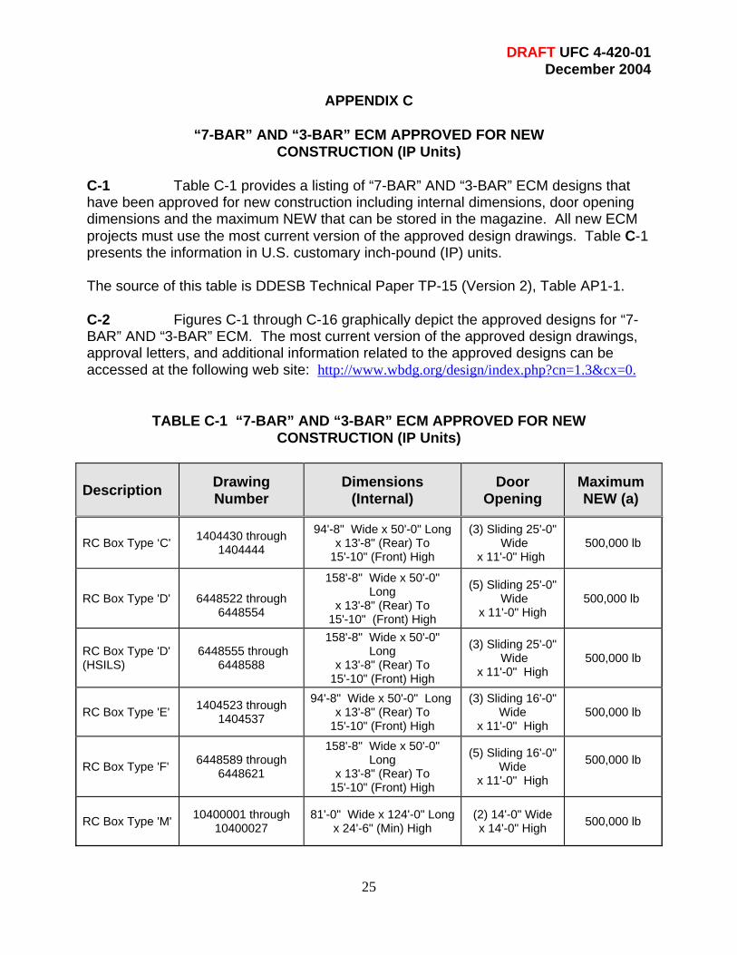
C-1 Table C-1 provides a listing of “7-BAR” AND “3-BAR” ECM designs that have been approved for new construction including internal dimensions, door opening dimensions and the maximum NEW that can be stored in the magazine. All new ECM projects must use the most current version of the approved design drawings. Table C-1 presents the information in U.S. customary inch-pound (IP) units. The source of this table is DDESB Technical Paper TP-15 (Version 2), Table AP1-1. C-2 Figures C-1 through C-16 graphically depict the approved designs for “7-BAR” AND “3-BAR” ECM. The most current version of the approved design drawings, approval letters, and additional information related to the approved designs can be accessed at the following web site: http://www.wbdg.org/design/index.php?cn=1.3&cx=0.
TABLE C-1 “7-BAR” AND “3-BAR” ECM APPROVED FOR NEW CONSTRUCTION (IP Units)
Description Drawing Number
Dimensions (Internal)
Door Opening
Maximum NEW (a)
RC Box Type ‘C' 1404430 through 1404444
94'-8" Wide x 50'-0" Long x 13'-8" (Rear) To
15'-10" (Front) High
(3) Sliding 25'-0" Wide
x 11'-0" High 500,000 lb
RC Box Type 'D'
6448522 through 6448554
158'-8" Wide x 50'-0" Long
x 13'-8" (Rear) To 15'-10" (Front) High
(5) Sliding 25'-0" Wide
x 11'-0" High 500,000 lb
RC Box Type 'D' (HSILS)
6448555 through 6448588
158'-8" Wide x 50'-0" Long
x 13'-8" (Rear) To 15'-10" (Front) High
(3) Sliding 25'-0" Wide
x 11'-0" High 500,000 lb
RC Box Type 'E' 1404523 through 1404537
94'-8" Wide x 50'-0" Long x 13'-8" (Rear) To
15'-10" (Front) High
(3) Sliding 16'-0" Wide
x 11'-0" High 500,000 lb
RC Box Type 'F' 6448589 through 6448621
158'-8" Wide x 50'-0" Long
x 13'-8" (Rear) To 15'-10" (Front) High
(5) Sliding 16'-0" Wide
x 11'-0" High
500,000 lb
RC Box Type 'M' 10400001 through 10400027
81'-0" Wide x 124'-0" Longx 24'-6" (Min) High
(2) 14'-0" Wide x 14'-0" High 500,000 lb

DRAFT UFC 4-420-01 December 2004
26
Description Drawing Number
Dimensions (Internal)
Door Opening
Maximum NEW (a)
RC Box 421-80-06 (Modified)
25'-0" Wide x 20'-0" Min. to
80'-0" Max. Length x 11'-0" High
Hinged 24'-0" Wide
x 10'-4" High 500,000 lb
RC Box Munitionslagerhause (MLH)90B 165,000 lb
RC Box Munitionslagerhause (MLH)180B
25'-1" Wide x 77'-9" Long x 13'-11" High
(1) 13'-1 1/2" Wide
x 9'-10" High 165,000 lb
RC Box Modular Storage Magazine (MSM)
25'-0" Wide x 20'-0" Min. to
80'-0" Max. Length x 14'-8" High
Hinged 24'-0" Wide
x 13'-11" High 500,000 lb
RC Box (Multi-cell)
High Performance Magazine
(HPM) - Concept Design -
Drawings not complete
Four cells each 21'-0" Wide
x 83'-0" Long x 16'-0" High
Horizontal Rolling Covers
Max Opening
21’-0” x 37’-11”
Varies depending
on configuration
240,000 lb Max
RC Circular Arch 1404310 through 1404324
25'-0" Wide x x 80'-0" Max. Length x
11'-11" (Rear) High
(1) Sliding 10'-0" Wide
x 10'-0" High or 16'-0" Wide x 10'-0" High
500,000 lb
RC Arch 421-80-05
26’-7 ¼” Wide x 90'-0" Max.
Length (normally length is 60' or
80') x 14'-0" (Rear) High
(1) Sliding 8'-0” Wide
x 8'-0” High or 10'-0” Wide x 10'-0” High
500,000 lb
RC FRELOC Stradley
33-15-74
25'-0" Wide x 90'-0" Max. Length (normally length is
60' or 80') x 14'-0" (Rear) High
(1) Sliding 8'-0" Wide
x 8'-0" High or 10'-0” Wide x 10'-0" High
500,000 lb
RC FRELOC Stradley
(Korean Version) 33-15-74
25'-0" Wide x 90'-0" Max. Length (normally length is
60' or 80') x 14'-0" (Rear) High
(1) Sliding 10'-0" Wide
x 10'-0" High 500,000 lb
Steel Oval Arch Munitionslagerhause (MLH)90S
165,000 lb

DRAFT UFC 4-420-01 December 2004
27
Description Drawing Number
Dimensions (Internal)
Door Opening
Maximum NEW (a)
Steel Oval Arch Munitionslagerhause (MLH)180S
165,000 lb
Steel Oval Arch 421-80-03
28'-2" Max Wide x 21'-0" Min. to 89'-0"
Max. Length x 14'-11" (Max) High
(1) Sliding 8'-0" Wide
x 8'-0" High or 10'-0" Wide x 10'-0" High
500,000 lb
Steel, Semi-Circular Arch 421-80-01
Approx. 26'-0" Wide x 19'-0" Min.
expandable up to most commonly used 89'-0"
Length x 14'-0" (Max) High
(1) Sliding 8'-0" Wide
x 8'-0" High or 10'-0" Wide x
10'-0 High
500,000 lb
Composite Circular Arch
1404375 through 1404389
25'-0" Wide x x 80'-0" Max. Length 13'-2" (Rear) High
(1) Sliding 10'-0" Wide
x 10'-0 High or 16'-0” Wide x 10'-0" High
500,000 lb
Composite Oval Arch
1404390 through 1404398
28'-2" Max Wide x 20'-0" Min. to 80'-0"
Max. Length x 15'-2" (Max) High
(1) Sliding 10'-
0" Wide x 10'-0" High
500,000 lb
Notes to Table C-1, “7-BAR’ AND “3-BAR” ECM APPROVED FOR NEW CONSTRUCTION (IP Units) Note (a) – Refer to paragraph 2.2.2 for siting considerations of ECM as exposed sites with approved maximum NEW less than 500,000 lb.

DRAFT UFC 4-420-01 December 2004
28
Figure C-1. RC Box, Type ‘C’ (IP Units)
EC
M
Des
igna
tion
Des
igne
r &
D
raw
ing
Num
ber
Max
imum
A
llow
able
N
et E
xplo
sive
W
eigh
t (N
EW
)
Dim
ensi
ons
(Int
erna
l)
D
oor
Ope
ning
DD
ESB
A
ppro
val
Dat
e
7-BAR
NAVFAC 1404430- 1404444
500,000 lb
94’-8” Wide x
50’-0” Long x 13’-8” (Rear) To 15’-10” (Front)
High
(3) Sliding
25’-0” Wide x 11’-0” High
5 NOV 1985
Comments/Design Considerations: May be built with or without a loading platform Single piece sliding doors High security hasp door lock

DRAFT UFC 4-420-01 December 2004
29
Figure C-2. RC Box, Type ‘D’ and RC Box, Type ‘D’ (HSILS) (IP Units)
EC
M
Des
igna
tion
Des
igne
r &
D
raw
ing
Num
ber
Max
imum
A
llow
able
N
et E
xplo
sive
W
eigh
t (N
EW
)
Dim
ensi
ons
(Int
erna
l)
D
oor
Ope
ning
DD
ESB
A
ppro
val
Dat
e
7-BAR
NAVFAC 6448522-6448554
500,000 lb
158’-8” Wide x 50’-0”
long x 13’-8” (Rear) To 15’-10” (Front)
High
(5) Sliding
25’-0” Wide x 11’-0” High
5 NOV 1985
Comments/Design Considerations: Superceded NAVFAC 1404465 through 1404478. May be built with or without a loading platform Single piece sliding doors High security hasp door lock Type D HSILS incorporates a High Security Integrated Locking System (HSILS)

DRAFT UFC 4-420-01 December 2004
30
Figure C-3. RC Box Type ‘E’ (IP Units)
EC
M
Des
igna
tion
Des
igne
r &
D
raw
ing
Num
ber
Max
imum
A
llow
able
N
et E
xplo
sive
W
eigh
t (N
EW
)
Dim
ensi
ons
(Int
erna
l)
D
oor
Ope
ning
DD
ESB
A
ppro
val
Dat
e
7-BAR
NAVFAC 1404523-1404537
500,000 lb
94’-8” Wide x
50’-0” Long x 13’-8” (Rear) To 15’-10”
(Front) High
(3) Sliding
16’-0” Wide x 11’-0” High
17 JUL 1987
Comments/Design Considerations: May be built with or without a loading platform Single piece sliding doors
o High security hasp door lock

DRAFT UFC 4-420-01 December 2004
31
Figure C-4. RC Box Type ‘F’ (IP Units)
EC
M
Des
igna
tion
Des
igne
r &
D
raw
ing
Num
ber
Max
imum
A
llow
able
N
et E
xplo
sive
W
eigh
t (N
EW
)
Dim
ensi
ons
(Int
erna
l)
D
oor
Ope
ning
DD
ESB
A
ppro
val
Dat
e
7-BAR
NAVFAC 6448589-6448621
500,000 lb
158’-8” Wide x 50’-0”
Long x 13’-8” (Rear) To 15’-10” (Front) High
(5) Sliding
16’-0” Wide x 11’-0” High
17 JUL 1987
Comments/Design Considerations: Superceded NAVFAC 1404541 through 1404555. May be built with or without a loading platform Single piece sliding doors High security hasp door lock

DRAFT UFC 4-420-01 December 2004
32
Figure C-5. RC Box Type ‘M’ (IP Units)
EC
M
Des
igna
tion
Des
igne
r &
D
raw
ing
Num
ber
Max
imum
A
llow
able
N
et E
xplo
sive
W
eigh
t (N
EW
)
Dim
ensi
ons
(Int
erna
l)
D
oor
Ope
ning
DD
ESB
A
ppro
val
Dat
e
7-
BAR
NAVFAC 10400001-10400027
500,000 lb
81’-0” Wide x 124’-0” Long
x 24’-6” (Min) High
(2) Sliding
14’-0” Wide x 14’-0” High
1 DEC 1999
Comments/Design Considerations: Provides for internal magazine access by
rail and truck. Designed for automated
ordnance stowage and retrieval by bridge crane and lifting devices. Alternately forklift may be used. May be built with or without a loading
platform Single piece sliding doors High security hasp door lock

DRAFT UFC 4-420-01 December 2004
33
Figure C-6. RC Box (421-80-06) Modified (IP Units)
EC
M
Des
igna
tion
Des
igne
r &
D
raw
ing
Num
ber
Max
imum
A
llow
able
N
et E
xplo
sive
W
eigh
t (N
EW
)
Dim
ensi
ons
(Int
erna
l)
D
oor
Ope
ning
DD
ESB
A
ppro
val
Dat
e
7-BAR
COE 421-80-06 (Modified)
500,000 lb
25’-0” Wide x 20’-0”
Min To 80’0” Max. Long x 11’-0” High
Hinged
24’-0” Wide x 10’-4” High
17 APR 2002
Comments/ Design Considerations: This design reflects a modified version
of the original design 421-80-06 dated 1 Oct 99. The original design was downgraded to undefined. For the magazine to be sited as a 7-Bar approved ECM the design must be modified with the revised drawings, S-9 through S-13. See the DDESB memo of 17 April 2002 for specific requirements for both new construction and for a retrofit to upgrade an existing magazine built to the original design." Double hinged doors

DRAFT UFC 4-420-01 December 2004
34
Figure C-7. RC Box (MLH) 180B (IP Units)
EC
M
Des
igna
tion
Des
igne
r &
D
raw
ing
Num
ber
Max
imum
A
llow
able
N
et E
xplo
sive
W
eigh
t (N
EW
)
Dim
ensi
ons
(Int
erna
l)
D
oor
Ope
ning
DD
ESB
A
ppro
val
Dat
e
7-
BAR
German Munition-slagerhause (MLH) 180B
165,000lb
25’-1” Wide x 77’-9” Long x 13’-11” High
(1) 13’-1 1/2”
Wide x 9’-10” High
12-DEC-77 18-AUG-87
Comments/Design Considerations: NATO explosives safety standards
limit this magazine to an HD 1.1 of 165,000 pounds NEW. For siting at U.S installations, where encumbered land is completely within U.S. owned or controlled property, magazine can be sited as an Undefined ECM with an Explosives limit of 250,000 pounds NEW. Considered as a 7-Bar ECM for sitings involving 165,000 pounds NEW or less. Single piece sliding door

DRAFT UFC 4-420-01 December 2004
35
Figure C-8. RC Box (MSM) (IP Units)
EC
M
Des
igna
tion
Des
igne
r &
D
raw
ing
Num
ber
Max
imum
A
llow
able
N
et E
xplo
sive
W
eigh
t (N
EW
)
Dim
ensi
ons
(Int
erna
l)
D
oor
Ope
ning
DD
ESB
A
ppro
val
Dat
e
7-BAR
Modular Storage Magazine (MSM)
500,000 lb
25’-0” Wide x 20’-
0”Min. to 80’0” Long x 14’-8” High
Hinged 24’-0” Wide x 13’-11”
High
11 Jul 2002
Comments/ Design Considerations: This 14’-8” ceiling height Modular
Storage Magazine (MSM) design was developed for construction of magazines 2580 and 2581 at Hill AFB, Ogden, Utah, and is basically a larger version of the MSM (11 foot ceiling height) shown on drawings 421-80-06. Double hinged doors

DRAFT UFC 4-420-01 December 2004
36
Figure C-9. RC Box (Multi-Cell) (IP Units)
EC
M
Des
igna
tion
Des
igne
r &
D
raw
ing
Num
ber
Max
imum
A
llow
able
N
et E
xplo
sive
W
eigh
t (N
EW
) D
imen
sion
s (I
nter
nal)
Doo
r O
peni
ng
DD
ESB
A
ppro
val
Dat
e
7-
BAR
RC Box (multi-cell), HPM – Concept Design
Varies Depending On Configuration 240,000 lb Maximum
Four Cells Each
21’-0” Wide x 83’-0” Long x 16’-0” High
Ordnance
Bay: Maximum 21’-0” x 37’-11”
27 Jan 2000
Comments/Design Considerations: The HPM design concept was approved by
DDESB 27 Jan 2000. A preliminary concept design was completed 3 July 2001. The HPM consist of four separate ordinance storage bays that are treated as independent magazines (i.e., independent MCE). Each storage bay can store up to 30,000 lbs. or can be subdivided into two storage areas with the use of the Modular Wall. Each subdivided area can store up to 30,000 lbs NEW. The separation of the storage bays allows for storage of incompatible ordinance in adjacent bays. The maximum storage capacity of a HPM with no subdivided bays is 120,000 lbs. NEW or 240,000 lbs NEW if all bays are subdivided. Due to the separation of ordnance in non-proprogation cells the HPM is sited based on 60,000 pounds NEW.. The HPM is not earth-covered but is earth-bermed (except for the truck entrance) with moveable RC covers over the storage cells. The area above the storage cells is enclosed by a lightweight metal building. A bridge crane with lifting devices is used for stowage and retrieval of AE. No HPM has been built to date and the final
Design drawings must be finalized and approved by the DDESB prior to construction.

DRAFT UFC 4-420-01 December 2004
37
Figure C-10. RC Circular Arch (IP Units) C
EC
M
Des
igna
tion
Des
igne
r &
D
raw
ing
Num
ber
Max
imum
A
llow
able
N
et E
xplo
sive
W
eigh
t (N
EW
)
Dim
ensi
ons
(Int
erna
l)
D
oor
Ope
ning
DD
ESB
A
ppro
val
Dat
e
7-BAR
NAVFAC 1404310-1404324
500,000 lb
25’-0” Wide x 80’-0” Max. Long x 11’-11’
(Rear) High
(1) Sliding 10’-0” Wide x 10’-
0”High or 16’-0” Wide x 10’-0”
High
15 JUL 1983
Comments/ Design Considerations: Superceded NAVFAC's original (1954)
Standard Drawings 627954 thru 627957, 649602 thru 649605, 658384 thru 658388, 724368, 751861, 764596 thru 764597, 793746 thru 793748, 803060, and 822978 thru 822989. May be built with or without a loading
platform Single piece sliding door High security hasp door lock

DRAFT UFC 4-420-01 December 2004
38
Figure C-11. RC Arch (421-80-05) (IP Units)
EC
M
Des
igna
tion
Des
igne
r &
D
raw
ing
Num
ber
Max
imum
A
llow
able
N
et E
xplo
sive
W
eigh
t (N
EW
)
Dim
ensi
ons
(Int
erna
l)
D
oor
Ope
ning
DD
ESB
A
ppro
val
Dat
e
7-
BAR
COE 421-80-05
500,000 lb
26’-7 ¼” Wide x 90’-0”
Max. Long (normal length is 60’ or 80’) x 14’-0” (Rear) High
(1) Sliding 8’-0”
Wide x 8’-0” High OR 10’-0” Wide x 10’-0”
High
8 SEPT1998
Comments/ Design Considerations: Constructed using the Techspan Precast
Concrete System, developed by the Reinforced Earth Company, for arch construction. The headwall and door are derived from 33-15-74. Single piece sliding door High security hasp door lock
DRAFT UFC 4-420-01 December 2004
39
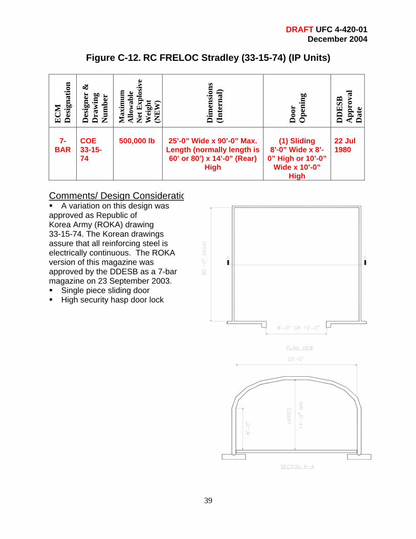
Figure C-12. RC FRELOC Stradley (33-15-74) (IP Units)
EC
M
Des
igna
tion
Des
igne
r &
D
raw
ing
Num
ber
Max
imum
A
llow
able
N
et E
xplo
sive
W
eigh
t (N
EW
)
Dim
ensi
ons
(Int
erna
l)
D
oor
Ope
ning
DD
ESB
A
ppro
val
Dat
e
7-
BAR
COE 33-15-74
500,000 lb
25’-0” Wide x 90’-0” Max.
Length (normally length is 60’ or 80’) x 14’-0” (Rear)
High
(1) Sliding
8’-0” Wide x 8’-0” High or 10’-0”
Wide x 10’-0” High
22 Jul 1980
Comments/ Design Considerations: A variation on this design was
approved as Republic of Korea Army (ROKA) drawing 33-15-74. The Korean drawings assure that all reinforcing steel is electrically continuous. The ROKA version of this magazine was approved by the DDESB as a 7-bar magazine on 23 September 2003. Single piece sliding door High security hasp door lock

DRAFT UFC 4-420-01 December 2004
40
Figure C-13. Steel Oval Arch (421-80-03) (IP Units)
EC
M
Des
igna
tion
Des
igne
r &
D
raw
ing
Num
ber
Max
imum
A
llow
able
N
et E
xplo
sive
W
eigh
t
Dim
ensi
ons
(Int
erna
l)
D
oor
Ope
ning
DD
ESB
A
ppro
val
Dat
e
7-
BAR
COE 421-80-03
500,000 lb
28’-2” Max Wide x 21’-0”
Min. to 89’-0” Max. Length x 14’-11” (Max) High
(1) Sliding
8’-0” Wide x 8’-0” High or 10’-0” Wide x 10’-0”
28 DEC 1992
Comments/Design Considerations: Replaced 33-15-73. Arch design
composed of a 1 gage (0.280 inch) corrugated steel arch. Single piece sliding door High security hasp door lock

DRAFT UFC 4-420-01 December 2004
41
Figure C-14. Steel Semi-Circular Arch (421-80-01) (IP Units)
EC
M
Des
igna
tion
Des
igne
r &
D
raw
ing
Num
ber
Max
imum
A
llow
able
N
et E
xplo
sive
W
eigh
t
Dim
ensi
ons
(Int
erna
l)
D
oor
Ope
ning
DD
ESB
A
ppro
val
Dat
e
7-
BAR
COE 421-80-01
500,000 lb
Approx. 26’-0” Wide x 19’-0” Min. expandable up to most commonly used 89’-0” Length x
14’-0” (Max) High
(1) Sliding
8’-0” Wide x 8’-0” High or 10’-0” Wide
x 10’-0” High
28 JUN 1988
Comments/Design Considerations: Replaces 33-15-73. Drawing permits the
use of 2" deep or 5.5" deep corrugated steel arch. Single piece sliding door High security hasp door lock

DRAFT UFC 4-420-01 December 2004
42
Figure C-15. Composite Circular Arch (IP Units)
EC
M
Des
igna
tion
Des
igne
r &
D
raw
ing
Num
ber
Max
imum
A
llow
able
N
et E
xplo
sive
W
eigh
t (N
EW
)
Dim
ensi
ons
(Int
erna
l)
D
oor
Ope
ning
DD
ESB
A
ppro
val
Dat
e
7-BAR
NAVFAC 1404375-1404389
500,000 lb
25’-0” Wide x 80’-0” Max. Length x 13’-2”
(Rear) High
(1) Sliding
10’-0” Wide x 10’-0” High or 16’-0”
Wide x 10’-0” High
14 JAN 1986
Comments/Design Considerations: Composite circular arch design composed
of an internal 10 gage (0.138 inch) corrugated steel arch with reinforced concrete overlay. May be built with or without a loading
platform Single piece sliding door High security hasp door lock
DRAFT UFC 4-420-01 December 2004
43
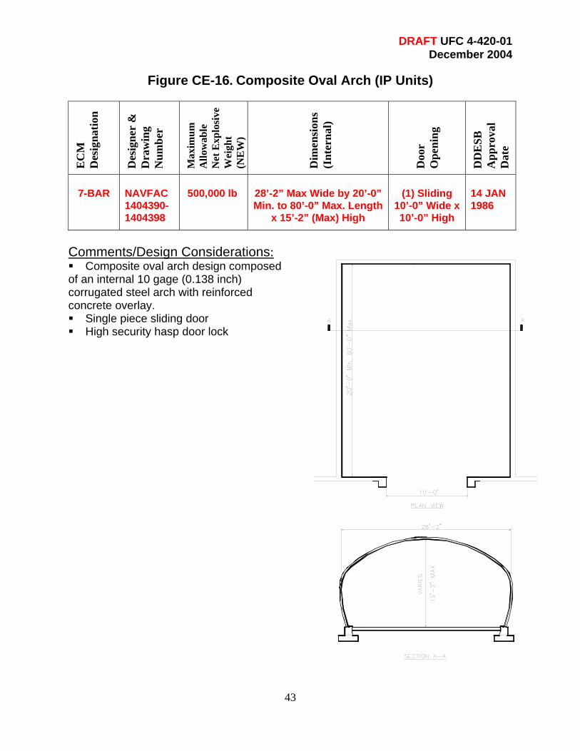
Figure CE-16. Composite Oval Arch (IP Units)
EC
M
Des
igna
tion
Des
igne
r &
D
raw
ing
Num
ber
Max
imum
A
llow
able
N
et E
xplo
sive
W
eigh
t (N
EW
)
Dim
ensi
ons
(Int
erna
l)
D
oor
Ope
ning
DD
ESB
A
ppro
val
Dat
e
7-BAR
NAVFAC 1404390-1404398
500,000 lb
28’-2” Max Wide by 20’-0” Min. to 80’-0” Max. Length
x 15’-2” (Max) High
(1) Sliding
10’-0” Wide x 10’-0” High
14 JAN 1986
Comments/Design Considerations: Composite oval arch design composed
of an internal 10 gage (0.138 inch) corrugated steel arch with reinforced concrete overlay. Single piece sliding door High security hasp door lock

DRAFT UFC 4-420-01 December 2004