unfolding & foldingunfolding & folding … chapter 8 dr. shoab a. khan folding architecture...
TRANSCRIPT

Unfolding & FoldingUnfolding & Folding TransformationsTransformations
Chapter 8
Dr. Shoab A. Khan

Folding Architecture
Folding design are time-multiplexed architecturesMathematical Transformations are also used to foldMathematical Transformations are also used to fold a DFG These transformations take DFG and systematically y ygenerate a folded architecture The techniques also generate a schedule
Clockwise mapping of multiple operations of the DFG on fewer HW computational units of the folded architecturefolded architecture
2Digital Design of Signal Processing Systems, John Wiley & Sons by Dr. Shoab A. Khan

Folding Design Decision
The design decision is made based on the ratio of sampling fs and circuit clock fcp g s c
fs is specific to an application fs is constraint by Nyquist sampling criteria or bandpass sampling techniques
fc depends upon several factors Target technologyTarget technologyDigital design options (Adders, Multipliers)Power considerations etcPower considerations etc
3Digital Design of Signal Processing Systems, John Wiley & Sons by Dr. Shoab A. Khan

Nyquist Theorem and Bandpass Sampling
For perfect reconstruction, minimum sampling rate has to be greater than or equal to twice the maximum frequency content in the signalFor bandpass signals, bandpass sampling can be performedperformed
Ns ff 2≥
Where the sampling rate is set to lower valuesThe spectrum is intentionally aliased to fall on unoccupied lower digital frequenciesdigital frequencies
4Digital Design of Signal Processing Systems, John Wiley & Sons by Dr. Shoab A. Khan

Software Defined Radio Architecture and Band-pass Sampling
Typical Software Defined Radio Architecture
5Digital Design of Signal Processing Systems, John Wiley & Sons by Dr. Shoab A. Khan

Software Defined Radio Architecture and Band-pass Sampling
(a)
(b)
6Digital Design of Signal Processing Systems, John Wiley & Sons by Dr. Shoab A. Khan
Digital Communication Receiver (a). Direct conversion receiver (b). IF conversion receiver

Software Defined Radio Architecture and Band-pass Sampling
The signal is voice video image or data that isThe signal is voice, video, image or data that is modulated and mixed with a carrier to take allotedlimited bandwidth in air
is the highest frequency content of the baseband i l
B = 2fNfN
signal.The signal can be sampled at lower rate using band-pass sampling techniquepass sampling technique
7Digital Design of Signal Processing Systems, John Wiley & Sons by Dr. Shoab A. Khan
Baseband signal mixed with a carrier for signal translation in frequency band

Band-pass Sampling
(a)(a)
(b)
(a) The spectrum of a 20 MHz signal centered at IF of 80 MHz (b) The spectrum of band pass sampled signal f = 65 MHz
8Digital Design of Signal Processing Systems, John Wiley & Sons by Dr. Shoab A. Khan
(b) The spectrum of band-pass sampled signal, fs = 65 MHz
ADC Bandwidth and Band-pass Sampling
ADC bandwidth (BW) is also an important consideration This bandwidth corresponds to the highest frequency at which the internal electronics of ADC can pass the signal without any attenuation
9Digital Design of Signal Processing Systems, John Wiley & Sons by Dr. Shoab A. Khan

Unfolding Techniques
SW: unfolding transformation is unrolling a loop tounfolding transformation is unrolling a loop to execute several iterations in one unrolled-iteration
HW: unfolding corresponds to mathematical
f Gtransformation on a DFG to replicate its functionality for computing multiple output samples for multiple input samplessamples for multiple input samples
10Digital Design of Signal Processing Systems, John Wiley & Sons by Dr. Shoab A. Khan

SW: Loop Unrolling
Example: dot product of two arrays of size N
sum=0;for (i=0; i<N; i++)
sum += a[i]*b[i];
11Digital Design of Signal Processing Systems, John Wiley & Sons by Dr. Shoab A. Khan

SW: Loop Unrolling
sum1=0;sum2=0;;sum3=0;sum4=0;
for(i=0; i<N/L; i++)for(i=0; i<N/L; i++){
sum1 += a[i]*b[i];sum2 += a[i+1]*b[i+1];
3 + [i+2]*b[i+2]sum3 += a[i+2]*b[i+2];sum4 += a[i+3]*b[i+3];
}}
sum = sum0+sum1+sum2+sum3;
12Digital Design of Signal Processing Systems, John Wiley & Sons by Dr. Shoab A. Khan

HW: Unfolding Transformation
Unfolding by a factor JS0: Each node U of the original DFG is replicated JS0: Each node U of the original DFG is replicated Jtimes as U0,…,UJ-1
S1: For two connected nodes U and V in the original DFG with w number of delays, draw J edges such that each edge j for j=0,1,…,J-1 connects node U to node V(j+w)%J with delays⎥⎢ + wjnode Uj to node V(j+w)%J with delays
% and are remainder and floor operator⎥⎦⎥
⎢⎣⎢ +
Jwj
⎣ ⎦
13Digital Design of Signal Processing Systems, John Wiley & Sons by Dr. Shoab A. Khan

0 0 01=0 1
1 12=11 2
22 20=2 00
14Digital Design of Signal Processing Systems, John Wiley & Sons by Dr. Shoab A. Khan

A CB
A0 B0 C0
A1 B1 C1
A2 B2 C2
15Digital Design of Signal Processing Systems, John Wiley & Sons by Dr. Shoab A. Khan

Example 8-2
(a)
Figure 8-5 (a) A 2nd order TDF structure
(a)(b)
16Digital Design of Signal Processing Systems, John Wiley & Sons by Dr. Shoab A. Khan
Figure 8-5 (a) A 2 order TDF structure (b) Folding of 2nd order TDF structure by folding factor of 2

Loop Unrolling for SW to HW Mappingshort xbuf[N+L-1];short xbuf[N L 1];short hfb[L];short ybf[N];
short *xptr, *hptr;int sum;int m,n;
& fxptr = &xbf[L-1];hptr = hbf;for (n=0; n<N; n++){
sum = 0;for(k=0, m=n; k<L; k++, m--)
sum += xptr[m]*hptr[k];ybf[n] = sum;ybf[n] = sum;
}
The unrolled loop for effective HW mapping is given here.
xptr = &xbf[L-1];hptr = hbf;for (n=4-1; n<N; n+=4)for (n 4 1; n<N; n+ 4){
sum_n = 0;sum_n_1 = 0;sum_n_2 = 0;sum_n_3 = 0;
for (k=0, m=n; k<L; k++, m--)( ){
sum_n += hptr[k] * xptr[m];sum_n_1 += hptr[k] * xptr[m-1];sum_n_2 += hptr[k] * xptr[m-2];sum_n_3 += hptr[k] * xptr[m-3];
}ybf[n] = sum_n;bf[n 1] s m np1
17Digital Design of Signal Processing Systems, John Wiley & Sons by Dr. Shoab A. Khan
ybf[n-1] = sum_np1;ybf[n-2] = sum_np2;ybf[n-3] = sum_np3;
}
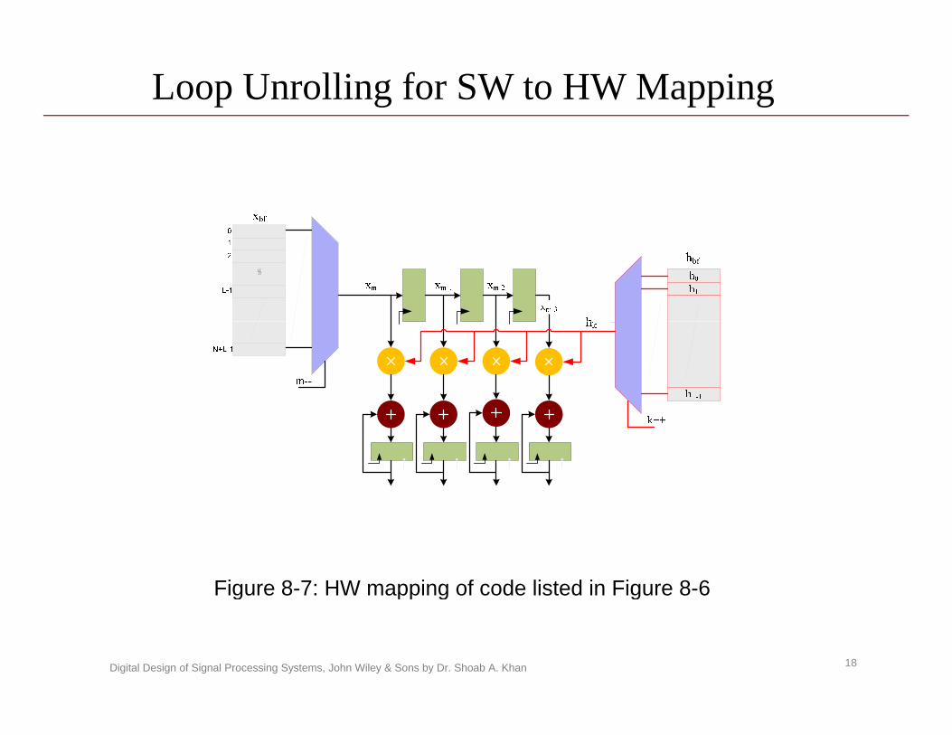
Loop Unrolling for SW to HW Mapping
Figure 8-7: HW mapping of code listed in Figure 8-6
18Digital Design of Signal Processing Systems, John Wiley & Sons by Dr. Shoab A. Khan
g pp g g

Unfolding to Maximize use of Compression Tree
(a)( )
(b)
Figure 8-8: Unrolling an FIR filter (a) A 4-Coefficient FIR Filter
19Digital Design of Signal Processing Systems, John Wiley & Sons by Dr. Shoab A. Khan
g g ( )(b) The filter is unrolled by a factor of 2

Unfolding for Effective Use of FPGA Resources
Figure 8-9: Pipelined FIR filter for effective mapping on FPGAs with DSP48 blocks.
20Digital Design of Signal Processing Systems, John Wiley & Sons by Dr. Shoab A. Khan
g p pp g

Parallel Processing with Embedded Blocks in FIR
( )(a)
(b)
Figure 8-10: Unfolding for mapping on embedded pipeline MAC unit (a) The DFG is appropriately pipeline (b) The pipeline DFG is unfolded for effective mapping on embedded MAC units
21Digital Design of Signal Processing Systems, John Wiley & Sons by Dr. Shoab A. Khan
(b) The pipeline DFG is unfolded for effective mapping on embedded MAC units

Unfolding and Retiming in Feedback Designs
(a) (b)
Figure 8-11: Unfolding and Retiming of Feedback DFG (a) A recursive DFG with 6 algorithmic registers (b) Retiming of resisters for associating algorithmic registers with computational nodes for effective mapping
(c)
22Digital Design of Signal Processing Systems, John Wiley & Sons by Dr. Shoab A. Khan
(b) Retiming of resisters for associating algorithmic registers with computational nodes for effective mapping (c) An unfolded design for effective utilization of algorithmic registers

Unfolding and Area-Power-throughput tradeoff
IPB increasesDesign process more number of samplesDesign process more number of samplesThroughput same with a slower circuit clock.
The circuit clock gets slower as the critical pathThe circuit clock gets slower as the critical path is increased
Effective use of extra registers in feedback designIncreasing the performance of feed-forward designs with embedded units
Parallel processing with DSP48
23Digital Design of Signal Processing Systems, John Wiley & Sons by Dr. Shoab A. Khan
Folding Techniques
Time-shared architectures are designed once the circuit clock is at least twice greater than the gsampling clock
fc > 2 fsThe design can reuse its hardware resources
Input data valid for multiple of fc
24Digital Design of Signal Processing Systems, John Wiley & Sons by Dr. Shoab A. Khan

Basic Definition
Folding is a mathematical technique of finding a time-multiplexed architecture and a schedule of pmapping multiple operations of a DFG on fewer hardware computational units. Folding Factor is defined as maximum number of operations in a DFG mapped on a shared computational unitcomputational unit. Folding Set or Folding Scheduler is the sequence of operations of a DFG mapped on a single p pp gcomputational unit.
25Digital Design of Signal Processing Systems, John Wiley & Sons by Dr. Shoab A. Khan

Example 8-3
A DFG implementingA DFG implementing out=(x1+x2+a1x3)a2
A
a2x1x2
t3
N
t1
yN
NN
A1
A2
N
a1
x3
N
t2
N
NN
M1 M2
Folded architecture for the DFG
26Digital Design of Signal Processing Systems, John Wiley & Sons by Dr. Shoab A. Khan
Folded architecture for the DFG

Folding Regular Structure DFGs
The algorithms that exhibit regular structures can be easily folded. y
Implementation of an FIR filter is a good example
For any regular structure algorithm the folding factor is simply computed as
⎥⎦
⎥⎢⎣
⎢= c
ffN⎦⎣ sf
27Digital Design of Signal Processing Systems, John Wiley & Sons by Dr. Shoab A. Khan

Example 8-4(a) (b)(a) (b)
Figure 8-13: A Folded by 3 architecture for a 9 coefficients FIR filter (a) Folded DF architecture
28Digital Design of Signal Processing Systems, John Wiley & Sons by Dr. Shoab A. Khan
(a) Folded DF architecture (b) (b) Folded TDF architecture

Example 8-5
(a) (b)
Figure 8-14: Flow graphs realizing 8-point FFT algorithms using (a) Radix-2 butterflies
29Digital Design of Signal Processing Systems, John Wiley & Sons by Dr. Shoab A. Khan
(a) Radix-2 butterflies (b) Radix-4 butterflies

Memory Based Folded FFT Processor
Figure 8-15: Two dual port memories based
30Digital Design of Signal Processing Systems, John Wiley & Sons by Dr. Shoab A. Khan
Figure 8 15: Two dual port memories based FFT processor with one radix-2 butterfly in the datapath
Systolic Folded Architecture
All the butterflies in one stage of the FFT are folded and mapped on a single butterfly Processing pp g y gElement (PE) To ensure systolic operation, intermediate registers and multiplexers are placed such that the design keep processing data for computation of FFT and right inputs are always available to every PE inright inputs are always available to every PE in every clock cycle for full utilization of the HW.
31Digital Design of Signal Processing Systems, John Wiley & Sons by Dr. Shoab A. Khan

Example 8-7
The design for the systolic 8-point FFT implementation.
Figure 8-16: A systolic MDC architecture implementing an 8-point decimation in frequency FFT algorithm
32Digital Design of Signal Processing Systems, John Wiley & Sons by Dr. Shoab A. Khan

Mathematical Transformation for Folding
In many signal processing application the algorithm is transformed for easy folding. y gMany feed-forward algorithms can be transformed to use recursive formulation for serial computation of output samples.
33Digital Design of Signal Processing Systems, John Wiley & Sons by Dr. Shoab A. Khan

Mathematical Transformation
First compute the folding order and a folding set for a DFG, Computes the number of delays on each edge in the folded graph using folding transformation The folded architecture periodically executes operationsThe folded architecture periodically executes operations of the DFG according to the folding set
34Digital Design of Signal Processing Systems, John Wiley & Sons by Dr. Shoab A. Khan
Figure 8-18: An edge in a DFG connecting nodes i and j with w delays

Example: Folding Transformation
35Digital Design of Signal Processing Systems, John Wiley & Sons by Dr. Shoab A. Khan

Algorithmic Transformation
In many applications a more convenient HW mapping can be conceived by performing an pp g y p galgorithmic transformation of the design. For FFT computation Goetzl algorithm is a good example where the FFT computation is implemented as an IIR filter. This formulation is effective if only few coefficientsThis formulation is effective if only few coefficients of the frequency spectrum are to be computed.
36Digital Design of Signal Processing Systems, John Wiley & Sons by Dr. Shoab A. Khan

FFT as Circular Convolution
A more interesting transformation is derived in [] that converts an FFT computation to circular convolutionconverts an FFT computation to circular convolution summation.The transformation helps in developing an effective p p garchitecture for FFT computation.Circular convolution equationq
222
)(1
)][(][ nkN nk
WWWkX −−−
∑ )(
0
22 )][(][ nkN
nNN WWnxWkX
=∑=
37Digital Design of Signal Processing Systems, John Wiley & Sons by Dr. Shoab A. Khan

Mathematical Transformation
Compute the folding order N and a folding set for a DFGComputes the number of delays on each edge in theComputes the number of delays on each edge in the folded graph using folding transformation The folded architecture periodically executes operations p y pof the DFG according to the folding set in N circuit clock
ijwZ −
38Digital Design of Signal Processing Systems, John Wiley & Sons by Dr. Shoab A. Khan
An edge in a DFG connecting nodes i and j with wij delays

Folding Transformation
ijwZ −
ijFZ −
39Digital Design of Signal Processing Systems, John Wiley & Sons by Dr. Shoab A. Khan
Folding Transformation
ijFZ −
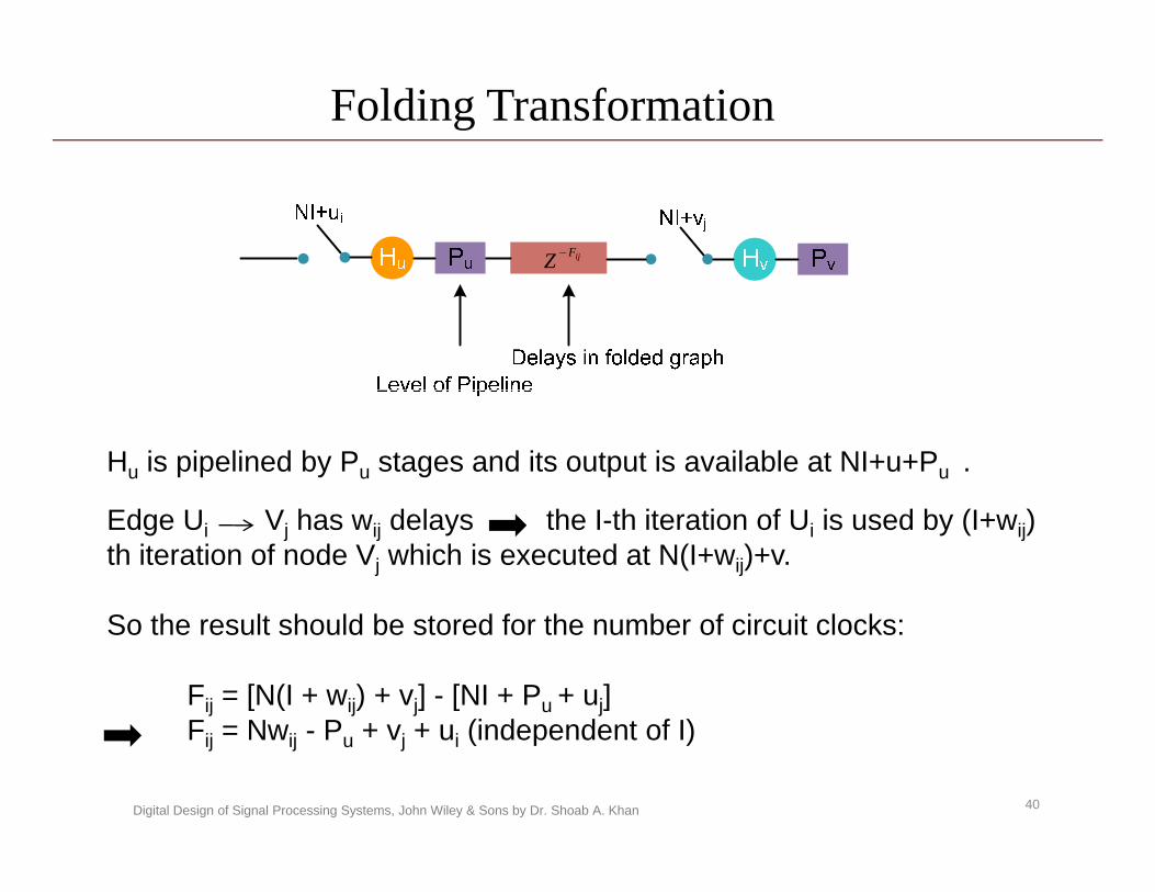
Hu is pipelined by Pu stages and its output is available at NI+u+Pu .
Edge Ui Vj has wij delays the I-th iteration of Ui is used by (I+wij) th iteration of node Vj which is executed at N(I+wij)+v.
S th lt h ld b t d f th b f i it l kSo the result should be stored for the number of circuit clocks:
Fij = [N(I + wij) + vj] - [NI + Pu + uj]F = Nw P + v + u (independent of I)
40Digital Design of Signal Processing Systems, John Wiley & Sons by Dr. Shoab A. Khan
Fij = Nwij - Pu + vj + ui (independent of I)

Folding or Order N=4
Pipeline stagesPA = 1
AdditionsA = {4,2,3,1}
MultiplicationM = {5,8,6,7}
41Digital Design of Signal Processing Systems, John Wiley & Sons by Dr. Shoab A. Khan
A PM = 2
{ } { }

Folding IIR Filter with N=4
receive send
PNF +
0 3– 0 1– 4(1) F1 3– 1 1– 4(1) F
15
12
=+==+=
iju ijij u - v P– Nw F +=
5 3– 1 1– 4(2) F3 3– 3 1– 4(1) F2 3– 2 1– 4(1) F
18
17
16
=+==+==+=
00224(0)F0 0– 1 1– 4(0) F0 2– 3 1– 4(0) F
( )
42
31
18
+=+==+=
Valid Folding with pipelining 0 Fij ≥
Valid Folding without pipelining 1F ≥1 3– 2 2– 4(1) F0 2– 0 2– 4(1) F0 0– 2 2– 4(0) F
73
64
53
=+==+==+=
42Digital Design of Signal Processing Systems, John Wiley & Sons by Dr. Shoab A. Khan
Valid Folding without pipelining 1Fij ≥1 1– 0 2– 4(1) F84 =+=

Folding of Biquad Filter N=4
Additions Multiplication
43Digital Design of Signal Processing Systems, John Wiley & Sons by Dr. Shoab A. Khan
A = {4,2,3,1} M = {5,8,6,7}

Example: Folding Transformation
u- v PWN F iju ijij ++×=
0 Pu = 0 Pv =1 2– 0 3 F4 2– 0 23 F
3 2– 2 3 F
24
13
12
=+==+×=
=+=
1 0– 1 0 F1 0 1 0 F1 2– 0 3 F
35
45
14
=+==−+==+=
}{ 14,5, Sa = }{ 23, Sm =
44Digital Design of Signal Processing Systems, John Wiley & Sons by Dr. Shoab A. Khan
1 1– 2 0 F51 =+=