undulator physics april 29, 2004 heinz-dieter nuhn, slac / ssrl facility advisory committee meeting...
Post on 19-Dec-2015
218 views
TRANSCRIPT

Undulator Physics April 29, 2004 Heinz-Dieter Nuhn, SLAC / SSRLFacility Advisory Committee Meeting [email protected]@slac.stanford.edu
Undulator PhysicsDiagnostics / Commissioning Strategy
Heinz-Dieter Nuhn, SLAC / SSRLApril 29, 2004
Undulator PhysicsDiagnostics / Commissioning Strategy
Heinz-Dieter Nuhn, SLAC / SSRLApril 29, 2004
Undulator Overview FEL Parameters Diagnostics and Commissioning Strategy
Undulator Overview FEL Parameters Diagnostics and Commissioning Strategy

Undulator Physics April 29, 2004 Heinz-Dieter Nuhn, SLAC / SSRLFacility Advisory Committee Meeting [email protected]@slac.stanford.edu
Linac Coherent Light Source
Near Hall
Far Hall
Undulator

Undulator Physics April 29, 2004 Heinz-Dieter Nuhn, SLAC / SSRLFacility Advisory Committee Meeting [email protected]@slac.stanford.edu

Undulator Physics April 29, 2004 Heinz-Dieter Nuhn, SLAC / SSRLFacility Advisory Committee Meeting [email protected]@slac.stanford.edu
Undulator Segment Prototype

Undulator Physics April 29, 2004 Heinz-Dieter Nuhn, SLAC / SSRLFacility Advisory Committee Meeting [email protected]@slac.stanford.edu
Undulator Type planar hybridMagnet Material NdFeBWiggle Plane horizontalGap 6.5 mmPeriod Length 3.0 ± 0.003 cmEffective On-Axis Field 1.296 TEffective Undulator Parameter K 3.630 ± 0.015 %Segment Phase Slippage Tolerance 10
degrees
Module Length 3.40 mNumber of Modules 33Undulator Magnet Length 112.2 m
Standard Break Lengths 49.6 - 49.6 - 72.3 cmTotal Device Length 130.4 m
Lattice Type FODOMagnet Type permanentNominal Magnet Length 5 cmQF Gradient 60 T/mQD Gradient -60 T/mAverage Function at 1.5 Å (14.08 GeV) 30 mAverage Function at 15. Å (4.45 GeV) 8.9 mLowest Usable Energy 1.84 GeV
Summary of Nominal Undulator ParametersSummary of Nominal Undulator Parameters

Undulator Physics April 29, 2004 Heinz-Dieter Nuhn, SLAC / SSRLFacility Advisory Committee Meeting [email protected]@slac.stanford.edu
Beam Based Alignment Tolerances (Paul Emma)Beam Based Alignment Tolerances (Paul Emma)

Undulator Physics April 29, 2004 Heinz-Dieter Nuhn, SLAC / SSRLFacility Advisory Committee Meeting [email protected]@slac.stanford.edu
FEL SimulationsFEL Simulations
Parameter Range
Wavelength
Charg
e
15 Å1.5 Å
0.2 nC
1.0 nCstrong wakefields
loss
es
due t
osp
on.
rad.
deep s
atu
rati
on
Operation Space
Energy 14.1 GeV 4.4 GeV
Current 3.4 kA 3.4 kA
Charge 0.2 - 1 nC 0.2 - 1 nC
Slice Emittance 1.2 mm mrad 1.2 mm mrad
Slice Energy Spread 0.01 % 0.025 %
Undulator Period 3 cm 3 cm
Undulator Parameter 3.63 3.63
-function 18 m 7.5 m
Wavelength 1.5 Å 15 ÅLowering the charge reduces bunch
length, current and emittance
ParmelaParmelaParmelaParmela ElegantElegantElegantElegant GenesisGenesisGenesisGenesis
space-chargespace-charge compression, wakes, CSR, …compression, wakes, CSR, … SASE FEL with wakesSASE FEL with wakes
Start-To-End Simulations:Start-To-End Simulations:
Undulator Physics April 29, 2004 Heinz-Dieter Nuhn, SLAC / SSRLFacility Advisory Committee Meeting [email protected]@slac.stanford.edu
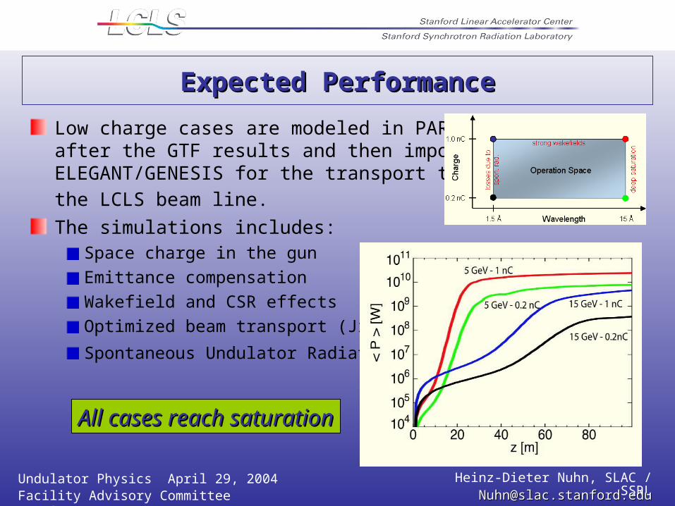
Expected PerformanceExpected Performance
Low charge cases are modeled in PARMELAafter the GTF results and then imported into ELEGANT/GENESIS for the transport through
the LCLS beam line. The simulations includes:
Space charge in the gun
Emittance compensation
Wakefield and CSR effects
Optimized beam transport (Jitter)
Spontaneous Undulator Radiation
All cases reach saturationAll cases reach saturation

Undulator Physics April 29, 2004 Heinz-Dieter Nuhn, SLAC / SSRLFacility Advisory Committee Meeting [email protected]@slac.stanford.edu
Risk Assessment: Undulator LengthRisk Assessment: Undulator Length
Saturation predicted 40 m before undulator end
Space for Undulator Extension Available if needed.
Saturation predicted 40 m before undulator end
Space for Undulator Extension Available if needed.
Length of Undulator Hall 175 m
Length of Undulator 130 m
Length of Undulator Hall 175 m
Length of Undulator 130 m
Available Undulator
Length
Available Undulator
Length
Extendable Undulator
Length
Extendable Undulator
Length
Nominal Working Point
Nominal Working Point
1.7 mm mrad
1.7 mm mrad
1.2 mm mrad
1.2 mm mrad

Undulator Physics April 29, 2004 Heinz-Dieter Nuhn, SLAC / SSRLFacility Advisory Committee Meeting [email protected]@slac.stanford.edu
Diagnostics and Commissioning WorkshopDiagnostics and Commissioning Workshop
LCLS Diagnostics and Commissioning Workshop
Dates
January 19-20, 2004
LocationUCLA, Los Angeles, USA
http://ssrl.slac.stanford.edu/lcls/undulator/meetings/2004-01-19_diagnostics_comissioning/Workshop Website
http://www-ssrl.slac.stanford.edu/lcls/technotes/lcls-tn-04-2.pdf
http://www.slac.stanford.edu/pubs/slacreports/slac-r-715.html
Workshop Report

Undulator Physics April 29, 2004 Heinz-Dieter Nuhn, SLAC / SSRLFacility Advisory Committee Meeting [email protected]@slac.stanford.edu
GoalsGoals
End-Of-Construction Goal
Defined by DOE to close-off construction project (CD-4)
One of the first Commissioning Milestones
Commissioning Goal
Get LCLS ready for operation
End-Of-Construction Goal
Defined by DOE to close-off construction project (CD-4)
One of the first Commissioning Milestones
Commissioning Goal
Get LCLS ready for operation

Undulator Physics April 29, 2004 Heinz-Dieter Nuhn, SLAC / SSRLFacility Advisory Committee Meeting [email protected]@slac.stanford.edu
FEL CommissioningFEL Commissioning
Scope
Commissioning of the FEL Undulator with Beam
Prerequisites
Undulator, Diagnostics, Shielding, Beam Dump etc. in Place
Commissioning Without Beam for all Components Complete
Main Commissioning Tasks
Characterization of Electron Beam Up-Stream of Undulator
Establishment of a Good Beam Trajectory Through Undulator to Beam-Dump
Characterization of Spontaneous Radiation
Establishment of SASE Gain
Characterization of FEL Radiation
Low Charge, Single ShotLow Charge, Single Shot
Low Charge, 10 HzLow Charge, 10 Hz
10 Hz10 Hz

Undulator Physics April 29, 2004 Heinz-Dieter Nuhn, SLAC / SSRLFacility Advisory Committee Meeting [email protected]@slac.stanford.edu
IssuesIssues
Undulator Radiation Protection
Measurements of FEL Radiation vs. Z
Radiation Power Damage to Inter Undulator X-Ray Diagnostics
End-of-Undulator Diagnostics
Beam Based Detection of Gain Reducing Errors
Using Spontaneous Radiation
Using FEL Gain Curve
Numerical Simulation Support for Detector Development and Commissioning

Undulator Physics April 29, 2004 Heinz-Dieter Nuhn, SLAC / SSRLFacility Advisory Committee Meeting [email protected]@slac.stanford.edu
/2/2 /2/2
xx11 xx22 xx33
phase-1phase-1 phase-2phase-2 phase-1 phase-1 againagain
halohalo
ee beam beam
3 mm mm
2 mm2 mm
Two-Phase, Two-Plane Collimation, 1½ TimesTwo-Phase, Two-Plane Collimation, 1½ Times
undulator undulator beam beam pipepipe
2.5 mm5 mmedge edge scatteringscattering
(also collimation in (also collimation in yy and energy – see next slides) and energy – see next slides)Courtesy of P. EmmaCourtesy of P. Emma
UndulatorUndulator Radiation Protection

Undulator Physics April 29, 2004 Heinz-Dieter Nuhn, SLAC / SSRLFacility Advisory Committee Meeting [email protected]@slac.stanford.edu
EE11 EE
22
xx11yy11 xx22
yy22xx33yy33
LCLS Collimation Proposal (2 energy, 3 LCLS Collimation Proposal (2 energy, 3 xx, and 3 , and 3 yy adjustable collimators) adjustable collimators)muon muon
shieldinshieldingg
undulatoundulatorr
xx33 & & yy33
optional?optional?
Courtesy of P. EmmaCourtesy of P. Emma

Undulator Physics April 29, 2004 Heinz-Dieter Nuhn, SLAC / SSRLFacility Advisory Committee Meeting [email protected]@slac.stanford.edu
22ndnd-order -order tracking with all tracking with all collimators collimators closed and big closed and big halohalo
2.5 mm2.5 mm
2-phase, 2-plane, and energy collimation in 22-phase, 2-plane, and energy collimation in 2ndnd-order-order
well well shadowed in shadowed in xx, , yy, and , and EE
?-CY3-?CX3
2.0-CY2-2.0CX2
2.0-CY1-2.0CX1-5.0CE2-5.0CE1
ymm
xmmColl.
xx,,yy = 4000 = 4000 m,m,
EE//EE = 10% (uniform) = 10% (uniform)Courtesy of P. EmmaCourtesy of P. Emma

Undulator Physics April 29, 2004 Heinz-Dieter Nuhn, SLAC / SSRLFacility Advisory Committee Meeting [email protected]@slac.stanford.edu
Trajectory through undulator at 14 GeV after 3 passes of BBA procedure.Trajectory through undulator at 14 GeV after 3 passes of BBA procedure.
Trajectory After BBA ConvergenceTrajectory After BBA Convergence
2-2-mm BPM BPM resolutionresolution50-50-mm initial BPM & initial BPM & quad offsetsquad offsets1-1-mm mover mover backlashbacklash14-7-4.514-7-4.5 GeV GeV 204°204°
2-2-mm BPM BPM resolutionresolution50-50-mm initial BPM & initial BPM & quad offsetsquad offsets1-1-mm mover mover backlashbacklash14-7-4.514-7-4.5 GeV GeV 204°204°
++ Quadrupole Quadrupole positionspositions
oo BPM readback BPM readback
ee trajectory trajectory
Courtesy of P. EmmaCourtesy of P. Emma

Undulator Physics April 29, 2004 Heinz-Dieter Nuhn, SLAC / SSRLFacility Advisory Committee Meeting [email protected]@slac.stanford.edu
BPM read-backs through undulator at 14 GeV (top) and 4.5 BPM read-backs through undulator at 14 GeV (top) and 4.5 GeV (bottom) after rough steering, but before the BBA GeV (bottom) after rough steering, but before the BBA procedure. The energy is changed and the launch is re-procedure. The energy is changed and the launch is re-established. Trajectory changes are expected at the established. Trajectory changes are expected at the 500-500-mm level.level.
500 500 mm
Verify BBA Convergence by noting orbit change from 14 to 4.5 GeVVerify BBA Convergence by noting orbit change from 14 to 4.5 GeVBeforeBefore BBA procedure BBA procedure
14.1 GeV14.1 GeV
4.5 GeV4.5 GeV
drop energy, drop energy, reset launch, reset launch, note changenote change
Courtesy of P. EmmaCourtesy of P. Emma

Undulator Physics April 29, 2004 Heinz-Dieter Nuhn, SLAC / SSRLFacility Advisory Committee Meeting [email protected]@slac.stanford.edu
BPM read-backs through undulator (note scale change) at 14 GeV BPM read-backs through undulator (note scale change) at 14 GeV (top) and 4.5 GeV (bottom) after three rounds of the BBA procedure, (top) and 4.5 GeV (bottom) after three rounds of the BBA procedure, where trajectory changes with energy are expected at the where trajectory changes with energy are expected at the 20-20-mm level.level.
20 20 mm
Verifying BBA ConvergenceVerifying BBA ConvergenceAfterAfter BBA procedure BBA procedure
drop energy, drop energy, reset launch, reset launch, note changenote change
14.1 GeV14.1 GeV
4.5 GeV4.5 GeV
Courtesy of P. EmmaCourtesy of P. Emma
Undulator Physics April 29, 2004 Heinz-Dieter Nuhn, SLAC / SSRLFacility Advisory Committee Meeting [email protected]@slac.stanford.edu
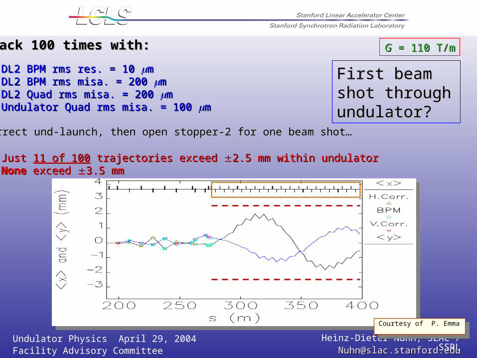
GG = 110 T/m = 110 T/mTrack 100 times with:Track 100 times with:
DL2 BPM rms res. = 10 DL2 BPM rms res. = 10 mmDL2 BPM rms misa. = 200 DL2 BPM rms misa. = 200 mmDL2 Quad rms misa. = 200 DL2 Quad rms misa. = 200 mmUndulator Quad rms misa. = 100 Undulator Quad rms misa. = 100 mm
Correct und-launch, then open stopper-2 for one beam shot…Correct und-launch, then open stopper-2 for one beam shot…
Just Just 11 of 10011 of 100 trajectories exceed trajectories exceed 2.5 mm within undulator2.5 mm within undulatorNoneNone exceed exceed 3.5 mm3.5 mm
First beam shot First beam shot through through undulator?undulator?
Courtesy of P. EmmaCourtesy of P. Emma

Undulator Physics April 29, 2004 Heinz-Dieter Nuhn, SLAC / SSRLFacility Advisory Committee Meeting [email protected]@slac.stanford.edu
Desirable measurements as function of position along undulator :
Intensity (LG, Saturation)
Spectral Distribution
Bunching
Desirable measurements as function of position along undulator :
Intensity (LG, Saturation)
Spectral Distribution
Bunching
FEL Gain MeasurementFEL Gain Measurement
Undulator RegimeUndulator Regime
Exponential Gain Regime
Exponential Gain Regime
Saturation
Saturation
1 % of X-Ray Pulse1 % of X-Ray Pulse
Electron BunchMicro-Bunching
Electron BunchMicro-Bunching

Undulator Physics April 29, 2004 Heinz-Dieter Nuhn, SLAC / SSRLFacility Advisory Committee Meeting [email protected]@slac.stanford.edu
Dose / Power ConsiderationsDose / Power Considerations
0.01
0.1
1
10
100
100 1000 10000
Photon energy (eV)
Flu
en
ce (
J/cm
^2
)
undulatorexitexperimentalhall A
experimentalhall B
C
Si
W
Au
Be
0.01
0.1
1
10
0.1 1 10 100
grazing angle (degrees)
energ
y d
ensit
y c
orr
ect
ion
0.8 keV critical angle
0.8 keV
8 keV critical angle
8 keV
with electroncorrection
no electroncorrection
Fluence to Melt
Energy Density Reduction of a
Reflector
Be will melt at normal incidence at E < 3 KeV near undulator exit.
Using Be as a grazing incidence reflector may gain x 10 in tolerance.
Courtesy of R. BiontaCourtesy of R. Bionta

Undulator Physics April 29, 2004 Heinz-Dieter Nuhn, SLAC / SSRLFacility Advisory Committee Meeting [email protected]@slac.stanford.edu
End-of-Undulator Commissioning DiagnosticsEnd-of-Undulator Commissioning Diagnostics
MeasurementsTotal energy
Pulse length
Photon energy spectra
Spatial coherence
Spatial shape and centroid
Divergence
MeasurementsTotal energy
Pulse length
Photon energy spectra
Spatial coherence
Spatial shape and centroid
Divergence

Undulator Physics April 29, 2004 Heinz-Dieter Nuhn, SLAC / SSRLFacility Advisory Committee Meeting [email protected]@slac.stanford.edu
Fastclosevalve
Slit A
PPS
13'Muonshield
Gas Attenuator
SolidAttenuator
Slit B
PPS
4'Muonshield
WindowlessIonChamber
Direct ImagerIndirect Imager
Spectrometer,Total Energy
PPS
AccessShaft
AccessShaft
Courtesy of R. BiontaCourtesy of R. Bionta
Undulator Physics April 29, 2004 Heinz-Dieter Nuhn, SLAC / SSRLFacility Advisory Committee Meeting [email protected]@slac.stanford.edu
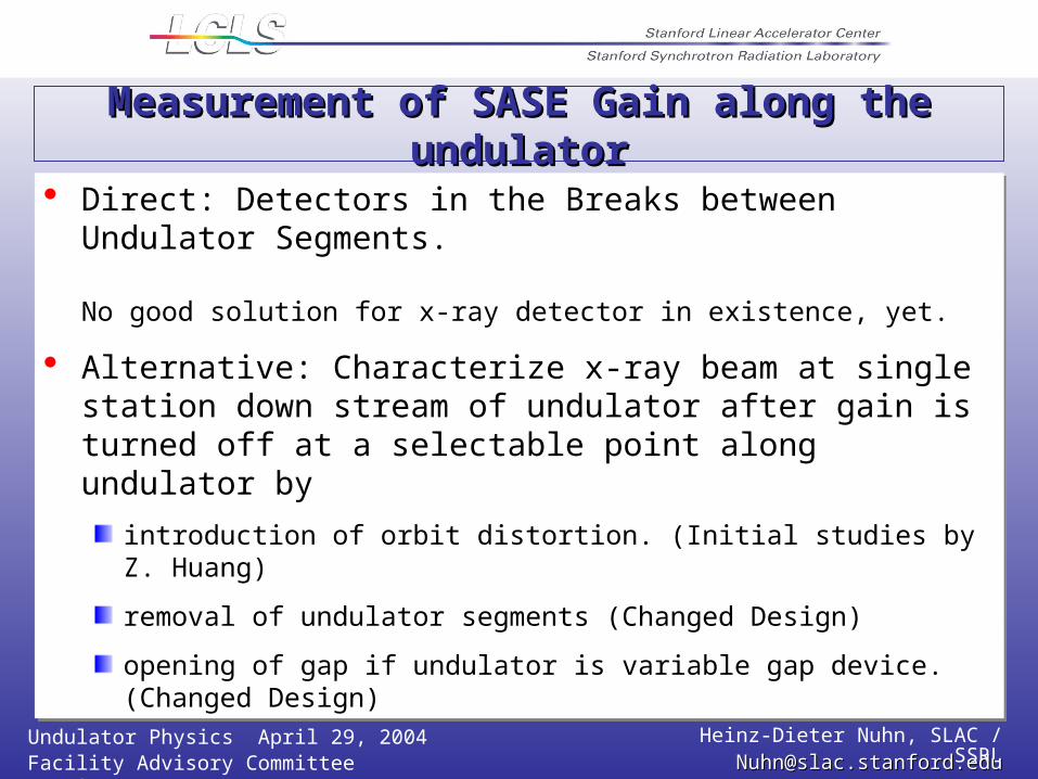
Measurement of SASE Gain along the undulatorMeasurement of SASE Gain along the undulator
Direct: Detectors in the Breaks between Undulator Segments.
No good solution for x-ray detector in existence, yet.
Alternative: Characterize x-ray beam at single station down stream of undulator after gain is turned off at a selectable point along undulator by
introduction of orbit distortion. (Initial studies by Z. Huang)
removal of undulator segments (Changed Design)
opening of gap if undulator is variable gap device. (Changed Design)

Undulator Physics April 29, 2004 Heinz-Dieter Nuhn, SLAC / SSRLFacility Advisory Committee Meeting [email protected]@slac.stanford.edu
Measurement of SASE Gain withMeasurement of SASE Gain withend-of-undulator diagnosticsend-of-undulator diagnostics
GENESIS Simulations by Z. Huang

Undulator Physics April 29, 2004 Heinz-Dieter Nuhn, SLAC / SSRLFacility Advisory Committee Meeting [email protected]@slac.stanford.edu
Spontaneous vs. FEL RadiationSpontaneous vs. FEL Radiation -1--1-
Figure by S. ReicheFigure by S. Reiche
Undulator Physics April 29, 2004 Heinz-Dieter Nuhn, SLAC / SSRLFacility Advisory Committee Meeting [email protected]@slac.stanford.edu
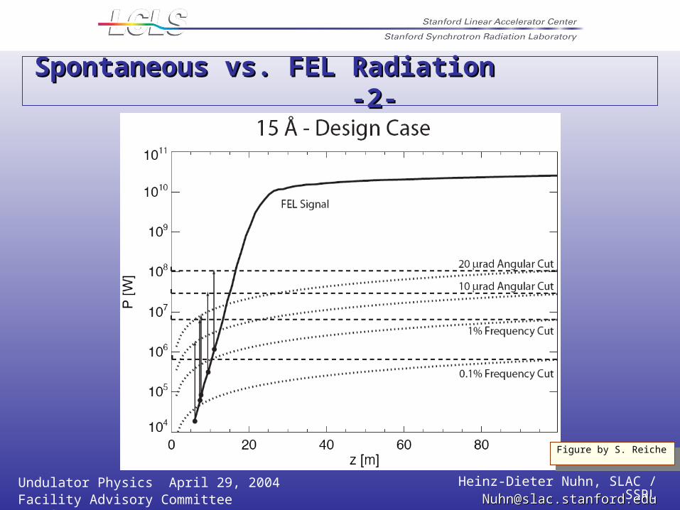
Spontaneous vs. FEL Radiation Spontaneous vs. FEL Radiation -2--2-
Figure by S. ReicheFigure by S. Reiche

Undulator Physics April 29, 2004 Heinz-Dieter Nuhn, SLAC / SSRLFacility Advisory Committee Meeting [email protected]@slac.stanford.edu
Startup at 15 Startup at 15 ÅÅ with highly degraded with highly degraded ee beam quality beam quality
FEL gain highly likely in initial commissioning stages – can check out undulator, characterize e beam, and boot-strap up to shorter wavelengths.
Undulator Physics April 29, 2004 Heinz-Dieter Nuhn, SLAC / SSRLFacility Advisory Committee Meeting [email protected]@slac.stanford.edu
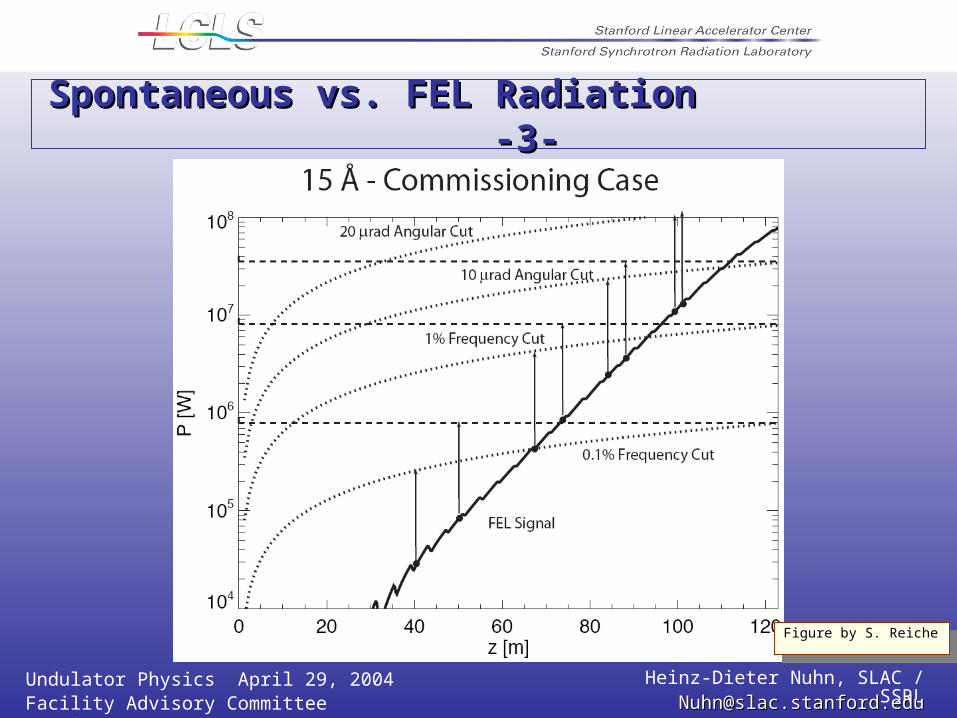
Spontaneous vs. FEL Radiation Spontaneous vs. FEL Radiation -3--3-
Figure by S. ReicheFigure by S. Reiche

Undulator Physics April 29, 2004 Heinz-Dieter Nuhn, SLAC / SSRLFacility Advisory Committee Meeting [email protected]@slac.stanford.edu
Workshop RecommendationsWorkshop Recommendations
No Intra-Undulator-Segment X-Ray Diagnostics in Baseline DesignInstead: End-of-Undulator X-Ray Diagnostics
CCD Camera (9 mm Pixel Resolution, 1024 x 1024 Area)Spectrometer
Trajectory Distortion Method to Characterize FEL Radiation vs. zInvestigation of Spontaneous Radiation as Diagnostics ToolsCode Development to Support CommissioningAreas for Follow-Up R&D
Study of Spectral and Spatial Distribution of Spontaneous RadiationDiagnostics PrototypingMicrobunching Measurement

Undulator Physics April 29, 2004 Heinz-Dieter Nuhn, SLAC / SSRLFacility Advisory Committee Meeting [email protected]@slac.stanford.edu
Draft Commissioning Schedule

Undulator Physics April 29, 2004 Heinz-Dieter Nuhn, SLAC / SSRLFacility Advisory Committee Meeting [email protected]@slac.stanford.edu
ConclusionsConclusions
Requirements for LCLS undulator are well established
LCLS undulator performance requirements are well understood
Risks have been assessed and undulator specifications address the risk
Commissioning plan is under development
Requirements for LCLS undulator are well established
LCLS undulator performance requirements are well understood
Risks have been assessed and undulator specifications address the risk
Commissioning plan is under development

Undulator Physics April 29, 2004 Heinz-Dieter Nuhn, SLAC / SSRLFacility Advisory Committee Meeting [email protected]@slac.stanford.edu
End of Presentation