underwater wireless communications for cooperative
TRANSCRIPT
applied sciences
Article
Underwater Wireless Communications forCooperative Robotics with UWSim-NET
Diego Centelles 1,* , Antonio Soriano-Asensi 2 , José Vicente Martí 1, Raúl Marín 1
and Pedro J. Sanz 1
1 Interactive Robotic Systems Lab, Universitat Jaume I, 12071 Castelló de la Plana, Spain2 Departament d’Informàtica–ETSE, Universitat de València, 46100 Burjassot, Spain* Correspondence: [email protected]
Received: 4 August 2019; Accepted: 24 August 2019; Published: 28 August 2019�����������������
Abstract: The increasing number of autonomous underwater vehicles (AUVs) cooperating inunderwater operations has motivated the use of wireless communications. Their modeling canminimize the impact of their limited performance in real-time robotic interventions. However, roboticframeworks hardly ever consider the communications, and network simulators are not suitablefor HIL experiments. In this work, the UWSim-NET is presented, an open source tool to simulatethe impact of communications in underwater robotics. It gathers the benefits of NS3 in modelingcommunication networks with those of the underwater robot simulator (UWSim) and the robotoperating system (ROS) in modeling robotic systems. This article also shows the results of threeexperiments that demonstrate the capabilities of UWSim-NET in modeling radio frequency (RF) andacoustic links in underwater scenarios. It also permits evaluating several MAC protocols such asadditive links online Hawaii area (ALOHA), slotted floor acquisition multiple access (S-FAMA) anduser defined protocols. A third experiment demonstrated the excellent capabilities of UWSim-NET inconducting hardware in the loop (HIL) experiments.
Keywords: underwater robotics; underwater communications; simulation; Hardware In The Loop
1. Introduction
Marine environments are not easy scenarios for human activities, especially when the operationshave to be performed at depths larger than 50 m. Underwater research is hampered by the requirementof developing waterproof and weight compensated devices, protected against high pressure. Despitethese limitations, the range of underwater applications continuously increases. Research onarchaeology or marine environment, maintenance and inspection of oil and gas infrastructures,and fish farming are some examples of human activities conducted at sea. Technological advanceshave enabled the automation of some of these activities, and also the cooperation of several devicesin order to conduct complex tasks. The rise of the number of devices employed in underwateractivities has motivated intense research in the field of underwater wireless networks to interconnectall these devices.
A current trend in robotic intervention is focused on cooperative applications with multipleremotely operated vehicles (ROV) or I-AUVs (Autonomous Underwater Vehicles for Intervention).For this, some robots conduct a given task while others perform additional activities, such asvisual surveying, to provide the operator with visual feedback of the progress of the operation.The communication between the ROVs or autonomous underwater vehicles (AUV) and the operatoris usually based on umbilical cables or acoustic transducers. While these approaches are valid inexperiments with a small number of vehicles, the participation of more and more robots in underwaterinterventions require novel solutions. In general, acoustic communications are a good solution for
Appl. Sci. 2019, 9, 3526; doi:10.3390/app9173526 www.mdpi.com/journal/applsci
Appl. Sci. 2019, 9, 3526 2 of 16
long range transmissions (>1000 m), but having several robots sharing the same acoustic channelmight degrade the performance of the communication link. Therefore, alternative solutions basedon radio frequency (RF) [1–3] are also considered for short range communications between ROVs.The problem with RF is the strong attenuation of electromagnetic signals in marine water, whichlimits the communication range to 15 m [4]. Visual light communication (VLC) [5–7] is anotheralternative that has a higher range than RF, but requires that the transmitter and the receiver arealigned. The communication link based on VLC is heavily influenced by water turbidity, being hard tooperate in dirty water.
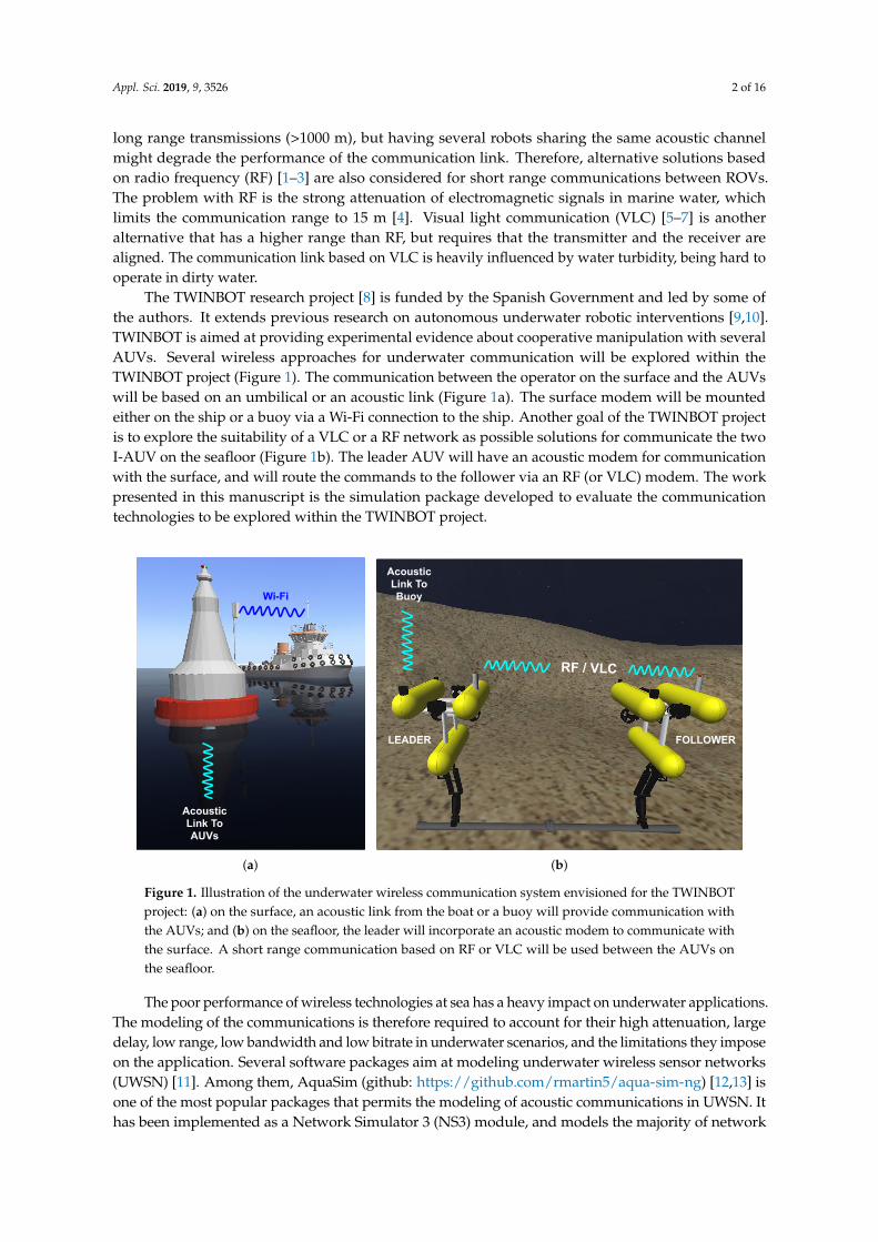
The TWINBOT research project [8] is funded by the Spanish Government and led by some ofthe authors. It extends previous research on autonomous underwater robotic interventions [9,10].TWINBOT is aimed at providing experimental evidence about cooperative manipulation with severalAUVs. Several wireless approaches for underwater communication will be explored within theTWINBOT project (Figure 1). The communication between the operator on the surface and the AUVswill be based on an umbilical or an acoustic link (Figure 1a). The surface modem will be mountedeither on the ship or a buoy via a Wi-Fi connection to the ship. Another goal of the TWINBOT projectis to explore the suitability of a VLC or a RF network as possible solutions for communicate the twoI-AUV on the seafloor (Figure 1b). The leader AUV will have an acoustic modem for communicationwith the surface, and will route the commands to the follower via an RF (or VLC) modem. The workpresented in this manuscript is the simulation package developed to evaluate the communicationtechnologies to be explored within the TWINBOT project.
Wi-Fi
Acoustic Link To AUVs
(a)
RF / VLC
Acoustic Link To Buoy
LEADER FOLLOWER
(b)
Figure 1. Illustration of the underwater wireless communication system envisioned for the TWINBOTproject: (a) on the surface, an acoustic link from the boat or a buoy will provide communication withthe AUVs; and (b) on the seafloor, the leader will incorporate an acoustic modem to communicate withthe surface. A short range communication based on RF or VLC will be used between the AUVs onthe seafloor.
The poor performance of wireless technologies at sea has a heavy impact on underwater applications.The modeling of the communications is therefore required to account for their high attenuation, largedelay, low range, low bandwidth and low bitrate in underwater scenarios, and the limitations they imposeon the application. Several software packages aim at modeling underwater wireless sensor networks(UWSN) [11]. Among them, AquaSim (github: https://github.com/rmartin5/aqua-sim-ng) [12,13] isone of the most popular packages that permits the modeling of acoustic communications in UWSN. Ithas been implemented as a Network Simulator 3 (NS3) module, and models the majority of network

Appl. Sci. 2019, 9, 3526 3 of 16
protocols, from physical to routing layers. Among the UWSN protocols implemented in AquaSim [14,15],the experiments in this manuscript consider CS-ALOHA and SFAMA that will be briefly describedlater in Section 2.2. The underwater acoustic network (UAN) framework is another module availablein NS3, which models the physical and link layers of acoustic communications in underwater networkscenarios, and also allows modeling AUVs. Its major limitation is the small number of medium accesscontrol (MAC) protocols that can be used CW-MAC [16], RC-MAC, and ALOHA. AquaSim permits ahigher variety of MAC protocols than UAN. However, they both only permit the modeling of acousticmodems. AquaSim and UAN are excellent tools for modeling UWSN with static nodes. They are able tomodel moving nodes, but the movement of the nodes is required to be defined in advance, before thesimulation starts, which strongly limits them to be considered as simulation tools in cooperative robotics.
Research in underwater environments requires that multiple hardware elements such asexperimentation platforms, sensors and modems are properly assembled, which have to work together.Tests at sea are not appropriate for experimentation during the assembly and evaluation stages becauseof the high number of devices involved. Spatial limitations in the laboratory also complicates theevaluation of the complete system. Hardware-in-the-Loop (HIL) experiments take a key role duringthe experimentation, since they permit evaluating some of the hardware devices while the remainingdevices are modeled by software. The underwater simulator (UWSim), developed by the authors [17],has proven to be an excellent tool in modeling underwater robots, and also as a Human-Robot Interface(HRI) in robotic experimentation.
In this work, we discuss some of the characteristics of UWSim-NET, an extension of UWSim formodeling the behavior of underwater wireless communications for a network of robots. UWSim-NETpermits modeling the physical and link layers of an underwater wireless communication system.It also permits evaluating several MAC protocols and to freely modify the position of the nodesduring the simulation in order to perform HIL tests. Some experiments conducted with UWSim-NETare also presented in order to show how it can be exploited to benefit the research community incommunications for underwater robotic swarms. The remainder of the manuscript is organized asfollows. The UWSim-NET is presented in Section 2, which details its architecture and the way theUWSim-NET elements are configured for each simulation. In Section 3, experiments demonstratingthe capabilities of the simulator are presented. Firstly, an experiment with two ROVs was performedto demonstrate the modeling of the properties of the physical layer such as the packet loss, collisions,propagation delay and FIFOs. The second experiment aimed to demonstrate the ability to comparedifferent MAC layers in a more complex scenario, such as in the case of the TWINBOT project. The lastexperiment consisted of the remote control of a team of cooperative robots in HIL (Hardware Inthe Loop), comparing the results of a teleoperation protocol over two MAC protocols. Finally, Section 4summarizes the most relevant contributions presented in this manuscript.
2. UWSim-NET
On the one hand, the tools used in robotics allow modeling the kinematics of the robots, but hardlyever account for the communications. On the other hand, there are excellent tools, such as NS3, thatpermit the modeling of communication networks [13]. However, NS3 simulations require the positionof communication nodes to be defined in advance, which hampers the realization of HIL experiments.UWSim [17] has been upgraded to model the behavior of underwater wireless communications fora network of robots. The new extension has been named UWSim-NET (github: https://github.com/uji-ros-pkg/underwater_simulation/tree/uwsimnet-devel) [18].
The main advantage of UWSim-NET is that it is a system integrated in Robotic Operating System(ROS) [19], thus it can not only to simulate the network, but also perform a complete simulation ofboth the robots and the network in real-time. The movements of the robots and packet flows can bepredefined before the start of the simulation as in UAN and AquaSim. UWSim-NET also allows theuser to move the devices during the simulation by calling the ROS API as well as permits real trafficsent by the user applications. These two characteristics are essential to conduct HIL experiments in
Appl. Sci. 2019, 9, 3526 4 of 16
order to test the modems or the user application as well as to model the modems and their impact onthe user application without needing to assemble real devices.
The simulation of the communications network in UWSim-NET is based on the real-time eventscheduler and other utilities of the NS3 library. It allows simulating both acoustic and custom modems.The modeling of acoustic devices is based on the NS3 module AquaSim NG [13], while RF andVLC devices are simulated as custom modems, based on a high-level statistical model that allowsadjusting its bit-rate, intrinsic jitter and delay. Thus, it can reproduce the performance of a realmodem. The custom device introduced in UWSim-NET allows modeling half and full duplex links.It also accounts for transmission errors caused by either signal attenuation or packet collisions. Theuser is able to define the behavior of a generic device by indicating the bitrate, the intrinsic delay,the jitter and the relationship of the bit error rate (BER) with the distance, which can be obtained fromexperimental measurements.
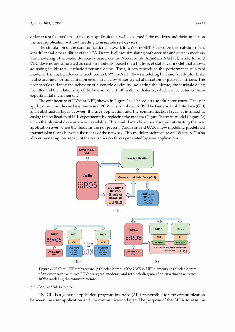
The architecture of UWSim-NET, shown in Figure 2a, is based on a modular structure. The userapplication module can be either a real ROV or a simulated ROV. The Generic Link Interface (GLI)is an abstraction layer between the user application and the communication layer. It is aimed ateasing the realization of HIL experiments by replacing the modem (Figure 2b) by its model (Figure 2c)when the physical devices are not available. This modular architecture also permits testing the userapplication even when the modems are not present. AquaSim and UAN allow modeling predefinedtransmission fluxes between the nodes of the network. This modular architecture of UWSim-NET alsoallows modeling the impact of the transmission fluxes generated by user applications.
UWSim-NET XML
Generic Link Interface (GLI)
DCComms Driver
For Real Device
DCCommsNetwork
Simulator based on
UWSim
User Application
(a)
UWSim-NET XML
UWSim
GLI
DCComms Driver
For Real Device
ROV 2
wirelesslink
GLI
DCComms Driver
For Real Device
ROV 1
(b)
UWSim-NET XML
UWSim
DCComms Network Simulator based on
GLI
ROV 1
modem
GLI
ROV 2
modem
(c)
Figure 2. UWSim-NET Architecture: (a) block diagram of the UWSim-NET elements; (b) block diagramof an experiment with two ROVs using real modems; and (c) block diagram of an experiment with twoROVs modeling the communications.
2.1. Generic Link Interface
The GLI is a generic application program interface (API) responsible for the communicationbetween the user application and the communication layer. The purpose of the GLI is to ease the
Appl. Sci. 2019, 9, 3526 5 of 16
realization of experiments either with a real device or with a modeled device with the UWSim-NET.The interchange of packets between the user application and the UWSim-NET in the GLI is basedon POSIX message queues [20]. To exchange messages between the user application and the modulein charge of sending the message (either the simulator or the driver of a real device), they are bothrequired to configure the same DCComms identifier.
2.2. DCComms Network Simulator
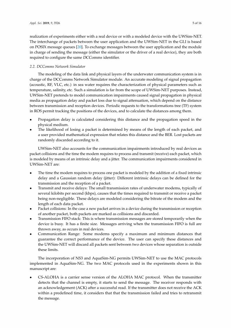
The modeling of the data link and physical layers of the underwater communication system is incharge of the DCComms Network Simulator module. An accurate modeling of signal propagation(acoustic, RF, VLC, etc.) in sea water requires the characterization of physical parameters such astemperature, salinity, etc. Such a simulation is far from the scope of UWSim-NET purposes. Instead,UWSim-NET pretends to model communication impairments caused signal propagation in physicalmedia as propagation delay and packet loss due to signal attenuation, which depend on the distancebetween transmission and reception devices. Periodic requests to the transformations tree (TF) systemin ROS permit tracking the positions of the devices, and to calculate the distances among them.
• Propagation delay is calculated considering this distance and the propagation speed in thephysical medium.
• The likelihood of losing a packet is determined by means of the length of each packet, anda user provided mathematical expression that relates this distance and the BER. Lost packets arerandomly discarded according to it.
UWSim-NET also accounts for the communication impairments introduced by real devices aspacket collisions and the time the modem requires to process and transmit (receive) each packet, whichis modeled by means of an intrinsic delay and a jitter. The communication impairments considered inUWSim-NET are:
• The time the modem requires to process one packet is modeled by the addition of a fixed intrinsicdelay and a Gaussian random delay (jitter): Different intrinsic delays can be defined for thetransmission and the reception of a packet.
• Transmit and receive delays: The small transmission rates of underwater modems, typically ofseveral kilobits per second (kbps), causes that the times required to transmit or receive a packetbeing non-negligible. These delays are modeled considering the bitrate of the modem and thelength of each data packet.
• Packet collisions: In the case a new packet arrives in a device during the transmission or receptionof another packet, both packets are marked as collisions and discarded.
• Transmission FIFO stack: This is where transmission messages are stored temporarily when thedevice is busy. It has a finite size. Messages arriving when the transmission FIFO is full arethrown away, as occurs in real devices.
• Communication Range: Some modems specify a maximum and minimum distances thatguarantee the correct performance of the device. The user can specify these distances andthe UWSim-NET will discard all packets sent between two devices whose separation is outsidethese limits.
The incorporation of NS3 and AquaSim-NG permits UWSim-NET to use the MAC protocolsimplemented in AquaSim-NG. The two MAC protocols used in the experiments shown in thismanuscript are:
• CS-ALOHA is a carrier sense version of the ALOHA MAC protocol. When the transmitterdetects that the channel is empty, it starts to send the message. The receiver responds withan acknowledgement (ACK) after a successful read. If the transmitter does not receive the ACKwithin a predefined time, it considers that that the transmission failed and tries to retransmitthe message.
Appl. Sci. 2019, 9, 3526 6 of 16
• SFAMA (Slotted Floor Acquisition Multiple Access) divides the time into slots of fixed duration.Slot duration is related with the delay at the maximum communication distance in order to preventthe overlap of RTS messages sent by different ROVs. At the beginning of a slot, the transmittersends a Request To Send (RTS) message and waits for the Clear To Send (CTS) message sent bythe receiver on the reception of CTS. Then, the transmitter starts to send a variable length DATAmessage. If the transmitter does not receive the CTS message, it assumes that a collision hashappened and waits for a number of slots (backoff) before the retransmission of the RTS.
2.3. UWSim-NET XML
All the information required for each experiment is specified by the user in the UWSim-NET XMLscene file, whose use is described in detail in [18]. As in UWSim, this file contains the vehicles andtheir initial positions. The communication channels and the communication devices on board eachvehicle are also indicated in the UWSim-NET XML file which includes the following sections:
• NetTracing Script: It is the block of the xml file that allows the user to specify the NetSimTracingclass with the callbacks that will handle NS3 events triggered by UWSim-NET, the library with itsimplementation and the name of the file where the logs will be stored.
• Communication Channels: Each channel, RF, VLC or acoustic, available in the scene will beconfigured in a CustomCommsChannel block of the xml file. For each channel in the scene, the useris expected to specify a unique identifier and the propagation speed.
• Communication Devices: They are defined in the block of the vehicle, or ROV, and are onboarded.Each vehicle can have as many communication devices as would be required. The user is requiredto indicate the DCComms identifier that has to coincide with that specified in the user applicationthat communicates with the device via the DCComms API. The user is also expected to providethe channel identifiers the device sends and receives messages, the bitrate, the jitter, the intrinsicdelay and the mathematical expression that relates the BER with the distance. The user can alsoselect the medium access control (MAC) protocol to be used by the device.
3. Results
Several experiments were performed to demonstrate the capabilities of UWSim-NET to modelthe communications of a group of underwater autonomous vehicles. First, an experiment with tworobots is presented to illustrate the communication mechanisms modeled in UWSim-NET. A secondexperiment simulating the teleoperation of two groups of robots is presented to demonstrate thecapabilities of UWSim-NET in modeling acoustic and RF communications and several MAC protocols.A final teleoperation experiment combining a real robot and three modeled robots illustrates thepossibility to conduct HIL experiments with UWSim-NET.
3.1. Physical Layer
The experiment shown in this section consisted of two robots moving away and approachingeach other. The block diagram of this experiment is shown in Figure 2c. It illustrated the packet lossdue to attenuation, and packet collisions when both robots try to transmit a message at the sametime. This experiment also showed the modeling of the transmission FIFO stacks. Both robots wereequipped with Seathooth S100 RF modems [21], by Wireless For Subsea. Packet loss was due to RFattenuation in sea water. The attenuation model used in this experiment was obtained empirically:BER = 6 10−13d13.7, being d the distance between devices (in meters). The maximum and minimumranges of the device were set to 6 m and 0.5 m, respectively.
The motion of the robots during the experiment is shown in Figure 3a. At the beginning of thesimulation, the distance between the ROVs was 80 cm. They held the position for 11 s, and then one ofthe ROVs moved away from the other at a constant speed of 0.25 m/s for 20 s. To ensure that the loss ofpackets was due to attenuation and to avoid packet collisions, only one ROV transmitted while the other

Appl. Sci. 2019, 9, 3526 7 of 16
received the packets. The moving ROV returned at the same speed for 5 s and held the position at 4.5 mfor 10 s. Then, it moved again towards the fixed robot for 5 s at 0.25 m/s and held the position at 3.3 m.To show the packet collision, the second ROV transmitted during Seconds 37–58 during its return.
10 20 30 40 50 60Time (s)
0
1
2
3
4
5
Dis
tanc
e (m
)
(a)
10 20 30 40 50 60Time (s)
rx
rx
rx
rx
tx
Even
t Ty
pe
tx rx err(PROP) err(COL) err(MULT)
(b)
10 20 30 40 50 60Time (s)
rx
rx
rx
rx
tx
Even
t Ty
pe
tx rx err(PROP) err(COL) err(MULT)
(c)
10 20 30 40 50 60Time (s)
0
10
20
30
40
50
FIFO
Siz
e (B
)
n0 n1
(d)
Figure 3. Collision of packets when two ROVs are transmitting at the same time. Transmitted packets(tx), successfully received packets (rx), packets lost due to attenuation (err(PROP)), packets lost dueto collision (err(COL)) and packets that have suffered attenuation and collision (err(MULT)) arepresented: (a) distance between the ROVs during the experiment; (b) flux of packets of the ROV thatis transmitting continuously; (c) flux of packets of the ROV that starts a transmission while the otherROV is transmitting; and (d) occupation of the transmission FIFO stack.
Figure 3b,c shows transmitted (blue dots), received (green dots) and lost (black, red and orangedots) packets when two transmission fluxes were considered from node 0 to node 1 and from node 1to node 0, respectively. Different colors are used to illustrate the packet loss mechanism. The packets
Appl. Sci. 2019, 9, 3526 8 of 16
dropped because of attenuation are marked in black, while red dots correspond to those that sufferedcollision. The ones that suffered both attenuation and collision are shown in orange. When the secondrobot started its transmission at Second 37, when the distance between the ROVs was about 4.5 mboth, signal attenuation and collision mechanisms occurred. However, as the second ROV approached,no packets suffered from attenuation, and loses were due to packet collision.
The results shown in Figure 3b illustrate the continuous transmission, and how most of the packetswere successfully transmitted. As the second ROV started to transmit (see Figure 3c), it is appreciatedin both figures how many packets suffered collisions. The number of successfully transmitted packetswas small in both fluxes. As the second ROV stopped sending packets, the situation of the transmissionflux, as shown in Figure 3b, returned to the original situation. Both ROVs were configured to transmitat 1500 bps, which is close to the 1800 bps maximum bitrate of the modems. When both ROVs weretransmitting, some packets were stored in the transmission FIFO, as can be seen in Figure 3d.
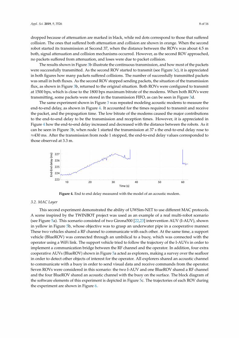
The same experiment shown in Figure 3 was repeated modeling acoustic modems to measure theend-to-end delay, as shown in Figure 4. It accounted for the times required to transmit and receivethe packet, and the propagation time. The low bitrate of the modems caused the major contributionsto the end-to-end delay to be the transmission and reception times. However, it is appreciated inFigure 4 how the end-to-end delay increased and decreased with the distance between the robots. As itcan be seen in Figure 3b, when node 1 started the transmission at 37 s the end-to-end delay rose to≈430 ms. After the transmission from node 1 stopped, the end-to-end delay values corresponded tothose observed at 3.3 m.
10 20 30 40 50 60Time (s)
223
224
225
226
227
End
-End
del
ay (m
s)
Figure 4. End to end delay measured with the model of an acoustic modem.
3.2. MAC Layer
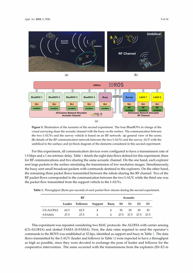
This second experiment demonstrated the ability of UWSim-NET to use different MAC protocols.A scene inspired by the TWINBOT project was used as an example of a real multi-robot scenario(see Figure 5a). This scenario consisted of two Girona500 [22,23] intervention AUV (I-AUV), shownin yellow in Figure 5b, whose objective was to grasp an underwater pipe in a cooperative manner.These two vehicles shared a RF channel to communicate with each other. At the same time, a supportvehicle (BlueROV) was connected through an umbilical to a buoy, which was connected with theoperator using a WiFi link. The support vehicle tried to follow the trajectory of the I-AUVs in order toimplement a communication bridge between the RF channel and the operator. In addition, four extracooperative AUVs (BlueROV) shown in Figure 5a acted as explorers, making a survey over the seafloorin order to detect other objects of interest for the operator. All explorers shared an acoustic channelto communicate with a buoy in order to send visual data and receive commands from the operator.Seven ROVs were considered in this scenario: the two I-AUV and one BlueROV shared a RF channeland the four BlueROV shared an acoustic channel with the buoy on the surface. The block diagram ofthe software elements of this experiment is depicted in Figure 5c. The trajectories of each ROV duringthe experiment are shown in Figure 6.
Appl. Sci. 2019, 9, 3526 9 of 16
RF Channel
Umbilical
AcousticChannel
(a)
RF Channel
Umbilical
(b)
GLI
UWSim
DCComms Network SimulatorAcoustic Channel
modem
BlueROV 3 BlueROV 4 I-AUV 1 I-AUV 2
DCComms Network SimulatorRF Channel
modem modem modem RFmodem
RFmodem
RFmodem
BlueROV 2
modem
GLI GLI GLI GLI GLIGLI
BlueROV 1
GLI
umbilical SurveyBuoy
(c)
Figure 5. Illustration of the scenario of the second experiment. The four BlueROVs in charge of thevisual surveying share the acoustic channel with the buoy on the surface. The communication betweenthe two I-AUVs and the survey vehicle is based on an RF network: (a) general view of the scene;(b) details of the RF communication network between the two I-AUVs and the survey AUV with theumbilical to the surface; and (c) block diagram of the elements considered in this second experiment.
For this experiment, all communication devices were configured to have a transmission rate of1.9 kbps and a 1 ms intrinsic delay. Table 1 details the eight data flows defined for this experiment, threefor RF communications and five sharing the same acoustic channel. On the one hand, each explorersent large packets to the surface simulating the transmission of low resolution images. Simultaneously,the buoy sent small broadcast packets with commands destined to the explorers. On the other hand,the remaining three packet flows transmitted between the robots sharing the RF channel. Two of theRF packet flows corresponded to the communication between the two I-AUV, while the third one wasthe packet flow transmitted from the support vehicle to the I-AUVs.
Table 1. Throughput (Bytes per second) of each packet flow stream during the second experiment.
RF Acoustic
Leader Follower Support Buoy E0 E1 E2 E3
CS-ALOHA 62.5 62.5 4 4 30 30 30 30
S-FAMA 27.5 27.5 4 4 27.5 27.5 27.5 27.5
This experiment was repeated considering two MAC protocols: the ALOHA with carrier sensing(CS-ALOHA) and slotted FAMA (S-FAMA). First, the data rates required to send the operator’scommands to the ROVS was established at 32 bps, identified as support and buoy in Table 1. The dataflows transmitted by the I-AUV (leader and follower in Table 1) were expected to have a throughputas high as possible, since they were devoted to exchange the pose of leader and follower for thecooperative intervention. The same occurred with the transmissions from the explorers (E0–E3 in

Appl. Sci. 2019, 9, 3526 10 of 16
Table 1), which were expected to provide the operator with visual feedback of the seafloor, thus to adjustthe data rate of each transmission at the maximum value allowed for each protocol. The resulting datarates for each experiment are shown in Table 1. To illustrate the relevance of the MAC layer, the sameexperiment was done without considering any MAC protocol. The data flows were configured as withthe CS-ALOHA.
(a) (b)
(c)
Figure 6. Trajectories followed by the ROVs during the experiment. The trajectories of the explorers arerepresented in white lines. The lines in yellow and red correspond to the trajectories of the two I-AUVs,and the line in magenta corresponds to the support ROV. Each image corresponds to a different stageof the experiment: (a) approaching; (b) cooperative grasping; and (c) transportation.
The performance achieved with each MAC protocol was compared in terms of throughput,efficiency, end-to-end delay and jitter. As expected, the throughput measured after the experiment(see Figure 7a), coincided with the values indicated in Table 1. However, when no MAC protocol wasconsidered, only the data flows transmitted by the support, buoy and E2 succeeded in sending packets.The efficiency is the ratio of bytes successfully received to the total number of transmitted bytes. It isrelated with the power consumption of the communications system. It is appreciated in Figure 7bthat the S-FAMA had a higher efficiency than CS-ALOHA in the acoustic channel, but the oppositeoccurred with RF channel between the I-AUVs and the support. This behavior might be understoodconsidering the two different sizes of the packets used in each flux: data packets transmitted by leader,follower, support and buoy were 20 bytes long, but the image packets transmitted by the explorerswere 400 bytes long. The less overhead of the CS-ALOHA, the smaller number of nodes in the RF

Appl. Sci. 2019, 9, 3526 11 of 16
channel and the small likelihood of small packets to collide favored the better results observed withthe CS-ALOHA. On the contrary, the larger packet sizes and the higher number of nodes favored thebetter performance of the S-FAMA in the acoustic channel. When no MAC protocol was considered,no positive results were obtained because very few packets were successfully transmitted and theefficiency was near zero.
The end-to-end delay (Figure 7c), and jitter (Figure 7d) are related with the time lapse required tosend the information between the ROVs. In general, S-FAMA achieved a lower end-to-end delay thanCS-ALOHA (see Figure 7c). The low end-to-end delay achieved when no MAC protocol was usedwas due to the very low number of successfully transmitted packets. If the transmission succeeded,the packet was delivered immediately, and it had little contribution to the end-to-end delay. Concerningthe jitter, comparable results were obtained with both protocols.
0
20
40
60
80
Leader
Follower
Support Bu
oy E0 E1 E2 E3
NOMAC ALOHA SFAMA
(a)
0
25
50
75
100
Leader
Follower
Support Bu
oy E0 E1 E2 E3
NOMAC ALOHA SFAMA
(b)
0
2
4
6
8
Leader
Follower
Support Bu
oy E0 E1 E2 E3
NOMAC ALOHA SFAMA
(c)
0
1
2
3
4
5
Leader
Follower
Support Bu
oy E0 E1 E2 E3
NOMAC ALOHA SFAMA
(d)
Figure 7. Results for the TWINBOT based scenario without considering any MAC protocol (NOMAC),considering CS-ALOHA MAC protocol (ALOHA) and the S-FAMA MAC protocol (SFAMA), in termsof: (a) throughput (bytes per second); (b) efficiency (%); (c) end-to-end delay (s); and (d) jitter (s).
3.3. Remote ROV Team Control in HIL
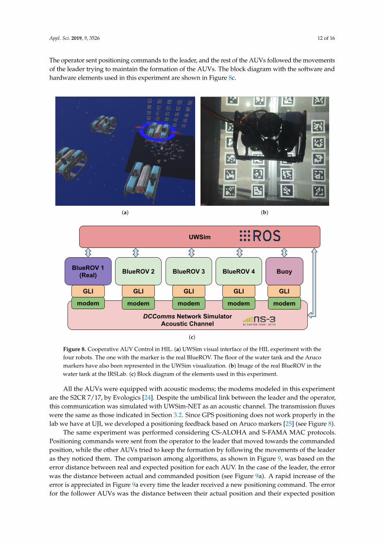
The third experiment presented in this paper demonstrated the capability of UWSim-NET inperforming HIL experiments. It corresponded to the four exploration AUVs detailed in Section 3.2.The four AUVs were arranged in a squared formation and the distance between adjacent vehicles was1.5 m. The leader AUV was replaced by a real BlueROV; it is identified with the marker in Figure 8.
Appl. Sci. 2019, 9, 3526 12 of 16
The operator sent positioning commands to the leader, and the rest of the AUVs followed the movementsof the leader trying to maintain the formation of the AUVs. The block diagram with the software andhardware elements used in this experiment are shown in Figure 8c.
(a) (b)
GLI
UWSim
DCComms Network SimulatorAcoustic Channel
modem
BlueROV 3 BlueROV 4
modem modem modem
BlueROV 2
modem
GLI GLI GLIGLI
BlueROV 1(Real) Buoy
(c)
Figure 8. Cooperative AUV Control in HIL. (a) UWSim visual interface of the HIL experiment with thefour robots. The one with the marker is the real BlueROV. The floor of the water tank and the Arucomarkers have also been represented in the UWSim visualization. (b) Image of the real BlueROV in thewater tank at the IRSLab. (c) Block diagram of the elements used in this experiment.
All the AUVs were equipped with acoustic modems; the modems modeled in this experimentare the S2CR 7/17, by Evologics [24]. Despite the umbilical link between the leader and the operator,this communication was simulated with UWSim-NET as an acoustic channel. The transmission fluxeswere the same as those indicated in Section 3.2. Since GPS positioning does not work properly in thelab we have at UJI, we developed a positioning feedback based on Aruco markers [25] (see Figure 8).
The same experiment was performed considering CS-ALOHA and S-FAMA MAC protocols.Positioning commands were sent from the operator to the leader that moved towards the commandedposition, while the other AUVs tried to keep the formation by following the movements of the leaderas they noticed them. The comparison among algorithms, as shown in Figure 9, was based on theerror distance between real and expected position for each AUV. In the case of the leader, the errorwas the distance between actual and commanded position (see Figure 9a). A rapid increase of theerror is appreciated in Figure 9a every time the leader received a new positioning command. The errorfor the follower AUVs was the distance between their actual position and their expected position

Appl. Sci. 2019, 9, 3526 13 of 16
based on the actual position of the leader. As expected, a rapid increase of the error can be appreciatedin Figure 9b–d when the leader moved. As appreciated in Figure 8, comparable performance wasachieved when CS-ALOHA and S-FAMA MAC protocols were considered.
50 100 150 200Time (s)
0
1
Erro
r (m
)
Leader-ALOHA Leader-SFAMA
(a)
50 100 150 200Time (s)
0
1
Erro
r (m
)
F0-ALOHA F0-SFAMA
(b)
50 100 150 200Time (s)
0
1
Erro
r (m
)
F1-ALOHA F1-SFAMA
(c)
50 100 150 200Time (s)
0
1
Erro
r (m
)
F2-ALOHA F2-SFAMA
(d)
Figure 9. Waypoint distance error for each AUV for the CS-ALOHA and S-FAMA MAC protocols.(a) Distance between commanded position and actual position of the leader. Distance between actualposition and expected position based on leader’s for: (b) the AUV on the left of the leader; (c) the AUVplaced back and left; and (d) the AUV placed behind the leader.

Appl. Sci. 2019, 9, 3526 14 of 16
4. Conclusions
Devices for underwater wireless communications suffer from small bandwidth, high attenuationand large delay. The modeling of these systems might contribute to minimize the impact of theirlimited performance in cooperative robotic applications. On the one hand, software applicationsused in robotics such as ROS hardly ever account for the modeling of the communications. On theother hand, network simulators such as NS3 require the user to define in advance all the fluxes andthe movements of the nodes during the modeling, which hampers their use in HIL experiments.This manuscript introduces UWSim-NET, an extension of UWSim that permits the modeling ofunderwater communications for wireless sensors and robots (e.g., AUVs). The modeling of thedynamics of the robots is based on UWSim and ROS, while the communication network is modeledusing the NS3. A modular architecture is proposed for UWSim-NET. One of the modules is a GenericLink Interface, which acts as an abstraction layer for the devices. This module facilitates the replacementof real and modeled communication devices, and also permits HIL experimentation.
Three experiments are presented in this article to demonstrate the capabilities of UWSim-NET inmodeling communication impairments, allowing RF and acoustic channels, modeling several MACprotocols and performing HIL experiments (see Table 2). The first one modeled an RF and an acousticlink between two robots, and showed the capabilities of UWSim-NET in modeling losses by signalattenuation or packet collisions. The measurement of end-to-end delay and the modeling of thetransmission FIFO stack of the modems were also illustrated in this first experiment. The secondexperiment was the simulation of a search and recovery intervention with autonomous vehicles.The experiment was composed of two groups of three and four AUVs, respectively. The first group ofrobots, in charge of the intervention, was equipped with RF modems, while the second group was incharge of the search, communicating with acoustic devices. Efficiency, throughput, end-to-end delayand jitter were evaluated when using teh CS-ALOHA and S-FAMA MAC protocols. The results ofthis experiment demonstrate the relevance of the MAC protocol, and that, depending on the trafficcharacteristics, a given protocol or another might be preferable. In the third experiment, one of the fourBlueROVs modeled in the second experiment was substituted by a real BlueROV. The performanceof the supervised remote control was assessed by measuring the distance between expected and realpositions of each robot. This experiment demonstrated the capability of UWSim-NET in performingHIL trials.
Table 2. Summary of the main findings of each experiment.
Experiment Description Findings
Physical Layer Two moving AUVs sending data atthe same time
Demonstration of the correct modeling ofend-to-end delay, packet loss, packet collisions andthe transmission FIFOs.
MAC layerCooperative intervention with 4AUVs sharing an acoustic channeland 3 I-AUVs sharing an RF channel.
Demonstration of the capability of UWSim-NET tomodel acoustic and RF devices, and the possibilityto use different MAC protocols.
HILTeleoperation of 4 AUVs, one ofthem being a real BlueROV ina water tank
Demonstration of the capability of UWSim-NET toperform HIL experiments in a real application, inwhich the positions of the AUVs vary arbitrarilyduring the experiment.
Appl. Sci. 2019, 9, 3526 15 of 16
Author Contributions: Conceptualization, R.M. and P.J.S.; methodology, J.V.M.; software D.C.; validation, R.M.;formal analysis, D.C. and A.S.-A.; investigation, D.C.; resources, J.V.M.; data curation, D.C.; writing—originaldraft preparation, D.C. and A.S.-A.; writing—review and editing, D.C., A.S.-A. and R.M.; visualization, D.C. andA.S.-A.; supervision, R.M.; project administration, P.J.S.; and funding acquisition, R.M. and P.J.S.
Funding: This research was partially funded by the Spanish Government under under grants BES-2015-073112,DPI2014-57746-C3 (MERBOTS), and DPI2017-86372-C3 (TWINBOT); Generalitat Valenciana under Prometeoprogram; and Jaume I University under NEPTUNO project.
Conflicts of Interest: The authors declare no conflict of interest.
Abbreviations
The following abbreviations are used in this manuscript:
API Application Program InterfaceAUV Autonomous Underwater VehicleBER Bit Error RateCS-ALOHA Carrier Sense—Additive Links Online Hawaii AreaCTS Clear To SendFIFO First Input First OutputGLI Generic Link InterfaceGPS Global Positioning SystemHIL Hardware In the LoopHRI Human Robot InterfaceI-AUV Intervention Autonomous Underwater VehicleMAC Medium Access ControlNS3 Network Simulator 3RF Radio FrequencyROS Robotic Operating SystemROV Remotely Operated VehicleRTS Request To SendS-FAMA Slotted Floor Acquisition Multiple AccessUAN Underwater Acoustic NetworkUWSim UnderWater SimmulatorUSWim-NET UnderWater Simulator with Network modelingUWSN Underwater Wireless Sensor NetworkVLC Visual Light Communications
References
1. Che, X.; Wells, I.; Dickers, G.; Kear, P.; Gong, X. Re-Evaluation of RF Electromagnetic Communication inUnderwater Sensor Networks. IEEE Commun. Mag. 2010, 48, 143–151. [CrossRef]
2. Dea, J.; Radosevic, D.; Tran, N.; Chavez, J.; Neuner III, B. Land and Undersea Field Testing of Very Low FrequencyRF Antennas and Loop Transceivers; Technical Report; SSC Pacific: San Diego, CA, USA, 2017.
3. Shaw, A.; Al-Shamma’a, A.; Wylie, S.; Toal, D. Experimental Investigations of Electromagnetic WavePropagation in Seawater. In Proceedings of the 2006 European Microwave Conference, 36th European,Manchester, UK, 10–15 September 2006; pp. 572–575. [CrossRef]
4. Wireless for Subsea. Datasheet of Seatooth S100-L Wireless Subsea Controller. Technical Report. Availableonline: http://www.wfs-tech.com/wp-content/uploads/2017/11/Seatooth-S100-L-Extended-Range-17.11.1.pdf (accessed on 27 August 2019)
5. Kaushal, H.; Kaddoum, G. Underwater Optical Wireless Communication. IEEE Access 2016, 4, 1518–1547.[CrossRef]
6. Farr, N.; Bowen, A.; Ware, J.; Pontbriand, C.; Tivey, M. An integrated, underwater optical /acousticcommunications system. In Proceedings of the OCEANS 2010 IEEE, Sydney, NSW, Australia, 4–27 May2010; pp. 1–6. [CrossRef]
Appl. Sci. 2019, 9, 3526 16 of 16
7. Cossu, G.; Corsini, R.; Khalid, A.; Balestrino, S.; Coppelli, A.; Caiti, A.; Ciaramella, E. Experimentaldemonstration of high speed underwater visible light communications. In Proceedings of the 2013 2ndInternational Workshop on Optical Wireless Communications (IWOW), Newcastle upon Tyne, UK, 21–21October 2013; pp. 11–15. [CrossRef]
8. IRSLab. TWINBOT Research Project. 2018. Available online: http://www.irs.uji.es/twinbot/ (accessed on27 August 2019).
9. MERBOTS Research Project. Available online: http://www.irs.uji.es/merbots/ (accessed on 27 August 2019).10. Ribas, D.; Ridao, P.; Turetta, A.; Melchiorri, C.; Palli, G.; Fernandez, J.J.; Sanz, P.J. I-AUV Mechatronics
Integration for the TRIDENT FP7 Project. IEEE/ASME Trans. Mechatronics 2015, 20, 2583–2592. [CrossRef]11. Das, A.P.; Thampi, S.M. Simulation tools for underwater sensor networks: a survey. Netw. Protoc. Algorithms
2017, 8, 41–55. [CrossRef]12. Xie, P.; Zhou, Z.; Peng, Z.; Yan, H.; Hu, T.; Cui, J.; Shi, Z.; Fei, Y.; Zhou, S. Aqua-Sim: An NS-2 based
simulator for underwater sensor networks. In Proceedings of the OCEANS 2009, Biloxi, MS, USA, 26–29October 2009; pp. 1–7. [CrossRef]
13. Martin, R.; Rajasekaran, S.; Peng, Z. Aqua-Sim Next Generation: An NS-3 Based Underwater SensorNetwork Simulator. In Proceedings of the International Conference on Underwater Networks & Systems,WUWNET’17, Halifax, NS, Canada, 6–8 November 2017; ACM: New York, NY, USA, 2017; pp. 3:1–3:8.[CrossRef]
14. Heidemann, J.; Stojanovic, M.; Zorzi, M. Underwater sensor networks: applications, advances and challenges.Philos. Trans. R. Soc. Lond. Math. Phys. Eng. Sci. 2012, 370, 158–175. Available online: http://xxx.lanl.gov/abs/http://rsta.royalsocietypublishing.org/content/370/1958/158.full.pdf (accessed on 27 August 2019).[CrossRef] [PubMed]
15. Ayaz, M.; Baig, I.; Abdullah, A.; Faye, I. Review: A Survey on Routing Techniques in Underwater WirelessSensor Networks. J. Netw. Comput. Appl. 2011, 34, 1908–1927. [CrossRef]
16. Parrish, N.; Tracy, L.; Roy, S.; Arabshahi, P.; Fox, W. System Design Considerations for Undersea Networks:Link and Multiple Access Protocols. IEEE J. Sel. Areas Commun. 2008, 26, 1720–1730. [CrossRef]
17. Prats, M.; Pérez, J.; Fernández, J.; Sanz, P. An open source tool for simulation and supervision of underwaterintervention missions. In Proceedings of the 2012 IEEE/RSJ International Conference on Intelligent Robotsand Systems, Vilamoura, Portugal, 7–12 October 2012; pp. 2577–2582. [CrossRef]
18. Centelles, D.; Soriano, A.; Martí, J.V.; Marın, R.; Sanz, P.J. UWSim-NET: An open-source framework forexperimentation in communications for underwater robotics. In Proceedings of the IEEE Oceans Conference2019, Marseille, France, 17–20 June 2019.
19. Quigley, M.; Conley, K.; Gerkey, B.; Faust, J.; Foote, T.; Leibs, J.; Wheeler, R.; Ng, A.Y. ROS: An open-sourceRobot Operating System. In Proceedings of the ICRA Workshop on Open Source Software, Kobe, Japan, 12May 2009; Volume 3, p. 5.
20. Immich, P.K.; Bhagavatula, R.S.; Pendse, D.R. Performance analysis of five interprocess communicationmechanisms across UNIX operating systems. J. Syst. Softw. 2003, 68, 27–43. [CrossRef]
21. Wireless for Subsea. Datasheet of Seatooth S100 Wireless Subsea Controller. Technical Report.Atailable online: http://www.wfs-tech.com/wp-content/uploads/2017/06/Seatooth-S100-17.-01.-1.pdf(27 August 2019).
22. Ribas, D.; Palomeras, N.; Ridao, P.; Carreras, M.; Mallios, A. Girona 500 AUV: From Survey to Intervention.Mechatronics IEEE/Asme Trans. 2012, 17, 46–53. [CrossRef]
23. Palomeras, N.; El-Fakdi, A.; Carreras, M.; Ridao, P. COLA2: A Control Architecture for AUVs. IEEE J. Ocean.Eng. 2012, 37, 695–716. [CrossRef]
24. Evologics. Datasheet of S2C R 7/17 Underwater Acoustic Modem. Technical Report. Available online:https://evologics.de/acoustic-modem/7-17/r-serie#downloads (27 August 2019).
25. Garrido-Jurado, S.; Muñoz-Salinas, R.; Madrid-Cuevas, F.; Marín-Jiménez, M. Automatic generationand detection of highly reliable fiducial markers under occlusion. Pattern Recognit. 2014, 47, 2280–2292.[CrossRef]
c© 2019 by the authors. Licensee MDPI, Basel, Switzerland. This article is an open accessarticle distributed under the terms and conditions of the Creative Commons Attribution(CC BY) license (http://creativecommons.org/licenses/by/4.0/).