understanding water and unconventional resources
TRANSCRIPT

Understanding Water and Unconventional Resources

2
Why does the oil and gas industry need water?
Drilling boreholes deep into the ground and preparing them to produce oil or gas is a highly technical and specialized process. Throughout the entire operation, custom-designed water-based fluids fulfill many different roles. While drilling, these include:
• lubricating the drill bit;• circulating drilled-up rock out of the
hole;• containing formation fluids within the
hole; and• facilitating operation of sophisticated
formation evaluation tools
While preparing the well to produce oil or gas (“completing” the well) by hydraulic fracturing, these roles include:
• transmitting pressure downhole to create fractures in the rock;
• carrying proppant (usually sand) into the formation to hold fractures open
Typical Drill Bit
A hydraulic fracturing unit can pump fluids at high pressure into the wellbore, through the perforations and into the targeted formation.
Source: Trican Well Service
This booklet discusses the unconventional oil and gas industry’s use, production and protection of water resources. For more information about hydraulic fracturing techniques, please reference Understanding Hydraulic Fracturing and Understanding Shale Gas in Canada at www.csur.com.

3
Background
Drilling operations typically need only modest volumes of water – oil and gas wellbores can hold only tens of cubic metres of fluid, and these are circulated and recycled efficiently during drilling operations.
Hydraulic fracturing operations in unconventional resources that use water as the primary fracturing fluid, particularly in horizontal wells, can require tens of thousands of cubic metres of water. These large volumes of water are needed because, in horizontal wells, multiple fracturing stages are conducted. Fracturing fluids are needed at each stage of the process in order to convey the pressures necessary to stimulate each section of the length of the lateral and to carry the proppant material into the newly created fractures.
Hydraulic fracturing is not a new process and has been used safely by the oil and gas industry for more than 60 years. Recent advancements in technology have unlocked previously unattainable
sources of natural gas present within lower quality reservoirs that characterize unconventional resources.
As hydraulic fracturing techniques have evolved, so too have the regulations which protect water resources, the environment and public. Enhancements to existing regulations will continue to ensure the responsible development of unconventional hydrocarbon resources.
Multiple fracture stages along a horizontal wellbore

4
Why are the water requirements different for unconventional resource plays than for conventional operations?Conventional reservoirs usually have sufficient natural permeability to allow oil or gas to move to a wellbore, at rates high enough to be economic, with little or no stimulation. In other words, the oil and gas volume produced is of sufficient quantity to pay for the costs of drilling and development, and to generate some return on the investment to the operator.
Unconventional reservoirs have low natural permeability – even though they contain abundant oil and gas, low productivity usually limits the economic viability. Some unconventional reservoirs cannot produce oil or gas at all, prior to fracturing, because their permeability is so low. In Image 1, the green pathways would not be present in an unconventional reservoir. Modern drilling and completions technologies expose and connect sufficient permeability in unconventional reservoirs to generate economic flow rates of oil or gas. This is accomplished by using one or both of two techniques. Horizontal drilling which involves drilling wellbores down to the oil or gas-bearing formation and then turning the bit and pipe (termed the kick-off point) to drill horizontally through the reservoir so that the wellbore is in contact with a long section of oil or gas-bearing rock.
Image 1: Typical permeable conventional reservoir
Image 2: Drilling of a horizontal well

5
Hydraulic fracturing procedures may then be conducted at different intervals along the horizontal wellbore, opening existing fracture pathways or creating new ones within the reservoir rock. This process is referred to as “stimulation” and results in the creation of sufficient permeability to allow economic hydrocarbon flow rates.
Many of the unconventional reservoirs now being developed, particularly shales, must be accessed using horizontal wellbores which can be more than a kilometre in length and may require more than 20 fracture stimulations or “frac jobs” in order to be economically successful. Large quantities of water, or other fluid, are key to unconventional resource development – much larger quantities than are required for most conventional developments.
The image to the right shows two (2) fracture stimulations;
the darkened fractures were completed as one stage and
are now temporarily isolated while those shown in yellow are occurring as the next stage . The
number of fractures required in a wellbore will vary based on
the characteristics of the target formation.

6
Where can the oil and gas industry obtain water?
Source Typical Depth (m) TDS (mg/l) Suitable Uses Availability
Surface Water Rivers 0 Less than 4,000 Rural/Agriculture, Industrial Variable
Lakes 0 Less than 4,000 Rural/Agriculture, Industrial Variable
Run-off 0 Less than 4,000 Rural/Agriculture, Industrial Variable
Shallow Subsurface Aquifer Unconsolidated sands & gravel Less than 300 Less than 4,000 Rural/Agriculture, Industrial Variable
Coal Seams Less than 300 Less than 4,000 Rural/Agriculture, Industrial Variable
Sandstones Less than 300 Less than 4,000 Rural/Agriculture, Industrial Variable
Municipal Supply Less than 300 Less than 4,000 Rural/Agriculture, Industrial Variable
Deep Subsurface Aquifer Sandstone and Carbonate Greater than 300 Greater than 4,000 Industrial Variable
Reuse/Recycle Municipal Waste 0 Variable Industrial Variable
Fracturing Fluid Flowback 0 Variable Industrial Variable
Produced Formation 0 Variable Industrial Variable
Four primary sources of water are usually considered for oil and gas operations: surface (rivers, lakes and run-off), shallow subsurface aquifers containing potable (fresh) water, deep subsurface aquifers (which generally contain saline waters) and recycled water from fracturing fluid flowback, produced formation water or other industrial sources. Surface water also includes water that collects in man-made structures such as dugouts and borrow pits.
Depending upon where the development is taking place, any or all of these sources may be available.Several factors can influence water sourcing choices including volumes available from each source, interests and needs of other water users, and costs associated with obtaining, treating, and transporting the water to the wellsite. Some general comparisons between the various sources are presented in the table below:
Note: The boundary depth between fresh and saline aquifers is variable dependent on geology and local groundwater conditions

7
Water Sources
Source Typical Depth (m) TDS (mg/l) Suitable Uses Availability
Surface Water Rivers 0 Less than 4,000 Rural/Agriculture, Industrial Variable
Lakes 0 Less than 4,000 Rural/Agriculture, Industrial Variable
Run-off 0 Less than 4,000 Rural/Agriculture, Industrial Variable
Shallow Subsurface Aquifer Unconsolidated sands & gravel Less than 300 Less than 4,000 Rural/Agriculture, Industrial Variable
Coal Seams Less than 300 Less than 4,000 Rural/Agriculture, Industrial Variable
Sandstones Less than 300 Less than 4,000 Rural/Agriculture, Industrial Variable
Municipal Supply Less than 300 Less than 4,000 Rural/Agriculture, Industrial Variable
Deep Subsurface Aquifer Sandstone and Carbonate Greater than 300 Greater than 4,000 Industrial Variable
Reuse/Recycle Municipal Waste 0 Variable Industrial Variable
Fracturing Fluid Flowback 0 Variable Industrial Variable
Produced Formation 0 Variable Industrial Variable
In order to make the best decisions about obtaining water for drilling and completions, the oil and gas industry needs to understand the availability and characteristics of each different water source. It is also important to recognize the needs of, and potential conflicts with, other stakeholders. Industry also needs to consider whether the potential water source will be compatible for use in drilling and completion activities. During the evaluation of potential water sources, chemical testing is commonly
undertaken to ensure that the water to be used is compatible with the formation and will not damage the formation or inhibit the ability of oil or gas to flow through the rock. Some minerals or rocks react negatively with water and other non-water based fluids may be used to stimulate the well.
Surface WaterSurface water is generally fresh and typically contains less than 4,000 mg/l of total dissolved solids (TDS). By comparison, seawater contains 30,000 to 35,000 mg/l TDS and most drinking water has less than 500mg/l TDS. Where abundant and readily available, surface water is the least expensive and easiest to use for drilling and completion activities as it is already at the surface and requires little or no treatment prior to use. However, other stakeholders – cities and towns, agricultural operations, other industry and power generators – may have a direct interest in using the same water.
In humid climates, where supplies are abundant, there may be plenty of surface water for all potential users. In other areas, particularly where water supply varies greatly by season, supply concerns are much greater and scarcity must be considered. In some river basins, where water supplies are limited, no new water withdrawal applications are being accepted and oil and gas operators have no access to surface water.

8
Water Sources
Shallow Subsurface AquifersFresh water can also be accessed from shallow aquifers, which are often unconfined. These include unconsolidated sands and gravels deposited in modern-day river valleys or in meltwater channels associated with ancient glaciers. In some places, shallow bedrock, such as sandstone and coal, can also host fresh water. Subsurface water tends to become more saline with depth as it is increasingly isolated from recharge by precipitation. In most places, however, subsurface water remains relatively fresh to a depth of 300 or 400 metres (or deeper in some areas).
Similar to surface waters, fresh water supplies in shallow subsurface aquifers may be used by other stakeholders. In many places, shallow aquifers are tapped by wells to supply fresh water for municipal, domestic and agricultural uses. Where shallow subsurface aquifers contain abundant supplies, and are actively recharged by precipitation, there may be plenty of water for all users. In other areas, however, shallow aquifers are being depleted even now at significant rates by existing users.
Deep Subsurface AquifersDeep subsurface aquifers contain water that has resided for long periods of time within the pores or fractures of the aquifer rock. These aquifers are typically confined. Over time, water dissolves various materials in the rock,
particularly highly soluble minerals such as naturally-occurring salts. Deep water features salinities that can range from a few thousand mg/l, up to 200,000 mg/l or greater. Deep aquifers are found from several hundred to 2,000 metres or more beneath the ground, although the capacity of the aquifer rock to hold and produce water generally decreases with increasing depth.
With the exception of the oil and gas industry, there are generally no other stakeholders with an interest in deep saline waters. The water is, for the most part, unsuitable for use as domestic or agricultural supply due to costs associated with access and purification. The oil and gas industry may utilize deep aquifers as a water source for operations, but again, these sources are usually more expensive to obtain as wells must be drilled to access the water supply. These waters will often require additional treatment at an additional cost to the developer. The water may also require treatment to make it suitable for use. The treatment generates waste streams which must then be disposed of. The source of this material is the
COMET® Website at http://meted.ucar.edu/ of the University Corporation for Atmospheric Research (UCAR), sponsored in part through cooperative agreement(s) with the National Oce-anic and Atmospheric Administration (NOAA), U.S. Department of Commerce (DOC). ©1997-2011 University Corporation for Atmospheric Research. All Rights Reserved.
9
Reuse/Recycle
There are sources of water which are typically only suitable for industrial use due to the fact that they have already been used for industrial purposes. These sources can include municipal waste water and produced water. The most common water source suitable for recycling and reuse with hydraulic fracturing activities is produced water. Produced water is water trapped in underground formations that is brought to the surface along with oil or gas. The water has been in contact with the hydrocarbon-bearing formation for millions of years and will contain some of the chemical characteristics of the formation and the hydrocarbon itself. Produced water may include water from the reservoir and also water injected into the formation, during the drilling or completion process, which has been altered by contact with the reservoir rock or mixing with water already present in the reservoir.
Produced water is sometimes called “brine” or “formation water” and may contain:
• Salts (measured as: salinity, total dissolved solids, electrical conductivity)
• Various natural inorganic and organic compounds, which may include oil from the reservoir or chemical additives used in drilling and operating the well
• Naturally occurring radioactive material (NORM), dissolved from rock in trace amounts
The industry is increasingly relying on re-use and recycled fluids to reduce consumption of fresh water and minimize costs and environmental impacts.
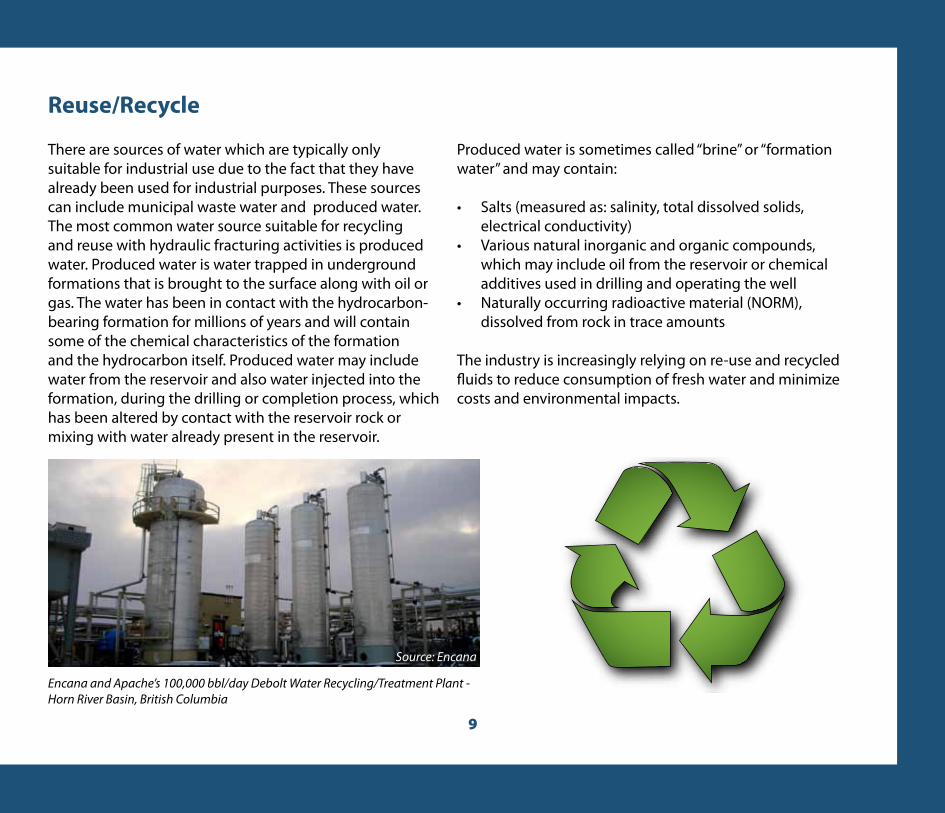
Encana and Apache’s 100,000 bbl/day Debolt Water Recycling/Treatment Plant - Horn River Basin, British Columbia
Source: Encana

10
What is the volume of water required to drill and complete a shale gas well?
Typically, drilling a conventional oil or gas well requires approximately 400 m3 of water. To complete wells in unconventional reservoirs, and in some conventional reservoirs, a process known as hydraulic fracturing is used to break the rock and create pathways for the oil or gas to travel to the wellbore. This process requires a significant volume of water to create enough of a fracture network to stimulate economic rates of production.
Completion activities in a typical unconventional gas well, because of the multiple fractures conducted, may require approximately 20,000 m3 of water. To put this in perspective, a golf course will use the same amount of water every 28 days. Approximately 20,000 m3 of water will grow nine acres of corn each year. While golf course and corn fields must be watered continually, unconventional gas wells are typically fractured only once.
20,000 m3 will grow 9 acres of corn each year
Golf courses use 20,000 m3 every 28 days

Water U
se
11
What quantities of water are required by the oil and gas industry?
In many cases, the collective volume of water used by the oil and gas industry is small relative to the overall availability of the local water resources and in comparison to volumes used by other users.
Water use will vary between different jurisdictions and within individual basins where unconventional hydrocarbon resources are being developed.
Impacts to surface water sources can be minimized by planning withdrawals during periods of high flow and storing water for future use, to accomodate seasonal or weather-related variability. To put the oil and gas industry’s consumption of surface water into perspective, the table below outlines typical flow volumes in major Canadian rivers.
Location River Annual Average
Newfoundland Gander River at Big Chute 119
Alberta Athabasca River at Hinton 175
Saskatchewan South Saskatchewan River at Saskatoon 254
Quebec Rivière aux Outardes à la Centrale de Chute-aux-Outardes 387
New Brunswick Saint John River below Mactaquac 809
British Columbia Fraser River at Hope 2 720
Ontario St. Lawrence River at Cornwall 7 350
Northwest Territories Mackenzie River at Norman Wells 8 480
Typical river flows at various locations in Canada(from lowest to highest daily average, m3/second)
Source: Environment Canada. This table is based on historical data to 1999, extracted from the national HYDAT database.

12
Water Conditioning
Produced water and flowback waterAny water that flows from a well as a result of oil and gas exploration or production activity is referred to as “produced water”. After a well has been stimulated to fracture the formation, some of the hydraulic injection fluid will flow back out of the well. This is a type of produced water, often called “flowback”. Drilling mud is not considered produced water.
Water conditioningDepending on the source of the water to be used for drilling and hydraulic fracturing activities, there may be different treatments or “conditioning” required before the water is suitable for oil and gas industry use. While it may be easiest to start with fresh water, which requires minimal treatment, most waters can be treated to condition them for drilling and completions use, as these operations are generally tolerant of modest salinity levels.
Produced water conditioningBefore produced water can be treated for hydraulic fracturing activities, the following steps must be taken to remove residual oil, suspended solids, dissolved organics, iron, some
salts and other impurities which may be present:
Stage 1: Produced water is processed through pumps and pipes which measure flow rate, pH and salinity. The produced water also passes through large horizontal tanks, air bubbling equipment, and specially designed skimmers which collect and separate any residual oil which may have been produced with the water.
Stage 2: Water from Stage 1 is pumped into a large tub containing several large tubes and plates that are connected to a direct electrical current. When the water travels between these plates and tubes, most of the dissolved solids are separated from the water.
Stage 3: Water from Stage 2 is transferred to a third tank where a small amount of flocculent agent, also used in municipal water treatment plants, is added to aid in the collection of fine particles that remain in the water.
Stage 4: In the final stage, water from Stage 3 is directed through plates where ozone is added to the stream to kill any bacteria. The remaining, extremely fine particles are removed using specially-designed filtration bags or by passing the water through sand-packed tanks. Chemical treatments can also be used at this stage.
In operations where flowback water is used for subsequent fracturing activites, usually minimal treatment is required, primarily to remove oil and suspended solids that may be present.
Source: MWH Global

13
Water Conditioning
Water and Sand 99.51%
Other 0.49%
Friction Reducer0.088%
Acid0.123%
Biocide0.001%
CorrosionInhibitor0.002%
Iron Control0.004%
Crosslinker0.007%
Breaker0.01%
pH Adjusting Agent
0.011%
Scale Inhibitor0.043%
GellingAgent
0.056%KCl 0.06%
Surfactant0.085%
Other0.49%
Conditioned Water Treatment Prior to Hydraulic FracturingIn order to optimize the effectiveness of hydraulic fracturing fluids, sometimes chemicals are added. Typically, 3 to 12 components are added depending on the characteristics of the source water and the type of formation to be fractured. These additives represent between 0.5 percent and 2 percent of the total fracturing fluid volume and are used to:
• reduce friction;• prevent micro-organism growth (also known as biofouling);• provide viscosity;• prevent corrosion of the casing (steel pipe) in the wellSand or other proppant is also added to the fluid to hold open the fractures created.
Chemicals & Public DisclosureDifferent jurisdictions mandate certain disclosure requirements for the oil and gas industry depending on local, provincial and federal regulations. Disclosure provisions help increase the public’s knowledge and access to information on chemicals, along with their uses and potential environmental impacts. Although the content of disclosure rules will differ throughout Canada, the intent of each is to provide the public with information about the chemicals being used to fracture wells.
Source: www.fracfocus.org

14
Water Disposal
The oil and gas industry has made great strides in the advancement of technologies which enable the recycling and reuse of waters used for drilling and completion activities. However, when water used in the oil and gas industry can no longer be recycled for practical reasons, it must be disposed of safely and responsibly, with minimal impact to humans and the environment. Disposal of this waste water is highly regulated and methods of water disposal allowed will vary from jurisdiction to jurisdiction.
Waste water from oil and gas development typically contains dissolved salts, hydrocarbons, trace metals and other elements. The most commonly approved disposal method is to inject waste water deep underground using a dedicated and specially constructed well. Deep well injection has been used in the Canadian oil and gas industry and throughout the world for decades to permanently isolate liquid waste from the environment.
A number of disposal methods are used by industry. The most common are discussed on the opposite page.
CCS Midstream’s West Edson Treatment, Recovery and Disposal facility. West Edson, Alberta
Source: CCS Midstream Services

15
Produced Water M
anagement
Option 1 – Deep Well InjectionThe drilling and licensing of a disposal well must comply with a number of government regulations which determine the need and feasibility of the well. A company must first apply and gain a license for the proposed disposal well. As part of that process, the well owner must demonstrate that the well and rock formation will accept the volume of proposed fluid and ensure that the contained fluids will remain isolated from any potential usable groundwater source.
Following approval and construction to rigorous standards, the well will be suitable for disposal purposes. Regular inspections and tests are required throughout the life of the well to prove mechanical integrity and fluid containment. Specific tolerances, such as pressure and disposal volumes, are monitored on a regular basis. Sealing and capping protocols are followed when the well’s capacity is reached. Even after abandonment, the well owner maintains liability for the well, ensuring any potential future issues relating to safety or the environment are handled in a responsible manner.
Option 2 – Privately Owned Treatment WorksWaste water from a production facility may also be delivered, with other drilling waste, to sophisticated waste handling facilities. These facilities treat the waste and, following treatment standards established by the facility operator and local regulators, dispose of the final waste water in designated disposal wells or make it available for reuse.
Option 3 – Land ApplicationThere are strict regulations which govern the application of produced water to the surface of the land. Land applications are generally appropriate for fluids which contain naturally biodegradable constituents (degradable organics or nutrients) and are also compatible with the soil chemistry. If the produced water is high in total dissolved solids (inorganics) it will require treatment before land application will be permissible.
Option 4 - Evaporation Ponds Evaporation ponds, not to be confused with tailings ponds associated with oil sands development, are used strictly as a measure to reduce waste water volumes and concentrate the waste for easier disposal – the waste must still be treated and/or disposed. The ponds themselves are secured with perimeter fencing to ensure that livestock do not access the fluids that have been discharged into the pond. This method of reducing waste water volumes is typically used in hot, arid regions.
Option 5 - Surface Water Discharge Surface Water Discharge permits may be issued for any point source that is discharging wastewater to surface waters. If permits are granted, there are effluent limits that will protect the beneficial uses of surface waters. The permits also contain sampling and reporting requirements that each facility must follow. Stream quality or designated use may also dictate discharge requirements.

16
Water Protection
Lease ConstructionThe oil and gas industry protects surface water through lease design and operations including storage on site. Regulations exist that manage the separation between the location of a surface lease and standing bodies of water. Design specifications and regulations which protect surface water are the same rules which apply to the conventional oil and gas industry and have been in place for many years. These regulations are mature and complete in experienced jurisdictions and regulators monitor existing regulations to ensure that they reflect evolving industry practices, such as high-volume water access. Other jurisdictions, with less oil and gas experience, will require time and training to develop an appropriate regulatory framework but can learn much from regulators working in a mature oil and gas environment.
Within the various provincial jurisdictions, there are strict regulations which control design and construction standards for oil and gas surface leases and regulate their proximity to surface water. Leases are often enclosed with berms which separate areas of conflicting use and direct water runoff (precipitation). Levels of stored fluids are tracked during wellsite operations to ensure potential fluid losses are quickly identified. If fluid loss occurs, containment measures put in place during construction ensure fluid leaks are confined and remediation can occur as soon as possible.
Prior to lease construction, companies and regulators carefully review existing soil and drainage conditions at the proposed lease site to ensure that the design, site preparation and construction reduces the potential for accidental spills to migrate onto adjacent land or into the subsurface.
Lease sites are also contoured so that all water from the lease (mainly rain water) collects in one corner. When there is a need to discharge surplus water, such as following particularly heavy rainfall, operators must comply with the local/regional/provincial discharge criteria to protect surface water. These criteria include pH levels, chlorides, hydrocarbons and total suspended solids. As with site selection, the regulatory requirements around release of water from the lease vary from one jurisdiction to another. Discharge
on private land will proceed only with landowner and other necessary approvals.
In addition to contouring the lease using appropriate material, soil and erosion control measures are constructed where water will be released from the lease. These can include mulch, erosion control blankets and diversion ditches. The goal is to control sedimentation and erosion off location.
Data MonitoringVan Frac Pumps Wellhead Frac Blender
Chemical StorageTrucks
Sand StorageUnits
Frac Tanks - StimulationFluid Storage
Adapted from Chesapeake Energy
Berm

17
Water Protection
Groundwater ProtectionShallow aquifer horizons containing fresh water in variable quality and quantities, and at various depths below the surface are present in many locations. With any oil and gas drilling operation, these aquifers are penetrated while drilling the wellbore deeper towards the production zones of interest. Recognizing the possibility of communicating with the shallow aquifers, a number of steps are taken by the oil and gas industry to ensure that aquifer layers are protected from contamination.
These steps include:• groundwater identification/characterization;• well construction procedures (drilling/completion); and• full life cycle well integrity monitoring
All steps are highly regulated by government agencies. Before drilling is permitted, the well owner must demonstrate a plan to comply with regulations.
Identification and Characterization of Groundwater SourcesIdentifying the depths at which groundwater exists is critical to ensure protection of this resource. From past experience, we know that fresh water aquifers are typically found at depths up to ~500m. These fresh water sources are generally separated from the productive oil or gas zones by several hundred meters or more of impermeable rock.
Geophysical logging can be used to collect data about what lies below the surface. These logs consist of a set of different downhole measurements which, when combined, give a picture
of the subsurface – sometimes including information on depth of freshwater. Where information is available from nearby oil and gas wells, it can be used to complement available data from water wells in the vicinity.
In certain circumstances, regional baseline groundwater testing and testing of water wells in close proximity to oil and gas wells, prior to development, is warranted and mandated by the regulator. Where possible and appropriate, the oil and gas industry and governments collaborate to understand groundwater resources.
Water Table
Uncon�ned aquifer
Con�ning bed
Con�ning bed
Con�ned aquifer
Recharge area for con�ned aquifer
Unsaturated zone
Artesian well
Water table well
Flowing artesian well
Potentiometric surface
the surface to which the water from a given aquifer will rise under
its full head
Source: www.waterencyclopedia.com

18
Well Construction With the location of the groundwater identified, well construction activities are engineered to ensure that groundwater-bearing horizons are isolated from the wellbore, thus eliminating the potential for contamination during subsequent drilling, completion and production operations. Some important steps in wellbore construction that help protect our groundwater include the setting of multiple steel casing strings of different sizes and the cementing of these casing strings into place.
There are typically at least three stages involved with the setting of casing.
1. Setting and cementing of conductor pipe near surface*2. Setting and cementing of surface casing (at a depth from surface
to below the base of fresh groundwater and sometimes at a depth much deeper)
3. Setting and cementing of the production casing to the total depth of the well. In some places an intermediate casing is also used and cemented in place to isolate any saline water or hydrocarbon zones which may be penetrated by drilling above the target horizon/reservoir.
It is important to recognize that the oil and gas industry uses technologically advanced cement to construct the wellbore. Concrete used for sidewalks is very different than that which is used to cement surface, production and sometimes intermediate casing in place. * Conductor pipe not shown in this diagram and not
used with the construction of all wells.
Source: Encana

19
Once these steps are complete, the cement casings act as barriers which prevent the mixing of fluids from within the wellbore and the groundwater the well has passed through. To ensure the integrity of the wellbore, the oil and gas industry uses diagnostic tools such as cement bond logs which provide assurance that the cement has isolated the wellbore from potential groundwater sources.
Prior to stimulation operations, the entire system is pressure tested to ensure well bore integrity. During fracturing operations, pressures within the wellbore are monitored to ensure that, in the event of any significant pressure change, which could indicate loss of wellbore integrity, operations can be suspended immediately.
Life cycle well integrityIt is important to ensure that groundwater is protected, not only in the first few stages of wellbore construction, but throughout the full life cycle of the well – from production through to abandonment. This is a regulated process whereby the owner of the well is required to ensure that there is no degradation of wellbore integrity over time. Possible well integrity conditions concerns could arise as a result of a poor cement bond, casing shift, corrosion of casing over time, etc. There are several diagnostic tools utilized by the oil and gas industry to help promote wellbore integrity (cathodic protection, chemical treatment, production packers, etc.) and several tools to identify wellbore integrity issues after they’ve occurred (corrosion logs, cement bond logs, production logs, etc).
In some horizontal wells, the horizontal portion of the well within the reservoir (often referred to as the lateral or leg) is completed open-hole without any cement surrounding the production casing. In these cases, intermediate casing is cemented to prevent migration of hydrocarbons or other fluids into the vertical section of the wellbore.
SURFACE CASING (24.5 cm)
INTERMEDIATE CASING (17.8 cm)
PRODUCTION CASING (11.4 cm)
Strict government regulations and industry practices protect fresh water aquifers while drilling the vertical section of a horizontal well.In this example, three sets of steel casing are cemented into place to prevent any fluid used in the drilling and fracturing process, or during production of natural gas, from contacting these aquifers.
Adapted from Questerre Energy Corporation

20
Provincial and federal regulations govern the oil and gas industry and have been in place for many years. They have been established to ensure that both the public and the environment are protected throughout exploration, development and production of conventional and unconventional hydrocarbon resources. Regulations, like the industry they monitor, are ever evolving in response to advancements in industry technologies and the techniques employed to extract the resource.
The fundamental regulatory basics of surface and groundwater protection, wellbore integrity and lease construction, for example, apply to all types of hydrocarbon developments; including unconventional resources. Similarly, the use of water for drilling and completion activities, such as hydraulic fracturing, requires approvals or permits from the appropriate authorities.
Proper regulations ensure that the environment and public are protected and that industry can continue to provide energy security and a cleaner, affordable source of energy.
Regulatory Considerations

21
Regulatory Considerations
Corporate Responsibility and SustainabilityNot only is industry governed by enforced regulations, there is also a degree of internal governance related to development.
Corporate social responsibility (CSR) is a form of corporate self-regulation which can be integrated into a business model. CSR policy functions as a built-in, self-regulating mechanism whereby businesses monitor and ensure active compliance within the spirit of the law as well as defined ethical standards. Typically, the goal of CSR is to embrace responsibility for the company’s actions and encourage a positive impact through its activities on the environment, consumers, employees, communities, stakeholders and other members of the public.
Environmental protection is also a part of a corporate values system. Industry has the ability and obligation to conduct operations in an environmentally and socially responsible and safe manner. Stewardship of a common environmental resource, such as water, is the responsibility of all users and can benefit all users. To this end, industry continues to achieve reductions in its water footprint through the development and application of technology. This approach makes economic sense from both a business and social responsibility perspective.
Recently in Canada, a set of guiding principles for hydraulic fracturing have been developed. Responsible operations include practices which safeguard the quality and quantity of regional surface and groundwater resources though sound wellbore construction practices, sourcing fresh water alternatives where appropriate and recycling water for reuse as much as practical. For more information about these guiding principles, please visit www.capp.ca.

22
Additive: Any substance or combination of substances comprised of chemical ingredients found in a hydraulic fracturing fluid, including a proppant, which is added to a base fluid in the context of a hydraulic fracturing treatment.
Annulus: The space between two concentric objects, such as between the wellbore and casing or between casing and tubing, where fluid can flow.
Aquiclude: An impermeable body of rock that acts as a barrier to the flow of groundwater.
Aquifer: The sub-surface layer of rock or unconsolidated material that allows water to flow within it. Aquifers can act as sources of groundwater, both fresh water and salt water.
Base fluid: The base fluid type, such as water or nitrogen foam, used in a particular hydraulic fracturing treatment. Water includes fresh water, brackish or saline water, recycled water or produced water.
Berm: A secondary containment system, typically constructed using soil, used to protect the land, soil and water surrounding the lease site in the event of a leak. Berms are also used as a method for draining excess precipitation from the lease site.
Carbon footprint: A carbon footprint is the total set of greenhouse gas (GHG) emissions caused by an organization, individual, event or product. Casing: Steel pipe placed in a well and cemented in place to isolate water, gas and oil from other formations and maintain hole stability.
Flowback: The flow of fracture fluid back to the wellbore after the treatment is completed.
Fracturing fluid: The fluid used to perform a particular hydraulic fracturing treatment and includes the applicable base fluid and all additives.
Greenhouse gas (GHG): Certain gases, such as nitrous oxide, carbon dioxide, and methane, that more effectively trap heat affecting the Earth’s surface temperature.
Horizontal drilling: A drilling procedure in which the wellbore is drilled vertically to a kick-off depth above the target formation and then angled through a wide 90 degree arc such that the producing portion of the well extends horizontally through the target formation.
Glossary and Terminology

23
Glossary and Term
inology
Hydraulic fracturing (aka ‘Fracking’): A method of improving the productivity of a reservoir by pumping fluids such as water, carbon dioxide, nitrogen or propane containing proppant (typically sand) into the reservoir at a sufficient pressure to crack or fracture the rock. The opening of natural fractures or the creation of artificial fractures provides pathways by which the oil or gas can flow to the wellbore.
Lateral: Situated on, directed toward or coming from the side.
Multi-stage fracturing: The process of undertaking multiple fracture stimulations in the reservoir section where parts of the reservoir are isolated and fractured separately.
Permeability: The ability of the rock to pass fluids or oil through it. The higher the permeability number, the greater the amount of fluid or oil that can flow through the rock. Permeability is measured in a unit called Darcy. Conventional reservoirs may have permeabilities in the 10’s to 100’s of milliDarcys or occasionally Darcy range. Unconventional or tight reservoirs usually have permeabilities in the micro to nano Darcy range (one millionth of a milliDarcy).
Porosity: The free space within the fine grained rock that can store hydrocarbons.
Produced water: Any water that flows from a well as a result of oil and gas exploration or production activity.
Propping agents/proppants: Non-compressible material, usually sand, ceramic beads or titanium oxides that are added to the fracture fluid and pumped into the open fractures to prop them open once the fracturing pressures are removed.
Reservoir: The rock that contains potentially economic amounts of hydrocarbons.
Reclamation: The act of restoring something to a state suitable for use.
Stimulation: Any of several processes used to enhance reservoir permeability close to the reservoir.

Canadian Society for Unconventional Resources (CSUR)Suite 420, 237 - 8th Avenue SECalgary, AB T2G 5C3
Phone: 403-233-9298; Fax: 403-233-9367Email: [email protected]; Web: www.csur.com