understanding the top server controllogix ethernet...
TRANSCRIPT
Understanding the TOP Server ControlLogix Ethernet
Driver
Page 2 of 23
Table of Contents
INTRODUCTION 3
UPDATE RATES AND TAG REQUESTS 4
CHANNEL AND DEVICE CONFIGURATION 7
PROTOCOL OPTIONS 9
TAG GENERATION 12
PERFORMANCE TUNING 16
THE DIFFERENCE BETWEEN READS AND WRITES 20
SUMMARY 23
Page 3 of 23
Introduction
The purpose of this paper is to give the user of the TOP Server ControlLogix Ethernet Driver some general
understanding of how it functions at a server and protocol level. The intent of this paper is to be read as
early in the system development process as possible, ideally before the programming of the ControlLogix
PLC. This is intended to aid the user in making the most effective configuration choices for their particular
system. This is a companion paper to “Optimizing I/O Server to AB ControlLogix Communications”
Overview
Since the original white paper “Optimizing I/O Server to AB ControlLogix Communications” was
written there have been a large number of enhancements to the TOP Server and the ControlLogix driver.
These enhancements have increased the potential ways of optimizing your communications to the
ControlLogix and removed some of the concerns noted in the original white paper in some cases. Other
users will find that rigorously following the guidelines in the original white paper will still be the best
method of communications for their system. The topics covered in this paper are intended to help the
user to understand the different parts of the server and driver that are most important to be aware of when
using the ControlLogix driver, so that they can make the most informed choice of systems configuration.
Topics:
Update Rates and Tag Requests
Channel and Device Configuration
Protocol Options
Tag Generation
The Difference Between Reads and Writes
Using Arrays
Timeout Settings
Page 4 of 23
Update Rates and Tag Requests
The first major question you have to answer when optimizing your system performance is how much data
do you need and how fast do you need it. If you have 1000 tags or less and need 1-second update rates
and choose to use the Symbolic protocol (see section on Protocol Options) you may not have to be
concerned about tag name length or location in many cases. The same is now also true if you need 5000
tags at 1-second update rates and can choose Physical Non-Blocking protocol. If you keep your tag
names short and use arrays at the global/controller tag level exclusively you can get this update rate for
25000 tags in Symbolic mode with a CPU time-slice of 55%. This assumes you don’t have any additional
network traffic or communications that would impact communications speed and your PC is fast enough to
handle the information it’s processing. If you don’t know the amount of data you need and the rate you
need it at, you won’t know when to make these choices and may very well end up reworking the whole
project or failing to meet the requirements.
Ideally data collection would be structured so that only a small group of tags would need to be collected
at any one time or continuously. This allows the PLC to spend more of its’ time doing the work it was
designed for and minimizes the communication stress placed on it.
The actual rate at which the TOP Server will poll the PLC is based on the group update rate set by the
OPC client or the Scan rate set in the Server when using SuiteLink or DDE connection methods with the
TOP Server and Wonderware InTouch for example.
Update Rates Using OPC
When using an OPC client, your OPC client determines the group update rate, so the Scan rates in the
Alias map are not used. See your OPC client application for more details on how to set the group update
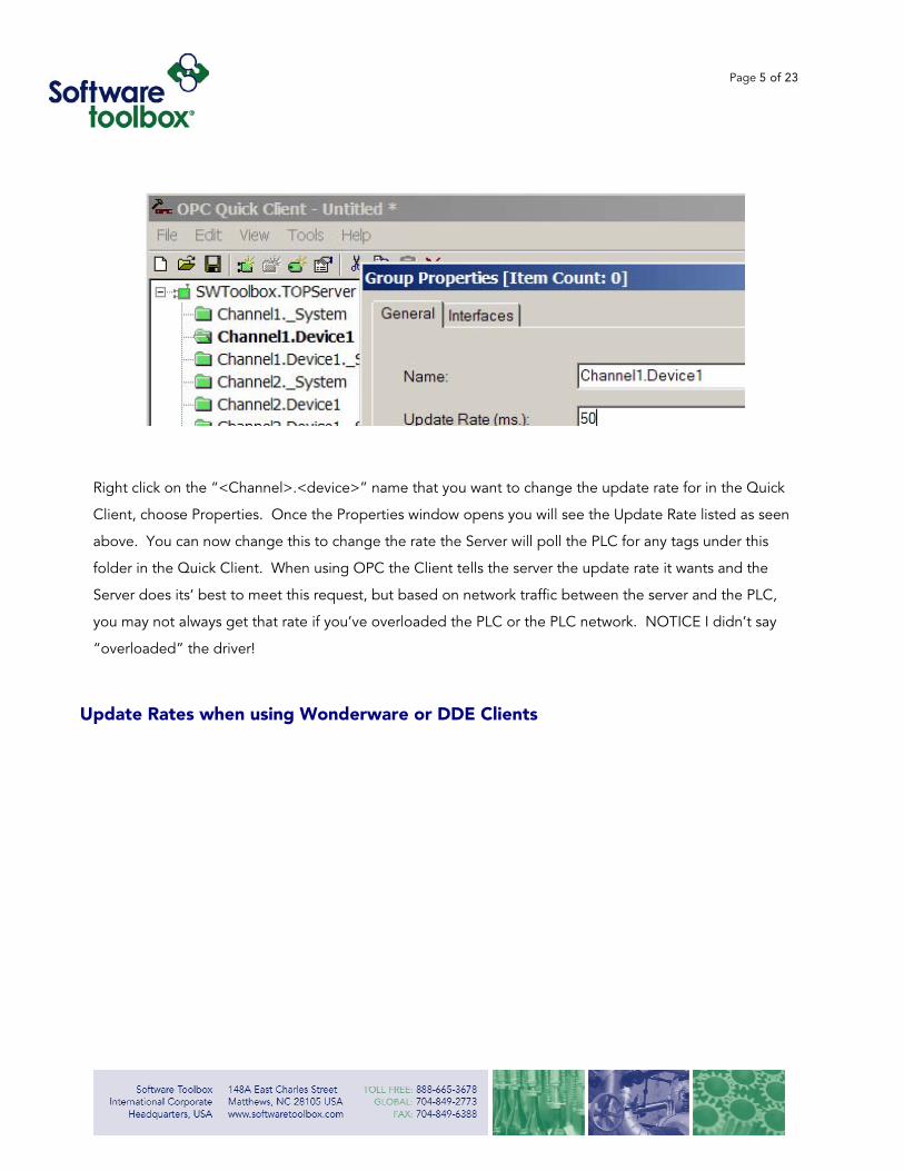
rate in your client. As an example, below we show how you set the group update rate when using our
OPC Quick Client connected to the TOP Server.
Page 5 of 23
Right c
Client,
above.
folder
Server
you ma
“overlo
Update
lick on the “<Channel>.<device>” name that you want to change the update rate for in the Quick
choose Properties. Once the Properties window opens you will see the Update Rate listed as seen
You can now change this to change the rate the Server will poll the PLC for any tags under this
in the Quick Client. When using OPC the Client tells the server the update rate it wants and the
does its’ best to meet this request, but based on network traffic between the server and the PLC,
y not always get that rate if you’ve overloaded the PLC or the PLC network. NOTICE I didn’t say
aded” the driver!
Rates when using Wonderware or DDE Clients

Page 6 of 23
When using TOP Server with Wonderware the Scan Rates for SuiteLink and DDE can be set for a Topic
und
You
per
the
rate
tag
If anT
a
We
you
to i
long
bui
tag
The
able
opt
er the Edit -> Alias Map:
can set a different scan rate for each Channel + Device combination, allowing you to tailor the
formance of the system to meet the data rate requirements of your project. The default of 0 results in
“Default Scan Rate” as defined in the TOP Server Options (default scan rate is 100ms). While the scan
s can be set for each tag it is recommended that they be set using the Alias Map as this overrides each
setting. These scan rate settings have no effect on OPC Scan rates.
you are using the SuiteLink or DDE connection methods from Wonderware d OPC connections from other clients at the same time, talking to the same OP Server, the scan rate requested by the OPC Client will affect the rate at which the server polls devices. If you want to keep the OPC client from ffecting the Server’s device-scan-rate it’s recommended you use the OPC
Time Monitor or LinkMaster as an update rate filter.
normally recommend setting the update rates to 100 or 200 ms faster then the goal update rate for
r Wonderware project. This addresses any latency between the TOP Server and the Client connected
t, or small fluctuations in communications. The server does not make a request queue, so if reads take
er than the request rate, then a buffer will not start to build. You cannot cause the TOP Server to
ld an infinite queue of requests. The result is that setting the server to 10ms for 5000 tags will return the
s as fast as possible, but no more memory will be used than if you set it to read at a rate of 1000ms.
update rate is also not a guarantee of how fast the server can return the information. If you are not
to get the number of tags you need at the rate you need them in the current configuration, then other
ions discussed in this paper will need to be considered.
Page 7 of 23
Channel and Device Configuration
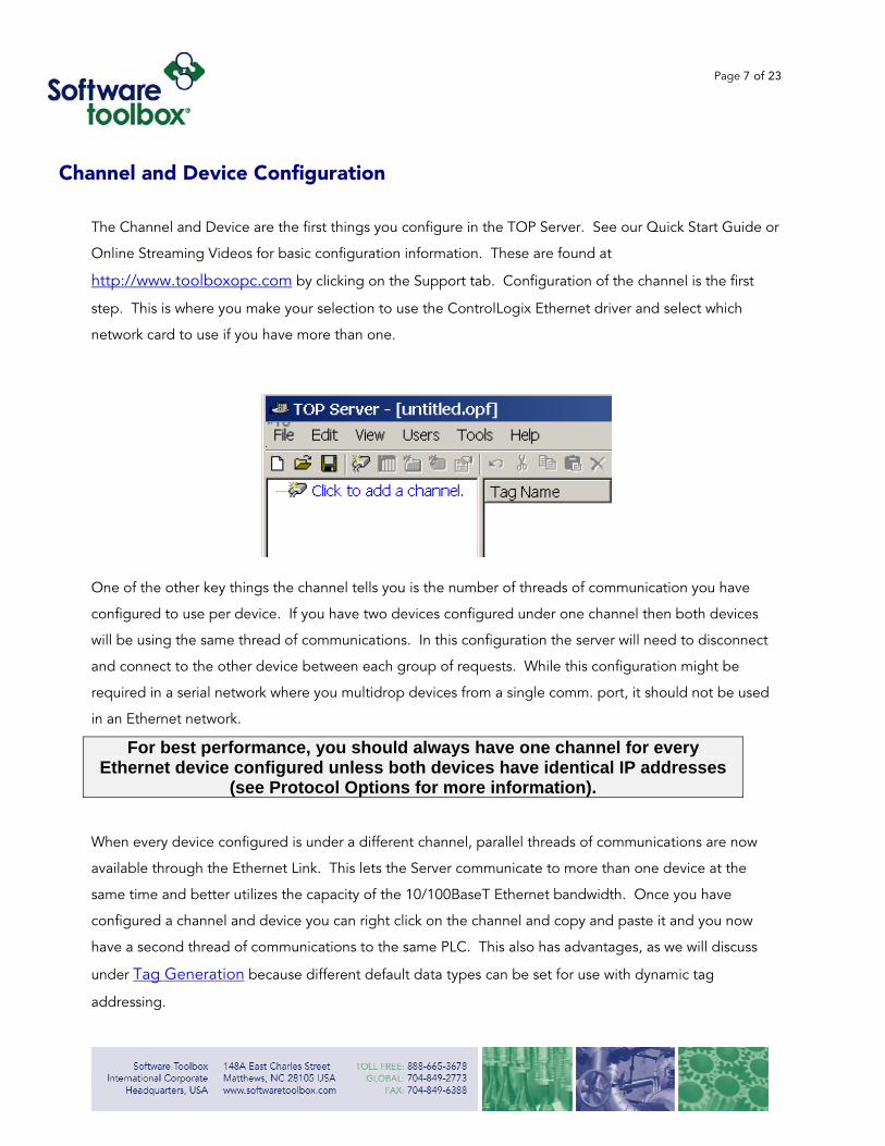
The Channel and Device are the first things you configure in the TOP Server. See our Quick Start Guide or
Online Streaming Videos for basic configuration information. These are found at
http://www.toolboxopc.com by clicking on the Support tab. Configuration of the channel is the first
step. This is where you make your selection to use the ControlLogix Ethernet driver and select which
network card to use if you have more than one.
One of the other key things the channel tells you is the number of threads of communication you have
configured to use per device. If you have two devices configured under one channel then both devices
will be using the same thread of communications. In this configuration the server will need to disconnect
and connect to the other device between each group of requests. While this configuration might be
required in a serial network where you multidrop devices from a single comm. port, it should not be used
in an Ethernet network.
For best performance, you should always have one channel for every Ethernet device configured unless both devices have identical IP addresses
(see Protocol Options for more information).
When every device configured is under a different channel, parallel threads of communications are now
available through the Ethernet Link. This lets the Server communicate to more than one device at the
same time and better utilizes the capacity of the 10/100BaseT Ethernet bandwidth. Once you have
configured a channel and device you can right click on the channel and copy and paste it and you now
have a second thread of communications to the same PLC. This also has advantages, as we will discuss
under Tag Generation because different default data types can be set for use with dynamic tag
addressing.
Page 8 of 23
The initial configuration of the TOP Server with the ControlLogix Ethernet Driver includes choosing a
protocol and tag generation option. As you better understand these different options you will be able to
make the channel and device configuration choices that are right for your system.
Page 9 of 23
Protocol Options
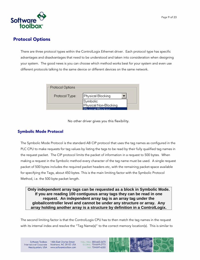
There are three protocol types within the ControlLogix Ethernet driver. Each protocol type has specific
advantages and disadvantages that need to be understood and taken into consideration when designing
your system. The good news is you can choose which method works best for your system and even use
different protocols talking to the same device or different devices on the same network.
No other driver gives you this flexibility.
Symbolic Mode Protocol
The Symbolic Mode Protocol is the standard AB CIP protocol that uses the tag names as configured in the
PLC CPU to make requests for tag values by listing the tags to be read by their fully qualified tag names in
the request packet. The CIP protocol limits the packet of information in a request to 500 bytes. When
making a request in the Symbolic method every character of the tag name must be used. A single request
packet of 500 bytes includes the required packet headers etc, with the remaining packet-space available
for specifying the Tags, about 450 bytes. This is the main limiting factor with the Symbolic Protocol
Method, i.e. the 500 byte packet length.
Only independent array tags can be requested as a block in Symbolic Mode.
If you are reading 100 contiguous array tags they can be read in one request. An independent array tag is an array tag under the
global/controller level and cannot be under any structure or array. Any array holding another array is a structure by definition in a ControlLogix.
The second limiting factor is that the ControlLogix CPU has to then match the tag names in the request
with its internal index and resolve the “Tag Name(s)” to the correct memory location(s). This is similar to

Page 10 of 23
accessing files on your hard drive. This requires the ControlLogix CPU Time-Slice to be set higher so that
the ControlLogix CPU can respond to the request between scan-cycles.
Physical Mode Protocol Overview
Physical mode protocols are unique to the TOP Server ControlLogix Ethernet Driver. Physical mode
protocols address the actual memory location in the PLC where a tag is stored and not the tag name itself.
This increases the rate of communications because requests are no longer limited by the 500 byte
character limit of the Symbolic Mode, nor the need for the PLC CPU to resolve the tag name to the
memory location. Why? Because we are requesting “memory addresses” instead of Tags! This helps
reduce the need for as high a PLC CPU Time Slice for the same data return rates.
In order to determine the actual physical addresses of the symbolic tag names, the driver must map the
whole tag-name index against the ControlLogix memory map during its initial connection. This mapping
increases the initial startup time of the TOP Server but can yield significant performance increases for
subsequent requests.
Systems that run 24/7 should be able to use the Physical type protocols with little issue. Systems that will
be stopping and starting frequently or choose not to accept a start-up delay will need to stay with
Symbolic type protocol and rigorously control the length of the PLC tag names and should make use of
arrays wherever possible. Large PLC projects create larger start-up times. This can cause a time-out to
occur in the TOP Server when trying to connect to the ControlLogix, which can be adjusted in the device
properties (see section following on Time-Out Settings).
RSLinx uses a method that is similar, but not the same as the Physical type protocols. The symbolic, tag-name-to-memory mapping is done by the PLC
CPU when using RSLinx. There are some issues inherent to this method that the ControlLogix Ethernet Driver in the TOP Server is able to avoid.
When the mapping is done by the PLC CPU additional CPU memory and resources are used to
communicate, so you don’t get as much of an advantage by lowering the overhead time-slice with RSLinx.
The more tags you have in your project the more free memory you need to have available in the
ControlLogix CPU to be able to communicate with RSLinx at all. Start-up times for larger projects are
longer for RSLinx using this method versus the Physical method. Given the same project of 5000 tags,
RSLinx method will run faster at a 55% CPU Overhead Time-Slice. At a CPU Overhead Time-Slice of 35%
Page 11 of 23
the TOP Server will run faster. Thus you can get better performance using less PLC Overhead Time-
Slice when using the TOP Server. Given that upgrading to faster PLC CPUs can be very expensive,
this makes the TOP Server an attractive option.
Physical Non-Blocking Mode Protocol
The Physical Non-Blocking protocol type uses the methods outlined above to communicate to the
ControlLogix. It’s unique in how it requests the memory addresses in relation to the Blocking method
discussed below. The Non-Blocking method makes requests of smaller chucks of memory addresses from
the PLC. The advantage of this is when your data is all under the global/controller level or is less than 50%
of a structure.
In our experience the majority of projects fall into the criteria described for
Physical Non-Blocking and should use this protocol type for the best performance.
Physical Blocking Mode Protocol
The Physical Blocking protocol type is the fastest way to read all the tags in the ControlLogix processor.
This method makes requests of the PLC based on whole structures of memory. This is an extremely
effective way of bringing large quantities of data back from the ControlLogix. If the data you need is less
then 50% of the structure on the other hand, this method is overkill and is actually slower than the Non-
Blocking method because of all the excess data transfer for un-needed data. If your project has some data
that is the majority of a structure and some that is only small parts of other structures you can break it up
under two identical devices (use the copy and paste function on the device). You can then then:
Set the device having its data as the majority of a structure to Physical Blocking, and
The other device to Physical Non-Blocking.
If you put the two devices under different channels you’ll get even better throughput. In summary: use the
flexibility of the driver (where applicable) to create multiple TOP Server devices that point to the same
ControlLogix, but use different Protocol types, i.e.
• Channel1.Device1 > could use Physical-Blocking mode
• Channel1.Device2 > could use Physical-Non-Blocking mode

Page 12 of 23
Tag Generation
There are five ways of getting tags into the TOP Server when using the ControlLogix Ethernet Driver.
• Dynamic Tag Addressing
• User Configured CSV Import
• User Interface Tag Entry
• L5K File Auto Generation
• PLC CPU Auto Generation
Definitions:
Dynamic Tags are PLC Addresses entered into the Client Application (i.e. OPC Client, InTouch etc.).
The TOP Server verifies the syntax of the Tag address and attempts to request the data from the PLC
based on the Clients request. The TOP Server will assume the tag is the default data type for the
address requested unless the “@datatype” suffix is added to the Tag address (see TOP Server help
files for details for valid data types).
Server Tags are useful names entered in the server that point to PLC Addresses and are stored in the
Server Tag database. Server Tags are not required when using Dynamic Tags, but both types can be
used in a project. Since Server Tags can be set to any valid data type for a particular PLC Address the
“@datatype” message is not required.
The first three methods are all user entry methods. The CSV Import is not the RSLinx CSV file, as this is not
supported in the TOP Server since we support direct L5K file import. The last two are methods of
automatically creating the tags in the Server. None of these methods should have any effect on the
communications performance and any method can be used with any protocol type discussed above.
There are some settings and inherent risks that can cause problems for different methods.
When using Dynamic tags you may have to add “@datatype” (for example
MyTag@Boolean) after the tag address. Use this when the Tag’s data type is not the same as the default data type in the TOP Server device properties.
Page 13 of 23
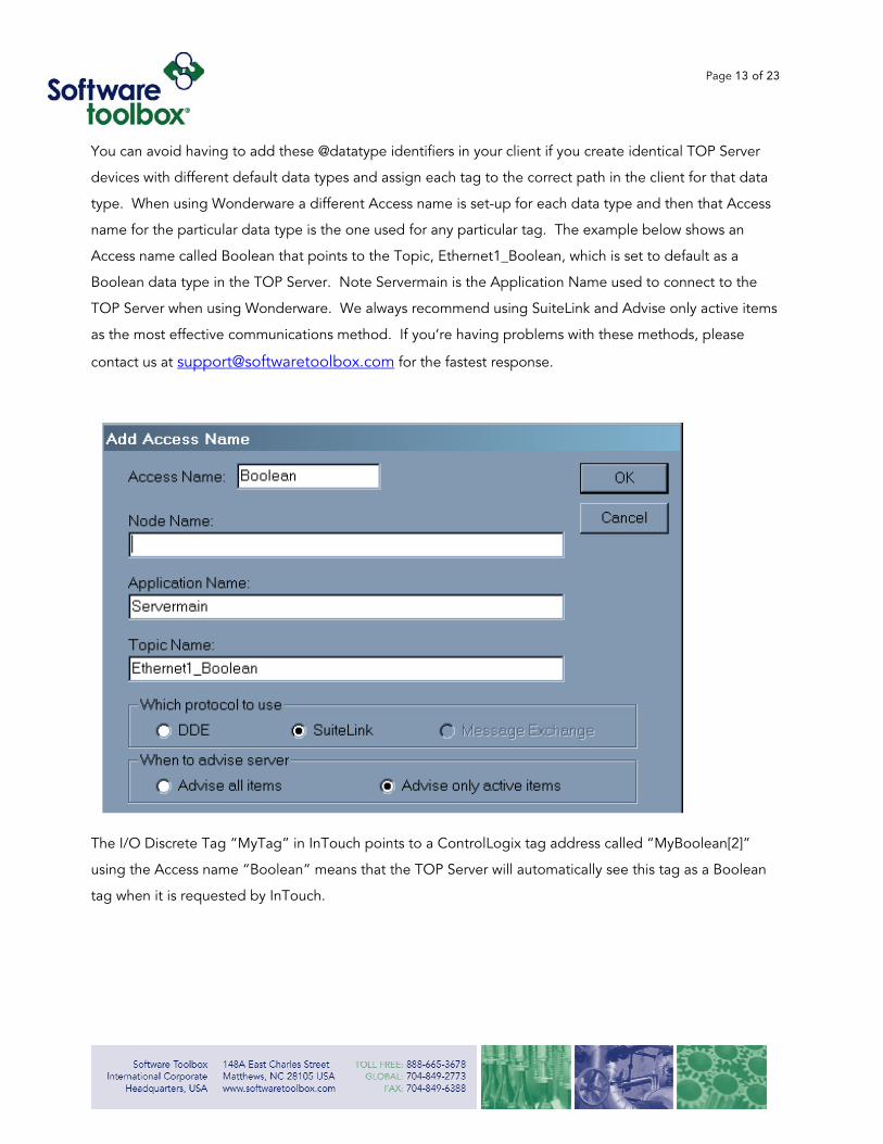
You can avoid having to add these @datatype identifiers in your client if you create identical TOP Server
devices with different default data types and assign each tag to the correct path in the client for that data
type. When using Wonderware a different Access name is set-up for each data type and then that Access
name for the particular data type is the one used for any particular tag. The example below shows an
Access name called Boolean that points to the Topic, Ethernet1_Boolean, which is set to default as a
Boolean data type in the TOP Server. Note Servermain is the Application Name used to connect to the
TOP Server when using Wonderware. We always recommend using SuiteLink and Advise only active items
as the most effective communications method. If you’re having problems with these methods, please
contact us at [email protected] for the fastest response.
T
u
t
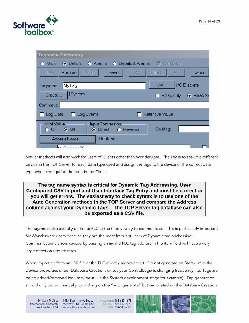
he I/O Discrete Tag “MyTag” in InTouch points to a ControlLogix tag address called “MyBoolean[2]”
sing the Access name “Boolean” means that the TOP Server will automatically see this tag as a Boolean
ag when it is requested by InTouch.
Page 14 of 23
Similar methods will also work for users of Clients other than Wonderware. The key is to set-up a different
device in the TOP Server for each data type used and assign the tags to the device of the correct data
type when configuring the path in the Client.
The tag name syntax is critical for Dynamic Tag Addressing, User
Configured CSV Import and User Interface Tag Entry and must be correct or you will get errors. The easiest way to check syntax is to use one of the Auto Generation methods in the TOP Server and compare the Address
column against your Dynamic Tags. The TOP Server tag database can also be exported as a CSV file.
The tag must also actually be in the PLC at the time you try to communicate. This is particularly important
for Wonderware users because they are the most frequent users of Dynamic tag addressing.
Communications errors caused by passing an invalid PLC tag address in the item field will have a very
large effect on update rates.
When importing from an L5K file or the PLC directly always select “Do not generate on Start-up” in the
Device properties under Database Creation, unless your ControlLogix is changing frequently, i.e. Tags are
being added/removed (you may be still in the System development stage for example). Tag generation
should only be run manually by clicking on the “auto generate” button located on the Database Creation

Page 15 of 23
tab under Device Properties. These features were nice ideas for being able to keep your tag database
always current with the PLC at start-up, but are not recommended for practical purposes unless you can
afford a very long start-up delay. These imports are not required for any of the protocols.
Page 16 of 23
Performance Tuning
Performance Tuning is the fastest and easiest way to take advantage of the configuration tips and suggestions noted in this paper and greatly
improves your project start-up time.
Even if you’re not going to use PLC CPU Tag Auto Generation to connect to your project tags, Auto
Generation can be a big help in overall TOP Server Configuration choices discussed in this paper. Once
you pull all your tags in to the TOP Server you can quickly delete the group(s) and tag(s) that you won’t be
using. A CSV Export and Import can also be done if you find editing the tag database easier this way.
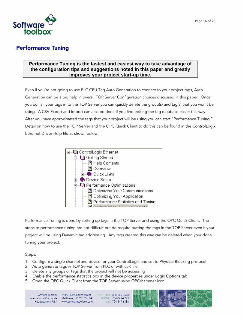
After you have approximated the tags that your project will be using you can start “Performance Tuning.”
Detail on how to use the TOP Server and the OPC Quick Client to do this can be found in the ControlLogix
Ethernet Driver Help file as shown below.
Performance Tuning is done by setting up tags in the TOP Server and using the OPC Quick Client. The
steps to performance tuning are not difficult but do require putting the tags in the TOP Server even if your
project will be using Dynamic tag addressing. Any tags created this way can be deleted when your done
tuning your project.
Steps:
1. Configure a single channel and device for your ControlLogix and set to Physical Blocking protocol 2. Auto generate tags in TOP Server from PLC or with L5K file 3. Delete any groups or tags that the project will not be accessing 4. Enable the performance statistics box in the device properties under Logix Options tab 5. Open the OPC Quick Client from the TOP Server using OPC/hammer icon

Page 17 of 23
6. Delete all folders in the Quick Client that don’t have PLC tags under them, for example all the folders ending with ._System or ._Statistics will not be used for this test.
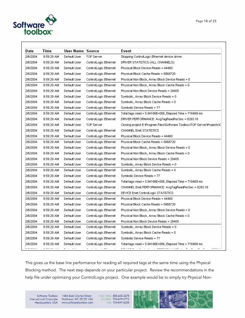
7. Right Click on the Connection Folder – SWToolbox.TOPServer and select disconnect 8. Go to the Tools menu and select Test Mode and check test 8 only 9. Set the time for about 5 minutes 10. Make sure Auto restart check box is not checked 11. Click OK 12. Right Click on the Connection Folder and select Connect 13. Go to the Tools menu and select Test Mode enable and click ok. 14. When the Event Viewer in the Quick Client says the test is stopped close the Quick Client. 15. Save the TOP Server Project 16. Close the TOP Server 17. Re-Start the TOP Server 18. Look in the TOP Server Event Viewer and Scroll up until you see the performance statistics. 19. Right click in the Event Viewer to print out the results as shown below.
Page 18 of 23
This gives us the base line performance for reading all required tags at the same time using the Physical
Blocking method. The next step depends on your particular project. Review the recommendations in the
help file under optimizing your ControlLogix project. One example would be to simply try Physical Non-
Page 19 of 23
Blocking Protocol next to see what difference this will provide for your tag configuration. There can also
be a great benefit in some projects by having two devices configured under one channel using different
protocols for different tag groups. Tags under the Global folder directly are best read using the Physical
Non-Blocking Protocol, but if you have the majority of a structure to read also it is best to read this in
Physical Blocking Protocol.
You may even configure some tags under a device reading Symbolic Protocol as quick start-up tags to populate the majority of a start-up
screen on your HMI while giving the Physical protocols time to map the memory address of the PLC.
Page 20 of 23
The Difference Between Reads and Writes
By its title, this may sound like a trivial topic, but when it comes to getting the most out of your
ControlLogix communications, it is a very important topic.
The various methods of optimizing reads have been discussed at length above. Writes are not optimized
in the same way. Writes take priority over reads from the default high of 10-1, the low being 1 - 1. Since
reads can be done in large blocks in single requests, many tags may actually get read for every 10 writes at
the default.
If you are having problems writing and believe you are only doing event
writes, open the diagnostic window in TOP Server under the Channel (right click the channel and choose diagnostics, if it’s not an option go to
properties – general tab, and enable the diagnostics). You will see Successful Read and Writes. If Successful Writes increases anytime you are not actually causing the event, then something else is writing to the
server. The server will not just do writes on it’s own!
• If everything is slow check your PLC CPU Overhead Time-Slice. • Also look for errors in the Server Event Log.
Normally leaving the Write Optimizations under the Channel at the default works fine when a project only
writes based on application events. For example someone presses a button or someone changes a set
point causing a tag to get written.
Issues can occur when the project is scripted to write values at a regular rate or large batches of values
have to be written. It’s best to avoid scripting that is writing the same value over and over. If it’s not
possible to do this, then select the option to write only the last value in the channel properties “Write
Optimization” tab. When large batches of information need to be written it is often better to use a
separate Channel and Device for a separate thread of communication as noted above.
Page 21 of 23
In situations where a Heartbeat tag is needed for communication timing checks it is best to use a read
from a counter or timer and avoid doing a write and read back. The write and read back method can often
cause a reduction in overall communications and increases network traffic. The TOP Server has a
“_System._Error” tag for each device configured that will read as a 1 if the communications have failed to
the device for any reason. Consider using this built-in tag in the TOP Server to monitor the status of PLC
communications.
Using Arrays
The TOP Server has the ability to read and write array tags in the ControlLogix PLC and present the data
as an array to the client application. Not all clients have the ability to read and write array tags, so your
ability to take advantage of this depends on the client you are using.
Writing can be done much more effectively with array tags because the
whole array can be written at one time to the PLC.
Arrays are also the fastest way to read tags in Symbolic protocol. The data transfer time between the
client and server software is also most efficient this way. Specific syntax for arrays is under the
ControlLogix Driver Help File – Address Formats.
Timeout Settings
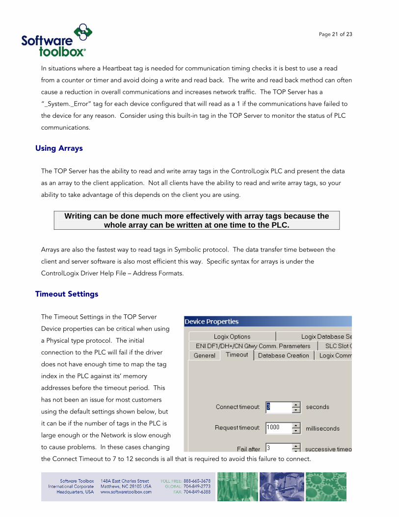
The Timeout Settings in the TOP Server
Device properties can be critical when using
a Physical type protocol. The initial
connection to the PLC will fail if the driver
does not have enough time to map the tag
index in the PLC against its’ memory
addresses before the timeout period. This
has not been an issue for most customers
using the default settings shown below, but
it can be if the number of tags in the PLC is
large enough or the Network is slow enough
to cause problems. In these cases changing
the Connect Timeout to 7 to 12 seconds is all that is required to avoid this failure to connect.
Page 22 of 23
Prior to TOP Server version 4.105.266 users would see behavior different than just failing to connect. The
driver would switch to Symbolic type protocol and attempt to connect, then once this was successful it
would then try Physical type protocol again and fail – this process would repeat continuously. This seemed
to be confusing to users. Now, you will just see it fail to connect using the Physical type protocol, but if
you switch to the Symbolic type it will connect to the ControlLogix and communicate. All clients must stop
connections to the TOP Server in order to change the type of Protocol used.
It’s also important to note the reason the timeout is occurring might be a network problem or the CPU Overhead Time-Slice might still be at the default of 10% instead of 30% to start with.
As stated above increasing the Connect timeout setting will allow the Physical Mode protocol time to
connect and overcome these errors.
Page 23 of 23
Summary
The TOP Server with the ControlLogix Ethernet Driver is a very powerful tool for ControlLogix
communications. Taking the time to understand the options available and the needs of your system will
help you to use it to best meet your needs.
• Know your Tag Requirements • Know your Update Requirements • Take Advantage of Different Channels for Different Devices • Understand the Strengths and Limitations of Each Protocol Mode • Try Performance Tuning with a larger project from the start • Minimize Writes when possible • Use Arrays when possible • Look for Errors in the Event log if communications are slow.
If you have any additional questions about the ControlLogix Driver or the TOP Server please send your
questions to [email protected] and we will respond as quickly as possible. We would also
welcome any feedback you have regarding this or any of our other papers.