understanding alloy design principles and · pdf fileindian journal of history of science,...
TRANSCRIPT

Indian Journal of History of Science, 45.1 (2010) 101-140
UNDERSTANDING ALLOY DESIGN PRINCIPLESAND CAST METAL TECHNOLOGY IN HOT
MOLDS FOR MEDIEVAL BENGAL
BARNALI MANDAL*, PRANAB K. CHATTOPADHYAY**,DIPTEN MISRA+ AND PRASANTA K. DATTA++
(Received 9 September 2009; revised 17 November 2009)
Two beautiful bronze images of medieval period unearthed inSouth Bengal have been investigated. After laser cleaning, materialcharacterization was undertaken to reconstruct the technology as well asthe knowledge base of metal workers. The bronze items were found to becast product whose chemistry belongs to copper – zinc – lead system withsmall addition of tin. The use of copper-zinc alloy in place of copper-tinwith addition of lead becomes quite significant in this respect and pointstowards developing a working knowledge for copper-alloy design. Theanalysis of microstructures signifies towards a casting technology, where,hot molds were used. For confirmation of the molds, some tribal metalcasting operations were also investigated. The technology was thenreconstructed in the laboratory and some casting as the facts were produced.Microstructures of all three types look almost similar leading to theconclusion that coppersmiths used hot clay molds for bronze production.
Key words: Alloy-design, Bronze casting, Hot molds, Lasercleaning
INTRODUCTION
East Indian subcontinent has got a long history of using differentmetals from ancient time and a number of archaeological sites have been* Research Scholar: Department of Metallurgical & Material Engineering, Jadavpur University,
Kolkata- 700 032. India, [email protected].** Centre for Archaeological Studies & Training, Eastern India, 4 Camac Street, Kolkata- 700
016. India, [email protected].+ Director: School of Laser Science & Engineering, Jadavpur University, Kolkata- 700 032.
India, [email protected].++ Professor: Department of Metallurgical & Material Engineering, Jadavpur University, Kolkata-
700 032. India, [email protected].
102 INDIAN JOURNAL OF HISTORY OF SCIENCE
excavated which produced a large number of metal images used by theancient population. From the days of Pa–n.d.u Ra–ja–r Dhibi1 to the recentexcavation of Tilpi in South Bengal it proves the occurrence of the metalartefacts in continuum.
Two copper- alloy images one of Ra–dha– and Kr. s. n.a (referred here asbronzes) were locally (Baruipur) collected by a Museum, Sundarban A– n‚chalikSan. grahasƒa–la–, Baruipur, South 24-Parganas, West Bengal, India, forconservation. Bronzes had been in heavily corroded state and neededrestoration for display at the museum gallery of Sundarban A– n‚ chalikSan.grahasƒa–la–. Both the metal images incidentally do not hold any stele behindthem. As per conventional museum practice, normal cleaning work wasattempted but failed to provide desired result. Jadavpur University wasrequested to help in the restoration work of these specimens.
For preservation, the bronze items were cleaned by application of aQ-switched Nd: YAG laser keeping the patina, as intact as possible, formaking them ready as exhibits. Small metal segments were made availableby the permission of the Museum authority for metallurgical investigationusing common metallurgical tools. The material investigation reveals thebronze items as cast product and the casting technology as well as alloydesign of the metals yielded valuable information about medieval metalforming technology of Bengal.
1. HISTORY AND CLEANING OF BRONZES
1.1. History of Metal Icons
Metal images of Kr. s. n.a (Fig.1) (Ht. 145 mm and Wt. 378 gm) andRa–dha– (Fig.2) (Ht. 150 mm and Wt. 716 gm) were recovered from the areaof Karergan.ga–, Rajpur Ba–za–r near Baruipur which falls on the Eastern sideof dried up A– digan.ga– (later down South became a part of Mani-river), alongwith archaeological debris of bricks, stone artefacts, Sƒivalin.ga, coins, etc.This South Western Sundarban area holds a number of importantarchaeological sites of Buddhist, Jain and Bra–hmanical origins at Boral2,Sitakunda – Atghora, Deulpota, Harinaryanpur, Nalgora, Kankandighi, JatarDeul, Baishhata and others. Close to Baruipur at Ramnagar many Bra–hmanicalimages of Mahis.a–surmardini–, Gan.esƒa–, Su–rya and at Baishhata Vis.n.umu–rtiimages are hallmark of a new style of bronzes for Bengal art3.

103UNDERSTANDING ALLOY DESIGN PRINCIPLES
Fig. 1. Icon Kr. s. n.a Fig. 2. Icon Ra–dha–
A prolific number of East Indian bronzes, were recovered fromdifferent sites of Bengal and Bangladesh, and some even were found inhoards. Mitra and Bhattarcharya4, Neogi and Schroeder, Sahai and ManowarJahan, Datta and Chattopadhyay, and others analyzed some of these images.A part of that booty, a large number of metal images were also unearthed in24-Parganas, in South Bengal in those areas mentioned in earlier paragraph.S. K. Saraswasti5 recorded a few of them which were found at Manir Tat (amariaci image) and Nalgora (an Ambika– image), near Baruipur. As recent as2006, new finds in 24-Parganas, of South Bengal were excavated byDirectorate of Archaeology, Government of West Bengal at a village Dhosa,near Jaynagar close to District headquarter Baruipur. Structural evidenceswere exposed at that site and there was suggestion of existence of stupaduring 1st and 2nd century BC. Close to that site lies Tilpi6 (22°15′ N, 88°38′N), in 24-Parganas, where bronze ingot, crucibles, hearth, slag were excavatedand that indicates continuous metal production and human habitation nearand adjacent regions of South Bengal, throughout historical periods - thoughravaged or washed away, by flood, or nor-wester and changing courses ofrivers. So is there, the recovery of metal images, on a regular basis in thisarea of 24-Parganas, from different periods of history, be it Gupta or Pa–la-

104 INDIAN JOURNAL OF HISTORY OF SCIENCE
Sena or Medieval or pre-modern ages. In close proximity, also inhabit alarge number of famous archaeological sites of Chandraketugarh, Balaidhap(near Mahasthan), Sƒa–gardi–ghi, etc.
The excavated materials proved to be remnants of a lost civil societyof this area. From the iconographic angle, Sri Hemen Majumdar, Secretaryof the Museum, suggested in consultation with many art historians, that theexcavated images represent icons of Ra–dha– and Kr. s. n.a, following Vais.navaitetradition of Madanapa–la (12th century) period.
Those two metal images are of very miniature form7. The imagesalso do not belong to the same pair, because Ra–dha– stands taller than Kr. s. n.a,which is most unlikely from the iconographic angle. Probably, the imageswere worshipped in separate enclosures, following Sƒaivate tradition ofPa–la-Sena period like Kevalacandrasƒekhara8 fashion. The probable reasonsof small sizes of icons may be explained as follows. South Bengal ran avibrant economy of trade and agriculture in historical periods and producedenough surpluses to indulge in costly metal culture. But, being deltaic andfragmented hinterland, the area (man. d.ala) never had a large politicalhegemony of a kingdom and was only capable of supporting little affluenceof producing tiny metal images for village temples as is. t.adevata–. So, Bengalbronzes, in comparison with South Indian bronzes predominantly are smallin size.
These bronzes from stylistic angle followed the proto-Australoidanatomy of round geometry as generally depicted by Jamini Roy’s folkwomen or Konarak’s dancers. As per physiognomy, Ra–dha– looks with wideopen eyes made by incision in the shape of angular ends (pat.alcera– cokh)with a plump face of Pa–la-Sena female icons. She possesses features of anideal Bengali woman, having short stature, voluptuous breast, and plumphip, supported by heavy buttocks, round hands and legs. Similar to HaraPa–rvati – bronze at Nalgora (7th - 8th century AD)9, a tr. ratha pedestal of afull blown lotus, a derivative of Pa–la-Sena period, carry the image. Shestretches out her palms probably to hold a lotus or a flower. Conversely,Kr. s. n.a has a chiseled frame, almost lifted from the figure of Cola bronze,with tr. bhan.ga pose, playing his flute. He wears a pointed crown over hishead and postures close to a nr. tya mu–rti (dancing pose), exposing gracefulradiance of romance, unlike soft Buddha image of Pa–la-Sena style. Hisexuberant mood was further enriched by a flat lotus at his knee with flying

105UNDERSTANDING ALLOY DESIGN PRINCIPLES
robes at his belt with a full-blown lotus pedestal under his feet, where petalsare projected outside at second layer of tri-ratha foundation. Kr. s. n. a imageagain was better crafted and fashioned with sleek physique having sunkeneyes, and can pose a challenge to earlier Pa–la-Sena bronzes in beauty. Allthese iconographic features, with a free-wheeling style of over-flowingemotions, after Buddhist period of Pa–la-Sena age, hold many sharp featuresof earlier bronzes acquired through generations.
Samatat area or Mani-river basin are dated between 8th - 12th centuryAD and many areas are variously dated from as early as Kus.a–n.a period(Kus.a–n.a coins at Jatardeul)10 to as late as 13th century AD. ConsideringBra–hmanical nature of icons, those two images could be placed between 13th
-14th century AD.
1.2. Laser Cleaning Operation of Bronzes
Both the bronzes before cleaning had hard dark corrosion coatingover the surface. The dark coating was removed by laser cleaning methodwith Q-switched Nd:YAG laser. Bronzes were not subjected to chemicalcleaning rather laser cleaning were adopted with a very slow removal rate,by Quanta System Laser (Model: PALLADIO, Serial No. PLLOOI-0207).During laser treatment bronzes got overheated which was countered by coolingthe items under water. It was also observed during Laser treatment, thatcleaning of the artefacts under wet condition yield better contaminant removalrate than dry condition. By repeated laser cleaning for two hrs per seatingit took 4 to 5 seating, for arriving at a dull but clear appearance. The dullappearance comes from the presence of a thin layer of patina. The patina isdeliberately left on the artefacts as it helps in protecting the substrate againstfurther degradation. Details are shown in Table - I. After removal of thecoating, Bronze castings showed dull yellow color with shallow irregularpoke marks over some areas.
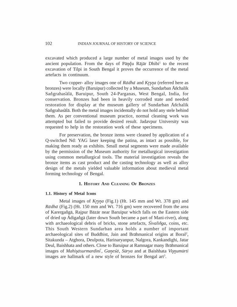
The cleaning sequence had been documented with photographs (Fig.3 and Fig. 4) after each stage for the items of Kr. s. n. a and Ra–dha–, respectively.
2. RESULTS OF THE LABORATORY ANALYSES
Two smaller inner fragments of the bronzes were collected and thenwere investigated using common metallurgical tools for Microstructure study,Scanning Electron Microscopy with EDX and X-Ray Diffraction Analyses.

106 INDIAN JOURNAL OF HISTORY OF SCIENCE
Table 1: Details of the Laser Cleaning Operation by Q-switched Nd: YAG Laser
Experimental Sample Time (Second) Frequency(Hz) Energy(m J)Run No.
1. Bronze* 30 10 155
2. Bronze 5 10 151
3. Bronze 60 10 157
4. Bronze 30 10 155
5. Bronze 60 10 156
6. Bronze 30 10 154
7. Bronze 30 10 152
8. Bronze 30 10 151
*Bronze here signifies copper-alloy items as is the convention of archaeologists and does notrepresent the scientific copper-tin alloy understood by metallurgists.
Fig. 3. Icon Kr. s. n. a Fig. 3(a) Half Cleaned Fig. 3(b). Totally Cleaned(as received)
107UNDERSTANDING ALLOY DESIGN PRINCIPLES
2.1. Chemical Compositions by SEM-EDX
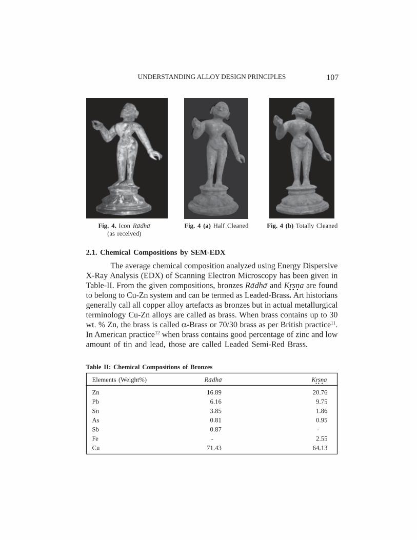
The average chemical composition analyzed using Energy DispersiveX-Ray Analysis (EDX) of Scanning Electron Microscopy has been given inTable-II. From the given compositions, bronzes Ra–dha– and Kr. s. n. a are foundto belong to Cu-Zn system and can be termed as Leaded-Brass. Art historiansgenerally call all copper alloy artefacts as bronzes but in actual metallurgicalterminology Cu-Zn alloys are called as brass. When brass contains up to 30wt. % Zn, the brass is called α-Brass or 70/30 brass as per British practice11.In American practice12 when brass contains good percentage of zinc and lowamount of tin and lead, those are called Leaded Semi-Red Brass.
Fig. 4. Icon Ra–dha– Fig. 4 (a) Half Cleaned Fig. 4 (b) Totally Cleaned(as received)
Table II: Chemical Compositions of Bronzes
Elements (Weight%) Ra–dha– Kr. s. n.a
Zn 16.89 20.76Pb 6.16 9.75Sn 3.85 1.86As 0.81 0.95Sb 0.87 -Fe - 2.55Cu 71.43 64.13

108 INDIAN JOURNAL OF HISTORY OF SCIENCE
Considering,
(i) Lead is soluble in copper at higher temperature having monotectic ααααα +L1,
(ii) But, lead is insoluble in copper at room temperature and get precipitatedbeyond the Cu-Zn system,
(iii) Although, lead forms eutectics with tin 13 at 183°C and so,
Lead becomes sparingly soluble in Cu-Zn-Sn system and let us assume,80 % of the lead, to be out of the alloy system. Therefore, 20% lead will besoluble in the Cu-Zn-Sn system.
For example, in icon Ra–dha–, percentage of Lead insoluble and outsidethe system: 6.16 x 0.8 = 4.93 wt.%, percentage of Lead: 6.16 x 0.2 = 1.23wt. % soluble in the system.
• Total elements remaining in the solid
Cu + Zn + Sn + As + Sb + Pb = 71.43 + 16.89 + 3.85 + 0.81 + 0.87+ 1.23 = 95.08 wt.%
• In weight percentage, the actual composition achieved by the alloy is,
Cu = 9508.043.71
= 75.13 %, Zn = 9508.089.16
= 17.76 %, Sn = 9508.085.3
= 4.04%,
As = 9508.081.0
= 0.85 %, Sb = 9508.087.0
= 0.92 %, Pb = 9508.023.1
= 1.29 %.
• With this alloy for calculation* of Zn-Equivalent14, the zinc will be,
17.76 (Zn) + 2 x 4.04 (Sn) + 1 x 0.85 (As) + 1 x 0.92 (Sb) + 1 x 1.29(Pb) = 28.9 %
• For Zn-Equivalent calculation the total comes to
28.9 + 75.13 (Cu) = 104.03
* The equivalents, due to Guillet,Element Sn Pb FeEquivalent Zn 2 1 0.9
109UNDERSTANDING ALLOY DESIGN PRINCIPLES
• Zn-Equivalent will be 03.1049.28
= 27.78 wt.% and Cu – will be 03.10413.75
=
72.29 wt.%.
Similarly, in icon Kr. s. n. a, percentage of lead insoluble and outside thesystem: 9.75 x 0.8 = 7.8 wt.%, percentage of lead: 9.75 x 0.2 = 1.95wt.% soluble in the system.
• Total elements remaining in the solid
Cu + Zn + Sn + As + Fe + Pb = 64.13 + 20.76 + 1.86 + 0.95 + 2.55+ 1.95 = 92.2 wt.%
• In weight percentage, the actual composition achieved by the alloy is,
Cu = 922.013.64
= 69.55 %, Zn = 922.076.20
= 22.52 %, Sn = 922.086.1
= 2.02 %,
As = 922.095.0
= 1.03 %, Fe = 922.055.2
= 2.76 %, Pb = 922.095.1
= 2.11 %.
• With this alloy for calculation* of Zn-Equivalent, the zinc will be,
22.52 (Zn) + 2 x 2.02 (Sn) + 1 x 1.03 (As) + 0.9 x 2.76 (Fe) + 1 x 2.11(Pb) = 32.18 %
• For Zn-Equivalent calculation the total comes to 32.18 + 69.55 (Cu) =101.73
• Zn-Equivalent will be 73.10118.32
= 31.63 wt.%. and Cu – will be 73.10155.69
=
68.37 wt.%.
Therefore, taking the composition as binary Cu-Zn system, the bronzeitems can be approximated as ααααα-brass from calculation of Zn-equivalent incopper as shown in Table - III. According to that convention, both Ra–dha–
and Kr. s. n. a icons can be termed as ααααα-brass, having constitutionally a singlephase structure, as shown in copper-zinc phase diagram.
Following American convention both can be termed as Leaded semi-red brass having small percentage of tin in both bronzes. Those can be

110 INDIAN JOURNAL OF HISTORY OF SCIENCE
Table III: Calculated Zn-Equivalent of Bronzes (wt.%) (excluding undissolved Lead)
Radha Kr. s. n.a
Zn Equivalent 27.78 wt.% 31.63 wt.%Cu 72.29 wt.% 68.37 wt.%(Pb) (+ 4.93 wt.%) (+ 7.8 wt.%)
further classified as Naval brass or a variety of Gunmetal where the basicalloy constituents are Copper-Zinc-Tin-Lead system, as per British practice.
Further to note that Bengal copper smiths introduced tin and leadinto low zinc brasses (zinc content, 17-20 wt.%). Metallurgically, the use ofCu-Zn system with large amount of lead and low amount of tin though is notvery conventional, but this complex combination of alloying elements aresomething notable for Bengal copper smiths. This may be due to non-availability of Tin in lower Bengal region or may be a borrowed practicefrom itinerant metal workers of copper hoard culture. Some of them stillexist as migratory Dokra–s at present. The similarity of metal culture betweenthe coppersmiths of Bengal and migratory Dokra–s is noteworthy.
On the basis of this discussion, it is well understood that Bengalmetal smiths probably had thoughtfully designed the alloy of bronzes.Therefore, the alloy designs of the two bronzes signify many notablemetallurgical understanding.
2.2. Microstructure of Bronze Icon Ra–dha–
2.2.1. Optical Microscopy
The microstructure of bronze (Fig.5) Ra–dha, in chemical composition,can be pronounced as a Leaded semi-red brass, Cu-Zn-Sn-Pb system, andshows typical cast brass structure with clear copper rich dendrites arrangedin fir-tree pattern (white areas) as ααααα-Cu phase. Black areas remain as last-to-freeze solute Zn-Sn rich βββββ-Cu phase. Black round spots, in betweendendrite, or sometime within dendrites indicate low melting point insolubleLead15, which does not dissolve in copper and present itself dispersed asuniformly distributed globules in the matrix and some time occupy the spacesof micro-voids or simply get entrapped. In such castings, lead effectively
111UNDERSTANDING ALLOY DESIGN PRINCIPLES
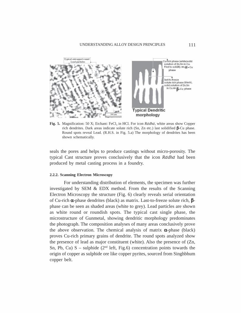
seals the pores and helps to produce castings without micro-porosity. Thetypical Cast structure proves conclusively that the icon Ra–dha– had beenproduced by metal casting process in a foundry.
2.2.2. Scanning Electron Microscopy
For understanding distribution of elements, the specimen was furtherinvestigated by SEM & EDX method. From the results of the ScanningElectron Microscopy the structure (Fig. 6) clearly reveals serial orientationof Cu-rich ααααα-phase dendrites (black) as matrix. Last-to-freeze solute rich, βββββ-phase can be seen as shaded areas (white to grey). Lead particles are shownas white round or roundish spots. The typical cast single phase, themicrostructure of Gunmetal, showing dendritic morphology predominatesthe photograph. The composition analyses of many areas conclusively provethe above observation. The chemical analysis of matrix ααααα-phase (black)proves Cu-rich primary grains of dendrite. The round spots analyzed showthe presence of lead as major constituent (white). Also the presence of (Zn,Sn, Pb, Cu) S – sulphide (2nd left, Fig.6) concentration points towards theorigin of copper as sulphide ore like copper pyrites, sourced from Singhbhumcopper belt.
Fig. 5. Magnification: 50 X; Etchant: FeCl3 in HCl. For icon Ra–dha–, white areas show Copperrich dendrites. Dark areas indicate solute rich (Sn, Zn etc.) last solidified βββββ-Cu phase.Round spots reveal Lead. (R.H.S. in Fig. 5.a) The morphology of dendrites has beenshown schematically.

112 INDIAN JOURNAL OF HISTORY OF SCIENCE
Fig. 6. Magnification: 100 X, Etchant: FeCl3 in HCl, all compositions are given above inwt.%. The microstructure is of same material as of Fig. 5, but the contrast is differentto indicate the matrix of ααααα-Cu phase. βββββ-Cu phase is white and round insoluble Pbparticles are of the same color. The minor phases obviously contain less volume fraction.Note the serial nature of dendrites at the left hand portion shown by parallel (Q%) lines,with sectional cut-off polygonal rounds at the right hand side (schematically later shownin Fig. 10). SEM-EDX analyses the material compositions of respective phases.
During non-equilibrium cooling16, segregation ratios k,
L
S
CC
k = …(1)
calculated by the minimum solute composition to the maximum solutecomposition, gives the idea of non-equilibrium cooling, during solidification.CS = Concentration of solute (Zinc) in solid phase, wt.% (First to solidify),CL = Concentration of solute in liquid phase, wt.% (Last-to-solidify) (seeFig. 7).
For icon Ra–dha–, Zn: 19.64 : 60.39 = 0.32, which is different form, equilibrium
diagram values of, ZnwtZnwt
CC
kL
S
.%20.%5.16
== = 0.83 obtained from Cu-Zn phase
diagram. [Taken @ 1000ºC, CS = 16.5wt.% Zn , CL = 20wt.%Zn].

113UNDERSTANDING ALLOY DESIGN PRINCIPLES
This indicates deviation from phase diagram compositions andoccurrence of the non-equilibrium cooling of liquid metal. In case of cellulardendrites Segregation ratios (k) generally change significantly18. The cellulardendrites and Segregation Ratio (CS:CL), also provide information aboutslow cooling rate of the casting where, as only low liquid temperature gradientcan exist at that condition.
From the classical solidification condition for plane frontsolidification19,
−≥RG
Dk
kmC )1(0 −…(2)
Where,G = Temperature gradient of cooling liquid metal, K/cm,R = Rate of solidification front advancement, cm/sec,m = Slope of the liquidus line in Cu-Zn Phase Diagram,
k = Partition coefficient of solute in solid and liquid phase = L
S
CC
,
C0 = Average composition of solute (Zinc) of the liquid metal,
D = Diffusivity of Zinc in Copper, during solidification.
Fig. 7. A part of Cu-Zn phase Diagram17

114 INDIAN JOURNAL OF HISTORY OF SCIENCE
In this case the values for Cu-Zn system of the liquidus line,
83.46.376.181
6.37)9026.1083(
−=−=−
−=m K/ wt. % Zinc,
8.083.020
5.16≈===
∗
L
S
CC
k , *from Cu-Zn phase diagram.
D = Diffusivity19 of zinc in copper @ 727 - 955°C, )(
00TRQ
eDD−
= …(3)
Substituting values of, @ 1000°C, D0 = 3.2 x 10⁻³ cm2/sec, Q = 18.5kcal / g. atom,
R0 = 1.98 cal /mole/K, T = (1000 + 273)K = 1273 K, D = 2.9735 x10⁻³ cm2/sec (calculated).
For icon Ra–dha–, Zn content, C0 = 16.89 wt.%
Therefore, Putting values, Dk
kmC )1(0 −− = 6858 K. sec/ cm2,
⇒ 6858≥RG
for plane front solidification.
Assume, for G = 10 K/cm, and G = 5 K/cm,
⇒ R = 1.46 x 10⁻³ cm/sec ⇒R = 7.29 x 10⁻⁴ cm/sec. For thin section in Fig. 8 of icon Ra–dha–, the rim thickness is 2 mm,
with 1 mm is the depth of solidification front from both ends for platecasting. The local solidification times come approximately, 1/R or 68 secand 137 sec, respectively.
This first solidification time is much less than expected in actualpractice of investment casting. So, the actual temperature gradient of coolingliquid metal is much lower and suggests the application of hot molds which
can only actuate low heat flux (transfer) rate dxdTkq 1= , with subsequent long
solidification time.

115UNDERSTANDING ALLOY DESIGN PRINCIPLES
Fig.8. Thin section of the icon Ra–dha–
2.2.3. X-Ray Diffraction (XRD) Analysis of Icon Ra–dha–
Analyzing the X- Ray diffraction data for icon Ra–dha– (Table IV) anumber of phases have been identified21. The important phases are locatedin Fig. 9. From the X-Ray Diffractogram, the presence of dominant ααααα-Cuphase (solid solution of Zn, Sn in Cu), FCC is confirmed. Some minor βββββ-phase (solid solution of Sn, Zn in Cu), BCC are also present. Insoluble Leadas separate phase can be found in the analyses.
Fig. 9. XRD Pattern of the Bronze sample of Icon Ra–dha–
116 INDIAN JOURNAL OF HISTORY OF SCIENCE
2.3. Microstructure of Bronze Icon Kr. s. n.a
2.3.1. Optical Microscopy
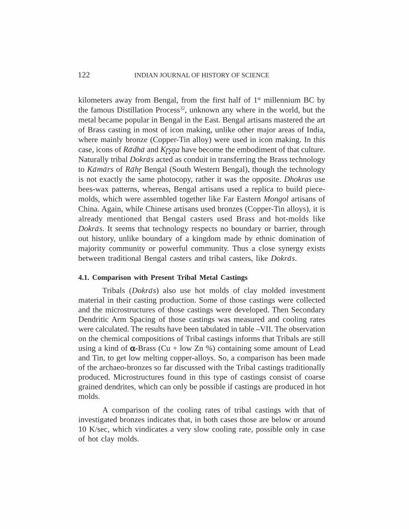
The optical micrograph (Fig. 10) shows equiaxed dendrites or cellulardendrites, with grey Lead particles all around. Dendrites are the signature ofcasting process and that vindicates the metal forming technology of BronzeKr. s. n. a as casting.
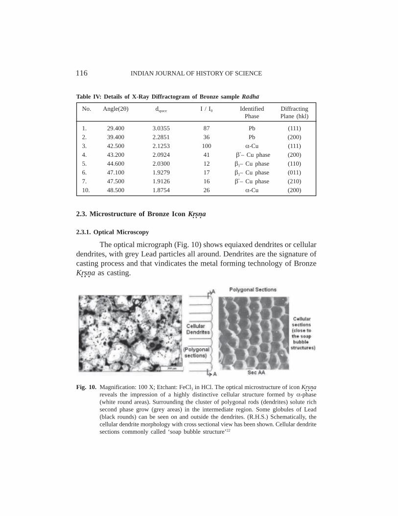
Table IV: Details of X-Ray Diffractogram of Bronze sample Ra–dha–
No. Angle(2θ) dspace I / I0 Identified DiffractingPhase Plane (hkl)
1. 29.400 3.0355 87 Pb (111)2. 39.400 2.2851 36 Pb (200)3. 42.500 2.1253 100 α-Cu (111)4. 43.200 2.0924 41 β”– Cu phase (200)5. 44.600 2.0300 12 β1– Cu phase (110)6. 47.100 1.9279 17 β1– Cu phase (011)7. 47.500 1.9126 16 β”– Cu phase (210)10. 48.500 1.8754 26 α-Cu (200)
Fig. 10. Magnification: 100 X; Etchant: FeCl3 in HCl. The optical microstructure of icon Kr. s. n.areveals the impression of a highly distinctive cellular structure formed by α-phase(white round areas). Surrounding the cluster of polygonal rods (dendrites) solute richsecond phase grow (grey areas) in the intermediate region. Some globules of Lead(black rounds) can be seen on and outside the dendrites. (R.H.S.) Schematically, thecellular dendrite morphology with cross sectional view has been shown. Cellular dendritesections commonly called ‘soap bubble structure’22

117UNDERSTANDING ALLOY DESIGN PRINCIPLES
The formation of distinctive cellular structure is significant, whichneeded a certain level of under cooling, obtained only in a slow solidificationprocess, like sand molding or investment molding.
2.3.2. Scanning Electron Microscopy
Under SEM the sample was further investigated and micro-analyzedby EDX method. The microstructure (Fig. 11) of Bronze Kr. s. n. a reveals coarsedendrites with lots and lots of Lead precipitated within or around dendrites.Coarseness of dendrites leads to the conclusion that the castings were produced
in hot molds. Due to the low temperature gradient ⎟⎠⎞
⎜⎝⎛
dxdT between cooling
liquid metal and hot (heated) mold, the heat transfer rate becomes very smalland solidification takes long time, when adequate diffusion of atoms allowgrowth (G) of dendrites or grains and the coarseness of dendrites develop.
With respect to bronze Ra–dha–, the amount of lead can be seensignificantly higher. The chemical compositions of ααααα-Cu and βββββ-Cu (blackareas) show (Fig.11) Cu-rich and solute rich elements respectively. Last-to-
Fig. 11. Magnification: 400 X; Etchant: FeCl3 in HCl, all compositions are given above inwt.% (Material same as Fig.10). The coarse microstructure of icon Kr. s. n.a has beendepicted in the SEM photograph. The structure is single phase of ααααα-Cu with very littleβββββ-phase (black colored) within it. Dendrites are very coarse indicating very slow rateof solidification. The round phases are insoluble Lead constituents. The compositionsof matrix ααααα-phase and minor βββββ-phase in the inter-dendritic region have been marked.

118 INDIAN JOURNAL OF HISTORY OF SCIENCE
freeze Lead constituent was also analyzed. The insoluble Lead effectivelyfills up pores between dendrites and makes the casting more sound. Duringnon-equilibrium cooling23, segregation ratios, calculated by the minimumsolute composition to the maximum solute composition, during solidificationas follows:
Zn: 17.51 : 23.70 = 0.74.
Under formation of cellular dendrites SR generally increasessignificantly, with respect to equilibrium partition ratio, k.
2.3.3. X-Ray Diffraction (XRD) Analysis of Icon Kr. s. n.a
In case of Kr. s. n. a all the comments about the bronze Ra–dha– are valid— that is the major phase is ααααα-Cu phase and minor phase is βββββ-Cu phasewhich are shown in Fig. 12 and Table - V. Only exception is the peak oflead24 which is substantially higher with respect to that of Ra–dha–, indicatinghigher amount of Lead is present in this sample.
Fig.12. XRD Pattern of the Bronze sample of Icon Kr. s. n.a

119UNDERSTANDING ALLOY DESIGN PRINCIPLES
3. TECHNOLOGY AND TYPE OF MOLDS USED FOR
PRODUCTION OF BRONZE IMAGES
Primary investigation so far discussed conclusively proves the metalforming technology of bronze icons follows metal casting route. To find outfurther the type of the casting process, let us consider the parameter ofSecondary Dendritic Arm Spacing, which can provide us the types of castingprocess used by the metal workers.
According to Beeley25, the Arm spacing of Secondary dendritesconfirms to the relation λ r a = B where, ‘a’ and ‘B’ are constant and λ =Secondary Dendritic Arm Spacing in µm, r = Cooling Rate in K/sec. Therelationship signifies refining effect due to increasing cooling rate, as theSecondary Dendritic Arm Spacing (SDAS) is inversely proportional to thecooling rate. Also this represents coarsening of dendrites due to decreasingthe cooling rate, i.e. the slower the cooling rate wider is the Dendritic ArmSpacing. In this particular case of hot molds, the cooling rate of the castingswould be slower and thereby, the Dendritic Arm Spacing would be larger.According to Hwang26, for Tin-Bronze, the Secondary Dendritic Arm Spacingfollows the relationship of
λ =101 x r - 0.42 …(4)
Using this relationship, the Dendritic Arm Spacing of both bronzes,Ra–dha– and Kr. s. n. a, have been measured from microstructures (ref. Figs. 5, 6,10, 11) and their cooling rates calculated using equation (4), have been givenin Table VI.
Table V: Details of X-Ray Diffractogram of Bronze sample, Kr. s. n.a
No. Angle(2θ) dspace I / I0 Identified Phase DiffractingPlane (hkl)
1. 29.500 3.0254 88 Pb (111)2. 36.000 2.4927 43 Pb (200)3. 39.500 2.2795 47 Undefined Undefined4. 42.500 2.1253 100 α-Cu (111)5. 43.200 2.0924 57 β”– Cu phase (200)6. 44.600 2.0300 44 β1– Cu phase (110)7. 47.200 1.9240 26 β1– Cu phase (011)8. 47.600 1.9088 24 β”– Cu phase (210)9. 48.600 1.8718 38 α-Cu (200)

120 INDIAN JOURNAL OF HISTORY OF SCIENCE
The cooling rates of both bronzes show very slow cooling rate duringsolidification. The question arises what type of molds produced this slowcooling rates.
Molds of the Archaeological period as quoted in the text27 refer toClay Molded process. The clay molds consist of clay, sand, charred Rice-husk and other cotton fabrics bound together to produce a highly non-conductive, ceramic material of poor heat conductance (k1) comparable tosilica sand (k1 = 6.0 w/m.K)28. On heated condition, the molds were dewaxedand the red hot molds were supposed to be used for copper-alloy castings asmentioned in the text. If hot molds are used, then conductive heat flux,through mold for removal of heat energy of solidification during phasetransformation would be less as the temperature gradient between copper-alloy and the hot mold would be very low and the ceramic heat conductance,k1 would be very poor. The poor heat transfer rate or the heat extraction ratethrough the mold will cause the solidification to take place for long time andthere will be ample time (t) and sufficient temperature (T), when diffusionof atoms could take place. Increased diffusion rate as well as high temperatureof the liquid metal would produce low nucleation rate29 (n) and comparativelyhigh growth rate, and ultimately coarse dendrites will result. Due to highlocal solidification time, Secondary Dendritic Arm Spacing will also bewider. Therefore, the slow cooling rate of the order of single digit coolingrate (K/sec.), confirms red-hot condition as well as ceramic clay molds usedduring casting.
Table VI: Secondary Dendritic Arm Spacing and Cooling Rates of Bronzes
Specimen Secondary Dendritic Cooling Rate (r),Arm Spacing (λ), µm K/sec.
Bronze Ra–dha– 59.50 3.52278.57 1.81866.66 2.68754.56 4.33347.62 5.990
Bronze Kr. s. n.a 60.00 3.45125.00 0.6080.00 1.7450.00 5.3370.00 2.39

121UNDERSTANDING ALLOY DESIGN PRINCIPLES
4. CONTEXT OF RELATIONSHIP OF THE TRADITIONAL
CASTINGS WITH DHOKRA CASTINGS
Eastern India, in particular Bengal region has been fortunate enoughto have various types of metal workers from pre-historic time, due to thepresence of abundant mines, thick forest and heterogeneous populations,expert in many trades. Over and above natural resources, there is a zigzagcorridor of continuous tribal path, down the lower Vindya region, from theextreme West coast of Dang district of Gujrat, through Nimar in Maharastra,Bastar, in Chhattisgarh, Hazaribagh- Ranchi, in Jharkhand up to the foothillsof Rajmahal hills in the West of Bankura. The forested area remainedunaffected almost in post-Harappa period, over two millennia from the bloodyupheavals of Gangetic civilization. Thereby a tremendous inter-mixing oftechnology took place from the pushes of Southern Dravidians, WesternMarathas or Gujratis or Eastern Mongols towards the wooded plains ofriverine East India. Thankfully medieval Bengal was privy to these histories.There is a record of eight types of metal workers (As. t.aka–ma–r)30 that originatedin Bengal- probably those were Svarn.aka–ma–r (Goldsmith), Ca–ndka–ma–r(Silversmith), Ta–mraka–ma–r (Coppersmith), Ka–nsaka–ma–r (Bronzesmith),Dokra–ka–ma–r (Tinsmith or Brazier or Lost-wax Caster), Pitulika–ma–r (Brasssmith), Lauhaka–ma–r (Ironsmith), and Ghat.aka–ma–r (Ghat. i» Ghat. = Pot =maker or Sand-clay casting smith or Impact loader or Sheet metal worker).There might be intra- or inter-caste rivalry or conflicts of smithy communitiesand interchanging of job work, still they shared their knowledgebase andcontributed heavily to the up-gradation of technology. In every trade this wastrue. Most of the Tamil or Austro-Dravidian dialects of indigenous tribes,which contributed generously to modern Bengali or Oriya, have got excellentglossary of technical terms and rules, which are used by workers even to-day, through out the East, be it casting, forging, carpentry or boat making.The ancestors of modern Dokra–s or some such tribes31 might be the originatorsof Copper-Hoard Cultures who carried their brilliant casting technology ofhot-molds and profound knowledge of strong Copper-Zinc alloys, known asBrass (Pit-tal = Yellow colored metal) to the East, in Bengal. Incidentally,Brasses are famous for low melting points and so were very easy for meltingor liquefaction during casting. The irony is that Zinc was being produced inthe Western India by people of Rajputana or Rajasthan, thousands of
122 INDIAN JOURNAL OF HISTORY OF SCIENCE
kilometers away from Bengal, from the first half of 1st millennium BC bythe famous Distillation Process32, unknown any where in the world, but themetal became popular in Bengal in the East. Bengal artisans mastered the artof Brass casting in most of icon making, unlike other major areas of India,where mainly bronze (Copper-Tin alloy) were used in icon making. In thiscase, icons of Ra–dha– and Kr. s. n. a have become the embodiment of that culture.Naturally tribal Dokra–s acted as conduit in transferring the Brass technologyto Ka–ma–rs of Ra–hr. Bengal (South Western Bengal), though the technologyis not exactly the same photocopy, rather it was the opposite. Dhokras usebees-wax patterns, whereas, Bengal artisans used a replica to build piece-molds, which were assembled together like Far Eastern Mongol artisans ofChina. Again, while Chinese artisans used bronzes (Copper-Tin alloys), it isalready mentioned that Bengal casters used Brass and hot-molds likeDokra–s. It seems that technology respects no boundary or barrier, throughout history, unlike boundary of a kingdom made by ethnic domination ofmajority community or powerful community. Thus a close synergy existsbetween traditional Bengal casters and tribal casters, like Dokra–s.
4.1. Comparison with Present Tribal Metal Castings
Tribals (Dokra–s) also use hot molds of clay molded investmentmaterial in their casting production. Some of those castings were collectedand the microstructures of those castings were developed. Then SecondaryDendritic Arm Spacing of those castings was measured and cooling rateswere calculated. The results have been tabulated in table –VII. The observationon the chemical compositions of Tribal castings informs that Tribals are stillusing a kind of ααααα-Brass (Cu + low Zn %) containing some amount of Leadand Tin, to get low melting copper-alloys. So, a comparison has been madeof the archaeo-bronzes so far discussed with the Tribal castings traditionallyproduced. Microstructures found in this type of castings consist of coarsegrained dendrites, which can only be possible if castings are produced in hotmolds.
A comparison of the cooling rates of tribal castings with that ofinvestigated bronzes indicates that, in both cases those are below or around10 K/sec, which vindicates a very slow cooling rate, possible only in caseof hot clay molds.

123UNDERSTANDING ALLOY DESIGN PRINCIPLES
Table VII: Details of sources, metallographic study and cooling rates of Tribal Castings
5. RECONSTRUCTION OF THE CASTING TECHNOLOGY IN LABORATORY
For further confirmation of metal technology, a reconstruction of themetal casting process was simulated in Rural Casting Laboratory of JadavpurUniversity. Some castings of brasses were produced in moderately hot claymolds as follows:
Stage 1: Core Making: A clay-core was made up of appropriate form, usinga mixture of alluvial, rice-husk and coarse silica sand (40-60 AFS No.) inthe ratio of 4: 1: 1, with sufficient moisture so as to develop enough flowabilitysuitable for making their form.

124 INDIAN JOURNAL OF HISTORY OF SCIENCE
Stage 2: Polishing, Drying and Wax Making: The top surface was polishedand the core was dried slowly. A wax recipe of 20:80 of Sal-dammer resin(dhuna): Bees wax was prepared.
Stage 3: Wax Pattern Making: Waxing was done over the dried core, alongwith suitable runners and gates, made of the same wax.
Investment Shell Molding
Stage 4: (Facing) Shell Molding: A 3-5 mm. thick investment shell of fineclay (Bentonite) and cow-dung mixture was pasted over the wax pattern andwas slowly dried.
Stage 5: Back-up Shell Molding: Covering the investment shell, anotherback-up layer of the clay-sand-rice husk aggregate (used earlier in the core)of generous thickness (minimum 6 mm) was applied, with the making of afunnel at the gate, to hold the metal.
Stage 6: Metal Charging, Firing & De-waxing: After complete drying, theinvestment mold was transferred to a furnace and gradually heated for de-waxing and casting.
Stage 7: Melting and Pouring: Metal was melted in a graphite crucible ina muffle-furnace and then the hot metal was poured uninterrupted into thepre-heated dewaxed investment clay mold, like any other casting process.
Stage 8: Fettling: When the casting cooled, after usual fettling, brushingwas done. For reference a sample casting with gates and riser has beenshown in Fig. 13.
Fig. 13. A casting sample produced in Jadavpur University

125UNDERSTANDING ALLOY DESIGN PRINCIPLES
A small portion of the castings was cut for metallographicinvestigation.
The microstructure of one brass sample (Fig.14) produces an ingotstructure (Dendritic Structure) and reveals that the ααααα-Cu phase predominates.This structure also shows micro-voids in the inter-dendritic region (blackencircled portion). Whitish dots of Pb analyzed by EDX in Pb-Zn form arealso present sealing the micro-voids in the inter-dendritic region. The chemicalcomposition analyzed by SEM-EDX method is given by Cu: 58.68 wt.%,Zn: 33.69 wt.%, Sn: 1.27 wt.%, Pb: 4.85 wt.% and Fe: 1.50 wt.%.
Fig. 14. Magnification: 200X, Etchant: FeCl3 in HCl
Another microstructure (Fig.15) of a cast brass sample depicts thatthe ααααα-Cu phase is again dominant. The chemical composition is given byCu: 66.13 wt.%, Zn: 32.57 wt.%, Sn: 0.18 wt.%, Pb: 0.41 wt.%, Ni: 0.13wt.% and Fe: 0.57 wt.%.
The microstructures of the Brass casting samples, produced inlaboratory of Jadavpur University made by investment casting process in hot

126 INDIAN JOURNAL OF HISTORY OF SCIENCE
molds. The predominant ααααα-Cu phase dendrites with few amount of βββββ-Cuphase in the inter-dendritic region can be seen.
Secondary Dendrite Arm Spacings of those castings are also tabulatedin Table-VIII. The investigation reveals slow cooling rates of the brasscastings, likely to be found in cast metals produced in hot clay molds.
The reconstructed casting schedule provides much information, whichcould help us to understand the cast technology of medieval Bengal.
Fig. 15. Magnification: 200X
Table VIII: Secondary Dendrite Arms Spacing and Cooling Rates of Brass Casting producedin Hot Molds of Laboratory
Specimen Secondary Dendritic Cooling Rate (r),Arm Spacing (λ), µm K/sec.
1. 63.0 3.072. 54.0 4.443. 53.0 4.644. 81.0 1.695. 64.0 2.966. 62.0 3.19

127UNDERSTANDING ALLOY DESIGN PRINCIPLES
6. DISCUSSION ON ALLOY DESIGN
The analyses of the two bronzes raise some metallurgical principleswhich indicate working knowledge of metallurgy for Bengal metal workers.These metallurgical principles are being elaborated as follows:-
6.1. Hume-Rothery Rules for Solid Solubility of Alloying
Both the alloys can be termed metallurgically as ααααα-Brass of Cu-Znsystem with additions of significant quantity of primary lead and secondarytin. According to Hume-Rothery’s principles, the formation of alloying,depends on the various parameters, in which the atomic size of elements isthe most important factor. The atomic radius of Cu is 0.128 nm and so thealloying elements of Cu should have as per H-R rule, atomic size within ±15% of its atomic size. This is solubility limit of Cu shown by Fig. 16. Thecommon soluble elements in copper33 like As, Zn, Sn, Au, Ag, Sb, Al haveatomic radii 0.125 nm, 0.133 nm, 0.141 nm, 0.144 nm, 0.144 nm, 0.145 nm,0.143 nm, respectively and fall within ± 15%. Accordingly, the commonalloying elements of Cu are As, Zn, Sn, Au, Ag, Sb and Al. In this regard
Fig. 16. According to atomic size parameter of Hume-Rothery Rule, upper and lower limits ofatomic size of alloying elements of Copper34 are given by the horizontal dotted lines.Atomic sizes of elements have been shown by circles. The atomic size of copper isgiven by dark circle. Except Lead most of the common elements are coming within thedotted lines

128 INDIAN JOURNAL OF HISTORY OF SCIENCE
Pb has atomic radius over Cu as 36.72%. It means that Pb becomes insolublein copper alloys. Bengal Smiths had definitely an understanding on thisrespect and visualized some effects due to alloying.
6.2. Alloy Hardening due to Solid Solubility
Alloying makes a metal stronger35 and harder known as solid solutionhardening. It is already stated that Zn addition made the metal a Cu-Zn alloy.Zn – equivalents of Ra–dha– (27.78 wt.%) and Kr. s. n. a (31.63 wt.%) show thatthe bronzes belong to ααααα-brass group of alloys. βββββ-brass also have ductilematerial characteristics36 and well known for its resistance to fracture.Therefore, the choice of the metal composition, by Zn – alloying providedstrong material for icon durability.
6.3. Melting Point Depression due to Alloying
The addition of Zn lowers the melting point of the alloy by 4.6 K per1 wt.% Zn37 from the melting point of pure copper (m.p. of Cu 1356 K). Snand Pb addition also lower the melting point of the alloy by 11 K per 1 wt.%Sn38 and 2.6 K per 1 wt.% Pb39, respectively. So, the melting point of thealloy substantially gets lowered due to alloy additions. Additions of As, Sbalso lower the melting point. The addition of all alloying elements so fardiscussed from Zn to Sb depresses substantially the melting point of thealloy thermodynamically much more than the arithmetically calculated meltingpoint. For an example, an American specification CDA 544 alloy40 havingcomposition of Zn: 3.96 wt.%, Sn: 3.92 wt.%, Pb: 3.20 wt.% and base metalCu: 88.92 wt.%, the lowering of m.p. due to Zn, Sn, and Pb are 18 K, 43K and 8 K, respectively. So, total lowering of melting point is 69 K of thisalloy. In actual practice, thermodynamically, the melting of this multi-component alloy starts much lower than the calculated melting point of thealloy, 1356 K – 69 K = 1287 K (1014ºC). Therefore, the melting of themulti-component alloy becomes easier for the metal smiths and Bengal metalworkers probably had a notion about this melting point phenomenon.
6.4. Removal of Primary Pipes due to Multiple Alloying
Cu-Zn alloys generally fall in Group – I cast alloys41 which have anarrow freezing range (about 50 K), that is a range of 50 K between liquidus

129UNDERSTANDING ALLOY DESIGN PRINCIPLES
and solidus temperature. These alloys can be directionally solidified and thecentral pipes or volume shrinkages occur in the last solidified thick section,where risers are to be placed for feeding the volume shrinkage. But in thecase of Ra–dha– and Kr. s. n. a bronzes, the situation is different. The addition ofzinc and tin extend the freezing range of the alloy and those are grouped asGroup – III alloys having a wide freezing range. These alloys have a freezingrange well over 110 K and generally Leaded Red Brass, Leaded Semi-RedBrass, Tin bronzes fall into this group. These alloys are very difficult to feedas volume shrinkages are widely distributed, but risers cannot be placed inevery location of castings and thereby, render it difficult to feed the castings.This makes the castings unsound, but allows the foundrymen to avoid theproblem of compensating the volume shrinkage by placing a heavy riser atthe last solidified region of the castings. In Ancient or Medieval time, thedistributed voids or shrinkages within the metal allowed the metal smiths tohave castings devoid of any major shrinkage though the metal might be ofpoorer mechanical property. It is observed that the distributed porosity incasting42 increases heavily when (Zinc + Tin) content exceeds 10% andfeeding of the castings become very difficult. But the avoidance of centralpipes makes the foundrymen feel happy as no apparent contraction orshrinkage on outside casting surface is observed. The case looks like rimmingsteel, — full of sub-surface blow-holes and porosity, where central pipes arevery shallow comparatively to killed steel ingot, having very large pipes,where the top end of the metal ingot is rejected. So, the output of rimmingsteel is always good with respect to killed steel ingot as the total pipe is tobe eliminated for the later. Therefore, the addition of multiple alloying helpedmetal workers to get apparently good outside casting surface, but insideunsound metal, although this was not fully recognized or comprehended bythe metal smiths.
6.5. Fluidity Improvement due to Alloying of Zinc and Tin
The addition of Zn43 upto 20 wt.% Zn lowers the viscosity of Cu –alloy (Fig. 17). Similarly, the small addition of Sn lowers the viscosity44
(Fig.18) and increase the flow of the liquid alloy into the mold (Fig.19). Theaddition of Tin also lowers substantially the surface tension of copper-alloy45
(Fig.20). Surface tension, of liquid alloy is also an important characteristicand with a decreased surface tension the alloys becomes more fluid and

130 INDIAN JOURNAL OF HISTORY OF SCIENCE
efficiently fill thin channels46. So, the castability of the alloy increases dueto additions of Zn and Sn.
Due to lower viscosity47 (2.65 mPa.s.) and melting point of Pb (~ 594K) further improvement is expected in case of Lead addition to Copper-alloy. All this is given by the alloy of American specification CDA 544
Fig. 17. Viscosity of liquid Cu-Zn alloys at 50ºC and 100ºC over melting points
Fig. 18. Comparison of viscosities of liquid Cu-Sn alloys at different temperatures

131UNDERSTANDING ALLOY DESIGN PRINCIPLES
alloy48 (mentioned earlier) which shows a viscosity of 3.8 mPa.s. whereaspure copper49 has a viscosity of 4.38 mPa.s. at its melting point. From theliquid metal characteristics viscosity of a liquid metal is a reciprocal offluidity. So, a lower viscosity alloy generates easier metal flow in the moldand the flowability of the alloy improves. Therefore, additions of Zn, Sn andPb improve the castability of the alloy. Actually, the Cu-Zn-Sn-Pb system isa modern variation of Gun-Metal composition. Gunmetal is comparatively
Fig. 19. Maximum flow of Cu-Sn alloys
Fig. 20. Surface tension isotherms of liquid Cu-Sn alloys at T = 1423 K. 1, calculated curveby QCA for regular solution model; 2, calculated curve by CFM, calculated curve bythe ideal solution Model

132 INDIAN JOURNAL OF HISTORY OF SCIENCE
more fluid than copper and the metal smiths had probably good perceptionabout the right type of copper alloy composition to achieve fluid metal. Asimilar comparison can be made with Roman Bronzes50 where the similarCu-Zn-Sn-Pb system was vigorously used for production of castings.
6.6. Cleansing of Liquid Metal from Dissolved Oxygen [O] by Alloyingwith Zinc, Tin and Lead
Zinc has a low vaporization point at 1179 K and vaporizes easilyduring melting of Cu-Zn alloys producing zinc oxide. The phenomenon isknown as Zinc-flaring51 and very much utilized by foundry men to removedissolved oxygen in copper alloy, which is known as deoxidation practice.Copper – Zinc52 alloys rarely have problems associated with gas porosity,primarily because zinc deoxidizes the metal. Zinc may also remove dissolvedgases because of its high vapor pressure, which results in the zinc vaporflushing hydrogen out of the melt. According to Ellingham Diagram53 (Fig.21)of oxides, thermodynamically Zn, Sn, Pb, Ni have lower oxygen potential
Fig. 21. Free energy changes for various metal oxidation reaction

133UNDERSTANDING ALLOY DESIGN PRINCIPLES
than Cu in standard state. Though Zn is the most efficient deoxidizer, Sn andPb also helps in removing dissolved gases like oxygen. According to Ricci54,‘from the thermodynamic point of view, Sn segregates over the wholecomposition range, and it should be more oxidizable than Cu, as the saturationpressure of Sn is some orders of magnitude lower than that of Cu. On theother hand, the vapor pressure of CuO is extremely lower than the vaporpressure of the volatile oxide of Sn (i.e., SnO). In fact, Cu can be mentionedamong those metals for which the effective oxygen pressure coincides withthe saturation pressure. So, only the evaporation of the tin volatile oxide,SnO, maintains the cleanness of the liquid alloy surface.’ Therefore, high Znaddition and small addition of Sn and Pb produced a liquid Cu-alloy verylow in dissolved oxygen, and conducive for quality castings.
This deoxidized alloy free of oxygen further improves the mechanicalproperties of the cast metal, which was actively noticed by Bengal metalsmiths.
6.7. Cleansing from Dissolved Hydrogen [H] in Copper
Tin reduces the solubility of hydrogen in Cu-alloy. As per observation(Fig. 22), more is the addition of Sn in Cu- alloy55, less is the dissolvedhydrogen, [H] in the alloy. Thus, both Zn & Sn help reducing dissolvedgases like [O] (text in above) & [H] in Cu alloy and improves soundness ofCu- alloys. All these ultimately improve the mechanical properties, when Znand Sn join the liquid Cu-system.
The addition of Sn in Cu also makes the alloy stronger and harderthan alloying with Zn56. Therefore, little addition of Sn made the discussedCu-Zn alloy better in mechanical properties. Further to note that small additionof Sn improves the corrosion resistance of Cu-Zn alloys57 known as NavalBrass and Admiralty Brass. So, the corrosion resistance improvement due toSn addition may be another impetus of Bengal metal workers.
6.8. Addition of Arsenic
Both Ra–dha– and Kr. s. n. a bronzes also contain small amount of arsenic.Arsenic is also a very efficient deoxidizer as arsenic oxide having gaseousphase at the melting temperature, leaves no residue, while removing oxygen,unlike other metals. So, arsenic addition indicates a significant improvement

134 INDIAN JOURNAL OF HISTORY OF SCIENCE
Fig. 22. Most common alloying element Sn decreases the solubility of hydrogen
in metal technology for Bengal artisans like other copper smiths of ancientIndia.
6.9. Casting Soundness by Alloying with Lead
From Physical metallurgy and the alloy solidification mechanism, itis known that during Liquid ’! Solid phase change, dendritic formation58
produces micro-shrinkages between dendrites. This is very difficult to feed- riser problem59 (already discussed in art. 6.4). Low melting point Pb remainsliquid during solidification of primary dendrites and squeezes into the micro-voids acting as filler material and thereby seals the micro-porosity. Thesealing improves fracture toughness or water tightness of the cast metal, inwhich way we may look at. So, Pb addition definitely imparted positiveimprovement in mechanical property (strength) into the cast metals and mustbe applauded by customers. This point definitely was noted by metal smiths
135UNDERSTANDING ALLOY DESIGN PRINCIPLES
of Bengal, as it can be seen also in many Pa–la-Sena Bronzes60, wherefoundrymen used Pb as an alloying element. Chinese bronze61 makers alsonoted the effect of Pb and many Chinese bronzes possessed basically Cu-Sn-Pb ternary composition. Ancient Chinese bronze makers adopted Pb as aprinciple alloying element in bronzes. The tradition of Pb addition may bethe influence of Far Eastern Chinese technology from which many othertechnologies were probably adopted in Bengal.
6.10. Corrosion Resistance due to Addition of Lead
Lead physically forms solid solution with Tin and Pb-Sn alloy havingeutectics further strengthens the system. Most of the Cu-Sn alloys are resistantto acid and lead further assist in increasing the resistance. Lead (E°= – 0.126V) is electro-chemically as per e.m.f. series62 is very close to tin (E°= –0.136 V) and so, from corrosion protection concept lead can replace apercentage of tin by forming protective oxides. Probably this phenomenonvaguely impressed Bengal metal workers. Otherwise, so much Pb addition(?) around 7 – 10% cannot be explained as incidental, and must have beenintentional for those metal smiths.
6.11. Iconographic Effect of Lead Addition
Kr. s. n. a in local dialect means black or ka–lo, and as such is a BlackPrince (God). Bengal people being too much infatuated with that Black Godmust have appreciated the black colored metal, Lead. So, metalsmiths addedgenerous amount of Lead for winning the inclination of the customers aswell as economizing the cost of the alloy (Pb must have cost less than Snand Zn).
All the above discussions based on chemical compositions of thebronzes as well as these interpretations lead us to conclude that Bengalcoppersmiths attained a high proficiency of alloy design for copper metalsin medieval period.
CONCLUSION
The investigation about the bronze samples of Ra–dha– and Kr. s. n. athrows some important light on metal technology of Bengal smiths and itcentered on technical aspect only and no iconographic discussion wasattempted. The metal technology covered non-ferrous system only.

136 INDIAN JOURNAL OF HISTORY OF SCIENCE
To appreciate the technology of casting process, microstructures werefurther analyzed by measuring Secondary Dendritic Arm Spacings whichshowed slower cooling rates for solidification of castings. As slower coolingrates mark the possibility of hot molds, therefore, in all probability, Bengalcoppersmiths used hot molds during casting. This technique was comparedwith the hot clay molds operations for brass casting of the tribal metalworkers which establish that this casting technology was reconstructed inRural Metal Casting Laboratory of Jadavpur University and the cooling rateswere again compared. The cooling rates are slow and similar and thereby,proving that the medieval bronzes were cast in hot clay molds.
Bengal metalsmiths developed a good grasp of alloy design of copperalso. This was known that the metals:
• Zn, As, Sn, Au, Ag, Sb are soluble in Copper, except Lead which isinsoluble.
• Alloying with zinc or tin makes a material stronger.• The addition of alloying elements lowers down the melting point of the
Copper-alloy and makes melting of copper alloys easier.• Multiple alloying by additions of tin, antimony, etc. removes primary
pipes or shrinkages, by producing distributed porosity within castings inthe inter-dendritic region. This phenomenon helps to get good outer surfaceof bronzes, though mechanically the castings become weaker.
• Small addition of tin and large amount of lead improves fluidity of theliquid alloy and makes the castability better. So, easy flowability of liquidmetals within narrow mold channels ensures proper filling of thin sections.
• Due to low vaporization point of zinc, ‘flaring of zinc’ occurs, in brassand deoxidizes liquid Cu-alloy. The addition of Tin also removes Hydrogenand degasses the same alloy, making the alloy gas-free and producessound castings also.
• Arsenic in Copper-alloy also deoxidizes and removes the deoxidationproduct - oxide as a gaseous phase, so, cleaner casting quality results.
• Lead has low melting point and insoluble in copper at low temperature.So, it is last to solidify during copper-alloy solidification. Last-to-freezeliquid lead diffuses into micro-porosities at inter-dendritic region andseals the micro-voids and therefore, countering the effect of the problemof multiple alloying for production of sound metals.
• Lead helps better corrosion protection of copper-alloy and probably theknowledge was borrowed from an ancient Chinese technique.

137UNDERSTANDING ALLOY DESIGN PRINCIPLES
ACKNOWLEDGEMENTS
The authors gratefully thank Sri Hemen Majumdar, Secretary of theMuseum Sundarban Anchalik Sangrahasala, Baruipur, South 24 – Parganas,West Bengal, India, who have given opportunity to study the excavatedmaterials. We specially thank Sri Manas Mukherjee, Curator and Sri ParthaNeogy, conservator for extending their help in executing the project. Authorsalso acknowledge the analytical help extended by the staff of Metallurgicaland Material Engineering Department of Jadavpur University, in general andto Sri J. Bhattacharya, Sri S. Ghosh and Sri T. Singha in particular forworking out the analyses. We also acknowledge the support of Ms SutapaRoy of CASTEI.
NOMENCLATURE
Ag: Silver Al: Aluminum As: ArsenicAu: Gold B: Constant C: CarbonCu: Copper C0: Average composition of solute (Zinc) of the
liquid metalCL: Concentration of solute in liquid phaseCS: Concentration of solute in solid phase D: DiffusivityD0: Diffusivity constant E°: Standard Electrode Potential, VoltFe: Iron G: Temperature gradient of cooling liquid metal
K/cm H: HydrogenL1: Liquid phase Ni: Nickel O: OxygenPb: Lead Q: Activation energy R0: Gas constantR: Rate of solidification cm/sec. S: SulphurSb: Antimony Sn: Tin T: Absolute TemperatureZn: Zinc a: Constant k: Partition coefficientk1: Thermal conductivity, w/m.Km: Slope of the liquidus line n: Nucleation Rateq: Heat Flux r: Cooling Rate, K/sec t: Time, secë: Dendritic Arm Spacing, µm
dTdx : Temperature gradient

138 INDIAN JOURNAL OF HISTORY OF SCIENCE
NOTES AND REFERENCES
1. P.K. Chattopadhyay, Archaeometallurgy in India: Studies on technoculture in earlyCopper and Iron Ages in Bihar, Jharkhand and West Bengal, K.P. Jayaswal ResearchInstitute, Patna 2004.
2. N. Mukhopadhaya, Sundarbaner Mani Ababhahika, TriMurti, Kolkata, 2000, p.6.
3. N. Mukhopadhaya, 2000, as ref. 2, p.44.
4. S. Santra, G. Sengupta, D. Bhattacharya, M. Sarkar, P.K. Mitra, D. Mitra and P.K.Chattopadhyay, “Recent Bronze Hoard From West Bengal: Analytical Studies”, IJHS,43.1 (2008) 29-42.
5. S. K. Saraswasti, Early Sculpture of Bengal, Sambodhi publication, Calcutta, 1962,p.32.
6. Prasanta K. Datta, Pranab K. Chattopadhyay, Barnali Mandal, “TechnologicalInvestigations On Ancient High-Tin Bronze Excavated In Lower Bengal Region OfTilpi”, IJHS 43.3 (2008) 381-410.
7. S. K. Saraswasti, 1962, as ref. 5, pp.14-15.
8. Rama Chatterjee, Kshanika Chatterjee, East Indian Bronzes, Chapter: IconographicNotes, Calcutta University Press, 1979, p.106.
9. N. Mukhopadhaya, 2000, as ref. 2, photograph - 33.
10. N. Mukhopadhaya, 2000, as ref. 2, p.84.
11. E.C. Rollason, Metallurgy for Engineers, ELBS, UK 1977, p. 305.
12. ASM Metal Handbook, Casting, American Society for Metals, 1992, Vol: 15.
13. William F. Smith, Foundation of Material Science and Engineering, McGraw – HillInt. Edited 1993, 2nd Edition, p. 392.
14. E.C. Rollason, 1977, as ref. 11, p. 310.
15. P. Sriram, Copper Alloy Foundry Practice, Foundry Engineering Handbook, pp. 209-214.
16. ASM Metal Handbook, 1992, as ref. 12, p. 116.
17. ASM Metal Handbook, Alloy Phase Diagrams, American Society for Metals, 1992,Vol. 3, p.2-182.
18. ASM Metal Handbook, 1992, as ref. 12, p. 116.
19. P.K. Datta, “Copper and copper alloys in Archaeological Perspective”, in Science inArchaeology and Archaeomaterials, D.K. Printworld, New Delhi, 1995, p. 235.
20. J.H. Brophy, R. M. Rose and J. Wulff, The Structure and Properties of Materials:Thermodynamics of Structure, Wiley Eastern Pvt. Ltd., Vol. II, 1968, p.193.

139UNDERSTANDING ALLOY DESIGN PRINCIPLES
21. JCPDS (Joint Committee for Powder Diffraction System) file, 1978, Selected powderdiffraction data for metal and alloys, Volumes- I and II, file nos. 23-0345, 19-0179,8-0349 and 4-0836.
22. P. Beeley, Foundry Technology, Butterworth – Heinemann, Oxford, 2nd Ed., 2001, p.63.
23. ASM Metal Handbook, 1992, as ref. 12, p. 116.
24. JCPDS file, 1978, as ref. 21.
25. P. Beeley, 2001, as ref. 22, p. 86.
26. J.D. Hwang, B.J. Li, W.S. Hwang C.T. Hu, “Comparison of Phosphor Bronze MetalSheet Produced by Twin Roll Casting and Horizontal Continuous Casting”, Journal ofMaterial Engineering and Performance, 7 (1998) 495-503.
27. C. Sivaramamurti, Lalit Kala Akademi, “South Indian Bronzes: Mode of Casting”New Delhi, 1963, pp. 13-17.
28. P.K. Datta, Process Optimization for Solidification in Clay Molded Investment FoundryProduction, PhD Thesis 1991, Metallurgical Engineering Department, JadavpurUniversity.
29. J.H. Brophy, 1968, as ref. 20, p.108.
30. T. D. Bhattacharya, Bankura, Pharma K. L. Pvt. Ltd., 1982, p. 215.
31. A. K. Biswas, Minerals and Metals in Pre-Modern India, D.K. Printworld (P) Ltd.,2001, p.131.
32. A. K. Biswas, as ref. 31, pp.59-60.
33. P.K. Datta, 1995, as ref. 19, pp. 207- 270.
34. R.A. Flinn, P.K.Trojan, Engineering Materials & their Applications, Ashwin J. ShahJaico publishing House, 4th Edition, 1999, pp. 54, 58.
35. George E., Dieter, 1988, Mechanical Metallurgy, McGraw-Hill Book Company, London.
36. E.C. Rollason, 1977, as ref. 11, p. 305.
37. E.C. Rollason, 1977, as ref. 11, p. 306.
38. E.C. Rollason, 1977, as ref. 11, p. 306.
39. A. Bolcavage, C.R. Kao, S.-L. Chen and Y.A. Chang, “Thermodynamic Calculation ofPhase Stability Between Copper and Lead-Indium Solder”, Applications ofThermodynamics in Synthesis and Processing of Materials, Eds. P. Nash and B.Sundman, TMS, Warrendale, PA (1995) 171-185.
40. C.O. Ruud, D. Chandra, J.M. Fernandez, and M.T. Hepworth, “Copper and CopperAlloy Viscosity”, Metallurgical Transaction, 7B, September (1976), 497-498.

140 INDIAN JOURNAL OF HISTORY OF SCIENCE
41. (Dr.) D. Venkata Ranga Reddy, “Casting Difficulties and Fluxing of Copper and CopperAlloys”, Copper Topics: Indian Copper Development Centre, 33 (1), March (2008),8-11.
42. Mr. P. Sriram, as ref. 15, pp.209-214.43. M.S. Hamani and R. Laissaoui, “Role of Tin and Zinc on the Properties of Liquid
Copper”, Asian Journal of Information Technology, Medwell Journals, 5 (12) (2006)1351-1355.
44. Mao Tan, Bian Xiufang, Xue Xianying, Zhang Yanning, Guo Jing, Sun Baoan,“Correlation between viscosity of molten Cu-Sn alloys and phase diagram”, ScienceDirect, Physica, B 387 (2007) 1–5.
45. Enrica Ricci, Donatella Giuranno, Irene Grosso, Tiziana Lanata, Stefano Amore, RadaNovakovic, and ElisabettanArato, “Surface Tension of Molten Cu-Sn Alloys underDifferent Oxygen Containing Atmospheres”, Journal of Chemical & Engineering Data.
46. N.D. Titov and Yu. A. Stepanov, Foundry Practice, Mir Publishers. Moscow, 1981,pp. 235.
47. Smithells Metals Reference Book 8th edition, edited by W.F. Gale & T.C. Totemeier,Butterworth – Heinemann an imprint of Elsevier, 2004. Vol.14, p. 10.
48. C.O. Ruud, 1976, as ref. 40.49. C.O. Ruud, 1976, as ref. 40.50. David Dungworth, “Roman of Copper alloys: Analysis of artefacts from Northerm
Britain”, Journal of Archaeological Science, 24 (1997), 901-910.51. A. Lipnitsky, The Melting of Cast Iron & Non-Ferrous Alloys, Peace Publishers Moscow,
1972.52. ASM Metal Handbook, 1992, as ref. 12.53. ASM Metal Handbook, 1992, as ref. 12, pp. 449.54. Enrica Ricci, as ref. 45.55. ASM Metal Handbook, 1992, as ref. 12, pp. 86.56. E.G. West, Copper and its alloys, Ellis Horwood Series – John Wiley & Sons 1982.57. E.C. Rollason, 1977, as ref. 11, p.310.58. P. Beeley, 2001, as ref. 22, p.60.59. Sylvia, Cast Metal Technology, Addison Wesley Lakeville Mass., 1972, p.154.60. S. Santra, 2008, as ref. 4, 29-42.61. Lisa Reiner, “Ancient Chinese Bronze Casting”, Copper Topics: Indian Copper
Development Centre, 32 (1), December (2007), 11-15.62. Mar G. Fontana, Corrosion Engineering, McGraw – Hill Book Company, 1986, 3rd
Edition, p.451.