underground transmission project rocky mountain power 5... · overhead system. in order to ......
TRANSCRIPT
1
M E M O R A N D U M
DATE: February 1, 2008
TO: City Council Members
FROM: Sarah Church, Policy Analyst
RE: Emigration-McClelland 138 kV Line Underground Transmission Project (800 South)
This memorandum pertains to the Emigration-McClelland 138 kV Line conversion project located on 800 South between 1100 East and 1900 East. Rocky Mountain Power intends to upgrade the existing 46 kV transmission line to 138 kV in order to support future electricity load growth. The process of upgrading the existing overhead structure would include adding an additional ten feet in height to each of the approximately 43 poles (average height of these types of poles would be 85 feet from ground level). The additional height of the poles would require the purchase of easements for air rights of affected properties, because of the added overhang created by the new poles. In discussions regarding the project, questions and issues relating to aesthetics, easements, health, and property values were raised by the Council and community members. In May of 2007 the Council asked Rocky Mountain Power to provide an estimate for the cost of undergrounding the transmission lines instead of upgrading the existing overhead system. In order to provide an accurate estimate, Rocky Mountain Power issued a request for proposal to bid the underground project. Two acceptable bids were received by Rocky Mountain Power and were reviewed with City Council Staff, the Salt Lake City Engineer, and Spectrum Engineering (consultant for the City) on January 15, 2008. The following information provides details of the lowest bid and a timeline to consider in determining the end result of this project. ISSUES/QUESTIONS FOR CONSIDERATION
• Bids are guaranteed until March 1, 2008.
• Rocky Mountain Power requests that the City Council respond in writing by March 1, 2008 to indicate whether to proceed with underground construction of the project.
• Legally the City is required to pay the actual excess cost within 30-days of agreeing to the underground construction.
KEY ELEMENTS Underground Bid
• After review of the bids, Spectrum Engineers found that the difference in the estimated cost between overhead and underground transmission line systems is justified, and did not note any cost saving opportunities with this option.
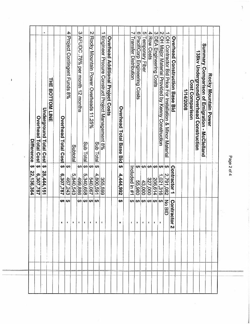
• Incremental cost: $22,136,364 o Base bid: $21,920,247 o Total cost: $28,444,151 (includes “additional project costs” not included in the bid).
• Undergrounding transmission lines costs $20,600,000 per mile.
2
Overhead Bid • This bid was obtained in order to determine the incremental cost of underground construction. • Base bid: $4,444,992 • Total cost: $6,307,787 (includes “additional project costs” not included in the bid). • Spectrum Engineers found that the overhead bid was accurate. The Spectrum Engineers bid review is
attached.
MATTERS AT ISSUE 1. The Council may wish to consider the cost to customers to convert from overhead to underground –
estimated at $2,000/connection. Three customers would be affected.
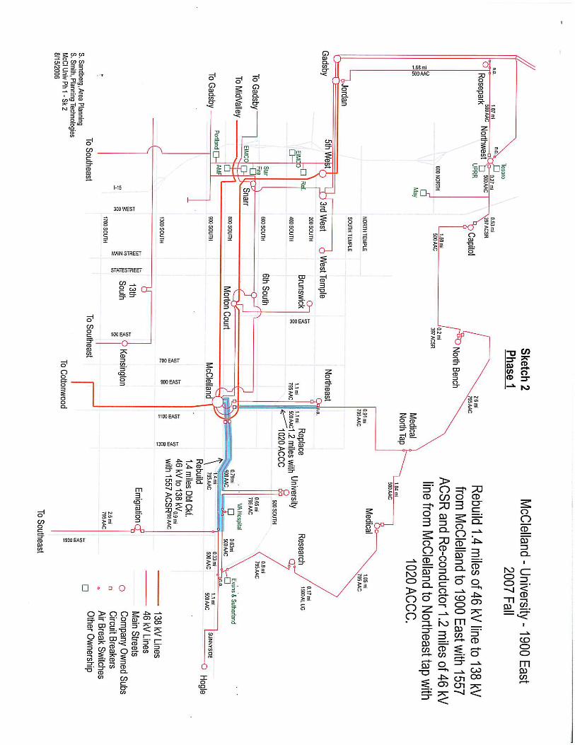
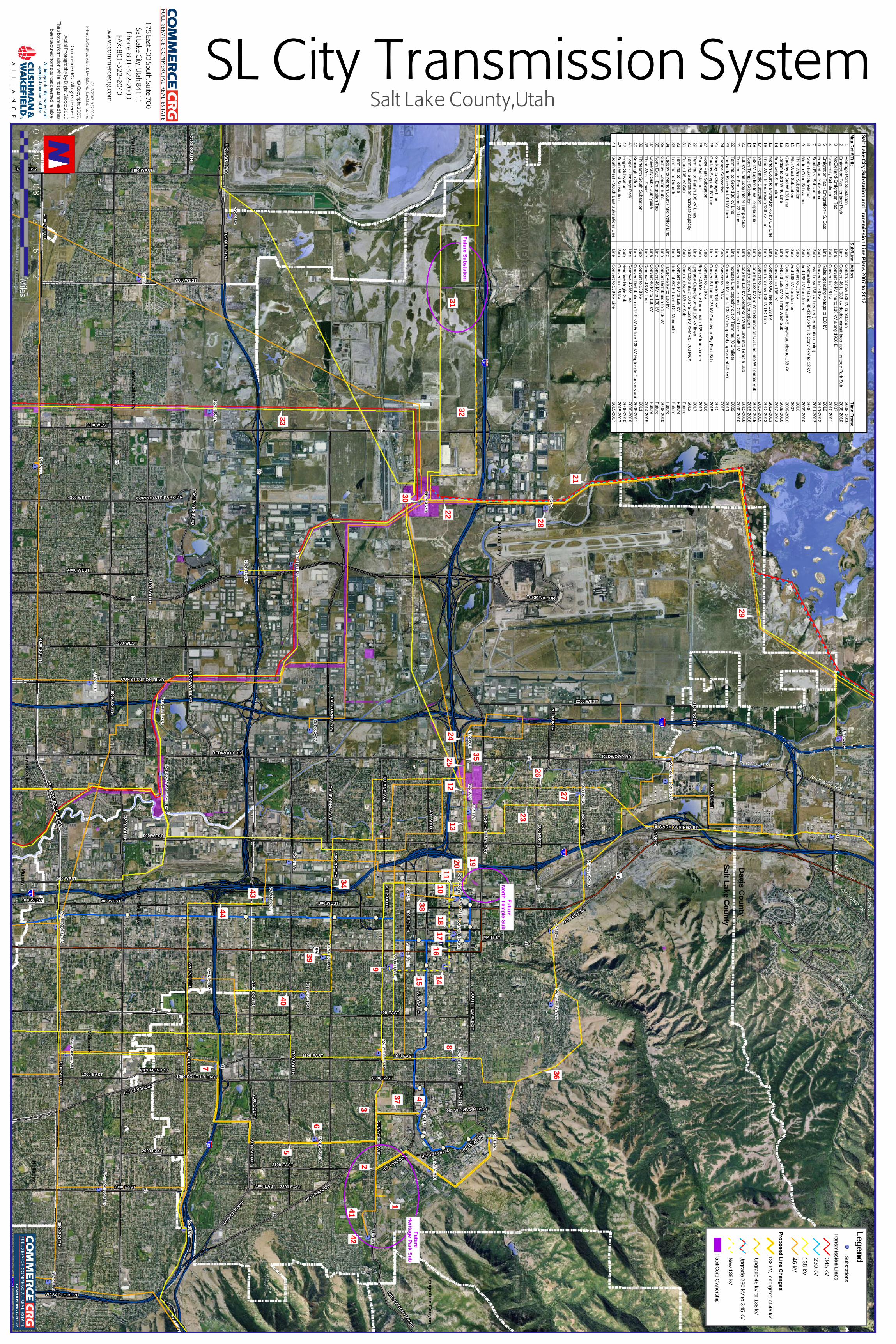
2. The Council may wish to consider the precedent that could be set if there is a decision to underground this portion of 800 South, as there are future upgrade projects (46 kV to 138 kV) that are likely from Rocky Mountain Power. For example, approximately 42 miles of overhead lines now built and operated at 46 kV are planned for future upgrade to 138 kV construction, 29 miles of which are located west of I-15. A map provided by Rocky Mountain Power on Salt Lake City’s existing and planned Transmission System is attached.
3. Underground conversion will require several large above ground structures. Example photos are attached.
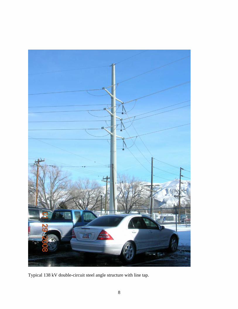
4. Upgrading the existing overhead system will require larger and taller poles. Example photos are attached.
5. The price of steel and copper could change, and will most likely increase as time goes on, therefore increasing the price of the project.
6. The Council could consider requiring that alternatives to transmission and distribution line upgrades and expansions be explored before moving forward with the upgrade or expansion.
7. The cost of undergrounding transmission lines is significantly more than undergrounding distribution lines. If the Council were to consider a policy on undergrounding power lines, the difference between distribution and transmission could be considered.
8. A detailed report on benefits and issues of undergrounding power can be provided upon request from Council Staff.
FUNDING OPTIONS 1. SID
a. City-wide: Create a City-wide SID to pay for the costs of the Emigration-McClelland 138 kV Line undergrounding project. City Council Staff would need to work with the Administration to determine the impact per household for this option.
b. Local SID: Create a local SID for affected property owners to pay the costs of the Emigration-McClelland 138 kV Line undergrounding project. Assuming 200 properties would share the cost of the $22.1 million project, over the typical term of an SID (10 Years) at a rate of 4%, the amount per property would be $13,630 per year.
2. GO Bond Place an initiative on the ballot in June for property owners to vote to authorize a property tax increase to finance this project. According to Council Staff estimates, assuming recent GO Bond interest and term scenarios, a $22.1 million GO bond would mean an approximate $14.00 per year increase on a home valued at $200,000 and a $130.00 per year increase on business property valued at $1 million. It should be noted that this levy would only pay for this project, and would not provide a financing tool for future undergrounding needs.
3
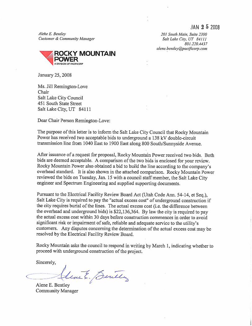
3. City-wide property Tax Increase and/or Sales Tax Bond The City Council could elect to increase property taxes (through a truth-in-taxation hearing), and issue a sales tax bond to pay for the project. Annual debt service on a sales tax bond for $22.1 million is approximately $1.8 million. In order to generate this yearly revenue, the Council could raise taxes by approximately $15.00 on a residential property valued at $200,000 and approximately $133.00 on a commercial property valued at $1 million. It should be noted that this levy would only pay for this project, and would not provide a financing tool for future undergrounding needs. ATTACHMENTS 1. Letter from Alene Bentley, Community Manager of Rocky Mountain Power, informing the Salt Lake City
Council of the receipt of two acceptable bids for undergrounding the 800 South project. The letter details a timeframe for response and the actual excess cost of the underground project. Included in the letter are spreadsheets detailing the cost of the bids and diagrams of the existing and future systems in the project area.
2. Response from Rocky Mountain Power regarding information requested by Council Staff. This
information includes photos of structures needed for the underground system and structures that would be required for the 138 kV overhead structures.
3. Map of Rocky Mountain Power’s Salt Lake City Transmission System.
4. Rocky Mountain Power Benchmark of Underground Transmission Policies and Practices.
5. Spectrum Engineers report on the Emigration – McClelland Tap 138 kV Line Underground vs. Overhead
Transmission Project Cost Comparison and Bid Review.


1
McClelland-Emigration 138 kV Project Information requested by Salt Lake City Council
Jan. 28, 2008 Number of customers that require UG/OH conversion:
Three customers are served directly from the line on 800 South/Sunnyside Ave. between McClelland Street and 1900 East. If the transmission line were constructed underground, these customers would need to convert their electrical service to underground where it enters their building.
Future transmission upgrades:
Per the map conveyed on Jan. 15, 2008 with the bid comparison: Approximately seven miles of overhead line now operated at 46 kV but constructed at 138 kV will be operated at 138 kV in the future.
Approximately 42 miles of overhead line now built and operated at 46 kV are
planned for future upgrade to 138 kV construction (29 miles of the 42 miles are West of I – 15). (Please refer to the large map delivered to the Salt Lake City Council for the Oct. 2, 2007 meeting with Rocky Mountain Power President Rich Walje.)

2
138 kV switch structure with 138 kV underground and overhead lines, 9400 South 2000 East. These structures are typically 80-100 feet tall. This is not a dead-end structure. Two switch structures will be required for McClelland-Emigration: one each at the University and VA taps, 1500 East and 1750 East Sunnyside.
3
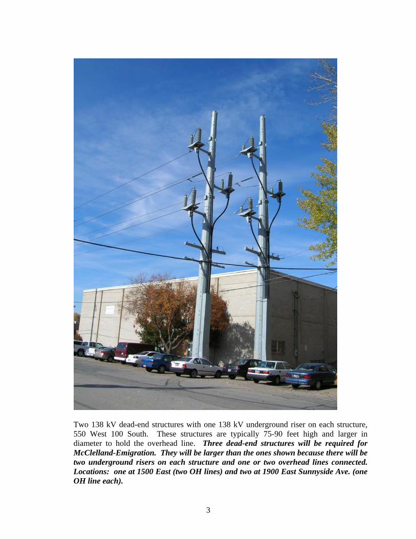
Two 138 kV dead-end structures with one 138 kV underground riser on each structure, 550 West 100 South. These structures are typically 75-90 feet high and larger in diameter to hold the overhead line. Three dead-end structures will be required for McClelland-Emigration. They will be larger than the ones shown because there will be two underground risers on each structure and one or two overhead lines connected. Locations: one at 1500 East (two OH lines) and two at 1900 East Sunnyside Ave. (one OH line each).

4
Two structures similar to this one will be installed inside McClelland Substation for underground construction.
Substation Structure

5
McClelland Emigration 138 kV line Typical Overhead Structures
The line will be built primarily with wood poles using steel poles for angles and dead-ends. The poles will average approximately 85 feet from ground level. See attached photos for typical overhead structures.
6
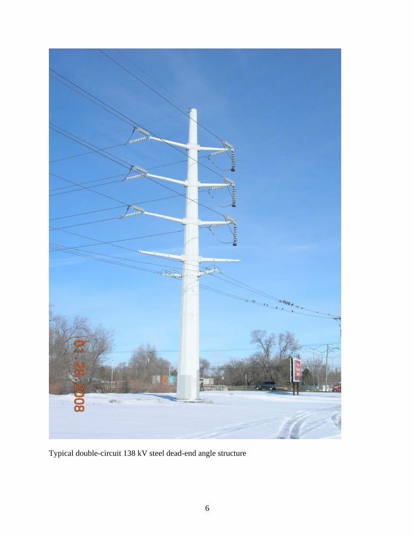
Typical double-circuit 138 kV steel dead-end angle structure

7
Typical 90 foot wood double-circuit 138 kV tangent structure with distribution.
8
Typical 138 kV double-circuit steel angle structure with line tap.
Salt Lake County
Davis C
ounty
30
29
28
27
26
2524
23
22
21
20
19
1718
16
15
14
1312
1110
9
8
7
5
6
4
32
137
39
40
38
34
36
4142
35
43
44
33
3231
5
00
W
est
SE
NSL
Gro
w
Ma
gn
a
Riter
Sn
arr
Ho
gle
Cu
da
hy
Ora
nge
Hu
nter
Ga
dsby
Jo
rda
n
Ca
nn
on
Pa
rk
way
Red
wo
od
Gra
nger
Ca
pita
l
Med
ica
l
Oa
kla
nd
Olym
pu
s
Term
in
al
Ro
sepa
rk
3rd
West
Resea
rch
Pa
rley’s
La
ke P
ark
Rid
gela
nd
No
rth
West
6th
So
uth
Mo
rto
n Ct
So
uth
west
Mid
va
lley
No
rth
Ea
st
Cen
ten
nia
l
McC
lella
nd
13
th
So
uth
Ken
sin
gto
n
Un
iversity
Em
igratio
n
Co
tto
nw
oo
d
Decker La
ke
West Tem
ple
No
rth
Ben
ch
Va
lley Cen
ter
Ea
st M
illcreek
Wa
satch
Sprin
gs
CE
NT
ER
ST
ORCHARD DR
EAGLE R
I DG
E D
R
BOUNTIFUL BLVD
REDWOOD RD
3800 SO
UT
H
REDWOOD RD
700 EAST
5600 WEST
4100 SOU
TH
1700 SOU
TH
2100 SOU
TH
1300 SOU
TH
3100 SOU
TH
3900 SOU
TH
800 SOU
TH
3200 WEST
2200 WEST
REDWOOD RD
HIGHLAND DR
7200 WEST
8400 WEST
400 SOU
TH
2300 EAST
4800 WEST
4000 WEST
2100 EAST
500 SOU
TH
600 SOU
TH
PAR
KW
AY
BLV
D2700 SO
UTH
900 WEST
500 WEST
U-201 EB
HW
Y
600 NO
RTH
U-201 W
B H
WY
1300 EAST
300 WEST
NO
RTH
TEMPLE ST
3500 SOU
TH
CONSTITUTION BLVD
3300 SOU
TH
SOU
TH TEM
PLE ST
VICTORY RD
1000 NO
RTH
SUN
NYSID
E AV
E
WASATCH BLVD
2000 EAST
MEA
DO
W B
RO
OK
EXPY
IND
IAN
A A
VE
TERMINAL DR
LAK
E PA
RK
BLVD
2300 NO
RTH
CA
LIFOR
NIA
AVE
RICHMOND ST
PARLEYS WAY
WASATCH DR
MEDICAL DR
EMIGRATION CYN RD
U-111 HWY
WARM SPRINGS RD
FOOTHILL DR
700 NO
RTH
MAIN ST
100 SOU
TH
1100 EAST
CORPORATE PARK DR
NORTH CAMPUS DR
1300 SOUTH B EAST
2100 NO
RTH
1800 NO
RTH
1100 EAST
2300 EAST
2100 SOU
TH
4100 SOU
TH
2700 SOU
TH
1300 EAST
300 WEST
3900 SOU
TH
REDWOOD RD
300 WEST
2300 EAST
2700 SOU
TH
2100 SOU
TH
CA
LIFOR
NIA
AVE
FOOTHILL DR
Salt Lake City
West Valley C
ityM
agna
Millcreek
South Salt Lake
Holladay
Taylorsville
Emigration C
anyon
Murray
SL City Transmission System
Salt Lake County
Davis C
ounty
30
29
28
27
26
2524
23
22
21
20
19
1718
16
15
14
1312
1110
9
8
7
5
6
4
32
137
39
40
38
34
36
4142
35
43
44
33
3231
5
00
W
est
SE
NSL
Gro
w
Ma
gn
a
Riter
Sn
arr
Ho
gle
Cu
da
hy
Ora
nge
Hu
nter
Ga
dsby
Jo
rda
n
Ca
nn
on
Pa
rk
way
Red
wo
od
Gra
nger
Ca
pita
l
Med
ica
l
Oa
kla
nd
Olym
pu
s
Term
in
al
Ro
sepa
rk
3rd
West
Resea
rch
Pa
rley’s
La
ke P
ark
Rid
gela
nd
No
rth
West
6th
So
uth
Mo
rto
n Ct
So
uth
west
Mid
va
lley
No
rth
Ea
st
Cen
ten
nia
l
McC
lella
nd
13
th
So
uth
Ken
sin
gto
n
Un
iversity
Em
igratio
n
Co
tto
nw
oo
d
Decker La
ke
West Tem
ple
No
rth
Ben
ch
Va
lley Cen
ter
Ea
st M
illcreek
Wa
satch
Sprin
gs
CE
NT
ER
ST
ORCHARD DR
EAGLE R
I DG
E D
R
BOUNTIFUL BLVD
REDWOOD RD
3800 SO
UT
H
REDWOOD RD
700 EAST
5600 WEST
4100 SOU
TH
1700 SOU
TH
2100 SOU
TH
1300 SOU
TH
3100 SOU
TH
3900 SOU
TH
800 SOU
TH
3200 WEST
2200 WEST
REDWOOD RD
HIGHLAND DR
7200 WEST
8400 WEST
400 SOU
TH
2300 EAST
4800 WEST
4000 WEST
2100 EAST
500 SOU
TH
600 SOU
TH
PAR
KW
AY
BLV
D2700 SO
UTH
900 WEST
500 WEST
U-201 EB
HW
Y
600 NO
RTH
U-201 W
B H
WY
1300 EAST
300 WEST
NO
RTH
TEMPLE ST
3500 SOU
TH
CONSTITUTION BLVD
3300 SOU
TH
SOU
TH TEM
PLE ST
VICTORY RD
1000 NO
RTH
SUN
NYSID
E AV
E
WASATCH BLVD
2000 EAST
MEA
DO
W B
RO
OK
EXPY
IND
IAN
A A
VE
TERMINAL DR
LAK
E PA
RK
BLVD
2300 NO
RTH
CA
LIFOR
NIA
AVE
RICHMOND ST
PARLEYS WAY
WASATCH DR
MEDICAL DR
EMIGRATION CYN RD
U-111 HWY
WARM SPRINGS RD
FOOTHILL DR
700 NO
RTH
MAIN ST
100 SOU
TH
1100 EAST
CORPORATE PARK DR
NORTH CAMPUS DR
1300 SOUTH B EAST
2100 NO
RTH
1800 NO
RTH
1100 EAST
2300 EAST
2100 SOU
TH
4100 SOU
TH
2700 SOU
TH
1300 EAST
300 WEST
3900 SOU
TH
REDWOOD RD
300 WEST
2300 EAST
2700 SOU
TH
2100 SOU
TH
CA
LIFOR
NIA
AVE
FOOTHILL DR
Salt Lake City
West Valley C
ityM
agna
Millcreek
South Salt Lake
Holladay
Taylorsville
Emigration C
anyon
Murray
175 East 400 South, Suite 700Salt Lake City, U
tah 84111Phone: 801-322-2000
FAX: 801-322-2040w
ww
.comm
ercecrg.com
© C
opyright 2007.Com
merce CRG
. All rights reserved.Aerial Photography by D
igitalGlobe; 2006
The above information w
hile not guaranteed hasbeen secured from
sources deemed reliable.
8/13/2007 9:57:00 AMF:\Projects\Kirkt\PacifiCorp\U
TAH\SLCo\SaltLakeCtyLines.m
xd
00.4
0.81.2
1.62
0.2M
iles
Salt Lake County,Utah
FutureH
eritage Park Sub
FutureN
orth Temple Sub
Future Substation
LegendSubstations
PacifiCorp O
wnership
Transmission Lines
345 kV
230 kV
138 kV
46 kV
Proposed Line Changes
138 kV, energized at 46 kV
Upgrade 46 kV
to 138 kV
Upgrade 230 kV to 345 kV
New
138 kV
Salt Lake City Substation and Transm
ission Line Plans 2007 to 2017
Map R
ef #Tiitle
Sub/LineAction
Time Fram
e1
Heritage P
ark Substation
Sub
Construct new
138 kV substation
2008 -20102
Em
igration Tap-Heritage P
arkLine
Convert 46 to 138 kV
double circuit loop into Heritage P
ark Sub
2008-20103
McC
lelland-Em
igration TapLine
Convert 46 kV
line to 138 kV along 1900 E
20074
University S
ubstationS
ubC
onvert to 138 kV2010-2011
5E
migration Tap - E
migration - S
. East
LineR
aise operating voltage to 138 kV2012
6E
migration S
ubstationS
ubC
onvert to 138 kV2011-2012
7S
outh East S
ubstationS
ubInstall new
138 kV breaker (term
ination point)2011-2012
8N
orth East S
ubstationS
ubN
ortheast - Inst 2nd 46-12 kV xfm
r & C
onv 4kV to 12 kV
20089
Morton C
ourt Substation
Sub
Add 138 kV
transformer
2009-201010
Third West S
ubstationS
ubC
onvert to 138 kV2010
11Fifth W
est Substation
Sub
Add 138 kV
transformer
200712
Gadsby to 3rd W
138 LineLine
Double circuit 138, increase 46 operated side to 138 kV
2009-201013
Jordan to 3rd W 46 Line
LineR
ebuild 138 kV to Third W
est Sub
2009-201014
Brunsw
ich Substation
Sub
Convert to 138 kV
2012-201315
Morton C
ourt to Brunsw
ich 46 kV U
G Line
LineC
onvert to UG
line to 138 kV2012-2013
16Thrid W
est to Brunsw
ich 138 kv LineLine
Construct new
138 kV U
G Line
2012-201317
West Tem
ple Substation
Sub
Convert to 138 kV
2014-201518
138 kV Tap line to W
Temple S
ubLine
Loop the 138 kV 3rd W
to Brunsw
ich UG
Line into W Tem
ple Sub
2014-201519
North Tem
ple Substation
Sub
Construct new
138 kV substation
2015-201620
138 kV Line Loop into N
Temple S
ubLine
Loop the 138 kV Jordan-5th W
est Line into Temple S
ub2015-2016
21Term
inal to Ben Lom
ond 230 LineLine
Convert double circuit 230 kV
Line to 345 kV2009-2010
22Term
inal to Grow
138 kV Line
LineIncrease Line capacity out of Term
inal (0.5 miles)
200923
Jordan to Rose P
ark 46 kV Line
LineC
onvert 46 kV line to 138 kV
(temporarly operate at 46 kV
)2011
24O
range Substation
Sub
Convert to 138 kV
201525
Gadsby to O
range LineLine
Convert line to 138 kV
201526
Gadsby-S
kypark "B" Line
LineC
onvert B Line to 138 kV
Gadsby to S
ky Park S
ub2015
27R
ose Park S
ubstationS
ubC
onvert to 138 kV2016
28G
row S
ubstationS
ubR
eplce 46 kV transform
er with 138 kV
transformer
201729
Terminal to P
arish 138 kV Lines
LineU
pgrade Capacity on all 138 kV
lines2017
30Term
inal Substation increase capacity
Sub
Incr Cap # 9&
# 10 345-138 kV XFM
Rs - 700 M
VA
201231
Future 138 kV S
ubS
ubC
onstruct New
138 kV S
ubFuture
32Term
inal to TooeleLine
Convert 46 kV
to 138 kVFuture
33Term
inal to Oquirrh
LineR
ebuild SC
H-Fram
e DC
Monopole
Future34
Gadsby to M
orton Court / M
id Valley Line
LineFuture 46 kV
to 138 kVFuture
35G
adsby - Jordan Subs
LineC
onvert Distribtuion to 12.5 kV
2008-201036
North E
ast - Em
igration TapLine
Convert 46 kV
to 138 kVFuture
37U
niversity Sub - S
unnysideLine
Convert 46 kV
to 138 kVFuture
38Third W
est - Snarr
LineR
emove 46 kV
Line2014-2015
39Thirteenth S
outh Substation
Sub
Convert to 138 kV
201140
Kensington S
ubLine
Convert D
istribution to 12.5 kV (Future 138 kV
High side C
onversion)2009-2011
41H
ogle - Heritage P
arkLine
Rem
ove 46 kV Line
2008-201042
Hogle S
ubstationS
ubR
emove H
ogle Sub
2008-201043
South W
est Substation
Sub
Convert to 138 kV
2015-201744
South W
est - South E
ast Substations Line
LineC
onvert to 138 kV Line
2015-2017
1
Rocky Mountain Power Benchmark of
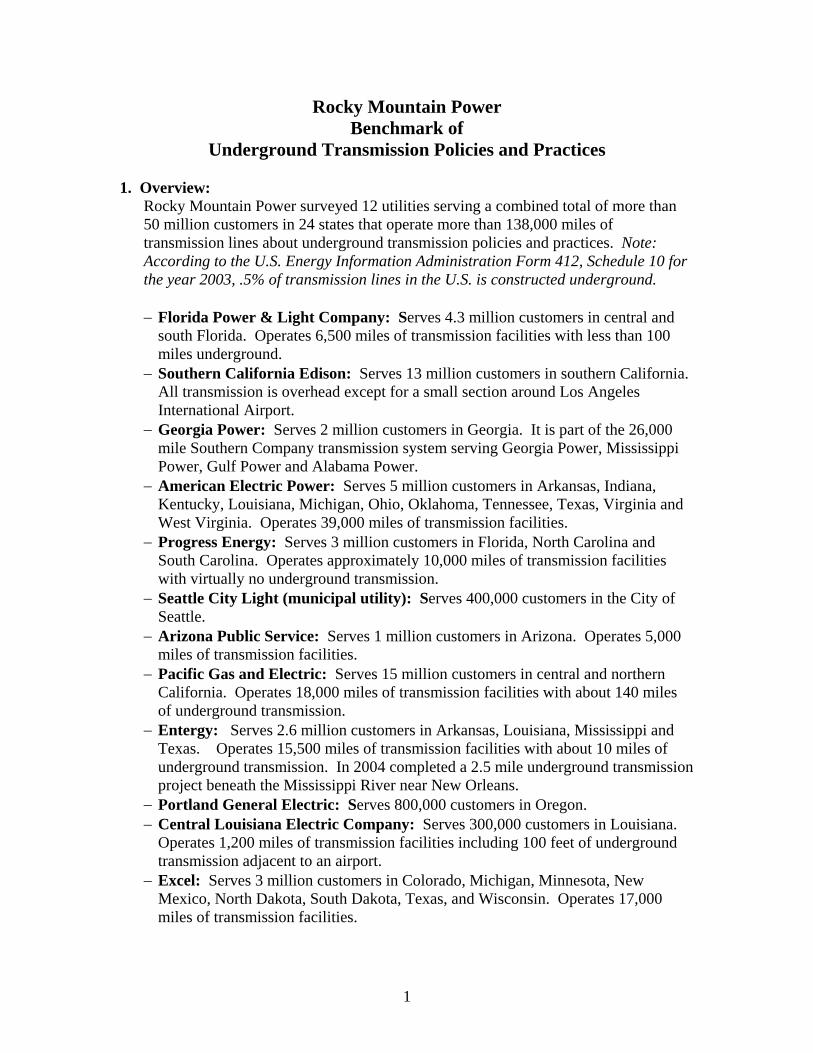
Underground Transmission Policies and Practices 1. Overview:
Rocky Mountain Power surveyed 12 utilities serving a combined total of more than 50 million customers in 24 states that operate more than 138,000 miles of transmission lines about underground transmission policies and practices. Note: According to the U.S. Energy Information Administration Form 412, Schedule 10 for the year 2003, .5% of transmission lines in the U.S. is constructed underground.
− Florida Power & Light Company: Serves 4.3 million customers in central and
south Florida. Operates 6,500 miles of transmission facilities with less than 100 miles underground.
− Southern California Edison: Serves 13 million customers in southern California. All transmission is overhead except for a small section around Los Angeles International Airport.
− Georgia Power: Serves 2 million customers in Georgia. It is part of the 26,000 mile Southern Company transmission system serving Georgia Power, Mississippi Power, Gulf Power and Alabama Power.
− American Electric Power: Serves 5 million customers in Arkansas, Indiana, Kentucky, Louisiana, Michigan, Ohio, Oklahoma, Tennessee, Texas, Virginia and West Virginia. Operates 39,000 miles of transmission facilities.
− Progress Energy: Serves 3 million customers in Florida, North Carolina and South Carolina. Operates approximately 10,000 miles of transmission facilities with virtually no underground transmission.
− Seattle City Light (municipal utility): Serves 400,000 customers in the City of Seattle.
− Arizona Public Service: Serves 1 million customers in Arizona. Operates 5,000 miles of transmission facilities.
− Pacific Gas and Electric: Serves 15 million customers in central and northern California. Operates 18,000 miles of transmission facilities with about 140 miles of underground transmission.
− Entergy: Serves 2.6 million customers in Arkansas, Louisiana, Mississippi and Texas. Operates 15,500 miles of transmission facilities with about 10 miles of underground transmission. In 2004 completed a 2.5 mile underground transmission project beneath the Mississippi River near New Orleans.
− Portland General Electric: Serves 800,000 customers in Oregon. − Central Louisiana Electric Company: Serves 300,000 customers in Louisiana.
Operates 1,200 miles of transmission facilities including 100 feet of underground transmission adjacent to an airport.
− Excel: Serves 3 million customers in Colorado, Michigan, Minnesota, New Mexico, North Dakota, South Dakota, Texas, and Wisconsin. Operates 17,000 miles of transmission facilities.
2
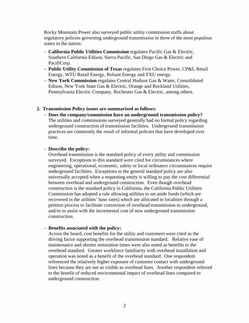
Rocky Mountain Power also surveyed public utility commission staffs about regulatory policies governing underground transmission in three of the most populous states in the nation:
− California Public Utilities Commission regulates Pacific Gas & Electric, Southern California Edison, Sierra Pacific, San Diego Gas & Electric and PacifiCorp.
− Public Utility Commission of Texas regulates First Choice Power, CP&L Retail Energy, WTU Retail Energy, Reliant Energy and TXU energy.
− New York Commission regulates Central Hudson Gas & Water, Consolidated Edison, New York State Gas & Electric, Orange and Rockland Utilities, Pennsylvania Electric Company, Rochester Gas & Electric, among others.
2. Transmission Policy issues are summarized as follows:
− Does the company/commission have an underground transmission policy? The utilities and commissions surveyed generally had no formal policy regarding underground construction of transmission facilities. Underground transmission practices are commonly the result of informal policies that have developed over time.
− Describe the policy:
Overhead transmission is the standard policy of every utility and commission surveyed. Exceptions to this standard were cited for circumstances where engineering, operational, economic, safety or local ordinance circumstances require underground facilities. Exceptions to the general standard policy are also universally accepted when a requesting entity is willing to pay the cost differential between overhead and underground construction. Even though overhead construction is the standard policy in California, the California Public Utilities Commission has adopted a rule allowing utilities to set aside funds (which are recovered in the utilities’ base rates) which are allocated to localities through a petition process to facilitate conversion of overhead transmission to underground, and/or to assist with the incremental cost of new underground transmission construction.
− Benefits associated with the policy:
Across the board, cost benefits for the utility and customers were cited as the driving factor supporting the overhead transmission standard. Relative ease of maintenance and shorter restoration times were also noted as benefits to the overhead standard. Greater workforce familiarity with overhead installation and operation was noted as a benefit of the overhead standard. One respondent referenced the relatively higher exposure of customer contact with underground lines because they are not as visible as overhead lines. Another respondent referred to the benefit of reduced environmental impact of overhead lines compared to underground construction.

3
− Risks associated with the policy: Community/public opposition to the aesthetic impacts of transmission lines.
− Cost (capital and operational) considerations associated with the policy:
Surveyed utilities estimated the capital cost of underground transmission to be 3-15 times more costly than overhead transmission. The survey respondents universally noted longer and more costly restoration activities associated with underground transmission. With regard to routine operation and maintenance costs, the survey revealed no clear consensus related to differences between overhead and underground. This may be related to the fact that many utilities had very little experience with underground transmission. However, limited workforce experience with underground transmission may account for higher operating costs.
− Easement congestion considerations:
Congestion of underground easement corridors can lead to increased capital, operating and operation costs. However, it was also noted by a survey respondent that congestion of overhead easement corridors may potentially force underground construction in certain circumstances.
− Reliability considerations associated with the policy:
There was no clear consensus on whether underground transmission is more reliable than overhead transmission. Some respondents stated that underground facilities are more reliable than overhead facilities. One respondent observed that while they are not subject to wind and collisions, underground facilities are subject to outages caused by lightning strikes, flooding, and wind damaging above ground transformers. Another survey respondent noted that underground transmission is more reliable until it reaches the latter stages of its useful life (20 to 25 years) and then it is less reliable than overhead facilities. Survey respondents unanimously acknowledged that outage restoration of underground facilities is a matter of days (perhaps even weeks) as opposed to hours for overhead facilities.
− Customer/community relations considerations associated with the policy:
Resistance to undergrounding may result in strained relations with customers and communities, potentially jeopardizing other community initiatives of the utility.
− Regulatory considerations associated with the policy:
The California Public Utilities Commission has adopted a rule to set aside a limited amount of funds (recoverable by the utility in base rates) to facilitate underground projects sponsored by localities. Local government may petition the commission to utilize the funds. Additionally, the Florida Public Service Commission has encouraged Florida Power to strengthen its delivery system as a result of recent hurricane impacts. Florida Power’s proposed response is to focus resources on underground distribution feeders and to strengthen overhead transmission, but not to underground transmission, as the impact of such an approach could result in unacceptably high rate increases. Beyond these limited situations, the survey

4
revealed that utility regulators are not encouraging utilities to underground transmission facilities.
− Other considerations associated with the policy:
Commission rules in some states require an application and an approved Certificate of Convenience and Public Necessity (CCPN) before a transmission project can be built. These proceedings are time consuming and attract participation of numerous parties with interest in transmission siting and construction. Often these proceedings are contentious and result in changes to the utilities’ proposed projects, including rerouting and/or undergrounding of portions of transmission facilities. While such proceedings can be burdensome for the utility, an approved CCPN provides support (but not a guarantee) for recovery of related costs in the context of rate case proceedings.
3. Transmission Operational issues: − Contingency design criteria for underground transmission:
Generally N-2 is the standard with exceptions up to N-4 in metro areas such as San Francisco.
− Installed redundancy for underground transmission:
Generally some degree of redundancy, such as spare conduit and cable, is installed with new transmission construction. However the level of built-in redundancy appears to be determined on a project-by-project basis and not as a matter of policy.
− Loading criteria applied to the cable:
Generally 100% of the cable rating, except Seattle City Light which was 80% of rating.
− Spare parts inventory levels:
Generally, spare parts inventory is maintained for the longest underground span in the system with associated cable, splices, and termination.
− Personnel and training:
Transmission underground work is usually contracted out, so there is generally no specialized company workforce trained for underground installation, operation, or maintenance.
− Non-utility built facilities:
On a case-by-case basis, the utilities may allow non-utility entities to build portions (duct banks, etc.) of underground facilities to utility standards. Some utilities may not allow non-utility work, other than direct contractors, on the actual cables, splices and terminations.
− Exchange of construction standards documents:
Utilities are generally open to the idea, however further discussions would be required to specifically identify the type of information to be shared or exchanged.

P:\2008\20080046\00Communications\Correspondence\0046 Report.doc
Emigration – McClelland Tap 138 kV Line Underground vs. Overhead
Transmission Project Cost Comparison and Bid Review - Report Jill Remington Love Chair, Salt Lake City Council PO Box 145476 Salt Lake City, UT 84114-5476 Spectrum Job # 20070046 January 29, 2008 Project Description: The City Council of Salt Lake City engaged Spectrum Engineers to review the design, technical specifications and bids for the Emigration-McClelland 138 kV Line Underground Transmission Project (the “Project”). The intent of the review is to determine whether the bid prices provided by the electrical contractors are reasonable for completing the Project. Specifications for the project were in accordance with the standards of Rocky Mountain Power (RMP) and a preliminary design done by Tri-Axis Engineering of Corvallis, Oregon. The line will be built by an contractor, with the difference in cost between overhead and underground installation being paid for by the city and owned by RMP. Executive Summary: A 138 kV underground transmission line is a highly specialized project specific design. The RMP approach of having the cable installation designed and warranted by the cable manufacture is a good decision. The underground design was preliminary, about a 25% design level, but described the work to be done adequately enough for the contractors to prepare bids. The overhead design was a construction bid design level and thus the overhead proposal was more accurate. Based on the limited amount of cost data that could be found on the Internet, the difference in the estimated cost between overhead and underground is justified. Discussion:
1. To determine the evenhandedness of the underground cost, this engineer endeavored to compare the cost per mile for this project to that of other 138 kV projects. The low bid from Wasatch Electric was $28,444,151, which equates to $20,600,000 per mile. The cost for overhead was $6,307,787. Testimony given to

175 S. Main, Ste 300, SLC, UT 84111 801-328-5151 • 800-678-7077 www.spectrum-engineers.com Fax: 801-328-5155
HEALTHCARE • HIGHER EDUCATION • EDUCATION K-12 • GOVERNMENT • HOUSES OF WORSHIP • SPECIAL PROJECTS
MECHANICAL ENGINEERING • ELELECTRICAL ENGIENEERING • TECHNOLOGY DESIGN • LIGHTING DESIGN • ACOUSTICAL ENGINEERING • THEATRE DESIGN
the Board of Trustees of the Long Island Power Authority states that “138 kV underground lines are approximately six times as costly as overhead lines” 1. The Emigration Project underground cost was 4.5 times that of the overhead. A study done in Long Island found that the cost, for a 115 kV line run over head was between $1.1 and $0.83 million dollars per mile versus $5.0 to $5.65 million dollars per mile for underground 2. A 3.6 mile long underground 138 kV line in Hawaii cost $110 million or $30.55 million per mile3.
2. The number one reason for the high cost of this project is that very few high
voltage (115 kV to 230 kV) underground transmission lines are built in the United States. Less than ¼ of 1% of all of the 138 kV lines in this country are underground. This means that there is no standard equipment, available off the shelf, to do this work. Everything is special order. The 3000 MCM conductor supplied for this project would be different from the conductor made by another manufacturer. Similarly, even a company as large as Pacific Corp does not have engineering standards for underground high voltage lines. All of the engineering is new for each project.
3. The conductor in the bids is Southwire. In terms of cost, Southwire is a middle tier
cable manufacturer. They are a reputable company that is an allowed vendor in Spectrum’s standard specification for medium voltage conductor. Based on past experience RMP has determined that to get a reliable product it is best to have the cable manufacturer design and warrant the entire cable system including equipment terminations, splices and conductor. This engineer agrees with this approach because it ensures that all of the components are going to work together to provide a safe and reliable system. Selecting components from various manufacturer’s, based on cost, assumes interchangeability between manufacturers that just does not exist. The cable design could only be made less expensive by sacrificing reliability. This ultimately would not be good for the City or RMP.
4. A little less than one fourth of the construction cost is for the 138 kV cable
($6,096,130). The cost of copper is at record high levels and fluctuates so rapidly that the cable manufacturers will not provide a firm cost until the day the order is received. Based on this the cost of the project will most likely increase by the amount of the inflation in cable cost.
5. The design and construction of the medium voltage (12.5 kV) under built line and
its underground replacement is required by RMP to be built to their specifications and standards. This does not allow any value engineering. This engineer agrees with RMP’s position that this is necessary to ensure the reliability of the system. It will not help the growth of the City if there are lengthy power outages because a less expensive non-standard part is installed in the system fails and there are no replacement parts in the warehouse.

175 S. Main, Ste 300, SLC, UT 84111 801-328-5151 • 800-678-7077 www.spectrum-engineers.com Fax: 801-328-5155
HEALTHCARE • HIGHER EDUCATION • EDUCATION K-12 • GOVERNMENT • HOUSES OF WORSHIP • SPECIAL PROJECTS
MECHANICAL ENGINEERING • ELELECTRICAL ENGIENEERING • TECHNOLOGY DESIGN • LIGHTING DESIGN • ACOUSTICAL ENGINEERING • THEATRE DESIGN
Additional Data: An excellent explanation and discussion of overhead versus underground power transmission was given in the “Comprehensive Assessment and Report” on Southwest Connecticut1. A portion of the report is included below.
Electric Transmission Technology
Overhead electric transmission lines and their rights-of-way (ROW) mark the landscape throughout Connecticut and the U.S. as a whole. Whereas some commercial and virtually all new residential subdivisions have begun using underground distribution lines in recent years, underground high-voltage transmission cables in Connecticut are limited to small sections in Hartford, New Haven, Stamford, Danbury and Norwalk and to some small generator interconnections. To date, cable accessibility restrictions, maintenance requirements, technical limitations, and the availability of existing ROW for overhead lines have restricted use of high voltage underground cables to a few urban areas and generator interconnections. Connecticut law (CGS Sec. 16-50t(a), requires the Siting Council to prescribe and establish reasonable regulations and standards as it deems necessary and in the public interest relating to “the elimination of overhead electric transmission and distribution lines over appropriate periods of time in accordance with existing applicable technology and the need to provide electric service at the lowest reasonable cost to consumers.” CGS 16-50r(b) mandates that the Siteing Council commission periodic reports on the comparative life-cycle costs of underground versus overhead transmission lines. These studies, based on an analysis of 115-kV line only, concluded that initial construction costs for underground transmission lines are five to six times as expensive as overhead lines. When only expenses and losses are included, the life-cycle cost of a typical single-circuit underground line is estimated to be three to four times that of an overhead single-circuit line, and the life-cycle cost of a double circuit underground transmission line is five times as much as for overhead double circuit lines1. It is important to note that actual cost differentials are very site-specific and may also be a function of line voltage, for example, the estimated cost of the Bethel-Norwalk 345 kV underground project is higher than the overhead alternative. Although both underground and overhead components have experienced incremental improvements in performance through industry’s greater attention to quality and competitive pricing, the reported differential between underground and overhead lines has not changed appreciably between the initial 1996 study and the 2001 update.
Overhead Electric Transmission
Transmission lines are generally designed and built to provide safe, reliable performance over a life of at least 35-40 years. All electric transmission lines are designed to comply with the National Electrical Safety Code (NESC). NESC establishes worker safety requirements for line maintenance, ROW requirements, engineering design criteria for conductors and towers, and other safety, operational and performance specifications. The height and ROW requirements of NESC ensure that swinging conductors do not come in contact with nearby buildings or vegetation, even during worst-case line-sag scenarios. Nearly the entire electrical grid in the U.S. and the world consists of overhead AC lines. As a rule of thumb, a doubling in voltage capacity corresponds to a 2.5 to 3.5-fold increase in power delivery capacity.2 The
1 The life-cycle cost estimates and the projected costs of the proposed Bethel-Norwalk 345 kV project are discussed in Section. 2 Transmission losses are a function of the square of the voltage.
175 S. Main, Ste 300, SLC, UT 84111 801-328-5151 • 800-678-7077 www.spectrum-engineers.com Fax: 801-328-5155
HEALTHCARE • HIGHER EDUCATION • EDUCATION K-12 • GOVERNMENT • HOUSES OF WORSHIP • SPECIAL PROJECTS
MECHANICAL ENGINEERING • ELELECTRICAL ENGIENEERING • TECHNOLOGY DESIGN • LIGHTING DESIGN • ACOUSTICAL ENGINEERING • THEATRE DESIGN
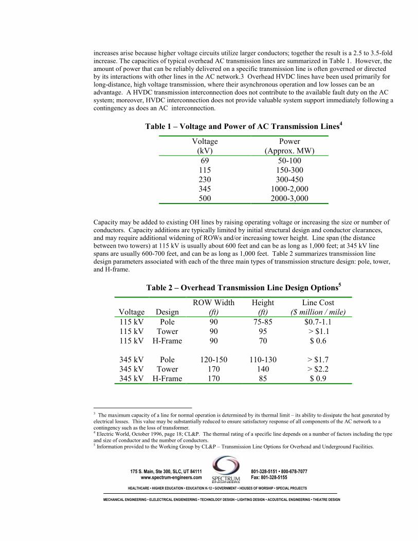
increases arise because higher voltage circuits utilize larger conductors; together the result is a 2.5 to 3.5-fold increase. The capacities of typical overhead AC transmission lines are summarized in Table 1. However, the amount of power that can be reliably delivered on a specific transmission line is often governed or directed by its interactions with other lines in the AC network.3 Overhead HVDC lines have been used primarily for long-distance, high voltage transmission, where their asynchronous operation and low losses can be an advantage. A HVDC transmission interconnection does not contribute to the available fault duty on the AC system; moreover, HVDC interconnection does not provide valuable system support immediately following a contingency as does an AC interconnection.
Table 1 – Voltage and Power of AC Transmission Lines4
Voltage (kV)
Power (Approx. MW)
69 50-100 115 150-300 230 300-450 345 1000-2,000 500 2000-3,000
Capacity may be added to existing OH lines by raising operating voltage or increasing the size or number of conductors. Capacity additions are typically limited by initial structural design and conductor clearances, and may require additional widening of ROWs and/or increasing tower height. Line span (the distance between two towers) at 115 kV is usually about 600 feet and can be as long as 1,000 feet; at 345 kV line spans are usually 600-700 feet, and can be as long as 1,000 feet. Table 2 summarizes transmission line design parameters associated with each of the three main types of transmission structure design: pole, tower, and H-frame.
Table 2 – Overhead Transmission Line Design Options5
Voltage Design ROW Width
(ft)
Height (ft)
Line Cost ($ million / mile)
115 kV Pole 90 75-85 $0.7-1.1 115 kV Tower 90 95 > $1.1 115 kV H-Frame 90 70 $ 0.6
345 kV Pole 120-150 110-130 > $1.7 345 kV Tower 170 140 > $2.2 345 kV H-Frame 170 85 $ 0.9
3 The maximum capacity of a line for normal operation is determined by its thermal limit – its ability to dissipate the heat generated by electrical losses. This value may be substantially reduced to ensure satisfactory response of all components of the AC network to a contingency such as the loss of transformer. 4 Electric World, October 1996, page 18; CL&P. The thermal rating of a specific line depends on a number of factors including the type and size of conductor and the number of conductors. 5 Information provided to the Working Group by CL&P – Transmission Line Options for Overhead and Underground Facilities.

175 S. Main, Ste 300, SLC, UT 84111 801-328-5151 • 800-678-7077 www.spectrum-engineers.com Fax: 801-328-5155
HEALTHCARE • HIGHER EDUCATION • EDUCATION K-12 • GOVERNMENT • HOUSES OF WORSHIP • SPECIAL PROJECTS
MECHANICAL ENGINEERING • ELELECTRICAL ENGIENEERING • TECHNOLOGY DESIGN • LIGHTING DESIGN • ACOUSTICAL ENGINEERING • THEATRE DESIGN
Structure support the lines on insulators made of ceramic disks or nonceramic rods that insulate the lines from the rest of the tower. Ceramic insulators are an old technology; nonceramic insulators have several advantages, primarily decreased weight and increased strength. Lightning arresters and surge arresters, usually a series of air gaps or semiconductor devices, improve reliability by dissipating impulse or switching surge over-voltages on the line. Shield or sound wires and ground wires, which run above and parallel to the conducting wire, serve to shunt lighting strikes from the conducting wire to the ground.
Environmental Impacts of Overhead Electric Transmission
Vegetation and Wildlife Impacts – Overhead transmission line ROWs usually involve clearing corridors of vegetation to remove trees and tall shrubs. Clearing within previously undisturbed areas can significantly alter wildlife habitat, converting, for example, forest to open grassland or shrubland. Non-native species often invade recently cleared corridors and out-compete native vegetation. Once established in the ROW, the non-native species may invade the adjoining floral communities, to the detriment of those areas. The dominance of non-native invasive species reduces the floral species diversity and in turn reduces the diversity of the faunal community. ROWs may reduce core habitat area (interior forest habitat that is free of edge effects) necessary to support a breeding population of locally important wildlife, including rare, threatened, or endangered species. Transmission line ROWs may have beneficial impacts on certain wildlife habitat. ROWs serve as corridors for wildlife movement and provide scrub-shrub habitat and edge habitat that is beneficial to some wildlife species. Wooded wetlands can be converted to scrub-shrub wetlands or wet meadows. These may increase habitat diversity but care must be taken that the core habitat afforded by wooded wetlands is not lost. The impacts to streams and rivers also have to be considered. As trees are removed and solar penetration increases, watercourses become susceptible to the negative impacts of thermal pollution. Streamside trees provide stability to stream banks. In their absence, bank erosion usually increases. Eroded sediments may travel long distances downstream or out into Long Island Sound, creating far-reaching damage to a variety of ecosystems. The full function of streamside trees can often not be replicated with shrubs or smaller tree species. Loss of vegetation and even minor topographical changes within 100 feet of a vernal pool (a type of watercourse by definition, C.G.S. Sec. 22a-38) can alter water temperatures and duration of inundation, which may affect amphibian breeding populations. Maintenance of ROWs requires periodic cutting and/or herbicide applications. Impacts from herbicides are dependent on the variety used and the care taken in applying them. Loss of wildlife habitat can be mitigated through naturalization, the use of low-growing (less than 20 feet tall) native plants that help reestablish a healthy ecosystem. Depending on the type and extent of original vegetation lost, replanting ROW compatible species may or may not fully compensate for the impact. A naturalized ROW is more aesthetically pleasing than one that is treated regularly using herbicides and/or tree cutting to keep tall plants from growing into power lines. The ROW can be naturalized with native plants that are suitable for wildlife habitat and forage, and do not exceed the plant height restrictions. A naturalized ROW needs less maintenance and therefore reduces costs and the frequency of intrusion. Naturalized ROWs also promote biodiversity and provide food and shelter for native wildlife. Wetlands and Water Resources – Wetland and water resources will be impacted to varying degrees coincident with the installation of an overhead transmission line. Construction requires, at a minimum, access roads, construction areas for each structure installation and pulling sites. This construction gives rise to both short and long term impacts to wetlands and water resources.
175 S. Main, Ste 300, SLC, UT 84111 801-328-5151 • 800-678-7077 www.spectrum-engineers.com Fax: 801-328-5155
HEALTHCARE • HIGHER EDUCATION • EDUCATION K-12 • GOVERNMENT • HOUSES OF WORSHIP • SPECIAL PROJECTS
MECHANICAL ENGINEERING • ELELECTRICAL ENGIENEERING • TECHNOLOGY DESIGN • LIGHTING DESIGN • ACOUSTICAL ENGINEERING • THEATRE DESIGN
Short term impacts from construction generally result from erosion and sedimentation. Appropriate use of erosion and sedimentation controls will greatly reduce impacts from sediment. Short term impacts such as minor sediment accumulation and turbidity may cause some disruption that is not permanent. Some erosion and sedimentation with longer lasting consequences are a concern with large scale projects. Within watercourses, erosion and sedimentation may impact stream stability and health. Once destabilized, it may be difficult to repair any such damage in a manner that is fully functional and self sustaining. Long term, measurable sedimentation within wetlands may retard or prohibit plant growth. This type of disturbance provides an increased opportunity for the establishment of non-native invasive plant species. Proper management practices can mitigate the construction impacts. However, on steep terrain, and/or where vegetation has failed to stabilize the soil, and/or where unauthorized use of recreational vehicles is common, erosion and sedimentation may be a persistent problem. Stream diversions, and alteration of wetland vegetation or soils within the ROW are likely to have some effect on stream and wetland habitat and function. The nature of this effect will depend on a number of factors, including the functional integrity of the resource affected, the nature of the alteration, and the extent of the mitigation and minimization measures employed to reduce impact. In the absence of site specific information, the impact, if any, cannot be determined. The elimination of tall vegetation for the length of the line will negatively impact woodland resources, which, depending on the magnitude of the elimination, may adversely affect those species that depend on them. With regard to impacts from structures, depending on structure type, height and line voltage, the structures supporting the conductors can be located as much as 1,000 feet apart. This can provide flexibility in avoiding sensitive resources, although some of these resources may extend continuously for more than 1,000 linear feet and thus cannot be avoided unless locational factors permit longer spans. Additionally, beyond the ¼ acre construction envelope for each pole, access roads and pulling stations are also needed, which may reduce this flexibility. By optimizing structure and construction envelope locations, wetlands and vernal pools may be straddled, thereby avoiding or minimizing impacts. Visual Impacts - Visual impacts are associated with cleared ROWs and structures such as transmission poles or towers that may be as much as 140 feet high. The towers, shield wires, and conductors, which are typically about an inch in diameter, may be visible for some distance, depending on the height, type, terrain, and surrounding vegetation or buildings. In hilly terrain, the cleared corridors may be visible for several miles. Overhead transmission lines that are visible, alter the character of the surroundings. Visual impacts may be particularly adverse where the viewshed includes historic districts or landmarks. For example, experts contracted by the municipalities have determined that CL&P’s proposed Bethel-Norwalk overhead alternatives are expected to impact the visual integrity of Wilton Center Historic District, the Lambert Commons Historic District, the Cannondale Historic District, the Georgetown Historic District.6 The monopole or tower designs have no physical characteristics or design features that relate them to a historic landscape; a wooden H-frame design may be more compatible with a low-rise built environment, however these lower profile designs must include a wider ROW. Additional visual impacts are also possible on numerous residential neighborhoods, and several open space preserves. Visual impacts of a transmission line can be wholly or partially mitigated through choice of structure type and route selection. In general, wider ROWs are required for higher voltage lines and lower types of structures, such as the H-Frame design (see Table 2). In areas where the width of the ROW is constrained, taller tower type structures may be more suitable. Careful routing of the lines, maximizing tower spacing, and using vegetation buffers to screen ROWs can also minimize the visual impact. For example, routing
6 Fitzgerald and Halliday, Inc., testimony, March 12, 2002 in Siting Council Docket 217.
175 S. Main, Ste 300, SLC, UT 84111 801-328-5151 • 800-678-7077 www.spectrum-engineers.com Fax: 801-328-5155
HEALTHCARE • HIGHER EDUCATION • EDUCATION K-12 • GOVERNMENT • HOUSES OF WORSHIP • SPECIAL PROJECTS
MECHANICAL ENGINEERING • ELELECTRICAL ENGIENEERING • TECHNOLOGY DESIGN • LIGHTING DESIGN • ACOUSTICAL ENGINEERING • THEATRE DESIGN
lines along contour lines in hilly terrain, rather than across contour lines, may reduce visibility of the ROW and structures. However, once the towers exceed the surrounding trees, the ability to minimize the visual impacts decreases substantially. Health Effects - Health concerns associated with overhead electric transmission typically focus on the potential effects of electric and magnetic fields (EMF) generated around such lines.7 The EPA initially declared power line EMF to be a possible carcinogen in 1990; the agency later concluded that there was not enough evidence to support this declaration. A 1994 report from the American Medical Association (AMA) Council on Scientific Affairs stated, "Electric and magnetic fields from power lines are of low energy and not mutagenic." The Council noted that "no scientifically documented health risk has been associated with usually occurring levels of electromagnetic fields," although it recommended that the AMA continue to monitor developments and issues related to the effects of EMF. On behalf of the California Public Utilities Commission, three scientists from the California Department of Health Services (DHS) were asked to review the scientific literature that was also reviewed by scientists convened by the National Institute of Environmental Health Sciences. The DHS scientists were more inclined to believe that EMF exposure increased the risk of health problems than the majority of the scientists on the National Institute of Environmental Health Sciences committees.8 In June 1999, after six years of research, the National Institute of Environmental Health Sciences concluded that the evidence for a risk of cancer and other human disease from EMF around power lines is "weak."9 Although research still continues into the health effects of power lines, “to date the scientific evidence is inconclusive, and a direct link between adverse health and EMF associated with electric power frequency of 60 Hertz cannot be confirmed or denied.”10 Although several states such as New York and Florida have established EMF standards, there are no federal standards for EMF for protection of human health. In Connecticut, the Siting Council has taken a conservative approach and adopted best management practices for minimizing EMF and exposure to EMF around electric transmission lines. These practices require EMF assessments of each proposed project and alternatives, consider low-EMF designs, and require extensive pre- and post-construction monitoring. EMF produced by overhead and underground lines exhibit key differences. Whereas there are no electric fields at ground level from underground cables, overhead lines will produce an electric field in the ROW, but that field can be reduced to some extent by trees, buildings, and other physical objects. Overhead lines are at least 30 feet or more from the ground level, whereas underground cables are generally buried no more than 4 feet. Thus, beyond the edge of the ROW, magnetic fields from underground cables are weaker than from overhead lines. EMF management options for overhead lines include decreasing the current (magnetic field) or voltage (electric field); increasing the distance between ground level and the conductors; and arranging the geometric configuration of the conductors so that the EMF produced by each one tends to cancel. Vertical and “delta” (triangular) arrangement of the conductors result in a greater degree of phase cancellation and EMF reduction than horizontal arrangements.
7 EMF refers to both the electric and magnetic components of the field. Electric fields exist whenever voltage is present regardless of current, and have little ability to penetrate buildings or skin. Magnetic fields exist only when current is flowing in any medium that is not magnetically permeable, such as air or soil, but not in media that are magnetically permeable, such as iron. It is generally assumed that any health effect from exposure to EMF would be due to the magnetic component of the field, or to electric fields and currents that these magnetic fields induce in the body. 8 Report 7 of the Council on Scientific Affairs (I-94), Effects of Electric and Magnetic Fields" http://www.ama-assn.org/ama/pub/article/2036-2499.html. 9 California EMF Risk Evaluation, June 2002. 10 Acres International, July 1996, op cit.

175 S. Main, Ste 300, SLC, UT 84111 801-328-5151 • 800-678-7077 www.spectrum-engineers.com Fax: 801-328-5155
HEALTHCARE • HIGHER EDUCATION • EDUCATION K-12 • GOVERNMENT • HOUSES OF WORSHIP • SPECIAL PROJECTS
MECHANICAL ENGINEERING • ELELECTRICAL ENGIENEERING • TECHNOLOGY DESIGN • LIGHTING DESIGN • ACOUSTICAL ENGINEERING • THEATRE DESIGN
Construction Impacts – Constructing or widening ROWs and installing tower footings requires removal of vegetation, soil excavation and possible blasting to remove ledge, and causes disturbance to the soil structure. Temporary impacts include increased erosion and potential increased runoff of sediment into wetlands and water bodies with concomitant water quality impacts. Constructing transmission lines in open country also involves construction of temporary or permanent access roads. Such road construction may also be associated with increased erosion and sedimentation, impact to wetlands and watercourses, damage to vegetation and habitat alteration. Topographical changes due to construction may block amphibian migration routes around vernal pools and affect breeding populations. Traffic impacts and construction noise may impose some limitation on construction activities. Some municipalities have ordinances that regulate allowable construction hours. Construction in or across a street may be restricted during morning or evening rush hours. Clearing and construction may be restricted at different times of the year at locations with sensitive wildlife habitat, limiting construction activities around breeding periods. Fugitive dust raised by construction vehicles moving along the ROW can be minimized by spraying water. D&M Plans generally require best practices for controlling runoff, mitigating construction impacts, and restoring impacted areas. Other Impacts – Overhead lines have the following additional impacts: ROWs may decrease land available for recreation, but may also attract unauthorized recreational vehicle use. ROWs placed in agricultural areas may decrease the productive land available. Buried archaeological resources are unlikely to be affected, except where there is ground disturbance. Visual impacts and health concerns may have an adverse effect on real estate values, and on municipal tax revenues as a secondary effect. Noise is produced from overhead transmission wires during certain weather conditions (audible corona discharge); noise is unlikely to occur with 115 kV or lower voltage facilities.11
Underground Electric Transmission
Connecticut has over 50 miles of 69 kV, 115 kV, and 138 kV underground high voltage transmission lines. The heating caused by line resistance becomes an important design constraint for underground cables, whereas overhead lines can dissipate heat more readily. A pre-construction soil thermal survey can determine whether special backfill is necessary to adequately dissipate heat away from the line. Underground cables also have much higher charging currents than overhead lines, which for longer length and higher voltages requires shunt reactors to compensate. The number and placement of shunt reactors is a function of the electric system, and the capacitance of the underground cable. Primary functions are cable design voltage, type of insulation (paper or XLPE) and length of cable. Cable Technologies - Commercial installations of high voltage AC (HVAC) underground lines rely on three main technologies: HPFF, XLPE, and self-contained fluid filled (SCFF). HPFF is the most prevalent in the U.S. and consists of an outer steel pipe housing, paper insulated cable, and dielectric insulating fluid similar to mineral oil. HPFF systems require monitoring for pressure and leak detection, as well as a cathodic protection system to maintain integrity of the pipe enclosure. Consolidated Edison Company of New York (Con Ed) has a very extensive 345 kV HPFF underground cable transmission system that is a major
11 Acres International, July 1996, Life Cycle Cost Studies for Overhead and Underground Electric Transmission Lines.

175 S. Main, Ste 300, SLC, UT 84111 801-328-5151 • 800-678-7077 www.spectrum-engineers.com Fax: 801-328-5155
HEALTHCARE • HIGHER EDUCATION • EDUCATION K-12 • GOVERNMENT • HOUSES OF WORSHIP • SPECIAL PROJECTS
MECHANICAL ENGINEERING • ELELECTRICAL ENGIENEERING • TECHNOLOGY DESIGN • LIGHTING DESIGN • ACOUSTICAL ENGINEERING • THEATRE DESIGN
transmission supply into the New York City area. This HPFF cable system dates to the mid 1960s and the longest cable circuit is approximately 18 miles. Shunt reactors are installed at the terminals of the circuit and phase shifting transformers are employed extensively to control power flows on the underground transmission systems. In Boston, NStar operates approximately 30 miles of underground 345 kV HPFF cables12. SCFF cable, like HPFF, is a paper-insulated cable. The conductors are hollow and filled with pressurized insulating fluid; the fluid-filled conductors are wrapped in high-quality kraft paper and protected by a metal sheath and a plastic jacket. SCFF technology is common in direct buried and submarine installations. The developing alternative technology is solid dielectric cable that utilizes insulating material around the conductor, which is extruded cross-linked polyethylene (XLPE) technology and does not require dielectric fluid. The benefit of this design is the elimination of the ancillary system and risks associated with the dielectric fluid. To date, utilities have preferred solid dielectric cable installation for voltages up to 138 kV. There are currently two 230 kV XLPE cables and plans for several additional installations in California, Washington, and Colorado Although there is only about 1 mile of 345 kV underground XLPE cable in service in the U.S., approximately 150 miles of XLPE cable at 345 kV and higher voltage have been installed overseas since 1995 with varied success. Joint reliability, cable manufacturing quality control, and thermomechanical forces present reliability issues for XLPE systems at these voltages. Two 400 kV direct buried cables, 22 km (14 mi) and 10 km (6 mi) long, were installed in Copenhagen in 1997 and 1999 with a good service record. In Berlin, there are two 6 km (4 mi) 400 kV XLPE cables which were built in 199813. In the United Kingdom, there are three 400 kV underground XLPE lines totaling in length over 14 miles.14 There are a number of high voltage underground XLPE cable projects in Asia according to Sumitomo Electric, a major supplier of XLPE cables. Sumitomo has supplied 23 underground XLPE lines over 200 kV in Japan, totaling in length over 275 miles. Overall, there are 22 underground 500 kV XLPE lines in Japan totaling over 60 miles in length15; one of these recently experienced a 7-month outage. China and Hong Kong have seven underground XLPE lines over 200 kV, totaling in length more than 45 miles. Availability versus Reliability of Underground Cables - The availability/reliability aspects for an overhead and underground cable system are sometimes confused. Reliability can be measured in terms of the frequency of line failures. Availability can be measured in terms of overall power capacity, including failure and repair periods. Underground cables are less susceptible to damage due to force majeure events. However, a single-cable underground circuit has less availability than an overhead line because a fault requires much longer to locate and to repair. This shortcoming can be addressed with a dual-cable underground circuit in which the second circuit continues to transmit power even when the other circuit is in repair. Thus, a dual circuit underground cable may have availability and reliability advantages compared to a single overhead line. Complicating the picture, this availability advantage is offset to some degree, because an overhead line actually has a much higher-than-listed capacity for short periods of time than dual cable underground circuits, which allows for overloading during peak periods or contingency events. Furthermore, underground splices are necessary for underground installation, which is considered by industry experts to reduce reliability of cables 350 kV and higher. The distance between splices is a function of the thickness of the cable and capacity of the cable spool. Notwithstanding these distinctions, design specifications for either overhead or underground cables can meet the industry reliability standard of 1 event in 10 year LOLE.
12 Personal communication with Gregory Sullivan, NStar Director of Transmission Engineering. 13 Ibid. 14 Worldwide EHV Experience List, Electric Power Research Institute, November, 2002 15 Ibid.
175 S. Main, Ste 300, SLC, UT 84111 801-328-5151 • 800-678-7077 www.spectrum-engineers.com Fax: 801-328-5155
HEALTHCARE • HIGHER EDUCATION • EDUCATION K-12 • GOVERNMENT • HOUSES OF WORSHIP • SPECIAL PROJECTS
MECHANICAL ENGINEERING • ELELECTRICAL ENGIENEERING • TECHNOLOGY DESIGN • LIGHTING DESIGN • ACOUSTICAL ENGINEERING • THEATRE DESIGN
Environmental Impacts of Underground Electric Transmission Lines
The environmental impacts of underground transmission lines can vary widely based on the pathway chosen. Underground installations that traverse an otherwise undeveloped landscape have the greatest impact to natural resources, greater in many instances than an overhead line in the same path. Conversely, an underground installation that primarily follows existing road ROWs will have the least impact on natural resources.
Vegetation and Wildlife Impacts - As with overhead transmission lines, clearing vegetation for underground lines outside of a public ROW may result in a change of wildlife habitat, creation of edge habitat, and potential for introduction of invasive species. While the width of the ROW may be substantially less than that for an overhead transmission line, trees and shrubs must be fully cleared from an underground line. This is because the roots attract water from the soil around the line and reduce the soil’s ability to transfer heat away from the line. The limitation on vegetation may make the value of the ROW as wildlife habitat, as compared to ROWs for overhead lines, substantially less. In the case where the ROW follows an existing public roadway or railroad track, the loss of habitat would be negligible. Underground transmission lines installed in the existing road ROWs take advantage of a previously disturbed corridor and thus have negligible impacts to vegetation and wildlife as compared to a cross-country overhead installation. The construction activities will require a 30+ foot wide swath, which would be wholly or partially satisfied by the roadway itself and its shoulder. Impacts likely to occur would include minor to substantial removal of roadside vegetation. While this may alter the character of the roadway, there will be minimal if any impact to the wildlife support capacity of the road shoulder. The composition of the wildlife community in developed areas already experienced the shift in species that are intolerant of development to species that are development tolerant when the road and surrounding structures were constructed in the past. Wetlands and Water Resources – Because continuous trenching is required, impacts on wetlands may be greater for underground lines outside of public ROW than for overhead lines. Installation of underground cable requires disturbance of the soil profile that is important in maintaining wetland vegetation. Special care must be taken to restore appropriate soils, maintain wetland hydrology and reestablish wetland vegetation, to restore wetland habitat and function. This may require monitoring over several growing seasons. Runoff of herbicides, if applied, may contribute to water pollution. Transmission lines that are buried along road ROWs are likely to encounter watercourses and wetlands. To minimize impacts to watercourses, the transmission lines may be mounted to existing bridges or directional drilling may be used to trench below the watercourse. Impacts to wetlands will vary depending on the proximity, size and functional integrity of the wetland and installation factors such as the ability to move the trench into the road rather than the shoulder, extent of grading and clearing needed, and the ability to place spliceboxes away from wetlands. Regardless of the value of the wetland and installation requirements, it is likely the wetland sustained some impact from the original road crossing. The addition of a transmission line trench may increase the degradation somewhat or have no further impact at all. Visual Impacts - The visual impacts of underground lines outside of and within public ROWs are substantially less than overhead lines due to absence of above ground structures and substantially narrower ROWs. Underground transmission lines placed in existing developed road corridors would not detract from the existing viewshed. There would be impacts due to loss of road-side vegetation, potentially including notable old trees. These impacts would be greatest along more rural or residential streets as compared to roadways in commercial areas.
175 S. Main, Ste 300, SLC, UT 84111 801-328-5151 • 800-678-7077 www.spectrum-engineers.com Fax: 801-328-5155
HEALTHCARE • HIGHER EDUCATION • EDUCATION K-12 • GOVERNMENT • HOUSES OF WORSHIP • SPECIAL PROJECTS
MECHANICAL ENGINEERING • ELELECTRICAL ENGIENEERING • TECHNOLOGY DESIGN • LIGHTING DESIGN • ACOUSTICAL ENGINEERING • THEATRE DESIGN
Health Effects – As discussed above, because soil (and especially wet and/or clay-rich soil) is a relatively good electric conductor, there are no electric fields at ground level from underground cables. Best management practices for reducing EMF from underground lines include reducing the current, increasing voltage, increasing burial depth, and utilizing conductor configurations that minimize the resulting magnetic field. Underground lines that are insulated with XLPE or dielectric fluid can be placed closer together than overhead lines, increasing the phase cancellation effect. Enclosing a cable in a metallic pipe can attenuate the magnetic field by inducing counter currents. However, this approach can increase line losses, and the line must be designed accordingly to minimize such losses. Insulating Fluid Leaks - HPFF and SCFF cables most commonly utilize a non-toxic insulating fluid that can be released to the environment from underground cables through leaks in pipe joints, from corrosion, or by accidental damage to the cable system. The two most common types of dielectric fluid are alkylbenzene and polybutene. Although they are non-toxic, they are slow to degrade in the environment. Released to the environment, the fluid can migrate downward through the soil or may preferentially follow a migration path along the pipe backfill material and along intersecting utilities. Depending on the volume of fluid released, the soil properties, and the depth to groundwater, the fluid may reach the groundwater and accumulate as a lens or plume floating on the water table and potentially impacting nearby wells. Fluid reaching storm sewers or other conduits may discharge to waterways and degrade surface water quality. Spills of insulating fluid to soil, sediment, surface water, or ground water are subject to the same state and federal regulatory clean up requirements as any release to the environment. Concerns associated with use of dielectric fluid are minimized through improved pipe materials and leak-detection technologies. Real-time sensors can detect small leaks, on the order of 0.1 gallon per hour16. However, it should be noted that a pipe failure or puncture can result in the release of a significant volume of fluid over a short period of time. Both HPFF and SCFF cables must have a spill control plan. Construction Impacts - Although a narrower ROW is required for an underground line, either within or outside of a public ROW, than for an overhead line, land clearing and excavation can result in short-term impacts including increased runoff, sedimentation, and water quality impacts. These impacts can be wholly or partially mitigated through best management practices for erosion control. The installation of an underground line outside of a public ROW may have greater impacts than an underground line within a public ROW, and may have similar or greater ecological impacts as an overhead line. Construction on existing public ROWs and in developed areas will give rise to temporary traffic impacts and nuisance issues of noise and dust. State and local permits and easements will require suitable safety measures, dust suppression, and hours of operation. Other Impacts - The excavation necessary for underground transmission line construction may require an archeological survey in advance of construction or monitoring of the excavation during construction. Excavation through areas of contaminated soils or hazardous waste requires special soil management procedures and DEP involvement
Sources The following sources were used in this report.
16 John Engelhardt, President, Underground Systems, Inc., 9/10/2002

175 S. Main, Ste 300, SLC, UT 84111 801-328-5151 • 800-678-7077 www.spectrum-engineers.com Fax: 801-328-5155
HEALTHCARE • HIGHER EDUCATION • EDUCATION K-12 • GOVERNMENT • HOUSES OF WORSHIP • SPECIAL PROJECTS
MECHANICAL ENGINEERING • ELELECTRICAL ENGIENEERING • TECHNOLOGY DESIGN • LIGHTING DESIGN • ACOUSTICAL ENGINEERING • THEATRE DESIGN
Bentley, Alene. Rocky Mountain Power. Phone and email conversations in January 2008. 1] San Diego Gas and Electric. Advice Letter 1853-E, Testimony of Mr. Hulkower Presented to the Public Utilities Commission of the State of California, Subject: Notice of proposed construction to convert Existing 138 kV transmission line from overhead to underground in the city of San Diego Community of Greater Golden Hill and Southeastern San Diego. Prepared by J. Steve Rahon, Director – Tariffs & Regulatory Accounts, SDGE. December 18, 2006 2] Working Group on Southwest Connecticut and the Task Force on Long Island Sound. Comprehensive Assessment and Report, Part I, Energy Resources and Infrastructure of Southwest Connecticut. January1, 2003, Page 156 3] Minutes of Waialae-Kahala Neighborhood Board, August 13, 2003, Page 10
By: Terry L. Tippets, Project Manager