uncontrolled when printed british railways board iss 2.pdf · specification brb/ria 13 general...
TRANSCRIPT

BRITISH RAILWAYS BOARD
RADIO ELECTRONIC TOKEN BLOCK SYSTEM
SPECIFICATION NO B.R. 1654 ISSUE 2.1 December 1986
Uncontrolled When Printed
Issue 2.1, December 1986 Page 1 Specification no BR 1654
SPECIFICATION NO. BR 1654
VHF BAND III REPEATER BASED RADIO
ELECTRONIC TOKEN BLOCK SYSTEM FOREWORD T h i s s p e c i f i c a t i o n i s i s s u e d b y t h e D i r e c t o r o f S & T E n g i n e e r i n g , B r i t i s h R a i l , M a t e r i a l s M a n a g e m e n t G r o u p , R o o m 1 1 0 3 R a i l H o u s e , G r e s t y R o a d , C r e w e , C W 2 6 E A ; f r o m w h o m f u r t h e r c o p i e s m a y b e o b t a i n e d . This specif icat ion has been prepared by the Director of S. & T. Engineering to whom al l technical queries should be referred. Address : Director of S. & T. Engineering, British Railways Board, Departure Side Offices, Platform 1, Paddington Station, London W2 1FT 01-922-6593 BT 00-26593 BR Where the Tenderer is unable to comply with sect ions of this Specif icat ion, ful l detai ls must be given, quot ing the relevant paragraph number(s). A unit pr ice for al l i tems requested in the Schedule must be provided. COPYRIGHT This is a proprietary specif icat ion of the Director of S. & T. Engineering, Bri t ish Rai lways Board. The specif icat ion ( including the data and information relat ing thereto is not to be used, disseminated, reproduced, copied or adapted, ei ther in whole or in part, without the express wri t ten approval of the Engineer at the above address.
© Bri t ish Rai lways Board 1986
Uncontrolled When Printed

Issue 2.1, December 1986 Page 2 Specification no BR 1654
CONTENTS 1. References.
2. Scope.
3. General System Descript ion.
4. System Operat ion and Faci l i t ies.
5. System Detai l
6. Control Links
7. Rel iabi l i ty
8. Maintenance
9. Supply and Instal lat ion; Test ing; Commissioning;Warranty
10. Safety Requirements
11. Overvoltage Line Protect ion
12. Ant i-Stat ic Precautions
13. AC and DC Electr i f ied Areas
Schedule of Equipment
Appendices A. Repeater Chain Setup B. Repeater Chain Cleardown. C. Bank I I I Channel Plan. D. ELS/A4/3310. INTERFACE MODULE INTERNAL CONNECTIONS. E. RB3. ANCILLARY DATA INTERFACE. Drawings, A. T4524. System Schematic. B. Regional Scheme Detail Drawing. C. ELS-A1-3311. SSI/ET INTERFACE MODULE FULL CIRCUIT DIAGRAM.
Uncontrolled When Printed

Issue 2.1, December 1986 Page 3 Specification no BR 1654
1. REFERENCES
Bri t ish Rai lways Specif icat ion 967 - Rai lway Signal l ing apparatus - environmental condit ions.
Bri t ish Rai lways Specif icat ion 1609 - National Radio Network -
Band II I . Overlay System. Bri t ish Rai lways Specif icat ion 1851 - Band I I I RETB equipment. Bri t ish Rai lways Specif icat ion 1894 - Radio Aerial System -
including Towers and Masts Rai lway Industr ies Associat ion Specif icat ion BRB/RIA 13
General Specif icat ion for Electronic Equipment
Dept of Trade & Industry (D.T.I) Specif icat ion MPT 1317
The code of pract ice for transmission of data over 1 and PMR.
MPT 1323 Angle modulated radio equipment for
use at base and mobi le stat ions in the PMR service operat ing in the band 174-225 Mhz
MPT 1327 Common Signal l ing protocol for land
PMR operators in the band 174-225 Mhz
MPT 1401 Radio Regulatory Specif icat ion for
analogue and digi tal pr ivate f ixed radio relay equipment operat ing in the band 12750 13250 Mhz.
Bri t ish Standards 4200 - Guide on the rel iabi l i ty of electronic
equipment and part used therein. 6301 - Safety requirements for apparatus for
connect ion to the Bri t ish Telecom network.
6305 - General requirements for apparatus for
connect ion to the Bri t ish Telecom publ ic switched network.
9000 - General requirements for electronic
components or assessed qual i ty. Post Off ice Technical - Guide No. 25
Transmission design requirements for the connect ion of pr ivately owned and maintained equipment to Bri t ish Telecom circuits.
Post Off ice Technical - Guide No. 26
Requirements for the electr ical protect ion of Bri t ish Telecom maintained plant from privately suppl ied and maintained apparatus.
Uncontrolled When Printed

Issue 2.1, December 1986 Page 4 Specification no BR 1654
Where this specif icat ion requires reference to Bri t ish Standards, BR & RIA specif icat ions, EIA recommendations and D.T.I . specif icat ions the latest issue and amendments shal l apply, unless special ly stated. Where confliction exists between any of the above specif icat ions or standards the more str ingent condit ion is deemed to apply.
Uncontrolled When Printed

Issue 2.1, December 1986 Page 5 Specification no BR 1654
2. SCOPE This specif icat ion describes the general requirements of the radio and
associated equipment to be employed on Bri t ish Rai l Repeater Based Band I I I Radio Electronic Token Block Systems.
2.1 The specif icat ion detai ls the operat ing pr inciples, the equipment requirements and quanti t ies for the scheme, and such other
information so as to enable the manufacturer to supply equipment which wi l l sat isfactor i ly ful f i l the operat ional requirements of the Radio Electronic Token Block System.
2.2 This Specif icat ion def ines which parts of the equipment are to be
suppl ied by the Manufacturer and which are to be provided by BR. I t def ines the information to be provided between BR and the Manufacturer.
2.3 This Specif icat ion def ines how the equipment is to be divided up
into modules, how they are to be connected and the interfacing between them.
2.4 This Specif icat ion def ines which parameters have been given def ini te
values and which ones are to be def ined by Agreement between BR and the Manufacturer.
2.5 This Specif icat ion lays down the procedures to be carr ied out during
ful f i lment of the Contract and the Test ing for Type Approval and Inspect ion.
Uncontrolled When Printed

Issue 2.1, December 1986 Page 6 Specification no BR 1654
3. GENERAL SYSTEM DESCRIPTION In order for a rai lway train or engineers' rai l mounted equipment to
proceed safely along a sect ion of track without the r isk of col l is ion, various 's ignal l ing' methods are employed. One of them being the 'Single Line Key Token' system, where possession of the only Token for a section of track enables the holder sole access to that track.
This requires ' token instruments' at each end of the sect ion and l inks
between them in order to form an ' inter lock' which prevents false issuing of tokens.
A modern development of this pr inciple is Radio Electronic Token Block
(RETB). An RETB scheme has a Sol id State Inter locking (SSI), which is processor
based, central ly located in a Signalbox and operated by a signalman. This controls the issue of tokens, in the form of secure data telegrams, to trains via a chain of f ixed radio stat ions, these being l inked to each other by cross-channel repeaters. The l ink between the Signalman/SSI and f ixed stat ions wi l l be by ei ther:-
( i ) A f ixed mobi le located at the Signalbox, or
( i i ) A 4 wire landl ine to one of the f ixed stat ions, or ( i i i ) A 4 wire landl ine to a remote mobi le and ( iv) D ia l -up land l ine to a f i xed mob i le l i nk ing in to the cha in o f f ixed stat ions.
The system shal l carry not only R.E.T.B. data telegrams but also speech
between al l users, ( i .e. , Signalman to/from mobi le, mobi le to mobi le) and data for other purpoes , e.g., Fr inge Signalboxes, Level Crossings, point control , f ixed stat ion test ing and alarms.
The mobi les (to B.R. Specif icat ion 1609) wi l l be mounted in various types
of locomotive, mult iple unit , rai l and road engineers' vehicles. The mobi le wi l l be coupled to an RETB Token Cab Display Unit (CDU).
Uncontrolled When Printed

Issue 2.1, December 1986 Page 7 Specification no BR 1654
4. System Operat ion and Faci l i t ies 4.1 This sect ion describes how cal ls wi l l be progressed through the
f ixed system the layout of which is shown in Drawing T4524. Detai ls of control telegrams are given in BR Specif icat ion 1609. I t should be noted that al l cal ls wi l l operate in the simplex mode.
4.2 Channel Select ion The mobi le user wi l l select the appropriate B.R. channel number
(between 100-199) which wi l l cause RQR telegrams to be sent to the relevant f ixed stat ion. On receipt of the RQR telegram the f ixed stat ion shal l check the incoming SYS No. and i f val id respond with the ACK telegram, this wi l l open the mobi le loudspeaker and enable the transmission of speech and data.
The mobi le user wi l l then be able to hear al l the traff ic on the
system. This faci l i ty is avai lable on al l f ixed stat ions. 4.3 Mobi le to Signalman Cal l Sequence for Speech When the mobi le user keys his microphone a 'PTT'* telegram wil l be
sent to the f ixed stat ion network. Upon successful receipt of the 'PTT' telegram, the fixed station concerned will go into talkthrough and a 'refresher timer' will start. At the same time a 'Super Audio Tone (SAT)' burst, in the range 3.5kHz to 3.9kHz wi l l be generated at the f ixed stat ion.
This transmission from the f ixed stat ion wi l l be received at
adjacent repeater stat ions. The repeater stat ions wi l l detect this SAT and on doing so, shal l immediately key the co-si ted transmitter which again wi l l broadcast an SAT burst.
The SAT wi l l be f i l tered off and regenerated in each repeater. The next f ixed stat ion wi l l detect the Super Audio Tone and repeat
the sequence by going into talkthrough and sending an SAT burst. This sequence of operat ion wi l l be repeated throughout the chain.
Thus the whole scheme wi l l be transmitt ing the audio from the mobi le.
The signal then reaches the local f ixed stat ion which works to the
Signalman's mobi le, or to a f ixed stat ion or f ixed mobi le connected by landl ine to the Signalman's panel.
*A PTT telegram is a MPT1327 Cal l Maintenance 000 telegram. In the case of a landl ine connected f ixed stat ion, or mobi le, the
opening of the squelch wi l l cause a cont inuous out of speech band tone ( i .e. within the range 2.7kHz - 3.0kHz) to indicate this condit ion at the Signal box. As long as the f i rst f ixed stat ion ( i .e. that keyed by the PTT telegram) squelch is open i t wi l l remain
in talkthrough generat ing bursts of Super Audio Tone at intervals
Uncontrolled When Printed
Issue 2.1, December 1986 Page 8 Specification no BR 1654
governed by the refresher t imer. Fol lowing repeaters and f ixed stat ions wi l l regenerate their SAT on detect ion of the incoming SAT. Fai lure to receive the SAT in the expected t ime wi l l cause the transmitter to be dekeyed.
On drop out of the squelch in the f i rst f ixed stat ion the
transmitter wi l l stay keyed for a specif ied t ime, to al low for mobi le f lut ter. Subsequent repeaters and f ixed stat ions wi l l dekey immediately their squelch closes; and wi l l not rekey unt i l the next burst of SAT is received.
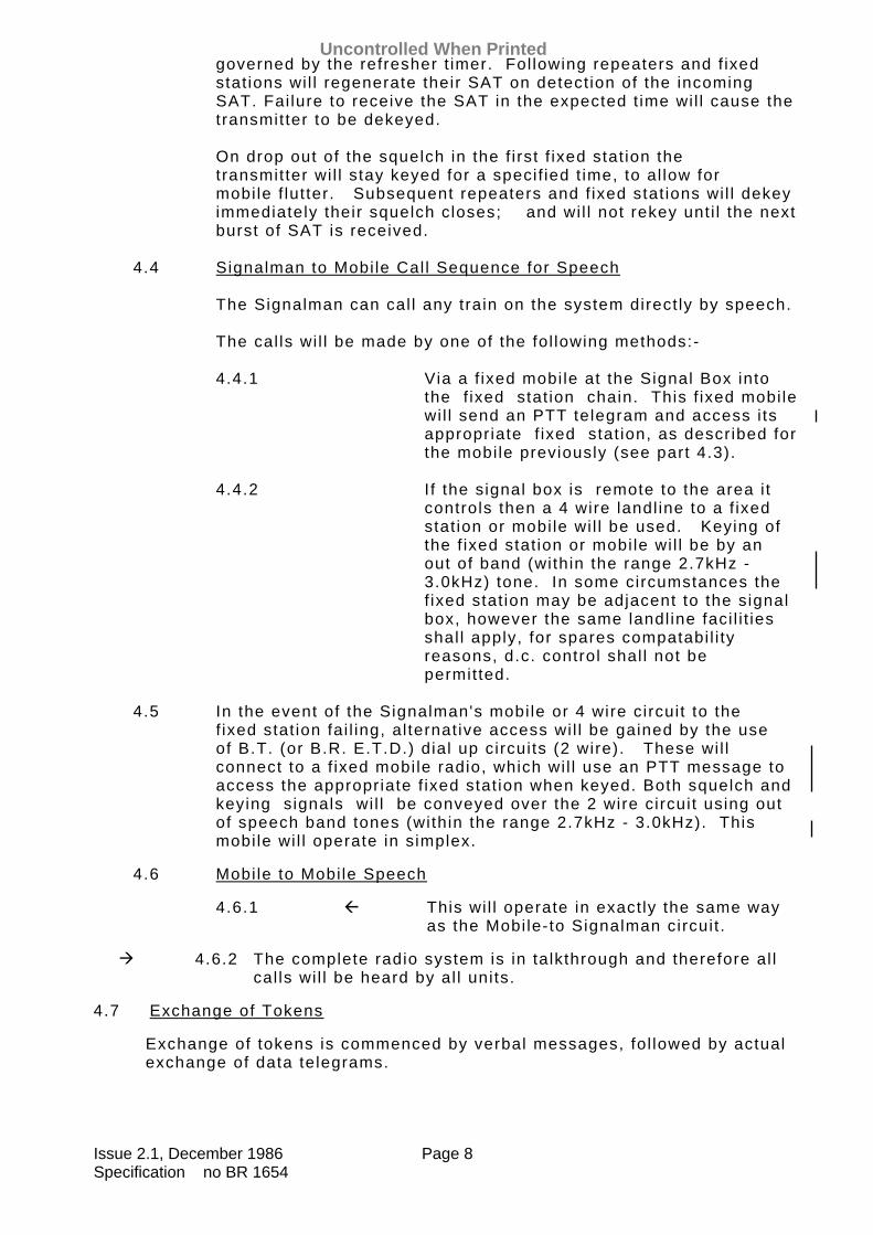
4.4 Signalman to Mobi le Cal l Sequence for Speech The Signalman can cal l any train on the system direct ly by speech. The cal ls wi l l be made by one of the fol lowing methods:-
4.4.1 Via a f ixed mobi le at the Signal Box into the f ixed stat ion chain. This f ixed mobi le wi l l send an PTT telegram and access i ts appropriate f ixed stat ion, as described for the mobi le previously (see part 4.3).
4.4.2 I f the signal box is remote to the area i t
controls then a 4 wire landl ine to a f ixed stat ion or mobi le wi l l be used. Keying of the f ixed stat ion or mobi le wi l l be by an out of band (within the range 2.7kHz - 3.0kHz) tone. In some circumstances the f ixed stat ion may be adjacent to the signal box, however the same landl ine faci l i t ies shal l apply, for spares compatabi l i ty reasons, d.c. control shal l not be permitted.
4.5 In the event of the Signalman's mobi le or 4 wire circuit to the
f ixed stat ion fai l ing, al ternat ive access wi l l be gained by the use of B.T. (or B.R. E.T.D.) dial up circuits (2 wire). These wi l l connect to a f ixed mobi le radio, which wi l l use an PTT message to access the appropriate f ixed stat ion when keyed. Both squelch and keying signals wi l l be conveyed over the 2 wire circuit using out of speech band tones (within the range 2.7kHz - 3.0kHz). This mobi le wi l l operate in simplex.
4.6 Mobi le to Mobi le Speech
4.6.1 This wi l l operate in exact ly the same way as the Mobi le-to Signalman circuit .
4.6.2 The complete radio system is in talkthrough and therefore al l cal ls wi l l be heard by al l units.
4.7 Exchange of Tokens
Exchange of tokens is commenced by verbal messages, fol lowed by actual exchange of data telegrams.
Uncontrolled When Printed

Issue 2.1, December 1986 Page 9 Specification no BR 1654
Data messages are 1200 Bits per Second F.F.S.K., in accordance with MPT 1317.
The i n i t i a l da ta message i s sen t f r om the So l i d S ta te I n t e r l ock i ng
(SS I ) . I t r equ i r es a sque l ch s i gna l ( f r om the S igna lman ' s r ad io i n t e r f ace ) t o ensu re t he sys tem i s f r ee , t hen i n i t i a t es a key i ns t r uc t i on t o t he r ad io i n t e r f ace . Th i s key i ns t r uc t i on w i l l cause an PTT t e l eg ram ( i f r ad i o f i t t ed ) o r key s i gna l t o l i ne ( i f a 4 w i r e connec t i on ) t o be sen t , a f t e r wh i ch t he t r ansm i t c l ock (TX CLK) w i l l be sen t t o t he SS I i n t e r f ace . The SS I w i l l now ou tpu t da ta t o a l l mob i l es . On rece ip t o f t h i s t e l eg ram the app rop r i a t e mob i l e w i l l respond wi th a data handshake and fo l lowing the handshake the SSI wi l l t r ansm i t t he t oken .
The t iming diagrams are given in Appendix A & B. The SSI interface is
t o d raw ing No . ELS-A1 -3311 i s sue D da ted 15 /8 /84 . The recovery o f the token f rom the t ra in cons is ts o f a da ta handshake
on ly , aga in o r ig ina ted by the SSI . I f no response i s rece ived f rom the t ra in the SSI w i l l make 5 a t tempts
t o t r ansm i t a t oken . 4.8 F r i nge S igna l Boxes , Leve l C ross i ng Mon i t o r i ng , Po in t Con t ro l , e t c .
(Anc i l l a r y da ta , see pa r t 5 . 4 .2 . ) . 4.8.1 Data exchange for control of fr inge signal l ing information,
monitor ing of level crossing alarms and point control is not necessari ly preceded by speech, the f i rst message may be in i t ia ted by e i ther end . Data i s 600 b i ts per second (FSK) with tone frequencies of 1060Hz and 1260Hz.
4.8.2 The radio interface is at audio with squelch and key condit ions
on separate l ines.
Uncontrolled When Printed

Issue 2.1, December 1986 Page 10 Specification no BR 1654
5. SYSTEM DETAIL
5.1.1
This sect ion contains the fol lowing detai led Specif icat ions:-
System Timing.
Fixed Stat ions, Fixed Mobi les, Cross Channel Repeaters. Interfaces. Signalman's Control Panel. Telephone. Alarms. Data and Tones present on system and f i l ter ing requirements. Levels of Signals present on system.
5.1.2.
Al l mobi le and portable radios requested within the schedule must conform to BR Specif icat ion 1609.
5.2. Timing Al l t imings quoted shal l be to an accuracy of+5%. The l imits
indicated below are to be techmician adjustable in the f ield. 5.2.1. Refresher Timer Al l f ixed stat ions shal l be f i t ted with this t imer. When an PTT telegram is decoded by the receiver, the Refresher
Timer is reset, and a burst of SAT is transmitted by the f ixed stat ion. The Refresher Timer shal l be set at 5 seconds, but capable of variat ion between 2 and 10 seconds, and wi l l key the SAT generator at 5 seconds intervals unt i l the receiver squelch is closed (see part 5.2.3.).
5.2.2. SAT Timer The Super Audio Tone Burst Timer shal l be f i t ted to al l f ixed
stat ions and repeaters. The SAT t imer shal l be set to give 100ms Bursts of SAT (see part 5.7) but shal l be capable of variat ion between 30ms & 300ms.
The SAT shal l be detected within a minimum of 20ms and a
maximum of 30ms at al l f ixed stat ions and repeaters. 5.2.3 Anti-Flutter Timer Should the Mobi le which sent the PTT telegram drop out due to
signal f lut ter, the f ixed stat ion that acknowledged i t shal l be capable of holding i t 's transmitter key l ine up for 20ms, the
Uncontrolled When Printed
Issue 2.1, December 1986 Page 11 Specification no BR 1654
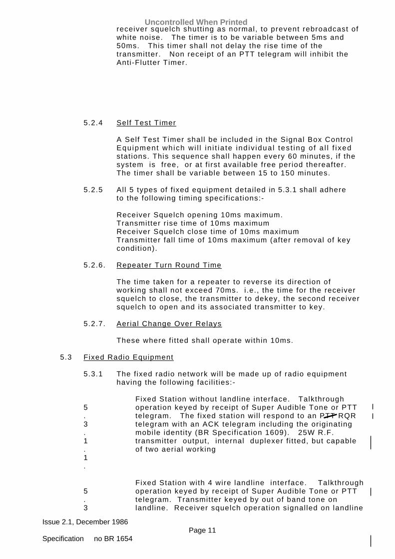
receiver squelch shutt ing as normal, to prevent rebroadcast of white noise. The t imer is to be variable between 5ms and 50ms. This t imer shal l not delay the r ise t ime of the transmitter. Non receipt of an PTT telegram wil l inhibi t the Anti-Flutter Timer.
5.2.4 Self Test Timer A Self Test Timer shal l be included in the Signal Box Control
Equ ipment wh ich w i l l i n i t ia te ind iv idua l tes t ing o f a l l f i xed stat ions. This sequence shal l happen every 60 minutes, i f the system is free, or at f i rst avai lable free period thereafter. The t imer shal l be variable between 15 to 150 minutes.
5.2.5 Al l 5 types of f ixed equipment detai led in 5.3.1 shall adhere
to the fol lowing t iming specif icat ions:- Receiver Squelch opening 10ms maximum.
Transmitter r ise t ime of 10ms maximum Receiver Squelch close t ime of 10ms maximum Transmitter fal l t ime of 10ms maximum (after removal of key condit ion).
5.2.6. Repeater Turn Round Time The t ime taken for a repeater to reverse i ts direct ion of
working shal l not exceed 70ms. i .e. , the t ime for the receiver squelch to close, the transmitter to dekey, the second receiver squelch to open and i ts associated transmitter to key.
5.2.7. Aerial Change Over Relays These where f i t ted shal l operate within 10ms. 5.3 Fixed Radio Equipment 5.3.1 The f ixed radio network wi l l be made up of radio equipment
having the fol lowing faci l i t ies:-
5.3.1.1.
Fixed Stat ion without landl ine interface. Talkthrough operat ion keyed by receipt of Super Audible Tone or PTT telegram. The f ixed stat ion wi l l respond to an PTT RQR telegram with an ACK telegram including the or iginat ing mobi le ident i ty (BR Specif icat ion 1609). 25W R.F. transmitter output, internal duplexer f i t ted, but capable of two aerial working
5.3
Fixed Stat ion with 4 wire landl ine interface. Talkthrough operat ion keyed by receipt of Super Audible Tone or PTT telegram. Transmitter keyed by out of band tone on landl ine. Receiver squelch operat ion signal led on landl ine
Uncontrolled When Printed

Issue 2.1, December 1986 Page 12 Specification no BR 1654
.1.2.
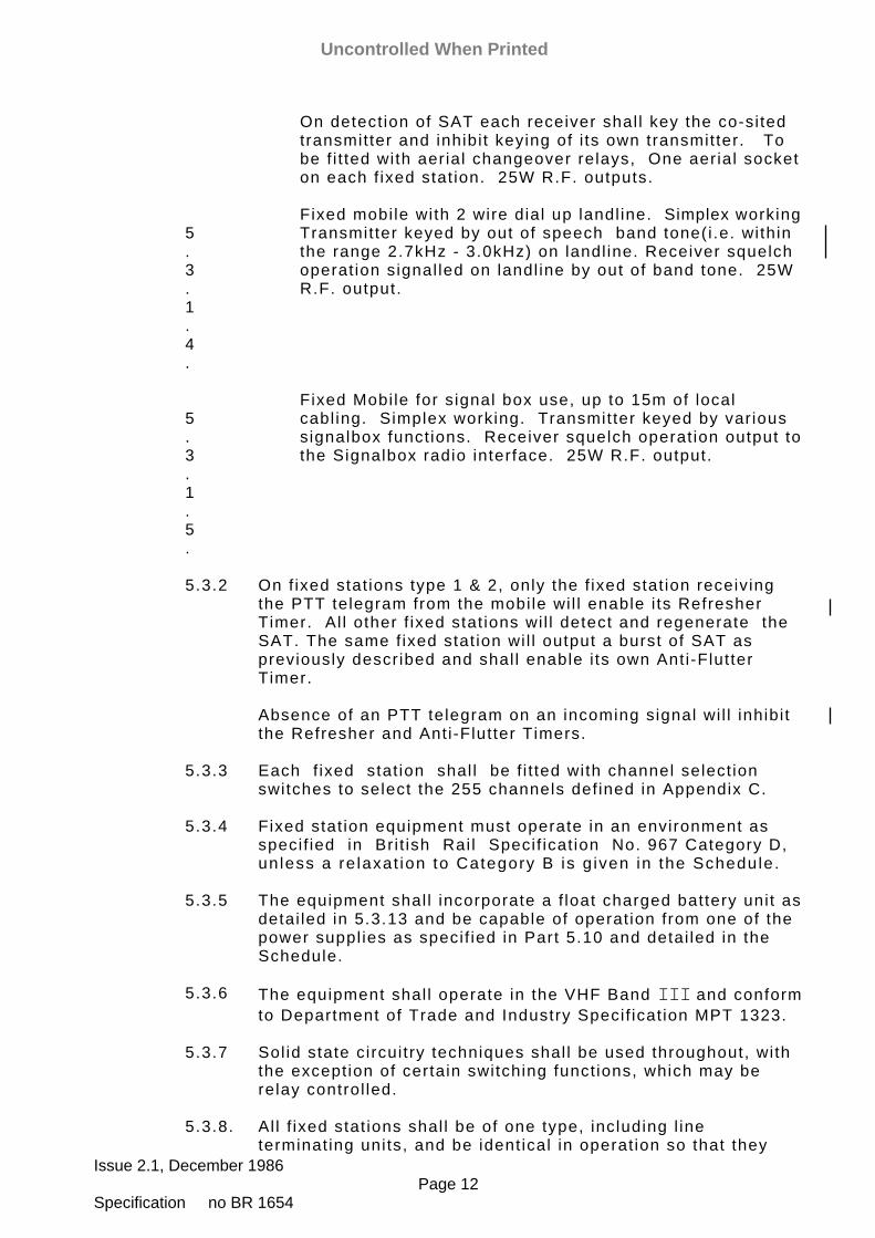
by out of band tone. The f ixed stat ion wi l l respond to an RQR telegram with an ACK telegram including the or iginat ing mobi le ident i ty (BR Specif icat ion 1609).25W R.F. output, internal duplexer f i t ted, but capable of two aerial working.
5.3.1.3.
Cross Channel Repeater. Made up of two ident ical f ixed stat ions operat ing on mobi le frequencies. No landl ine interface.
Uncontrolled When Printed
Issue 2.1, December 1986 Page 12 Specification no BR 1654
On detect ion of SAT each receiver shal l key the co-si ted transmitter and inhibi t keying of i ts own transmitter. To be f i t ted with aerial changeover relays, One aerial socket on each f ixed stat ion. 25W R.F. outputs.
5.3.1.4.
Fixed mobi le with 2 wire dial up landl ine. Simplex working Transmitter keyed by out of speech band tone(i .e. within the range 2.7kHz - 3.0kHz) on landl ine. Receiver squelch operat ion signal led on landl ine by out of band tone. 25W R.F. output.
5.3.1.5.
Fixed Mobi le for signal box use, up to 15m of local cabl ing. Simplex working. Transmitter keyed by various signalbox funct ions. Receiver squelch operat ion output to the Signalbox radio interface. 25W R.F. output.
5.3.2 On f ixed stat ions type 1 & 2, only the f ixed stat ion receiving
the PTT telegram from the mobi le wi l l enable i ts Refresher Timer. Al l other f ixed stat ions wi l l detect and regenerate the SAT. The same f ixed stat ion wi l l output a burst of SAT as previously described and shal l enable i ts own Anti-Flutter Timer.
Absence of an PTT telegram on an incoming signal wi l l inhibi t
the Refresher and Anti-Flutter Timers. 5.3.3 Each f ixed stat ion shal l be f i t ted with channel select ion
switches to select the 255 channels def ined in Appendix C. 5.3.4 Fixed stat ion equipment must operate in an environment as
specif ied in Bri t ish Rai l Specif icat ion No. 967 Category D, un less a re laxat ion to Category B is g iven in the Schedule.
5.3.5 The equipment shal l incorporate a f loat charged battery unit as
detai led in 5.3.13 and be capable of operat ion from one of the power suppl ies as specif ied in Part 5.10 and detai led in the Schedule.
5.3.6 The equipment shal l operate in the VHF Band III and conform
to Department of Trade and Industry Specif icat ion MPT 1323. 5.3.7 Sol id state circuitry techniques shal l be used throughout, with
the exception of certain switching funct ions, which may be relay control led.
5.3.8. Al l f ixed stat ions shal l be of one type, including l ine
terminat ing units, and be ident ical in operat ion so that they
Uncontrolled When Printed
Issue 2.1, December 1986 Page 13 Specification no BR 1654
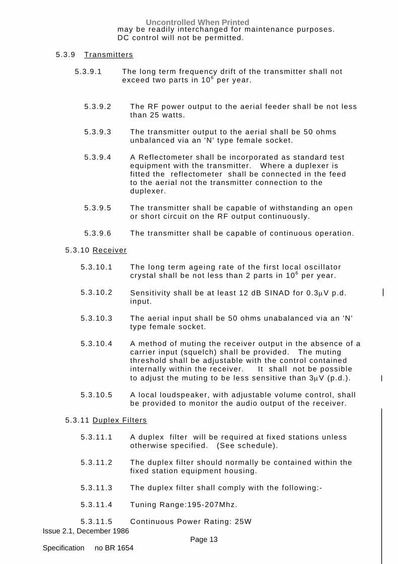
may be readi ly interchanged for maintenance purposes. DC control wi l l not be permitted.
5.3.9 Transmitters 5.3.9.1 The long term frequency dri f t of the transmitter shal l not
exceed two parts in 106 per year.
5.3.9.2 The RF power output to the aerial feeder shal l be not less
than 25 watts. 5.3.9.3 The transmitter output to the aerial shal l be 50 ohms
unbalanced via an 'N' type female socket. 5.3.9.4 A Reflectometer shal l be incorporated as standard test
equipment with the transmitter. Where a duplexer is f i t ted the ref lectometer shal l be connected in the feed to the aerial not the transmitter connect ion to the duplexer.
5.3.9.5 The transmitter shal l be capable of withstanding an open
or short circuit on the RF output cont inuously. 5.3.9.6 The transmitter shal l be capable of cont inuous operat ion. 5.3.10 Receiver 5.3.10.1 The long term ageing rate of the f i rs t loca l osc i l la tor
crystal shal l be not less than 2 parts in 106 per year. 5.3.10.2 Sensit iv i ty shal l be at least 12 dB SINAD for 0.3µV p.d.
input. 5.3.10.3 The aerial input shal l be 50 ohms unabalanced via an 'N'
type female socket. 5.3.10.4 A method of muting the receiver output in the absence of a
carr ier input (squelch) shal l be provided. The muting threshold shal l be adjustable with the control contained internal ly within the receiver. I t shal l not be possible to adjust the muting to be less sensit ive than 3µV (p.d.).
5.3.10.5 A local loudspeaker, with adjustable volume control , shal l
be provided to monitor the audio output of the receiver. 5.3.11 Duplex Fi l ters 5.3.11.1 A duplex f i l ter wi l l be required at f ixed stat ions unless
otherwise specif ied. (See schedule). 5.3.11.2 The duplex f i l ter should normally be contained within the
f ixed stat ion equipment housing. 5.3.11.3 The duplex f i l ter shal l comply with the fol lowing:- 5.3.11.4 Tuning Range:195-207Mhz. 5.3.11.5 Continuous Power Rating: 25W
Uncontrolled When Printed
Issue 2.1, December 1986 Page 14 Specification no BR 1654
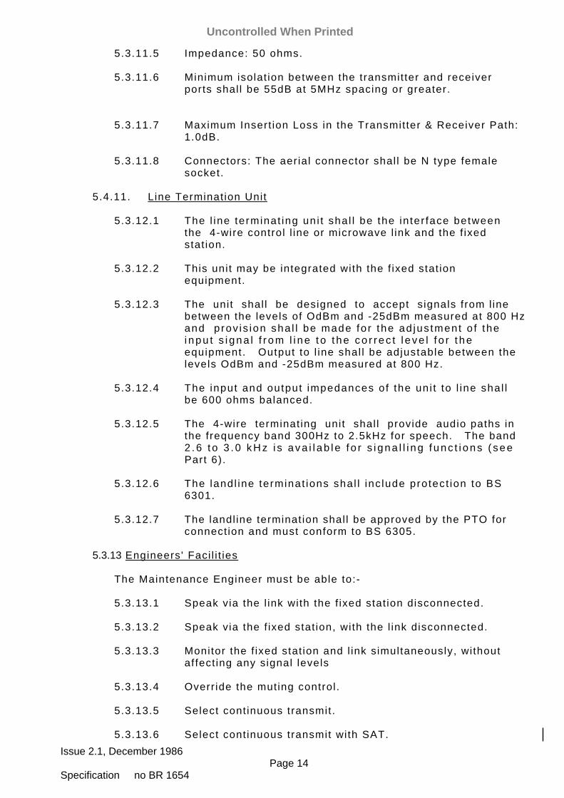
5.3.11.5 Impedance: 50 ohms. 5.3.11.6 Minimum isolat ion between the transmitter and receiver
ports shal l be 55dB at 5MHz spacing or greater. 5.3.11.7 Maximum Insert ion Loss in the Transmitter & Receiver Path:
1.0dB. 5.3.11.8 Connectors: The aerial connector shal l be N type female
socket. 5.4.11. Line Terminat ion Unit 5.3.12.1 The l ine terminat ing un i t shal l be the in ter face between
the 4-wire control l ine or microwave l ink and the f ixed stat ion.
5.3.12.2 This unit may be integrated with the f ixed stat ion
equipment. 5.3.12.3 The unit shal l be designed to accept s ignals from l ine
between the levels of OdBm and -25dBm measured at 800 Hz and p rov is ion sha l l be made fo r the ad jus tment o f the i npu t s i gna l f r om l i ne t o t he co r rec t l e ve l f o r t he equipment. Output to l ine shal l be adjustable between the levels OdBm and -25dBm measured at 800 Hz.
5.3.12.4 The input and output impedances of the un i t to l ine shal l
be 600 ohms balanced. 5.3.12.5 The 4-wire terminat ing unit shal l provide audio paths in
the frequency band 300Hz to 2.5kHz for speech. The band 2 .6 t o 3 .0 kHz i s ava i l ab l e f o r s i gna l l i ng f unc t i ons ( see Part 6).
5.3.12.6 The landl ine terminat ions shal l inc lude protect ion to BS
6301. 5.3.12.7 The landl ine terminat ion shal l be approved by the PTO for
connect ion and must conform to BS 6305. 5.3.13 Engineers' Faci l i t ies The Maintenance Engineer must be able to:- 5.3.13.1 Speak via the l ink with the f ixed stat ion disconnected. 5.3.13.2 Speak via the f ixed stat ion, with the l ink disconnected. 5.3.13.3 Monitor the f ixed stat ion and l ink simultaneously, without
affect ing any signal levels 5.3.13.4 Overr ide the muting control . 5.3.13.5 Select cont inuous transmit. 5.3.13.6 Select cont inuous transmit with SAT.
Uncontrolled When Printed

Issue 2.1, December 1986 Page 15 Specification no BR 1654
5.3.13.7 Select talk-through by means of a locking key.
Uncontrolled When Printed
Issue 2.1, December 1986 Page 16 Specification no BR 1654
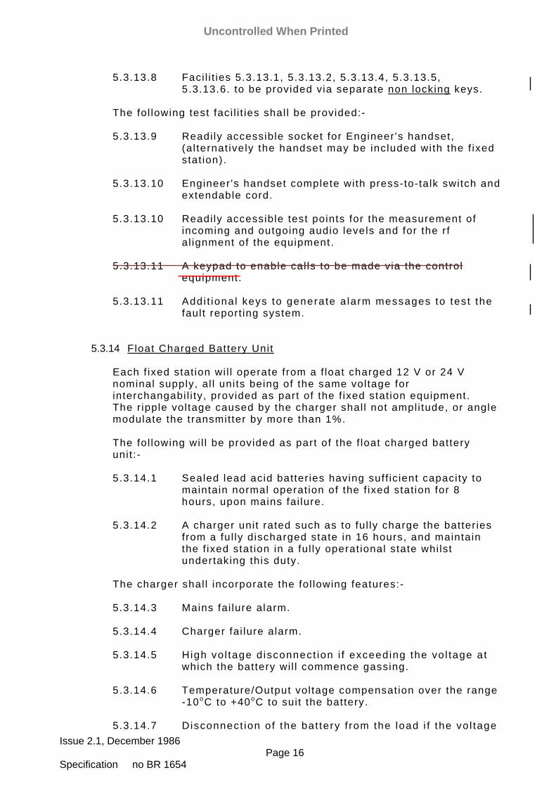
5.3.13.8 Faci l i t ies 5.3.13.1, 5.3.13.2, 5.3.13.4, 5.3.13.5, 5.3.13.6. to be provided via separate non locking keys.
The fol lowing test faci l i t ies shal l be provided:- 5.3.13.9 Readi ly accessible socket for Engineer 's handset,
(al ternat ively the handset may be included with the f ixed stat ion).
5.3.13.10 Engineer 's handset complete with press-to-talk switch and
extendable cord. 5.3.13.10 Readi ly accessible test points for the measurement of
incoming and outgoing audio levels and for the rf al ignment of the equipment.
5.3.13.11 A keypad to enable cal ls to be made via the control
equipment. 5.3.13.11 Addi t ional keys to generate a larm messages to test the
fault report ing system. 5.3.14 Float Charged Battery Unit Each f ixed stat ion wi l l operate from a f loat charged 12 V or 24 V
nominal supply, al l units being of the same voltage for interchangabi l i ty, provided as part of the f ixed stat ion equipment. The r ipple voltage caused by the charger shal l not ampli tude, or angle
modulate the transmitter by more than 1%. The fol lowing wi l l be provided as part of the f loat charged battery
unit :- 5.3.14.1 Sealed lead acid batter ies having suff ic ient capacity to
maintain normal operat ion of the f ixed stat ion for 8 hours, upon mains fai lure.
5.3.14.2 A charger unit rated such as to ful ly charge the batter ies
from a ful ly discharged state in 16 hours, and maintain the f ixed stat ion in a ful ly operat ional state whi lst undertaking this duty.
The charger shal l incorporate the fol lowing features:- 5.3.14.3 Mains fai lure alarm. 5.3.14.4 Charger fai lure alarm. 5.3.14.5 High vo l tage d isconnect ion i f exceeding the vo l tage at
which the battery wi l l commence gassing. 5.3.14.6 Temperature/Output voltage compensation over the range
-10oC to +40oC to suit the battery. 5.3.14.7 Disconnect ion of the bat tery f rom the load i f the vo l tage
Uncontrolled When Printed

Issue 2.1, December 1986 Page 17 Specification no BR 1654
fal ls below that at which damage wi l l occur. 5.3.14.8 The maximum ripple appl ied to the battery during charging
wi l l be 100 mV per cel l . 5.3.14.9 Al l l ine terminals shal l be shrouded in accordance with
health and safety requirements. 5.3.14.10 Plug and socket connect ions shal l be prov ided for inputs
and outputs to a design approved by the Engineer. 5.3.13 Data messages shal l be generated by each i tem of f ixed radio
equipment to indicate:- 5.3.15.1 Mains fai lure. 5.3.15.2 Charger fai lure. 5.3.15.3 Intruder alarm. 5.3.15.4 Restorat ion of alarms. 5.3.15.5 Reply to l ine test telegram. 5.3.15.6 ) 5.3.15.7 ) Spare, to be def ined. 5.3.15.8 ) 5.4 Interfaces Th is sect ion deta i ls the var ious in ter faces requi red at the Signalbox and
at remote locat ions which have auxi lary data faci l i t ies. 5.4.1 Sol id State Inter locking Interface The Signalman's radio faci l i ty shal l interfact to the SSI. BR
wi l l supply as part of the SSI balanced inputs and outputs to Drawings ELS-A4-3310 and ELS -A1-3311. The radio contractor shal l provide suitable circuits to accept and supply signals to these inputs and outputs and the assoc iated cabl ing. The maximum seperat ion between the SSI and the radio faci l i ty wi l l be 50 metres.
5.4.2 Auxi lary Data Interface The s igna lmans rad io fac i l i t y w i l l i n te r face to a spec i f ied
number o f aux i la ry da ta un i ts . A t remote loca t ions an iden t ica l in te r face w i l l be requ i red to work to f r inge S igna lboxes , Leve l Cross ing Mon i to r ing Un i ts and Po in t con t ro ls . Deta i l s o f the type o f inpu t and ou tpu t connec t ions requ i red a re g iven in Append ix C. The rad io con t rac to r sha l l p rov ide su i tab le c i rcu i ts to accept and supp ly s igna ls to these inpu ts and ou tpu ts and the assoc ia ted cab l ing . The max imum separa t ion be tween the aux i la ry da ta un i t and the rad io facility will be 50 met res .
5.4.3 Telephone interfaces
Uncontrolled When Printed

Issue 2.1, December 1986 Page 18 Specification no BR 1654
5.4.3.1. The S igna lman ' s r ad io f ac i l i t y sha l l i n t e r f ace t o a BR ETD o r BT STD te l ephone i ns t r umen t . To ach ieve t h i s a s t anda rd LJU con fo rm ing t o BS6312 sha l l be p rov i ded .
5.4.3.2 The S igna lman ' s r ad i o f ac i l i t y sha l l i n t e r f ace t o one o r mo re (as spec i f i ed i n t he schedu le ) BR ETD o r BT STD te l ephone l i nes . To ach ieve t h i s s t anda rd Jacks sha l l be p rov i ded .
5.4.3.3
A two pos i t i on key sw i t ch sha l l be p rov i ded t o a l l ow each t e l ephone l i ne t o be connec ted t o t he i ns t r umen t o r t he r ad io f ac i l i t y . When connec ted t o t he i ns t r umen t f u l l t e l ephone f ac i l i t i e s w i l l be ava i l ab l e . When connec ted t o t he r ad i o f ac i l i t y a l l da ta and aud io sen t t o and rece i ved f r o m t h e r a d i o s y s t e m w i l l s i m i l a r l y b e s e n t t o a n d rece i ved f r om the t e l ephone c i r cu i t . I f t he c i r cu i t i s s p e c i f i e d a s a d i a l u p c i r c u i t f o r r e m o t e c o n t r o l o f t h e r ad io sys tem con t ro l t ones as spec i f i ed i n 5 .7 .2 .2 w i l l be sen t t o o r r ece i ved on t h i s l i ne .
5.5 Signalmans Radio Panel
The Signalmans radio panel shal l be desk mounted and have the fol lowing operator controls, faci l i t ies and indicat ions:-
5.5.1 An integral loudspeaker with volume control to al low monitor ing of the radio system, this shal l be switched, not cont inously variable. When the handset is in use (See part 5.5.2) muting of the loudspeaker shal l be opt ional ly avai lable.
5.5.2
A microphone with press to talk switch connected through an extensible cord and locking plug and socket. The socket wi l l al low a handset with microphone and earpiece to be connected i f required.
5.5.3. Telephone connect key for the dial up circuits, i f specif ied in
the schedule, with 3 posit ions:- In posit ion 1 incoming telephone cal ls wi l l be indicated
by an audible alert In posit ion 2 Incoming telephone cal ls can be answered by
the signalman and outgoing cal ls can be made, using the seperate telephone instrument.
In pos i t ion 3 the c i rcu i t w i l l be connected in para l le l with the normal radio input/output.
5.5.4. Radio System Test key to ini t iate self test of radio network
and associated alarm indicator (See part 5.6) 5.5.5 Radio interface transmit indicator 5.5.6. Channel switch with an indicat ion of the channel selected.
(Only appl icable to Signal Box f i t ted with Fixed Mobi le.) 5.5.7. The Signalman's Radio Panel shal l operate in the enviromental
condit ions specif ied in B.R. Specif icat ion 967 Category C.
Uncontrolled When Printed

Issue 2.1, December 1986 Page 19 Specification no BR 1654
5.6 Alarms and Test Faci l i t ies 5.6.1 The fol lowing alarm condit ions shal l be ident i f ied by means of
data messages generated at each f ixed radio stat ion.
5.6.1.1.
Mains Fai lure
5.6.1.2
Charger fai lure
5.6.1.3
Intruder alarms
5.6.1.4
Restorat ion of alarms
5.6.1.5
Reply to f ixed stat ion test telegram (See part 5.6.3)
5.6.1.
Three spares to be def ined
Uncontrolled When Printed

Issue 2.1, December 1986 Page 20 Specification no BR 1654
6 5.6.2 Any fai lures wi l l be indicated individual ly on a technicians
alarm panel at the signalbox and as a single indicat ion on the signalmans panel.
5.6.3 Fixed Stat ion Test Telegram.
5.6.3.1.
Fac i l i t i es sha l l be p rov ided to ind iv idua l l y tes t each f ixed stat ion and repeater from the Technicians alarm panel (See 5.2.4). I f received at the f ixed stat ion this wi l l cause a data telegram reply giving the f ixed stat ion ident i ty. Fai lure to receive the reply wi l l give an alarm indicat ion.
5.6.3.2.
A sequence of test telegrams addressing al l f ixed stat ions and repeaters wi l l be sent automatical ly every hour and when a test is ini t iated by the Signalman's alarm key.
5.6.3.3
The test system shal l be des igned such that test te legrams can be routed in the same way as speech and data by any individual route into the radio system.
5.7. Data and Tones present in the system This sect ion detai ls the data and tones present on the system and the
f i l ter ing requirements to remove these from audio circuits. 5.7.1 Data 5.7.1.1. RETB control data:- 1200 bit /s FFSK to MPT 1317. This may
contain any blocks of ASCII characters. This is not to be f i l tered at the Signalman's panel. To be broadcast at 70% peak deviat ion ( + 1.75kHz) for both tones.
Uncontrolled When Printed
Issue 2.1, December 1986 Page 21 Specification no BR 1654
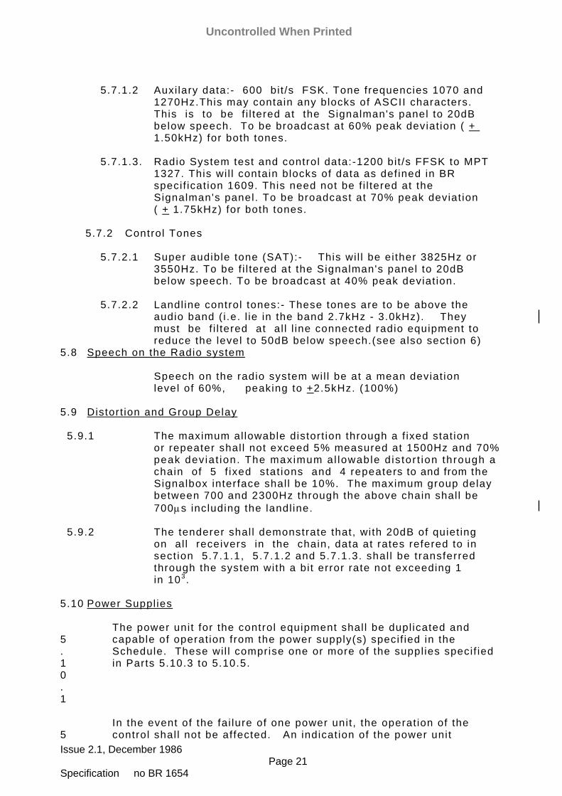
5.7.1.2 Auxi lary data:- 600 bi t /s FSK. Tone frequencies 1070 and
1270Hz.This may contain any blocks of ASCII characters. This is to be f i l tered at the Signalman's panel to 20dB below speech. To be broadcast at 60% peak deviat ion ( + 1.50kHz) for both tones.
5.7.1.3. Radio System test and control data:-1200 bit /s FFSK to MPT
1327. This wi l l contain blocks of data as def ined in BR specif icat ion 1609. This need not be f i l tered at the Signalman's panel. To be broadcast at 70% peak deviat ion ( + 1.75kHz) for both tones.
5.7.2 Control Tones 5.7.2.1 Super audible tone (SAT):- This wi l l be ei ther 3825Hz or
3550Hz. To be f i l tered at the Signalman's panel to 20dB below speech. To be broadcast at 40% peak deviat ion.
5.7.2.2 Landl ine control tones:- These tones are to be above the
audio band ( i .e. l ie in the band 2.7kHz - 3.0kHz). They must be f i l tered at al l l ine connected radio equipment to reduce the level to 50dB below speech.(see also sect ion 6)
5.8 Speech on the Radio system Speech on the radio system wil l be at a mean deviat ion
level of 60%, peaking to +2.5kHz. (100%) 5.9 Distort ion and Group Delay 5.9.1 The maximum al lowable distort ion through a f ixed stat ion
or repeater shal l not exceed 5% measured at 1500Hz and 70% peak dev iat ion. The maximum al lowable d is tor t ion through a chain of 5 f ixed stat ions and 4 repeaters to and from the Signalbox interface shal l be 10%. The maximum group delay between 700 and 2300Hz through the above chain shal l be 700µs including the landl ine.
5.9.2 The tenderer shal l demonstrate that, with 20dB of quiet ing
on al l receivers in the chain, data at rates refered to in sect ion 5.7.1.1, 5.7.1.2 and 5.7.1.3. shal l be t ransferred through the system with a bi t error rate not exceeding 1 in 103.
5.10 Power Suppl ies 5.10.1
The power unit for the control equipment shal l be dupl icated and capable of operat ion from the power supply(s) specif ied in the Schedule. These wi l l comprise one or more of the suppl ies specif ied in Parts 5.10.3 to 5.10.5.
5
In the event of the fai lure of one power unit , the operat ion of the control shal l not be affected. An indicat ion of the power unit
Uncontrolled When Printed

Issue 2.1, December 1986 Page 22 Specification no BR 1654
.10.2
fai lure shal l also be given and a fault report generated. Uncontrolled When Printed
Issue 2.1, December 1986 Page 23 Specification no BR 1654
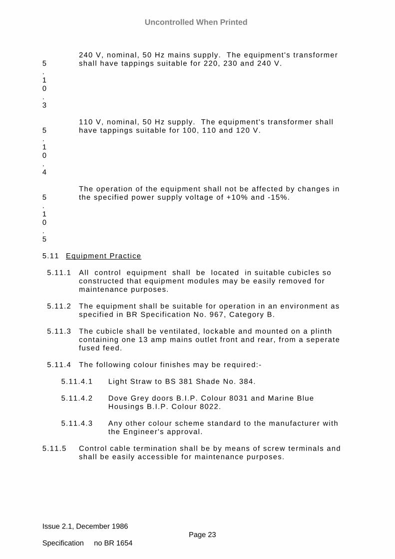
5.10.3
240 V, nominal, 50 Hz mains supply. The equipment 's transformer shal l have tappings suitable for 220, 230 and 240 V.
5.10.4
110 V, nominal, 50 Hz supply. The equipment 's transformer shal l have tappings suitable for 100, 110 and 120 V.
5.10.5
The operat ion of the equipment shal l not be affected by changes in the specif ied power supply voltage of +10% and -15%.
5.11 Equipment Pract ice 5.11.1 Al l control equipment shal l be located in suitable cubicles so
constructed that equipment modules may be easi ly removed for maintenance purposes.
5.11.2 The equipment shal l be suitable for operat ion in an environment as
specif ied in BR Specif icat ion No. 967, Category B. 5.11.3 The cubicle shal l be vent i lated, lockable and mounted on a pl inth
containing one 13 amp mains out let front and rear, from a seperate fused feed.
5.11.4 The fol lowing colour f inishes may be required:- 5.11.4.1 Light Straw to BS 381 Shade No. 384. 5.11.4.2 Dove Grey doors B.I .P. Colour 8031 and Marine Blue Housings B.I .P. Colour 8022. 5.11.4.3 Any other colour scheme standard to the manufacturer with
the Engineer 's approval. 5.11.5 Control cable terminat ion shal l be by means of screw terminals and
shal l be easi ly accessible for maintenance purposes.
Uncontrolled When Printed
Issue 2.1, December 1986 Page 24 Specification no BR 1654
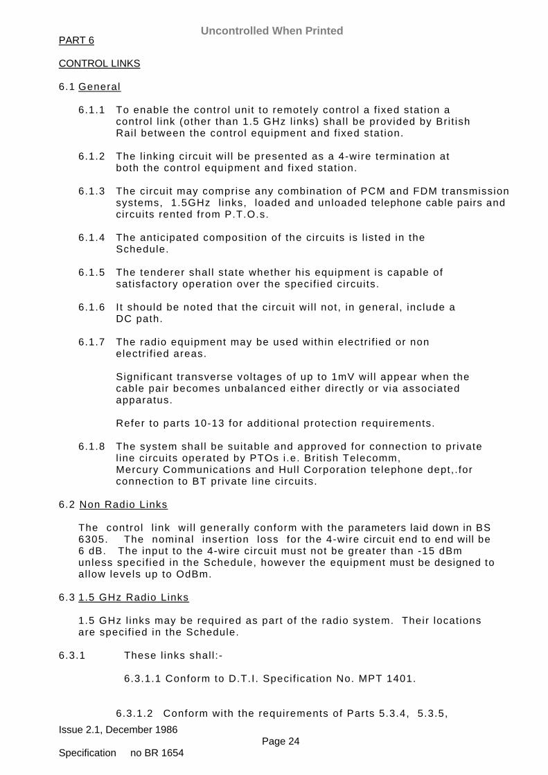
PART 6 CONTROL LINKS 6.1 General 6.1.1 To enable the control unit to remotely control a f ixed stat ion a
control l ink (other than 1.5 GHz l inks) shal l be provided by Bri t ish Rai l between the control equipment and f ixed stat ion.
6.1.2 The l inking circuit wi l l be presented as a 4-wire terminat ion at
both the control equipment and f ixed stat ion. 6.1.3 The circuit may comprise any combinat ion of PCM and FDM transmission
systems, 1.5GHz l inks, loaded and unloaded telephone cable pairs and circuits rented from P.T.O.s.
6.1.4 The ant ic ipated composit ion of the circuits is l isted in the
Schedule. 6.1.5 The tenderer shal l state whether his equipment is capable of
sat isfactory operat ion over the specif ied circuits. 6.1.6 I t should be noted that the circuit wi l l not, in general, include a
DC path. 6.1.7 The radio equipment may be used within electr i f ied or non
electr i f ied areas. Signif icant transverse voltages of up to 1mV wil l appear when the
cable pair becomes unbalanced either direct ly or via associated apparatus.
Refer to parts 10-13 for addit ional protect ion requirements. 6.1.8 The system shal l be suitable and approved for connect ion to pr ivate
l ine circuits operated by PTOs i .e. Bri t ish Telecomm, Mercury Communicat ions and Hul l Corporat ion telephone dept, . for connect ion to BT private l ine circuits.
6.2 Non Radio Links The control l ink wi l l general ly conform with the parameters laid down in BS
6305. The nominal insert ion loss for the 4-wire circuit end to end will be 6 dB. The input to the 4-wire circuit must not be greater than -15 dBm unless specif ied in the Schedule, however the equipment must be designed to
al low levels up to OdBm. 6.3 1.5 GHz Radio Links 1.5 GHz l inks may be required as part of the radio system. Their locat ions
are specif ied in the Schedule. 6.3.1 These l inks shal l : - 6.3.1.1 Conform to D.T.I . Specif icat ion No. MPT 1401. 6.3.1.2 Conform with the requirements of Parts 5.3.4, 5.3.5,
Uncontrolled When Printed

Issue 2.1, December 1986 Page 25 Specification no BR 1654
5.3.7, 5.3.8, 5.3.9, 5.3.10.1, 5.3.10.3, 5.3.10.5. 6.3.1.3 Be ful ly compatible with f ixed stat ions as def ined in
Part 5.
Uncontrolled When Printed
Issue 2.1, December 1986 Page 26 Specification no BR 1654
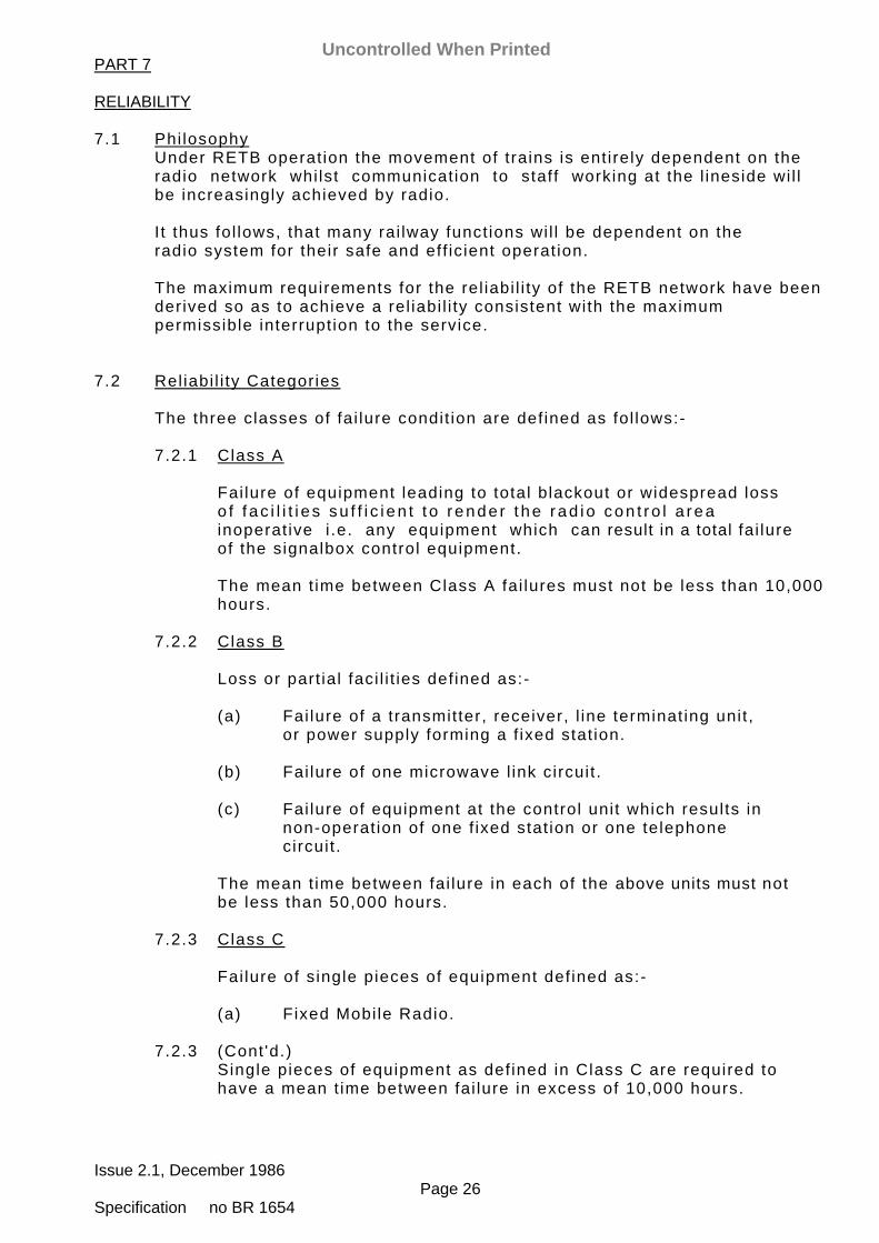
PART 7 RELIABILITY 7.1 Phi losophy Under RETB operat ion the movement of trains is ent irely dependent on the
radio network whi lst communicat ion to staff working at the l ineside wi l l be increasingly achieved by radio.
I t thus fol lows, that many rai lway funct ions wi l l be dependent on the
radio system for their safe and eff ic ient operat ion. The maximum requirements for the rel iabi l i ty of the RETB network have been
derived so as to achieve a rel iabi l i ty consistent with the maximum permissible interrupt ion to the service.
7.2 Rel iabi l i ty Categories The three classes of fai lure condit ion are def ined as fol lows:- 7.2.1 Class A Fai lure of equipment leading to total blackout or widespread loss
o f f ac i l i t i e s su f f i c i en t t o r ende r t he r ad io con t ro l a rea inoperat ive i .e. any equipment which can result in a total fai lure of the signalbox control equipment.
The mean t ime between Class A fai lures must not be less than 10,000
hours. 7.2.2 Class B Loss or part ial faci l i t ies def ined as:- (a) Fai lure of a transmitter, receiver, l ine terminat ing unit ,
or power supply forming a f ixed stat ion. (b) Fai lure of one microwave l ink circuit . (c) Fai lure of equipment at the control unit which results in
non-operat ion of one f ixed stat ion or one telephone circuit .
The mean t ime between fai lure in each of the above units must not
be less than 50,000 hours. 7.2.3 Class C Fai lure of single pieces of equipment def ined as:- (a) Fixed Mobi le Radio. 7.2.3 (Cont 'd.) Single pieces of equipment as def ined in Class C are required to
have a mean t ime between fai lure in excess of 10,000 hours.
Uncontrolled When Printed

Issue 2.1, December 1986 Page 27 Specification no BR 1654
7.2.4 Lamp and other indicat ion fai lures shal l not const i tute any class of fai lure. However, lamps shal l be rated for at least 10,000 hours operat ion.
7.2.5 Where a dupl icate system has been provided to give the overal l
re l iab i l i ty spec i f ied in 7 .2.1 and 7.2.2, the MTBF of each par t o f the dupl icate system shal l be at least 25% of the overal l MBTF.
7.3 Rel iabi l i ty Information to be Suppl ied with the Tender 7.3.1 The system configurat ion, part icular ly with regard to the control
unit , shal l be indicated on diagram showing the various individual i tems, how these are to be connected together and the rout ing of the various audio paths through the system. A typical system configurat ion drawing is not acceptable.
On the drawing an indicat ion of the number of boards or modules
associated with each major unit is required. 7.3.2 Rel iabi l i ty f igures must be provided for each individual unit and
faci l i ty in the form of predicted fai lure rates. 7.3.3 Any rel iabi l i ty f igures quoted should be based on authenticated and
ful ly documented experience gathered from ful ly commissioned equipment of a simi lar nature as described in BS 4200.
Al l f igures must be accompanied by detai led information including
component fai lure rates, explaining the basis on which the calculat ions have been made.
7.3.4 The Control Unit , Fixed Stat ions, Mobi les and microwave Link
equipments must be designed to give a service l i fe of 15 years. Any components which wi l l become ' l i fe expired' within these periods, should have an ant ic ipated 'useful l i fe ' f igure quoted in the tender.
7.3.5 Component rat ing, wir ing, soldering and inspect ion standards are to
be general ly in accordance with the BS 9000 range of specif icat ions where appl icable.
Uncontrolled When Printed

Issue 2.1, December 1986 Page 28 Specification no BR 1654
PART 8 MAINTENANCE 8.1 Phi losophy I t is intended that the BRB shal l ul t imately provide i ts own organisat ion
for the rout ine maintenance, minor system modif icat ions, fault locat ion and workshop repair of al l radio equipment.
8.1.1 The equipment wi l l be maintained at two levels:- 8.1.1.1 Telecommunicat ion Technician; who wi l l be avai lable at short
not ice having had a basic training on the radio system. They wi l l be capable of fault ing to a "GO, NO-GO" funct ion, and rect i fy ing certain faults by piece part changing.
8.1.1.2 Central ised Radio Repair Depots. Special ists wi l l be
avai lable at these Depots to carry out al l f ie ld radio repairs on a ' repair and return' basis, and to provide special ised assistance on control and f ixed stat ion faults as required.
8.1.2 To cater for this form of maintenance, the major units of the Radio
System shal l be constructed of equipment modules, each of which carr ies out a def ini te task within the system.
8.1.3 I t may be required that maintenance and fault ing of a part icular
radio control area should be carr ied out by contract. This wi l l be indicated in the Schedule, together with the relevant cal l out requirements.
8.2 Requirements For the purposes of maintenance, the system shal l be considered in two
parts:- 8.2.1 Fixed system - comprising the control unit , f ixed stat ions, land
l ines and microwave l inks. 8.2.2 Field system - comprising mobi le radios, battery chargers and
personal radios. 8.3 Fixed System 8.3.1 The system shal l be designed so that the fol lowing fai lure - return
to service procedure can be carr ied out. Stage 1 Search for a faulty unit , and replacement by a spare unit .
System returned to normal operat ion. Stage 2 Search within the faulty unit , replacement of the faulty
component and return to service of the unit . 8.3.2 The system shal l be designed so that for most fai lures, the
Technician wi l l be able to return the system to normal operation by fol lowing a simple Stage 1 search rout ine.
Uncontrolled When Printed
Issue 2.1, December 1986 Page 29 Specification no BR 1654
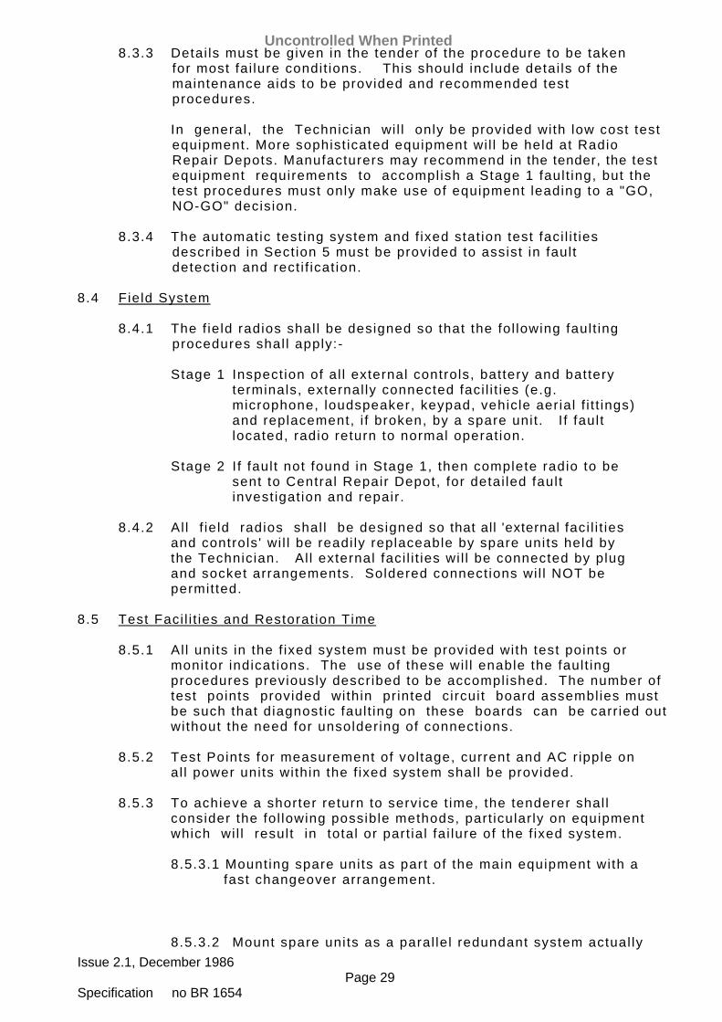
8.3.3 Detai ls must be given in the tender of the procedure to be taken for most fai lure condit ions. This should include detai ls of the maintenance aids to be provided and recommended test procedures.
In general, the Technician wi l l only be provided with low cost test
equipment. More sophist icated equipment wi l l be held at Radio Repair Depots. Manufacturers may recommend in the tender, the test equipment requirements to accomplish a Stage 1 fault ing, but the test procedures must only make use of equipment leading to a "GO, NO-GO" decision.
8.3.4 The automatic test ing system and f ixed stat ion test faci l i t ies
described in Sect ion 5 must be provided to assist in fault detect ion and rect i f icat ion.
8.4 Field System 8.4.1 The f ield radios shal l be designed so that the fol lowing fault ing
procedures shal l apply:- Stage 1 Inspect ion of al l external controls, battery and battery
terminals, external ly connected faci l i t ies (e.g. microphone, loudspeaker, keypad, vehicle aerial f i t t ings) and replacement, i f broken, by a spare unit . I f fault located, radio return to normal operat ion.
Stage 2 I f fault not found in Stage 1, then complete radio to be
sent to Central Repair Depot, for detai led fault invest igat ion and repair.
8.4.2 Al l f ie ld radios shal l be designed so that all 'external faci l i t ies
and controls ' wi l l be readi ly replaceable by spare units held by the Technician. Al l external faci l i t ies wi l l be connected by plug and socket arrangements. Soldered connect ions wi l l NOT be permitted.
8.5 Test Faci l i t ies and Restorat ion Time 8.5.1 Al l units in the f ixed system must be provided with test points or
monitor indicat ions. The use of these wi l l enable the fault ing procedures previously described to be accomplished. The number of test points provided within pr inted circuit board assemblies must be such that diagnost ic fault ing on these boards can be carr ied out without the need for unsoldering of connect ions.
8.5.2 Test Points for measurement of voltage, current and AC r ipple on
al l power units within the f ixed system shal l be provided. 8.5.3 To achieve a shorter return to service t ime, the tenderer shal l
consider the fol lowing possible methods, part icular ly on equipment which wi l l result in total or part ial fai lure of the f ixed system.
8.5.3.1 Mounting spare units as part of the main equipment with a
fast changeover arrangement.
8.5.3.2 Mount spare units as a paral lel redundant system actual ly
Uncontrolled When Printed

Issue 2.1, December 1986 Page 30 Specification no BR 1654
in circuit . 8.5.3.3 Monitor certain test posit ions to provide an "at a glance"
indicat ion. 8.5.3.4 Provide 8.5.3.2 with automatic fault detect ion giving
automatic changeover. Separate quotat ions should be submitted for any of the above
arrangements i f they are not already part of the system being offered.
8.6 Spares Holdings The tenderer shal l provide a separate quotat ion for the fol lowing spare
units and equipments. 8.6.1 At control - any unit or component which wi l l cause a total or
part ial fai lure of the system. The tenderer should state the units which, in his opinion, should be held as spares.
8.6.2 Fixed stat ion and l ine terminat ion. 8.6.3 Microwave l ink terminals ( i f used). 8.7 Routine Maintenance The tender must contain detai ls of al l rout ine maintenance operat ions
which wi l l be necessary, wi th par t icu lar re ference to t ime in terva ls and associated system down t ime.
8.8 Handbooks and Circuit Diagrams 8.8.1 The Contractor shal l prepare al l wir ing diagrams, instal lat ion
programmes and construct ional and layout drawings, and submit two copies to the Bri t ish Rai lways board for approval within a t ime specif ied in the contract. Al l drawings shal l be drawn specif ical ly for this equipment and contain only Engl ish nomenclature. Contractors who are intending to supply drawings not prepared in the UK shal l specif ical ly mention this in their tenders.
8.8.2 The Contractor shal l produce three separate Handbooks. 8.8.2.1 Handbook No. 1 shal l describe the funct ional operat ion and
circuit design of the system in detai l . This handbook is for the use of the Engineers who wi l l provide the 2nd level of maintenance for the f ixed system and wi l l enable these Engineers to modify and extend the system i f
required. 8.8.2.2 Handbook No. 2 shal l be the Telecommunicat ions
Technic ian 's manual to a id 1st leve l maintenance. I t w i l l describe the maintenance and fault f inding procedures to
be adopted on the equipment and shal l also give a simple descr ipt ion of the operat ion and design of the equipment and contain charts detai l ing fault search procedures.
8.8.2.3 Handbook No 3 shal l be a Workshop Manual for use of
Uncontrolled When Printed

Issue 2.1, December 1986 Page 31 Specification no BR 1654
Engineers and Repair Staff at the Centralised Radio Repair Depots. I t wi l l contain a detai led component specif icat ion and al l detai ls necessary to enable the test and repair of equipment to be undertaken.
A fu l l schedu le o f a l l p r in ted c i rcu i t boards and components
thereon, component suppl iers and catalogue numbers of al l components, including plugs, sockets, lamps, lamp holders, keys, etc. shal l be included in this manual.
8.8.3 I t should be noted by the Contractor, that Handbook Nos. 1 and 3
may be deemed as being ident ical, provided that the contents of 8.8.2.1 and 8.8.2.3 are covered by that Handbook.
8.8.4 Two draft copies of each handbook shal l be submitted for approval
and s ix copies per cont ro l area together wi th the f ina l drawings shal l be provided after these have been approved. Negatives or microf i lm of the f inal drawings shal l also be provided.
8.8.5 I t should be noted by the Contractor that the system is not deemed
maintainable by BR or by Contract unt i l up to date, correct, documentat ion as specif ied above has been del ivered. The Warranty period shal l only commence on receipt of this documentat ion.
8.9 Label l ing The Contractor shal l ensure that al l equipment is clearly label led for
ease of ident i f icat ion of uni ts and terminat ions. Part icular at tent ion must be paid to the fol lowing:-
8.9.1 Al l cubicles, board and unit posit ions shal l be numbered front and
rear. 8.9.2 The funct ion of each unit , and of groups of pr inted circuit boards
shal l be clearly label led. 8.9.3 Al l tag blocks and terminal numbering must be clearly label led. 8.9.4 In general, i t must be easy to ident i fy individual units,
components or terminals by referr ing to the drawings and to an appropriate equipment label.
8.9.5 Each individual unit must carry a unique serial number, which wi l l
incorporate any code numbers of modif icat ion state.
Uncontrolled When Printed
Issue 2.1, December 1986 Page 32 Specification no BR 1654
PART 9 SUPPLY AND INSTALLATION TESTING COMMISSIONING WARRANTY PERIOD 9.1 Supply and Instal lat ion 9.1.1 The Contractor wi l l nominate a Project Engineer who shal l be
responsible for the co-ordinat ion of al l the Contractor 's act iv i t ies in respect of the contract during the engineering and commissioning stages and in the one year Warranty period.
9.1.2 The Contractor wi l l also nominate a si te supervisor who, in
addit ion to taking other dut ies, wi l l be responsible for maintaining the si tes of work in a clean and t idy condit ion unt i l such t ime that the equipment is taken over.
9.1.3 The Cont rac to r w i l l p rov ide fac i l i t i es dur ing the con t rac t per iod
for the inspect ion of works and drawings in order that an assessment of the progress of the contract may be made.
9.1.4 The Contractor shal l be responsible for the supply of al l equipment
necessary to complete the instal lat ion work other than as excluded by the schedule.
9.1.5 The fol lowing wi l l be provided to the Contractor by BR:- (1) Mains Power Supply Points (240 or 110V ac) terminated at
ei ther a fused spur or socket out lets. (2) PTO or BR Remote Control Lines terminated on an approved block
terminal. (3) Aerials, Feeders and Masts. 9.1.6 During the period of the Contractor 's manufacture of the equipment
the Contractor shal l provide short instruct ional courses at his works for members of BR Maintenance Staff , i f required.
9.2 Testing 9.2.1 BR wi l l require a complete system test to be carr ied out at the
contractor 's premises pr ior to the release of equipment to si te for instal lat ion, where al l specif ied t imings, levels and abi l i ty to carry data telegrams successful ly etc., wi l l be checked. Records for the same shal l be produced.
9.2.2 I t shal l be the responsibi l i ty of the Contractor to ensure that
the equipment is in a ful ly operat ional state both for factory test ing and si te test ing by BR.
Uncontrolled When Printed
Issue 2.1, December 1986 Page 33 Specification no BR 1654
9.2.3 The contractor shal l provide wri t ten proof in the form of a test cert i f icate that al l tests cal led for in the specif icat ion have been carr ied out.
9.2.4 The Contractor shal l give every faci l i ty and assistance to the
Director of S & T Engineering and his representat ives in test ing, programming and checking the working and method of instal lat ion of the radio system equipment both at the Contractor 's works and on si te.
9.2.5 The Contractor shal l give the Director of S & T Engineering
7 days not ice when the equipment is ready for test. 9.3 Commissions 9.3.1 The proposed dates for the introduct ion of the scheme are shown
in the schedule attached to this specif icat ion. 9.3.2 The Contractor shal l give detai ls of the ant ic ipated
commissioning schedule assuming that BR has provided al l the necessary faci l i t ies.
9.3.3 Ful l commissioning records giving detai ls of equipment serial
numbers, levels, faults and rect i f icat ion, etc., shal l be kept and handed to the Engineer before the Acceptance document is presented for signature.
9.3.4 Dur ing the t ime the tes t ing , ins ta l la t ion and commiss ion ing i s in
progress, the Director of S & T Engineering shal l be at l iberty to place suitable men with the Contractor for the purpose of acquir ing the requisi te knowledge in order to maintain the equipment after being brought into use. The Contractor shal l be able to ut i l ise the services of these men, always keeping in mind the purpose for which they were placed with him. During the t ime these men are under the supervision of the Contractor their wages shal l be paid by BR but the Contractor shal l reimburse BR for wages paid in respect of overt ime or Sunday duty.
9.4 Warranty Period The Contractor shal l be responsible for the system suppl ied during the
one year Warranty period as fol lows:- 9.4.1 Fixed System Including al l Battery Chargers Al l faults to be cleared within 24 hours of not i f icat ion to the
suppl iers nominated repair depot. I t is ant ic ipated that BR staff wi l l have ident i f ied the nature
of the fault and i f possible replaced the fai led unit with a spare before cal l ing the nominated depot. I f spares are not avai lable or the fault cannot be located to one part icular piece of equipment the Contractor wi l be expected to attend si te within 12 hours to meet his warranty l iabi l i t ies.
9.4.2 Mobi le and Portable Radios (I f cal led for in the Schedule)
Uncontrolled When Printed

Issue 2.1, December 1986 Page 34 Specification no BR 1654
Mobi le and Portable Radio faults must be cleared and the unit
returned to the user locat ion within 5 working days from receipt of the faulty unit by the Contractor, at his premises.
Al ternat ively, replacement radios must be provided within the
above t ime l imit , as part of the Warranty. 9.4.3 The Warranty period shal l commence when the Board's Engineer
signs the cert i f icate of acceptance for the scheme. 9.4.4 The Warranty shal l cover parts and labour.
Uncontrolled When Printed

Issue 2.1, December 1986 Page 35 Specification no BR 1654
PART 10 SAFETY REQUIREMENTS 10.1 The equipment shal l conform to BS 6301. The equipment shal l not
extend excessive voltages, as def ined in the Bri t ish Standard, to any of i ts outputs when working, when faulty or when being worked on.
10.2 Al l equipment shal l conform to the appropriate Regulat ions and
Statutory requirements of the Health and Safety at Work Act 1974. PART 11 OVERVOLTAGE LINE PROTECTION Overvoltage l ine protect ion shal l be provided within the equipment. The
protect ion shal l include precautions against the effects of l ightning s t r i kes and the e f fec ts o f e lec t r i f i ed t rac t ion as de ta i led in C lause 13 .
PART 12 ANTI-STATIC PRECAUTIONS 12.1 Al l apparatus shal l be protected from the effects of stat ic
electr ic i ty during manufacture, instal lat ion, and subsequent maintenance.
12.2 Where the apparatus requires ant i-stat ic precautions to be
appl ied during maintenance work, earthed male 10 mm studs shal l be provided on each working face of the apparatus for the connect ion of wrist straps.
Uncontrolled When Printed

Issue 2.1, December 1986 Page 36 Specification no BR 1654
PART 13 AC AND DC ELECTRIFIED AREAS The cable to which the equipment is to be connected may be laid
alongside a rai lway l ine electr i f ied on the 25 kV, 50 Hz, overhead or the 750 V DC third rai l system.
Electromagnetical ly induced longitudinal voltages wi l l be produced
on the cable pairs by both types of tract ion system. 13.1 No degradation of service ei ther switching or transmission
shal l occur under the fol lowing normal operat ing condit ions. 13.1.1 On 25kV Systems Induct ion at the fundamental f requency (50 Hz) wi l l
produce voltages up to 60 V rms. The induced voltage wi l l include harmonics and in the audio frequency band al l odd harmonics of 50 Hz wi l l be present,
the i r ampl i tude genera l l y reduc ing w i th inc rease o f frequency. I t can be assumed that the harmonic components of induct ion wi l l result in a
longitudinal "weighted" voltage up to an equivalent of 5 V rms (CCITT psophometr ic weight ing).
13.1.2 On 750 V DC Systems The induced voltage is a by-product of the tract ion
supply rect i f icat ion system and wi l l consist of components at 300, 600, 900, 1200, (and 1500) Hz, the dominant frequency normally being 600 Hz. Induct ion containing these frequencies may exist at voltages up to 10 V rms. Due to the way in which these a.c. components are produced and distr ibuted the resultant (net) induced voltage waveform wil l not be sinusoidal and as a result peak-to-peak voltages wi l l general ly not exceed 40 Volts.
13.2 25 kV Systems No damage shal l be caused to the equipment under the
fol lowing tract ion fault condit ions on 25 kV systems. The maximum induced voltage occurr ing on l ineside cable
conductors wi l l be 430 V rms. The fault condit ion durat ion wi l l not exceed 200 mi l l iseconds. The in i t ia l surge vo l tage, produced as the faul t occurs, wi l l contain a t ransient which can cause the peak voltage within 5 mil l iseconds of the incident of such a fault to approach 1000 V.
13.3 750 V d.c. Systems The cable sheath wi l l general ly be isolated from earth to
prevent tract ion return currents f lowing in the cable sheath under tract ion fault condit ions.
Uncontrolled When Printed

Issue 2.1, December 1986 Page 37 Specification no BR 1654
13.4 Power Line Paral lel isms Where the rai lway cable route runs paral lel to an adjacent
electr ic i ty overhead HV distr ibut ion system, induct ion of 50 Hz can reach 60 V rms under normal HV l ine operat ing condit ions and 430/ 650 V (200 mil l iseconds durat ion) under HV l ine fault condit ions, the maximum voltage l imit depending on the class of HV l ine involved.
No degradation of the service, shal l occur under normal HV
operat ing condit ions and the equipment shal l suffer no damage as a result of the HV fault .
13.5 Balance to Earth The balance to earth presented by the equipment shal l
preferably be better than 66 dB but in any case shal l not be worse than 60 db, over the frequency range 50 - 3400 Hz. This balance to earth shal l be maintained when the equipment is subject to any combinat ion of voltages on the connected cable pair as detai led in Clause 13.1 above.
Uncontrolled When Printed

38
Uncontrolled When Printed

39
Uncontrolled When Printed

Appendix C. Band III Channel Plan HEX IDENTITY DTI CHANNEL No. BASE TX BASE RX 0 0
213 203.1500 195.1500
0 1
214 203.1625 195.1625
0 2
215 203.1750 195.1750
0 3
216 203.1875 195.1875
0 4
217 203.2000 195.2000
0 5
218 203.2125 195.2125
0 6
219 203.2250 195.2250
0 7
220 203.2375 195.2375
0 8
221 203.2500 195.2500
0 9
222 203.2625 195.2625
0 A
223 203.2750 195.2750
0 B
224 203.2875 195.2875
0 C
225 203.3000 195.3000
226 203.3125 195.3125
Uncontrolled When Printed

0 D 0 E
227 203.3250 195.3250
0 F
228 203.3375 195.3375
1 0
229 203.3500 195.3500
1 1
230 203.3625 195.3625
1 2
231 203.3750 195.3750
1 3
232 203.3875 195.3875
1 4
233 203.4000 195.4000
1 5
234 203.4125 195.4125
1 6
235 203.4250 195.4250
1 7
236 203.4375 195.4375
1 8
237 203.4500 195.4500
1 9
238 203.4625 195.4625
1 A
239 203.4750 195.4750
1 B
240 203.4875 195.4875
Uncontrolled When Printed

1 C
241 203.5000 195.5000
1 D
242 203.5125 195.5125
1 E
243 203.5250 195.5250
1 F
244 203.5375 195.5375
2 0
245 203.5500 195.5500
2 1
246 203.5625 195.5625
2 2
247 203.5750 195.5750
2 3
248 203.5875 195.5875
2 4
249 203.6000 195.6000
2 5
250 203.6125 195.6125
2 6
251 203.6250 195.6250
2 7
252 203.6375 195.6375
2 8
253 203.6500 195.6500
2 9
254 203.6625 195.6625
2
255 203.6750 195.6750
Uncontrolled When Printed

A 2 B
256 203.6875 195.6875
2 C
257 203.7000 195.7000
2 D
258 203.7125 195.7125
2 E
259 203.7250 195.7250
2 F
260 203.7375 195.7375
3 0
261 203.7500 195.7500
3 1
262 203.7625 195.7625
3 2
263 203.7750 195.7750
Appendix C Page 1
Uncontrolled When Printed
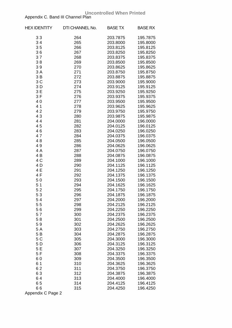
Appendix C. Band III Channel Plan HEX IDENTITY DTI CHANNEL No. BASE TX BASE RX 3 3 264 203.7875 195.7875 3 4 265 203.8000 195.8000 3 5 266 203.8125 195.8125 3 6 267 203.8250 195.8250 3 7 268 203.8375 195.8375 3 8 269 203.8500 195.8500 3 9 270 203.8625 195.8625 3 A 271 203.8750 195.8750 3 B 272 203.8875 195.8875 3 C 273 203.9000 195.9000 3 D 274 203.9125 195.9125 3 E 275 203.9250 195.9250 3 F 276 203.9375 195.9375 4 0 277 203.9500 195.9500 4 1 278 203.9625 195.9625 4 2 279 203.9750 195.9750 4 3 280 203.9875 195.9875 4 4 281 204.0000 196.0000 4 5 282 204.0125 196.0125 4 6 283 204.0250 196.0250 4 7 284 204.0375 196.0375 4 8 285 204.0500 196.0500 4 9 286 204.0625 196.0625 4 A 287 204.0750 196.0750 4 B 288 204.0875 196.0875 4 C 289 204.1000 196.1000 4 D 290 204.1125 196.1125 4 E 291 204.1250 196.1250 4 F 292 204.1375 196.1375 5 0 293 204.1500 196.1500 5 1 294 204.1625 196.1625 5 2 295 204.1750 196.1750 5 3 296 204.1875 196.1875 5 4 297 204.2000 196.2000 5 5 298 204.2125 196.2125 5 6 299 204.2250 196.2250 5 7 300 204.2375 196.2375 5 8 301 204.2500 196.2500 5 9 302 204.2625 196.2625 5 A 303 204.2750 196.2750 5 B 304 204.2875 196.2875 5 C 305 204.3000 196.3000 5 D 306 204.3125 196.3125 5 E 307 204.3250 196.3250 5 F 308 204.3375 196.3375 6 0 309 204.3500 196.3500 6 1 310 204.3625 196.3625 6 2 311 204.3750 196.3750 6 3 312 204.3875 196.3875 6 4 313 204.4000 196.4000 6 5 314 204.4125 196.4125 6 6 315 204.4250 196.4250 Appendix C Page 2
Uncontrolled When Printed
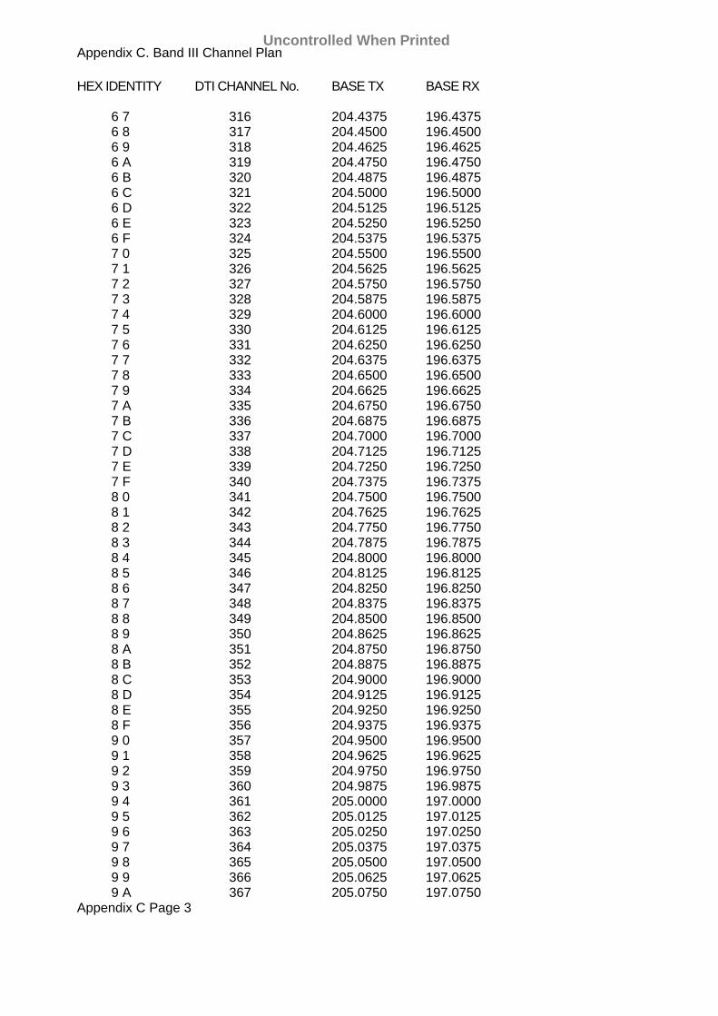
Appendix C. Band III Channel Plan HEX IDENTITY DTI CHANNEL No. BASE TX BASE RX 6 7 316 204.4375 196.4375 6 8 317 204.4500 196.4500 6 9 318 204.4625 196.4625 6 A 319 204.4750 196.4750 6 B 320 204.4875 196.4875 6 C 321 204.5000 196.5000 6 D 322 204.5125 196.5125 6 E 323 204.5250 196.5250 6 F 324 204.5375 196.5375 7 0 325 204.5500 196.5500 7 1 326 204.5625 196.5625 7 2 327 204.5750 196.5750 7 3 328 204.5875 196.5875 7 4 329 204.6000 196.6000 7 5 330 204.6125 196.6125 7 6 331 204.6250 196.6250 7 7 332 204.6375 196.6375 7 8 333 204.6500 196.6500 7 9 334 204.6625 196.6625 7 A 335 204.6750 196.6750 7 B 336 204.6875 196.6875 7 C 337 204.7000 196.7000 7 D 338 204.7125 196.7125 7 E 339 204.7250 196.7250 7 F 340 204.7375 196.7375 8 0 341 204.7500 196.7500 8 1 342 204.7625 196.7625 8 2 343 204.7750 196.7750 8 3 344 204.7875 196.7875 8 4 345 204.8000 196.8000 8 5 346 204.8125 196.8125 8 6 347 204.8250 196.8250 8 7 348 204.8375 196.8375 8 8 349 204.8500 196.8500 8 9 350 204.8625 196.8625 8 A 351 204.8750 196.8750 8 B 352 204.8875 196.8875 8 C 353 204.9000 196.9000 8 D 354 204.9125 196.9125 8 E 355 204.9250 196.9250 8 F 356 204.9375 196.9375 9 0 357 204.9500 196.9500 9 1 358 204.9625 196.9625 9 2 359 204.9750 196.9750 9 3 360 204.9875 196.9875 9 4 361 205.0000 197.0000 9 5 362 205.0125 197.0125 9 6 363 205.0250 197.0250 9 7 364 205.0375 197.0375 9 8 365 205.0500 197.0500 9 9 366 205.0625 197.0625 9 A 367 205.0750 197.0750 Appendix C Page 3
Uncontrolled When Printed

Appendix C. Band III Channel Plan HEX IDENTITY DTI CHANNEL No. BASE TX BASE RX 9 B 368 205.0875 197.0875 9 C 369 205.1000 197.1000 9 D 370 205.1125 197.1125 9 E 371 205.1250 197.1250 9 F 372 205.1375 197.1375 A 0 373 205.1500 197.1500 A 1 374 205.1625 197.1625 A 2 375 205.1750 197.1750 A 3 376 205.1875 197.1875 A 4 377 205.2000 197.2000 A 5 378 205.2125 197.2125 A 6 379 205.2250 197.2250 A 7 380 205.2375 197.2375 A 8 381 205.2500 197.2500 A 9 382 205.2625 197.2625 A A 383 205.2750 197.2750 A B 384 205.2875 197.2875 A C 385 205.3000 197.3000 A D 386 205.3125 197.3125 A E 387 205.3250 197.3250 A F 388 205.3375 197.3375 B 0 389 205.3500 197.3500 B 1 390 205.3625 197.3625 B 2 391 205.3750 197.3750 B 3 392 205.3875 197.3875 B 4 393 205.4000 197.4000 B 5 394 205.4125 197.4125 B 6 395 205.4250 197.4250 B 7 396 205.4375 197.4375 B 8 397 205.4500 197.4500 B 9 398 205.4625 197.4625 B A 399 205.4750 197.4750 B B 400 205.4875 197.4875 B C 401 205.5000 197.5000 B D 402 205.5125 197.5125 B E 403 205.5250 197.5250 B F 404 205.5375 197.5375 C 0 405 205.5500 197.5500 C 1 406 205.5625 197.5625 C 2 407 205.5750 197.5750 C 3 408 205.5875 197.5875 C 4 409 205.6000 197.6000 C 5 410 205.6125 197.6125 C 6 411 205.6250 197.6250 C 7 412 205.6375 197.6375 C 8 413 205.6500 197.6500 C 9 414 205.6625 197.6625 C A 415 205.6750 197.6750 C B 416 205.6875 197.6875 C C 417 205.7000 197.7000 C D 418 205.7125 197.7125 C E 419 205.7250 197.7250 Appendix C Page 4
Uncontrolled When Printed
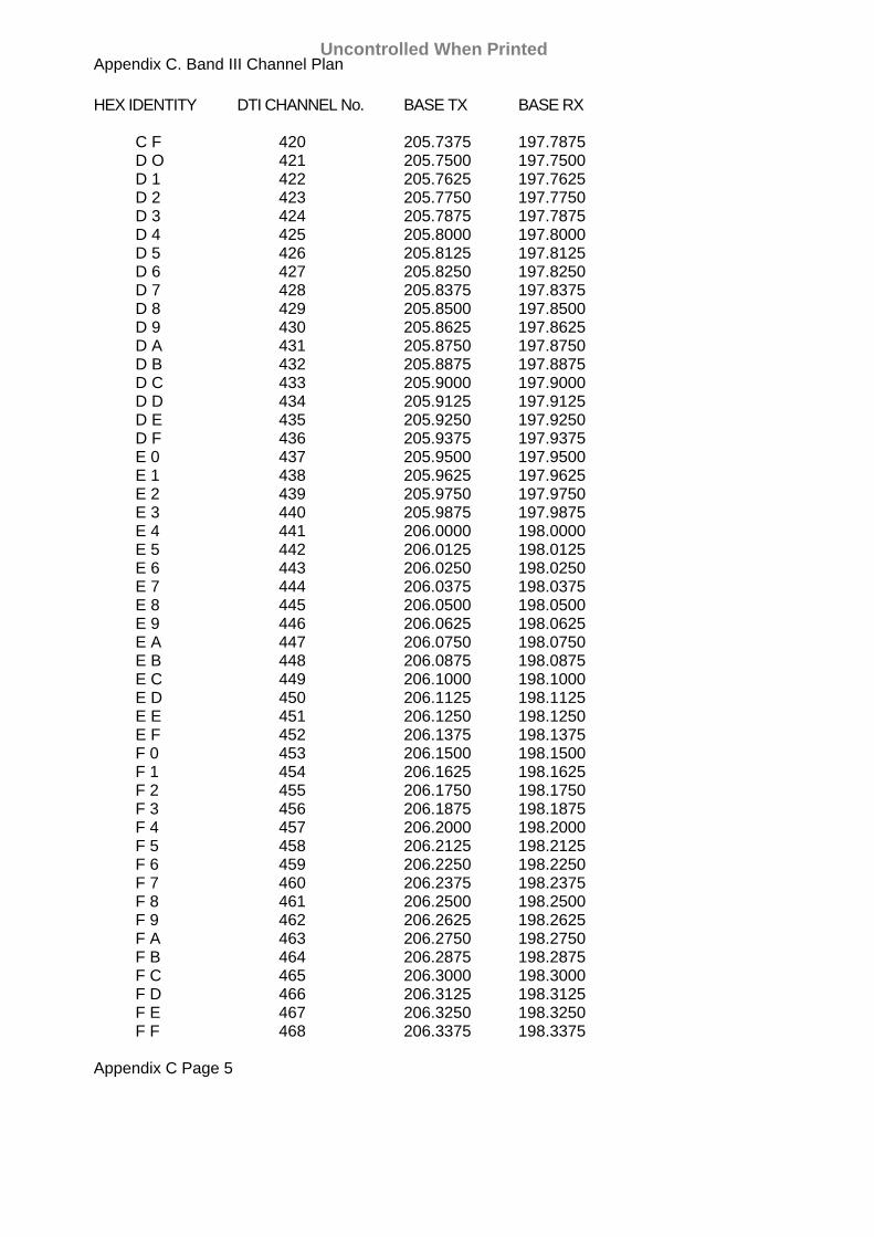
Appendix C. Band III Channel Plan HEX IDENTITY DTI CHANNEL No. BASE TX BASE RX C F 420 205.7375 197.7875 D O 421 205.7500 197.7500 D 1 422 205.7625 197.7625 D 2 423 205.7750 197.7750 D 3 424 205.7875 197.7875 D 4 425 205.8000 197.8000 D 5 426 205.8125 197.8125 D 6 427 205.8250 197.8250 D 7 428 205.8375 197.8375 D 8 429 205.8500 197.8500 D 9 430 205.8625 197.8625 D A 431 205.8750 197.8750 D B 432 205.8875 197.8875 D C 433 205.9000 197.9000 D D 434 205.9125 197.9125 D E 435 205.9250 197.9250 D F 436 205.9375 197.9375 E 0 437 205.9500 197.9500 E 1 438 205.9625 197.9625 E 2 439 205.9750 197.9750 E 3 440 205.9875 197.9875 E 4 441 206.0000 198.0000 E 5 442 206.0125 198.0125 E 6 443 206.0250 198.0250 E 7 444 206.0375 198.0375 E 8 445 206.0500 198.0500 E 9 446 206.0625 198.0625 E A 447 206.0750 198.0750 E B 448 206.0875 198.0875 E C 449 206.1000 198.1000 E D 450 206.1125 198.1125 E E 451 206.1250 198.1250 E F 452 206.1375 198.1375 F 0 453 206.1500 198.1500 F 1 454 206.1625 198.1625 F 2 455 206.1750 198.1750 F 3 456 206.1875 198.1875 F 4 457 206.2000 198.2000 F 5 458 206.2125 198.2125 F 6 459 206.2250 198.2250 F 7 460 206.2375 198.2375 F 8 461 206.2500 198.2500 F 9 462 206.2625 198.2625 F A 463 206.2750 198.2750 F B 464 206.2875 198.2875 F C 465 206.3000 198.3000 F D 466 206.3125 198.3125 F E 467 206.3250 198.3250 F F 468 206.3375 198.3375 Appendix C Page 5
Uncontrolled When Printed

Appendix E Signalling Section Research & Development Division Ref: 206-10-32/MJF RB 3 Date: 6 March 79 Amended 2 July 79
Item 2 Sept 1986 Specification BR 1654
RADIO OPERATION OF BLOCK SIGNALLING INSTRUMENTS. Electrical Specification of Connections Between Control Unit and Radio. 1. GENERAL. Connection to the radio is made from the Control Unit on the fourteen
way connector (A) the connector terminates three cables: (a) TX Audio - screened (b) RX Audio - screened (c) T/R Control and Audio Disable - unscreened The screens of (a) and (b) above are terminated within the Control Unit
and must not be connected at the radio end. 2. ELECTRICAL SPECIFICATION. 2.1 TX Audio output from the Control Unit. Source type: Transformer, balanced winding. Source current: 1.25 mA RMS + 10% into 600 ohms, constant current. Load Type: Transformer, balanced winding. Load Connection Point: Before low pass filter and modulator. 2.2 RX Audio input to Control Unit. Source Connection Point: Before de-emphasis, not band width limited. Source Type: Transformer, balance winding. Source Impedance: ≤ 600 ohms. Source EMF: 250 mV + 20% Load: 5 K ohms per Control Unit (max 4). Load Type: Transformer, balanced winding. 2.3 T/R Control. Return: via Radio Ground. Mode (a) Local transmitter available, input. Load Current: 1 mA per Control Unit (max 4). Load Current Polarity: Negative with respect to
Radio Ground.
Uncontrolled When Printed
Appendix E
Item 2 Sept 1986 Specification BR 1654
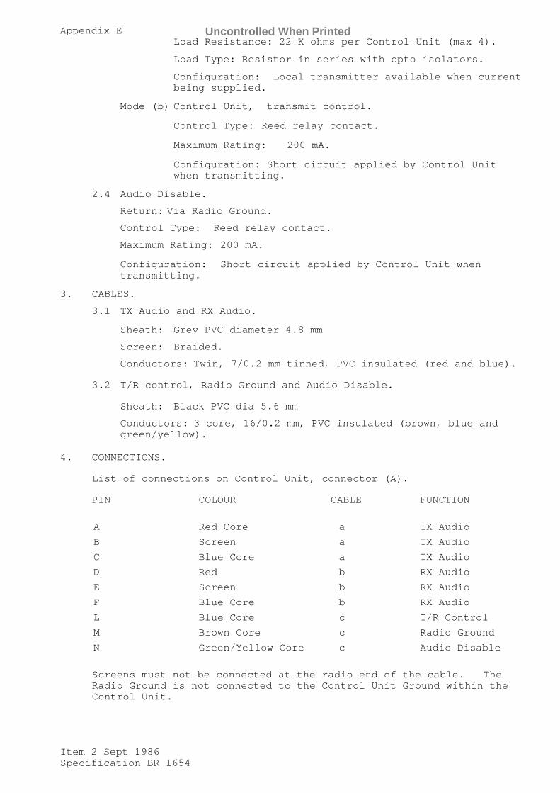
Load Resistance: 22 K ohms per Control Unit (max 4).
Load Type: Resistor in series with opto isolators.
Configuration: Local transmitter available when current being supplied.
Mode (b) Control Unit, transmit control.
Control Type: Reed relay contact.
Maximum Rating: 200 mA.
Configuration: Short circuit applied by Control Unit when transmitting.
2.4 Audio Disable.
Return: Via Radio Ground.
Control Type: Reed relay contact.
Maximum Rating: 200 mA.
Configuration: Short circuit applied by Control Unit when transmitting.
3. CABLES.
3.1 TX Audio and RX Audio. Sheath: Grey PVC diameter 4.8 mm
Screen: Braided.
Conductors: Twin, 7/0.2 mm tinned, PVC insulated (red and blue).
3.2 T/R control, Radio Ground and Audio Disable.
Sheath: Black PVC dia 5.6 mm
Conductors: 3 core, 16/0.2 mm, PVC insulated (brown, blue and green/yellow).
4. CONNECTIONS.
List of connections on Control Unit, connector (A). PIN COLOUR CABLE FUNCTION
A Red Core a TX Audio
B Screen a TX Audio
C Blue Core a TX Audio
D Red b RX Audio
E Screen b RX Audio
F Blue Core b RX Audio
L Blue Core c T/R Control
M Brown Core c Radio Ground
N Green/Yellow Core c Audio Disable
Screens must not be connected at the radio end of the cable. The
Radio Ground is not connected to the Control Unit Ground within the Control Unit.
Uncontrolled When Printed

Uncontrolled When Printed

BRITISH RAILWAYS BOARD, RESEARCH & DEVELOPMENT ELS/A4/3310 ISSUE A DIVISION, DERBY DRG.DATE ISSUE DATE 23/2/84
ELS/A4/3310 sheet 1 of 3 sheets
MRAC INTERFACE MODULE - INTERNAL CONNECTIONS 75P PIN NO. FUNCTION CONNECTED TO:- PIN
NO.
5v FROM PSU CON 1 1
OV FROM PSU CON 1 2
1 TX DATA FROM MPM'S CON 1 3
2 " " " " " " 4
3 " " " " " " 5
4 TX DATA - OV " " 35
5 " " " " " 36
7 " " " " " 37
8 TX/RX CONTROL FROM MPMS " " 6
10 " " " " " " 7
11 " " " " " " 8
12 TX/RX CONTROL - OV " " 44
13 " " " " " 45
14 " " " " " 46
15 TX/RX CLK FROM MPMS " " 9
16 " " " " " " 10
17 " " " " " " 11
18 TX/RX CLK - OV " " 38
20 " " " " " 39
21 " " " " " 40
22 RX DATA FROM MPMS " " 12
23 " " " " " " 13
24 " " " " " " 14
25 RX DATA - OV " " 41
26 " " " " " 42
Uncontrolled When Printed

BRITISH RAILWAYS BOARD, RESEARCH & DEVELOPMENT ELS/A4/3310 ISSUE A DIVISION, DERBY DRG.DATE ISSUE DATE 23/2/84
ELS/A4/3310 sheet 2 of 3 sheets
MRAC INTERFACE MODULE - INTERNAL CONNECTIONS 75P PIN NO. FUNCTION CONNECTED TO:- PIN
NO.
27 RX DATA - OV CON 1 43
28 TX KEY O/P CON 1 23
29 TX DATA O/P CON 1 15
30 TX CLK I/P " " 17
31 RX DATA I/P " " 19
32 RX CLK I/P " " 21
" "
40 110V AC SUPPLY PSU
41 110 V AC NEUTRAL PSU
42 EARTH (FROM EARTH BUS0 PSU
49 SQUELCH I/P CON 2 1
50 PTT I/P " " 2
51 7X INHIBIT O/P " " 20
52 CTS O/P TO MPMS " " 3
53 " " " " " " 4
54 " " " " " " 5
55 CTS - OV " " 7
56 " " " " 9
57 " " " " 11
58 TX DATA O/P - OV " " 12
59 TX KEY O/P - OV " " 13
60 TX INHIBIT O/P - OV " " 14
62 TX CLK I/P - OV " " 15
63 RX DATA 1/9 - OV " " 16
Uncontrolled When Printed
BRITISH RAILWAYS BOARD, RESEARCH & DEVELOPMENT ELS/A4/3310 ISSUE A DIVISION, DERBY DRG.DATE ISSUE DATE 23/2/84
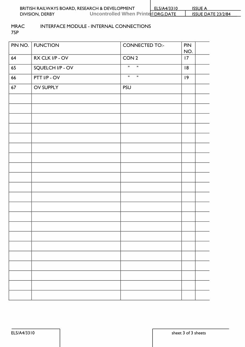
ELS/A4/3310 sheet 3 of 3 sheets
MRAC INTERFACE MODULE - INTERNAL CONNECTIONS 75P PIN NO. FUNCTION CONNECTED TO:- PIN
NO.
64 RX CLK I/P - OV CON 2 17
65 SQUELCH I/P - OV " " 18
66 PTT I/P - OV " " 19
67 OV SUPPLY PSU
Uncontrolled When Printed

BR 1654
Uncontrolled When Printed