unclassified 401 068 - defense technical …dtic.mil/dtic/tr/fulltext/u2/407068.pdfunclassified 401...
TRANSCRIPT
UNCLASSIFIED
401 068
DEFENSE DOCUMENTATION CENTER":OR
SCIENTIFIC AND TECHNICAL INFORMATION
CAMERON STATION. AlEXANDRIA. VIRGINIA
UNCLASS1tIFIED

NOTICE: When government or other drawings, speci-fications or other data are used for any purposeother than in connection with a definitely relatedgovernment procurement operation, the U. S.Government thereby incurs no responsibility, nor anyobligation whatsoever; and the fact that the Govern-ment may have formulated, furnished, or in any waysupplied the said drawings, specifications, or otherdata is not to be regarded by implication or other-wise as in any manner licensing the holder or anyother person or corporation, or conveying any rightsor permission to manufacture, use or sell anypatented invention that may in any way be relatedthereto.
FTC-TIH-63-2001 407 068 63
JOINTPARACHUTE
C.. K~ r 4 \>N>"~\ TESTcz~ ~A~ % FACILITY
j7/USAF651h¼l TEST GROUP
Lii3cm (PARACHUTE)
SC/)
and
US NAVAL
PARACHUTE
FACILITY
REVISED-MAY 1963 0
TISIA D

H ~ 7a S

/V
The purpose of \this publicati.ntst deýrL t ion Ifarachute Test Facilityoperated by the'Unitied Sto~e HNavy and th e' Unied1Stotes Air Force. The NavalParaht Filtyadhe6'511,th Par Iclute1 6't ro nakb e joned together inthe operation and ujtili.zat'ion 6f one iesoi~ng cm'ple to, achieve each service'sspecific objectivesrel'a~ii~e~to the testip~g 'of'r arIat 'sy ý stems. The equipment
and specialized exp`6rin~ce o'aillabl' a tI o~rgahza'tio'n, have been utilized inthe solution of particu oar' pro'en~s o.r aJll miliýtary servl~cs and also for manyindustrial organ izati ois'. \ticýi mnp ro~ermenI'is ore/co4 stoa'tly being accomplished,
man ofth laes and en 'n~ot be reflected in thisdocument. If additional ji~b 'a'tio 1W e~,/l Fi A 'be obtained from theCommander of either the Iid Fach, 01iflt Wr the 6511th Test Group(Parachute). \
......... --------
12
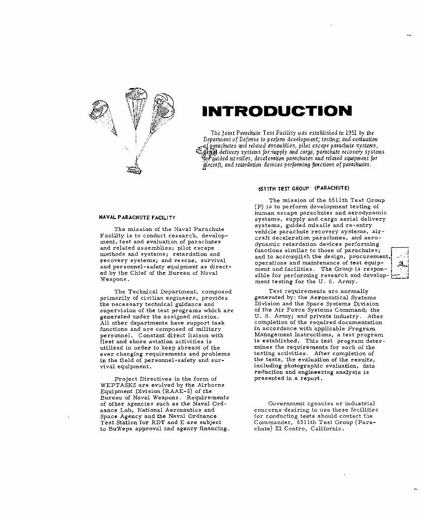
INTRODUCTIONThe joint Parachute Test Facility was establi-shed in 1951 by the
Department of Defense to perform development; testing; and evaluation• _o,'f parachutes and related assemblies, pilot escape parachute ,systemns,
a, ie delivery systems for supply and cargo, parachute recovery systems// 'for ided mi'ssiles, deceleration parachutes and related equipment for
k ircraft, and retardation devices perfonning functions of parachutes.
6511TH TEST GROUP (PARACHUTE)
The mission of the 6511th Test Group(P) is to perform development testing ofhuman escape parachutes and aerodynamic
NAVAL PARACHUTE FACILITY systems, supply and cargo aerial deliverysystems, guided missile and re-entry
The mission of the Naval Parachute vehicle parachute recovery systems, air-Facility is to conduct research, develop- craft deceleration parachutes, and aero-ment, test and evaluation of parachutes dynamic retardation devices performingand related assemblies; pilot escape functions similar to those of parachutes;methods and systems; retardation and and to accomplish the design, procurement,recovery systems; and rescue, survival operations and maintenance of test equip-and personnel-safety equipment as direct- oprtnsadmieaceftstqu- 3
ed b th Chef o th Bueau f Nvalment and facilities. The Group is respon-ed by the Chief of the Bureau of Naval sible for performing research and develop-Weapons. ment testing for the U. S. Army.
The Technical Department, composed Test requirements are normallyprimarily of civilian engineers, provides generated by: the Aeronautical Systemsthe necessary technical guidance and Division and the Space Systems Divisionsupervision of the test programs which are of the Air Force Systems Command; thegenerated under the assigned mission. U. S. Army; and private industry. AfterAll other departments have support task completion of the required documentationfunctions and are composed of military in accordance with applicable Programpersonnel. Constant direct liaison with Management Instructions, a test programfleet and shore aviation activities is is established. This test program deter-utilized in order to keep abreast of the mines the requirements for each of theever changing requirements and problems testing activities. After completion ofin the field of personnel-safety and sur- the tests, the evaluation of the results,vival equipment. including photographic evaluation, data
reduction and engineering analysis is
Project Directives in the form of presented in a report.WEPTASKS are evolved by the AirborneEquipment Division (RAAE-2) of theBureau of Naval Weapons. Requirementsof other agencies such as the Naval Ord- Government agencies or industrialnance Lab, National Aeronautics and concerns desiring to use these facilitiesSpace Agency and the Naval Ordnance for conducting tests should contact theTest Station for RDT and E are subject Commander, 6511th Test Group (Para-to BuWeps approval and agency financing, chute) El Centro, California.

JOINTSUPPORTING
FACILITIES
MATERIALS LABORATORY
The Materials Laboratory is eqippedwith a full line of textile machines andequipment. Prominent among these arethree tensile testing machines with capac-ities of 5,000, 20,000 and 125,000 pounds.The latter machine is designed especiallyfor textile webbing in that it has the travelrequired for testing high elongation materi-als. Other equipment includes a Tinius-Olsen Tensile Tester, Elmendorf TearTester, Sheafer Abrasion Machine, AirPermeability Machine, Weather-Ometerand an Altitude Temperature-HumidityChamber.
WEATHER CHAMBER AND SALT SPRAY
INSTRO TENSILE TESTER
CHECKING POROSITY
TESTING ABRASION QUALITIES OF WEBBING
e/
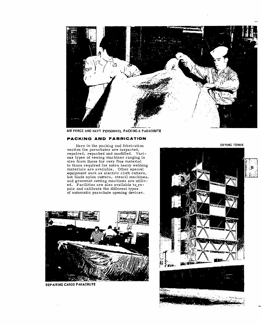
AIR FORCE AND NAVY PERSONNEL PACKING A PARACHUTE
PACKING AND FABRICATION
Here in the packing and fabrication DRYING TOWER
section the parachutes are inspected,repaired, repacked and modified. Vari-ous types of sewing machines ranging insize from those for very fine materialto those required for extra heavy webbingmaterials are available. Other special P IEZIequipment such as electric cloth cutters,hot blade nylon cutters, stencil machines,and grommet setting machines are utiliz-ed. Facilities are also available to re-pair and calibrate the different typesof automatic parachute opening devices.
REPAIRING CARGO PARACHUTE-••. , ... . , . .....

CHECKING THE TELEMETER PACKAGE INSTRUMENTATION
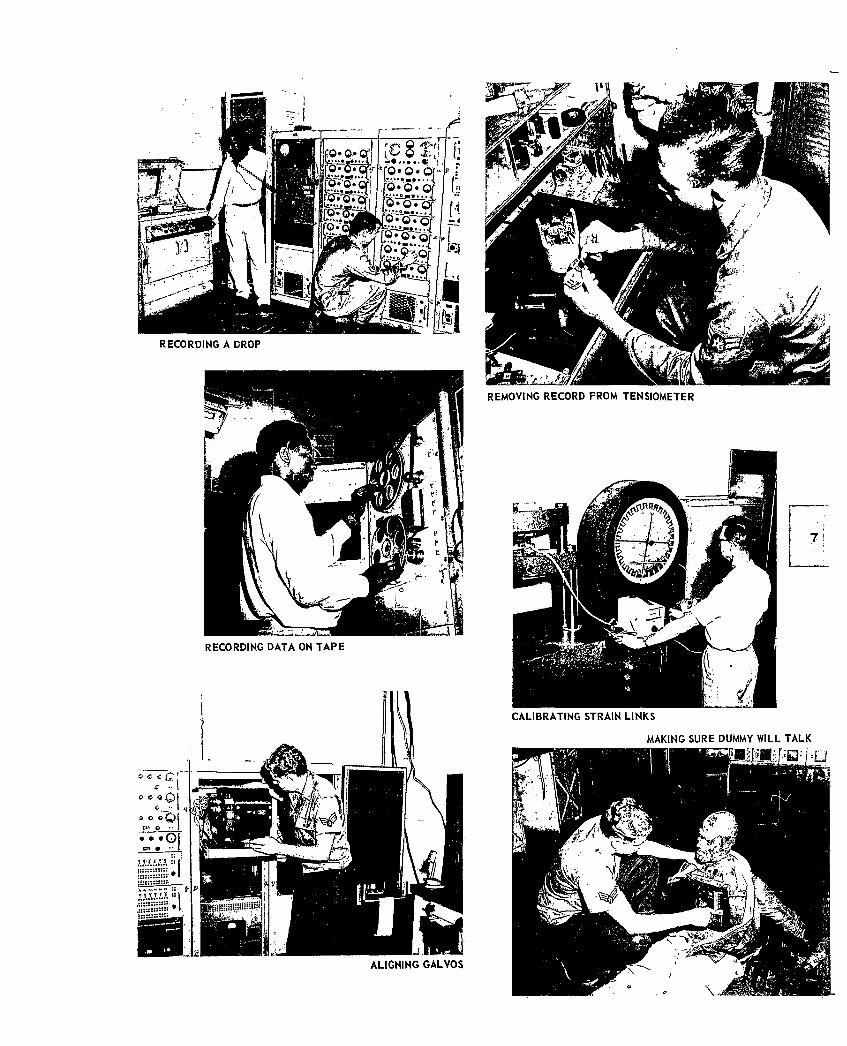
SInstrum entation personnel translatethe project engineers' requirements intothe equipment necessary to measure and"record the multitude of test parameters.
d al Since each project presents peculiarS~problems, the experience and ingenuity
of the instrumentation engineers andtechnicians play an important part in theacquisition of reliable data. Any specialitems required, but not readily available,are designed and fabricated by the labora-tory personnel. Test items such as bombs,"missiles and dummies are instrumentedto telemeter vital parachute forces, ac-celerations, pressures and other datato the ground station. These telemetereddata, transmitted by means of an FM/FMsystem, can be viewed immediately uponreception or stored on magnetic tape forfuture playback and data reduction.
Mechanical type force recorderscalled tensiometers are also extensively"used in recording parachute loads. Theseare available in 1500, 7500, and 15,000
, " .pound ranges.
"Further details on these facilitiesare available from the Commander,6511th Test Group (Parachute) El Centro,
L6' California.
TESTING PARACHUTE HARNESSES ON THEDROP TEST TOWER
0 7
I - mop
0.p
RECORDING A DROP
REMOVING RECORD FROM TENSIOMETER
RECORDING DATA ON TAPE
CALIBRATING STRAIN LINKS
MAKING SURE DUMMY WILL TALK
i I
ALIGNING GALVOS

WELDING A NEWLY DESIGNED TEST VEHICLE
PREPARING PROJECT MERCURY CAPSULE
VERTICAL TURRET LATHE
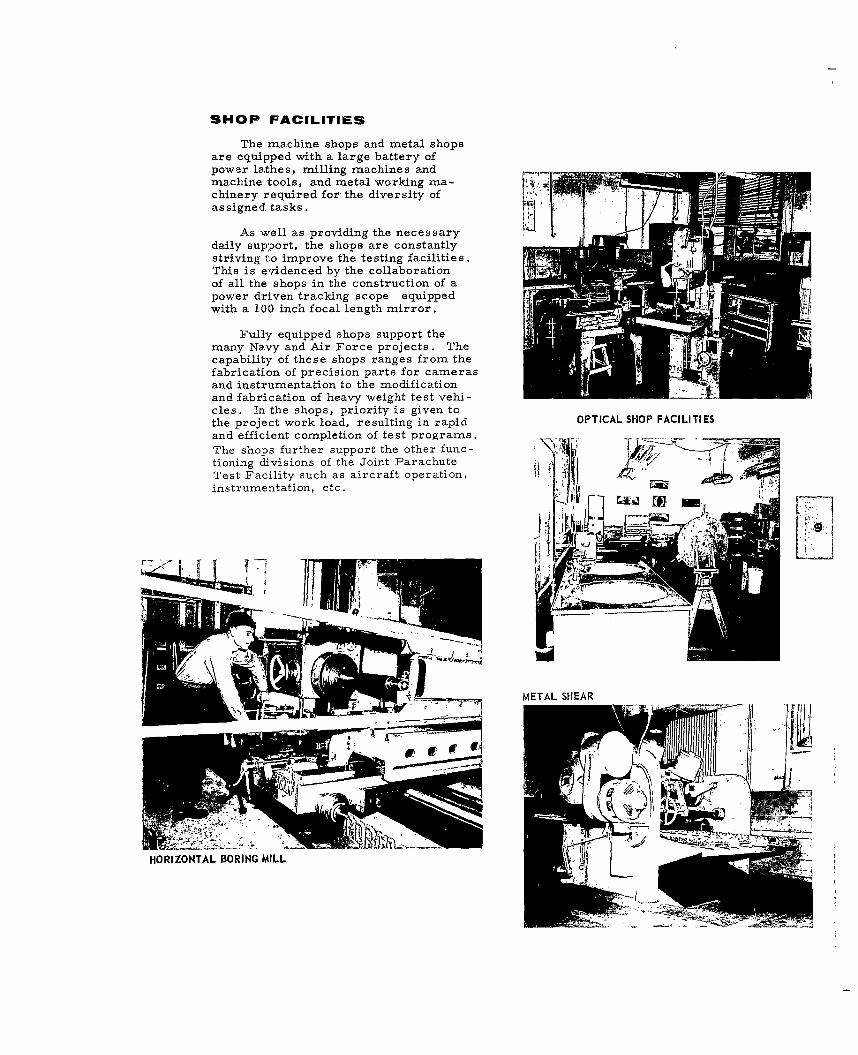
SHOP FACILITIES
The machine shops and metal shopsare equipped with a large battery ofpower lathes, milling machines andmachine tools, and metal working ma-chinery required for the diversity of [ I
As well as providing the necessary
daily support, the shops are constantlystriving to improve the testing facilities.This is evidenced by the collaborationof all the shops in the construction of apower driven tracking scope equippedwith a 100 inch focal length mirror.
Fully equipped shops support themany Navy and Air Force projects. Thecapability of these shops ranges from thefabrication of precision parts for camerasand instrumentation to the modificationand fabrication of heavy weight test vehi-cles. In the shops, priority is given tothe project work load, resulting in rapid OPTICAL SHOP FACILITIESand efficient completion of test programs.The shops further support the other func- jT
tioning divisions of the Joint Parachute A I4 :Test Facility such as aircraft operation,instrumentation, etc. NiR
~ _ _ _
METAL SHEAR
HORIZONTAL BORING MILL

DATA REDUCTION7090 computer at Edwards AFB for corn-
The Data Reduction Facility providesý putation of the desired trajectory andthe project engineers with completely oscillation data. The results are thenprocessed data within forty-eight hours electrically transmitted back to El Centroafter a drop test on a routine basis, and for plotting and delivery to the projectwithin twenty-four hours on a priority engineer. A feasibility study is beingbasis. This short time delay between conducted to evaluate application of adrop test and finished test data results medium size digital computer to thein rapid and economical accomplishment space position problem.of test projects.
For the reduction of telemetry data,For the reduction of cinetheodolite the equipment employed includes the
data Telereadex machines are used to Oscar D Oscillograph Reader, the Digitalread the film. The Telecordex machines Converter E, and the Electroplotter E.used in conjunction with these machines This equipment permits one operator toprovide a tabulated readout of the film read oscillograph records, record theangle data and also operate IBM card data in tabulated form and simultaneouslypunch machines to obtain cards with the plot the data in graphic form. An IBMdata in punched form. These IBM cards Card Punch permits storage of data forare transmitted electrically to the IBM subsequent processing, if desired.
BENSON-LEHNER PLOTTER
UE
AUTODIN SYSTEM PACKARD-BELL 250 DIGITAL COMPUTER
"C3 i. vi
++, P I+pp~l-i+I+I + +1
%

BENDIX G-15 DIGITAL COMPUTER
SCANNING CINETHEODOLITE FILMLi
CINETHEODOLITE FILM READER

777. 7"w
64PREPARING FOR PHOTO MISSION
DESERT PHOTOGRAPHIC CREW
PROJECTION PRINTING ROOM
COLOR MOTION PICTURE PROCESSING
4.
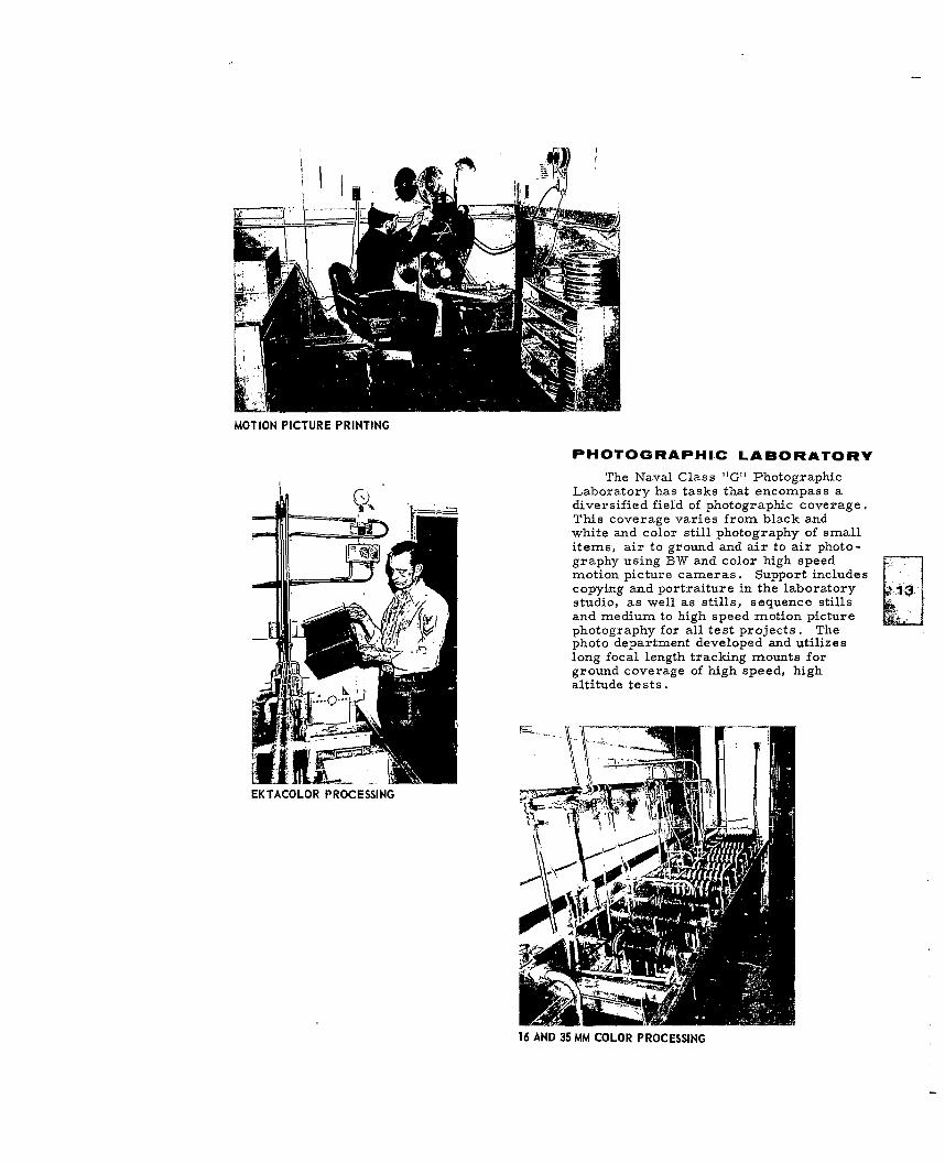
MOTION PICTURE PRINTING
PHOTOGRAPHIC LABORATORY
The Naval Class "G" PhotographicLaboratory has tasks that encompass adiversified field of photographic coverage.This coverage varies from black andwhite and color still photography of smallitems, air to ground and air to air photo-graphy using BW and color high speedmotion picture cameras. Support includescopying and portraiture in the laboratorystudio, as well as stills, sequence stillsand medium to high speed motion pictureSphotography for all test projects. Thephoto department developed and utilizeslong focal length tracking mounts forground coverage of high speed, highaltitude tests.
EKTACOLOR PROCESSING 1
16 AND 35 MM COLOR PROCESSING
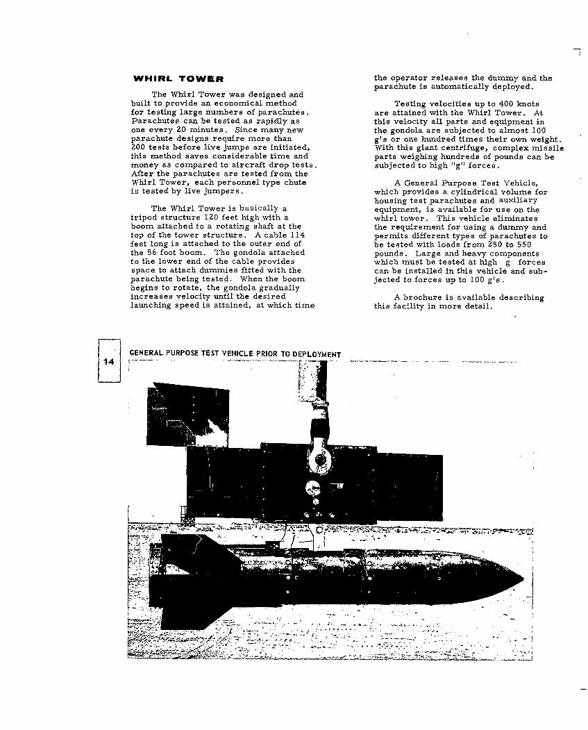
WHIRL TOWER the operator releases the dummy and theparachute is automatically deployed.
The Whirl Tower was designed andbuilt to provide an economical method Testing velocities up to 400 knotsfor testing large numbers of parachutes. are attained with the Whirl Tower. AtParachutes can be tested as rapidly as this velocity all parts and equipment inone every 20 minutes. Since many new the gondola are subjected to almost 100parachute designs require more than g's or one hundred times their own weight.200 tests before live jumps are initiated, With this giant centrifuge, complex missilethis method saves considerable time and parts weighing hundreds of pounds can bemoney as compared to aircraft drop tests, subjected to high "g" forces.After the parachutes are tested from theWhirl Tower, each personnel type chute A General Purpose Test Vehicle,is tested by live jumpers. which provides a cylindrical volume for
housing test parachutes and auxiliaryThe Whirl Tower is basically a equipment, is available for use on the
tripod structure 120 feet high with a whirl tower. This vehicle eliminatesboom attached to a rotating shaft at the the requirement for using a dummy andtop of the tower structure. A cable 114 permits different types of parachutes tofeet long is attached to the outer end of be tested with loads from 250 to 550the 56 foot boom. The gondola attached pounds. Large and heavy componentsto the lower end of the cable provides which must be tested at high g forcesspace to attach dummies fitted with the can be installed in this vehicle and sub-parachute being tested. When the boom jected to forces up to 100 g's.begins to rotate, the gondola graduallyincreases velocity until the desired A brochure is available describinglaunching speed is attained, at which time this facility in more detail.
GENERAL PURPOSE TEST VEHICLE PRIOR TO DEPLOYMENT
~-Z-

TESTING -A PARACHUTE FROM THE WHIRL TOWER
WHIRL TOWER CONTROLS " -
15,'
DUMMY IS RIGGED FOR TELEMETRY AND INSTALLED IN GONDOLA
... . . . .<
I P II
Wi
1i ism
16
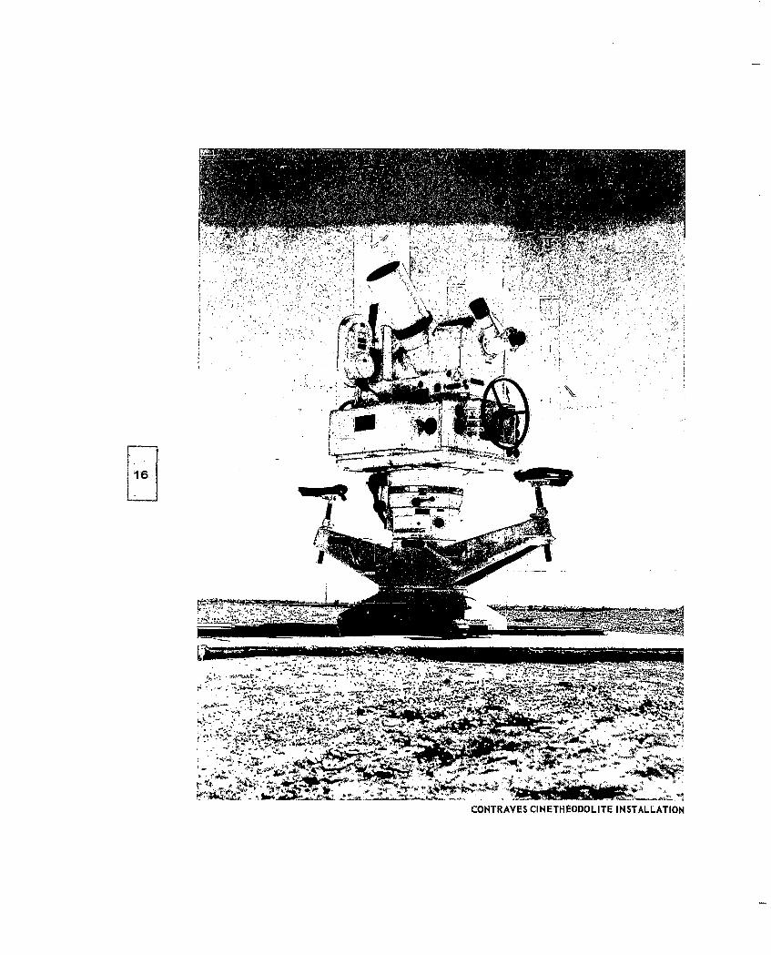
CONTRAVES CINETHEODOLITE INSTALLATION

SPACE POSITHONING RANGE
The El Centro Space PositioningRange consists of two drop zones. Bothdrop zones are radar controlled and"equipped with cinetheodolites for spacepositioning and telescopic trackingcameras to insure complete photographiccoverage of the test item from the momentof release to impact. The cinetheodolitesare radio controlled from the mastertiming station which transmits the shutterpulse, flash pulse, time of day code andbinary frame count code. The TATU
-- _ land drop zone is located approximately"9 miles northwest of El Centro NAF.The San Felipe water drop zone is located
SURVEILLANCE RADAR in the Salton Sea about 30 miles north ofNAF.
E1A1
SPACE POSITIONING RADAR

HIGH SPEED CAMERA WITH TELEPHOTO LENS TRACKING WITH THE ASKANIA KTH 53
ý2 : ii
RADAR VECTORS AIRCRAFT TO RELEASE POINT
.. .

TYPICAL CINETHEODOLITE STATION
RADAR SITE
SALTO SEA FA ILIIE
INTUMN LABOATOR
I~ T
INSTRUMENTT LABORATORY
,,m M
A ll _ __
~,-~-' g

TESTING PERSONNEL RETREIVERTESTING
Personnel parachutes and relatedaccessories are tested extensively toinsure reliable and safe operation. Be-
-__-fore a personnel parachute can be con-sidered safe for live-jumping, it is drop-tested hundreds of times at various alti-tudes, speeds and suspended load con-ditions using dummies in place of men.After successfully completing the dummy"drops the test parachute is live-jumpedseveral hundred times by experienced
J1 test jumpers.
.... . . .. t Besides the testing of parachutes, atetjumper is often required to test such
related equipment as ejection seat sys-tems, survival kits, exposure. suits andmethods of aircraft exit. The primaryaircraft used for dummy tests and livejumps are the B-66, C-130, H-LI, C-47,A3A, Parachutes have been successfullytested at speeds of 40 to 550 knots and ataltitudes of 200 to 40,000 feet.
1J '
TESTING MODEL 'B' EJECTION SEAT

A;,~ 4
.. .....
~A 4
4~Sw-
4,,
00
TEST JUMPERS
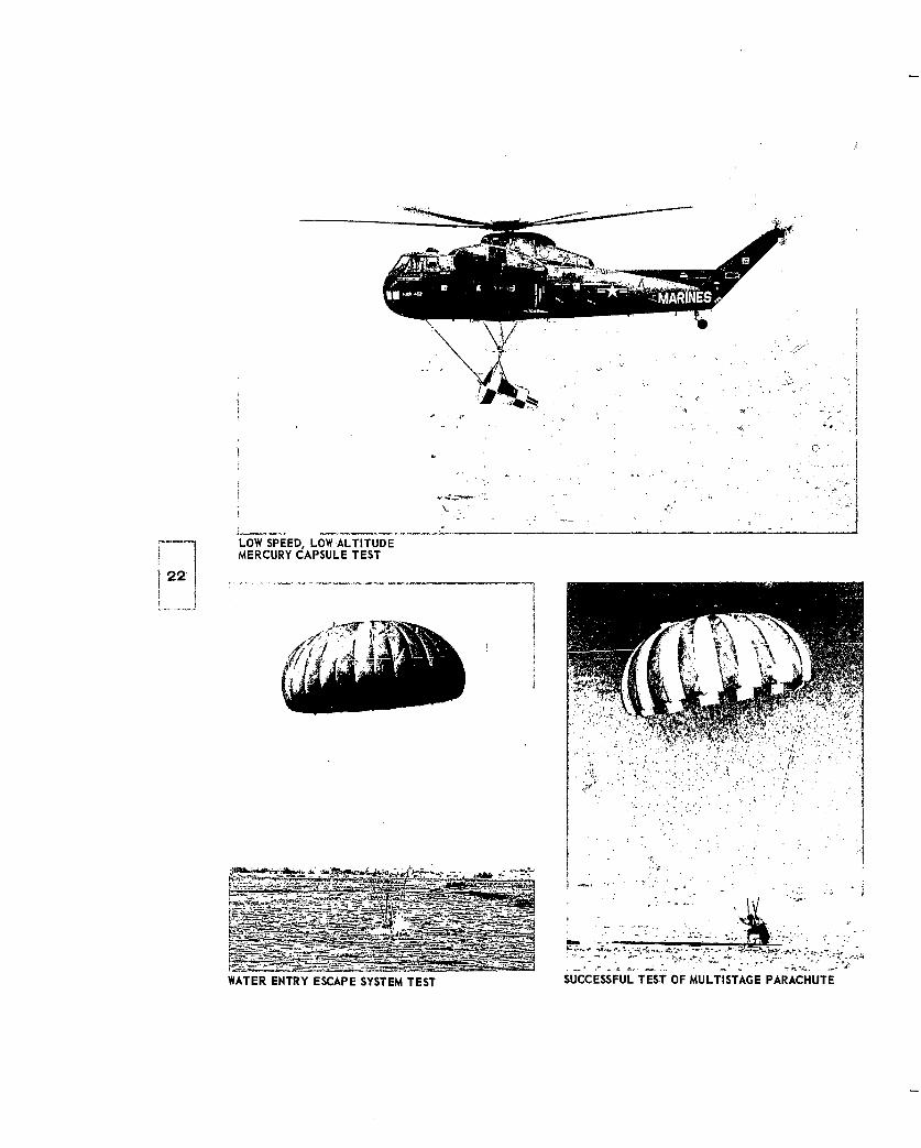
LOW SPEED, LOW ALTITUDEMERCURY CAPSULE TEST
~22'
4t~49
WATER ENTRY ESCAPE SYSTEM TEST SUCCESSFUL TET OF MULTISTAGE PARACHUTE

Recovery systems for many missiles,drones,' escape capsules and satellitesare tested to insure that these items arerecovered successfully under actual con-ditions. Tests of deceleration chuteshave been made in excess of Mach 2.0by rocket boosted vehicles. Final descentparachutes singly or in clusters have beentested with weight ranges from 500 poundsto 12, 500 pounds, airspeeds of 25 knotsIAS to 550 knots JAS and altitudes rang-ing from 400 feet to 50, 000 feet. Fullscale models of missile nose cones,drones, escape capsules and satelliteshave been dropped from aircraft to testthe complete stabilization, recoveryand landing shock attenuation systems.
A 2
RECOVERY TEST OF MERCURY CAPSULE
LIVE TESTING OF AN EJECTION SEAT
NA% A..
KA 57e

I-A t
GEMINI BOILER PLATE MOCKUP BEING PREPARED FOR DROP
SUPERSONIC II VEHICLE BEING DEVELOPED TO TEST HIGH SPEED PARACHUTES

CREE MISSILE IN B-47 WILL TEST HIGH MACH PARACHUTES
LOADING SPECIAL CAPSULE IN B-66 AAIRCARFT

777
26
C-130 DROPS 25,000 POUNDS - AN ANTI TANK GUN AND YA TON TRUCK
The testing and evaluation of cargoparachutes, aircraft installation, railguidance systems and related componentsis another phase of the testing performedby the Joint Parachute Test Facility.Development testing is currently in pro-gress to increase the present standard25, 000-lb. maximum single unit loaddrop capability on the C-130 cargo air-craft for the support of future space,missile and Army type programs. Amaximum of 41,740 pounds has beensuccessfully extracted from a C-130aircraft to date. Tests are presentlybeing conducted on an Air Force andArmy supported program for final evalua-tion of an 108-inch width restraint andrelease guide rail system, with two typesof semi-expendable platforms. The testswill simulate dropping a new type Armyvehicle with a maximum weight of 35, 000pounds.

~ 27SUCCESSFUL RECOVERY OF 16, 000 POUND BUCKET LOADER
SUCCESSFUL RECOVERY OF 105 MM HOWITZER WITH TRUCK AND TRAILER
/ I
.%4
7

SOME OF THE AIRCRAFT UTILIZED BY THE NAVY AND AIR FORCE FOR TESTING PURPOSES
- - - -I

AIRCRAFT PERFORMANCE
Maximum Drop Speed(Level)Max. Drop Max. Single Min. Drop 5,000 z0,000 Max.
Aircraft Altitude Drop Weight Speed Ft. Alt. Ft. Alt. Alt.Ft. Lb. KIAS KIAS KIAS KIAS
C-130 40,000 35,000 105 150 150 130F-100 45,000 3,500 190 550 460 275F-106 DROP CAPABILITY AWAITING MODIFICATIONB-47 45,000 20,000 160 310 310 220B-52D 54, 800 50,000 136 300 300 300B-57 50,000 4,000 IZ0 500 380 180B-66 45,000 12,000 150 550 420 Z25U-Z CLASSIFIED 1, 000 CLASSIFIED CLASSIFIED CLASSIFIEDT-28
(PHOTO) 20,000 - 70 z00 145 145T-33
(PHOTO)42, 000 - 130 430 335 220(DROP) 40,000 1,000 130 390 300 220
H-21 10,000 3,500 0 100 - 100C-47H 15,000 300 90 150 - 110AlE 30,000 Z, 000 100 220 180 140A3A 45,000 1Z, 000 150 550 420 225TF1OB 40,000 Z, 000 115 375 300 225TF9J* 4Z, 000 1,200 130 460 365 230A4A 40,000 3,500 130 560 510 330
Has in-flight ejection seat test capability.

EL CENTRO PARACHUTE RANGE TECHNICAL DATA
Range Capabiliy
Ground-launched Vehicle (Basic Guidance) - Altitude 150, 000 feet - Mach 5.0
Air-launched Boosted Vehicle - Altitude 80,000 feet - Mach 3.0
Range Instrumentation
Radar Space Positioning SystemsCinetheodolites (to 30 frames per second)Telescopic camerasT/M Receiving stations (fixed and mobile)Radio communications (UHF, VHF, FM)Surveillance Radar
Test Vehicle Instrumentation
FM/FM telemetryMechanical tensiometersAttitude and oscillation sensors
Photography
Ground-to-airAir -to-airPlane -to- airVehicle -to -air
Parachute Handling
Drying, repair and fabrication to Z00-feet diameter
Runway
9, 500 feet, hard surface, lighted, -42' elevation
Data Processing
Boscar N cinetheodolite film readerTelereadex cinetheodolite film readers and associated card punch equipment
(punches, sorters, and listing)G-1 5 Digital Computing SystemPackard Bell 250 ComputerElecom 125 Digital ComputerOscar IIElectronic Associates Plotter No 3300

Test VehiclesWeight Max
range TG10 Maxe. Parachute
Vehicle mnn. max. load speed Diameter compartmentlb. lb. in. cu. ft.
Weight Bomb Tewt Vehicles
General Purpose 500 200 1000 15 150 k-t 14 None
General Purpose 1000 500 3000 10 150 kt 18.5 None
General Purpose 2000 2500 5000 8 150 kt 23 None
Light Case 4000 4000 10000 5 150 kt 35 None
Cylindrical Te:t Vehicles
General Purpose 500 400 750 20 500 Rt 14 3.8
General Purpose 1000 650 2400 Zo 500 Ikt 18.5 9.3
General Purpose 2000 1500 4000 15 500 Ict 23 17.7
Light Case 4000 4000 10000 10 500 kt 35 53.3
T-10 7000 36000 7 290 k<t (B-47) 37.5 60.0570 I-t (B-66)
Transonic Tex t Vehicles '2m
Mark 83 800 1500 25 M 1 _1 14 2.3
Transonic III 2000 6000 10 M 1 _ 0 Z4.5 7.0
Supersonic Tes7-t Vehicles
Rocket Boosted Bomb 2250* 2350 10 M 1 - 5 22.2 x 32.4 (aft)14,0 (forward)
Cree Missile 2390* Z350* 60 M z 0 9
(3 missiles)
Supersonic II 2200* 3200* 30 M_ 20 18 1.0
Supersonic III** 2000 5000 25 M 3 0 25 4.0
* The weight indicated is totall aunch xreight.* Supersonic III test vehicle ia 1=sthe fi-mal design stage.