umb protocol 1 - lufft
TRANSCRIPT

UMB Protocol 1.0
Universal Measurement Bus
Communication Protocol
for Meteorological Sensors
Status 03.05.2021
Protocol Version 1.0
Document Version 1.7

2
Datei: UMB-Protokoll_1-0_ENG.docx, Version 1., Status 03.05.2021
Table of Contents 1 Version History ............................................................................................................. 4
2 Preliminary Remarks .................................................................................................... 6 2.1 Restricted Guarantee .............................................................................................. 6 2.2 Nomenclature .......................................................................................................... 6 2.3 Data Format and Byte Order in the Communication Protocol: ................................. 6 2.4 Physical Connection and Hardware Structure ......................................................... 6 2.5 Software Protocol .................................................................................................... 6
3 UMB Binary Protocol (Version 1.0) ............................................................................. 7 3.1 Protocol Stack (Framing) ......................................................................................... 7
3.1.1 (7) Application Layer ........................................................................................ 7 3.1.2 (6) Presentation Layer ...................................................................................... 7 3.1.3 (5) Session Layer ............................................................................................. 7 3.1.4 (4) Transport Layer .......................................................................................... 7 3.1.5 (3) Network Layer ............................................................................................. 7 3.1.6 (2b) Data-Link Layer / Logical Link Control ....................................................... 8 3.1.7 (2a) Data Link Layer Media Access Control ..................................................... 8 3.1.8 (1) Physical Layer ............................................................................................ 9 3.1.9 Summary .......................................................................................................... 9
3.2 Topology ................................................................................................................10 3.3 Addressing with Class- and Device-ID....................................................................11
3.3.1 Examples for the Creation of Addresses .........................................................11 3.4 CRC Checksum .....................................................................................................12 3.5 Data Types .............................................................................................................12 3.6 Measurement Value Types .....................................................................................12 3.7 Status and Error Codes ..........................................................................................13 3.8 Commands (Datagrams) ........................................................................................15
3.8.1 Summary of Commands ..................................................................................15 3.8.2 Hardware and Software Version (20h) ............................................................16 3.8.3 Device Information (2Dh) ................................................................................16 3.8.4 Read Out EEPROM (21h) ...............................................................................17 3.8.5 Program EEPROM (22h) .................................................................................17 3.8.6 Program EEPROM with PIN (F0h) ..................................................................18 3.8.7 Online Data Request (23h) ..............................................................................18 3.8.8 Multi-Channel Online Data Request (2Fh) .......................................................19 3.8.9 Offline Data Request (24h) ..............................................................................20 3.8.10 Reset / Default (25h) .......................................................................................21 3.8.11 Reset with Delay (2Eh) ....................................................................................21 3.8.12 Status Request (26h) ......................................................................................21 3.8.13 Last Error Message (2Ch) ...............................................................................22 3.8.14 Set Time / Date (27h) ......................................................................................22 3.8.15 Readout Time / Date (28h) ..............................................................................22 3.8.16 Test / Calibration Command (29h) ...................................................................23 3.8.17 Monitor (2Ah) ..................................................................................................23 3.8.18 Protocol Change (2Bh) ....................................................................................24 3.8.19 Set New Device ID (30h) .................................................................................24 3.8.20 UMB-Tunnel (36h) ...........................................................................................25 3.8.21 Firmware update (37h) ....................................................................................26 3.8.22 Transmission of Binary Data (38h) ..................................................................27
3.9 Channel Assignment ..............................................................................................29 3.9.1 Channel Assignment – General Allocation ......................................................29

3
Datei: UMB-Protokoll_1-0_ENG.docx, Version 1., Status 03.05.2021
3.9.2 TLS Channel Assignment ................................................................................29 3.10 Units List ................................................................................................................30
3.10.1 Temperature ...................................................................................................30 3.10.2 Humidity ..........................................................................................................30 3.10.3 Lengths ...........................................................................................................30 3.10.4 Velocities .........................................................................................................30 3.10.5 Electrical Variables ..........................................................................................30 3.10.6 Frequency .......................................................................................................31 3.10.7 Pressure ..........................................................................................................31 3.10.8 Volumes ..........................................................................................................31 3.10.9 Time ................................................................................................................31 3.10.10 Precipitation .................................................................................................31 3.10.11 Miscellaneous ..............................................................................................32
3.11 Example of a Binary Protocol Request ...................................................................33 3.12 Comments on broadcast messages .......................................................................34
4 Appendix ......................................................................................................................35 4.1 CRC Calculation .....................................................................................................35
4.1.1 Example of a CRC-CCITT Calculation in C .....................................................35 4.2 Automatic Readout of a Network ............................................................................37
4.2.1 Background .....................................................................................................37 4.2.2 Necessary ID Configuration of the Sensors .....................................................37 4.2.3 Scanning the Network .....................................................................................37
4.3 Data Types in UMB Products per TLS2002 FG3 ....................................................38 4.3.1 Example of a TLS Measurement Value Request .............................................38 4.3.2 Supported TLS-DE Types FG3 .......................................................................38 4.3.3 Derived variables ............................................................................................39 4.3.4 DE Type 70 “Road Surface Condition” (RSC)..................................................39 4.3.5 DE Type 71 “Precipitation Type” (PT) ..............................................................40 4.3.6 DE Type 140 “Door Contact” (DC) ...................................................................41 4.3.7 DE Type 140 Inverted “Door Contact” (DC) .....................................................41
4.4 Strings and Character encoding .............................................................................42 4.4.1 Character arrays .............................................................................................42 4.4.2 ASCII-Encoding ...............................................................................................42

4
Datei: UMB-Protokoll_1-0_ENG.docx, Version 1., Status 03.05.2021
1 Version History
Document Version
Date Compiled by
Description of Amendment
0.0 24.11.2004 SR Compilation
0.1 14.06.2005 EES First edition
0.2 22.12.2005 EES Update 2 wire interface hardware
0.3 07.02.2006 EES Renaming to UMB, supplement “Automatic Readout of a Network” and device information
0.4 07.03.2006 EES Nomenclature amended; BC command summary amended
0.5 09.03.2006 EES - Device information command extended by addition of E2 variable and details of the type of information in the answer
- Channel assignment extended by relative measurement values
0.6 04.04.2006 EES List of units amended
1.0 12.04.2006 EES - Measurement value types amended
- Device information command extended by addition of measurement value type
First approved version
1.1 19.05.2006 EES - Status byte inserted in the answer of Readout Time/Date (28h) command
SR - Status 29h under-voltage defined
EES - Channel assignment per device class amended
- Amendments to TLS coding in the channel assignment and the list of supported DE types per FG3 in the appendix
- Logo included
1.2 18.07.2006 EES - Status 2Ah hardware fault defined
- Status 2Bh fault in the measurement defined
- List of units amended (l/m²)
- ASCII character set amended
- Measurement value type ‘Sum’ 14h defined
BEL - RRS integrated
EES - Status 52h Channel over-range defined
- Status 53h Channel under-range defined
- List of units amended (hPa hectopascals)
BEL - Types of precipitation defined in accordance with the WMO on RRS channel 700
EES - General channel assignment 10500 defined for pulses and 2000 for further TLS channels
- Measurement value type 15h defined for ‘vectoral mean value’
- TLS channels for ANACON amended (LD and 2nd channel)
- Status codes for calibration amended
- Change in the answer to the TLS channel request (adaptation to existing implementation)

5
Datei: UMB-Protokoll_1-0_ENG.docx, Version 1., Status 03.05.2021
1.3 08.08.2006 EES - Response time of the calibration command (29h) changed from short to long
- Status code 36h changed to ‘Channel deactivated’
- Data type of the TLS channels adapted in the general channel assignment of the device classes
- Channel Assignment Chapter moved back to later in document
- Response time for online data request (23h) changed to ‘long’ due to computing-intensive channels (e.g. ANACON)
- Instructions for ‘Multi-Channel Online Data Request’ (2Fh) amended in relation to long response times
- ANACON TLS channel DE type 66 TPT dewpoint amended
- Various channel assignments amended
- Command 29h renamed ‘test command’ as this is used not only for adjustment but also to test various device functions
1.4 12.09.2006 EES - Comment expanded to state that no TLS channels are available in the ASCII protocol
SR - Road sensor channel assignment
- Mil length unit added
1.5 14.12.2007 EES - ‘Set new id’ command vers. 1.1 amended
- Info added to status code 28h
- Knots unit added
BEL - Non-metric units inch and mil / inch/h and mil/h added on R2S channels (chapters 3.9.3, 3.10.3 and 3.10.9)
EES
- Channel list added for ANACON-UMB (abs. humidity and pressure) - Device class and channel list added for compact weather station
- Product list amended
- Channel assignment device class 6 universal measurement transmitter for precipitation and pulses amended
1.6 17.12.2010 EES - Product designations for the compact weather station amended
- Error code INIT_ERROR (2Ch) = Error on device initialization and OS_ERROR (2Dh) = Error in operating system added
- Channel designations for absolute and relative air pressure amended
- Error code
1.7 03.05.2021 RZ - IRS31Pro-UMB added
KRM - Firmware update command (37h) added
- MARWIS-UMB supported commands
RZF - UMB-Tunnel command (36h) added
- corrected layer definition
- corrected description of online data request (2Fh)
- corrected description of broadcast
- removed UMB-ASCII
- definition of UMB-ASCII2.0 as separate document
KRM Reset subcommand 0x14 specified
RZF - added UMB binary data command (38h)
KRM - documentation of UMB error CALC_ERROR
KRM - documentation of device specific version information command
RZF <status> added to command descriptions
BR Added new TLS-Channels

6
Datei: UMB-Protokoll_1-0_ENG.docx, Version 1., Status 03.05.2021
2 Preliminary Remarks
The protocols described here were developed for meteorological sensors and facilitate simplified communication with various devices such as IRS31-UMB, VS20-UMB and R2S-UMB.
2.1 Restricted Guarantee The methods and settings described in this document allow device configuration exceeding the standard (ConfigTool.NET). The selection of incorrect settings can lead to the loss of the specified measurement accuracy and to device failure. OTT HydroMet reserves the right to restrict the guarantee to the products in the case of the application of the procedures described here.
2.2 Nomenclature Device: The term “device” is used in this document as a synonym for the equipment family of meteorological sensors such as IRS31, VS20 and R2S.
Hexadecimal values are identified by the suffix ‘h’. Decimal values are identified by the suffix ‘d’.
‘BC’ identifies commands which can be transmitted by broadcast. ‘NBC’ stands for ‘not broadcast-able’ (please also see Comments on broadcast on page 34).
2.3 Data Format and Byte Order in the Communication Protocol: LONG: LowLowByte LowHighByte HighLowByte HighHighByte INT: LowByte HighByte FLOAT: Per IEEE format (4 bytes) DOUBLE: Per IEEE format (8 bytes)
2.4 Physical Connection and Hardware Structure Usually the devices in a network are controlled via a half-duplex RS485 2 wire interface. The ISOCON additionally provides an RS232 interface. The factory-set baud rate is 19200 Baud with 8 data bits, one stop bit and no parity (8N1). Alternatively, messages can also be exchanged over TCP sockets or similar. In this case the connection to the sensor is established by an IP to serial adapter or, if supported by the sensor, directly through Ethernet of Wi-Fi. Port numbers for IP access can be found in the sensor manual.
2.5 Software Protocol Configuration and polling of the device takes place in binary protocol. As the system operates without collision detection, the controller-device principle is strictly observed, i.e. a transaction is always initiated by the controller.
Alternatively, the human readable protocol UMB-ASCII 2.0 is provided (although not all products currently support this feature). Please see the separate manual for UMB-ASCII 2.0.

7
Datei: UMB-Protokoll_1-0_ENG.docx, Version 1., Status 03.05.2021
3 UMB Binary Protocol (Version 1.0)
The OSI (Open Systems Interconnection) reference model of the International Standards Organization (ISO) can be used to abstract the logical steps of the header construction.
The datagrams pass through the individual layers of the protocol stack and in doing so are progressively provided with the header data. In this way a frame is created, the maximum length of which is limited to 255 bytes. 210 bytes are available for reference data.
3.1 Protocol Stack (Framing)
3.1.1 (7) Application Layer
The application layer is not directly part of the UMB protocol and is represented by the programs or functions using the UMB protocol respectively execute the transmitted commands. Examples are UMB ConfigTool.NET on the controller side and, on device side the functions provided for the acquisition of sensor measurement values.
3.1.2 (6) Presentation Layer
A command consists of a minimum of two characters: The command <cmd> and the version number of the command <verc>. The optional payload may contain up to 210 characters. The value range of one byte of the payload is 0 to 255. Response telegrams include the status byte in the payload
1 2 3 - 4 5 - 6 7 8 9 10 11 ... (8 + len) optional
9 + len 10 + len 11 + len
12 + len
<cmd> <verc> <payload>
3.1.3 (5) Session Layer
The session layer is not defined for the UMB protocol and therefore transparent.
3.1.4 (4) Transport Layer
The transport layer is not defined for the UMB protocol and therefore transparent.
3.1.5 (3) Network Layer
Addressing is performed by 16-bit addresses. Within the network layer the command and payload data received from the higher layer are provided with receiver (<to> and transmitter <from> addresses.
1 2 3 - 4 5 - 6 7 8 9 10 11 ... (8 + len) optional
9 + len 10 + len 11 + len
12 + len
<to> <from>
8
Datei: UMB-Protokoll_1-0_ENG.docx, Version 1., Status 03.05.2021
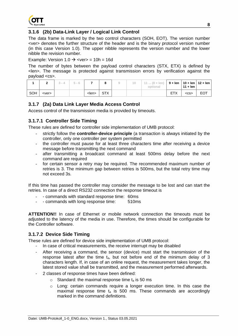
3.1.6 (2b) Data-Link Layer / Logical Link Control
The data frame is marked by the two control characters (SOH, EOT). The version number <ver> denotes the further structure of the header and is the binary protocol version number (in this case Version 1.0). The upper nibble represents the version number and the lower nibble the revision number.
Example: Version 1.0 → <ver> = 10h = 16d
The number of bytes between the payload control characters (STX, ETX) is defined by <len>. The message is protected against transmission errors by verification against the payload <cs>.
1 2 3 - 4 5 - 6 7 8 9 10 11 ... (8 + len) optional
9 + len 10 + len 11 + len
12 + len
SOH <ver> <len> STX ETX <cs> EOT
3.1.7 (2a) Data Link Layer Media Access Control
Access control of the transmission media is provided by timeouts.
3.1.7.1 Controller Side Timing
These rules are defined for controller side implementation of UMB protocol:
- strictly follow the controller-device principle (a transaction is always initiated by the controller, only one controller per system permitted
- the controller must pause for at least three characters time after receiving a device message before transmitting the next command
- after transmitting a broadcast command at least 500ms delay before the next command are required
- for certain sensor a retry may be required. The recommended maximum number of retries is 3. The minimum gap between retries is 500ms, but the total retry time may not exceed 3s.
If this time has passed the controller may consider the message to be lost and can start the retries. In case of a direct RS232 connection the response timeout is
- - commands with standard response time: 60ms - - commands with long response time: 510ms
ATTENTION!! In case of Ethernet or mobile network connection the timeouts must be adjusted to the latency of the media in use. Therefore, the times should be configurable for the Controller software.
3.1.7.2 Device Side Timing
These rules are defined for device side implementation of UMB protocol: - In case of critical measurements, the receive interrupt may be disabled
- After receiving a command, the sensor (device) must start the transmission of the response latest after the time ta, but not before end of the minimum delay of 3 characters length. If, in case of an online request, the measurement takes longer, the latest stored value shall be transmitted, and the measurement performed afterwards.
- 2 classes of response times have been defined:
o Standard: the maximal response time ta is 50 ms
o Long: certain commands require a longer execution time. In this case the maximal response time ta is 500 ms. These commands are accordingly marked in the command definitions.

9
Datei: UMB-Protokoll_1-0_ENG.docx, Version 1., Status 03.05.2021
- If the command exceeds the maximal response time the device must suppress the transmission of the response. The controller will not get a response, but this doesn’t give definite information if the command has been executed or not. It would be possible that the maximal response time was exceeded together with the completion of the command. This means that in any case the command must be repeated by the controller. (in case of procedures including sequences of commands it may even require terminating the procedure and restart it)
3.1.8 (1) Physical Layer
The physical medium is not part of the UMB protocol definition and basically free of choice. Usually 2 wire RS485 is used, with standard baud rate 19200 Baud, 8 data bits, 1 stop bit and no parity.
Additionally, UMB telegrams may be tunneled through other communication media, e.g. Ethernet, Wi-Fi, or Bluetooth.
3.1.9 Summary
The complete request frame is illustrated here in summary:
1 2 3 - 4 5 - 6 7 8 9 10 11 ... (8 + len) optional
9 + len 10 + len 11 + len
12 + len
SOH <ver> <to> <from> <len> STX <cmd> <verc> <payload> ETX <cs> EOT
Response Frame:
1 2 3 - 4 5 - 6 7 8 9 10 11 12 ... (9 + len) optional
10 + len 11 + len 12 + len
13 + len
SOH <ver> <to> <from> <len> STX <cmd> <verc> <status> <payload> ETX <cs> EOT
SOH Control character for the start of a frame (01h) 1 byte
<ver> Header version number, e.g.: V 1.0 → <ver> = 10h = 16d; 1 byte
<to> Receiver address, 2 bytes
<from> Transmitter address, 2 bytes
<len> Number of data bytes between STX and ETX; 1 byte
STX Control character for the start of the user data transmission (02h); 1 byte
<cmd> Command; 1 byte
<verc> Version number of the command; 1 byte
<payload> Data bytes; 0 – 210 bytes
ETX Control character for the end of the user data transmission (03h); 1 byte
<cs> Checksum, 16 -bit CRC; 2 bytes
EOT Control character for the end of the frame (04h); 1 byte
Control characters: SOH (01h), STX (02h), ETX (03h), EOT (04h).
1. Controller-Request
Device-Response
max. ta
min. 3 chars
2. Controller-Request
min. 3 chars

10
Datei: UMB-Protokoll_1-0_ENG.docx, Version 1., Status 03.05.2021
3.2 Topology A sensor network is constructed as follows:
Controller: The controller is connected to the RS232 interface built into the ISO converter. An interface module for USB and Ethernet via virtual COM port is also available as an option.
Sensor: The sensors are connected via a 2-wire connection plus power supply lines through one ISO converter each; the converter also provides the power supply for the sensor.
ISO Converter: The converters are connected by stackable plug-in connectors which can be arranged in sequence. To cover larger distances between ISO converters, they may be connected RS485 interface to RS485 interface.
Sensors from other Manufacturers
If sensors from other manufacturers also operate in accordance to the controller/device principle, they may be connected to the RS232 interface of an ISO converter; it is also conceivable that sensors with RS422/485/2 wire/4 wire could be connected to the measurement network via a suitable converter (e.g. Phoenix).
Measurement Modules
Intelligent measurement modules, which make the analogue signals available on the bus, are available for sensors without a data interface (e.g. 0 – 1V or 4 – 20mA).
ISO
Co
nve
rte
r
ISO
Co
nve
rte
r
ISO
Co
nve
rte
r UMB
Sensor UMB
Sensor UMB
Sensor
Controller (e.g. PC)
ISO
Co
nve
rte
r
ISO
Co
nve
rte
r
RS232 Sensor /
Converter Power supply
unit Power supply
unit
2 wire cable up to 1200 m →
2 wire cable plus power supply
2 wire cable plus power supply
RS232 RS232 optional USB / Ethernet
AN
AC
ON
Analogue Signal
US
B / E
thern
et

11
Datei: UMB-Protokoll_1-0_ENG.docx, Version 1., Status 03.05.2021
3.3 Addressing with Class- and Device-ID Addressing takes place by means of a 16-bit address. This is divided into a sensor class ID and a device ID.
Address (2 bytes = 16 bits)
Bits 15 – 12 (upper 4 bits) Bits 11 – 8 (middle 4 bits)
Bits 7 – 0 (lower 8 bits)
Class ID (0 to 15) Reserved Device ID (0 – 255)
0 Broadcast
For internal usage only,
usually 0
0 Broadcast
1 Road sensor (IRS31-UMB) 1 - 255 available
2 Rain sensor (R2S-UMB)
3 Visibility sensor (VSx-UMB)
4 Active road sensor (ARS31-UMB)
5 Non-invasive road sensor (NIRS31-UMB)
6 Universal measurement transmitter (ANACON)
7 Compact weather station (WSx-UMB)
8 Wind sensor (VENTUS / V200A)
9 Road sensor (IRS31Pro-UMB)
10 Non-invasive mobile road sensor (MARWIS-UMB)
11 Snow depth sensor (SHM)
Class ID (12 to 14) Subclass-ID
12 Cloud Height Simulator 0
Reserved for additions t.b.d
13 div. protocol convertors t.b.d
14 Reserved for additions t.b.d
Class ID (15) Reserved
15 Controller / control devices Must be 0
ID = 0 is designated as broadcast for both classes and devices. This makes it possible to send a broadcast on a specific class. When a global broadcast is sent class and device ID must be 0.
3.3.1 Examples for the Creation of Addresses
If, for example, a road sensor is to be addressed with the device ID 3, this is achieved as follows:
Class ID for the road sensor is 1 = 1h Device ID is 3 = 3h
Placing the class and device ID’s together gives the 1003h = 4099d.
Further examples:
Class ID Device ID Address Explanation
3h 1h (1d)
3001h (12289d)
Visibility sensor with device ID 1
0h
000h (0000d)
0000h (0d)
Broadcast to all devices and sensors
1h
000h (0000d)
1000h (4096d)
Broadcast to all road sensors

12
Datei: UMB-Protokoll_1-0_ENG.docx, Version 1., Status 03.05.2021
3.4 CRC Checksum The CRC16-MCRF4XX checksum is formulated with the following polynomial:
x16 + x12 + x5 + 1 (LSB first mode; start value FFFFh)
The checksum is formulated via all bytes prior to the checksum (1 ... 9 + len), i.e. from SOH to ETX inclusive.
The little-endian byte sequence is applicable to the checksum.
When a device receives a frame with an incorrect CRC, there is no reaction to this command.
Source code examples of a CRC calculation can be found in the Appendix.
3.5 Data Types The following data types are used in this protocol, e.g. for the measurement value request:
<type> Type Name Define Bytes Range
10h (16d) unsigned char UNSIGNED_CHAR 1 0 ... 255
11h (17d) signed char SIGNED_CHAR 1 -128 ... 127
12h (18d) unsigned short UNSIGNED_SHORT 2 0 ... 65.535
13h (19d) signed short SIGNED_SHORT 2 -32.768 ... 32.767
14h (20d) unsigned long UNSIGNED_LONG 4 0 ... 4.294.967.295
15h (21d) signed long SIGNED_LONG 4 -2.147.483.648 ... 2.147.483.647
16h (22d) float FLOAT 4 ±1.18E-38 ... ±3.39E+38 (7 digits)
17h (23d) double DOUBLE 8 ±2.23E-308 ... ±1.79E+308 (15 digits)
Comment: float and double in IEEE format
3.6 Measurement Value Types The following measurement value types are used for the measurement value enquiry:
<type> Type Name Define Description
10h (16d) current MWT_CURRENT Current measurement value
11h (17d) min MWT_MIN Minimum value
12h (18d) max MWT_MAX Maximum value
13h (19d) avg MWT_AVG Mean value
14h (20d) sum MWT_SUM Sum
15h (21d) vct MWT_VCT Vectoral mean value

13
Datei: UMB-Protokoll_1-0_ENG.docx, Version 1., Status 03.05.2021
3.7 Status and Error Codes Each response telegram contains a status byte. This gives information on the success or failure of the command. Further information is transmitted for certain error codes, which makes exact error analysis possible.
An error message is transmitted if a command was not processed successfully. This is constructed as follows:
<cmd><verc><status>,[ <info>n]
If there is no further information about a status, <info>n is omitted. In order that the frame control characters do not appear too often, 01h to 0Ah is dispensed with for these codes.
Codes:
<status> <info> Define Description
00h (0d) OK Command successful; no error; all OK
10h (16d) UNKNOWN_CMD Unknown command; not supported by this device
11h (17d) INVALID_PARAM Invalid parameter
12h (18d) INVALID _HEADER Invalid header version
13h (19d) INVALID _VERC Invalid version of the command
14h (20d) INVALID _PW Invalid password for command
15h (21d) INVALID _WERT Invalid value
20h (32d) READ_ERR Read error
21h (33d) WRITE_ERR Write error
22h (34d) <maxlength> TOO_LONG Length too great; max. permissible length is designated in <maxlength>
23h (35d) INVALID_ADDRESS Invalid address / storage location
24h (36d) <channel>2 (1 INVALID_CHANNEL Invalid channel
25h (37d) INVALID_CMD Command not possible in this mode
26h (38d) UNKNOWN_CAL_CMD Unknown calibration command
27h (39d) CAL_ERROR Calibration error
28h (40d) <channel>2 (2 BUSY Device not ready; e.g. initialization / calibration running
29h (41d) LOW_VOLTAGE Under-voltage
2Ah (42d) HW_ERROR Hardware error
2Bh (43d) MEAS_ERROR Measurement error
2Ch (44d) INIT_ERROR Error on device initialization
2Dh (45d) OS_ERROR Error in operating system
2Eh (46d) COM_ERROR Internal communication error
2Fh (47d) HW_SW_MISMATCH Hardware and software version do not match
(1info <channel>2 only in command ‘Online Data Request’ (2info <channel>2 only in command ‘Online Data Request’
14
Datei: UMB-Protokoll_1-0_ENG.docx, Version 1., Status 03.05.2021
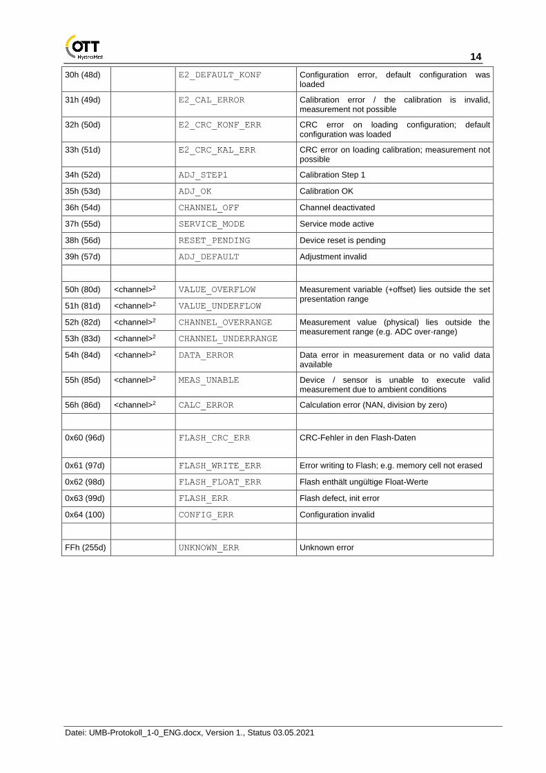
30h (48d) E2_DEFAULT_KONF Configuration error, default configuration was loaded
31h (49d) E2_CAL_ERROR Calibration error / the calibration is invalid, measurement not possible
32h (50d) E2_CRC_KONF_ERR CRC error on loading configuration; default configuration was loaded
33h (51d) E2_CRC_KAL_ERR CRC error on loading calibration; measurement not possible
34h (52d) ADJ_STEP1 Calibration Step 1
35h (53d) ADJ_OK Calibration OK
36h (54d) CHANNEL_OFF Channel deactivated
37h (55d) SERVICE_MODE Service mode active
38h (56d) RESET_PENDING Device reset is pending
39h (57d) ADJ_DEFAULT Adjustment invalid
50h (80d) <channel>2 VALUE_OVERFLOW Measurement variable (+offset) lies outside the set presentation range
51h (81d) <channel>2 VALUE_UNDERFLOW
52h (82d) <channel>2 CHANNEL_OVERRANGE Measurement value (physical) lies outside the measurement range (e.g. ADC over-range)
53h (83d) <channel>2 CHANNEL_UNDERRANGE
54h (84d) <channel>2 DATA_ERROR Data error in measurement data or no valid data available
55h (85d) <channel>2 MEAS_UNABLE Device / sensor is unable to execute valid measurement due to ambient conditions
56h (86d) <channel>2 CALC_ERROR Calculation error (NAN, division by zero)
0x60 (96d)
FLASH_CRC_ERR CRC-Fehler in den Flash-Daten
0x61 (97d) FLASH_WRITE_ERR Error writing to Flash; e.g. memory cell not erased
0x62 (98d) FLASH_FLOAT_ERR Flash enthält ungültige Float-Werte
0x63 (99d) FLASH_ERR Flash defect, init error
0x64 (100) CONFIG_ERR Configuration invalid
FFh (255d) UNKNOWN_ERR Unknown error

15
Datei: UMB-Protokoll_1-0_ENG.docx, Version 1., Status 03.05.2021
3.8 Commands (Datagrams) For reasons of clarity, the following list of commands is limited to the presentation layer. The following short form is used for better presentation:
<cmd><verc>[<payload0>n, <payload1>n, …]
<cmd><verc><status>[<payload0>n, <payload1>n, …]
Hexadecimal values are identified by the suffix ‘h’. Character strings are in double quotation marks and concluded by the null character (00h). The little-endian byte sequence (Intel, low byte first) applies to the transmission of words. Wildcards for syntactic units are identified by angle brackets. If the length of the variable is greater than 1 byte, this is designated ‘n’ in the index.
3.8.1 Summary of Commands
Sorted by <cmd>:
<cmd> Description BC RT
20h Hardware and software version
s
21h Read out EEPROM l
22h Program EEPROM l
23h Online data request l
24h Offline data request s
25h Reset / default ⚫ s/l*
26h Status request S
27h Set time / date ⚫ S
28h Read out time / date S
29h Test command l
2Ah Monitor l
2Bh Protocol change ⚫ s
2Ch Last fault message s
2Dh Device information s
2Eh Reset with delay ⚫ s
2Fh Multi-channel online data request
l
30h Set new device ID permanently (verc 1.0)
⚫ s
30h Set new device ID temporarily (verc 1.1)
⚫ s
36h UMB-Tunnel l
37h Transfer Firmware l
38h Transfer Binary Data l
40h – 7Fh
Reserved for device-specific commands (see device description)
80h – 8Fh
Reserved for development
F0h Program EEPROM with PIN l
RT = response time; s = short; l = long
BC = broadcast-enabled command *depending on sub cmd, see command specification
** request will be answered with “UNBEK_CMD”: <cmd>10h[10h]
ATTENTION!! A device (sensor) only accepts a command if it was sent by a controller (observance of controller-device principle).

16
Datei: UMB-Protokoll_1-0_ENG.docx, Version 1., Status 03.05.2021
3.8.2 Hardware and Software Version (20h)
Command <cmd>: 20h (NBC)
Command version <verc>: 1.0
Data <payload>: none
Description: This command requests the hardware and software version of the addressed device.
Request: 20h10h[ ]
Response: 20h10h<status>[<hardware>, <software>]
Response Time: short
Example: SW-Version 2.3 →<software> = 17h = 23d HW-Version 6 →<hardware> = 06h = 6d
3.8.3 Device Information (2Dh)
Command <cmd>: 2Dh (NBC)
Command version <verc>: 1.0
Data <payload>: <info>, <option>n
Description: This command returns the following device information:
Request: 2Dh10h[<info>, <option>n]
<info> Type of information desired
<option>n Option for further information required
Response: 2Dh10h[<status>, <info>, <answer>]
Response Time: short
<info> <option> Description <Answer>
10h none Device identification <ID>40 e.g. ‘Visibility Sensor VS20’
11h none Device description <desc>40 e.g. ‘Visibility A92 West’
12h none Hardware and software version
<hardware>, <software> Version 2.3 = 17h = 23d
13h none Extended version info <SerNo>², <MMYY>², <Project>², <PartsList>, <CircuitDiagram>, <hardware>, <software>, <e2version>, <DeviceVersion>²
14h none EEPROM size <e2_size>²
15h none No. of channels available
<channels>², <blocks>
16h <block> Numbers of the channels <block>, <channels>, [<channel>²]<channels>
17h none Read number of device specific version information slots
<num-slot-ids>
18h <slot-id> Read device specific version information
<name>40,<major-version>,<minor-version>, <unixtime-date>4,<rc-version>
20h <channel>² Meas. variable of channel
<channel>², <variable>20 e.g. ‘visibility’
21h <channel>² Meas. range of channel <channel>², <min>n, <max>n n *)
22h <channel>² Meas. unit of channel <channel>², <unit>15 e.g. ‘m’
23h <channel>² Data type of channel <channel>², <data_type> e.g. 16h for float
24h <channel>² Meas. value type <channel>², <mv_type> e.g. 13h for mean value
30h <channel>² Complete channel info <channel>², <variable>20, <unit>15, <mv_type>, < data_type >, <min>n, <max>n n *)
40h none Number of IP interfaces <interfaces>
41h <interface> IP Information <interface>, <name>20, <ip>4, <netmask>4, <gateway>4, <dns>4, <link>, <tcp_port>2
n *) The data type of min and max is the same as that of the measurement value. E.g. measurement value float → min, max float

17
Datei: UMB-Protokoll_1-0_ENG.docx, Version 1., Status 03.05.2021
Comment: Not all the device types provide the complete set of information. If an information is not available, the status will be set to “invalid parameter” (11h). <info> and <answer> of the response will be omitted.
All character strings are padded with blanks. There is no ‘\0’ termination!
On a request for the channel numbers (16h), up to 100 channels are consolidated in one block (beginning with block 0). If a sensor has more than 100 channels, there are correspondingly more blocks. The number of blocks is indicated in the request for the number of available channels (15h).
The device specific version information (18h) reports the versions / revisions of separate software modules. If <rc-version> = 0 the installed version is a public release, otherwise a release candidate. As a convention <slot-id> = 0 is reserved for the system software. The build time is formatted as Unix timestamp (UTC time).
On a request for the measurement range of a channel (21h) or the complete channel information (30h), the length n of min and max depends on the data type. (See 3.5 Data Types)
IP addresses, as in info 41h are transmitted as 32bit unsigned value (little endian).
3.8.4 Read Out EEPROM (21h)
Command <cmd>: 21h (NBC)
Command version <verc>: 1.0
Data <payload>: <start>2, <length>
Description: With this command, the transmission of <length> bytes from the storage location <start> of the EEPROM is initiated.
Request: 21h10h[<start>2, <length>]
Response: 21h10h<status>[<start>2, <length>, <data<length>>]
Response time: long
Comment: The maximum number of bytes (<length>) is 200.
In case of error the fields <start>, <length> and <data> are omitted. If the error status is 22h (“TOO_LONG”) one byte with the permitted maximal <length> follows.
3.8.5 Program EEPROM (22h)
Command <cmd>: 22h (NBC)
Command version <verc>: 1.0
Data <payload>: <start>2, <length>, <data><length>
Description: With this command, a data block <data> of length <length> bytes is transmitted to the receiver. This is written to the EEPROM with effect from the address <start>. When all bytes are programmed, the sender of the command is informed about the success of the action by means of an acknowledgement.
Request: 22h10h[<start>2, <length>, <data><length>]
Response: 22h10h<status>[max_length]
Response time: long

18
Datei: UMB-Protokoll_1-0_ENG.docx, Version 1., Status 03.05.2021
Comment: As the device’s maximum response time is limited to 500ms, the maximum number of bytes (<length>) is device depend because it can take varied lengths of time until the EEPROM is programmed. If a number of bytes is specified which the device is unable to process, the maximum number is specified after the error code (<max_length>).
There are write-protected storage locations in the EEPROM which cannot be written.
3.8.6 Program EEPROM with PIN (F0h)
Command <cmd>: F0h (NBC)
Command version <verc>: 1.0
Data <payload>: <pin>2, <start>2, <length>, <data><length>
Description: As command 22h; but also facilitates the writing of protected E2 addresses.
Request: F0h10h[<pin>2, <start>2, <length>, <data><length>]
Response: F0h10h<status>[<max_length>]
Response time: long
ATTENTION!! This command is provided exclusively for internal use by OTT HydroMet for the factory setting. Non-designated use can render the device unusable (see also page 6 Restricted Guarantee). This command is not intended to be used by the end user. The end user can attend to all the necessary settings on the device using the PC software provided by OTT HydroMet.
3.8.7 Online Data Request (23h)
Command <cmd>: 23h (NBC)
Command version <verc>: 1.0
Data <payload>: <channel>²
Description: A measurement value of a certain channel is requested with this command.
Request: 23h10h[<channel>²]
Response: 23h10h<status><channel>²[<type>, <value>n]
Response time: long
<channel>² designates the channel number
<type> designates the data type of the output; the length of <value> depends on this (see page 12 - Data Types); omitted if <status> is not OK
<value>n requested value; omitted if <status> is not OK
Comment: The device description specifies the channel on which the transmission is to be made as well as the measurement value and format to be transmitted.

19
Datei: UMB-Protokoll_1-0_ENG.docx, Version 1., Status 03.05.2021
3.8.8 Multi-Channel Online Data Request (2Fh)
Command <cmd>: 2Fh (NBC)
Command version <verc>: 1.0
Data <payload>: <number>, <channel>²*<number>
Description: This command serves to request several channels with one call. A sub-telegram is transmitted for each channel.
Request: 2Fh10h[<number>, <channel>2 x <number>]
<number> number of channels requested
<channel>² designates the channel numbers
Response: 2Fh10h<status>[<number>, {<sub-len>, <status>, <channel>²[<type>, <value>n]}<number>]
Response time: long
<sub-len> designates the number of bytes followed in this sub-telegram; if the subsequent status byte displays, for example, ‘Value Overflow’, <type> and <value>n are omitted, and the next channel follows
<type> designates the data type of the output; the length of <value> depends on this (see page 12 - Data Types)
<value>n requested value
Comment: When preparing the request care must be taken that the expected length of the response does not exceed the maximum payload length! The <sub-len> field must be evaluated in any case, even if the channel status is not ‘0’, to make sure that the offset to the next channel data is correct.
Command <cmd>: 2Fh (NBC)
Command version <verc>: 1.1
Data <payload> (1. call): <number>, <channel>²
Data <payload> (from 2. call): 00h
Description: This command is used to request several channels with one call. A sub-telegram is transmitted for each channel. In this version there are 2 different calls: With the first call the required channels are specified and stored within the device.
Beginning from the second call the new values of the channels specified in the first call are transmitted. The structure of the responses to both calls are identical. We recommend the second call, if you need to transmit many, but always the same channels with high polling rate.
First Call: 2Fh10h[<number>, <channel>2 x <number>]
<number> number of channels requested
<channel>² designates the channel numbers
From Second Call: 2Fh10h 00h
Response: 2Fh10h<status>[<number>, {<sub-len>, <status>, <channel>²[<type>, <value>n]}<number>]
Response time: long

20
Datei: UMB-Protokoll_1-0_ENG.docx, Version 1., Status 03.05.2021
<number> number of channels requested in the first call
<sub-len> designates the number of bytes followed in this sub-telegram; if the subsequent status byte displays, for example, ‘Value Overflow’, <type> and <value>n are omitted, and the next channel follows
<type> designates the data type of the output; the length of <value> depends on this (see page 12 - Data Types)
<value>n requested value
Comment: The device description specifies the channel on which the transmission is to be made as well as the measurement value and format to be transmitted. A maximum of 20 channels can be requested.
ATTENTION!! A maximum number of 20 channels may be requested by the 2Fh command, provided the payload length of the response does not exceed 20 bytes. E.g. with data type double a maximum of 16 channels can be handled by one request.
ATTENTION!! In the case of computing-intensive channels, such as the calculation of the average for wind in the ANACON, under certain circumstances the response time ‘long’ may not be sufficient for the transmission of several channels. If the sensor does not respond to the request, either the number of channels or the number of values in the average value calculation must be reduced.
3.8.9 Offline Data Request (24h)
Command <cmd>: 24h (NBC)
Command version <verc>: 1.0
Currently not specified.

21
Datei: UMB-Protokoll_1-0_ENG.docx, Version 1., Status 03.05.2021
3.8.10 Reset / Default (25h)
Command <cmd>: 25h (BC)
Command version <verc>: 1.0
Data <payload>: <reset>
Description: This command triggers a software reset. Alternatively, a specified condition can be restored prior to the reset.
Request: 25h10h[<reset>]
<reset> 10h Restart device. On Linux-based systems, only the measurement application is restarted (see reset command 14h) 11h restore factory settings + reset 10h 12h restore device ID to factory settings + reset 10h 13h Device specific reset command (see device manual) 14h On Linux-based systems, the whole system is restarted
Response: 25h10h[<status>]
Response time: up to 4 x long!
Comment: The response takes place directly prior to the reset.
3.8.11 Reset with Delay (2Eh)
Command <cmd>: 2Eh (BC)
Command version <verc>: 1.0
Data <payload>: <delay>
Description: This command triggers a software reset after expiry of the delay period <delay> (e.g. for firmware update).
Request: 2Eh10h[<delay>]
<delay> Delay period in seconds (max. 255)
Response: 2Eh10h<status>
Comment: The response takes place at the beginning of the delay period.
3.8.12 Status Request (26h)
Command <cmd>: 26h (NBC)
Command version <verc>: 1.0
Data <payload>: none
Description: Readout of the current status and/or error codes; thus, the device can be asked if it is operating free from error.
Request: 26h10h[ ]
Response: 26h10h<status>[<device-status>]

22
Datei: UMB-Protokoll_1-0_ENG.docx, Version 1., Status 03.05.2021
3.8.13 Last Error Message (2Ch)
Command <cmd>: 2Ch (NBC)
Command version <verc>: 1.0
Data <payload>: none
Description: Indicates the error code of the last response of the device regarding communication. E.g. invalid parameter
Request: 2Ch10h[ ]
Response: 2Ch10h<status>[<error>]
3.8.14 Set Time / Date (27h)
Command <cmd>: 27h (BC)
Command version <verc>: 1.0
Data <payload>: <unixtime>4
Description: Sets the date and time of the addressed device.
Request: 27h10h[<unixtime>4]
Response: 27h10h[<status>]
Comment: Unixtime is the 4-byte hexadecimal number with the lowest value byte (LSB) first, which corresponds to the seconds since 1.1.1970 0:00 UTC.
3.8.15 Readout Time / Date (28h)
Command <cmd>: 28h (NBC)
Command version <verc>: 1.0
Data <payload>: none
Description: Reads out the date and time of the addressed device.
Request: 28h10h[ ]
Response: 28h10h[<status>, <unixtime>4]
Comment: Unixtime is the 4-byte hexadecimal number with the lowest value byte (LSB) first, which corresponds to the seconds since 1.1.1970 0:00 UTC.

23
Datei: UMB-Protokoll_1-0_ENG.docx, Version 1., Status 03.05.2021
3.8.16 Test / Calibration Command (29h)
Command <cmd>: 29h (NBC)
Command version <verc>: 1.0
Data <payload>: <pin>², <function>, <data>n
Description: This command serves to calibrate and test the device
Request: 29h10h[<pin>², <function>, <data>n]
Response: 29h10h[<status>, ..., ...] (device-specific)
Response time: 4 x long!
ATTENTION!! This command is provided exclusively for internal use by OTT HydroMet for the factory setting. Non-designated use can render the device unusable (see also page 6 Restricted Guarantee). The test functions are described in the device specification.
3.8.17 Monitor (2Ah)
Command <cmd>: 2Ah (NBC)
Command version <verc>: 1.0
Data <payload>: <monitor>n
Description: Device-specific functions can be executed through the PC software with the aid of monitor commands (see respective device specification).
Request: 2Ah10h[<monitor command>n]
Response: 2Ah10h[<status>, <answer>n]
Response time: long
ATTENTION!! This command is provided exclusively for internal use by OTT HydroMet for the factory setting. Non-designated use can render the device unusable. This command is specified in the device specification.

24
Datei: UMB-Protokoll_1-0_ENG.docx, Version 1., Status 03.05.2021
3.8.18 Protocol Change (2Bh)
Command <cmd>: 2Bh (BC)
Command version <verc>: 1.0
Data <payload>: <type>
Description: Temporarily switches the device into another protocol.
Request: 2Bh10h[<type>]
<type> 00h UMB-Binär
01h UMB-ASCII
02h Terminal Protocol
03h SDI-12
05h MODBUS-RTU
06h MODBUS-ASCII
07h XDR (NMEA)
09h UMB-ASCII 2.0
0Ah Raingauge-Simulation (internal use only)
0Bh MODBUS-TCP
0Ch High-Speed-Mode (internal use only)
10h UMB-ASCII (for compatibility reasons)
Response: 2Bh10h[<status>]
ATTENTION!! Immediately following the response, the device can only be addressed in the new protocol. If the device is required to operate again in, for example, binary mode, the corresponding command must be given for a change of protocol to binary mode.
The protocol changeover is temporary!! Following a reset or device-specific timeout the device communicates again in the previously set mode. If the device is to be operated permanently in, for example, XDR mode, the device specification must be changed in the EEPROM.
Not all devices support all listed protocols. See the device description for details.
3.8.19 Set New Device ID (30h)
Command <cmd>: 30h (BC)
Command version <verc>: 1.0
Data <payload>: <ID>²
Description: Gives the device permanently a new ID.
Request: 30h10h[<ID>²]
<ID>² new device ID (1 – 255)
Response: 30h10h[<status>]
ATTENTION!! A reset takes place immediately following the response and after this the device can only be addressed with the new ID. Attention! This command is broadcast-enabled. This enables devices of unknown ID to be provided with a new ID. However, this only makes reasonable sense if a maximum of one device is connected to the bus.

25
Datei: UMB-Protokoll_1-0_ENG.docx, Version 1., Status 03.05.2021
Command version <verc>: 1.1
Data <payload>: <ID>²
Description: Gives the device temporarily until the next reset a new ID.
Request: 30h11h[<ID>²]
<ID>² new device ID (1 – 255)
Response: 30h11h[<status>]
ATTENTION!! A reset takes place immediately following the response and after this the device can only be addressed with the new ID. Attention! This command is broadcast-enabled. This enables devices of unknown ID to be provided temporarily with a new ID. However, this only makes reasonable sense if a maximum of one device is connected to the bus.
3.8.20 UMB-Tunnel (36h)
Command <cmd>: 36h (NBC)
Commandversion <verc>: 1.0
Data <payload>: <int_bus>,<data>n
Description: Hands a command over to an internal bus (see device manual). The payload holds the original command-frame for the receiving sensor. The response contains the sensor’s original frame as payload.
Request: 36h10h[<int_bus>,<data>n]
<int_bus> internal bus number (0 – 255)
Response: 36h10h<status>[<answer>n]
Response Time: 4x long!
ATTENTION!! This command is provided exclusively for internal use by OTT HydroMet for the factory setting. Non-designated use can render the device unusable (see also page 6 Restricted Guarantee). The test functions are contained in the device specification.
The command is specified by the individual device description.

26
Datei: UMB-Protokoll_1-0_ENG.docx, Version 1., Status 03.05.2021
3.8.21 Firmware update (37h)
Command <cmd>: 37h (BC)
Command version <verc>: 1.0
Data <payload>: <sub-command><parameter>n
Description: Initiate firmware update respectively firmware transfer. The payload data depends on the corresponding sub-command.
Request: 37h10h[<sub-command>, <data>n]
Response: 37h10h[<status>, <sub-command>, <answer>n]
Response time: up to 4 x long!
<sub-command>
<data> Description <answer>
01h <FW-size >4<FW-version><FW-time>4<crc>2<reboot><force>
Initiate firmware update
<blocklen>2
02h None Request update status <update-state><error- status><progress>
03h None Max. baudrate <maxBaudrate>4
04 <useHS> Use HighSpeed None
10h <blocklen>2<data-offset>4<data><blocklen=1…N> Transfer firmware data none
Comment: Install (Update) new firmware using a binary image. Firmware will be transferred to the device and installed by the bootloader on the next boot cycle.
First the sub-command 01h is used in initiate the firmware transfer mode. After processing this command successfully with status OK, the device informs about the maximum block length to be used for data transfer (<blocklen>2). When initiating the update, there are also additional flags available to decide actions that should be performed automatically after firmware has been transferred successfully. Using the <reboot> flag, the device can be instructed to reboot automatically. Setting the <force> flag will skip all version checks in bootloader and always install the transferred firmware (e.g. reinstall or downgrade).
Afterwards the, complete binary image can be transferred in several blocks of <blocklen>2 bytes using the sub-command 10h until the complete firmware has been transmitted. Transfer data blocks shorter than <blocklen> are allowed. Each frame also includes the offset address <data-offset> of the corresponding data, to be able to detect package loss. Each block will be acknowledged with status OK.
Transfer can be re-initiated at any time with sub-command 01h. This will automatically reset data transfer. Erroneous transmission of data will also reset the transfer.
Transmission may be executed with higher baud rate. If the device supports this feature subcommand 03h reports the maximum baud rate permitted as a uint32 value. Subcommand 04h turns the high-speed mode on or off. The high-speed mode should be turned off after completion of the transfer. Alternatively, the device will reset to the standard baud rate after 5s of not receiving a valid telegram. High-speed mode should be activated before initializing the transfer by subcommand 01h.
The update process of the device as such, after successful upload of the new firmware image, may take some time. Information about the progress of the function is provided by subcommand 02h.

27
Datei: UMB-Protokoll_1-0_ENG.docx, Version 1., Status 03.05.2021
<update-state> 00h Idle
01h Uploading
02h Flashing. <percentage> shows the progress
FEh Finished
FFh Failed. The reason for the failure is indicated by <error-status> (UMB error status)
<error-status> information about the reason in case of failure
<percentage> progress of the flash write procedure
3.8.22 Transmission of Binary Data (38h)
Command <cmd>: 38h (NBC)
Command version <verc>: 1.0
Data <payload>: <sub-command><parameter>n
Description: Transmission of binary data, e.g. graphics files. Payload data depends on the <sub-command>
Request: 38h10h[<sub-command>, <parameter>n]
Response: 38h10h<status>[<sub-command>, <answer>n]
Response Time: up to 4 x long!
<sub-command>
<parameter> Beschreibung <answer>
10h none Block length <blockLen>
11h <objectNr> Object Information
<locked><objectSize>4<maxSize>4<checksum>4<name>40<mime-type>100
12h <objectNr> Lock object none
13h <objectNr> Unlock object none
14h <objectNr> Calculate CRC none
20h <objectNr><data-offset>4<length>
Read object from sensor
<length><data><length>
30h <objectNr><data-offset>4<length> <data><length>
Transmit object to sensor
none
Comment: The meaning of the data contents of <objectNr> can be found in the device description.
Subcommand 10h requests the maximum block length the sensor can handle (max. 204 bytes). Subcommand 11h is used to determine the characteristics of the data object, e.g. length in bytes. A check sum of 0 means that no CRC calculation is available. Subcommand 12h allows to protect the data object against modification to ensure consistent data over the time of the transmission process.
The transmission of data from sensor to controller is performed with subcommand 20h. By incrementing the <data-offset>4 parameter the controller can request data in blocks, whereas <data-offset> + <length> should not exceed <objectSize>. A failed block transmission can be corrected by repeating the request with appropriate offset.

28
Datei: UMB-Protokoll_1-0_ENG.docx, Version 1., Status 03.05.2021
In a similar way data can be transmitted to the sensor using subcommand 30h. This subcommand is not supported for all data objects.
Optionally, subcommand 14h triggers the calculation of the CRC-32 checksum of the data object. The checksum can be read by requesting the object information (subcommand 11h). This calculation may take some time, in this case the device will respond with status Busy (28h).
ATTENTION!! After end of the transmission it is essential to unlock the data object by subcommand 13h! Otherwise the correct function of the sensor cannot be guaranteed.

29
Datei: UMB-Protokoll_1-0_ENG.docx, Version 1., Status 03.05.2021
3.9 Channel Assignment A maximum of 65535 measurement channels can be addressed. The channel assignment described here is applicable to the online data request in binary protocol. The channel assignment of the individual UMB devices is described in the operating manuals.
3.9.1 Channel Assignment – General Allocation
The following allocation of channels is recommended to identify the measurement variable more easily:
Channel Measurement Variable
0 – 99 Reserved
100 – 199 Temperature
200 – 299 Humidity
300 – 399 Pressure (e.g. air)
400 – 499 Velocity (e.g. wind, flow)
500 – 599 Direction (e.g. wind)
600 – 699 Metric values (e.g. water film level in mm, visibility in m)
700 – 799 Logic conditions (e.g. door contact 0 / 1 = open / closed)
800 – 899 Relative measurement values (e.g. salt concentration)
900 – 999 e.g. used for road condition
1000 – 1999 TLS coding (see also page 38 Chapter 4.3)
2000 – 2999 TLS coding for 2nd channel (e.g. ANACON)
4000 – 4999 Diagnostics and service (for customer)
10000 – 10099 Voltage
10100 – 10199 Current
10200 – 10299 Resistance
10300 – 10399 Frequency
10400 – 10499 Capacity
10500 – 10599 Pulses
20000 – 29999 Device-specific
65535 Reserved
3.9.2 TLS Channel Assignment
These channels are provided for the transmission of data corresponding to the TLS types per TLS2002 DE-FG3 (weather and environment data). The channel numbers correspond to DE types FG3 with an offset of 1000 (see also 4.3 Data Types in UMB Products per TLS2002 FG3).
E.g. Visibility:
FG3 DE-Type 60 Result Message Visibility SW Channel 1060

30
Datei: UMB-Protokoll_1-0_ENG.docx, Version 1., Status 03.05.2021
3.10 Units List The following units are used for measurement values for all UMB products. These are transmitted, among other occasions, at the time when device information is transmitted.
3.10.1 Temperature
Unit Description Comment
°C Degrees Celsius
°F Degrees Fahrenheit
K Kelvin
3.10.2 Humidity
Unit Description Comment
%rH Relative Humidity
g/kg Absolute Humidity
g/m³ Absolute Humidity
3.10.3 Lengths
Unit Description Comment
µm Micrometers
mm Millimeters
cm Centimeters
dm Decimeters
m Meters
km Kilometers
in Inches 1 inch = 25.4 mm
mil Milli-inches 1 mil = 1/1000 inch = 0.0254 mm
ft Foot, feet 1 foot = 0.3048 Meter
mi Miles 1 US statute mile = 1.609344 km
3.10.4 Velocities
Unit Description Comment
m/s Meters per second
km/h Kilometers per hour
mph Miles per hour One mph corresponds to 1.609344 km/h or 0.44704 m/s
kts Knots 1 knot = 1 sea mile/hour = 1.852 km/h = 0.51444 m/s
3.10.5 Electrical Variables
Unit Description Comment
µV Microvolts
mV Millivolts
V Volts
nA Nanoamperes

31
Datei: UMB-Protokoll_1-0_ENG.docx, Version 1., Status 03.05.2021
mA Milliamperes
A Amperes
Ohm Ohm
3.10.6 Frequency
Unit Description Comment
Hz Hertz
kHz Kilohertz
MHz Megahertz
GHz Gigahertz
3.10.7 Pressure
Unit Description Comment
bar Bars
mbar Millibars
Pa Pascals
mPa Millipascals
hPa Hectopascals
inHg Inch of mercury
3.10.8 Volumes
Unit Description Comment
m³ Cubic meters
µl microliters
l Liters
3.10.9 Time
Unit Description Comment
h Hours
s Seconds
ms Milliseconds
µs Microseconds
3.10.10 Precipitation
Unit Description Comment
mm/m Millimeter per minute Precipitation intensity
mm/h Millimeter per hour Precipitation intensity
mm/d Millimeter per day Precipitation intensity
l/m² Liters per square meter
Amount of precipitation
l/m²/h Liters per square meter per hour
Precipitation intensity
in/m Inch per minute Precipitation intensity
in/h Inch per hour Precipitation intensity

32
Datei: UMB-Protokoll_1-0_ENG.docx, Version 1., Status 03.05.2021
mil/h milli-inch per hour Precipitation intensity
3.10.11 Miscellaneous
Unit Description Comment
% Percent Relative proportion
° Degree Angle details
kJ/kg Kilojoule per Kilogram
kg/m³ Kilogram per cubic meter
Byte Byte
kByte Kilobyte
MByte Megabyte
GByte Gigabyte
logic Logical state e.g. road conditions, precipitation type
events number of Events z. B. measurement counter
norm value normalized value 0 ... 65520
raw raw value
digits
count Counter value
rpm Rotations per minute Fan speed
lx Lux
klx Kilolux
W/m² Watt per square meter Global radiation
dB Dezibel (level)
dBm Power level Bluetooth, Wi-Fi
IPv4 IPv4 address IP address as 4-byte raw value
Character set is coded in accordance with the ISO-8859-1 (latin-1). See also page 42

33
Datei: UMB-Protokoll_1-0_ENG.docx, Version 1., Status 03.05.2021
3.11 Example of a Binary Protocol Request If, for example, the current air temperature of a weather sensor with the device ID 1 is to be requested by a PC, the procedure is as follows:
Sensor:
Class ID for weather sensor is 7d = 07h Device ID is 1d = 01h
Putting class and device ID’s together results in a target address of 7001h
PC:
Class ID for PC (controller) is 15d = 0Fh PC-ID is 1d = 01h
Putting class and PC ID’s together results in a transmitter address of F001h
The length <len> of the “online data request” command is 4d = 04h, as the command consists of 2 bytes.
The command “online data request” is 23h The version number of the command is 1.0 = 10h The command has the channel number (100d) as <payload>: 0064h The CRC is 61D9h
The complete request to the device:
SOH <ver> <to> <from> <len> STX <cmd> <verc> <channel> ETX <cs> EOT
1 2 3 4 5 6 7 8 9 10 11 12 13 14 15 16
01h 10h 01h 70h 01h F0h 04h 02h 23h 10h 64h 00h 03h D9h 61h 04h
The complete response from the device:
SOH <ver> <to> <from> <len> STX <cmd> <verc> <status>
1 2 3 4 5 6 7 8 9 10 11
01h 10h 01h F0h 01h 70h 0Ah 02h 23h 10h 00h
<channel> <type> <value> ETX <cs> EOT
12 13 14 15 16 17 18 19 20 21 17
64h 00h 16h F5h 54h E1h 41h 03h 90h 86h 04h
Thus, the current temperature is 28.16°C and is transmitted as IEEE float.
The correct data transmission can be checked against the checksum (8690h).
ATTENTION!! Little endian (Intel, lowbyte first) applies to the transmission of word variables, e.g. device addresses. This means first the LowByte and then the HighByte.

34
Datei: UMB-Protokoll_1-0_ENG.docx, Version 1., Status 03.05.2021
3.12 Comments on broadcast messages If a device is addressed directly with class and device ID, the answer described in the command is returned.
If a device is addressed with broadcast (device ID ‘0’ or class and device ID ‘0’), the command is NOT answered, as in the case of broadcast it must be assumed that several units are addressed simultaneously and there would be collisions otherwise.
Not all commands are broadcast-enabled, as it makes no sense, for example, to send a measurement value request to all devices because they do not answer in the case of a broadcast. ‘BC’ identifies whether a command is broadcast-enabled. ‘NBC’ stands for not broadcast-enabled.
A sensible application of broadcast commands is, for example, the setting of date and time. In doing so, the entire network can be updated with a single telegram.

35
Datei: UMB-Protokoll_1-0_ENG.docx, Version 1., Status 03.05.2021
4 Appendix
4.1 CRC Calculation The CRC is calculated in accordance with the following rules:
Norm: CRC16-MCRF4XX
Polynomial: 1021h = x16 + x12 + x5 + 1 (LSB first mode)
Start value: FFFFh
ATTENTION!! In contrast to earlier Lufft protocols, the start value for the CRC calculations in this case is not 0h but FFFFh in accordance with CCITT!
4.1.1 Example of a CRC-CCITT Calculation in C
If the CRC calculation is to be made for several bytes, the previously calculated CRC must be buffered in an unsigned short variable (which must be initialized at FFFFh at the beginning of a test sequence).
/**************************************************************************
* DESCRIPTION: UMB Crc (CRC16_MCRF4XX) function
* polynomial: X^16+X^12+X^5+1
* 0x8408
* Initial Value: suggested 0xFFFF
* Final Xor Value: 0x0 (not applied)!
* Example: See http://www.sunshine2k.de/coding
* /javascript/crc/crc_js.html
* "123456789" --> 0x6F91
* "CRC16_MCRF4XX"
* PARAMETERS: crc 16-bit start value (recursive CRC value)
* *pData Pointer to data buffer (source buffer)
* length Length of data [bytes]
**************************************************************************/
uint16 calcCrc16(uint16 crc, const uint8* pData, uint32 length)
{
while(length)
{
uint8 byte = *pData;
for(uint8 b = 0; b < 8; b++)
{
crc ^= (byte & 0x01u);
crc = (crc & 0x01u) ? ((crc >> 1) ^ 0x8408u) : (crc >> 1);
byte >>= 1;
}
pData++;
length--;
}
return crc;
}
36
Datei: UMB-Protokoll_1-0_ENG.docx, Version 1., Status 03.05.2021
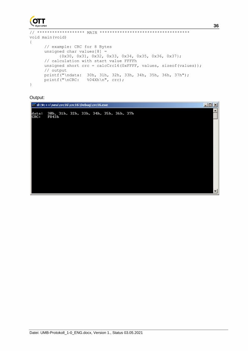
// ******************* MAIN ************************************
void main(void)
{
// example: CRC for 8 Bytes
unsigned char values[8] =
{0x30, 0x31, 0x32, 0x33, 0x34, 0x35, 0x36, 0x37};
// calculation with start value FFFFh
unsigned short crc = calcCrc16(0xFFFF, values, sizeof(values));
// output
printf("\ndata: 30h, 31h, 32h, 33h, 34h, 35h, 36h, 37h");
printf("\nCRC: %04Xh\n", crc);
}
Output:

37
Datei: UMB-Protokoll_1-0_ENG.docx, Version 1., Status 03.05.2021
4.2 Automatic Readout of a Network This section describes a mechanism which makes it possible to analyze an existing network and thereby configure the controller software.
4.2.1 Background
As this is a half-duplex network on RS485 basis without collision recognition, the controller / device principle must be observed. To scan a network, the controller would have to scan the entire address space which, with more than 30,000 possible addresses, would take too long.
Instead of this, the system is configured in the way described below for the controller software to be able to scan the network in a short period of time.
4.2.2 Necessary ID Configuration of the Sensors
The sensors are provided with device ID’s per network and device class, beginning at 1. This also corresponds to the factory settings. Additional sensors in a device class are provided with IDs in ascending order (2, 3, 4, 5 ....).
Example:
Sensors Class ID Recommended Device ID
Road sensor 1 1 1
Road sensor 2 1 2
Rain sensor 1 2 1
Rain sensor 2 2 2
Visibility sensor 1 3 1
Visibility sensor 2 3 2
NIRS 1 5 1
Weather sensor 1 7 1
Weather sensor 2 7 2
Weather sensor 3 7 3
As the different sensors have different class IDs and the address is made up of class ID and device ID, each subscriber has its own address.
4.2.3 Scanning the Network
When scanning, the controller begins to poll the sensors in ascending order of class and device ID. For this purpose, a command is used which is understood by each sensor, e.g. status request (26h).
The device ID is increased until no further reply is received to the status request. The class ID is then incremented, beginning again with device ID 1.

38
Datei: UMB-Protokoll_1-0_ENG.docx, Version 1., Status 03.05.2021
4.3 Data Types in UMB Products per TLS2002 FG3 The transmission of TLS data is based on the DE block structure. The TLS output is limited to the TLS-compliant data standardization per FG3. The answer to a measurement value request for TLS data contains the UMB channel and the measurement value. The UMB channels receive an offset of +1000 compared with DE type FG3. For multi-channel devices the offset increases by 1000 respectively.
8-bit measurement value:
Position Designation Explanation
Byte 1 Measurement value
16-bit measurement value:
Position Designation Explanation
Byte 1 Measurement value low Byte
Byte 2 Measurement value high Byte
4.3.1 Example of a TLS Measurement Value Request
A visibility measuring device is to transmit the visibility in accordance with TLS (16-bit measurement value).
DE type 60 (SW) gives UMB channel 1060 = 0424h
Request: 23h10h[<channel>²]
23h10h[24h, 04h]
Response: 23h10h<status>[<channel>², <low byte>, <high byte>]
23h10h<status>[24h, 04h, E8h, 03h]
High Byte = 03h; Low Byte = E8h; gives 03E8h = 1000d = 1000 meters visibility
4.3.2 Supported TLS-DE Types FG3
The following examples illustrate the mapping of TLS types to UMB channels. See device manuals for the types supported by each device.
DE Type
UMB Channel
Meaning Format Range Res. Coding
49 1049 Result message
Road Surface Temperature RST
16-bit -30...+80°C 0.1°C 80.0 = 800d = 0320h 0.0 = 0d = 0000h -0.1 = -1d = FFFFh -30.0 = -300d = FED4h
52 1052 Result message
Residual Salt RS
8-bit 0%...100% 1% 0% = 0d = 00h
100% = 100d = 64h
FFh = can’t be determined
65 1065 Result message
Freezing Temperature FT
16-bit -30...0 °C 0.1°C 0.0 = 0d = 0000h
-0.1 = -1d = FFFFh
-30.0 = -300d = FED4h

39
Datei: UMB-Protokoll_1-0_ENG.docx, Version 1., Status 03.05.2021
4.3.3 Derived variables
1153 float
Precipitation intensity in inch/h
Derived from channel 1053
(TLS code DE type 53 FG3)
0…..7.874 inch/h
1253 float
Precipitation intensity in mil/h
Derived from channel 1053
(TLS code DE type 53 FG3)
0…..7 874 mil/h
4.3.4 DE Type 70 “Road Surface Condition” (RSC)
Content / Characteristics
Definition
0 Road is completely dry (< approx. 30 ml/m² = 0.03 mm), free of snow and ice
1 Road is moist or wet or covered in snow or ice. The wetness or coverage is greater than approx. 30 ml/m² = 0.03 mm. No further differentiation of the type of coverage is possible.
2 … 31 Free for extensions
32 Road is wet with liquid water or watery solution. The quantity is greater than approx. 30 ml/m² = 0.03 mm No further differentiation is possible.
33 … 63 Free for extensions
64 Road is covered with freezing water or watery solution in solid form. No further differentiation is possible.
65 Road is covered with snow or slush. Mixture of liquid and frozen water or watery solution.
66 Road is covered with ice (solid, frozen water or frozen watery solution).
67 Road is covered with frost. Ice crystals sublimated from the air without covering surface with ice. The dewpoint temperature is close to the road surface temperature and below the freezing temperature.
68 … 127 Free for extensions
128 … 254 Free for codes specific to the manufacturer or user.
255 The sensors are unable to determine the status due to the prevailing conditions.
It should be noted in relation to the road section that the measurement can only ever be at one specific location and the results must therefore be interpreted accordingly.
Wetness and coverage always relate to a smooth, even surface. The estimate concerning the hazardousness of wetness or coverage in relation to the condition of the road surface (unevenness etc.) and the specific conditions of the section of road in question must be made at the control center.
It is not necessary for the sensor technology to be able to directly detect all the conditions. Rather, it is sufficient that the influences contributing to the formation of the conditions can be measured in order that the condition in question can be assumed to be probable.
It is not necessary for all characteristics to be supported by a road measuring station.
The degree of wetness or coverage, as far as can be defined, is indicated by the “water film level” (mm or l/m²).
40
Datei: UMB-Protokoll_1-0_ENG.docx, Version 1., Status 03.05.2021
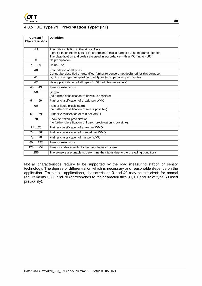
4.3.5 DE Type 71 “Precipitation Type” (PT)
Content / Characteristics
Definition
All Precipitation falling in the atmosphere. If precipitation intensity is to be determined, this is carried out at the same location. The classification and codes are used in accordance with WMO Table 4680.
0 No precipitation
1 … 39 Do not use
40 Precipitation of all types Cannot be classified or quantified further or sensors not designed for this purpose.
41 Light or average precipitation of all types (< 50 particles per minute)
42 Heavy precipitation of all types (> 50 particles per minute)
43 … 49 Free for extensions
50 Drizzle (no further classification of drizzle is possible)
51 … 59 Further classification of drizzle per WMO
60 Rain or liquid precipitation (no further classification of rain is possible)
61 … 69 Further classification of rain per WMO
70 Snow or frozen precipitation (no further classification of frozen precipitation is possible)
71 …73 Further classification of snow per WMO
74 … 76 Further classification of graupel per WMO
77 … 79 Further classification of hail per WMO
80 … 127 Free for extensions
128 … 254 Free for codes specific to the manufacturer or user.
255 The sensors are unable to determine the status due to the prevailing conditions.
Not all characteristics require to be supported by the road measuring station or sensor technology. The degree of differentiation which is necessary and reasonable depends on the application. For simple applications, characteristics 0 and 40 may be sufficient; for normal requirements 0, 60 and 70 (corresponds to the characteristics 00, 01 and 02 of type 63 used previously).

41
Datei: UMB-Protokoll_1-0_ENG.docx, Version 1., Status 03.05.2021
4.3.6 DE Type 140 “Door Contact” (DC)
As this system is limited to FG3 data but the door contact is defined in FG6 as DE type 48, DE type 140 is used as a door contact message in FG3 if this message is to be present as the only operating message.
DE Type
UMB Channel
Meaning Format Range Res. Coding
140 1140 2140
Operating message
Door Contact DC
8-bit 0 ... 1 1 00 = 0d = 00h 01 = 1d = 01h
Content Definition Switch Contact
0 Door closed open
1 Door open closed
4.3.7 DE Type 140 Inverted “Door Contact” (DC)
DE Type
UMB Channel
Meaning Format Range Res. Coding
140 1145 2145
Operating message Inverted Door Contact DC
8-bit 0 ... 1 1 00 = 0d = 00h 01 = 1d = 01h
Content Definition Switch Contact
0 Door closed closed
1 Door open open

42
Datei: UMB-Protokoll_1-0_ENG.docx, Version 1., Status 03.05.2021
4.4 Strings and Character encoding
4.4.1 Character arrays
Strings within UMB frames are not \0 terminated as they are handled as character array with fixed length. Hence all strings and char arrays should be padded with space characters.
4.4.2 ASCII-Encoding
The output of the characters for texts of all types takes place in accordance with the ASCII Code Table with the extension per ISO-8859-1 (Latin-1) or Windows-1252:
Code …0 …1 …2 …3 …4 …5 …6 …7 …8 …9 …A …B …C …D …E …F
0… NUL SOH STX ETX EOT ENQ ACK BEL BS HT LF VT FF CR SO SI
1… DLE DC1 DC2 DC3 DC4 NAK SYN ETB CAN EM SUB ESC FS GS RS US
2… SP ! " # $ % & ' ( ) * + , - . /
3… 0 1 2 3 4 5 6 7 8 9 : ; < = > ?
4… @ A B C D E F G H I J K L M N O
5… P Q R S T U V W X Y Z [ \ ] ^ _
6… ` a b c d e f g h i j k l m n o
7… p q r s t u v w x y z { | } ~ DEL
8… PAD HOP BPH NBH IND NEL SSA ESA HTS HTJ VTS PLD PLU RI SS2 SS3
9… DCS PU1 PU2 STS CCH MW SPA EPA SOS SGCI SCI CSI ST OSC PM APC
A… NBSP ¡ ¢ £ ¤ ¥ ¦ § ¨ © ª « ¬ SHY ® ¯
B… ° ± ² ³ ´ µ ¶ · ¸ ¹ º » ¼ ½ ¾ ¿
C… À Á Â Ã Ä Å Æ Ç È É Ê Ë Ì Í Î Ï
D… Ð Ñ Ò Ó Ô Õ Ö × Ø Ù Ú Û Ü Ý Þ ß
E… à á â ã ä å æ ç è é ê ë ì í î ï
F… ð ñ ò ó ô õ ö ÷ ø ù ú û ü ý þ ÿ