ultraviolet water purifiers · 2017-08-14 · the water purifier is not intended for the treatment...
TRANSCRIPT
1
Ow
ner’s Manual
Ow
ner’s ManualExtensive Product Information Available at:
ultraviolet.combuyultraviolet.com
Document No. 98-1522F1 • August 2017 • ©2017 Atlantic Ultraviolet Corporation® • ASSEMBLED IN THE USA
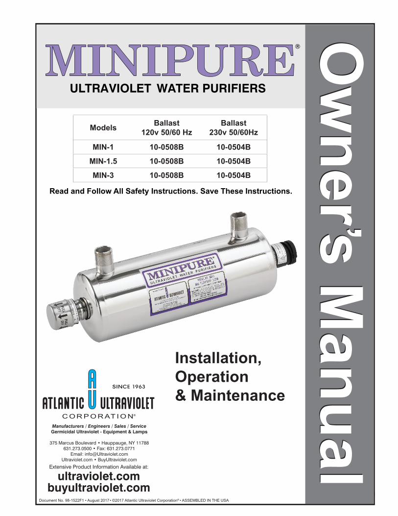
Installation, Operation & Maintenance
Read and Follow All Safety Instructions. Save These Instructions.
Models Ballast120v 50/60 Hz
Ballast230v 50/60Hz
MIN-1 10-0508B 10-0504B
MIN-1.5 10-0508B 10-0504B
MIN-3 10-0508B 10-0504B
Ow
ner ’s Manual
Ow
ner ’s Manual
ULTRAVIOLET WATER PURIFIERS
®
2
TABLE OF CONTENTSSAFETY WARNINGS .......................................................................................................................................................................3
SAFETY INSTRUCTIONS ..............................................................................................................................................................3
SAFETY LABELING ........................................................................................................................................................................3
CAUTION ...........................................................................................................................................................................................3
PRODUCT APPLICATION .............................................................................................................................................................4ConstruCtion .................................................................................................................................................................................................... 4 PrinCiPle of oPeration .................................................................................................................................................................................... 4limitation of use .............................................................................................................................................................................................. 4Water Quality ................................................................................................................................................................................................. 4
INSTALLATION ...............................................................................................................................................................................5loCation .........................................................................................................................................................................................5reCommended installation ............................................................................................................................................................5dimensional data...........................................................................................................................................................................6installation: 120v 50/60Hz (ballast no.10-0508b) ............................................................................................................... 7–8installation: 230v 50/60Hz (ballast no.10-0504b) ............................................................................................................... 7–8reCommended oPtions....................................................................................................................................................................8
MAINTENANCE ...............................................................................................................................................................................9insPeCtion .......................................................................................................................................................................................9Quartz Breakage ...........................................................................................................................................................................9lamP installation or rePlaCement: 120v 50/60Hz (ballast no.10-0508b) .............................................................................10lamP installation or rePlaCement: 230v 50/60Hz (ballast no.10-0504b) .............................................................................10Quartz sleeve installation, Cleaning or rePlaCement ............................................................................................................11rePlaCement of Broken Quartz sleeve ......................................................................................................................................12disPosal of merCury added lamP ..............................................................................................................................................12
TROUBLESHOOTING ..................................................................................................................................................................13
TECHNICAL SPECIFICATIONS .................................................................................................................................................14
WARNINGS......................................................................................................................................................................................14
REPLACEMENT PARTS ...............................................................................................................................................................15
USER ASSISTANCE .......................................................................................................................................................................16Patent notiCe ...............................................................................................................................................................................16
WARRANTY & PRODUCT REGISTRATION ...........................................................................................................................16
These instructions generally describe the installation, operation and maintenance of the MINIPURE® MIN-1, MIN-1.5 and MIN-3 Models. Questions that are not specifically answered by these instructions should be directed to the Factory.
Atlantic Ultraviolet Corporation takes all possible precautions when packaging equipment to prevent damage. Carefully inspect and report all damage upon receipt of product. Do not install damaged equipment.
Follow all instructions on all labels and tags. Carefully inspect all packing materials before discarding to prevent the loss of accessories, mounting hardware, spare parts or instructions.
The information and recommendations contained in this publication are based upon data collected by the Atlantic Ultraviolet Corporation® and are believed to be correct. However, no guarantee or warranty of any kind, expressed or implied, is made with respect to the information contained herein. Specifications and information are subject to change without notice.
3
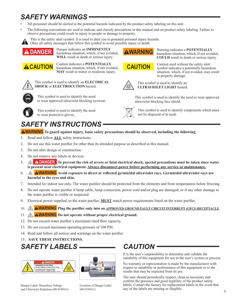
Danger Label: Hazardous Voltage and Ultraviolet Radiation (00-0199A1)
It is the user’s responsibility to determine and validate the suitability of this equipment for use in the user’s system or process.No warranty or representation is made by the manufacturer with respect to suitability or performance of this equipment or to the results that may be expected from its use.The user should periodically inspect, clean as necessary and confirm the presence and good legibility of the product safety labels. Contact the factory for replacement labels in the event that any of the labels are missing or illegible.
Location of Danger Label(00-0199A1)
SAFETY WARNINGS• All personnel should be alerted to the potential hazards indicated by the product safety labeling on this unit.• The following conventions are used to indicate and classify precautions in this manual and on product safety labeling. Failure to
observe precautions could result in injury to people or damage to property.
!This is the safety alert symbol. It is used to alert you to potential personal injury hazards. Obey all safety messages that follow this symbol to avoid possible injury or death.
SAFETY INSTRUCTIONS To guard against injury, basic safety precautions should be observed, including the following:
1. Read and follow ALL safety instructions.2. Do not use this water purifier for other than its intended purpose as described in this manual.3. Do not alter design or construction.4. Do not remove any labels or devices.5. To prevent the risk of severe or fatal electrical shock, special precautions must be taken since water
is present near electrical equipment. Always disconnect power before performing any service or maintenance.6. Avoid exposure to direct or reflected germicidal ultraviolet rays. Germicidal ultraviolet rays are
harmful to the eyes and skin.7. Intended for indoor use only. The water purifier should be protected from the elements and from temperatures below freezing.8. Do not operate water purifier if lamp cable, lamp connection, power cord and/or plug are damaged, or if any other damage to
the water purifier is visible or suspected9. Electrical power supplied, to the water purifier, MUST match power requirements listed on the water purifier.
10. Plug the purifier only into an APPROVED GROUND FAULT CIRCUIT INTERRUPT (GFCI) RECEPTACLE.
11. Do not operate without proper electrical ground.12. Do not exceed water purifier’s maximum rated flow capacity.13. Do not exceed maximum operating pressure of 100 PSI.14. Read and follow all notices and warnings on the water purifier.15. SAVE THESE INSTRUCTIONS.
SAFETY LABELS CAUTION
This symbol is used to identify the need to wear protective gloves.
Caution indicates a POTENTIALLY hazardous situation, which, if not avoided, MAY result in minor or moderate injury.
Caution used without the safety alert symbol indicates a potentially hazardous situation, which, if not avoided, may result in property damage.
This symbol is used to identify an ULTRAVIOLET LIGHT hazard.
This symbol is used to identify an ELECTRICAL SHOCK or ELECTROCUTION hazard.
Warning indicates a POTENTIALLY hazardous situation, which, if not avoided, COULD result in death or serious injury.
This symbol is used to identify the need to wear approved ultraviolet blocking eyewear.
This symbol is used to identify the need to wear approved ultraviolet blocking face shield.
This symbol is used to identify components which must not be disposed of in trash
Danger indicates an IMMINENTLY hazardous situation, which, if not avoided, WILL result in death or serious injury.
4
PRODUCT APPLICATIONConstruCtion• The water purifier is designed to mount horizontally.
• The water purifier’s chamber is passivated and electropolished type 304 Stainless Steel.
• EASY-OFF TM End Caps enable quick and easy lamp change, without disconnecting from the water supply or draining the purifier. No tools are required. Always disconnect electrical power when changing lamp.
PrinCiPle of oPerationThe MINIPURE® design has been carefully conceived to provide adequate germicidal dosage throughout the disinfection chamber. The dosage, as it applies to ultraviolet disinfection, is a function of time and the intensity of ultraviolet radiation to which the water is exposed. The exposure time, in seconds, is the total time it takes the water to flow through the disinfection chamber exposing it to the germicidal lamp. Exposure time is related to the flow rate; the higher the flow rate, the lower the exposure time or the lower the flow rate, the higher the exposure time. The ultraviolet intensity is the amount of energy, per unit time, emitted by the germicidal lamp. The dosage is the product of ultraviolet intensity and the exposure time. The operation of the MINIPURE® is as follows:
• Water enters the purifier and flows into the annular space between the quartz sleeve and the chamber wall.
• Suspended microorganisms are exposed to the ultraviolet rays emitted by the germicidal lamp.
• The LED indicator light, located on the ballast, provides visual indication of germicidal lamp operation.
• Water leaving the purifier is instantly ready for use, no further contact time is required.
limitation of useThe water purifier is intended for the use with visually clear water, not colored, cloudy or turbid. See “Water Quality” section below. The water purifier is NOT intended for the treatment of water that has an obvious contamination or intentional source, such as raw sewage, nor is the unit intended to convert wastewater to microbiologically safe drinking water.
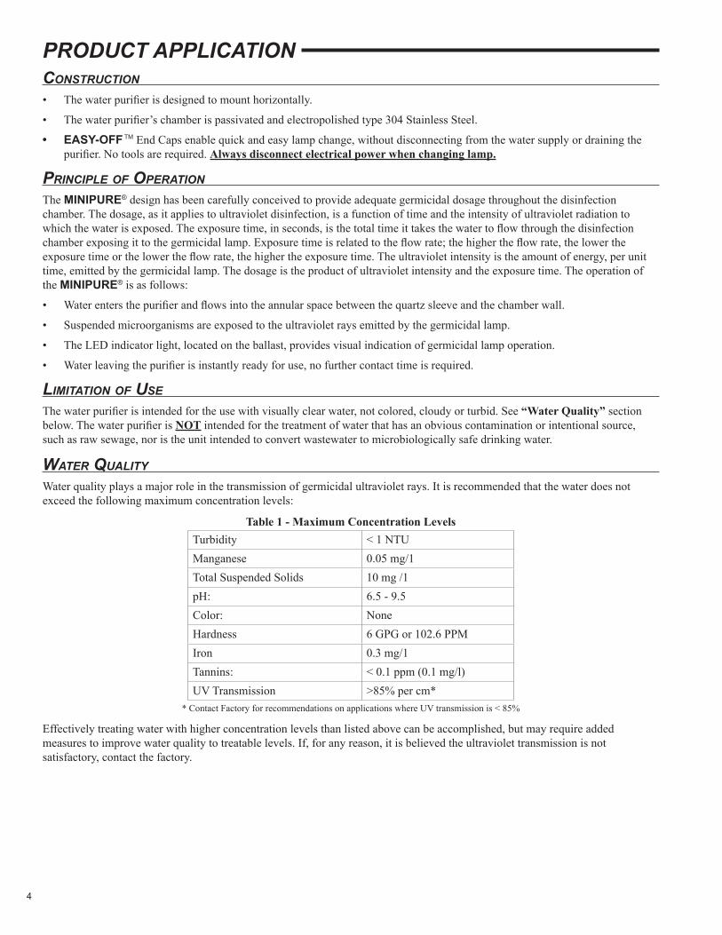
Water QualityWater quality plays a major role in the transmission of germicidal ultraviolet rays. It is recommended that the water does not exceed the following maximum concentration levels:
Table 1 - Maximum Concentration LevelsTurbidity < 1 NTUManganese 0.05 mg/1Total Suspended Solids 10 mg /1pH: 6.5 - 9.5Color: NoneHardness 6 GPG or 102.6 PPMIron 0.3 mg/1Tannins: < 0.1 ppm (0.1 mg/l)UV Transmission >85% per cm*
* Contact Factory for recommendations on applications where UV transmission is < 85%
Effectively treating water with higher concentration levels than listed above can be accomplished, but may require added measures to improve water quality to treatable levels. If, for any reason, it is believed the ultraviolet transmission is not satisfactory, contact the factory.
5
INSTALLATIONloCation1. The water purifier is intended for indoor use only. The water purifier is designed to mount horizontally. The water purifier
should be protected from the elements and from temperatures below freezing. The ambient temperature, in the area surrounding the water purifier, should be between 35o F and 100o F.
2. Electrical power supplied to the water purifier MUST match power requirements listed on the water purifier. Use of a voltage surge protector is recommended.
3. Install water purifier within 48” of a known good ground. Water Purifier will need to be installed into approved ground fault circuit interrupt (GFCI) receptacle. Where a 2-prong or unprotected 3-prong receptacle is encountered, it must be replaced by a properly grounded Ground Fault Circuit Interrupt (GFCI) receptacle. Installation must be in accordance with the National Electrical Code and any local codes and ordinances by a qualified electrician.
4. The water purifier should be located in a dry, well-lit area, which provides enough room to perform routine maintenance. This includes a minimum distance of one chamber length from the chamber end, to allow for cleaning and/or the changing of the lamp and quartz sleeve as well as a minimum of 6” on the opposite end of the water purifier. Minimum clearance to floor 18’’.
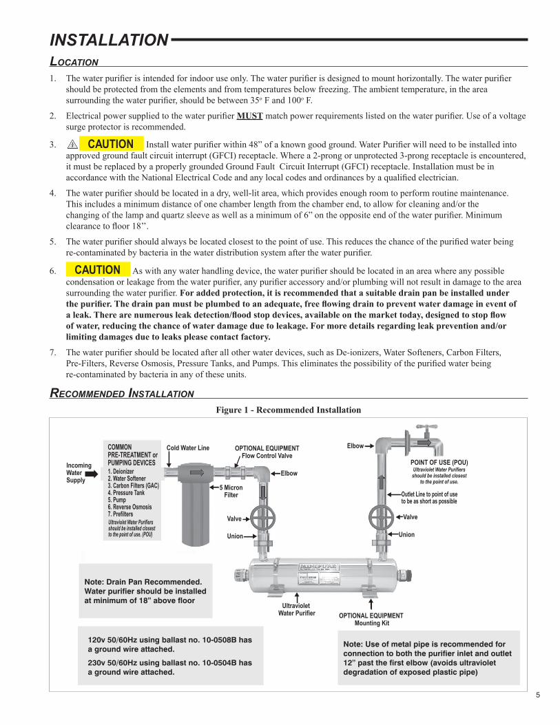
5. The water purifier should always be located closest to the point of use. This reduces the chance of the purified water being re-contaminated by bacteria in the water distribution system after the water purifier.
6. As with any water handling device, the water purifier should be located in an area where any possible condensation or leakage from the water purifier, any purifier accessory and/or plumbing will not result in damage to the area surrounding the water purifier. For added protection, it is recommended that a suitable drain pan be installed under the purifier. The drain pan must be plumbed to an adequate, free flowing drain to prevent water damage in event of a leak. There are numerous leak detection/flood stop devices, available on the market today, designed to stop flow of water, reducing the chance of water damage due to leakage. For more details regarding leak prevention and/or limiting damages due to leaks please contact factory.
7. The water purifier should be located after all other water devices, such as De-ionizers, Water Softeners, Carbon Filters, Pre-Filters, Reverse Osmosis, Pressure Tanks, and Pumps. This eliminates the possibility of the purified water being re-contaminated by bacteria in any of these units.
reCommended installationFigure 1 - Recommended Installation
�IncomingWaterSupply
COMMONPRE-TREATMENT orPUMPING DEVICES1. Deionizer2. Water Softener3. Carbon Filters (GAC)4. Pressure Tank5. Pump6. Reverse Osmosis7. Prefilters
Cold Water Line
Ultraviolet Water Purifiers should be installed closest to the point of use. (POU)
5 Micron Filter
Valve
Union
Elbow
ElbowOPTIONAL EQUIPMENTFlow Control Valve
POINT OF USE (POU)Ultraviolet Water Purifiers should be installed closest
to the point of use.
Ultraviolet Water Purifier
Outlet Line to point of use to be as short as possible
Recommended MinimumClearance for Lamp or Quartz Sleeve Removal
�
�
�
�
Union
�
�
�
�
�
�
�
�
Valve
OPTIONAL EQUIPMENT Mounting Kit
��
Model DIM. "X" MIN 1 10 3/8" MIN 1.5 14 15/16" MIN 3 12 7/8" MIN 6 22" MIN 9 29"
Use of Metal Pipe isrecommended for 12"past elbow to the inlet
or from the outlet.(avoids ultraviolet degradation
of exposed plastic pipe)
22"
120v 50/60Hz using ballast no. 10-0508B has a ground wire attached.
230v 50/60Hz using ballast no. 10-0504B has a ground wire attached.
Note: Drain Pan Recommended. Water purifier should be installed at minimum of 18” above floor
Note: Use of metal pipe is recommended for connection to both the purifier inlet and outlet 12” past the first elbow (avoids ultraviolet degradation of exposed plastic pipe)
6
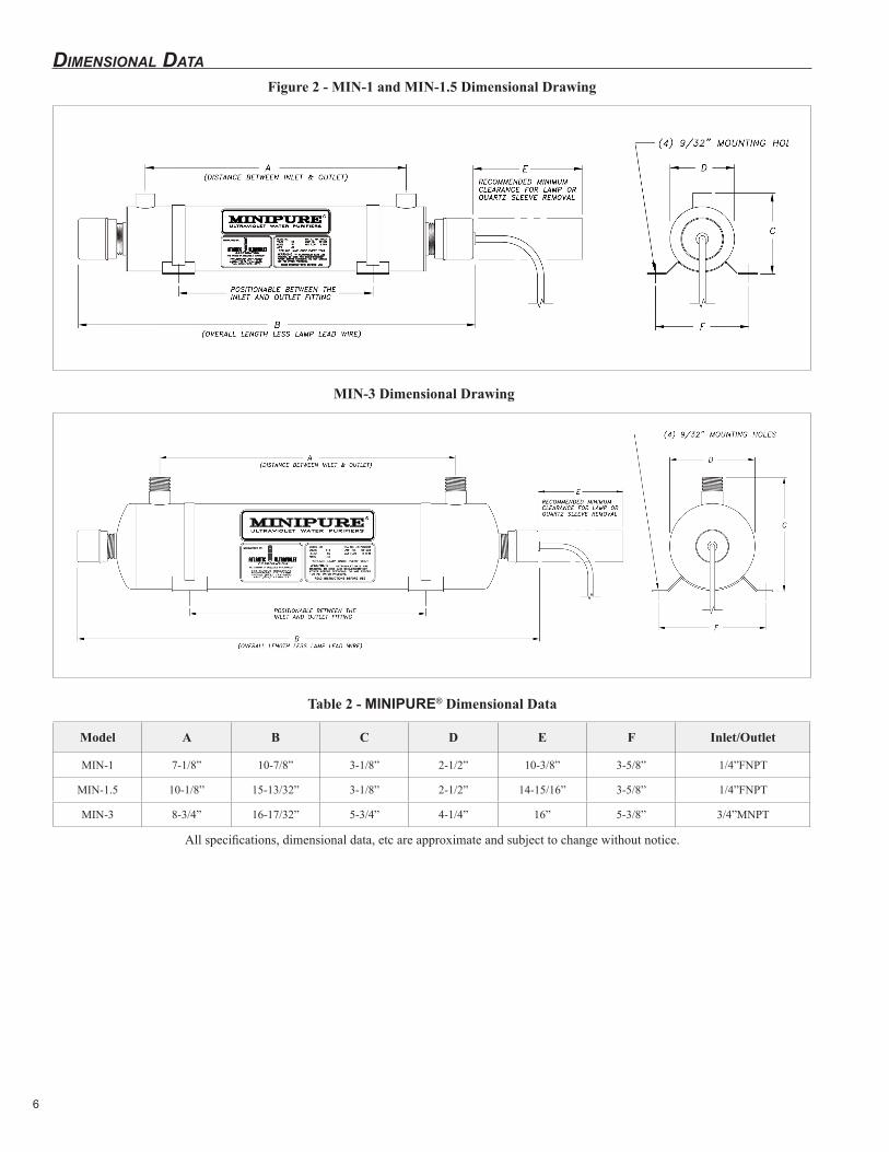
dimensional dataFigure 2 - MIN-1 and MIN-1.5 Dimensional Drawing
Table 2 - MINIPURE® Dimensional Data
Model A B C D E F Inlet/Outlet
MIN-1 7-1/8” 10-7/8” 3-1/8” 2-1/2” 10-3/8” 3-5/8” 1/4”FNPT
MIN-1.5 10-1/8” 15-13/32” 3-1/8” 2-1/2” 14-15/16” 3-5/8” 1/4”FNPT
MIN-3 8-3/4” 16-17/32” 5-3/4” 4-1/4” 16” 5-3/8” 3/4”MNPT
All specifications, dimensional data, etc are approximate and subject to change without notice.
MIN-3 Dimensional Drawing
7
installation: min-1, min-1.5, and min-3 120v 50/60Hz using ballast no.10-0508b / 230v 50/60Hz using ballast no.10-0504b
IN ORDER TO PERFORM THIS TASK, BE SURE TO WEAR THE FOLLOWING SAFETY EQUIPMENT: SAFETY GOGGLES OR A FACE SHIELD, AS WELL AS GLOVES.
1. Remove water purifier from shipping carton. Inspect water purifier, power cord and plug for damage. Do not operate if there is any damage to the purifier, power cord or plug. All models, of the MINIPURE® line of water purifiers, are shipped with the lamps packed separately. Keep the lamp aside for installation once the purifier has been properly installed.
2. Units occasionally experience damage in shipment due to the fragility of the quartz sleeve. It is therefore recommended to inspect the water purifier for damage to the quartz sleeve after it has been removed from the shipping carton. Each end of the unit as well as the inlet and outlet should be viewed to see if the quartz sleeve has experienced damage. If the quartz sleeve shows signs of damage it should be replaced before the purifier is pressurized. See “Quartz Sleeve Installation, Cleaning or Replacement” in the “Maintenance” section for the proper method of replacing the quartz sleeve in your water purifier.
3. The water purifier should be mounted horizontally on a flat dry surface. The purifier should not be solely supported by its plumbing connections. Securing the water purifier using the optional wall bracket kit is recommended.
4. The water purifier must be connected to the cold water line only. Inlet water temperature should not exceed 100o F.
5. Installation requires a 5-micron sediment filter be installed, in line, prior to the water purifier. The sediment filter will stop or trap large particulates from entering the water purifier. Particulates may cause deposits on the quartz sleeve, as well as interfere with the purifier’s ability to disinfect the water. The sediment filter may also help to reduce the amount of routine cleanings of the quartz sleeve.
6. Shut off valves should be installed on both the inlet and outlet sides of the water purifier. The use of bypass valves is not recommended. The shut off valves allow the purifier to be isolated from the water supply, which is required when removing the quartz sleeve.
7. Unions should be installed on both the inlet and outlet of the water purifier; this will allow easy removal of the water purifier from the plumbing, if required. Apply Teflon® tape to threads of inlet and outlet ports to ensure a tight seal.
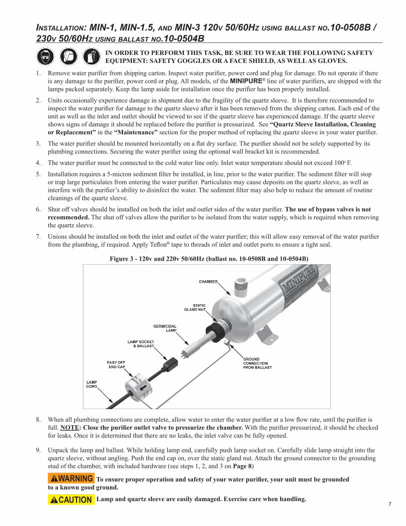
Figure 3 - 120v and 220v 50/60Hz (ballast no. 10-0508B and 10-0504B)
8. When all plumbing connections are complete, allow water to enter the water purifier at a low flow rate, until the purifier is full. NOTE: Close the purifier outlet valve to pressurize the chamber. With the purifier pressurized, it should be checked for leaks. Once it is determined that there are no leaks, the inlet valve can be fully opened.
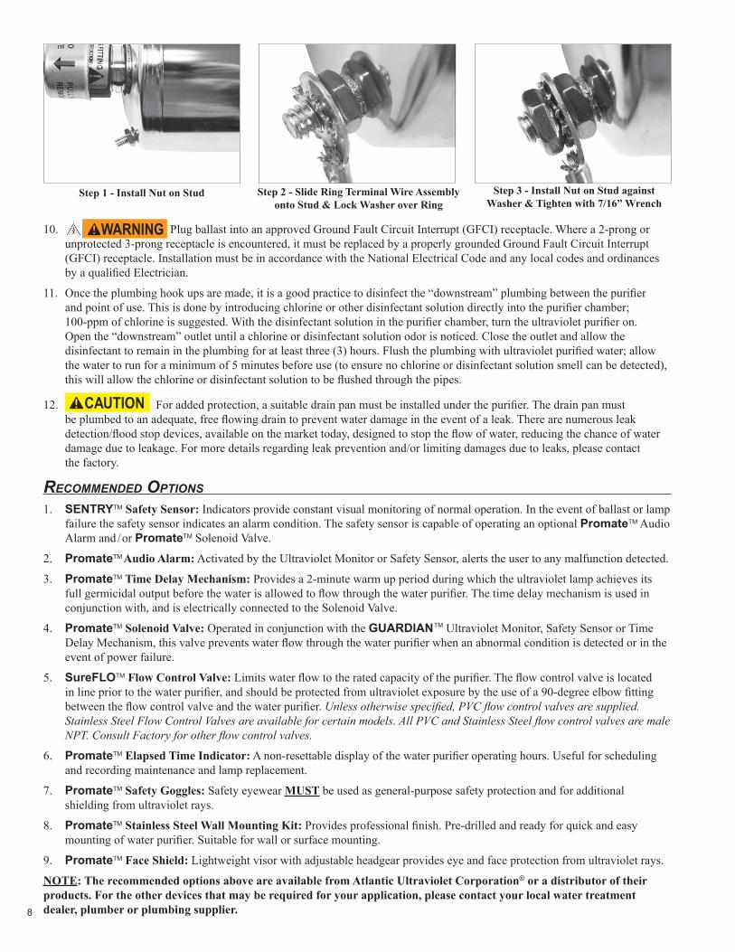
9. Unpack the lamp and ballast. While holding lamp end, carefully push lamp socket on. Carefully slide lamp straight into the quartz sleeve, without angling. Push the end cap on, over the static gland nut. Attach the ground connector to the grounding stud of the chamber, with included hardware (see steps 1, 2, and 3 on Page 8)
To ensure proper operation and safety of your water purifier, your unit must be grounded to a known good ground.
Lamp and quartz sleeve are easily damaged. Exercise care when handling.
8
10. Plug ballast into an approved Ground Fault Circuit Interrupt (GFCI) receptacle. Where a 2-prong or unprotected 3-prong receptacle is encountered, it must be replaced by a properly grounded Ground Fault Circuit Interrupt (GFCI) receptacle. Installation must be in accordance with the National Electrical Code and any local codes and ordinances by a qualified Electrician.
11. Once the plumbing hook ups are made, it is a good practice to disinfect the “downstream” plumbing between the purifier and point of use. This is done by introducing chlorine or other disinfectant solution directly into the purifier chamber; 100-ppm of chlorine is suggested. With the disinfectant solution in the purifier chamber, turn the ultraviolet purifier on. Open the “downstream” outlet until a chlorine or disinfectant solution odor is noticed. Close the outlet and allow the disinfectant to remain in the plumbing for at least three (3) hours. Flush the plumbing with ultraviolet purified water; allow the water to run for a minimum of 5 minutes before use (to ensure no chlorine or disinfectant solution smell can be detected), this will allow the chlorine or disinfectant solution to be flushed through the pipes.
12. For added protection, a suitable drain pan must be installed under the purifier. The drain pan must be plumbed to an adequate, free flowing drain to prevent water damage in the event of a leak. There are numerous leak detection/flood stop devices, available on the market today, designed to stop the flow of water, reducing the chance of water damage due to leakage. For more details regarding leak prevention and/or limiting damages due to leaks, please contact the factory.
reCommended oPtions1. SENTRYTM Safety Sensor: Indicators provide constant visual monitoring of normal operation. In the event of ballast or lamp
failure the safety sensor indicates an alarm condition. The safety sensor is capable of operating an optional PromateTM Audio Alarm and /or PromateTM Solenoid Valve.
2. PromateTM Audio Alarm: Activated by the Ultraviolet Monitor or Safety Sensor, alerts the user to any malfunction detected.
3. PromateTM Time Delay Mechanism: Provides a 2-minute warm up period during which the ultraviolet lamp achieves its full germicidal output before the water is allowed to flow through the water purifier. The time delay mechanism is used in conjunction with, and is electrically connected to the Solenoid Valve.
4. PromateTM Solenoid Valve: Operated in conjunction with the GUARDIANTM Ultraviolet Monitor, Safety Sensor or Time Delay Mechanism, this valve prevents water flow through the water purifier when an abnormal condition is detected or in the event of power failure.
5. SureFLOTM Flow Control Valve: Limits water flow to the rated capacity of the purifier. The flow control valve is located in line prior to the water purifier, and should be protected from ultraviolet exposure by the use of a 90-degree elbow fitting between the flow control valve and the water purifier. Unless otherwise specified, PVC flow control valves are supplied. Stainless Steel Flow Control Valves are available for certain models. All PVC and Stainless Steel flow control valves are male NPT. Consult Factory for other flow control valves.
6. PromateTM Elapsed Time Indicator: A non-resettable display of the water purifier operating hours. Useful for scheduling and recording maintenance and lamp replacement.
7. PromateTM Safety Goggles: Safety eyewear MUST be used as general-purpose safety protection and for additional shielding from ultraviolet rays.
8. PromateTM Stainless Steel Wall Mounting Kit: Provides professional finish. Pre-drilled and ready for quick and easy mounting of water purifier. Suitable for wall or surface mounting.
9. PromateTM Face Shield: Lightweight visor with adjustable headgear provides eye and face protection from ultraviolet rays.
NOTE: The recommended options above are available from Atlantic Ultraviolet Corporation® or a distributor of their products. For the other devices that may be required for your application, please contact your local water treatment dealer, plumber or plumbing supplier.
Step 3 - Install Nut on Stud against Washer & Tighten with 7/16” Wrench
Step 2 - Slide Ring Terminal Wire Assembly onto Stud & Lock Washer over Ring
Step 1 - Install Nut on Stud
9
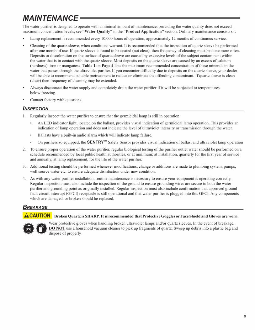
MAINTENANCEThe water purifier is designed to operate with a minimal amount of maintenance, providing the water quality does not exceed maximum concentration levels, see “Water Quality” in the “Product Application” section. Ordinary maintenance consists of:
• Lamp replacement is recommended every 10,000 hours of operation, approximately 12 months of continuous service.
• Cleaning of the quartz sleeve, when conditions warrant. It is recommended that the inspection of quartz sleeve be performed after one month of use. If quartz sleeve is found to be coated (not clear), then frequency of cleaning must be done more often. Deposits or discoloration on the surface of quartz sleeve are caused by excessive levels of the subject contaminant within the water that is in contact with the quartz sleeve. Most deposits on the quartz sleeve are caused by an excess of calcium (hardness), iron or manganese. Table 1 on Page 4 lists the maximum recommended concentration of these minerals in the water that passes through the ultraviolet purifier. If you encounter difficulty due to deposits on the quartz sleeve, your dealer will be able to recommend suitable pretreatment to reduce or eliminate the offending contaminant. If quartz sleeve is clean (clear) then frequency of cleaning may be extended.
• Always disconnect the water supply and completely drain the water purifier if it will be subjected to temperatures below freezing.
• Contact factory with questions.
insPeCtion1. Regularly inspect the water purifier to ensure that the germicidal lamp is still in operation.
• An LED indicator light, located on the ballast, provides visual indication of germicidal lamp operation. This provides an indication of lamp operation and does not indicate the level of ultraviolet intensity or transmission through the water.
• Ballasts have a built-in audio alarm which will indicate lamp failure.
• On purifiers so equipped, the SENTRYTM Safety Sensor provides visual indication of ballast and ultraviolet lamp operation
2. To ensure proper operation of the water purifier, regular biological testing of the purifier outlet water should be performed on a schedule recommended by local public health authorities, or at minimum; at installation, quarterly for the first year of service and annually, at lamp replacement, for the life of the water purifier.
3. Additional testing should be performed whenever modifications, change or additions are made to plumbing system, pumps, well source water etc. to ensure adequate disinfection under new condition.
4. As with any water purifier installation, routine maintenance is necessary to ensure your equipment is operating correctly. Regular inspection must also include the inspection of the ground to ensure grounding wires are secure to both the water purifier and grounding point as originally installed. Regular inspection must also include confirmation that approved ground fault circuit interrupt (GFCI) receptacle is still operational and that water purifier is plugged into this GFCI. Any components which are damaged, or broken should be replaced.
breakage
Broken Quartz is SHARP. It is recommended that Protective Goggles or Face Shield and Gloves are worn.
Wear protective gloves when handling broken ultraviolet lamps and/or quartz sleeves. In the event of breakage, DO NOT use a household vacuum cleaner to pick up fragments of quartz. Sweep up debris into a plastic bag and dispose of properly.
10
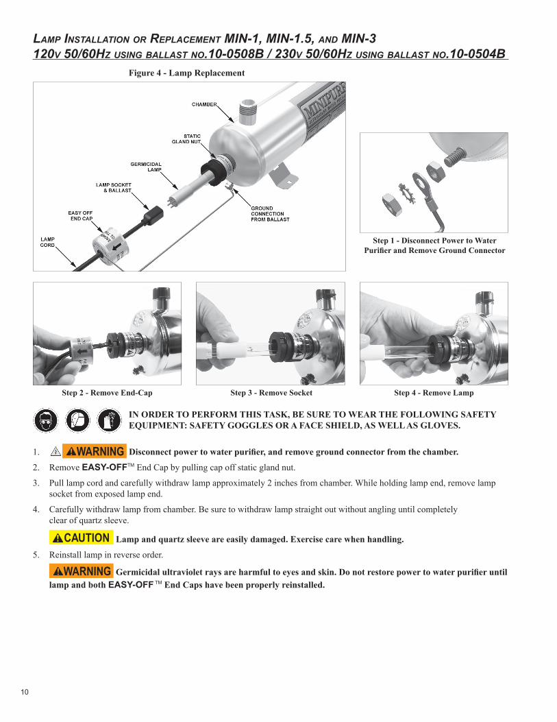
lamP installation or rePlaCement min-1, min-1.5, and min-3 120v 50/60Hz using ballast no.10-0508b / 230v 50/60Hz using ballast no.10-0504b
IN ORDER TO PERFORM THIS TASK, BE SURE TO WEAR THE FOLLOWING SAFETY EQUIPMENT: SAFETY GOGGLES OR A FACE SHIELD, AS WELL AS GLOVES.
1. Disconnect power to water purifier, and remove ground connector from the chamber.
2. Remove EASY-OFFTM End Cap by pulling cap off static gland nut.
3. Pull lamp cord and carefully withdraw lamp approximately 2 inches from chamber. While holding lamp end, remove lamp socket from exposed lamp end.
4. Carefully withdraw lamp from chamber. Be sure to withdraw lamp straight out without angling until completely clear of quartz sleeve.
Lamp and quartz sleeve are easily damaged. Exercise care when handling.
5. Reinstall lamp in reverse order.
Germicidal ultraviolet rays are harmful to eyes and skin. Do not restore power to water purifier until lamp and both EASY-OFF TM End Caps have been properly reinstalled.
Step 1 - Disconnect Power to Water Purifier and Remove Ground Connector
Step 4 - Remove LampStep 3 - Remove SocketStep 2 - Remove End-Cap
Figure 4 - Lamp Replacement
11
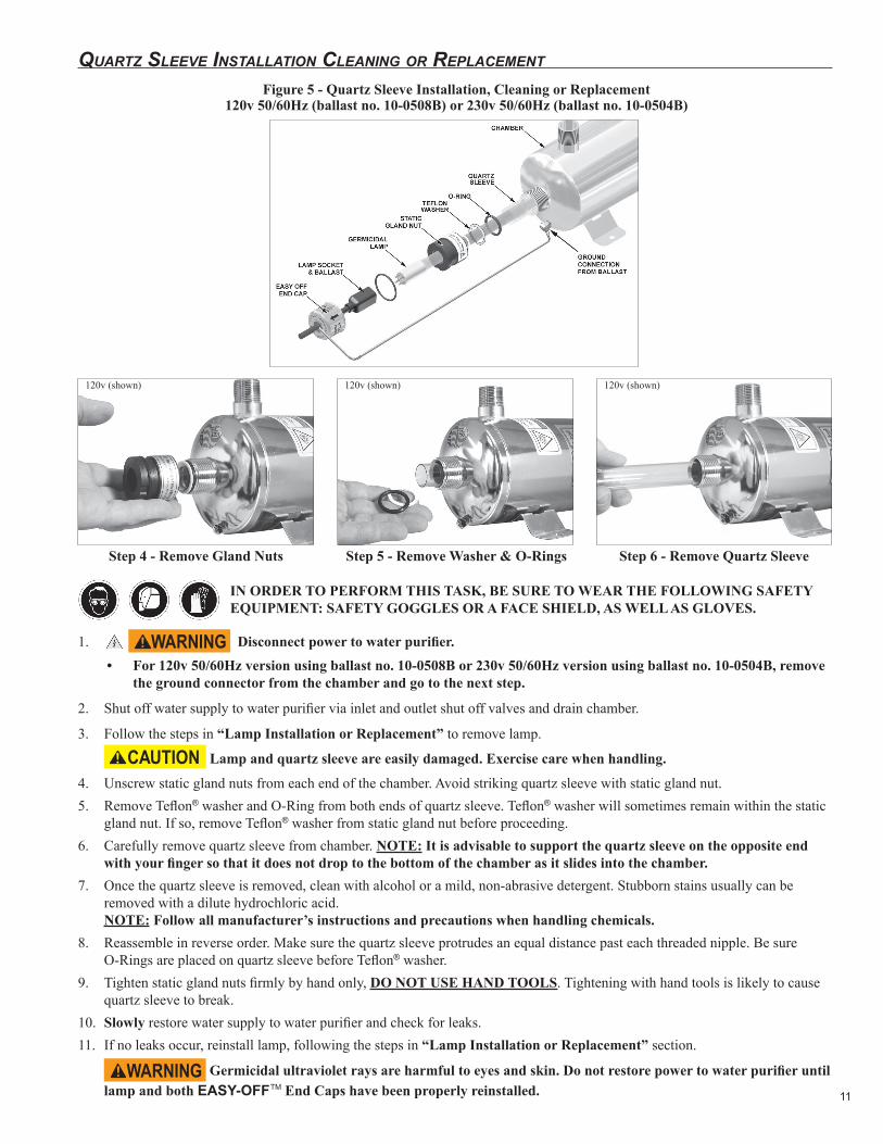
Quartz sleeve installation Cleaning or rePlaCement
Step 6 - Remove Quartz SleeveStep 5 - Remove Washer & O-RingsStep 4 - Remove Gland Nuts
Figure 5 - Quartz Sleeve Installation, Cleaning or Replacement 120v 50/60Hz (ballast no. 10-0508B) or 230v 50/60Hz (ballast no. 10-0504B)
IN ORDER TO PERFORM THIS TASK, BE SURE TO WEAR THE FOLLOWING SAFETY EQUIPMENT: SAFETY GOGGLES OR A FACE SHIELD, AS WELL AS GLOVES.
1. Disconnect power to water purifier.• For 120v 50/60Hz version using ballast no. 10-0508B or 230v 50/60Hz version using ballast no. 10-0504B, remove
the ground connector from the chamber and go to the next step.
2. Shut off water supply to water purifier via inlet and outlet shut off valves and drain chamber.
3. Follow the steps in “Lamp Installation or Replacement” to remove lamp.
Lamp and quartz sleeve are easily damaged. Exercise care when handling.
4. Unscrew static gland nuts from each end of the chamber. Avoid striking quartz sleeve with static gland nut.5. Remove Teflon® washer and O-Ring from both ends of quartz sleeve. Teflon® washer will sometimes remain within the static
gland nut. If so, remove Teflon® washer from static gland nut before proceeding.6. Carefully remove quartz sleeve from chamber. NOTE: It is advisable to support the quartz sleeve on the opposite end
with your finger so that it does not drop to the bottom of the chamber as it slides into the chamber.7. Once the quartz sleeve is removed, clean with alcohol or a mild, non-abrasive detergent. Stubborn stains usually can be
removed with a dilute hydrochloric acid. NOTE: Follow all manufacturer’s instructions and precautions when handling chemicals.
8. Reassemble in reverse order. Make sure the quartz sleeve protrudes an equal distance past each threaded nipple. Be sure O-Rings are placed on quartz sleeve before Teflon® washer.
9. Tighten static gland nuts firmly by hand only, DO NOT USE HAND TOOLS. Tightening with hand tools is likely to cause quartz sleeve to break.
10. Slowly restore water supply to water purifier and check for leaks.11. If no leaks occur, reinstall lamp, following the steps in “Lamp Installation or Replacement” section.
Germicidal ultraviolet rays are harmful to eyes and skin. Do not restore power to water purifier until lamp and both EASY-OFFTM End Caps have been properly reinstalled.
120v (shown) 120v (shown) 120v (shown)
12
rePlaCement of broken Quartz sleeve
IN ORDER TO PERFORM THIS TASK, BE SURE TO WEAR THE FOLLOWING SAFETY EQUIPMENT: SAFETY GOGGLES OR A FACE SHIELD, AS WELL AS GLOVES.
Broken Quartz is SHARP. It is recommended that protective goggles and gloves are worn when handling.
1. Disconnect power to water purifier.• For 120v 50/60Hz version using ballast no. 10-0508B or 230v 50/60Hz version using ballast no. 10-0504B, remove
the ground connector from the chamber and go to the next step.
2. Shut off water supply to water purifier via inlet and outlet shut off valves and drain chamber, if possible.
3. Follow the steps in “Quartz Sleeve Installation, Cleaning or Replacement” to remove lamp and quartz sleeve.
4. Unscrew static gland nuts from each end of the chamber. Avoid striking quartz sleeve with static gland nut.
5. Remove Teflon® washer and O-Ring from both ends of quartz sleeve. Teflon® washer will some times remain within the static gland nut. If so, remove Teflon® washer from static gland nut before proceeding.
6. Carefully remove as much of the broken quartz sleeve as possible, from each end of the chamber.
7. To remove fragments of quartz sleeve, hold the purifier vertically and shake. The quartz fragments will break and drop out of the purifier through the gland fitting. Flush water through chamber being careful to remove all quartz fragments from the interior of the chamber.
8. Carefully discard all pieces of the broken quartz sleeve.
9. Align the end of the quartz sleeve with the gland fitting of the chamber.
10. Carefully slide the quartz sleeve into the chamber, guiding it through the gland fitting. NOTE: Use care to keep the quartz sleeve parallel to the chamber, angling the quartz sleeve in any direction could result in the breakage of the quartz sleeve.
11. As the quartz sleeve nears the far end of the chamber, support the quartz sleeve by inserting your finger through the far end gland fitting and into the quartz sleeve. This will minimize the possibility of breaking the quartz sleeve as it passes through the gland fitting.
12. Center the quartz sleeve in the chamber, making sure the quartz sleeve protrudes an equal distance past each threaded gland fitting, of the chamber.
13. Re-install O-Rings, Teflon® washers, and static gland nuts. Be sure O-Rings are placed on quartz sleeve before Teflon® washer. Tighten static gland nuts firmly by hand only, DO NOT USE HAND TOOLS. Tightening with hand tools is likely to cause quartz sleeve to break.
14. When all connections are complete allow water to enter the water purifier at a low flow rate until the purifier is pressurized. With the purifier pressurized, it should be checked for leaks.
15. If no leaks occur, reinstall lamp, following the steps in “Lamp Installation or Replacement” section on Page 10.
disPosal of merCury added lamPsGermicidal ultraviolet lamps, like standard fluorescent lamps contain small amounts of mercury. Mercury added lamps should not be placed in the trash. Dispose of properly. For further information regarding the disposal and recycling of lamps containing mercury, along with Federal and State requirements visit www.lamprecycle.org. For more information on STER-L-RAY ® Germicidal Ultraviolet Lamps, visit Ultraviolet.com or BuyUltraviolet.com.
13
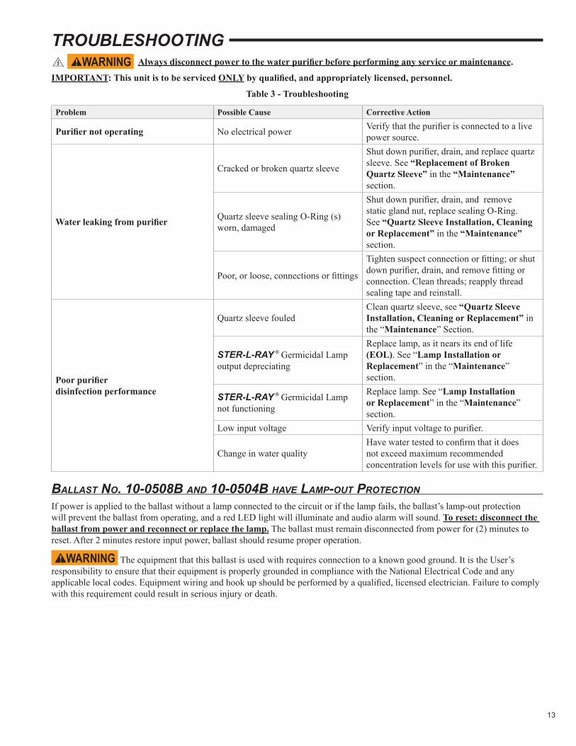
TROUBLESHOOTING Always disconnect power to the water purifier before performing any service or maintenance.
IMPORTANT: This unit is to be serviced ONLY by qualified, and appropriately licensed, personnel.
Table 3 - Troubleshooting
Problem Possible Cause Corrective Action
Purifier not operating No electrical power Verify that the purifier is connected to a live power source.
Water leaking from purifier
Cracked or broken quartz sleeve
Shut down purifier, drain, and replace quartz sleeve. See “Replacement of Broken Quartz Sleeve” in the “Maintenance” section.
Quartz sleeve sealing O-Ring (s) worn, damaged
Shut down purifier, drain, and remove static gland nut, replace sealing O-Ring. See “Quartz Sleeve Installation, Cleaning or Replacement” in the “Maintenance” section.
Poor, or loose, connections or fittings
Tighten suspect connection or fitting; or shut down purifier, drain, and remove fitting or connection. Clean threads; reapply thread sealing tape and reinstall.
Poor purifier disinfection performance
Quartz sleeve fouledClean quartz sleeve, see “Quartz Sleeve Installation, Cleaning or Replacement” in the “Maintenance” Section.
STER-L-RAY ® Germicidal Lamp output depreciating
Replace lamp, as it nears its end of life (EOL). See “Lamp Installation or Replacement” in the “Maintenance” section.
STER-L-RAY ® Germicidal Lamp not functioning
Replace lamp. See “Lamp Installation or Replacement” in the “Maintenance” section.
Low input voltage Verify input voltage to purifier.
Change in water qualityHave water tested to confirm that it does not exceed maximum recommended concentration levels for use with this purifier.
ballast no. 10-0508b and 10-0504b Have lamP-out ProteCtionIf power is applied to the ballast without a lamp connected to the circuit or if the lamp fails, the ballast’s lamp-out protection will prevent the ballast from operating, and a red LED light will illuminate and audio alarm will sound. To reset: disconnect the ballast from power and reconnect or replace the lamp. The ballast must remain disconnected from power for (2) minutes to reset. After 2 minutes restore input power, ballast should resume proper operation.
The equipment that this ballast is used with requires connection to a known good ground. It is the User’s responsibility to ensure that their equipment is properly grounded in compliance with the National Electrical Code and any applicable local codes. Equipment wiring and hook up should be performed by a qualified, licensed electrician. Failure to comply with this requirement could result in serious injury or death.
14
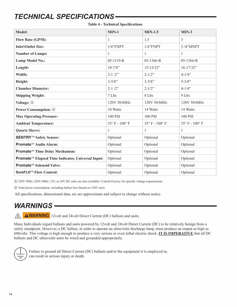
12volt and 24volt Direct Current (DC) ballasts and units.
Many Individuals regard ballasts and units powered by 12volt and 24volt Direct Current (DC) to be relatively benign from a safety standpoint. However, a DC ballast, in order to operate an ultraviolet discharge lamp, must produce an output as high as 600volts. This voltage is high enough to produce a very serious or even lethal electric shock. IT IS IMPERATIVE that all DC ballasts and DC ultraviolet units be wired and grounded appropriately.
Failure to ground all Direct Current (DC) ballasts and/or the equipment it is employed in, can result in serious injury or death.
TECHNICAL SPECIFICATIONSTable 4 - Technical Specifications
Model: MIN-1 MIN-1.5 MIN-3
Flow Rate (GPM): 1 1.5 3
Inlet\Outlet Size: 1/4”FNPT 1/4”FNPT 3 /4”MNPT
Number of Lamps: 1 1 1
Lamp Model No.: 05-1119-R 05-1366-R 05-1366-R
Length: 10-7/8” 15-13/32” 16-17/32”
Width: 2-1 /2” 2-1/2” 4-1/4”
Height: 3-5/8” 3-5/8” 5-3/8”
Chamber Diameter: 2-1 /2” 2-1/2” 4-1/4”
Shipping Weight: 7 Lbs 8 Lbs 9 Lbs
Voltage: j 120V 50/60Hz 120V 50/60Hz 120V 50/60Hz
Power Consumption: k 10 Watts 14 Watts 14 Watts
Max Operating Pressure: 100 PSI 100 PSI 100 PSI
Ambient Temperature: 35° F - 100° F 35° F - 100° F 35° F - 100° F
Quartz Sleeve: 1 1 1
SENTRYTM Safety Sensor: Optional Optional Optional
PromateTM Audio Alarm: Optional Optional Optional
PromateTM Time Delay Mechanism: Optional Optional Optional
PromateTM Elapsed Time Indicator, Universal Input: Optional Optional Optional
PromateTM Solenoid Valve: Optional Optional Optional
SureFLOTM Flow Control: Optional Optional Optional
j 220V 50Hz, 220V 60Hz, 12V, or 24V DC units are also available. Consult Factory for specific voltage requirements.
k Total power consumption, including ballast loss (based on 120V unit).
All specifications, dimensional data, etc are approximate and subject to change without notice.
WARNINGS
15
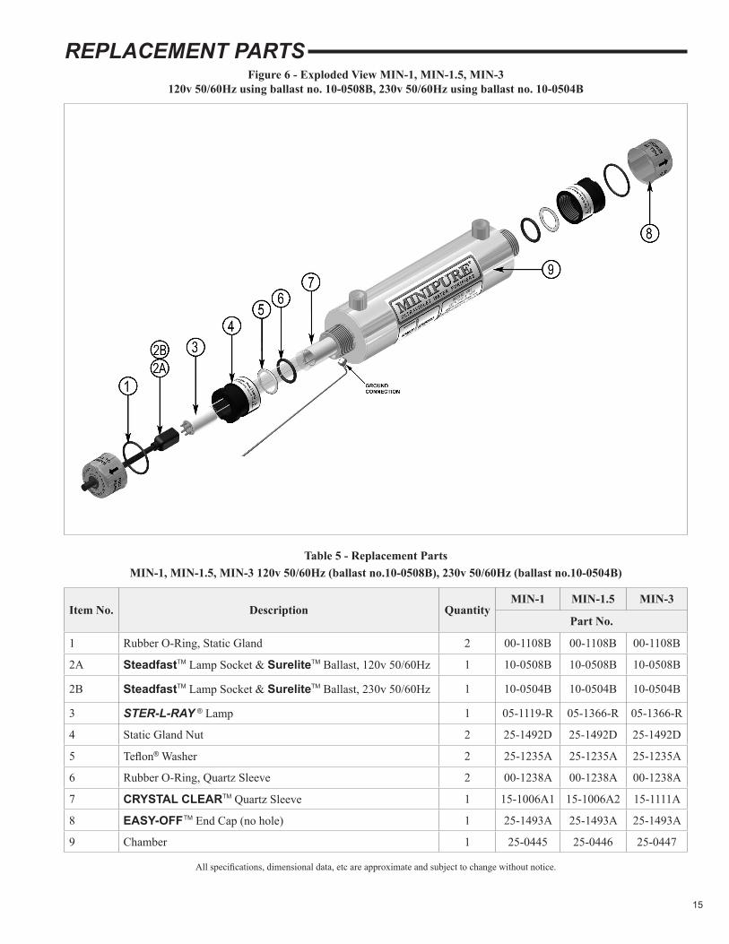
REPLACEMENT PARTSFigure 6 - Exploded View MIN-1, MIN-1.5, MIN-3
120v 50/60Hz using ballast no. 10-0508B, 230v 50/60Hz using ballast no. 10-0504B
Table 5 - Replacement Parts MIN-1, MIN-1.5, MIN-3 120v 50/60Hz (ballast no.10-0508B), 230v 50/60Hz (ballast no.10-0504B)
Item No. Description QuantityMIN-1 MIN-1.5 MIN-3
Part No.
1 Rubber O-Ring, Static Gland 2 00-1108B 00-1108B 00-1108B
2A SteadfastTM Lamp Socket & SureliteTM Ballast, 120v 50/60Hz 1 10-0508B 10-0508B 10-0508B
2B SteadfastTM Lamp Socket & SureliteTM Ballast, 230v 50/60Hz 1 10-0504B 10-0504B 10-0504B
3 STER-L-RAY ® Lamp 1 05-1119-R 05-1366-R 05-1366-R
4 Static Gland Nut 2 25-1492D 25-1492D 25-1492D
5 Teflon® Washer 2 25-1235A 25-1235A 25-1235A
6 Rubber O-Ring, Quartz Sleeve 2 00-1238A 00-1238A 00-1238A
7 CRYSTAL CLEARTM Quartz Sleeve 1 15-1006A1 15-1006A2 15-1111A
8 EASY-OFFTM End Cap (no hole) 1 25-1493A 25-1493A 25-1493A
9 Chamber 1 25-0445 25-0446 25-0447
All specifications, dimensional data, etc are approximate and subject to change without notice.
16
Patent notiCeNo attempt has been made to determine the patent status of applications illustrated or described in this publication. Inclusion in this publication of any design or method of use, which may be patented, is not to be construed as promoting or sanctioning unauthorized use.
USER ASSISTANCE
WARRANTY & PRODUCT REGISTRATION We warrant this product to the original owner to be free from defects in material and workmanship when installed in accordance with Atlantic Ultraviolet Corporation® specifications for a period of time as follows:
UV Water Purifier Chambers – Type 316 stainless steel chambers will have a Twelve (12) year Limited Warranty on the stainless steel chamber, from the date of original purchase while the Type 304 stainless steel chambers will have a Six (6) year Limited Warranty on the stainless steel chamber.
UV Air Disinfection Housing – Three (3) year Limited Warranty on the metal housing, from the date of original purchase.
Ballast – Three (3) year Limited Warranty, from the date of original purchase.
UV lamps and Other parts – One (1) year Limited Warranty from the date of original purchase.
Within the warranty period we shall repair or replace such products, which are returned to us with shipping charges prepaid and which are determined by us to be defective. This warranty will not apply to any product, which has been subjected to misuse, negligence or accident; or misapplied; or modified; or repaired by unauthorized person; or improperly installed. Warranty will be null and void if any of the product’s original labels are removed. This Limited warranty excludes the cost of labor.
The Buyer shall inspect the product promptly after receipt and shall notify us at our main office in writing of claims, including claims of breach of warranty, within thirty (30) days after the Buyer discovers or should have discovered the facts upon which the claim is based. Failure of the Buyer to give written notice of a claim within the time period shall be deemed to be a waiver of such claim.
The provisions of the above warranty are our sole obligation and exclude all other remedies or warranties, expressed or implied, including warranties of merchantability and fitness for a particular purpose, whether or not purposes or specifications are described herein. We further disclaim any responsibility whatsoever to the customer, or to any person for injury to person, damage to, or loss of property or value caused by any product which has been subjected to misuse, negligence, accident; or modified or repaired by unauthorized persons; or improperly installed.
Under no circumstances shall the Company be liable for any incidental, consequential or special damages; losses or expenses arising from the contract for this product, or in connection with the use of, or inability to use, our product for any purpose whatsoever.
Be sure to register your product and validate purchase within 30 days — registration is simple and will take less than 2 minutes to do.
NOTE – failure to register your purchase may jeopardize warranty.
Go to Ultraviolet.com and scroll down to the bottom of the page, under “Trust” click the “Warranty Registration Form”, complete and click “Submit”. Or click on “Warranty Registration PDF” to download the warranty registration card as a PDF, complete and mail to us at 375 Marcus Boulevard, Hauppauge, NY 11788, or simply fax to 631-273-0771. If you prefer to register by phone, please call 631-273-0500 and our customer service staff will be glad to assist you.
For your convenience, record the following information below. The model and serial number can be found on a label located on the MINIPURE® Ultraviolet Water Purifier. Keep this manual, along with proof of purchase, handy when contacting our offices.
Atlantic Ultraviolet Corporation® makes every effort to ensure that the MINIPURE® Ultraviolet Water Purifier is a product of superior quality and workmanship. This manual describes the installation, operation, and maintenance of the MINIPURE® Ultraviolet Water Purifier.
Please read and become familiar with the contents of this manual before installing or using this unit. If after reading the manual you still have questions, or concerns, regarding the installation or use of this unit, contact our offices, weekdays between 8:30 am and 5:00 pm Eastern Time, at:
Atlantic Ultraviolet Corporation®
375 Marcus BoulevardHauppauge, New York, 11788
Tel: 631.273.0500Fax: 631.273.0771E-mail: [email protected]: Ultraviolet.com BuyUltraviolet.com
Purchased From: Date:
Model: Serial No.: