ultrasonics - dukane · ultrasonics dukane corporation • ultrasonics division • 2900 dukane...
TRANSCRIPT

Ultrasonics
Dukane Corporation • Ultrasonics Division • 2900 Dukane Drive • St. Charles, Illinois 60174 USA • TEL (630) 797-4900 • FAX (630) 797-4949
User’s Manual
15 kHz
Assembly System
ISO 9001 Dukane products are manufacturedin ISO registered facilities
43C35043D35043E35043T350
Matching HighPower Ultra–Com
ConnectionInformation
Only
15C4001T15D4001T15E4001T15T4001T
Thruster SystemModel No.
15C4001P15D4001P15E4001P15T4001P
Press SystemModel No.
15A40004kW Generator
43A215
Column & Base
Thruster
43A216
Dukane Part No. 403–542–00.1
www.dukcorp.com
INSTALLATION and OPERATION

Copyright © 2000—2001 Dukane Corporation
All rights reserved. No part of the material protected by this copyright may be reproducedor utilized in any form or by any means, electronic or mechanical, including photocopying,recording, or by any information storage and retrieval system, without written permissionfrom Dukane Corporation.
Printed in the United States of America.
Dukane Part Number: 403–542–00
PRINTED ON RECYCLED PAPER
Dukane ultrasonic equipment is manufactured under one or more of thefollowing U.S. Patents:3,780,926 3,825,481 4,131,505 4,277,710 5,798,599 and 5,880,580

iii
Ultra 15 kHz Assembly System User’s Manual
Revision History
Revision RevisionNumber History Date
–00 Original release. 16–Mar–2001
–00.1 Online Version ONLY 23–Mar-2005Updated telephone numbers and consolidated warranty

iv
Ultra 15 kHz Assembly System User’s Manual
This page intentionally left blank.
Table of Contents
v
Table of ContentsSection 1 Introduction and Safety
Before Operating Equipment .............................................................................. 1Read this Manual First .................................................................................. 1Read the Supplementary Ultra-Com Manual.................................................. 1Watch for Special Paragraphs ...................................................................... 1
About this Manual ............................................................................................. 2Contents ....................................................................................................... 2Organization ............................................................................................... 2
System Overview ............................................................................................... 4Key Features of the Press/Thruster ..................................................................... 5Health and Safety Recommendations ................................................................. 6
Special Health Notice – Plastics .................................................................... 8Electrical Safety Grounding Instructions ........................................................ 8
120 Volt Ground Adapter ....................................................................... 930 A Generator Plug ............................................................................... 9Additional Grounding ........................................................................... 10
RFI Filter Considerations ............................................................................. 10
Section 2 InstallationBefore Unpacking ............................................................................................ 11Unpacking ....................................................................................................... 12Placement ........................................................................................................ 13
Press with Base ........................................................................................... 13Press without Base ...................................................................................... 13
Flange Template Provided ..................................................................... 13Press System Thruster Height Adjustment ..................................................... 14
Press System Basic Cable Connections ............................................................. 15Ground the System ..................................................................................... 15Cable Connections for a Press System ......................................................... 16Compressed Air ......................................................................................... 18Optional Connections ................................................................................. 19
Linear Encoder ...................................................................................... 19Top-of-Stroke Cable .............................................................................. 19
Recheck Connections .................................................................................. 19Connect Electrical Power............................................................................. 19
Installing the Thruster ....................................................................................... 20Setup Factors .............................................................................................. 20
Height Adjustment ................................................................................. 20

Ultra 15 kHz Assembly System User’s Manual
vi
Space Considerations ............................................................................ 20Mounting the Thruster ................................................................................. 21Connections for Thruster Only ..................................................................... 21Compressed Air Connection ....................................................................... 24Recheck Connections .................................................................................. 24Connect Electrical Power............................................................................. 24Flange Template ......................................................................................... 25
Section 3 Controls and IndicatorsOverview......................................................................................................... 27Front Panel ...................................................................................................... 29
Down Speed Control (DOWN SPEED) ......................................................................... 29Air Gauge (PRESSURE) .................................................................................................. 29Pressure 1 Adjustment Knob ....................................................................... 30Pressure Select Switch (WELD PRESSURE/HOLD PRESSURE) ....................................... 30Mechanical Stop Adjustment Knob.............................................................. 30Pressure 2 Adjustment Knob ....................................................................... 30Ultrasound Active Status Light (WELDER ON) ........................................................... 31Indicator Flags ........................................................................................... 31Pre-trigger Adjustment Knob ....................................................................... 32End Weld Adjustment Knob ........................................................................ 33Mechanical Stop Indicator .......................................................................... 34Trigger Control Knob .................................................................................. 34
Rear Panel ....................................................................................................... 35Press Base ....................................................................................................... 37
Base Plate .................................................................................................. 37Emergency OFF Switch ............................................................................... 37Activation Switches ..................................................................................... 38Press Status Display .................................................................................... 38
Table of ContentsSection 2 Installation, continued

Table of Contents
vii
Section 4 Press OptionsOverview......................................................................................................... 39Linear Encoder ................................................................................................ 39
Purpose ...................................................................................................... 39Components ............................................................................................... 39
Installing the Linear Encoder Kit ....................................................................... 40Remove Standard Right Side Panel ............................................................. 40Install Kit Components ................................................................................ 40Alignment .................................................................................................. 41Testing ....................................................................................................... 42Attach Side Panel ....................................................................................... 42
Electronic Pressure Regulator ........................................................................... 43Pressure Transducer ......................................................................................... 43Load Cell ......................................................................................................... 44
Section 5 Stack/Fixture SetupOverview......................................................................................................... 45Stack Description ............................................................................................. 45Changing Stack Components ........................................................................... 46
Stack Removal ............................................................................................ 47Stack Disassembly ...................................................................................... 49Stack Assembly .......................................................................................... 50
Preassembly Check ................................................................................ 50Mounting Studs ..................................................................................... 51Horn to Booster or Booster to Transducer Assembly ............................... 51
Installing the Stack...................................................................................... 53Fixture Installation ........................................................................................... 54
Fixture Alignment ....................................................................................... 54Leveling the Fixture ..................................................................................... 56
Table of Contents
Ultra 15 kHz Assembly System User’s Manual
viii
Table of Contents
Section 7 System TestOverview......................................................................................................... 67
Auto-Trac Tuning ........................................................................................ 67Operational Stack Test ..................................................................................... 68
Pre-test Checklist ........................................................................................ 68Acoustic Stack Test ..................................................................................... 69
Acceptable Results ................................................................................. 70Unacceptable Results ............................................................................. 70
Range Adjustment of the Auto-Trac Feature ................................................ 71Cycling the System........................................................................................... 74Running Sample Parts ...................................................................................... 75
Section 6 4000 Watt GeneratorOverview......................................................................................................... 57Safety Considerations ...................................................................................... 57Electrical Grounding Instructions ...................................................................... 58RFI Filter .......................................................................................................... 59Regulatory Agency Compliance ....................................................................... 59Installation ....................................................................................................... 60
Site Selection .............................................................................................. 60Connections ............................................................................................... 60
Front Panel Controls ........................................................................................ 61AC Power ON/OFF Switch ......................................................................... 61OPERATE/STOP/TEST Switch ..................................................................... 61
OPERATE Position ................................................................................. 61STOP Position ........................................................................................ 61TEST Position ......................................................................................... 61
OUTPUT POWER LEVEL .............................................................................. 62Red OVERLOAD Light ........................................................................... 62POWER Control Knob ........................................................................... 62Auto–Trac Range Control Potentiometer ................................................. 62
Rear Panel ....................................................................................................... 63Power Cord ................................................................................................ 63J1 U/S Output ............................................................................................ 63J20 OPERATIONAL Control ........................................................................ 63J23 STATUS RELAY .................................................................................... 64Ground ...................................................................................................... 64
Space Requirements......................................................................................... 64Identification Numbers ..................................................................................... 65

Table of Contents
ix
Section 9 MaintenanceOverview......................................................................................................... 81Stack Maintenance .......................................................................................... 81
Overview ................................................................................................... 81Inspecting the Stack .................................................................................... 82
Surfaces with Even Contact .................................................................... 82Surfaces with Uneven Contact ................................................................ 82Crowning .............................................................................................. 82Center Depression ................................................................................. 82Corrosion .............................................................................................. 83
Reconditioning Stack Components.................................................................... 84Overview ................................................................................................... 84Reconditioning the Mating Surfaces ............................................................ 84Machining .................................................................................................. 84Manual Resurfacing.................................................................................... 84
Torque Values ................................................................................................. 87Overview ................................................................................................... 87Stack Assembly Torque Values .................................................................... 87Booster and Horn Stud Torque Values ......................................................... 87
Press/Thruster Maintenance ............................................................................. 88Daily Inspection .......................................................................................... 88Six-Month Periodic Maintenance ................................................................ 88
Section 8 System OperationOverview......................................................................................................... 77Daily Start-up Checklist .................................................................................... 77Start-up ........................................................................................................... 78
Manual Start ......................................................................................... 78Automatic Start ..................................................................................... 78
Stopping the System ........................................................................................ 79Normal Conditions ..................................................................................... 79Emergency Conditions ................................................................................ 79
Manual System...................................................................................... 79Automated System................................................................................. 79
Making Changes to the System ........................................................................ 80
Power Draw ............................................................................................... 75If Overloading Occurs ........................................................................... 75
Assembled Part Quality .............................................................................. 75Making Adjustments ................................................................................... 75
Section 7 (continued)

Ultra 15 kHz Assembly System User’s Manual
x
Table of Contents
Section 11 Dukane Contacts and Warranty
Contacting Dukane Corporation..................................................................... 113Local Support ................................................................................................ 113
Try Our Website ....................................................................................... 113Contacts in the Ultrasonics Division ........................................................... 113Ultrasonics Division E-mail Addresses ......................................................... 114Ultrasonics Division Phone Numbers ........................................................... 114
Dukane Corporation WarrantyUSA, Canada, Mexico.............................................................................. 115International ............................................................................................. 116
Section 12 Specifications
Regulatory Agency Compliance ..................................................................... 117System Standard Components ........................................................................ 118System Requirements ..................................................................................... 119
Compressed Air ....................................................................................... 119Electrical .................................................................................................. 119Space ....................................................................................................... 119Weight ..................................................................................................... 119
Press/Thruster Dimensions ............................................................................. 120Operating Environment .................................................................................. 121Identification Numbers ................................................................................... 122
Overview......................................................................................................... 91Process Troubleshooting ............................................................................. 91Equipment Troubleshooting ......................................................................... 91
Process Troubleshooting ................................................................................... 92Primary Weld Characteristics...................................................................... 92Welding ..................................................................................................... 93Insertion ................................................................................................... 100Staking..................................................................................................... 103Continuous Welding ................................................................................. 106
Equipment Troubleshooting ............................................................................ 108
Section 10 Troubleshooting

Table of Contents
xi
List of Figures1-1 Example of 120 V, Grounded, 3-Prong Receptacle .................................... 81-2 Example of120 V Ground Adapter Hookup ............................................... 91-3 Example of 30A Plug ................................................................................. 91-4 Typical Equipment Grounding Arrangement............................................. 102-1 Unpacking............................................................................................... 122-2 Press Placement ....................................................................................... 132-3 Adjusting the Column Clamps .................................................................. 142-4 Press Right Side View .............................................................................. 142-5 Press System Cable Connections .............................................................. 162-6 Thruster Air Inlet Detail ............................................................................ 182-7 Mounting the Thruster .............................................................................. 212-8 Thruster System Cable Connections .......................................................... 222-9 Base Flange Template (full scale).............................................................. 253-1 Standard Press Controls Locations............................................................ 273-2 Front Panel 15 kHz Thruster ..................................................................... 283-3 Trigger Control Knob ............................................................................... 343-4 Rear Press Panel ...................................................................................... 353-5 Air Lockout Valve Detail .......................................................................... 363-6 Press Ergonomic Base .............................................................................. 37
4-1 Linear Encoder Components .................................................................... 394-2 Linear Encoder Mounting Detail ............................................................... 404-3 Linear Encoder Alignment ........................................................................ 415-1 Stack Components ................................................................................... 455-2 Stack Disassembly and Assembly ............................................................. 465-3 Stack Removal ......................................................................................... 475-4 Stack Disassembly ................................................................................... 495-5 Assembling Stack Components ................................................................ 505-6 Input/Output Ends Identified .................................................................... 515-7 Installing the Stack ................................................................................... 535-8 Fixture Installation ................................................................................... 545-9 Fixture Mounting Hole Measurements ...................................................... 556-1 Generator Front Panel ............................................................................. 616-2 Generator Rear Panel .............................................................................. 636-3 Generator Identification Number Locator ................................................. 657-1 Paper Test ............................................................................................... 707-2 Range Control Potentiometer Slot in Home Position .................................. 72
Table of Contents

Ultra 15 kHz Assembly System User’s Manual
xii
8-1 Press Base Switches ................................................................................. 798-2 Primary Reference Documents for Subsystems .......................................... 809-1 Location of Stack Mating Surfaces ........................................................... 819-2 Burnished Area Indicates Flat Mating Surfaces ......................................... 829-3 Burnished Area Indicates Uneven Mating Surfaces ................................... 829-4 Example of Crowning .............................................................................. 829-5 Example of Center Depression ................................................................. 829-6 Manual Resurfacing ................................................................................. 85
10-1 Ultra-Com Input for Emergency Stop Switch ........................................... 11012-1 Front View of Press ................................................................................ 12012-2 Left Side View of Press ........................................................................... 12012-3 Top View of Press Base .......................................................................... 12012-4 Location of Model and Serial Numbers .................................................. 122
Table of ContentsList of Figures, continued

Table of Contents
xiii
List of Tables2-1 Approximate Dimensions and Weights .................................................... 112-2 Press System Basic Connections ............................................................... 172-3 Thruster System Basic Cable Connections ................................................. 233-1 Thruster Symbols ..................................................................................... 296-1 Generator Connections ............................................................................ 607-1 Test Procedure Indications ....................................................................... 699-1 Booster and Horn Stud Torque ................................................................. 87
10-1 Equipment Requirements for Primary Weld Characteristics ....................... 9212-1 Ultra 15 kHz Systems Standard Components.......................................... 11812-2 Component Dimensions and Weights ..................................................... 11912-3 Miscellaneous Dimensions ..................................................................... 121
Table of Contents

Ultra 15 kHz Assembly System User’s Manual
xiv
This page intentionally left blank

Dukane Corporation
SECTION 1
Introduction and Safety
• This section introduces the User’s Manualand the equipment, and also deals withsafety considerations.

Dukane Corporation
This page intentionally left blank

Section 1 Introduction and Safety
1
Before Operating EquipmentBefore you operate the equipment, please follow the recom-mendations given here.
Read this Manual FirstBefore operating the equipment, read this User’s Manual toget familiar with the Ultra Assembly System.
Because the Ultra-Com High Power process controller is anintegral part of your plastics assembly system, please read theUser’s Manual (Dukane Part No. 403-393C) before operating thesystem. The Ultra-Com manual is a companion to this User’sManual, and it supplements information provided here.
By reading both manuals you will have gained basic under-standing of equipment operation. This will be helpful inlearning the plastics assembly system’s potential throughpractical, hands-on process work.
Watch for Special ParagraphsWatch for these special kinds of paragraphs in this manual:
NOTENote statements highlight procedures or provide information.
CAUTION Caution statements identify conditions or prac-tices that could result in damage to the equip-ment or other property.
WARNING
Warning statements point out conditions orpractices that could result in personal injuryor loss of life.
Read the Supplementary Ultra-Com Manual
Ultra 15 kHz Assembly System User’s Manual
2
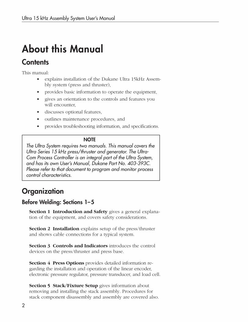
About this ManualContentsThis manual:
• explains installation of the Dukane Ultra 15kHz Assem-bly system (press and thruster),
• provides basic information to operate the equipment,
• gives an orientation to the controls and features youwill encounter,
• discusses optional features,
• outlines maintenance procedures, and
• provides troubleshooting information, and specifications.
OrganizationBefore Welding: Sections 1–5
Section 1 Introduction and Safety gives a general explana-tion of the equipment, and covers safety considerations.
Section 2 Installation explains setup of the press/thrusterand shows cable connections for a typical system.
Section 3 Controls and Indicators introduces the controldevices on the press/thruster and press base.
Section 5 Stack/Fixture Setup gives information aboutremoving and installing the stack assembly. Procedures forstack component disassembly and assembly are covered also.
The Ultra System requires two manuals. This manual covers theUltra Series 15 kHz press/thruster and generator. The Ultra-Com Process Controller is an integral part of the Ultra System,and has its own User’s Manual, Dukane Part No. 403-393C.Please refer to that document to program and monitor processcontrol characteristics.
NOTE
Section 4 Press Options provides detailed information re-garding the installation and operation of the linear encoder,electronic pressure regulator, pressure transducer, and load cell.

Section 1 Introduction and Safety
3
Organization, Before Welding, continued
The Index provides page references for key terms andconcepts used in this manual.
Section 6 4000 Watt Generator provides informationon.installation, the front panel controls, rear panel connec-tions and basic operation of the generator.
Section 7 System Test provides the testing methodsused to ensure that the press system is functioning prop-erly before normal operations start
Section 8 System Operation provides a start-up check-list, start-up and shut down procedures and things toconsider when making changes to the system.
Section 9 Maintenance provides information on main-taining the stack components and the press/thruster.
Section 10 Troubleshooting provides a list of the morecommon problems that may occur in the various ultrasonicprocesses. It also provides suggested corrective actions.
Section 11 Dukane Corporation Contacts and War-ranty gives contact information for members of theDukane Ultrasonics factory support team. The warrantyalso appears in this section.
Section 12 Specifications gives technical specs andinformation about the 4,000 watt generator and the Ad-vanced Programmer.
Basics of Operation: Sections 6–8
Supporting Information: Sections 9 –12
Ultra 15 kHz Assembly System User’s Manual
4
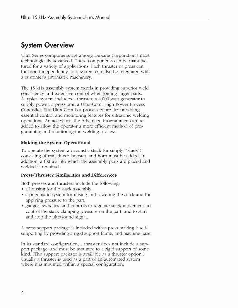
System OverviewUltra Series components are among Dukane Corporation's mosttechnologically advanced. These components can be manufac-tured for a variety of applications. Each thruster or press canfunction independently, or a system can also be integrated witha customer’s automated machinery.
The 15 kHz assembly system excels in providing superior weldconsistency and extensive control when joining larger parts.A typical system includes a thruster, a 4,000 watt generator tosupply power, a press, and a Ultra-Com High Power ProcessController. The Ultra-Com is a process controller providingessential control and monitoring features for ultrasonic weldingoperations. An accessory, the Advanced Programmer, can beadded to allow the operator a more efficient method of pro-gramming and monitoring the welding process.
Press/Thruster Similarities and Differences
Both presses and thrusters include the following:• a housing for the stack assembly,• a pneumatic system for raising and lowering the stack and for
applying pressure to the part,• gauges, switches, and controls to regulate stack movement, to
control the stack clamping pressure on the part, and to startand stop the ultrasound signal.
A press support package is included with a press making it self-supporting by providing a rigid support frame, and machine base.
In its standard configuration, a thruster does not include a sup-port package, and must be mounted to a rigid support of somekind. (The support package is available as a thruster option.)Usually a thruster is used as a part of an automated systemwhere it is mounted within a special configuration.
To operate the system an acoustic stack (or simply, “stack”)consisting of transducer, booster, and horn must be added. Inaddition, a fixture into which the assembly parts are placed andwelded is required.
Making the System Operational

Section 1 Introduction and Safety
5
• Ultra-rigid Square Support Column with rack andpinion height adjustment and up to 10° of radial align-ment capability.
• Heavy Duty Precision Slide assembly with 1" (25.4mm) diameter steel rods and sealed Thomson ball bush-ings preloaded for reliable, frictionless operation.
• Height Adjustment Handwheel is supplied, and it canbe specified for mounting on either side of the press.
• Gas Strut counterbalence for easy height adjustment.
• Stroke of 6.75" (171 mm) with mechanical bottom stopadjustable in .001" (.025 mm) increments.
• Dual Pressure allows for an increased clamp force im-proving melt during the weld cycle, or greater pressure inthe Hold portion of the cycle to strengthen the weld.
• Calibrated Dynamic Trigger system with LED indicatorstarts the ultrasonic signal at a precise, user-selectable force.
• Pre-trigger and End-of-Weld (lower) limit switches arestandard and adjustable in .001" (.025 mm) increments.
• Top-of-Stroke limit switch for automated applications.
• Ergonomic Base and cycle activation switches reduceoperator fatigue; optional opti-touch cycle activationswitches are available.
• Status Indicators in base for POWER, IN CYCLE, andABORT clearly communicate system operating status.
• Twist Release EMERGENCY OFF switch on the press basemeets international safety standards.
Key Features of the Press/Thruster
• Advanced Programmer keyboard and monitor pro-vide an option for more efficient programming.

Ultra 15 kHz Assembly System User’s Manual
6
Proper Installation - Operate system components only afterthey are properly installed.
No Unauthorized Modifications - Do not modify your systemin any way unless authorized to do so by Dukane Corporation.Unauthorized modifications could cause equipment damage and/or injury to the operator. In addition, unauthorized modificationswill void equipment warranty.
Keep the Cover On - Do not remove any equipment coverunless directed to do so by Dukane Corporation.
Grounded Electrical Power - Operate this equipment only witha grounded electrical connection. (See Electrical Safety Ground-ing Instructions on Page 8.)
Comply with Regulations - You may be required to add accesso-ries to bring the system into compliance with applicable regulations(OSHA in the USA) for machine guarding and noise exposure.
Health and Safety RecommendationsPlease observe these health and safety recommendations for safe,efficient, and injury-free operation of your equipment.
NOTE
These recommendations apply to the welding system. “System” inthis manual refers to a complete group of components associatedwith the welding of parts, also known as an ultrasonic assemblysystem. A typical Ultra System consists of the Ultra-Com ultra-sonic process controller, a generator, a press with thruster,switches, controls, cables, transducer, booster, horn, and fixture.
CAUTIONAt some time you may be asked to remove equip-ment covers by the Dukane Service Dept. person-nel. Before doing so, disconnect the unit electri-
cally from the incoming line AC power. If the unit is a press/thruster, lock the Air Lockout Valve, located on the rearpanel, in its closed position. See Figure 3-5 on Page 36.
Section 1 Introduction and Safety
7
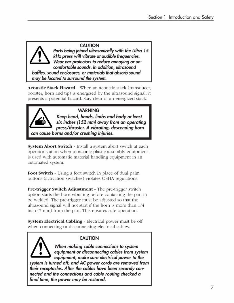
System Abort Switch - Install a system abort switch at eachoperator station when ultrasonic plastic assembly equipmentis used with automatic material handling equipment in anautomated system.
Foot Switch - Using a foot switch in place of dual palmbuttons (activation switches) violates OSHA regulations.
Pre-trigger Switch Adjustment - The pre-trigger switchoption starts the horn vibrating before contacting the part tobe welded. The pre-trigger must be adjusted so that theultrasound signal will not start if the horn is more than 1/4inch (7 mm) from the part. This ensures safe operation.
CAUTION
When making cable connections to systemequipment or disconnecting cables from systemequipment, make sure electrical power to the
system is turned off, and AC power cords are removed fromtheir receptacles. After the cables have been securely con-nected and the connections and cable routing checked afinal time, the power may be restored.
Acoustic Stack Hazard - When an acoustic stack (transducer,booster, horn and tip) is energized by the ultrasound signal, itpresents a potential hazard. Stay clear of an energized stack.
System Electrical Cabling - Electrical power must be offwhen connecting or disconnecting electrical cables.
CAUTION
WARNINGKeep head, hands, limbs and body at leastsix inches (152 mm) away from an operatingpress/thruster. A vibrating, descending horn
can cause burns and/or crushing injuries.
Parts being joined ultrasonically with the Ultra 15kHz press will vibrate at audible frequencies.Wear ear protectors to reduce annoying or un-comfortable sounds. In addition, ultrasound
baffles, sound enclosures, or materials that absorb soundmay be located to surround the system.

Ultra 15 kHz Assembly System User’s Manual
8
Special Health Notice – PlasticsBefore using any Dukane ultrasonic system, become familiarwith applicable regulations about the particular type ofplastic(s) you are using. (In the USA check with the U.S.Department of Labor.)
When plastic materials are being processed, they may emitfumes and/or gases that could be hazardous.
Make sure there is proper ventilation whenever these plasticsare processed.
Electrical Safety Grounding InstructionsFor safety, the power cords used on all Dukane products have athree-prong, grounding-type plug. The type typically used withthe Ultra-Com is shown in Figure 1-1. The plug typically usedwith the 4000 watt generator is shown in Figure 1-3.
If you must use a two-prong electrical receptacle,we strongly recommend that you replace it witha properly grounded three-prong type. Have aqualified electrician replace it following theNational Electric Code and any local codes and
ordinances that apply. See Figures 1-1 and 1-2.
If there is any question about the grounding ofyour receptacle, have it checked by a qualifiedelectrician.Do not cut off the power cord grounding prong
or alter the plug in any way.Extension Cord: If an extension cord is needed, use a three-wire cord that’s in good condition. The cord should be largeenough to do the job safely. It, too, must be plugged into agrounded receptacle. Do not use a two-wire extension cordwith this product.
CAUTION
CAUTION Approved 2 pole, 3 wire groundingreceptacle BRYANT No. 5261 or equivalentto NEMA 5-15R OR 5-20R
Figure 1-1 Example of 120 V,Grounded, 3-Prong Receptacle

Section 1 Introduction and Safety
9
120 Volt Ground Adapter
If it is impossible to change the wall receptacle to an approvedgrounding-type, and where local codes permit, you may use anadapter to connect the three-prong grounding plug to the two-prong receptacle. (See Figure 1-2.)
The green pigtail on the adapter MUST BE CONNECTED TO GROUND.
If the receptacle is grounded, the pigtail may be connected to it.
If the receptacle is not grounded, connect a separate 14 AWG(1.63mm dia.) ground wire from the receptacle to the nearesteffectively grounded metal pipe or equivalent grounding elec-trode.
1
2
4
3
5
6
7
8
9
1 - Power cord w/ 3 - prong plug2 - Adapter assembly3 - Wall Plate4 - Receptacle5 - Cold water pipe (metal)6 - Ground clamp7 - Mounting screw8 - Green ground lead9 - 14 AWG (1.63mm ø) ground wire
Figure 1-2 Example of Proper 120 V Ground Adapter Hookup
CAUTION
Figure 1-3 Example of 30A Plug
30A Generator PlugThe 15 kHz system generator power cord uses the twist-locktype of plug shown in Figure 1-3. Make sure its receptacle isgrounded properly.

Ultra 15 kHz Assembly System User’s Manual
10
Additional GroundingGrounding lugs have been provided on the Ultra-Com, gen-erator, press base, and thruster (See Figure 1-4.) to meet anyadditional grounding requirements that may arise.Use 18 AWG ground wire for the ground connection betweenthe press/thruster, the Ultra-Com and the generator.
RFI Filter ConsiderationsIn addition to the safety considerations above, proper ground-ing at the generator power cord is essential for the effectiveoperation of the RFI (Radio Frequency Interference) filter inevery Dukane generator. The filter prevents linenoise from entering the control circuitry of theultrasonic equipment, as well as blockingultrasonic RFI from the powerline.
Figure 1-4 Typical Equipment Grounding Arrangement
Generator: To 240 VAC Power
To Earth Ground,a grounded metal pipe or
a grounding electrode.
Ground Connectionon back of thruster.(Use this when thethruster is not usedwith a press supportpackage.)
Press BaseGround
Connection
Ultra-Com: To 120 VAC Power

Dukane Corporation
SECTION 2
Installation
• This section deals with basic installation,locating and cabling the equipment.

Dukane Corporation
This page intentionally left blank
Section 2 Installation
11
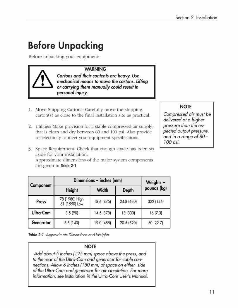
Before UnpackingBefore unpacking your equipment:
Cartons and their contents are heavy. Usemechanical means to move the cartons. Liftingor carrying them manually could result inpersonal injury.
1. Move Shipping Cartons: Carefully move the shippingcarton(s) as close to the final installation site as practical.
2. Utilities: Make provision for a stable compressed air supply,that is clean and dry between 80 and 100 psi. Also providefor electricity to meet your equipment specifications.
3. Space Requirement: Check that enough space has been setaside for your installation.Approximate dimensions of the major system componentsare given in Table 2-1.
WARNING
Table 2-1 Approximate Dimensions and Weights
NOTE
NOTE
Compressed air must bedelivered at a higherpressure than the ex-pected output pressure,and in a range of 80 -100 psi.
Add about 5 inches (125 mm) space above the press, andto the rear of the Ultra-Com and generator for cable con-nections. Allow 6 inches (150 mm) of space on either sideof the Ultra-Com and generator for air circulation. For moreinformation, see Installation in the Ultra-Com User’s Manual.
ComponentDimensions – inches (mm) Weights –
pounds (kg)Height Width Depth
Press 78 (1980) High61 (1550) Low 18.6 (475) 24.8 (630) 322 (146)
Ultra-Com 3.5 (90) 14.5 (370) 13 (330) 16 (7.3)
Generator 5.5 (140) 19.0 (485) 20.5 (520) 50 (22.7)

Ultra 15 kHz Assembly System User’s Manual
12
CarefullyRemove Carton
Unpacking
System components are packed in a variety of ways dependingon what has been ordered. For instance, a typical press system(thruster, column, and ergonomic base with integrated palmswitches) comes in a carton resting on a plywood shippingbase and the carton bottom. Other system components like theUltra-Com and generator are packed separately.
To unpack a typical press:
1. Remove the straps from the carton.
2. Open the top of the carton. Carefully remove the packingmaterial and any accessories, cables and documentation.
3. Cut the tape at the bottom corners and unfold the flaps.
4. Carefully remove the carton, as shown in Figure 2-1, leavingthe press on the shipping base. Inspect the system compo-nents before placing them in position. Immediately reportany damage found. See the NOTE below.
See Section 12 – Specifications. Table 12-1 lists the standardcomponents for both press and thruster systems.
Questions or problems? Call your sales representative or theSales Department at Dukane Corporation Headquarters formost concerns. If reporting damage, contact the carrier first.Save all shipping containers and packing materials so theycan be inspected in processing any claims that may arise. Foradditional help contact Dukane Support/Service. See Section11 for contact information.
NOTE
DO NOT LIFT your presssystem manually. Liftingand/or carrying a pressmanually could result inpersonal injury.Use mechanical means tomove and place your press.
WARNING
Figure 2-1 Unpacking

Section 2 Installation
13
Placement
Use a pallet lift platform or its equivalent to raise theassembly until the bottom edge of the base is even withthe top of the benchtop, as shown in Figure 2-2. Then,carefully slide the press system onto the benchtop.
Press without BaseWhen the press and thruster have been configured without abase, secure the base flange to a stationary, rigid and levelsupporting structure. To fasten the flange to the structure,Dukane Corporation recommends using socket-head capscrews: M12-1.75 with a minimum length of 40 mm. Engagethe cap screws a minimum of 1 inch (25.4 mm) full threadinto the supporting structure. Depending upon the structure’sthickness and material, longer screws and/or additionalhardware may be required.
Flange Template ProvidedA full-scale template of the base flange is provided as Page 25of this section. Use it to position (and drill) holes in thesupporting structure.
Press with Base
Benchtop
Pallet Lift
Lifting Eye-Bolt
Figure 2-2 Press Placement
Alternatively, hook thepress support on the liftingeye-bolt, and use a me-chanical hoist to lift theunit into place.
Ultra 15 kHz Assembly System User’s Manual
14
Loosen
Tighten
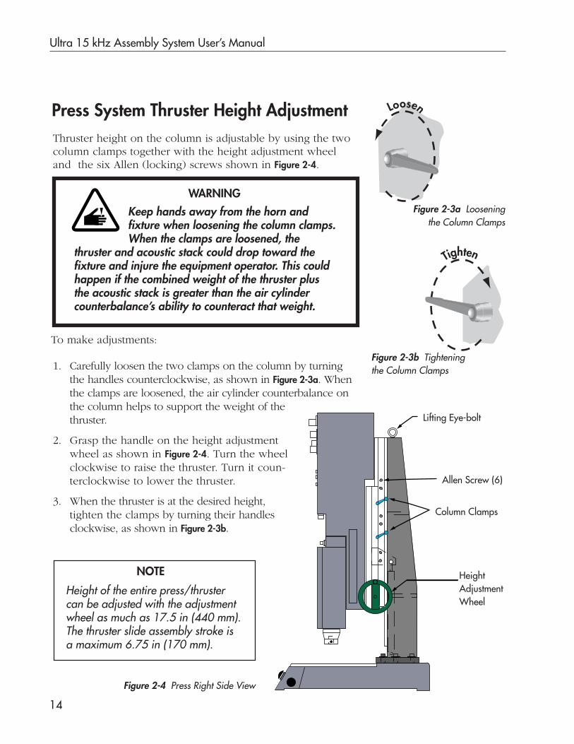
Thruster height on the column is adjustable by using the twocolumn clamps together with the height adjustment wheeland the six Allen (locking) screws shown in Figure 2-4.
1. Carefully loosen the two clamps on the column by turningthe handles counterclockwise, as shown in Figure 2-3a. Whenthe clamps are loosened, the air cylinder counterbalance onthe column helps to support the weight of thethruster.
2. Grasp the handle on the height adjustmentwheel as shown in Figure 2-4. Turn the wheelclockwise to raise the thruster. Turn it coun-terclockwise to lower the thruster.
3. When the thruster is at the desired height,tighten the clamps by turning their handlesclockwise, as shown in Figure 2-3b.
Press System Thruster Height Adjustment
Figure 2-3b Tighteningthe Column Clamps
WARNING
Keep hands away from the horn andfixture when loosening the column clamps.When the clamps are loosened, the
thruster and acoustic stack could drop toward thefixture and injure the equipment operator. This couldhappen if the combined weight of the thruster plusthe acoustic stack is greater than the air cylindercounterbalance’s ability to counteract that weight.
Lifting Eye-bolt
Column Clamps
HeightAdjustmentWheel
Figure 2-4 Press Right Side View
NOTE
Height of the entire press/thrustercan be adjusted with the adjustmentwheel as much as 17.5 in (440 mm).The thruster slide assembly stroke isa maximum 6.75 in (170 mm).
To make adjustments:
Allen Screw (6)
Figure 2-3a Looseningthe Column Clamps
Section 2 Installation
15
Press System Basic Cable Connections
Ground the SystemMake sure the system is properly grounded.
Is the system properly grounded? Before proceeding,make sure you have followed the instructions ofSection 1 relating to electrical grounding.
CAUTION
Continued
4. After all adjustments are made, tighten the 6 Allen (lock-ing) screws: 2 above the top column clamp, 2 between thecolumn clamps, and 2 below the bottom column clamp.
Thruster Height Adjustment, continued

Ultra 15 kHz Assembly System User’s Manual
16
Figure 2-5 Press System Cable Connections
240 VAC50/60 HZ
30A
J1
OPERATIONAL CONTROL
J20
J23
U.S. PATENT 4,277,710
U/S OUTPUT
DUKANE CORPST. CHARLES, ILU/S GENERATORMODEL 15A4000MADE IN USA
— WARNING —POWER MUST BEGROUNDED AT
OUTLET
DISCONNECTPOWERCORD
BEFOREREMOVING
COVER
STATUSRELAY
SE
RIA
L N
UM
BE
R
US
12
34
56
MO
DE
L
90000 15A4000 123456
DU
KN
E C
OR
PO
RA
TIO
NS
T. C
HA
RL
ES
, ILL
INO
IS U
SA
THRUSTER STROKEENCODER
J12
AUXILLARYJ5
SAFETY SWITCHESJ8
AUTO INPUTJ9 OPERATIONAL CONTROL
TO GENERATORJ6
OPERATIONAL CONTROLTO THRUSTER
J7
RS–232 SERIAL PORT–DECJ3
CHART REC.OUTPUT
J11
120 VOLT50/60 HZ0.5 AMP J14 J15
ULTRASOUNDTO THRUSTER
ULTRASOUNDFROM GENERATOR
— WARNING —REMOVE ALL POWER BEFORE CONNECTING
OR DISCONNECTING ANY CABLES WITHIN SYSTEM.REFER SERVICING TO QUALIFIED PERSONNELPOWER LINE MUST BE GROUNDED AT OUTLET
S E R I A L N U M B E R
US 123456
MODEL _ _ _ _ _ _ _ _ _ULTRACOM
DUKANE CORPORATIONST. CHARLES, IL 60174
MADE IN USA
43C350
J35
J3 J1
80–100 psiAir Supply
Ultr
asou
nd I
nput
Line
ar E
ncod
er (
optio
nal)
Ope
ratio
nal C
ontr
ol
J40
Part No. 200–1064
Coaxial RG11A/U
Part No. 200–1289
5–conductor cable
Part No. 200–417
Base Interface
8–conductor cable
Coaxial RG11A/U
Part No. 200–1289
12–conductor cable Part No. 200–418Part No. 200–1064
1
23
4
5
Cable Connectionsfor a Press System

Section 2 Installation
17
Table 2-2 Press System Basic Connections
1. Make the basic cable connections throughas shown in Figure 2-5 and as detailed below. Whenconnections are complete, the press/thruster, the Ultra-Com, and the generator will be interconnected.
2. Make any optional connections.
3. Connect any customer supplied equipment such asautomation, chart recorder or printer.
4. Complete basic connections with customer-suppliedair and electricity.
Connect the power cords last, but do not turn onthe power yet.
Before connectingor disconnecting
cables: Put front panel powerswitches for the Ultra-Comand the generator in the OFFposition; turn off electricalpower; and, remove ACpower cords from their re-ceptacles.
Press System, Connections, continued
1 5
**Cables are available in longer lengths through the DukaneSales Department. See Section 11 for contact information.
NOTE
Continued
CAUTION
CableNo.
PartNumber
CableType
Length(m) ** From To
1 200-417 5-conductorOil-resistant 2.4
J6Ultra-Com
Operational Control
J20Generator
Operational Control
2 200-1289 CoaxialRGIIA/U 3
J15Ultra-Com Ultrasound
from Generator
J1Generator
Ultrasound Out
3 200-1289 CoaxialRGIIA/U 3
J14Ultra-Com
Ultrasound to Thruster
J1Thruster
Ultrasound Input
4 200-418 12-conductorOil-resistant 2.4
J7Ultra-Com Operational
Control to Thruster
J3Thruster
Operational Control
5 200-1064 8-conductorOil-resistant 2.7
J8Ultra-Com
Activation Switches
J35Press Base

Ultra 15 kHz Assembly System User’s Manual
18
OPERATIONALCONTROL
TOP-OF-STROKESWITCH
J3 J40
GROUND
AIR IN U/S J1
– CAUTION –LOCK OUT VALVE MUST BE CLOSED AND SECURED
WITH PADLOCK BEFORE SERVICING THIS EQUIPMENT.
– WARNING –WELDING HEAD WILL EXTEND WHEN LOCK-OUT ACTIVATED.
KEEP HANDS AWAY FROM WELDING HEAD.
– WARNING –DISCONNECT POWER BEFORE
REMOVING COVER.
Compressed AirConnect a stable supply of clean, dry, compressed air to the airinlet at the back of the thruster as shown below. Make sure theair delivered to the thruster exceeds the expected output pres-sure and that it is in the range of 80 - 100 psi.
Press System,Connections, continued
Run the generator only after:• the ultrasound signal cable is connected, and• the transducer is installed in the thruster.
Otherwise an overload condition could occur, with possibledamage to the generator.
CAUTION
Figure 2-6 Thruster Air Inlet Detail
1/4 “ Air Inlet
Air Lockout Valve
Rear of Thruster

Section 2 Installation
19
Optional ConnectionsComplete cable connections for any optional features.
Linear Encoder
If your unit has the linear (distance) encoder, connect theencoder’s free end to connector J12, THRUSTER STROKE ENCODERon the back of the Ultra-Com. (See Pages 39-42 for more infor-mation about the encoder.)
Recheck ConnectionsRecheck all connections, and when they are all secure, you areready to connect electrical power.
Connect Electrical PowerAs a final step in the cabling of your system, connect electricalpower to the Ultra-Com and to the generator. See Section 12,Specifications, for input power requirements.
Press System, Connections, continued
Top-of-Stroke CableThis optional cable connects the thruster’s J40, TOP-OF-STROKESWITCH connector to the customer’s automation system. Theswitch in the thruster opens when the press/thruster slide assem-bly returns to the fully retracted, or top-of-stroke position. Thiscontact closure is typically used with automated systems to indi-cate to the controlling mechanism that the slide assembly is fullyretracted.
NOTE
Under normal use, we recommend that the maximum voltage andcurrent applied to the contacts do not exceed 24 VDC @ 2 amps.
Ultra 15 kHz Assembly System User’s Manual
20
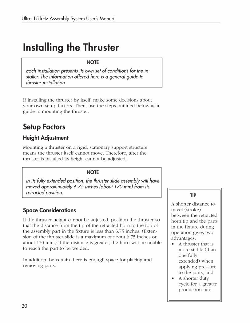
Installing the ThrusterNOTE
Each installation presents its own set of conditions for the in-staller. The information offered here is a general guide tothruster installation.
If installing the thruster by itself, make some decisions aboutyour own setup factors. Then, use the steps outlined below as aguide in mounting the thruster.
Setup FactorsHeight AdjustmentMounting a thruster on a rigid, stationary support structuremeans the thruster itself cannot move. Therefore, after thethruster is installed its height cannot be adjusted.
NOTE
In its fully extended position, the thruster slide assembly will havemoved approximiately 6.75 inches (about 170 mm) from itsretracted position.
Space ConsiderationsIf the thruster height cannot be adjusted, position the thruster sothat the distance from the tip of the retracted horn to the top ofthe assembly part in the fixture is less than 6.75 inches. (Exten-sion of the thruster slide is a maximum of about 6.75 inches orabout 170 mm.) If the distance is greater, the horn will be unableto reach the part to be welded.
In addition, be certain there is enough space for placing andremoving parts.
TIP
A shorter distance totravel (stroke)between the retractedhorn tip and the partsin the fixture duringoperation gives twoadvantages:• A thruster that is
more stable (thanone fullyextended) whenapplying pressureto the parts, and
• A shorter dutycycle for a greaterproduction rate.

Section 2 Installation
21
Connections for Thruster Only
Mounting the Thruster1. Place the back of the thruster onto the
support structure.Examples of this structure: a weldment, aframe, or a baseplate.
2. Align the thruster with thesupport structure. This can be done byusing the thruster bolt holes and/ordowel pin holes to align with boltholes and dowel pins of the supportstructure. See Figure 2-7.The thruster has three threadedmounting holes.
3. Insert three mounting bolts (3/8-16x 1-1/4" hexhead or equivalent)with flat washers, as shown in Figure2-7.
4. Adjust the thruster so the horn meetsthe fixture at the proper angle for your applcation.
5. Tighten the bolts.
Figure 2-7 Mounting the Thruster
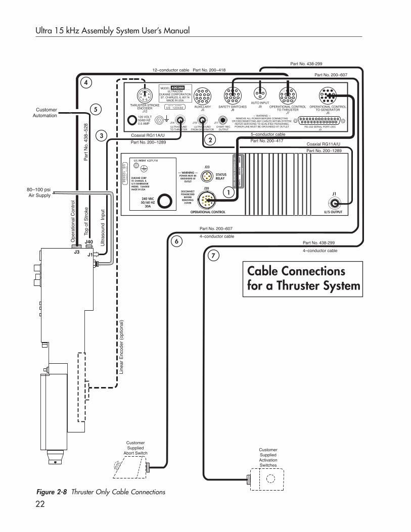
1. Make the basic cable connections throughas shown in Figure 2-8 and as detailed on the nextpage. When connections are complete, the thruster, theUltra-Com, and the generator will be interconnected.
2. Make any optional connections.
3. Connect any customer supplied equipment such asautomation, chart recorder or printer.
4. Complete basic connections with customer-suppliedair and electricity.
Connect the power cords last, but do not turn onthe power yet.
1 7 CAUTION
Dowel Pin Hole (2)
Washer
Horn
Fixture
Bolt
Support Structure
Continued
Before connectingor disconnecting
cables for any system com-ponent:Turn off electrical power.Remove power cords fromreceptacles.Put the front panel powerswitches for both the Ultra-Com and the generator inthe OFF position.
Ultra 15 kHz Assembly System User’s Manual
22Figure 2-8 Thruster Only Cable Connections
Cable Connectionsfor a Thruster System
240 VAC50/60 HZ
30A
J1
OPERATIONAL CONTROL
J20
J23
U.S. PATENT 4,277,710
U/S OUTPUT
DUKANE CORPST. CHARLES, ILU/S GENERATORMODEL 15A4000MADE IN USA
— WARNING —POWER MUST BEGROUNDED AT
OUTLET
DISCONNECTPOWERCORD
BEFOREREMOVING
COVER
STATUSRELAY
SE
RIA
L N
UM
BE
R
US
12
34
56
MO
DE
L
90000 15A4000 123456
DU
KN
E C
OR
PO
RA
TIO
NS
T. C
HA
RL
ES
, ILL
INO
IS U
SA
THRUSTER STROKEENCODER
J12
AUXILLARYJ5
SAFETY SWITCHESJ8
AUTO INPUTJ9 OPERATIONAL CONTROL
TO GENERATORJ6
OPERATIONAL CONTROLTO THRUSTER
J7
RS–232 SERIAL PORT–DECJ3
CHART REC.OUTPUT
J11
120 VOLT50/60 HZ0.5 AMP J14 J15
ULTRASOUNDTO THRUSTER
ULTRASOUNDFROM GENERATOR
— WARNING —REMOVE ALL POWER BEFORE CONNECTING
OR DISCONNECTING ANY CABLES WITHIN SYSTEM.REFER SERVICING TO QUALIFIED PERSONNELPOWER LINE MUST BE GROUNDED AT OUTLET
S E R I A L N U M B E R
US 123456
MODEL _ _ _ _ _ _ _ _ _ULTRACOM
DUKANE CORPORATIONST. CHARLES, IL 60174
MADE IN USA
43C350
J3 J1
80–100 psiAir Supply
Ultr
asou
nd I
nput
Line
ar E
ncod
er (
optio
nal)
Ope
ratio
nal C
ontr
ol
J40
Part No. 200–607
Coaxial RG11A/U
Part No. 200–1289
5–conductor cable
Part No. 200–417
CustomerSupplied
Abort Switch
4–conductor cable
Coaxial RG11A/U
Part No. 200–1289
12–conductor cable Part No. 200–418Part No. 200–607
1
23
4
6
Top
of S
trok
e
CustomerAutomation
Par
t No.
438
–528
CustomerSuppliedActivationSwitches
7
5
Part No. 438-299
4–conductor cable
Part No. 438-299

Section 2 Installation
23
Thruster Only, Connections, continued
CAUTION
NOTECables are available in longer lengths through the DukaneSales Department. See Section11 for contact information.
**
Table 2-3 Thruster System Basic Cable Connections
Run the generator only after:• the ultrasound signal cable is connected, and• the transducer is installed in the thruster.
Otherwise an overload condition could occur, withpossible damage to the generator.
CableNo.
PartNumber
CableType
Length(m) ** From To
1 200-417 5-conducorOil-resistant 2.4
J6Ultra-Com
Operational Control
J20Generator
Operational Control
2 200-1289 CoaxialRG11A/U 3
J15Ultra-Com Ultrasound
from Generator
J1Generator
Ultrasound Out
3 200-1289 CoaxialRG11A/U 3
J14Ultra-Com
Ultrasound to Thruster
J1Thruster
Ultrasound Input
4 200-418 12-conducorOil-resistant 2.4
J7Ultra-Com Operational
Control to Thruster
J3Thruster
Operational Control
5 438-528 2-conducorOil-resistant 2.7
J40Thruster
Top-of-StrokeUser SuppliedAutomation
6 200-607 4-conducorOil-resistant 2.7
J8Ultra-Com
Safety Switches
User SuppliedAbort Switch
7 438-299 4-conducorOil-resistant 2.7
J9Ultra-ComAuto Input
User SuppliedActivation Switches
Ultra 15 kHz Assembly System User’s Manual
24
Compressed Air ConnectionBecause the thruster does not use a support package, the airsource is connected directly to the “100 PSI AIR” fitting on theback of the thruster.
Make sure the air delivered is stable, clean, dry (free of anymoisture and lubricant), and between 80-100 psi.
Thruster Only, Connections, continued
Recheck ConnectionsRecheck all connections, and when they are all secure, you areready to connect electrical power.
Connect Electrical PowerAs a final step in the cabling of your system, connect AC electri-cal power to the Ultra-Com and to the generator. See Section 12,Specifications, for input power requirements.
NOTE
Compressed air must bedelivered at a higherpressure than the ex-pected output pressure,and in a range of 80 -100 psi.
NOTE
See the next page for a flange template to be used in mounting your unit to a baseplate.

Section 2 Installation
25
7.75 inches(196.85 mm)
FRONT
2.625 inches(66.675 mm)
2.625 inches(66.675 mm)
2.25 inches(57.15 mm)
2.25 inches(57.15 mm)
2.00
inch
es(5
0.80
mm
)
1.50
inch
es(3
8.10
mm
)
3.02
3 in
ches
(76.
783
mm
)
3.875 inches(98.425 mm)
REAR
Flange TemplateFigure 2-9 Base Flange Template (full scale)
Bolts: Use five 1/2” (12 mm) diameterwith appropriate length to hold the flange.

Ultra 15 kHz Assembly System User’s Manual
26
This page intentionally left blank

Dukane Corporation
SECTION 3
Controls and Indicators
• This section describes press/thrustercontrols and indicators.

Dukane Corporation
This page intentionally left blank

Section 3 Controls and Indicators
27
OverviewMaterial in this section describes the press/thruster controlsand indicators, and it explains what they do. Controls andindicators are presented in this section according to wherethey are found on the press/thruster:
• Front Panel,
• Rear Panel, or
• Press Base.
Figure 3-1 Standard Press Controls Locations
Press Base
Front Panel
Height AdjustmentWheel
Rear Panel
Column Clamps
Right Side ViewFront View
Ultra 15 kHz Assembly System User’s Manual
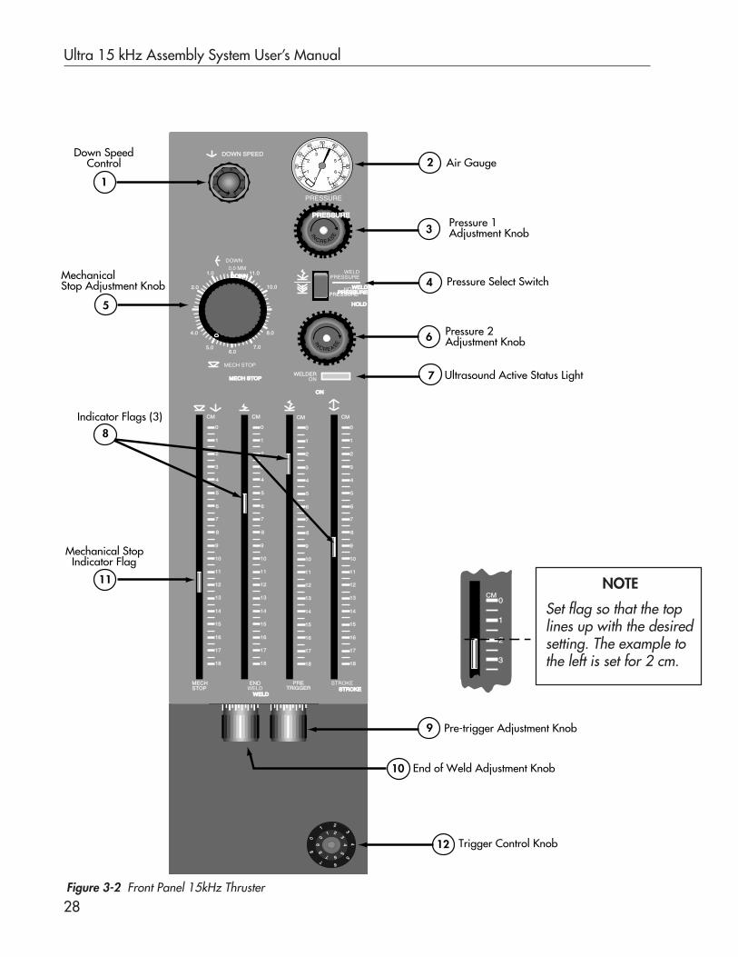
28Figure 3-2 Front Panel 15kHz Thruster
NOTE
Set flag so that the toplines up with the desiredsetting. The example tothe left is set for 2 cm.
MECH STOP
MECH STOP
DOWN
DOWN
DOWN SPEED
WELD
WELD
PRESSURE
PRESSUREHOLD
HOLD
PRESSURE
WELDERON
ON
MECH STOP
ENDWELD
WELD
PRETRIGGER
STROKESTROKE
0.0 MM
0.0 MM
1.0
2.0
4.0
5.06.0
7.0
8.0
10.0
11.0
5040
3020
10
60
7080
90
100
3 4
2
1
5
6
70
IN
C R E ASE
5
43
21 0
98
76
54
67
8
3
21
0
43
21
09
8
7 6
5
IN
C R E ASE
CM0
1
2
3
0
1
2
3
4
6
7
8
9
10
11
12
13
14
15
16
17
18
5
CM
0
1
2
3
4
6
7
8
9
10
11
12
13
14
15
16
17
18
5
CM
0
1
2
3
4
6
7
8
9
10
11
12
13
14
15
16
17
18
5
CM
0
1
2
3
4
6
7
8
9
10
11
12
13
14
15
16
17
18
5
CM
Down Speed Control
1
Air Gauge2
Pressure 1Adjustment Knob
4
Pressure 2Adjustment Knob
5
3
6
7
8
11
9
12
Pressure Select Switch
Ultrasound Active Status Light
Pre-trigger Adjustment Knob
Trigger Control Knob
10 End of Weld Adjustment Knob
MechanicalStop Adjustment Knob
Indicator Flags (3)
Mechanical Stop Indicator Flag
PRESSURE
PRESSURE
Section 3 Controls and Indicators
29
Front Panel
This control adjusts the downward velocity of the slideassembly (during Downstroke) by controlling the rate ofair exhaust from the lower part of the air cylinder.
Pull the red locking ring out to unlock the controlknob. Then, the plastic knob can be turned.
To increase velocity, turn the plastic knob counter-clockwise.
To decrease velocity, turn the plastic knob clockwise.When you are finished making adjustments, push in thered locking ring.
Down Speed Control (DOWN SPEED)
Air Gauge (PRESSURE)The gauge displays the amount of pressure beingapplied during the Weld and Hold portions of thecycle. The gauge registers pressure from both Pressure1 and Pressure 2 regulators respectively.
1
2
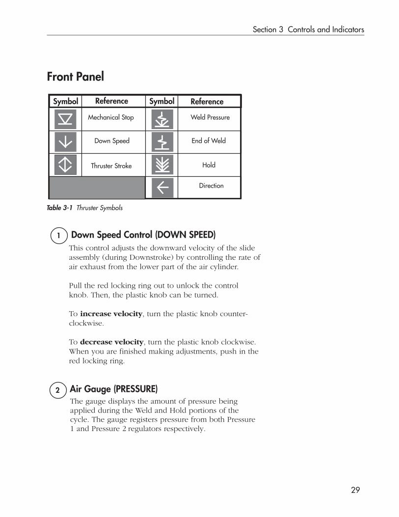
Reference
Weld Pressure
End of Weld
Hold
Direction
Symbol Reference Symbol
Mechanical Stop
Down Speed
Thruster Stroke
Table 3-1 Thruster Symbols

Ultra 15 kHz Assembly System User’s Manual
30
Pressure 2 Adjustment KnobPressure 2 is the pressure inside the air cylinder used duringthe Hold portion of the weld cycle. The adjustment knobconnects to a second air pressure regulator.To set Pressure 2:1. Press and hold the Pressure Select Switch button to HOLD
PRESSURE.2. Watch the PRESSURE gauge, and turn the knob clockwise
to increase pressure; turn it counterclockwise to decreasepressure.
3. When the air gauge shows the desired Hold pressure,Pressure 2 is set. Release the Pressure Select Switch.
5
3
Pressure 1 is the pressure inside the air cylinder used: as theslide assembly descends; during the Weld portion of thecycle; and, as the slide assembly retracts. The adjustmentknob connects to an air regulator.To set Pressure 1:
2. Watch the PRESSURE gauge needle, and turn the adjust-ment knob — clockwise to increase air pressure, andcounterclockwise to decrease air pressure.
3. When the air gauge displays the desired welding pres-sure, Pressure 1 is set.
Continued
Pressure 1 Adjustment Knob
4 Pressure Select Switch (WELD PRESSURE/HOLD PRESSURE)
This switch is used to select either the Weld Pressure (Pres-sure 1) regulator or the Hold Pressure (Pressure 2) regulator.This can be done to set the pressures and to montior them.
To move the stop (and also the indicator flag), turn theMechanical Stop Adjust knob: counterclockwise to lower it,and clockwise to raise it.
This provides a way to stop the slide:• at a particular depth of travel relative to the fixture, or• to prevent the horn from contacting the fixture when
there is no part present.
Mechanical Stop Adjustment Knob
6
1. The Pressure Select Switch button is normally in theWELD PRESSURE position.

Section 3 Controls and Indicators
31
Indicator FlagsThe flags can provide visual feedback for three aspects ofthe weld process: END WELD, PRE-TRIGGER, and STROKEPOSITION. Only the STROKE POSITION flag moves with theslide assembly itself.
To find out how far this slide assembly moves:When the slide is in its “up” or retracted position, notethe top edge of the middle flag is aligned with the “00”on the stroke position scale.Then, when the slide assembly is fully extended, notewhere the top of the flag is. That is the stroke distance.
See the EXAMPLE below.
When welding with dual pressure, both regulators areactive though at different times in the weld cycle. Pres-sure 1 regulator is active as the slide assembly descendsand during the Weld portion of the cycle. Pressure 2regulator is active as the Hold portion of the weld cycletakes place.
7 Ultrasound Active Status Light (WELDER ON)This light glows green whenever the ultrasound signalis applied to the stack.
EXAMPLEThe STROKE POSITION flag starts at the 0 mark on thescale. At the extension of the slide assembly, the posi-tion of the flag is at the 10 mark.Subtract 0 from 10, and the result is 10 centimeters. Thismeans that the slide assembly has moved 10 centimeters.
Continued
END WELD and PRE TRIGGER flags move when their corre-sponding adjustment knob is turned. Readings aretaken from the top edge of these flags.See and on the next pages for more information.9 10
8

Ultra 15 kHz Assembly System User’s Manual
32
When pre-trigger is not needed for an application, turn theknob so the indicator is at the bottom of its slot.
Turning the knob clockwise lowers the PRE TRIGGER flagincreasing the distance traveled before the ultrasoundsignal is turned on. The flag shows where the ultrasoundsignal will be turned on. The signal can start either beforethe horn contacts the assembly part or after contact ismade. As the horn descends, the ultrasound signal stayson until the weld controlling parameter (time, distance, orenergy) has been met or until the tops of the STROKEPOSITION and END WELD indicator flags are even.
9
Indicator Flags, continued
NOTE
To help establishreference points, ascale from 000 to 100has been put on thePre-trigger and EndWeld adjustmentknobs.
Continued
Pre-trigger Adjustment Knob
NOTE
Refer to the Ultra-Com User’s Manual as you decide on thetrigger settings. Make sure your Ultra-Com setup corresponds tothe mechanical adjustments you have made to the press itself.
Adjust the pre-trigger flag so the ultrasoundsignal will not start until the horn is 1/4 inch(7 mm) (or less) from the part to be welded.
CAUTION

Section 3 Controls and Indicators
33
End Weld Adjustment Knob10
Turning the knob moves the END WELD indicator flag.The top edge of the flag shows where the ultrasoundsignal will be turned off.
When the pre-trigger control is used to start the ultra-sound signal (as the horn descends), the end weld fea-ture can be used to shut off the ultrasound signal. As thehorn descends, it will reach the point where the STROKEPOS indicator flag is even with the END WELD indicatorflag. The ultrasound signal will shut off at that point.
When an application does not require the end weld fea-ture, position the END WELD flag at the bottom of its slot.
Pre-trigger Adjustment Knob, continued
NOTE
The End of Weld input for the Ultra-Com comes from the End ofWeld press indicator flag, and it is used to end the weld portion ofthe cycle based on the press head position. The flag can be manu-ally raised or lowered to end the weld at an absolute distance. TheEnd of Weld feature is generally not used with a press or thrusterequipped with a distance encoder.

Ultra 15 kHz Assembly System User’s Manual
34
TIPThe mechanical stop isused in two ways. Onswage and insertionapplications it is used tostop the weld at a par-ticular depth.On all other applica-tions, it is used to pre-vent the horn fromstriking the fixturewhen an assembly partis not in the fixture. Thisprevents possible dam-age to horn/fixture.
Indicator Flags, continued
11 Mechanical Stop IndicatorThis indicator shows where the mechanical stop has beenset. The stop ends the press downstroke preventing theslide assembly from moving beyond that point.
Trigger Control Knob
This control allows the operator to select what “preload”or amount of force will be applied to a part before theultrasound signal is turned on.A pressure switch in the slide assembly closes when aspecific amount of force applied to the horn is reached.
The trigger control adjusts the amount of force needed toclose that pressure switch. When the switch closes, the ultra-sound signal starts, and the horn begins to vibrate.
See Figure 3-3 for trigger knob detail.To make adjustments, grasp the inner knob, and turn it tomake adjustments. This knob can be turned as many asnine revolutions. Each revolution advances the outer dialone number in the direction the knob was turned. A leverbetween the scales locks the control in position.
The numbers on the scale give the operator only a relativereading. A higher setting indicates more preload force (onthe part before the ultrasound signal is turned on). A lowersetting means less force. Figure 3-3 Trigger Control Knob
NOTEWhen a press has a load cell (force transducer), the trigger controlknob is not used. The compression force is set electronically. Refer tothe Ultra-Com User’s Manual for “Trigger Type, Force.”
12
7
12
3
4
6
8 5
0 0
1 2 3
45
678
9
Locking Lever

Section 3 Controls and Indicators
35
Rear PanelThe air handling apparatus is accessible from the press rearpanel. The figure below provides some detail for the airlockout valve.
Figure 3-4 Rear Press Panel
NOTE
The customer supplies the necessary air handling compo-nents for the thruster. See Page 24 for thruster’s CompressedAir Connection.
Air Lockout Valve
Valve Slidein Open Position
Compressed AirConnection
OPERATIONALCONTROL
TOP-OF-STROKESWITCH
J3 J40
AIR IN U/S J1
– CAUTION –LOCK OUT VALVE MUST BE CLOSED AND SECURED
WITH PADLOCK BEFORE SERVICING THIS EQUIPMENT.
– WARNING –WELDING HEAD WILL EXTEND WHEN LOCK-OUT ACTIVATED.
KEEP HANDS AWAY FROM WELDING HEAD.
– WARNING –DISCONNECT POWER BEFORE
REMOVING COVER.
Ultra 15 kHz Assembly System User’s Manual
36
C L O S E D
Valve Slide
C L O S E D
O P E N
(Air Line Removed)Side View
Valve in Closed Position
Put Padlock or Cable Lock Through this Hole
Thruster
Valve in Open Position
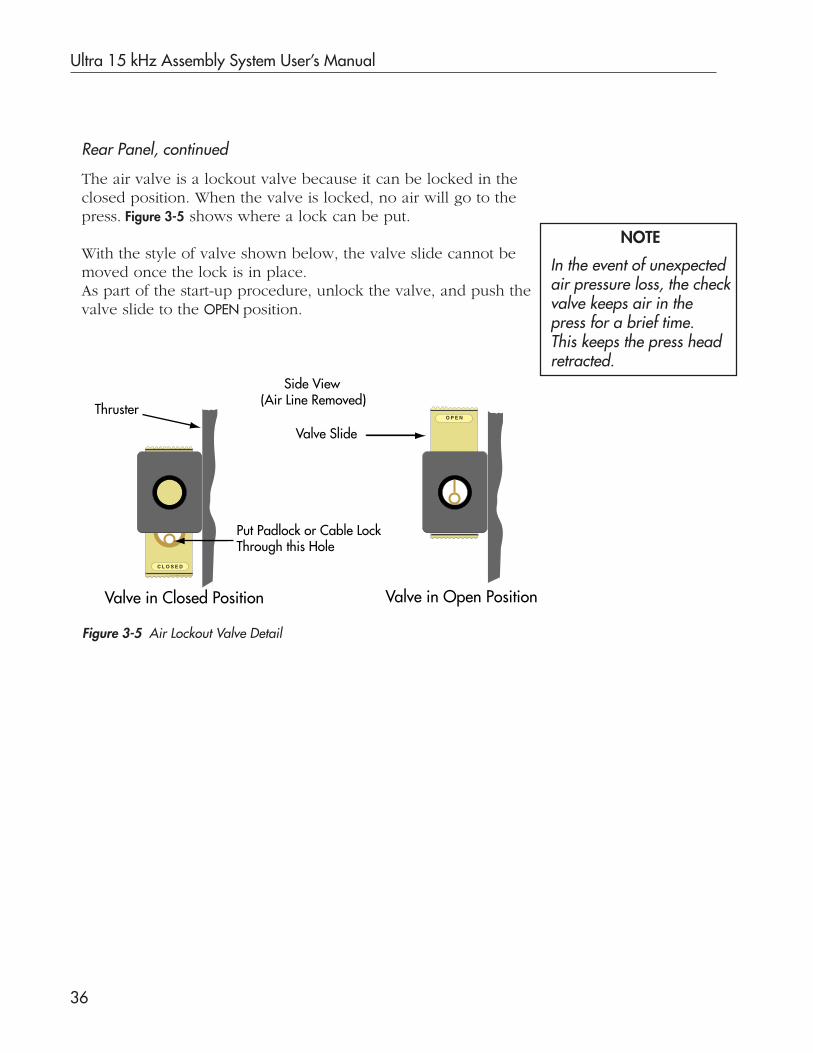
The air valve is a lockout valve because it can be locked in theclosed position. When the valve is locked, no air will go to thepress. Figure 3-5 shows where a lock can be put.
With the style of valve shown below, the valve slide cannot bemoved once the lock is in place.As part of the start-up procedure, unlock the valve, and push thevalve slide to the OPEN position.
Figure 3-5 Air Lockout Valve Detail
NOTE
In the event of unexpectedair pressure loss, the checkvalve keeps air in thepress for a brief time.This keeps the press headretracted.
Rear Panel, continued

Section 3 Controls and Indicators
37
Press Status(LED) Display
PUSH FOREMERGENCY OFFSwitch (Red)
Right Activation Switch
Base Plate
LeftActivationSwitch
(Black)
(Black)
Press BaseThe ergonomic base, shown in Figure 3-6, consists of a baseplate, cycle activation switches (black palm buttons), PUSH FOREMERGENCY OFF switch (red palm button), and a status displayscreen. At the back of the base is a cable connector for aninterface between the Ultra-Com and the base front panel.
Figure 3-6 Press Ergonomic Base
Base Plate
The base plate is bolted to the top of the ergonomic base. Itcontains drilled and tapped holes that line up with levelingscrews in the fixtures. This allows for easy fixture leveling andalignment with the horn. For details on the alignment andleveling of the fixture, see Fixture Installation, Pages 54-56.
Emergency OFF Switch
The PUSH FOR EMERGENCY OFF switch applies 24 vdc power tothe thruster/press. If the switch is pushed in, the Ultra-Comand the generator begin the following procedure:• Turns off the ultrasound signal immediately,• Removes the electrical power from the press, and• Initiates a software abort sequence.

Ultra 15 kHz Assembly System User’s Manual
38
Activation Switches
To initiate a weld cycle, both the left and right activationswitches must be pushed “on” within 350 milliseconds (ms) ofeach other and held closed for at least 25 ms. This is amandated safety requirement.
Press Status Display
The display shows one of three press status conditions:
• READY - When the PUSH FOR EMERGENCY OFF switch istwisted and then pulled out, the green READY status lightindicates that power is applied to the press. The press isready for operation.
• ABORT - When the PUSH FOR EMERGENCY OFF switch ispushed in, the red ABORT status indicator lights up.Press operation is no longer possible.
• IN CYCLE - When both left and right activation switchesare pressed, IN CYCLE lights up on the press status displayfor as long as the palm switches are activated.

Dukane Corporation
SECTION 4
Press Options
• This section provides information onthe common options available forthe press.

Dukane Corporation
This page intentionally left blank

Section 4 Press Options
39
OverviewThis section provides information for several commonoptions:
• Linear Encoder,• Electronic Pressure Regulator,• Pressure Transducer, and• Force Transducer.
Continued
Linear Encoder
PurposeThe linear encoder accurately mea-sures the distance travelled by theslide assembly and ensures that slideassembly movement can be pre-cisely controlled and monitored.
An optional device for your Ultra 15 kHz Assembly System isthe linear encoder, also known as the distance encoder. Itmay have come with the original system purchase, or it mayhave been purchased as an “add-on” after the initial systeminstallation had been made.
ComponentsThe linear encoder kit, P/N 438-846.consists of:
• encoder scale,• encoder head and mounting plate• modified right side press panel, and• mounting hardware.
NOTEThe Ultra-Com thatcontrols the systemmust have the “Dis-tance” option for theencoder to operate.
Linear Encoder Scale(movable)
Encoder Head(stationary)
To Ultra-Com J12
Figure 4-1 Linear Encoder Components

Ultra 15 kHz Assembly System User’s Manual
40
ThrusterCasting
Encoder Cable
Cable Clamp (2)
Top-of-StrokeSwitch Bracket
Black Bracket
Installing the Linear Encoder KitRemove Standard Right Side Panel
1. Close and lock the air lockout valve. (See Page 36.)2. Turn off the Ultra-Com and the generator. That leaves the
press without power.3. Remove the right side panel (with the DUKANE Ultra logo
on it) from the press.4. Remove the side cover held by 2 flat-head screws. Save the
screws.5. If a top-of-stroke switch is supplied, remove it from its switch
bracket. Then remove the switch bracket from the casting.
Linerar Encoder, continued
Figure 4-2 Linear Encoder Mounting Detail
NOTEThe encoder scale and head are joined, so please, do notattempt to separate them unless directed to do so.
Install Kit Components
1. Attach the new black bracket to the thruster casting using two#10-32 x 3/8” pan head screws. (If you removed the top-of-stroke switch bracket, you can use the screws saved in Step 5above.) Place the new black bracket on the casting, and putthe top-of-stroke switch bracket on top of the black bracket.Secure the bracket(s) with the screws.
2. Apply Loctite to the threads of two #10-32 x 1/2” flat headscrews. Attach the rectangular machined aluminum plate tothe lower part of the thruster casting using those screws.
3. Put the stationary encoder head on top of the aluminum plateso its top and bottom holes line up with matching holes inthe plate. Temporarily attach the encoder head with two #6-32 x 3/4” pan head screws and washers. Screws will betightened later during alignment.
4. Secure the encoder cable to the black bracket using twonylon cable clamps, two #10-32 lock washers, and two #10-32nuts. Loosen (or remove) the presss support panel (if sup-plied), and feed the cable and connector through the notch inthe thruster casting. Use “edge guard” to protect the cablefrom any sharp edges on the press support sheet metal.

Section 4 Press Options
41
Alignment
Aligning the linear encoder sets the internal referencemark for the encoder. This reference mark resets thedistance register in the Ultra-Com after each cycle,and ensures repeatable distance measurements fromcycle to cycle.
1. Align the encoder scale with the encoder head sothat a 1 mm (.039”) gap exists between themalong the entire stroke range. Because this is acritical measurement (in prolonging the life of theoptical linear encoder) use a feeler gauge tocheck the gap width.
2. Check to see that the thruster slide moves up anddown without interference. Adjust encoder head andbody as necessary. After making final adjustments,tighten all screws.
Installing Linear Encoder Kit, continued
Figure 4-3 Linear Encoder Alignment
Continued
WARNING
Keep hands and clothing away from the presswhen it is activated.
Gap 1 mm(.039")
ThrusterCasting
EncoderHead
EncoderScale
Scale MountingPlate
EncoderCable
5. Remove the encoder head, and allow it to hang free.Attach the new scale mounting plate to the casting usingthe screws saved when the standard thruster side panelwas removed. Use Loctite or a comparable adhesive onthe screw threads.
6. Again attach the encoder head to its aluminum plate.Remove the screw that holds the stationary encoder headto the (movable) encoder scale. Carefully slide theencoder scale so its top and bottom holes matchwith holes in the scale mounting plate. Use two #8-32 x 5/8” pan head screws to attach the encoderscale to the plate.
Ultra 15 kHz Assembly System User’s Manual
42
b. If, after running one cycle, the encoder position readspositive (+.xxx), loosen the two encoder head screws, andslide the head down until the reading goes negative(-.xxx). Secure the two screws. Proceed to Step 6.
6. Set the gap between the encoder scale and head, using a.039 inch (1 mm) feeler gauge blade.
7. Measure the gap at the top and bottom of the stroke. Allow-able tolerance, as specified by the encoder manufacturer, is±.005 (range from .034 to .044 inches or .864 to 1.12 mm).
8. Loosen and tighten all the screws as necessary, and check themeasurements again after tightening them.
Linear Encoder Alignment, continued
Testing 1. Unlock the padlock used on the air lockout valve.
2. Connect the encoder cable to connection J12 at the rear ofthe Ultra-Com (THRUSTER STROKE ENCODER).
3. Turn on the Ultra-Com. This restores power to the press aswell. Set the Ultra-Com to measure distance.
4. Set the air pressure to the desired level.
5. Perform the following procedure to test the encoder for theproper setting:
a. Run one weld cycle. If the encoder position reads nega-tive (-.xxx) then the encoder is above the “0” referencepoint used to measure distance by the Ultra-Com. This isthe correct setting. Secure the two screws on the encoderhead, and proceed to Step 6.
xxx = approximately -.125 to -.250
Attach Side Panel
Install the modified right side panel with its five (5) 1/4 turnretaining pins. Route the encoder cable through the notch in thethruster’s aluminum casting.
Connect the cable to the J12 connector on the Ultra-Com.

Section 4 Press Options
43
Electronic Pressure RegulatorThe electronic pressure regulator, (I/P transducer) is anelectro-pneumatic replacement for the manually adjusted airregulator on the press. The I/P transducer converts electricalsignal current (I) into air pressure (P). The Electronic Regula-tor takes an electrical signal sent by the Ultra-Com, andconverts it to the programmed air pressure.
The pressure value settings, “Pressure 1” (P1) and “Pressure 2”(P2), are stored in the Process Setup under Pressure in the Ultra-Com. P1 and P2 are set in pounds per square inch (PSI), orBARS.
To monitor Pressure 1 and Pressure 2 values, use the CHECKPRESSURE parameter, contained in the Utilities menu underUser Parameters (on the Ultra-Com).The Ultra-Com uses a pressure transducer to measure the I/Poutput pressures.
CalibrationThe I/P transducer installed in this thruster/press does notrequire on-site calibration. The unit is equipped with self-correcting, closed-loop circuitry.
Pressure TransducerThe pressure transducer (P/I transducer) performs the samefunction as the air gauge on the press. The P/I transducerconverts the air pressure (P) to an electrical signal current (I).It then sends the signal to the Ultra-Com. The Ultra-Comdisplays this signal as pressure.
Two sets of upper and lower limits can be monitored withthe pressure transducer:• One set of limits is used to monitor the air pressure before
a cycle starts. Using the bad parts limits, the unit will notbegin a cycle if the air pressure is outside the pressurewindow that has been set.This set of limits is used toensure that air pressure from the input line has notdropped below the pressure required for an acceptableweld force.
Continued

Ultra 15 kHz Assembly System User’s Manual
44
• The other set of limits is used to monitor the air pressurewhen the ultrasound is turned on.
This feature can be used as an indicator when checking for atrigger or load cell malfunction.
A more precise method to monitor trigger force is to use a load cell.
Calibration
The pressure transducer does not require any on-site calibration.
Load CellA load cell (force transducer) is a device that measures force.The load cell converts mechanical force into an electrical signal.The load cell monitors the force applied to the part. It sends asignal to the Ultra-Com to indicate when the mechanical pres-sure is equal to the programmed “Trigger Force”. The trigger isthe point at which the ultrasound is turned on.
The Trigger Force parameter can be viewed from the Utilitiesmenu with the Ultra-Com. Choose USER PARAMETERS, then chooseTRIGGER FORCE. The values for this parameter are in pounds orNewtons.
A force versus time graph can be generated if a printer is con-nected to the Ultra-Com.
Load Cell CalibrationThe load cell is calibrated at the factory. It does not require anyon-site calibration.
Pressure Transducer, continued

Dukane Corporation
SECTION 5
Stack/Fixture Setup
• This section outlines steps needed toremove and assemble an acoustic stack.It also discusses fixture installation.

Dukane Corporation
This page intentionally left blank

Section 5 Stack/Fixture Setup
45
OverviewThe Dukane Ultra 15 kHz Assembly System is used to assembleparts in a wide variety of applications. The ease with whichacoustic stack components can be installed and exchanged helpsmake this possible. In addition, this flexibiltity makes regularinspections and maintenance of the stack easier to perform.
This section tells how to change stack components. Removingthe stack, disassembly, assembly and installing the stack arecovered. The information applies to a first-time installation aswell as when a change to an existing setup is called for.
Stack DescriptionThe stack consists of three primary components (see Figure 5-1):
• Transducer,• Booster, and• Horn.
For an original equipment system, the transducer and boosterare usually shipped assembled and installed in the thruster.The horn, horn tips, and fixture are shipped separately.
Figure 5-1 Stack Components
Contact ButtonHORN
BOOSTER
Spanner Wrench Hole (typical)
TRANSDUCER
Mounting Ring
Transducer Housing
Mounting Std

Ultra 15 kHz Assembly System User’s Manual
46
Booster
Horn
Assembly
Disassembly
MountingStud
MountingStud
SpannerWrench
Hole(Typical)
BoosterMounting
Ring
TransducerHousing
UltrasoundContact Button
Input End
Input End
Output End
Output End(Threads Deeper Than Input End)
(Threads Shallower Than Output End)
Changing Stack Components
Figure 5-2 Stack Disassembly and Assembly
Figure 5-2 gives an illustrated overview of stack component disas-sembly and assembly.

Section 5 Stack/Fixture Setup
47
Stack Removal1. Push the PUSH FOR EMERGENCY OFF button on the front of
the press base.
2. Turn off power to the generator and to the Ultra-Com.
These two steps are necessary to insure that no power wouldbe accidentally applied while removing the stack.
3. While supporting the stack with one hand, loosen the twosocket head bolts that secure the stack access door.
4. Swing the access door open, and pull the stack towardyou until the transducer and booster mounting rings clearthe stack housing monting ring slots.
5. Pull the stack forward and down until the transducercontact button clears the press/thruster electrical contactleaf. Refer to Figure 5-3.
6. Lift the stack out of the housing.
NOTE
When changing or inspecting any of the stack components,ALWAYS remove the stack from the thruster.
Stack ContactButton:DO NOT TOUCHwhen removingstack.
Figure 5-3 Stack Removal
CAUTIONWhen opening or closing the stack accessdoor, support the stack by the horn or theexposed part of the booster This will keep itfrom falling and from being damaged. The
access door holds the stack in place when it is closed.
WARNINGElectrical Shock Potential!Do not touch the contact button when removingthe stack. There may be an electrical charge
stored in the transducer. (See “Explanation”, next page.)
NOTE
Press/thrusterElectrical ContactLeaf.DO NOT TOUCH.
BoosterMountingRing
Continued

Ultra 15 kHz Assembly System User’s Manual
48
Electric Shock Potential Explanation
Transducer performance depends on the nature of its piezoelectricmakeup. Electrical energy is converted to mechanical energy whenthe stack is in use inside a press/thruster. After the press has beenturned off, and handling the stack becomes necessary, keep inmind that any electrical charge that has built up inside the trans-ducer will discharge from the contact button. So, when removing astack from the press/thruster, do not touch the transducer’s contactbutton. Set the transducer aside. Wait a few minutes, and usuallythe charge will dissipate completely.
Once removed from the press/thruster, the transducer is capable ofconverting mechanical energy to an electrical charge.
For instance, electrical energy might be produced if the transducerexperiences a change in temperature or if the transducer receives aphysical blow of some kind. Again, any electrical charge thatresults from these kinds of mechanical forces would be focused atthe contact button.
Receiving a transducer shock would be similar to a shock you mayexperience when touching a household light switch after crossing acarpeted floor.
Stack Removal, continued

Section 5 Stack/Fixture Setup
49
Stack DisassemblyUse the two spanner wrenches (wrenches A and B) providedwith the press. To separate the stack components, read andcarefully follow the instructions below:
1. Place wrench A on the component to be removed, andplace wrench B on the component next to it. Refer toFigure 5-4.
2. Turn wrench A in the direction indicated.
3. When the component is loose, it can be removed by hand.
To maintain structural integrity, when separating componentsNEVER hold a transducer by the housing or the booster by itsmounting rings. Doing so will damage the holding pins inboth the transducer and the booster.
Use only the tools recommended by Dukane. NEVER clamp ahorn, booster, or transducer in a vise or use tools such aspliers, visegrips, etc. Doing so will scratch and/or gouge thesurfaces and introduce stress risers in the stack. The irregularsurfaces would affect the stack operation, and that could leadto failure of each stack component. The stress risers could de-velop into cracks causing the stack components to fail.
Figure 5-4 Stack Disassembly
A
B
CAUTIONAvoid injury when using the spannerwrench(es). Press down with the palm ofthe hand on the wrench handle.
NOTE
NOTE

Ultra 15 kHz Assembly System User’s Manual
50
Stack Assembly
Before assembling a stack, inspect all of the components forpossible damage. Take a few moments to inspect the surfacesto be joined. They should be smooth and clean.Look for surfaces that are uneven (concave, convex), havestress cracks, chips, or gouges. Any of these irregularities willaffect the operation of the stack, and could cause furtherdamage. Refer to Section 9 – Maintenance, for steps to take incleaning or smoothing the mating surfaces.
If the components have no damage, continue with the fol-lowing steps:
NOTE
A pitted surface or one that has a buildup of old grease anddirt, will interfere with the transfer of energy from one com-ponent to another.
1. Remove any foreign matter from the threaded stud andthe mating hole.
2. Put a thin coat of high-pressure grease (A small packet issupplied with the system.) on one of the mating surfaces.If high-pressure grease is not available, then use a thincoat of petroleum jelly.
Do not apply grease or lubricant to the stud or to its corre-sponding mating hole.
3. Thread the components together, and tighten them(Figure 5-6) by applying torque as follows:
Figure 5-5 Assembling StackComponents
250 inch-pounds = 20.8 foot-pounds, or28.2 Newton-meters.
Preassembly Check
Do not overtighten. Overtightening compo-nents can cause stress cracks, stud loosening,or unexplained power supply overloading.
CAUTION
Continued
NOTE
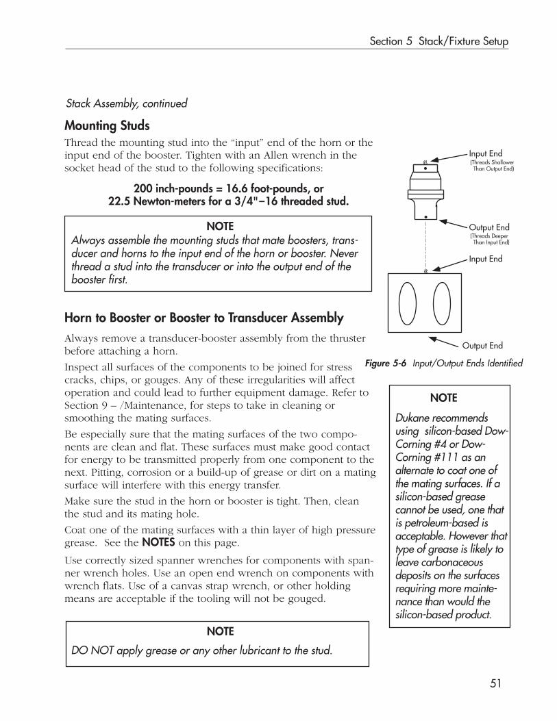
Section 5 Stack/Fixture Setup
51
Thread the mounting stud into the “input” end of the horn or theinput end of the booster. Tighten with an Allen wrench in thesocket head of the stud to the following specifications:
200 inch-pounds = 16.6 foot-pounds, or22.5 Newton-meters for a 3/4"–16 threaded stud.
Always assemble the mounting studs that mate boosters, trans-ducer and horns to the input end of the horn or booster. Neverthread a stud into the transducer or into the output end of thebooster first.
Always remove a transducer-booster assembly from the thrusterbefore attaching a horn.
Inspect all surfaces of the components to be joined for stresscracks, chips, or gouges. Any of these irregularities will affectoperation and could lead to further equipment damage. Refer toSection 9 – /Maintenance, for steps to take in cleaning orsmoothing the mating surfaces.
Be especially sure that the mating surfaces of the two compo-nents are clean and flat. These surfaces must make good contactfor energy to be transmitted properly from one component to thenext. Pitting, corrosion or a build-up of grease or dirt on a matingsurface will interfere with this energy transfer.
Make sure the stud in the horn or booster is tight. Then, cleanthe stud and its mating hole.
Coat one of the mating surfaces with a thin layer of high pressuregrease. See the NOTES on this page.
NOTE
DO NOT apply grease or any other lubricant to the stud.
Stack Assembly, continued
Mounting Studs
Horn to Booster or Booster to Transducer Assembly
Figure 5-6 Input/Output Ends Identified
Use correctly sized spanner wrenches for components with span-ner wrench holes. Use an open end wrench on components withwrench flats. Use of a canvas strap wrench, or other holdingmeans are acceptable if the tooling will not be gouged.
NOTE
Input End
Input End
Output End
Output End(Threads Deeper Than Input End)
(Threads Shallower Than Output End)
NOTE
Dukane recommendsusing silicon-based Dow-Corning #4 or Dow-Corning #111 as analternate to coat one ofthe mating surfaces. If asilicon-based greasecannot be used, one thatis petroleum-based isacceptable. However thattype of grease is likely toleave carbonaceousdeposits on the surfacesrequiring more mainte-nance than would thesilicon-based product.
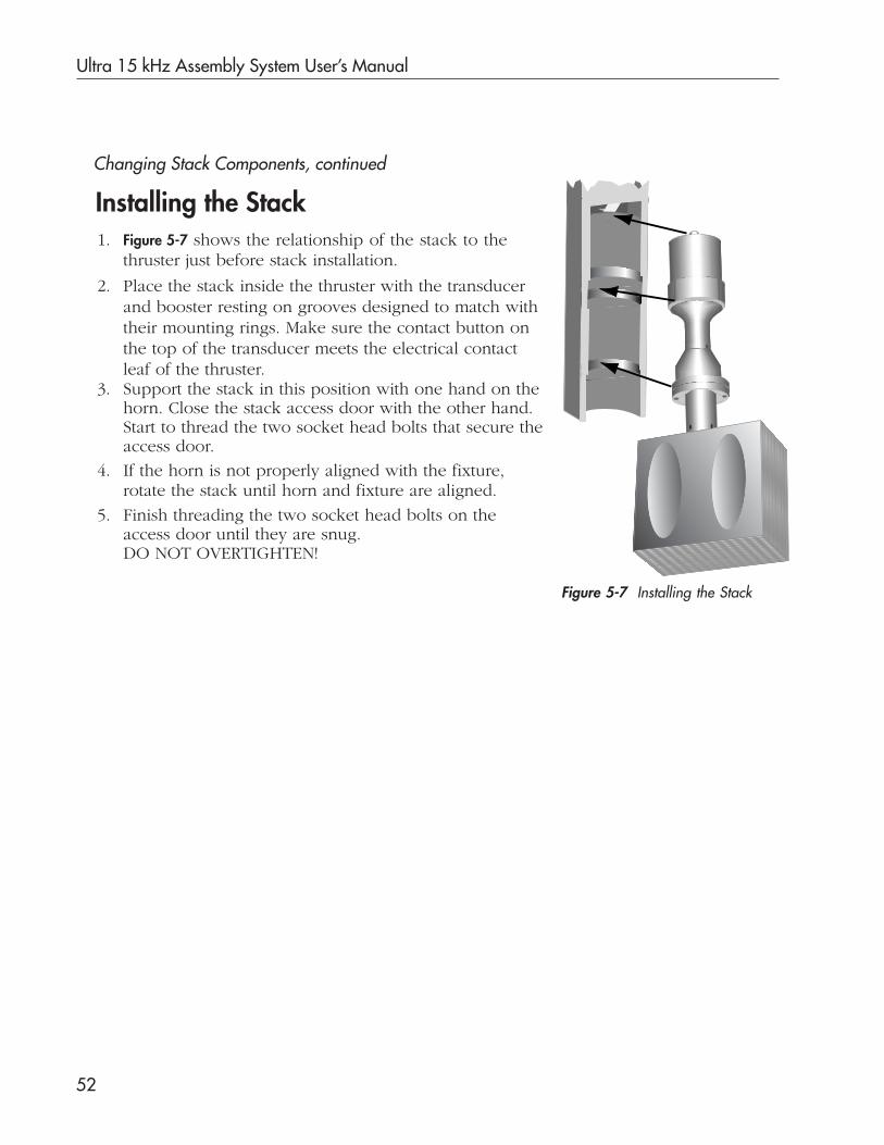
Ultra 15 kHz Assembly System User’s Manual
52
Changing Stack Components, continued
Installing the Stack
Figure 5-7 Installing the Stack
1. Figure 5-7 shows the relationship of the stack to thethruster just before stack installation.
2. Place the stack inside the thruster with the transducerand booster resting on grooves designed to match withtheir mounting rings. Make sure the contact button onthe top of the transducer meets the electrical contactleaf of the thruster.
3. Support the stack in this position with one hand on thehorn. Close the stack access door with the other hand.Start to thread the two socket head bolts that secure theaccess door.
4. If the horn is not properly aligned with the fixture,rotate the stack until horn and fixture are aligned.
5. Finish threading the two socket head bolts on theaccess door until they are snug.DO NOT OVERTIGHTEN!

Section 5 Stack/Fixture Setup
53
Fixture InstallationTo install a fixture, you need to do three things:
1. Align the fixture with the horn.2. Level the fixture to provide the necessary support.3. Secure the fixture to the mounting surface.
Fixture AlignmentTo safely align the fixture under thehorn, use the following procedure.Refer to Figure 5-8 and Figure 5-9.
1. Press the PUSH FOR EMERGENCEY OFFswitch on the press base. Thisallows the acoustic stack assem-bly to be lowered by hand whilepreventing the system fromaccidentally cycling.
2. Turn off the power to thegenerator and to the Ultra-Comto prevent accidental ultrasoundoperation.
3. Place the fixture, including theparts to be assembled, under the horn.
4. Initially align the two fixture slots over two of the eightmounting holes (size: M10-1.5), located on the base plate.
5. Install the two hold down bolts with washers.Finger tighten them.
Continued
Mounting Holes (8 Places) M10-1.5
CornerHold DownCap Screws(4 Places)
Hold Down Bolts
Fixture
NOTEThe fixture should be flat on the base. If the fixture is equippedwith leveling screws, adjust the screws so that they do notinterfere with the seating of the fixture on the base plate.
EmergencyOFF Switch
Figure 5-8 Fixture Installation
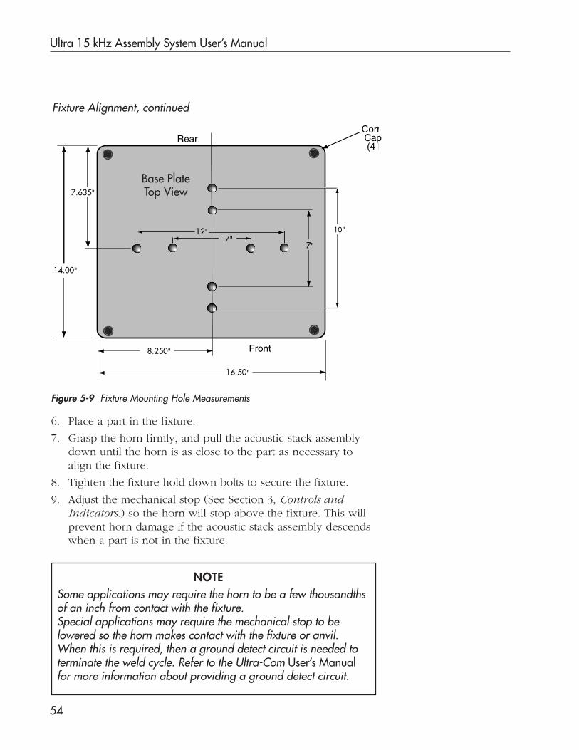
Ultra 15 kHz Assembly System User’s Manual
54
Fixture Alignment, continued
6. Place a part in the fixture.
7. Grasp the horn firmly, and pull the acoustic stack assemblydown until the horn is as close to the part as necessary toalign the fixture.
8. Tighten the fixture hold down bolts to secure the fixture.
9. Adjust the mechanical stop (See Section 3, Controls andIndicators.) so the horn will stop above the fixture. This willprevent horn damage if the acoustic stack assembly descendswhen a part is not in the fixture.
Figure 5-9 Fixture Mounting Hole Measurements
Some applications may require the horn to be a few thousandthsof an inch from contact with the fixture.Special applications may require the mechanical stop to belowered so the horn makes contact with the fixture or anvil.When this is required, then a ground detect circuit is needed toterminate the weld cycle. Refer to the Ultra-Com User’s Manualfor more information about providing a ground detect circuit.
NOTE
12"7"
7"
Corn Cap (4 P
10"
Rear
Front
7.635"
8.250"
14.00"
16.50"
Base PlateTop View
Section 5 Stack/Fixture Setup
55
Leveling the FixtureThe following procedure may be helpful, in some applica-tions, in leveling the fixture. To perform this procedure, you’llneed a piece of carbon paper and a piece of white paper.
1. Put a sample part in the fixture.
2. Place a piece of white paper on top of the sample part.
3. Place a piece of carbon paper, carbon side down, on topof the white paper.
4. Enter the following into the Ultra-Com:Weld time = 0.05Hold Time = 0.00Pressure = 20-40 psiSystem parameters = Use default settings.
5. Set the trigger control, on the thruster, so the pressureswitch closes after some pressure is applied.
6. Turn on the power to the generator and to the Ultra-Com.
7. Make sure the Mode Selection Keyswitch on the Ultra-ComFront Panel is in the OPERATE position.
8. Cycle the equipment, normally, by depressing the left andright base activation switches or by triggering the automa-tion switch.
When one cycle is complete, the pressure developed betweenthe horn and the sample part will have left marks from thecarbon paper on the white paper. If the fixture is not level,the carbon markings will be darker in some areas than inothers. All carbon markings will be uniform when all theproper adjustments have been made.
Make adjustments, and repeat this procedure as necessaryuntil you are confident that the fixture is level.

Ultra 15 kHz Assembly System User’s Manual
56
This page intentionally left blank

Dukane Corporation
SECTION 6
4000 Watt Generator
• This section describes the connections andcontrols for the ultrasonic generator.

Dukane Corporation
This page intentionally left blank

Section 6 4000 Watt Generator
57
4000 Watt GeneratorOverviewThe 4000 Watt generator converts 60 Hz/240 Volts AC powerinto a 15,000 Hz signal with an amplitude exceeding 1,000 volts.This signal is fed through the Ultra–Com unit which controls it,to the horn assembly in the thruster/press.
Safety ConsiderationTo avoid possible injury and to operate the equipment in a safeand efficient manner, please observe the following safety mea-sures. Note that some of the items are also applicable to systemcomponents other than the generator, such as the acoustic stackassembly or ultrasonic press.
• Do not operate any system components before theyare properly installed.
• Do not make any unauthorized modifications to thecontrol circuitry or other parts of the system. Thiscould cause damage to the equipment and/or injuryto the operator. Unauthorized modifications may alsovoid the equipment’s warranty.
• Do not operate this equipment without a properlygrounded connection.
• Accessories may be required for compliance with ap-plicable OSHA regulations for machine guarding andnoise exposure.
• When ultrasonic plastic welding equipment is usedwith automatic material handling equipment such asan automated system, a SYSTEM ABORT SWITCHshould be used and located at each operator station.
• Do not use of a foot switch in place of dual pushbutton switches. This violates OSHA regulations.
• The Ultra 15 kHz Assembly System will produce au-dible frequencies. Ear protectors may be worn to re-duce annoyance or discomfort from the resultingsound. In addition, sound baffles, sound enclosures,or acoustical absorbing material may also be needed.

Ultra 15 kHz Assembly System User’s Manual
58
Safety Considerations, continued
Electrical Safety Grounding InstructionsThe power cord used on the Dukane generator Ultra 4000(Dukane Part Number: 15A4000) is equipped with an in-lineconnector assembly.
The cord must be rated for at least 30 Amps at 240 VAC with apower line frequency of 50/60Hz.
For your safety and for the safety of others, the power recep-tacle must be grounded. If there is any question as to whetheror not the receptacle is properly grounded, please have itchecked by a qualified electrician.
In addition to the safety considerations above, proper groundingat the generator power cord is essential for the effective opera-tion of the RFI (Radio Frequency Interference) filter in everyDukane generator.
This generator operates only on 240 VAC. Donot connect the generator to any other type ofelectrical service.
CAUTION
To reduce the risk of fire or electric shock, donot expose the generator to rain or moisture.
To reduce the risk of electric shock, do notdisassemble the generator. There are no user-serviceable parts inside. Refer servicing toDukane service personnel only.
CAUTION
CAUTION

Section 6 4000 Watt Generator
59
The Ultra 4000 ultrasonic generator has been tested and foundto comply with:
The limits for FCC measurement procedure MP-5, “Methods ofMeasurement of Radio Noise Emissions From ISM Equipment”,pursuant to FCC “code of Federal” Title 47 Part 18 for UltrasonicEquipment.
Regulatory Agency Compliance
CAUTIONDO NOT make any modifications to the gen-erator or to its associated cables because thechanges may result in violating one or moreregulations under which the equipment ismanufactured.
RFI FilterThe Radio Frequency Interference (RFI) provides the necessarycontrol, filtration and distribution of the input power to meetregulatory requirements. The filter is required to prevent highfrequency noise produced by the generator from interfering withthe operation of nearby equipment. This RFI has a leakage cur-rent less than 3.5mA @ 50/60Hz line frequency.

Ultra 15 kHz Assembly System User’s Manual
60
Installation
Site Selection1. Review the generator’s relationship to other system com-
ponents, its power requirements, dimensions, and weight(See Specifications in Section 12) before choosing a placefor it.
2. Follow the Safety Considerations listed above.
Connections
Table 6-1 Generator Connections
Make sure the basic generator connections listed in Table 6-1below are completed. See Figures 2–5 and 2–8 in Section 2 ofthis manual for detailed diagrams and more information.
Before connecting ordisconnecting cables
for any system component:turn off electrical power;remove cables from recep-tacles; and, put the frontpanel power switches for boththe Ultra-Com and the genera-tor in the OFF position .
CAUTIONFROM TO
J20OPERATIONAL CONTROL
Generator
J6OPERATIONAL CONTROL
Ultra-Com
J1ULTRASOUND OUTPUT
Generator
J15ULTRASOUND FROM
GENERATORUltra-Com
LINE INGenerator
AC Power Source240 VAC50/60 Hz
J23STATUS RELAY
Generator
OptionalCustomer Automation
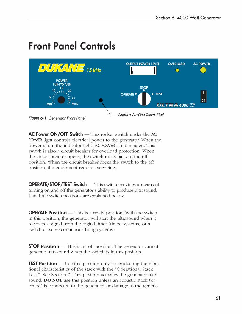
Section 6 4000 Watt Generator
61
Front Panel Controls
AC Power ON/OFF Switch — This rocker switch under the ACPOWER light controls electrical power to the generator. When thepower is on, the indicator light, AC POWER is illuminated. Thisswitch is also a circuit breaker for overload protection. Whenthe circuit breaker opens, the switch rocks back to the offposition. When the circuit breaker rocks the switch to the offposition, the equipment requires servicing.
OPERATE/STOP/TEST Switch — This switch provides a means ofturning on and off the generator’s ability to produce ultrasound.The three switch positions are explained below.
OPERATE Position — This is a ready position. With the switchin this position, the generator will start the ultrasound when itreceives a signal from the digital timer (timed systems) or aswitch closure (continuous firing systems).
STOP Position — This is an off position. The generator cannotgenerate ultrasound when the switch is in this position.
Figure 6-1 Generator Front Panel
OUTPUT POWER LEVEL OVERLOAD AC POWER
POWER
I
OOPERATE
STOP
TEST
IIII
I I
I I I I I I I I I I III
5
1015
20
25
MAXMIN
PUSH TO TURN
15 kHz
4000 AUTOTRAC
Access to AutoTrac Control "Pot"
TEST Position — Use this position only for evaluating the vibra-tional characteristics of the stack with the “Operational StackTest.” See Section 7. This position activates the generator ultra-sound. DO NOT use this position unless an acoustic stack (orprobe) is connected to the generator, or damage to the genera-

Ultra 15 kHz Assembly System User’s Manual
62
OUTPUT POWER LEVEL — The front panel meter indicates thepercentage of power drawn from the generator when the ultra-sound is on. The power drawn varies with each operation. Themeter scale, ranging from 0 to 10, represents 0% power drawn.For instance, 2 represents 20% power drawn, and 10 represents100% power drawn. If the meter reading is in the red portion ofthe scale, beyond 100%, a power overload exists, and the redOVERLOAD light will be lit. Turn the system off. Then, retest thestack using the “Operational Stack Test” in Section 7.
Front Panel Controls, continued
Red OVERLOAD Light — The red OVERLOAD light is lit to indicatea mismatch between the ultrasound signal and the vibrationalcharacteristics of the stack that the generator is driving. It alsolights when too much power is drawn from the generator, andthe meter reading is in the red. At either time, damage to thegenerator may occur. When the OVERLOAD light glows or flick-ers, stop operation, and retest the stack using the “OperationalStack Test”.
POWER Control Knob — This control provides for fine adjust-ment of the stack amplitude. To achieve optimum efficiencyfrom this generator, set this control to as high a setting as pos-sible. Use an exchange of boosters, whenever possible, to varythe amplitude so that this control may remain at a high setting.
Auto-Trac Range Control Potentiometer — A small plug betweenthe POWER knob and the O/S/T selector switch conceals theRange Control “Pot”. Section 7 of the User’s Manual, explainshow this potentiometer may need adjustment in the process ofmatching characteristics of an acoustic stack to the generatoroutput.
tor may result. The O/S/T switch is spring loaded to returnfrom this position to the STOP position automatically whenreleased. Therefore, the switch must be manually held in theTEST position.

Section 6 4000 Watt Generator
63
Rear Panel
Figure 6-2 Generator Rear Panel
Power Cord — All electrical power for the generator is obtainedthrough the generator power cord. The plug on the Ultra 4000generator fits a 3-wire, 2 pole, grounded, 240 VAC, 50/60 Hz,30A single phase outlet. The receptacle is a locking type NEMAL6-30R.
J1 U/S Output — This receptacle connects to the Ultra-Com viaa coaxial ultrasound cable. Through this cable the generatordelivers the 15 kHz ultrasound (U/S) signal to the Ultra-Com.
DO NOT run the generator unless the U/S Outputcable is connected to the Ultra-Com unit, or dam-age to the generator may occur.
In 15 kHz probe systems this cable is an integral part of the probe.Through this cable the generator delivers the 15 kHz ultrasound(U/S) signal to the probe. DO NOT run the generator unless thiscable is connected to the 15 kHz probe or damage to the generatormay occur.
J20 OPERATIONAL CONTROL — The J20 receptacle is only usedin continuous firing systems. The switch closure that starts and
240 VAC50/60 HZ
30A
J1
OPERATIONAL CONTROL
J20
J23
U.S. PATENT 4,277,710
U/S OUTPUT
DUKANE CORPST. CHARLES, ILU/S GENERATORMODEL 15A4000MADE IN USA
— WARNING —POWER MUST BEGROUNDED AT
OUTLET
DISCONNECTPOWERCORD
BEFOREREMOVING
COVER
STATUSRELAY
CAUTION

Ultra 15 kHz Assembly System User’s Manual
64
Space Requirements
Allow 6 inches (153 mm) of space on either side of the genera-tor for air circulation. Allow 5 inches (127 mm) of space to therear for cable connections.
See Dimensions to calculate space needed for base placement.
Generator Dimensions – inches (mm)
Height: 5.50 (140)
Width: 19.00 (483)
Depth: 20.50 (521)
WeightGenerator: 50 lb (22.7 kg)
Rear Panel, continued
stops the ultrasound is connected to this receptacle in thosesystems.
J23 STATUS RELAY — The J23 receptacle is connected to thestatus relay output circuit board mounted inside the generator. Itprovides a SPDT relay contact output on the rear panel. Thisoutput is useful when a floating (non-grounded) mechanicalswitch is needed. The user must provide a load to be switchedand the power source for the load. The power source can beAC or DC within the voltage switching capabilities of the inter-nal relay. The load current must also be within the relay switch-ing capacity.
Ground — This terminal provides a location for connecting thegenerator to earth ground as a backup to the ground connectionat the generator power cord. Connect this terminal to earthground via a customer-provided ground strap prior to operatingthe equipment.
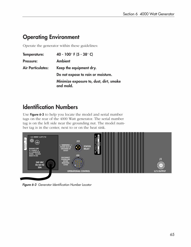
Section 6 4000 Watt Generator
65
Operating EnvironmentOperate the generator within these guidelines:
Temperature: 40 - 100° F (5 - 38° C)
Pressure: Ambient
Air Particulates: Keep the equipment dry.
Do not expose to rain or moisture.
Minimize exposure to, dust, dirt, smokeand mold.
Identification NumbersUse Figure 6-3 to help you locate the model and serial numbertags on the rear of the 4000 Watt generator. The serial numbertag is on the left side near the grounding nut. The model num-ber tag is in the center, next to or on the heat sink.
240 VAC50/60 HZ
30A
J1
OPERATIONAL CONTROL
J20
J23
U.S. PATENT 4,277,710
U/S OUTPUT
DUKANE CORPST. CHARLES, ILU/S GENERATORMODEL 15A4000MADE IN USA
— WARNING —POWER MUST BEGROUNDED AT
OUTLET
DISCONNECTPOWERCORD
BEFOREREMOVING
COVER
STATUSRELAY
SE
RIA
L N
UM
BE
R
US
12
34
56
MO
DE
L
90000 15A4000 123456
DU
KN
E C
OR
PO
RA
TIO
NS
T. C
HA
RL
ES
, ILL
INO
IS U
SA
Figure 6-3 Generator Identification Number Locator

Ultra 15 kHz Assembly System User’s Manual
66
This page intentionally left blank

Dukane Corporation
SECTION 7
System Test
• This section explains how to test the stackbefore the press is put into full production.

Dukane Corporation
This page intentionally left blank

Section 7 System Test
67
OverviewTo operate a Dukane ultrasonic assembly system efficiently, theultrasound signal from the generator must match the frequencyand phase characteristics (vibrational characteristics) of the acous-tic stack it drives. Each stack has unique vibrational characteris-tics depending on the combination of its components. In addi-tion, the characteristics of a particular stack may vary slightlyfrom cycle to cycle because of temperature and loading factors.
The generator’s Auto-Trac feature in combination with Dukane’spatented Phase Lock Loop-Pulse Width Modulation circuitryenables a match between the generator’s signal and the charac-teristics of a particular stack.
The Auto-Trac feature automatically adjusts the ultrasound sig-nal to match the stack’s vibrational characteristics. The momentthe ultrasound turns on during each operating sequence, theAuto-Trac monitors stack motion on a cycle by cycle basis ad-justing the ultrasound signal to an optimal level.
Because the Auto-Trac continuously monitors each operatingsequence, it compensates for vibrational changes that occurduring repeated operations due to heating of the stack compo-nents. It also compensates for aging of the piezoelectric crystalsin the transducer and for horn wear.
The Auto-Trac feature excels in environments hostile to reliableoperation such as high stress, continuous duty applications, orhigh duty cycles in bursts. With this ability to automatically deter-mine the optimal setting for a stack during each operation, theAuto-Trac feature permits the use of one generator with multiple,sequence-fired stacks. In such a situation, the Auto-Trac compen-sates for the unique, vibrational characteristics of each stack dueto differences in aging, loading, temperature, and to the manydifferences in horn configurations.
Auto-Trac Tuning

Ultra 15 kHz Assembly System User’s Manual
68
Operational Stack TestBefore beginning to operate the system for a “full production run”,verify that the stack’s vibrational characteristics fall within the Auto-Trac’s range. To do this, complete the Pre-test Checklist and theAcoustic Stack Test explained below.
NOTE
All Dukane stack components are manufactured to specificationswithin the generator’s Auto-Trac range. A non-Dukane horn, animproperly assembled stack, or a stack component that is worn ordamaged can produce vibrational characteristics outside thesespecifications.
Pre-test Checklist1. Make sure that the correct booster and horn, specified for
the application, are installed in the thruster.
2. Check the press, Ultra-Com, and generator for proper ground-ing.
3. Check the ultrasound cable connections, on the generator,Ultra-Com, and thruster for proper seating and security.
4. Verify that the horn is not under load (in contact with afixture or part).
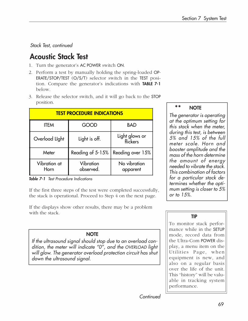
Section 7 System Test
69
Stack Test, continued
If the first three steps of the test were completed successfully,the stack is operational. Proceed to Step 4 on the next page.
If the displays show other results, there may be a problemwith the stack.
Continued
TIPTo monitor stack perfor-mance while in the SETUPmode, record data fromthe Ultra-Com POWER dis-play, a menu item on theUti l i t ies Page, whenequipment is new, andalso on a regular basisover the life of the unit.This “history” will be valu-able in tracking systemperformance.
Acoustic Stack Test1. Turn the generator’s AC POWER switch ON.
2. Perform a test by manually holding the spring-loaded OP-ERATE/STOP/TEST (O/S/T) selector switch in the TEST posi-tion. Compare the generator’s indications with TABLE 7-1below.
3. Release the selector switch, and it will go back to the STOPposition.
**
Table 7-1 Test Procedure Indications
NOTEThe generator is operatingat the optimum setting forthis stack when the meter,during this test, is between5% and 15% of the fullmeter scale. Horn andbooster amplitude and themass of the horn determinethe amount of energyneeded to vibrate the stack.This combination of factorsfor a particular stack de-termines whether the opti-mum setting is closer to 5%or to 15%.
If the ultrasound signal should stop due to an overload con-dition, the meter will indicate “0”, and the OVERLOAD lightwill glow. The generator overload protection circuit has shutdown the ultrasound signal.
NOTE
TEST PROCEDURE INDICATIONS
ITEM GOOD BAD
Overload LIght Light is off. Light glows orflickers
Meter Reading of 5-15% Reading over 15%
Vibration atHorn
Vibrationobserved.
No vibrationapparent

Ultra 15 kHz Assembly System User’s Manual
70
Under normal conditions, the 15 kHz ultrasound signal can beeasily heard. The paper test provides a visual confirmation ofthe active ultrasound signal.
NOTE
4. To see if the ultrasound signal is being transmitted to the horn:First, fold a small scrap of paper once (ordinary 20# copy paperwill work for this purpose), and place it on the press base orfixture about an inch from the tip of the horn.Turn the selector switch to TEST.
The paper should “bend” slightly away from the horn as shown inFigure 7-1. If no movement is seen, there may be a problem withthe stack. Release the selector switch so that it returns to the STOPposition.
Acceptable Results
If all the indicators from Steps 1-4 are acceptable, the stack iswithin the Auto-Trac range. Proceed to Running Sample Partsand Making Adjustments.
Unacceptable Results
If one or more of the indicators are unacceptable, go to Step 5.
5. Turn the generator and Ultra-Com off. Check the stack forcorrect assembly, damaged components, or dirty matingsurfaces. Make any repairs or adjustments to the stack. Re-check the ultrasound cable for proper connections. RepeatSteps 1 through 4. If the test still fails, go to Step 6.
6. Turn the generator off. Remove the stack from the thruster,and remove the horn from the stack. Resinstall only the trans-ducer-booster assembly into the thruster. Repeat Steps 1-4 ofthe previous page.
Operational Stack Test, continued
Figure 7-1 Paper Test

Section 7 System Test
71
Stack Test, continued
Good Indications with Horn Removed
If good indications are given with the horn removed, it meansthat the horn is outside the specifications required to oper-ate within the Auto Trac preset range.
Reassemble the horn to the stack, and go to the “RangeAdjustment of the Auto-Trac Feature” that follows.
Bad Indications with Horn Removed
If bad indications are present with the horn removed, checkthe booster and the transducer for the following:
• any visible damage,• loose or cracked stud, or• pitted or dirty mating surfaces.
Make any necessary repairs or adjustments.
Go to Step 7.
7. Repeat Steps 1-6. If the bad indicators disappear, reattach thehorn to the stack, and repeat Steps 2-4.
• If any bad indications are still present, do not run thisstack. Call Dukane Service for assistance.
Range Adjustment of the Auto-Trac Feature
NOTE
Do not adjust the Auto-Trac range unless the precedingStack Test procedure directs you to do so. New Dukanehorns are designed to operate with “home” for the Auto-Trac range control being set at the three o’clock/nineo’clock position. If you adjust this control to operate anolder or non-Dukane horn, return it to the home positionbefore trying to run another horn.
The goal of this adjustment is to run the horn without any ofthe bad indicators shown in Table 7-1.
Continued
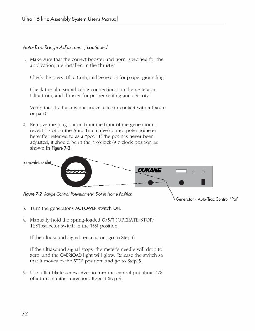
Ultra 15 kHz Assembly System User’s Manual
72
1. Make sure that the correct booster and horn, specified for theapplication, are installed in the thruster.
Check the press, Ultra-Com, and generator for proper grounding.
Check the ultrasound cable connections, on the generator,Ultra-Com, and thruster for proper seating and security.
Verify that the horn is not under load (in contact with a fixtureor part).
2. Remove the plug button from the front of the generator toreveal a slot on the Auto-Trac range control potentiometerhereafter referred to as a “pot.” If the pot has never beenadjusted, it should be in the 3 o’clock/9 o’clock position asshown in Figure 7-2.
Figure 7-2 Range Control Potentiometer Slot in Home Position
3. Turn the generator’s AC POWER switch ON.
4. Manually hold the spring-loaded O/S/T (OPERATE/STOP/TEST)selector switch in the TEST position.
If the ultrasound signal remains on, go to Step 6.
If the ultrasound signal stops, the meter’s needle will drop tozero, and the OVERLOAD light will glow. Release the switch sothat it moves to the STOP position, and go to Step 5.
5. Use a flat blade screwdriver to turn the control pot about 1/8of a turn in either direction. Repeat Step 4.
Auto-Trac Range Adjustment , continued
Screwdriver slot123456789012345123456789012345123456789012345
Generator - Auto-Trac Control “Pot”
Section 7 System Test
73
Auto-Trac Range Adjustment , continued
NOTEEach time you return to Step 5, turn the pot another 1/8 turnin the same direction it was turned at first. (The pot has amechanical stop just short of 180 degrees from the home po-sition in both directions.) If the stop is met in one directionand the ultrasound signal will not stay on, return the pot to thehome position. Then repeat Steps 4 and 5 turning the pot theother way.
If the signal will not stay on after followng the above steps,do not run the horn until it is evaluated and the situa-tion resolved. Discuss the details with Dukane personnel.The horn may need to be sent in for evaluation.Move the slot on the control pot to the home position, andreplace the plug button in the generator front panel.
6. While holding the O/S/T switch in the TEST position, slowlyturn the control pot in one direction, and then the otherdirection. Find a position where all of the bad indicatorsdisappear. If the ultrasound signal shuts off, release the O/S/T switch. Return the pot to a position where the signalstayed on. Repeat this step while turning the pot in theoppostite direction. The pot has a mechanical stop just lessthan 180 degrees from the home position (either direction).
If the signal will not stay on after completing the above steps,do not run the horn until it is evaluated. Discuss the de-tails with Dukane personnel.
Move the slot on the control pot to the home position, andreplace the plug button in the generator front panel.
If there is a position where the bad indicators disappear, tryturning the pot a bit more to find the position with the lowestpossible meter reading. Release the O/S/T switch to the STOPposition when this is done, and go to Step 7.
7. Record the position of the range control pot to operatethis particular stack with your Ultra-Com/generator. Whenusing this stack in the future, adjust the range controlbefore completing the Operational Stack Test. Put the plugbutton back into the generator front panel, and rememberto leave the control pot in the 3 and 9 home positionbefore using another horn.
Ultra 15 kHz Assembly System User’s Manual
74
Cycling the System1. Check that you have correctly performed the following:
a. Installed the stack in the thruster and securely closed thestack access cover.
b. Secured the fixture in place.c. Completed the Operational Stack Test.
2. Select the Ultra-Com OPERATE mode with the Front Panel modeselect keyswitch. Also set the OPERATE/STOP/TEST switch onthe generator to the OPERATE position.
3. Verify that all controls, on the press/thruster and the Ultra-Com, are set as required for this operation.
4. Place a part in the fixture.
5. Cycle the system. If using the dual push button activationswitches to start the system cycle, press them both simulta-neously, and hold them until the ultrasound signal starts. Re-leasing the activation switches before the ultrasound startswill abort the cycle.

Section 7 System Test
75
Running Sample Parts
If the samples are not acceptable, make adjustments as neces-sary. If further assistance is needed, contact Dukane. Section 11lists the Dukane contacts.
When monitoring an application, two elements that should al-ways be observed are Power Draw and Assembled Part Quality.If sample parts are made using an acceptable power draw, andif they meet quality standards and any other application-depen-dent criteria, then a full production run can be initiated.
Power DrawBefore cycling the system, get in position to watch the Ultra-ComFront Panel display where POWER can be shown. From the Ultra-Com SETUP menu choose UTILITIES, then POWER UTILITIES, then POWER.
How much power is being drawn from the generator?
Discontinue operation if the meter needle moves into the red areaor if the OVERLOAD light glows at all. The generator will no longerproduce an ultrasound signal while in an overload condition.
If Overloading OccursIf overloading occurs, discontinue the operation.
Perform the Operational Stack Test (described above)or see Section 9, Troubleshooting for more information.
Assembled Part QualityCheck assembled part quality for the following:
a. Strength of the joint or seam, andb. Appearance: Does the assembled part meet the quality
standards for appearance?
Making Adjustments
CAUTIONRepeated operations that draw too muchpower from the generator can damage systemequipment.
TIPThe most importantelements to monitorare always dependenton the application.
For instance, Time,Distance, and En-ergy can be criticalelements to watch.
For more informa-tion, refer to Table10-1 which gives ex-amples of weldcharacteristics andtheir relation to sys-tem components.

Ultra 15 kHz Assembly System User’s Manual
76
This page intentionally left blank
Dukane Corporation
SECTION 8
System Operation
• This section provides a start-up checklist,procedures for starting and stopping, andsuggestions when considering systemchanges.

Dukane Corporation
This page intentionally left blank

Section 8 System Operation
77
Overview
1. CablesAre all cables properly connected with retaining ringsscrewed tightly in place?
2. GroundingIs the customer-supplied “source ground” properly con-nected to the Ultra-Com, generator, and press/thruster?
3. Air FilterIs the air filter at the rear of the thruster clean ?
4. Air Lockout ValveIs the valve unlocked and in the “open” position?
5. Acoustic StackIs the stack properly assembled and installed in thethruster, and is the stack access cover securely bolted?
6. Horn, Booster, FixtureAre the horn, booster and fixture correct for the applica-tion to be performed? Check all three items for cracks,chips and alignment.
7. Mechanical StopWill the mechanical stop prevent the horn from hitting thefixture (when a part is not in the fixture)?
8. Ultra-Com and Generator
When power to the Ultra-Com and generator was turnedon, did the units complete start-up sequences successfully?
Daily Start-up Checklist
When system installation is complete, and sample parts havebeen successfully assembled, the system is ready for anextended run.This section of the User’s Manual provides a checklist to usebefore start-up, and it gives some basic operating instructionson starting and stopping the system.
Answer each question with a “Yes”, before starting:= YES
(pages 15-25)
(pages 8-10)
For units equipped with the press support package.
(page 36)
(page 34)
(Ultra-Com: See User’s Manual P/N 403-393C; Generator: See Section 6 of this manual.)
(pages 45-53)

Ultra 15 kHz Assembly System User’s Manual
78
Start-upAfter completing the Daily Start-up Checklist, you are ready forsystem start-up. See the previous page for the Checklist.
1. Turn air power on.
2. Perform the Operational Stack Test as outlined in Section 6 ofthis User’s Manual.
3. Verify that all controls, on the press/thruster, on the Ultra-Com and on the generator are set as required for your par-ticular application.
4. Place a part in the fixture.
5. Start the system manually or automatically.
Manual Start
If using the dual push button activation switches to start thesystem cycle, press them both at the same time, and hold themuntil the ultrasound signal starts.
Releasing the buttons before the ultrasound starts causes an errorin the start-up sequence, and the cycle will stop.
Automatic StartThe system may be activated using customer-supplied controlsthat are linked through the Ultra-Com to start the cycle automati-cally based on a predetermined sequence of events.
6. After the system has started, monitor the Ultra-Com and thegenerator output for overload indications.
Start-up, continued
NOTE

Section 8 System Operation
79
PUSH FOR EMERGENCY OFFSwitch (Red)
Right Activation Switch
Base Plate
LeftActivationSwitch
Press Status (LED) Display (Black)
(Black)
Stopping the System
Normal Conditions
Emergency Conditions
The press stops when the programmed cycle ends.A programmed cycle can have one step or multiple steps.
Manual SystemPress the red PUSH FOREMERGENCY OFFswitch (palm but-ton) on the pressbase plate.
See Figure 8-1.
Four things hap-pen when theswitch is pressed:
• the ultrasoundsignal is turnedoff immediately,
• electrical power to the press is removed,• a firmware emergency stop sequence is begun, and• the word ABORT appears in the Press Status Display.
Automated SystemAn automated system has external controls supplied by thecustomer that will stop the cycle automatically. Those controlsare connected to the rear of the Ultra-Com at the AUTO INPUTconnector, J9.
As long as the PUSH FOR EMERGENCY OFF switch is pushed in,these conditions are active.
Twist and pull the PUSH FOR EMERGENCY OFF button to allowthe press to reactivate.
Figure 8-1 Press Base Switches
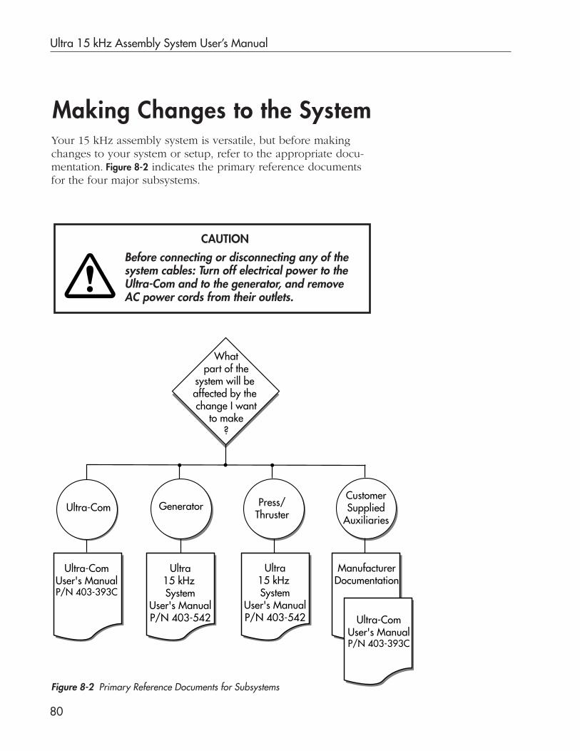
Ultra 15 kHz Assembly System User’s Manual
80
Making Changes to the System
Before connecting or disconnecting any of thesystem cables: Turn off electrical power to theUltra-Com and to the generator, and removeAC power cords from their outlets.
CAUTION
Your 15 kHz assembly system is versatile, but before makingchanges to your system or setup, refer to the appropriate docu-mentation. Figure 8-2 indicates the primary reference documentsfor the four major subsystems.
Figure 8-2 Primary Reference Documents for Subsystems
Whatpart of the
system will be affected by the change I want
to make?
Ultra-Com Press/Thruster
Ultra-ComUser's ManualP/N 403-393C
Ultra15 kHz System
User's ManualP/N 403-542
Ultra15 kHz System
User's ManualP/N 403-542
ManufacturerDocumentation
CustomerSupplied
AuxiliariesGenerator
Ultra-ComUser's ManualP/N 403-393C

Dukane Corporation
SECTION 9
Maintenance
• In this section maintenance for the majorsystem components is outlined.

Dukane Corporation
This page intentionally left blank
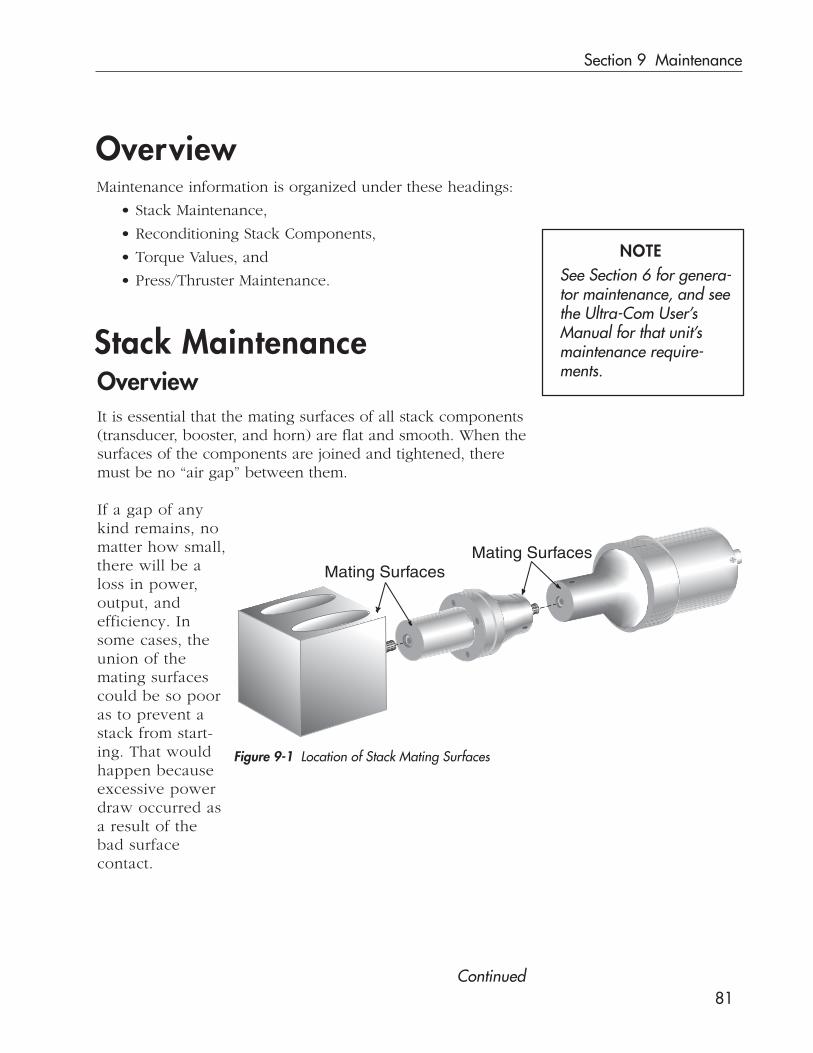
Section 9 Maintenance
81
OverviewMaintenance information is organized under these headings:
• Stack Maintenance,
• Reconditioning Stack Components,
• Torque Values, and
• Press/Thruster Maintenance.
Stack MaintenanceOverviewIt is essential that the mating surfaces of all stack components(transducer, booster, and horn) are flat and smooth. When thesurfaces of the components are joined and tightened, theremust be no “air gap” between them.
If a gap of anykind remains, nomatter how small,there will be aloss in power,output, andefficiency. Insome cases, theunion of themating surfacescould be so pooras to prevent astack from start-ing. That wouldhappen becauseexcessive powerdraw occurred asa result of thebad surfacecontact.
Continued
Figure 9-1 Location of Stack Mating Surfaces
Mating SurfacesMating Surfaces
NOTESee Section 6 for genera-tor maintenance, and seethe Ultra-Com User’sManual for that unit’smaintenance require-ments.

Ultra 15 kHz Assembly System User’s Manual
82
Inspecting the StackLook at the mating surfaces to see where the shiny, burnishedareas are. These areas show where the surfaces have been incontact, and indicate that the surfaces themselves are eitherflat or uneven.
Surfaces with Even ContactA flat surface has made even contact, and will be uniformlyburnished across its entire contact area.Figure 9-2 illustrates that type of contact.
Surfaces with Uneven Contact
A surface that is not completely flat makes uneven contact,and will be burnished in only part of its contact area.Figure 9-3 shows what a surface would look like if only theinner area had been making contact, because that is whereburnishing has taken place. The outer area has no marks atall, indicating there has been no contact there.
Figure 9-2 Burnished Area IndicatesFlat Mating Surfaces
Figure 9-3 Burnished Area IndicatesUneven Mating Surfaces
As shown in Figure 9-3 the burnished area appears only aroundthe mounting stud area, and not at the edges. This is evidenceof “crowning” illustrated in Figure 9-4.
To get some idea of the extent of the problem, put a straightedge along the surface of the stack element being inspected.Because the stack element as shown in Figure 9-4 is crowned atthe center, there are gaps along the outer edge of the element.
Crowning
An element’s surface may also be depressed in the mountingstud area. See Figure 9-5. This element would make contactonly at the outer edge.
Again, a straight edge placed along the mating surface of thestack element gives an idea of the extent of the problem. Agap visible beneath the straight edge near the center of theelement shows how deep the depression is.
Center DepressionFigure 9-4 Example of Crowning
Figure 9-5 Center Depression
}
BurnishedArea
Hole forMountingStud
}
BurnishedArea
StraightEdge
Crown
Gap
StraightEdge
Gap

Section 9 Maintenance
83
Surfaces with Uneven Contact, continued
Corrosion
Corrosion is another factor to consider in determining overallsystem performance. In time, corrosion can build up on stackmating surfaces, and contribute to a loss in performance. Evi-dence of corrosion includes discolored mating surfaces or sur-faces that are encrusted with hard deposits.
To extend equipment life and to keep performance levels high,minimize the system’s exposure to any corrosive source.
NOTE
Ultra 15 kHz Assembly System User’s Manual
84
Reconditioning Stack ComponentsOverviewStack components need reconditioning when mating surfacesbecome uneven or corroded. These conditions cause poorcontact between the mating surfaces. This wastes power,makes tuning of the acoustic stack difficult, can cause heatdamage to the transducer, and can contribute to a highersystem noise level.
NOTE
Before deciding to recondition mating surfaces on yourown, consider calling Dukane Corporation’s ToolingSupport to discuss the situation. This is especially true if themating surfaces are uneven because machining of thecomponents may be required. Factory personnel can offertheir skills and experience for your situation.See Section 11 for a list of Dukance contacts.
1. Disassemble the acoustic stack, and wipe all the matingsurfaces with a clean cloth or paper towel.
2. Examine all of the surfaces. If any is corroded (discoloredor coated with hard deposits), it should be reconditioned.
Follow the steps below to manually resurface the stack compo-nents’ mating surfaces.
Reconditioning the Mating Surfaces
Instruction to machine the stack components is beyond thescope of this User’s Manual. Please call Dukane’s ToolingSupport team for machining information. See Section 11 for alist of Dukane contacts.
Machining
Manual Resurfacing
Continued

Section 9 Maintenance
85
Resurfacing Components, continued
3. If the surfaces appear as if they are in good condition, goto Step 11.
4. If necessary, remove the mounting studs.
5. Tape a clean sheet of #400 grit (or finer) emery cloth to aclean, smooth, flat surface (such as a piece of plate glass)so the grit side is up.
6. Hold the stack component with one hand as shown inFigure 9-6. This view shows the thumb covering one of thethree spanner wrench holes.Without applying any downward pressure, carefully strokethe part IN ONE DIRECTION across the emery cloth. (Thecomponent’s weight alone will be enough as the part ismoved.) Complete a second stroke across the cloth justlike the first one.
Use extreme care to keep the part level whenmoving it across the emery cloth. Do not tilt it.An uneven mating surface could leave the
welding system inoperative.
7. Keep the element’s surface flat against the emery cloth,and turn it 120° (one-third of a complete rotation) so thethumb covers the next spanner wrench hole. Again, movethe part twice across the emery cloth as outlined in Step 6.
8. Give the part a final one-third turn, and repeat the twostrokes described in Step 6.
Figure 9-6 Manual Resurfacing
CAUTION
CAUTION
It is important to perform only 2 strokes eachtime the component is rotated 120°. Perform-ing more or fewer strokes affects whether the
surface remains flat. If the surface loses its perpendicularityin relationship to the component’s centering axis, the weld-ing system may become inoperative.

Ultra 15 kHz Assembly System User’s Manual
86
Resurfacing Components, continued
10. Mounting studs need to be reinserted, but before that is doneget proper thread engagement by:
• inspecting and cleaning the stud,• cleaning the threaded hole with a cloth, and• threading the stud into the hole, and tightening it to the
torque specifications shown in Table 9-1 on the next page.
11. Reassemble the stack and install it using the procedureshown in Section 5.
12. Complete the Operational Stack Test shown in Section 7.
9. Reexamine the mating surfaces, and repeat Steps 6 – 8 untilthe corrosion has been removed. Typically this takes no morethan three complete rotations of the component.
NOTEThreads may deform if the studs are overtightened. Removinga stud that has been overtightened could damage the threadsin the horn.If this should happen, retap the horn threads, and replace thestud with a new one.

Section 9 Maintenance
87
Torque Values
OverviewApply torque values from the three categories listed belowwhen reassembling stack components:
• Stack assembly values (below)• Booster and horn stud values (Table 9–1)• Tip torque values (Table 9–2)
A 15 kHz acoustic stack consists of a transducer, a booster,and a horn. Use the following torque value when assemblingthe stack.
• 250 inch-pounds• 20.8 foot-pounds• 28.2 Newton-meters.
Stack Assembly Torque Value
Do not overtighten stack components.Overtightening may cause studs toloosen, causing the generator to go intoan OVERLOAD condition.
CAUTION
Booster and Horn Stud Torque Values
Table 9-1 Booster and Horn Stud Torque
Use the torque values shown in Table 9-1 when installing studsinto either a booster or horn to be used in a 15 kHz stack.
Stud ThreadSize
Torque
Inch-pounds Foot-pounds Newton-meters
3/4 - 16 200 16.7 22.5
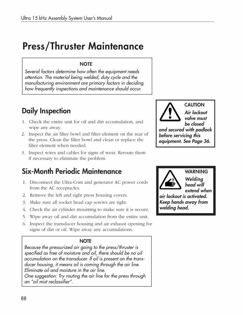
Ultra 15 kHz Assembly System User’s Manual
88
Press/Thruster Maintenance
Six-Month Periodic Maintenance1. Disconnect the Ultra-Com and generator AC power cords
from the AC receptacles.
2. Remove the left and right press housing covers.
3. Make sure all socket head cap screws are tight.
4. Check the air cylinder mounting to make sure it is secure.
5. Wipe away oil and dirt accumulation from the entire unit.
6. Inspect the transducer housing and air exhaust opening forsigns of dirt or oil. Wipe away any accumulations.
Daily Inspection
2. Inspect the air filter bowl and filter element on the rear ofthe press. Clean the filter bowl and clean or replace thefilter element when needed.
3. Inspect wires and cables for signs of wear. Reroute themif necessary to eliminate the problem.
Several factors determine how often the equipment needsattention. The material being welded, duty cycle and themanufacturing environment are primary factors in decidinghow frequently inspections and maintenance should occur.
NOTE
1. Check the entire unit for oil and dirt accumulation, andwipe any away.
CAUTION
Air lockoutvalve mustbe closed
and secured with padlockbefore servicing thisequipment. See Page 36.
WARNINGWeldinghead willextend when
air lockout is activated.Keep hands away fromwelding head.
Because the pressurized air going to the press/thruster isspecified as free of moisture and oil, there should be no oilaccumulation on the transducer. If oil is present on the trans-ducer housing, it means oil is coming through the air line.Eliminate oil and moisture in the air line.One suggestion: Try routing the air line for the press throughan “oil mist reclassifier”.
NOTE
Section 9 Maintenance
89Continued
7. Check the thruster slide for smooth downward operation.Wipe away any accumulated grease, but do not apply anysolvents. If movement is not smooth, apply a small amount of30 weight oil to a rag, and wipe the two slide rails with it.
8. Ensure that all wires and cable connections for the entiresystem are secure. If cables or wires show wear, reroute themto eliminate the problem.
9. Replace the left and right press housing covers.
10. Reconnect the Ultra-Com and generator AC power cords totheir respective AC receptacles.
Press/Thruster Maintenance, continued

Ultra 15 kHz Assembly System User’s Manual
90
This page intentionally left blank

Dukane Corporation
Troubleshooting
SECTION 10

Dukane Corporation
This page intentionally left blank
Section 10 Troubleshooting
91
Overview
This first part of this troubleshooting section provides infor-mation to help identify causes and to recommend solutionsfor problems you may have during:
• Welding,
• Inserting,
• Staking, or
• Continuous Welding.
The Process Troubleshooting material, on Pages 93-107, hasthese three elements:
• Problem,
• Probable Cause, and
• Solution.
Beginning on Page 108, the second part of this section givesinformation focused on equipment troubleshooting.
Continued
Equipment Troubleshooting
Process Troubleshooting

Ultra 15 kHz Assembly System User’s Manual
92
Troubleshooting Overview, continued
Dukane Corporation’s Ultra Systems support those primary weldcharacteristics for which they have been configured. Solutions of-fered here may or may not apply to your particular welding system.
Primary weld characteristics such as Time, Distance, AbsoluteDistance, Energy, and Peak Power are used to control the weld-ing process. Each characteristic needs certain system componentsto support it. Table 10-1 shows each characteristic with correspond-ing equipment requirements.
NOTE
The End of Weld limit switch is used to end the ultrasound signalduring a weld cycle based on the press head’s stroke position. Ingeneral, the switch is not used when a system has an Ultra-Comwith distance measurement function and a press/thrusterequipped with a linear encoder.
Process Troubleshooting
Table 10-1 Equipment Requirements for Primary Weld Characteristics
Primary Weld Characteristics
Characteristic
Time
Distance
Absolute Distance
Energy, Peak Power
Equiment Requirements
Ultra-Com with a time function.
Ultra-Com with a distance measurement function(distance module) and a press or thruster equip-ped with a linear encoder.
Ultra-Com with a distance measurement function(distance module) and a press or thruster equip-ped with a linear encoder, or a press/thrusterwith and End of Weld limit switch installed.
Ultra-Com with an energy measurement function(energy/power module).

Section 10 Troubleshooting
93
Welding__________________________________________________________________________________________________
Problem
Flash occurs. (See also Uneven welding occurs, on Page 96.)
Probable Cause Solution
Energy director is too large. Reduce the size of the energydirector.Reduce the weld time/primary weldcharacteristic.Reduce the gauge pressure.Use an interrupted energy director.
Shear interference is too great. Reduce the amount of interference.
Weld time is too long. Reduce the weld time.
Nonuniform joint dimensions. Re-dimension the joint.Redesign the joint to be a shear joint ora tongue-in-groove joint.Check the processing conditions.
Part fit or tolerances. Loosen the part fit.Loosen the part tolerances.
_________________________________________________________________________________________________
Problem
Welded assembly is misaligned.
Probable Cause Solution
Parts are not self-aligning. Design a way to align parts as they go intothe tooling (fixturing).Add a means of alignment (e.g., pinsand sockets) to the mating part halves.
Improper support in the fixture. Redesign the fixture for proper support.
Wall flexure. Add ribs or gussets to the part.With a resilient fixture, if large sectionsof urethane are deflecting, add a rigidbackup.
Joint design is not properly dimensioned. Re-dimension the parts.
Incorrect part tolerance/poor molding. Tighten the part tolerance.Check the processing conditions.
_________________________________________________________________________________________________

Ultra 15 kHz Assembly System User’s Manual
94
Welding_________________________________________________________________________________________________
Problem
Internal components are being welded together.
Probable Cause Solution
The internal components are made Make the internal components out ofof the same material. another material.
Carefully lubricate the internal parts.Reduce amplitude by changing to a lowergain booster.
_________________________________________________________________________________________________
Problem
Diaphragmming* occurs.
Probable Cause Solution
Excessive amplitude. Reduce the amplitude.Dampen the welding area to absorb theamplitude.
Excessive exposure to ultrasound. Reduce the weld time by increasing theamplitude and/or the gauge pressure.
Improper gate location/design/thin Check gate placement.wall sections. Change the shape of the gate.
Add stiffening ribs to the part.Increase the thickness of the material onthe underside of the gate area.
The type of horn and/or its placement. Check for the proper horn/part fit.Change the horn.
_________________________________________________________________________________________________
Problem
Overwelding occurs.
Probable Cause Solution
Too much energy is being transmitted Reduce the gauge pressure.to the part. Reduce the weld time/primary weld
characteristic.Change to a lower gain booster to reduce theamplitude.Reduce downstroke speed.
_________________________________________________________________________________________________
* Diaphragmming occurs when the center of a part vibrates to causestress, cracking, or melting of that part.

Section 10 Troubleshooting
95
Welding________________________________________________________________________________________________
Problem
Internal components were damaged during welding.
Probable Cause Solution
Excessive amplitude. Reduce the amplitude by changing to a lowergain booster.Otherwise dampen the excess amplitude.
Excessive exposure to ultrasound. Reduce the primary weld characteristic.Increase the amplitude by changing to ahigher gain booster.
Too much energy transmitted into Reduce the amplitude.the part. Reduce the gauge pressure.
Reduce the weld time/primary weld charac-teristic.
The components are improperly Make sure internal components are mountedmounted–E.g.: Parts are mounted properly.too close to the joint area. Isolate internal components from the part.
Move the internal components away fromareas of high energy.Use an external device to dampen energylocally.
_________________________________________________________________________________________________
Problem
Melting or fracturing of the part occurs. (outside of the joint area)
Probable Cause Solution
Sharp internal corners/thin sections. Radius all sharp corners.Dampen any damaged area, if possible.
Excessive amplitude. Reduce the amplitude by changing to a lowergain booster.
A long weld time. Decrease the weld time.Increase the amplitude.Increase the gauge pressure.
Inherent stress. Check the molding conditions.Check the part design.Reduce the amplitude.
_________________________________________________________________________________________________

Ultra 15 kHz Assembly System User’s Manual
96
Welding_________________________________________________________________________________________________
Problem
Underwelding occurs.
Probable Cause Solution
Insufficient energy is being transmitted Increase the gauge pressure.to the part. Increase the weld time/primary weld charac-
teristic.Change to a higher gain booster to increasethe amplitude.Use a more powerful assembly system.
Energy is being absorbed into Change the type of fixture being used.the fixture.
________________________________________________________________________________________________
Problem
Uneven welding occurs.
Probable Cause Solution
Warped part(s). Check part dimensions.Check the molding conditions.Use a higher trigger pressure.Use a higher hold pressure.
The energy director varies in height. Redesign the energy director to ensure uni-form height.Use an interrupted energy director.
Horn, fixture and the part are not Make sure the thruster is perpendicular.properly aligned with each other. Check the part dimensions.
Wall flexure is occurring. Add ribs to the part.Modify the fixture to prevent outward flexure.
The knockout pin location is in the Redesign the part so the knockout pinjoint area. is not in the joint area. (Make sure knockout
pins are flush with the surface.)
There is insufficient support in Redesign the fixture to improve thethe fixture. support in critical areas.
Change to a rigid fixture.With a resilient fixture, if large sections ofurethane are deflecting, add a rigid backup.
_________________________________________________________________________________________________
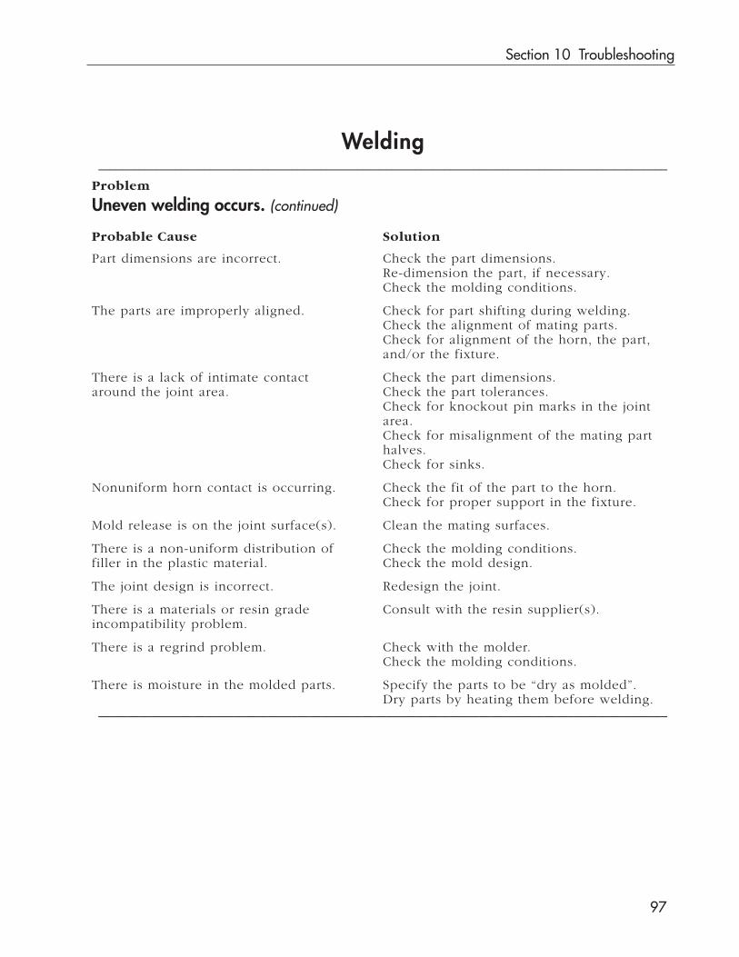
Section 10 Troubleshooting
97
Welding_________________________________________________________________________________________________
Problem
Uneven welding occurs. (continued)
Probable Cause Solution
Part dimensions are incorrect. Check the part dimensions.Re-dimension the part, if necessary.Check the molding conditions.
The parts are improperly aligned. Check for part shifting during welding.Check the alignment of mating parts.Check for alignment of the horn, the part,and/or the fixture.
There is a lack of intimate contact Check the part dimensions.around the joint area. Check the part tolerances.
Check for knockout pin marks in the jointarea.Check for misalignment of the mating parthalves.Check for sinks.
Nonuniform horn contact is occurring. Check the fit of the part to the horn.Check for proper support in the fixture.
Mold release is on the joint surface(s). Clean the mating surfaces.
There is a non-uniform distribution of Check the molding conditions.filler in the plastic material. Check the mold design.
The joint design is incorrect. Redesign the joint.
There is a materials or resin grade Consult with the resin supplier(s).incompatibility problem.
There is a regrind problem. Check with the molder.Check the molding conditions.
There is moisture in the molded parts. Specify the parts to be “dry as molded”.Dry parts by heating them before welding.
_________________________________________________________________________________________________
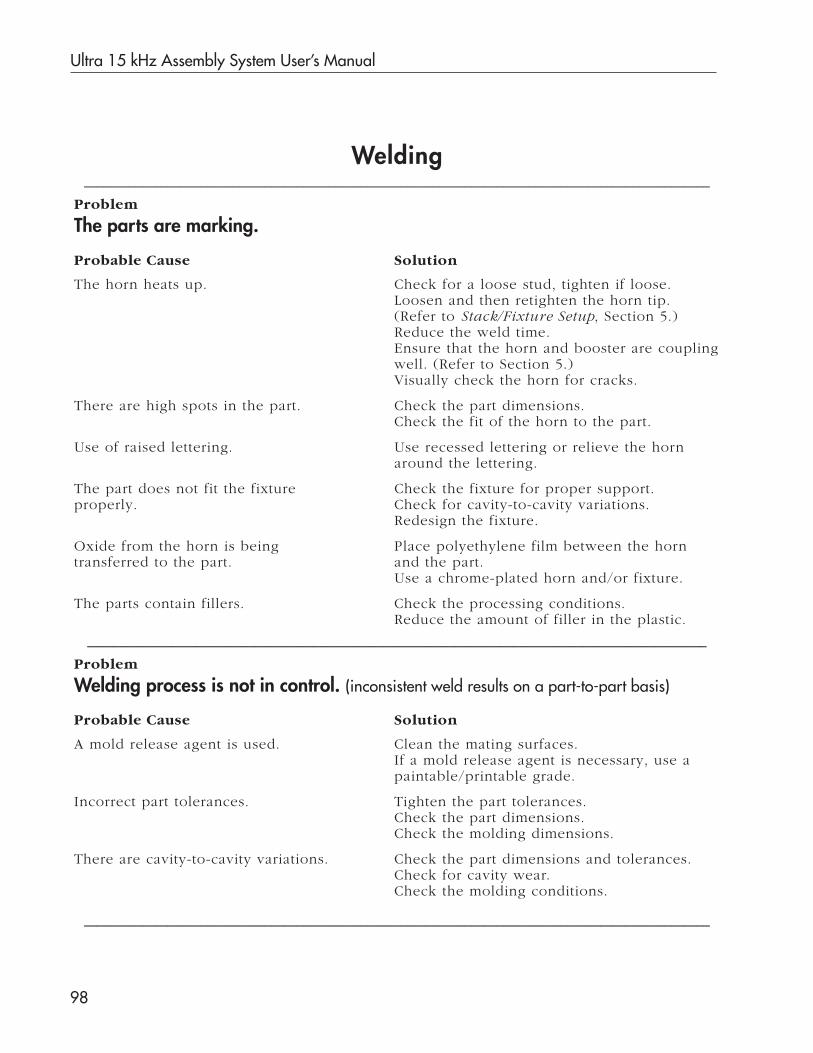
Ultra 15 kHz Assembly System User’s Manual
98
Welding_________________________________________________________________________________________________
Problem
The parts are marking.
Probable Cause Solution
The horn heats up. Check for a loose stud, tighten if loose.Loosen and then retighten the horn tip.(Refer to Stack/Fixture Setup, Section 5.)Reduce the weld time.Ensure that the horn and booster are couplingwell. (Refer to Section 5.)Visually check the horn for cracks.
There are high spots in the part. Check the part dimensions.Check the fit of the horn to the part.
Use of raised lettering. Use recessed lettering or relieve the hornaround the lettering.
The part does not fit the fixture Check the fixture for proper support.properly. Check for cavity-to-cavity variations.
Redesign the fixture.
Oxide from the horn is being Place polyethylene film between the horntransferred to the part. and the part.
Use a chrome-plated horn and/or fixture.
The parts contain fillers. Check the processing conditions.Reduce the amount of filler in the plastic.
________________________________________________________________________________________________
Problem
Welding process is not in control. (inconsistent weld results on a part-to-part basis)
Probable Cause Solution
A mold release agent is used. Clean the mating surfaces.If a mold release agent is necessary, use apaintable/printable grade.
Incorrect part tolerances. Tighten the part tolerances.Check the part dimensions.Check the molding dimensions.
There are cavity-to-cavity variations. Check the part dimensions and tolerances.Check for cavity wear.Check the molding conditions.
_________________________________________________________________________________________________

Section 10 Troubleshooting
99
Welding_________________________________________________________________________________________________
Problem
Welding process is not in control. (inconsistent weld results on a part-to-part basis)(continued)
Probable Cause Solution
Part dimensions vary due to mold Perform a statistical study to see if a pat-cavity variations. tern develops with certain cavity combina-
tions.
The resin contains regrind or degraded Consult with the molder.plastic. Check the molding conditions.
Reduce the percentage of regrind.Improve the quality of the regrind.
Fluctuations in the AC line voltage Upgrade to a generator with linesupplied to the generator. regulation.
Fluctuations in the air line pressure. Upgrade to a system with electronic pressureregulation.Add a surge tank with a check valve to theair line.Raise the compressor output pressure.
The plastic’s filler content is too high. Reduce the percentage of filler in the plastic.Check the processing conditions.Change the type of filler (i.e., from short tolong glass fibers).
The horn doesn’t fit the part correctly. Check the part dimensions.Check for cavity-to-cavity variations.Obtain a new horn.
The weld cycle is too long. Reduce the weld cycle time by increasing theamplitude or pressure.Change the dynamic trigger force.
There is misalignment between Check for alignment between the horn,the horn, part, and/or fixture. part, and fixture.
Check the horn/part fit.Check the part/fixture fit.Level the fixture, where necessary.
Rigid fixture reflects vibratory energy. Dampen the energy by using teflon, neo-prene, cork, or urethane in the nest of thefixture.
_________________________________________________________________________________________________
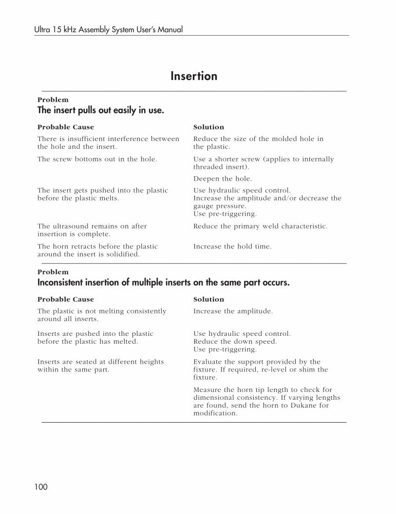
Ultra 15 kHz Assembly System User’s Manual
100
Insertion_________________________________________________________________________________________________
Problem
The insert pulls out easily in use.
Probable Cause Solution
There is insufficient interference between Reduce the size of the molded hole inthe hole and the insert. the plastic.
The screw bottoms out in the hole. Use a shorter screw (applies to internallythreaded insert).
Deepen the hole.
The insert gets pushed into the plastic Use hydraulic speed control.before the plastic melts. Increase the amplitude and/or decrease the
gauge pressure.Use pre-triggering.
The ultrasound remains on after Reduce the primary weld characteristic.insertion is complete.
The horn retracts before the plastic Increase the hold time.around the insert is solidified.
_________________________________________________________________________________________________
Problem
Inconsistent insertion of multiple inserts on the same part occurs.
Probable Cause Solution
The plastic is not melting consistently Increase the amplitude.around all inserts.
Inserts are pushed into the plastic Use hydraulic speed control.before the plastic has melted. Reduce the down speed.
Use pre-triggering.
Inserts are seated at different heights Evaluate the support provided by thewithin the same part. fixture. If required, re-level or shim the
fixture.
Measure the horn tip length to check fordimensional consistency. If varying lengthsare found, send the horn to Dukane formodification.
_________________________________________________________________________________________________
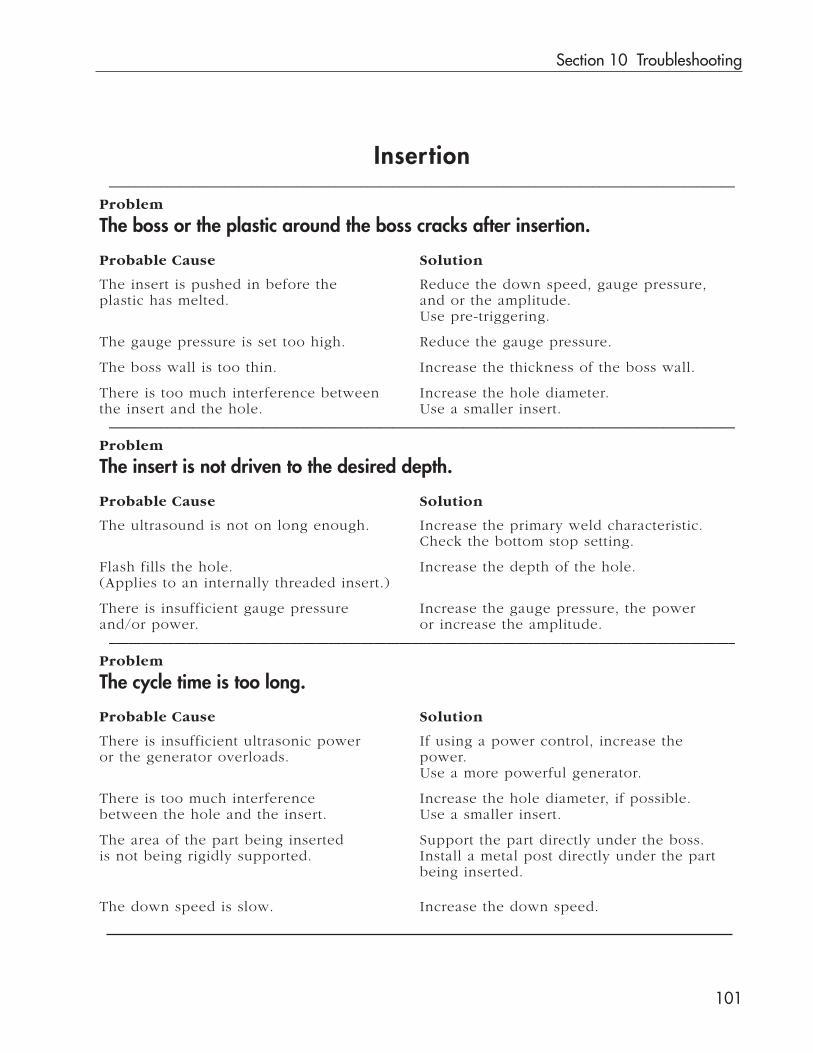
Section 10 Troubleshooting
101
Insertion_________________________________________________________________________________________________
Problem
The boss or the plastic around the boss cracks after insertion.
Probable Cause Solution
The insert is pushed in before the Reduce the down speed, gauge pressure,plastic has melted. and or the amplitude.
Use pre-triggering.
The gauge pressure is set too high. Reduce the gauge pressure.
The boss wall is too thin. Increase the thickness of the boss wall.
There is too much interference between Increase the hole diameter.the insert and the hole. Use a smaller insert.
_________________________________________________________________________________________________
Problem
The insert is not driven to the desired depth.
Probable Cause Solution
The ultrasound is not on long enough. Increase the primary weld characteristic.Check the bottom stop setting.
Flash fills the hole. Increase the depth of the hole.(Applies to an internally threaded insert.)
There is insufficient gauge pressure Increase the gauge pressure, the powerand/or power. or increase the amplitude.
_________________________________________________________________________________________________
Problem
The cycle time is too long.
Probable Cause Solution
There is insufficient ultrasonic power If using a power control, increase theor the generator overloads. power.
Use a more powerful generator.
There is too much interference Increase the hole diameter, if possible.between the hole and the insert. Use a smaller insert.
The area of the part being inserted Support the part directly under the boss.is not being rigidly supported. Install a metal post directly under the part
being inserted.
The down speed is slow. Increase the down speed.

Ultra 15 kHz Assembly System User’s Manual
102
Insertion_________________________________________________________________________________________________
Problem
Plastic flows over the top of the insert.
Probable Cause Solution
The weld time is too long. Decrease the primary weld characteristic.
The insert is being driven too deep. Reset the bottom stop.
There is too much interference Increase the hole diameter, if possible.between the hole and the insert. Use smaller inserts._________________________________________________________________________________________________
Problem
Melted plastic fills the hole. (Applies to internally threaded inserts.)
Probable Cause Solution
The insert is too long or the hole is Use a shorter insert ortoo shallow. make the hole deeper.
There is too much interference Increase the hole diameter.between the hole and the insert. Use smaller inserts.
The insert is being driven too deep. Reset the bottom stop.Decrease the primary weld characteristic._________________________________________________________________________________________________

Section 10 Troubleshooting
103
Staking_________________________________________________________________________________________________
Problem
A ragged or irregularly shaped stake head is formed.
Probable Cause Solution
The staking cavity is too large. Change to a smaller cavity in the horn.
The volume of plastic in the stud is Increase the stud height/diameter.insufficient.
The stud is melting at the base. See the problem on the next page titled,The base is melting before the head forms.
_________________________________________________________________________________________________
Problem
There is excessive flash around the stake head.
Probable Cause Solution
The staking cavity is too small. Use a larger cavity in the horn.
The volume of plastic in the stud Decrease the stud height and/or theis excessive. diameter.
The stud is not centered in the Center the stud under the horn cavity.horn cavity.
_________________________________________________________________________________________________
Problem
The surface below the stake head is distorted.
Probable Cause Solution
The part is not supported directly Support the fixture with a metal postbeneath the stud being staked. under the stud being staked.
The trigger force is too high. Reduce the trigger force.Use pre-triggering.
_________________________________________________________________________________________________
Problem
There is a loose fit between the staked head and the part being attached.
Probable Cause Solution
The hole diameter relative to Reduce the hole diameter.the stud diameter is too large.
Continued
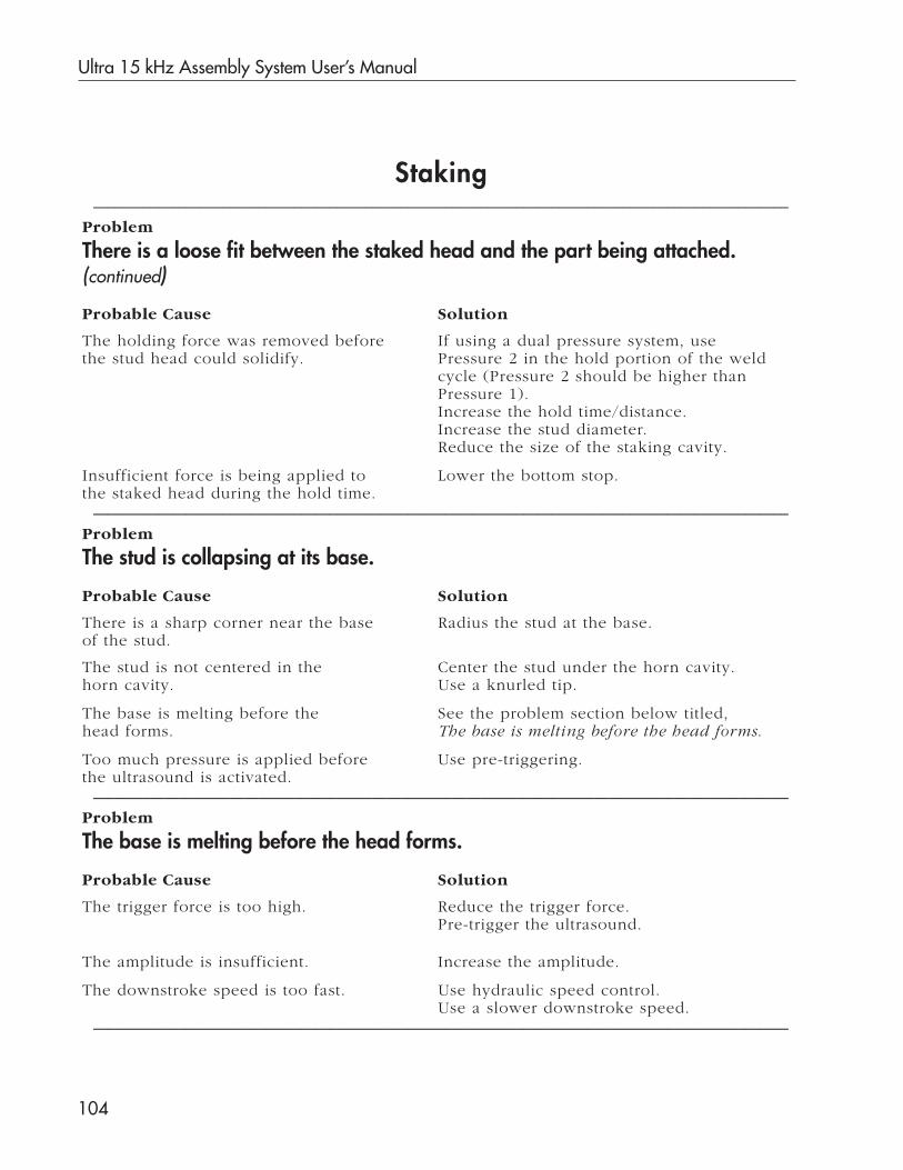
Ultra 15 kHz Assembly System User’s Manual
104
Staking_________________________________________________________________________________________________
Problem
There is a loose fit between the staked head and the part being attached.(continued)
Probable Cause Solution
The holding force was removed before If using a dual pressure system, usethe stud head could solidify. Pressure 2 in the hold portion of the weld
cycle (Pressure 2 should be higher thanPressure 1).Increase the hold time/distance.Increase the stud diameter.Reduce the size of the staking cavity.
Insufficient force is being applied to Lower the bottom stop.the staked head during the hold time.
_________________________________________________________________________________________________
Problem
The stud is collapsing at its base.
Probable Cause Solution
There is a sharp corner near the base Radius the stud at the base.of the stud.
The stud is not centered in the Center the stud under the horn cavity.horn cavity. Use a knurled tip.
The base is melting before the See the problem section below titled,head forms. The base is melting before the head forms.
Too much pressure is applied before Use pre-triggering.the ultrasound is activated.
_________________________________________________________________________________________________
Problem
The base is melting before the head forms.
Probable Cause Solution
The trigger force is too high. Reduce the trigger force.Pre-trigger the ultrasound.
The amplitude is insufficient. Increase the amplitude.
The downstroke speed is too fast. Use hydraulic speed control.Use a slower downstroke speed.
_________________________________________________________________________________________________
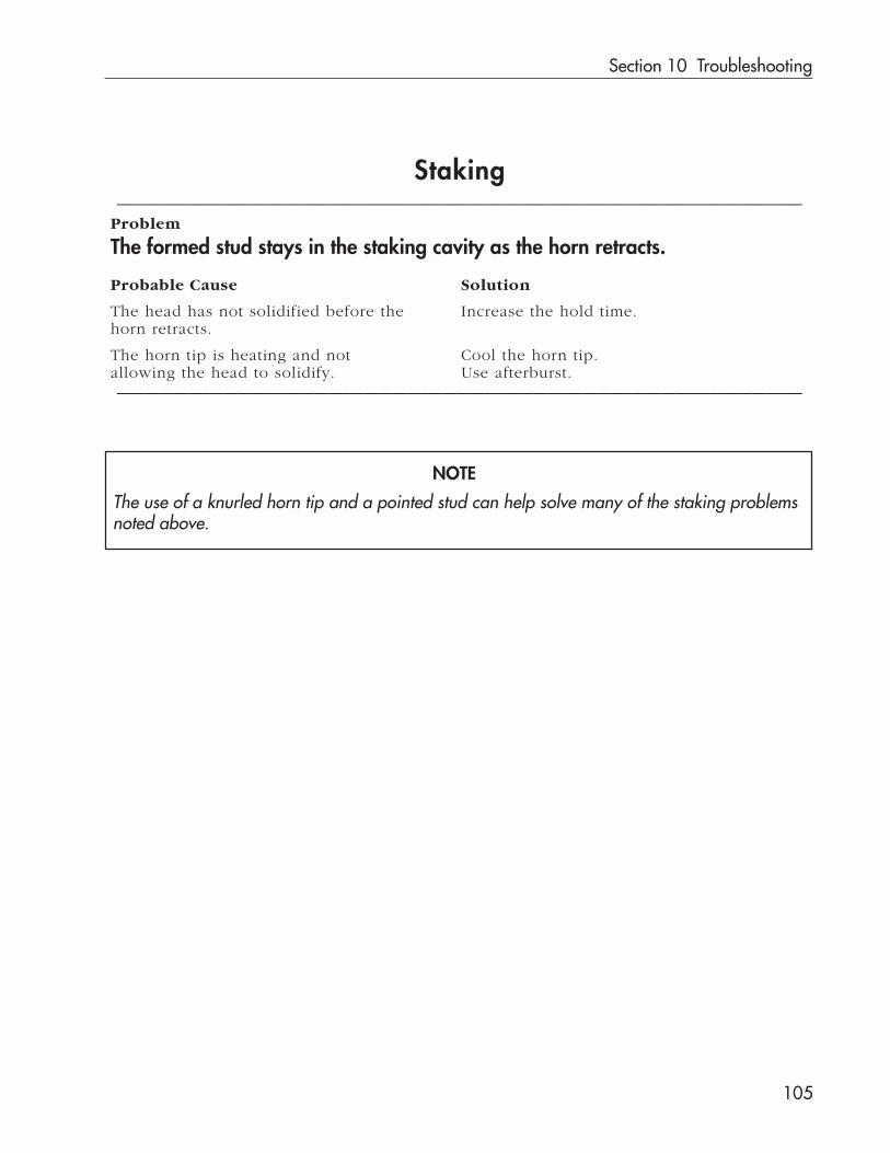
Section 10 Troubleshooting
105
Staking_________________________________________________________________________________________________
Problem
The formed stud stays in the staking cavity as the horn retracts.
Probable Cause Solution
The head has not solidified before the Increase the hold time.horn retracts.
The horn tip is heating and not Cool the horn tip.allowing the head to solidify. Use afterburst._________________________________________________________________________________________________
The use of a knurled horn tip and a pointed stud can help solve many of the staking problemsnoted above.
NOTE

Ultra 15 kHz Assembly System User’s Manual
106
Continuous Welding_________________________________________________________________________________________________
Problem
Seal does not meet strength requirements.
Probable Cause Solution
Material traveling too quickly. Decrease speed.
Not enough amplitude. Increase booster ratio.
Inconsistent blends of synthetic material. Evaluate material._________________________________________________________________________________________________
Problem
Welding is inconsistent.
Probable Cause Solution
Nonuniform amplitude horn. Have horn analyzed for amplitude uniformity.
Variations in anvil (fixture). Check fixture design and dimensions.
Inconsistency of material. Evaluate material._________________________________________________________________________________________________
Problem
Seal area too great, causes flash.
Probable Cause Solution
Material traveling too slowly. Increase speed.
Too much amplitude. Reduce booster ratio.
Excessive air pressure. Reduce air pressure._________________________________________________________________________________________________
Problem
Transducer and/or horn heating up.
Probable Cause Solution
Not enough air flow to dissipate Continuous duty applications requireheat buildup. cooling air (in some applications refriger-
ated air). Supply air to the stack interfacesand the horn tips.
_________________________________________________________________________________________________

Section 10 Troubleshooting
107
Continuous Welding_________________________________________________________________________________________________
Problem
Excessive horn wear.
Probable Cause Solution
Metal-to-metal contact between Use carbide inserts or coat horn facethe horn and anvil. with carbide.
Reduce metal-to-metal contact._________________________________________________________________________________________________
Problem
Overloading generators.
Probable Cause Solution
Loose stack components. Disassemble, clean and reassemble stack.
Horn failure. Replace horn.
Transducer failure. Replace transducer.
Booster failure. Replace booster.
Stack frequency shifted out of tolerance. Cool stack with air.
_________________________________________________________________________________________________

Ultra 15 kHz Assembly System User’s Manual
108
Equipment TroubleshootingProblem
Generator Output Power Level Meter indicates OVERLOAD.System components may be hot.
Probable Cause Solution
Stack vibrating outside Auto-Trac range. Perform the Operational Stack Test foundin Section 6.
Horn loose at booster. Tighten.
Booster loose at transducer. Tighten.
Horn contacts fixutre during weld cycle.
Ultrasound cable connections loose. Tighten.
Adjust fixture. Adjust stack components. Raise themechanical stop. Also recalculate measurements ofpart, energy director, etc. Make necessaryprogramming changes to the Ultra-Com.
Welding pressure too high. Adjust pressure setting.
Problem
Ultrasound signal does not start.
Probable Cause Solution
No power to generator or Ultra-Com. Restore power.
ON/OFF AC power switches in OFFpositon.
Turn power switches ON.
Overload protection circuitry ingenerator shuts down the ultrasoundsignal because stack is vibrating outsidethe Auto-Trac range.
Perform the Operational Stack Test found inSection 6.
Generator ultrasound signal indicator lightdoes not glow.
Restore power to the generator, and twist theOPERATE/STOP/TEST selector switch to the TESTposition for a moment.

Section 10 Troubleshooting
109
Problem
Ultrasound signal does not start (continued).Ultrasound cable is loose, not connected, ornot conducting.
Make sure cable is connected and snug. Mayneed to replace it.
Press/thruster contact leaf not making propercontact with transducer’s contact button.
Clean any dirt or corrosion from contact leafand contact button. Check that there is properalignment of contact leaf with transducercontact button.
Problem
Press/thruster does not move down.Loose power cord(s), or not plugged in tothe receptacle.
Tighten the power cord(s) and make sure it isplugged in to the receptacle.
AC power switch(es) on the Ultra-Com and/or generator are in the OFF position.
Make sure AC power switches are switchedON.
Down speed valve adjusted for no air flow.
Connect and/or tighten the cables. See CableConnections in Section 2.
If using push button activation switches to start cycle:
Activation switch cables not connectedproperly.
Connect cables properly.
Activation switches are defective. Replace switches.
Activation switches not held closed for thecorrect amount of time.
These normally open switches must be heldclosed until the ultrasound signal starts.
Activation switches held closed preventingnext cycle from starting.
Switches must be released between cycles.
Activation switches are not depressed at thesame time.
Depress the switches simultaneously.
Continued
Air filter clogged. Clean/replace air filter. Source air: clean, dry andat a higher pressure than expected outputpressure in the 80-100 psi range.
Ultra-Com INITIATE MODE not properlyset.
From PROCESS CONTROL, select INITIATE MODE,then MANUAL. See Ultra-Com User’s Manual.
CAUTIONTurn OFF electrical power before connecting or disconnecting cables fromany device. Equipment damage may occur.
Cables not connected or loose.
Adjust down speed valve for proper air flow.
Mechanical Stop adjusted for no travel. Adjust Mechanical Stop knob counterclockwise.
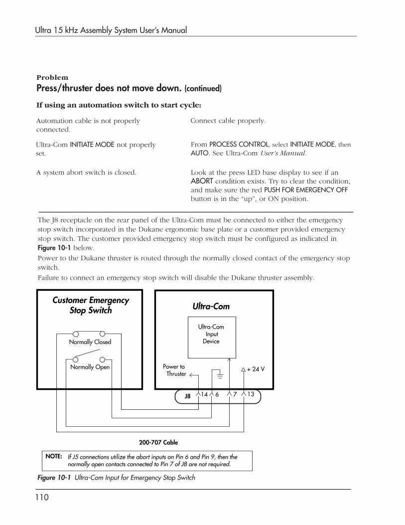
Ultra 15 kHz Assembly System User’s Manual
110
Problem
Press/thruster does not move down. (continued)
If using an automation switch to start cycle:
Automation cable is not properlyconnected.
Connect cable properly.
Ultra-Com INITIATE MODE not properlyset.
From PROCESS CONTROL, select INITIATE MODE, thenAUTO. See Ultra-Com User’s Manual.
A system abort switch is closed. Look at the press LED base display to see if anABORT condition exists. Try to clear the condition,and make sure the red PUSH FOR EMERGENCY OFFbutton is in the “up”, or ON position.
The J8 receptacle on the rear panel of the Ultra-Com must be connected to either the emergencystop switch incorporated in the Dukane ergonomic base plate or a customer provided emergencystop switch. The customer provided emergency stop switch must be configured as indicated inFigure 10-1 below.
Power to the Dukane thruster is routed through the normally closed contact of the emergency stopswitch.
Failure to connect an emergency stop switch will disable the Dukane thruster assembly.
Figure 10-1 Ultra-Com Input for Emergency Stop Switch
Customer EmergencyStop Switch
Normally Closed
Ultra-Com InputDevice
Ultra-Com
J8 14 13
200-707 Cable
Normally Open
6 7
NOTE: If J5 connections utilize the abort inputs on Pin 6 and Pin 9, then the normally open contacts connected to Pin 7 of J8 are not required.
Power to Thruster
+ 24 V
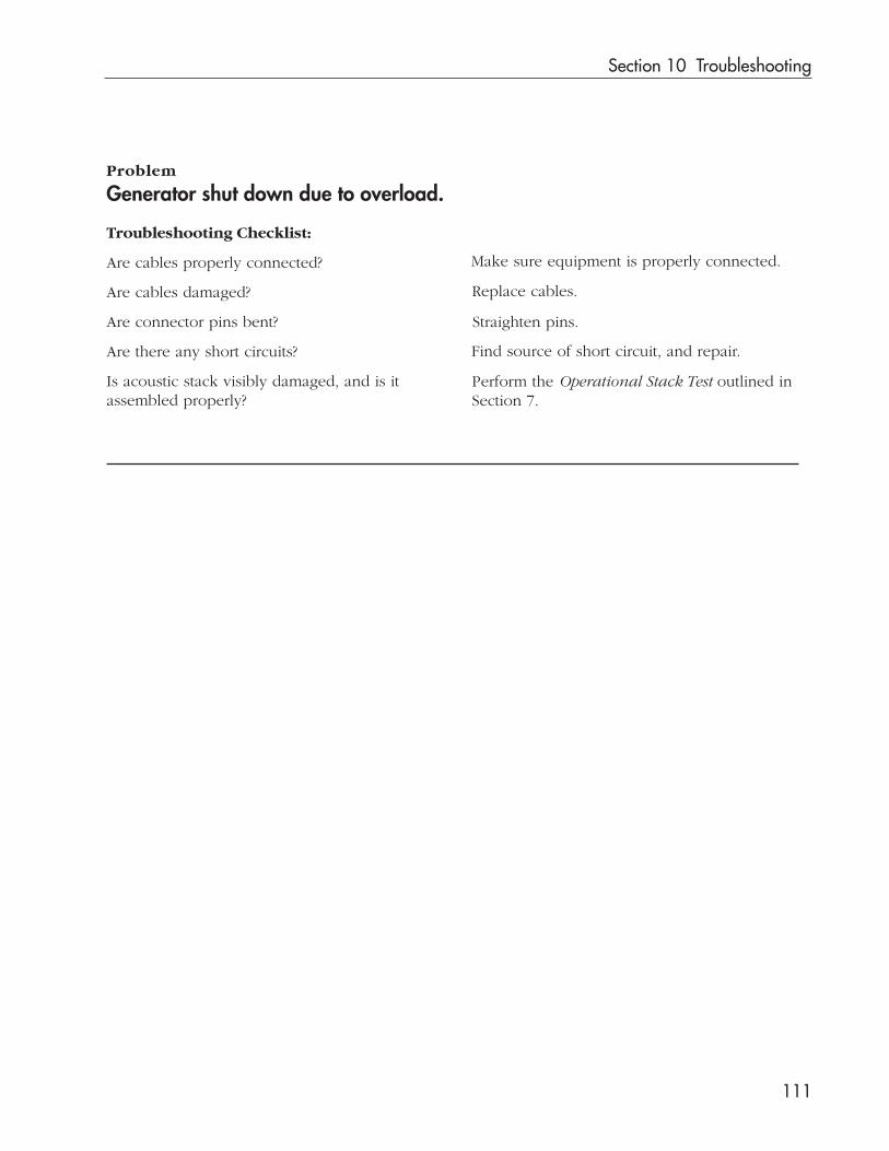
Section 10 Troubleshooting
111
Problem
Generator shut down due to overload.
Troubleshooting Checklist:
Are cables properly connected?
Are cables damaged?
Are connector pins bent?
Are there any short circuits?
Is acoustic stack visibly damaged, and is itassembled properly?
Perform the Operational Stack Test outlined inSection 7.
Straighten pins.
Replace cables.
Make sure equipment is properly connected.
Find source of short circuit, and repair.

Ultra 15 kHz Assembly System User’s Manual
112
This page intentionally left blank

Dukane Corporation
Dukane Corporation Contacts and Warranty
SECTION 11

Dukane Corporation
This page intentionally left blank
Section 11 Dukane Corporation Contacts and Warranty
113
Local SupportYour local Dukane representative can answer all of your
questions regarding Dukane equipment, as well as provide
information on pending orders and quotations. Each Dukane
representative has received factory training and can assist you
in all phases of project life cycle.
Try our Website
Dukane Corporation is on the worldwide web at:
http://www.dukcorp.com/usand then go to your area of interest.
Contacts in the Ultrasonics Division
Main Phone: (630) 797–4900
Sales: (630) 797–4918
Fax: (630) 797–4949
Service & Parts Fax: (630) 584–0796
See the next page for department extensions.
Mailing Address: Dukane Ultrasonics2900 Dukane DriveSt. Charles, IL 60174 USA
TIPAt the website you can:• Get an introduction to a
variety of joining tech-nologies.
• Learn about our productsand see layout drawings.
• Check out the FrequentlyAsked Questions section.
• Order literature.• View a list of educational
seminars.
Contacting Dukane CorporationWhen contacting Dukane, especially if calling about a service-relatedproblem, be prepared to give this information:
• DPC model number, firmware version, serial number, and line voltage.
• Any messages from the DPC display
• MMI model number and firmware version
• Description of the problem and steps taken to resolve it
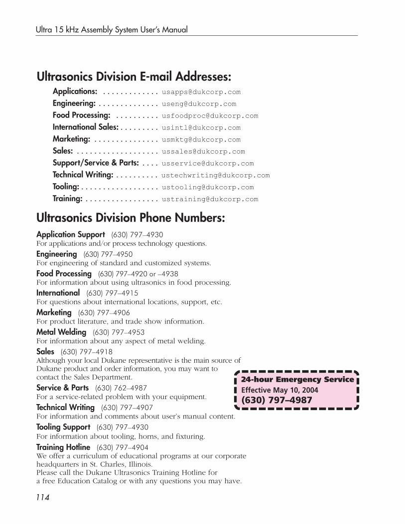
Ultra 15 kHz Assembly System User’s Manual
114
Applications: ............. [email protected]
Engineering: .............. [email protected]
Food Processing: .......... [email protected]
International Sales:......... [email protected]
Marketing: ............... [email protected]
Sales: ................... [email protected]
Support/Service & Parts: .... [email protected]
Technical Writing: .......... [email protected]
Tooling:.................. [email protected]
Training: ................. [email protected]
Ultrasonics Division Phone Numbers:Application Support (630) 797–4930For applications and/or process technology questions.
Engineering (630) 797–4950For engineering of standard and customized systems.
Food Processing (630) 797–4920 or –4938For information about using ultrasonics in food processing.
International (630) 797–4915For questions about international locations, support, etc.
Marketing (630) 797–4906For product literature, and trade show information.
Metal Welding (630) 797–4953For information about any aspect of metal welding.
Sales (630) 797–4918Although your local Dukane representative is the main source ofDukane product and order information, you may want tocontact the Sales Department.
Service & Parts (630) 762–4987For a service-related problem with your equipment.
Technical Writing (630) 797–4907For information and comments about user’s manual content.
Tooling Support (630) 797–4930For information about tooling, horns, and fixturing.
Training Hotline (630) 797–4904We offer a curriculum of educational programs at our corporateheadquarters in St. Charles, Illinois.Please call the Dukane Ultrasonics Training Hotline fora free Education Catalog or with any questions you may have.
Ultrasonics Division E-mail Addresses:
24-hour Emergency ServiceEffective May 10, 2004(630) 797–4987

Section 11 Dukane Corporation Contacts and Warranty
115
Subject to the terms, limitations and exclusions set forth below, Dukane Corporation IAS Division (Dukane) warrants to the original Pur-
chaser, unless otherwise expressly agreed to in writing by Dukane, that all equipment and tooling designed and built by Dukane will be free
from defects in material or workmanship. Normal wear items are not covered by this warranty. Warranty duration shall be defined as
documented herein and in conjunction with any exceptions or exclusions in the accompanying Dukane quotation to the Purchaser.
All Dukane warranties commence on the date of the original shipment of the equipment or tooling, and duration is based upon a singleshift per day, five day per week operation. The warranty period on rentals of new equipment that are converted to a purchase are deemedto have commenced on the initial date of rental.
These warranties are limited to equipment and tooling operated and maintained per Dukane’s written instructions, and used undernormal operating conditions. These warranties do not include normal wear or normal wear items, and do not cover damage attributableto misuse, improper installation, faulty repair, unauthorized alteration or modification, neglect, or accident. Misuse includes operation ofequipment with tooling that is not qualified for the equipment or properly installed on the equipment.
The warranty on all Dukane equipment and tooling purchased and installed in North America is a parts and labor warranty only. Equip-ment installed outside of North America, regardless of where it was purchased, is covered by Dukane’s International Warranty Policy. Inall cases, when on-site service is required, Travel & Living (T&L) expenses will be billed at cost. Warranty service labor (including traveltime) at the customer’s site is provided on a Monday through Friday (excluding holidays), 7 a.m. to 7 p.m. basis. Any warranty servicerequested outside of these hours is available on a charge basis equal to 150% of Dukane’s prevailing rate for technical service work.
Any equipment or tooling that proves to be defective in material or workmanship during the stated warranty period will be repaired orreplaced at the sole discretion of Dukane Corporation when Dukane is promptly notified in writing. During the warranty period, defectiveequipment, components, or tooling that are returned properly packed with all transportation charges prepaid will be repaired or replacedand returned to the end-user without charge. Shipments of warranty parts will be via standard, non-expedited delivery service. Expeditedshipment requests are subject to freight charges to the Purchaser.
Computers, PLCs, CRTs, LCDs, touch screens, and keyboards separate and/or incorporated as an integral part of a system will carry aone (1) year warranty from the date of shipment when used under normal operating conditions, and not subjected to misuse, abuse, orneglect. For all other equipment, components, or parts included in equipment or systems from Dukane, but not manufactured by Dukane
or its affiliates, this warranty shall be limited in time and extent to the warranty given to Dukane by the OEM.
EQUIPMENT WARRANTY EXCLUSIONS OR EXCEPTIONS:When specified in our quotation, a limited warranty may apply to certain components of the equipment, and/or for certain types ofapplications of the equipment, including those noted below.
❑ This warranty is void if the ultrasonic welder and/or tooling [i.e., horn(s) and fixture(s)] are used for applications requiring metal-to-metal contact, when the ultrasonic exposure period (weld cycle) exceeds 250 milliseconds.
❑ Ultrasonic Equipment and tooling used in continuous duty cycle modes such as, but not limited to, continuous cut and seal, andfood processing are warranted for 2000 hours or 12 months from shipment, whichever occurs first.
❑ Any ultrasonic horn or tool quoted and sold as “Experimental” is not warranted.
❑ This warranty does not cover failures of equipment and components attributable to improper cooling or overheating of thetransducer.
❑ Ultrasonic Horn Analyzers have a 12-month warranty.
❑ Ultrasonic Transducers have a one-time replacement warranty.
❑ Normal wear items and consumables excluded from any warranty coverage include, but are not limited to, filters, fuses, light bulbs,
lubricants, gaskets and seals, cast urethane fixture components, laser flashlamps, laser beam delivery optics, and lasing gases.
The forgoing warranty is the sole and exclusive warranty and is made in lieu of all other warranties, express, impliedor statutory, including without limitation any warranties of merchantability, fitness for a particular purpose, descrip-tion, quality, productiveness or any other warranty. The remedy set forth in this warranty policy is the sole andexclusive remedy of Purchaser and in no event shall Dukane be liable for any compensatory, consequential, special,punitive or contingent damages or for damages arising from any delay in performance by Dukane under this warranty.
Equipment Type Equipment Warranty Duration Other Comments
Custom Systems 12 months on all Dukane designed and built content Dukane standard product included in custom systems that is not part of our standard product. are covered by the applicable product warranty.
Hot Plate Welder 24 months none
Laser Welder For all laser sources, Original equipment All internal laser optics and external beam delivery manufacturer (OEM) warranty is applicable. optics are warranted for only 30 days.
Spin Welder 24 months none
Thermal Press 24 months none
Ultrasonic Welder 36 months See WARRANTY EXCLUSIONS OR EXCEPTIONS below.
Vibration Welder 24 months none
All Production 12 months, one-time replacement. (6-month, noneTooling one-time replacement for carbide tipped horns)
Prototype Tooling • All tooling made from Renshape 460 (Renwood) Prototype Renshape 460 (Renwood) tools employ are only warranted for 200 part-cycles. reusable content, and therefore remain the property
• All other prototype tooling is warranted as of Dukane.
described in each specific proposal.
DUKANE CORPORATION NORTH AMERICAN WARRANTY POLICY
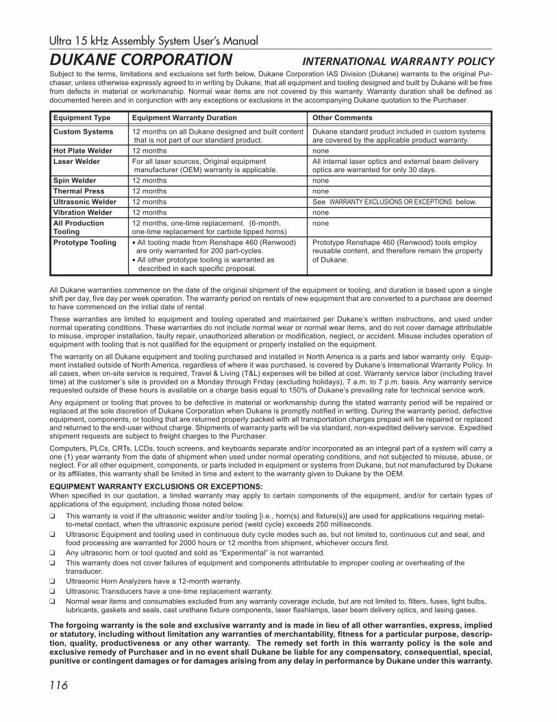
Ultra 15 kHz Assembly System User’s Manual
116
Subject to the terms, limitations and exclusions set forth below, Dukane Corporation IAS Division (Dukane) warrants to the original Pur-
chaser, unless otherwise expressly agreed to in writing by Dukane, that all equipment and tooling designed and built by Dukane will be free
from defects in material or workmanship. Normal wear items are not covered by this warranty. Warranty duration shall be defined as
documented herein and in conjunction with any exceptions or exclusions in the accompanying Dukane quotation to the Purchaser.
All Dukane warranties commence on the date of the original shipment of the equipment or tooling, and duration is based upon a singleshift per day, five day per week operation. The warranty period on rentals of new equipment that are converted to a purchase are deemedto have commenced on the initial date of rental.
These warranties are limited to equipment and tooling operated and maintained per Dukane’s written instructions, and used undernormal operating conditions. These warranties do not include normal wear or normal wear items, and do not cover damage attributableto misuse, improper installation, faulty repair, unauthorized alteration or modification, neglect, or accident. Misuse includes operation ofequipment with tooling that is not qualified for the equipment or properly installed on the equipment.
The warranty on all Dukane equipment and tooling purchased and installed in North America is a parts and labor warranty only. Equip-ment installed outside of North America, regardless of where it was purchased, is covered by Dukane’s International Warranty Policy. Inall cases, when on-site service is required, Travel & Living (T&L) expenses will be billed at cost. Warranty service labor (including traveltime) at the customer’s site is provided on a Monday through Friday (excluding holidays), 7 a.m. to 7 p.m. basis. Any warranty servicerequested outside of these hours is available on a charge basis equal to 150% of Dukane’s prevailing rate for technical service work.
Any equipment or tooling that proves to be defective in material or workmanship during the stated warranty period will be repaired orreplaced at the sole discretion of Dukane Corporation when Dukane is promptly notified in writing. During the warranty period, defectiveequipment, components, or tooling that are returned properly packed with all transportation charges prepaid will be repaired or replacedand returned to the end-user without charge. Shipments of warranty parts will be via standard, non-expedited delivery service. Expeditedshipment requests are subject to freight charges to the Purchaser.
Computers, PLCs, CRTs, LCDs, touch screens, and keyboards separate and/or incorporated as an integral part of a system will carry aone (1) year warranty from the date of shipment when used under normal operating conditions, and not subjected to misuse, abuse, orneglect. For all other equipment, components, or parts included in equipment or systems from Dukane, but not manufactured by Dukane
or its affiliates, this warranty shall be limited in time and extent to the warranty given to Dukane by the OEM.
EQUIPMENT WARRANTY EXCLUSIONS OR EXCEPTIONS:When specified in our quotation, a limited warranty may apply to certain components of the equipment, and/or for certain types of
applications of the equipment, including those noted below.
❑ This warranty is void if the ultrasonic welder and/or tooling [i.e., horn(s) and fixture(s)] are used for applications requiring metal-to-metal contact, when the ultrasonic exposure period (weld cycle) exceeds 250 milliseconds.
❑ Ultrasonic Equipment and tooling used in continuous duty cycle modes such as, but not limited to, continuous cut and seal, andfood processing are warranted for 2000 hours or 12 months from shipment, whichever occurs first.
❑ Any ultrasonic horn or tool quoted and sold as “Experimental” is not warranted.
❑ This warranty does not cover failures of equipment and components attributable to improper cooling or overheating of thetransducer.
❑ Ultrasonic Horn Analyzers have a 12-month warranty.
❑ Ultrasonic Transducers have a one-time replacement warranty.
❑ Normal wear items and consumables excluded from any warranty coverage include, but are not limited to, filters, fuses, light bulbs,lubricants, gaskets and seals, cast urethane fixture components, laser flashlamps, laser beam delivery optics, and lasing gases.
The forgoing warranty is the sole and exclusive warranty and is made in lieu of all other warranties, express, impliedor statutory, including without limitation any warranties of merchantability, fitness for a particular purpose, descrip-tion, quality, productiveness or any other warranty. The remedy set forth in this warranty policy is the sole andexclusive remedy of Purchaser and in no event shall Dukane be liable for any compensatory, consequential, special,punitive or contingent damages or for damages arising from any delay in performance by Dukane under this warranty.
Equipment Type Equipment Warranty Duration Other Comments
Custom Systems 12 months on all Dukane designed and built content Dukane standard product included in custom systems that is not part of our standard product. are covered by the applicable product warranty.
Hot Plate Welder 12 months none
Laser Welder For all laser sources, Original equipment All internal laser optics and external beam delivery manufacturer (OEM) warranty is applicable. optics are warranted for only 30 days.
Spin Welder 12 months none
Thermal Press 12 months none
Ultrasonic Welder 12 months See WARRANTY EXCLUSIONS OR EXCEPTIONS below.
Vibration Welder 12 months none
All Production 12 months, one-time replacement. (6-month, noneTooling one-time replacement for carbide tipped horns)
Prototype Tooling • All tooling made from Renshape 460 (Renwood) Prototype Renshape 460 (Renwood) tools employ are only warranted for 200 part-cycles. reusable content, and therefore remain the property
• All other prototype tooling is warranted as of Dukane.
described in each specific proposal.
DUKANE CORPORATION INTERNATIONAL WARRANTY POLICY

Dukane Corporation
Specifications
SECTION 12

Dukane Corporation
This page intentionally left blank
Section 12 Specifications
117
The Ultra-Com complies with the following requirements:
• the limits for FCC measurement procedure MP-5, “Methodsof Measurement of Radio Noise Emissions from ISM Equip-ment”, pursuant to FCC Title 47 Part 18 for UltrasonicEquipment
CAUTIONDO NOT make any modifications to the Ultra-Com, to the generator, to the press/thruster orto associated cables because the changesmay result in violating one or more regula-
tions under which the equipment is manufactured.
Regulatory Agency Compliance
Specifications
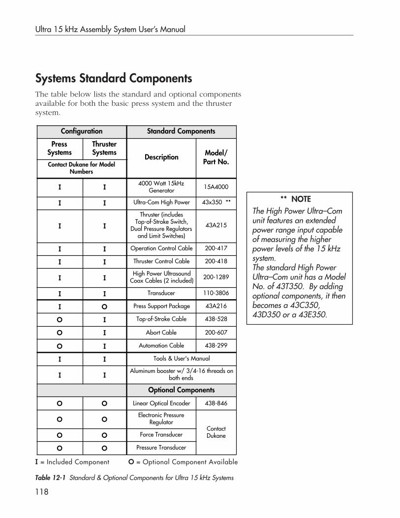
Ultra 15 kHz Assembly System User’s Manual
118
Systems Standard Components
Table 12-1 Standard & Optional Components for Ultra 15 kHz Systems
I = Included Component O = Optional Component Available
The table below lists the standard and optional componentsavailable for both the basic press system and the thrustersystem.
** NOTEThe High Power Ultra–Comunit features an extendedpower range input capableof measuring the higherpower levels of the 15 kHzsystem.The standard High PowerUltra–Com unit has a ModelNo. of 43T350. By addingoptional components, it thenbecomes a 43C350,43D350 or a 43E350.
Configuration Standard Components
PressSystems
ThrusterSystems
Description Model/Part No.Contact Dukane for Model
Numbers
I I 4000 Watt 15kHzGenerator 15A4000
I I Ultra-Com High Power 43x350 **
I I
Thruster (includesTop-of-Stroke Switch,
Dual Pressure Regulatorsand Limit Switches)
43A215
I I Operation Control Cable 200-417
I I Thruster Control Cable 200-418
I IHigh Power Ultrasound
Coax Cables (2 included) 200-1289
I I Transducer 110-3806
I O Press Support Package 43A216
O I Top-of-Stroke Cable 438-528
O I Abort Cable 200-607
O I Automation Cable 438-299
I I Tools & User's Manual
I IAluminum booster w/ 3/4-16 threads on
both ends
Optional Components
O O Linear Optical Encoder 438-846
O OElectronic Pressure
RegulatorContactDukaneO O Force Transducer
O O Pressure Transducer

Section 12 Specifications
119
System RequirementsCompressed AirThe thruster requires 80-100 psi of clean, dry air.Maximum available clamp pressure is 175 lb @100 psi with astandard 1.5 inch diameter (38.1 mm) air cylinder.
Electrical
Space
Press dimensions are shown in detail on the next page.
Weight
Press & Thruster – 322 lb (813 kg); thruster only-93 lb (49 kg)
NOTECompressed air must bedelivered at a higherpressure than the expectedoutput pressure and in arange of 80-100 psi.
Ultra 4000 Generator – 240 VAC 50/60 Hz single phase@ 30 A3 wire, 2 pole, grounded outlet, withlocking type NEMA L6-30R receptacle.
Generator will meet 4000 Watt specification only at 240VAC.Operation at less than 240VAC will result in reduced output.Operation above 240VAC may result in excessive power output.
Ultra-Com – 120 VAC 50/60 Hz @ 0.5 A
Press/Thruster – 24 vdc @ 2 amps, obtained from the Ultra-Com
Ultra-Com – 16 lb (7.3 kg)
Generator – 50 lb (22.7 kg)
Table 12-2 Component Dimensions
Add about 5 inches (125 mm) space above the press, and to therear of the Ultra-Com and generator for cable connections. Allow6 inches (150 mm) of space on either side of the Ultra-Com andgenerator for air circulation.
NOTE
ComponentDimensions – inches (mm)
Height Width Depth
Press 62.25 (1580) 18.6 (475) 24.8 (630)
Ultra-Com 3.5 (90) 14.5 (370) 13 (330)
Generator 5.5 (140) 19.0 (485) 20.5 (520)

Ultra 15 kHz Assembly System User’s Manual
120
Dimensions
Figure 12-1 Press Front View
Figure 12-3 Top View, Press Base
Figure 12-2 Press Left Side View
inches (mm)
5.82(143)
LINEARENCODER
(OPTIONAL)
PRESS RACK& PINION HEIGHT
ADJUSTMENTWHEEL
AIR CYLINDERCOUNTER-BALANCE
PRESS/HORN
CENTERLINE
18.58 (472)
4.50(114)
24.83(631)
40.00(1016)
14.75(375)
38.66(982)
18.85 max(479)
(PRESS SHOWN AT LOWEST POSITION)
LIFTINGEYE-BOLT
12.38(314)
4.74(120)
44.75(1137)
6.20(157)
17.50 max(444)
7.00 min(178)
24.83(631)
20.88(530)
13.25(337)
18.58(472)
12.38(314)
0.50
DIAHOLES
6.00(152.4)
RAD
10mm TAP
4.92(125.0)10mm TAP 2 Holes

Section 12 Specifications
121
Table 12-3 Miscellaneous Dimensions
Operating EnvironmentOperate the press/thruster within these guidelines:
Temperature: 40 - 100° F (5 - 38° C)
Pressure: Ambient
Air Particulates: Keep the equipment dry.
Do not expose to rain or moisture.
Minimize exposure to, dust, dirt, smokeand mold.
CAUTIONMake sure the compressed air feeding thepress/thruster is clean and dry.Damage to the equipment will occur if the aircontains moisture or oil.
ItemInches (mm)
Height Width Depth Other
Thruster 38.66 (982) 5.82 (143) At deepest point:10.00 (254)
Base 4.74 (120) 18.56 (471) 24.83 (631)
Column 40.00 (1016) Diameter at base:7.50 (191)
Column C.L. toHorn C.L.
12.38 (314)
Horn C.L. toRear ofThruster
6.20 (157)
Usable Throat 8.50 (216)
Stroke 7.00 (178)

Ultra 15 kHz Assembly System User’s Manual
122
Figure 12-4 Locating Model and Serial Numbers
Identification Numbers
Model & Serial Numbers
Thruster Model & Serial Numbers
Use Figure 12-4 as a guide to locate model and serial numbersfor your Ultra-Com, generator, thruster and press.

Dukane Corporation
Index

Dukane Corporation
This page intentionally left blank

Index
AAcoustic Stack, see Stack
Activation Switches, 38
Adjustment Knobs, see Controls
AirGauge, see ControlsFilter, 89Lockout Valve, 35, 36, 88Supply, 119
Auto-Trac Tuning, 67
BBase, see Press Base
Before Unpacking, 11
Burnished Areas, 82
CCable Part Numbers, 17, 23, 119
also see Connections
ChangesMaking System, 80To Stack Components, 46-52
Checklist, Daily Start-up, 77
Components, Standard System, 118
Compressed Air, 11, 19
ConnectionsCable, 16-20
Air Connection, 19
Press System,16-19Optional, 20Thruster System, 22-25
ControlsGenerator Front panel
AC Power, 61OPERATE/STOP/TEST, 61Power Level, 62
Press BaseActivation Switches, 37, 38Emergency OFF Switch, 37Press Status Display, 37, 38
Rear PanelAir Lockout Valve, 35, 36
ThrusterAir Gauge, 28, 29Down Speed Control, 28, 29End Weld Adjustment Knob, 28, 33Indicator Flags, 28, 31Pressure Adjustment Knobs, 28, 30Pre-trigger Adjustment Knob, 28, 32Pressure Select Switch, 28, 30Mechanical Stop Indicator, 28, 34Trigger Control Knob, 28, 34Ultrasound Active Status Light, 28, 31
DDimensions, 11, 121
Dukane CorporationPhone, 113Website, 113E-mail, 114Warranty, 115-116

Ultra 15 kHz Assembly System User’s Manual
EElectrical Safety Frounding, 8-10
Electronic Pressure Regulator, 43
Emergency OFF Switch, 37
Emergency Stop Switch, Customer, 110
Encoder, Linear, 20, 39-42
End Weld Adjustment Knob, 33
F
Fixture Installation, 53-55
Flags, Indicator, 28, 31
Flange Template, 26
Front Panel Controls, see Controls
GGenerator, 57-65
Grounding, 58Identification Numbers, 65Installation, 60Front Panel Controls, 61-62Rear Panel, 63-64RFI Filter, 59Safety, 57Specifications, 64
Grounding Instructions, 8-10
HHealth and Safety, 6-8
Height Adjustment Handwheel, 5, 14
Hydraulic Speed Control, see Speed Con-trol
IIdentification Numbers, 65, 122
Inspections, Daily, 88
InstallationCable Connections, see ConnectionsLinear Encoder, 39-42Fixture, 53-55Placement, 13Stack, 53Thruster Only, 22-25Unpacking, 12
L
Linear EncoderKit Installation, 40-42
Load Cell, 44

Index
MMaintenance, 81-90
Press/Thruster, 88-89
Making System Changes, 80
Mechanical Stop Indicator, 28, 34
Model Numbers, 122
Mounting Hole Measurements, Fixture, 55
OOperating Environment, 121
Operation, 77-79
Operational Stack Test, 68-73
Optional ConnectionsLinear Encoder, 16, 22Top-of-Stroke Cable, 22
OSHA, 6,7
PPart Quality, 75
Plastics Health Notice, 8
Power Draw, 75
PressBase, 37Controls, 27Features, 5Maintenance, 88, 89Options, 39-44
Placement, 13Status Display, 37Without Base, 13
Pressure 1 and 2 Adjustment Knobs, seeControls
Pressure Regulator, 43
Pressure Transducer, 43
Pre-trigger Adjustment Knob, see, Controls
RRear Panel, 35
Regulatory Agency Compliance, 117
Resurfacing Mating Surfaces, 84-86
RFI Filter, 10
S
Sample Parts, Running 65
Serial Numbers, 65, 122
Specifications, 119-121
StackAssembly, 50Changing Stack Components, 46Description, 45Disassembly, 49Inspection, 82Installing, 52Maintenance, 81-83
Ultra 15 kHz Assembly System User’s Manual
Mounting Studs, 51Operational Test, 58-63Reconditioning, 84-86Removal, 47
Start-up, 78
Stopping the System, 79
System Changes, 80
TTest, System, 67-75
ThrusterConnections, 22-25Height Adjustment, 14Installing, 21-25Mounting, 22Repositioning a Clamp Handle, 14
Top of Press Connectors, 19
Top-of-Stroke Cable, 19, 22, 118
Torque ValuesBooster and Horn Stud, 87Stack Assembly, 87
Trigger Control Knob, 28, 34
TroubleshootingContinuous Welding, 106-107Equipment, 108-111Insertion, 100-102Process, 93-107Staking, 103-105Welding, 93-99
UUltra-Com
Checklist, 77Connections, 16, 17, 22, 23Description, 4Primary Weld Characteristics, 92User’s Manual, 1, 2, 80
Unpacking the Equipment, 12
User Manual Organization, 2-3
WWarranty
USA, Canada, Mexico, 115International, 116

Dukane ISOISO CERTIFICATIONDukane chose to become ISO 9001 certified inorder to demonstrate to our customers our con-tinuing commitment to being a quality vendor.By passing its audit, Dukane can assure youthat we have in place a well–defined and sys-tematic approach to quality design, manufac-turing, delivery and service. This certificate re-inforces Dukane's status as a quality vendor oftechnology and products.
To achieve ISO 9001 certification, you mustprove to one of the quality system registrargroups that you meet three requirements:1. Leadership2. Involvement3. Quality in Line Organizations and Quality
System Infrastructure.
The ISO 9001 standard establishes a minimumrequirement for these requirements and startstransitioning the company from a traditional in-spection–oriented quality system to one basedon partnership for continuous improvement. Thisconcept is key in that Dukane no longer focuseson inspection, but on individual processes.
Dukane's quality management system is basedon the following three objectives:1. Customer oriented quality. The aim is to
improve customer satisfaction.2. Quality is determined by people. The aim
is to improve the internal organization andcooperation between staff members.
3. Quality is a continuous improvement. Theaim is to continuously improve the internalorganization and the competitive position.
Dukane products are manufacturedin ISO registered facilities
ISO 9001CERTIFIED

40354200Dukane Corporation • Ultrasonics Division • 2900 Dukane Drive • St. Charles, Illinois 60174 USA • TEL (630) 797-4900 • FAX (630) 797-4949
Part No. 403–542–00
Printed in the United States of America$100.00
15kHz Assembly System User's Manual