ultrasonic transit time flowmeter ttfm100b-hh … · e-mail [email protected] web ultrasonic...
TRANSCRIPT

Mod.BM43 COM
Vers.1.0 16/11/2005
Page 1 of
121
B.M. Tecnologie Industriali Via Praimbole 13 35010 LIMENA (PD) VAT No. IT02459940280
Tel. +39 (0) 49 884.16.51 Fax +39 (0) 49 884.16.54
E-Mail [email protected] Web www.bmtecnologie.it
ULTRASONIC TRANSIT TIME FLOWMETER TTFM100B-HH-NG
HAND-HELD TYPE
INSTRUCTION MANUAL – REV. 2.2.8

Mod.BM43 COM
Vers.1.0 16/11/2005
Page 2 of
121
B.M. Tecnologie Industriali Via Praimbole 13 35010 LIMENA (PD) VAT No. IT02459940280
Tel. +39 (0) 49 884.16.51 Fax +39 (0) 49 884.16.54
E-Mail [email protected] Web www.bmtecnologie.it
INTRODUCTION 5
1. WORKING PRINCIPLE 6
1.1 TYPICAL USE 7 1.2 DESCRIPTION 8
1.3 PACKING LIST 8 1.4 INTEGRATED REAL TIME CLOCK (RTC) 9
1.5 PRODCUT ID 9 1.6 TECHNICAL FEATURES 9
2. INSTALLATION AND OPERATION 10
2.1 MEASURING POINT 10
2.2 REQUIRED CONDITIONS 11 2.3 A PRACTICAL EXAMPLE OF RAPID SETTINGS 12
2.3.1 FLUID AND PIPE’S FEATURES 12 2.3.2 DATA ENTRY 12
2.4 INSTRUCTIONS FOR CLAMP-ON SENSORS MOUNTING 17 2.5 TRANSDUCERS MOUNTING METHODS 25
2.5.1 “V” MOUNTING METHOD 27 2.5.2 “Z” MOUNTING METHOD 28
2.5.3 “W” and “N” MOUNTING METHODS 30 2.6 MOUNTING ANALYSIS 31
2.6.1 SIGNAL’S STREANGTH & QUALITY 31 2.6.2 TOTAL SPREADING TIME, TIME DIFFERENCE M93 32
2.6.3 RELATION BETWEEN CALCULATED AND MEASURED TRANSIT TIME 32
3. DISPLAY WINDOWS 33
3.1 FLOWRATE- TOTALIZERS MENU 33 3.2 INITIAL SETTINGS MENU 33
3.3 FLOWRATE UNITS MENU 34 3.4 OPTIONAL SETTING MENU 34
3.5 INPUTS/OUTPUTS MENU 34 3.6 DIAGNOSTICS MENU 35
3.7 OTHER DISPLAYS MENU 35 3.8 FLOWRATE- TOTALIZERS MENU ANALYSIS 36
3.9 INITIAL SETTING MENU ANALYSIS 39 3.10 FLOWRATE UNITS MENU ANALYSIS 46

Mod.BM43 COM
Vers.1.0 16/11/2005
Page 3 of
121
B.M. Tecnologie Industriali Via Praimbole 13 35010 LIMENA (PD) VAT No. IT02459940280
Tel. +39 (0) 49 884.16.51 Fax +39 (0) 49 884.16.54
E-Mail [email protected] Web www.bmtecnologie.it
3.11 INPUTS/OUTPUTS MENU NALYSIS 52
3.12 DIAGNOSTICS MENU ANALYSIS 61
3.13 OTHER DISPLAYS MENU ANALYSIS 62
4. DIAGNOSTICS AND PROBLEM SOLVING 64
4.1 AUTOTEST DURING SWITCHING ON AND POSSIBLE SOLUTIONS 64 4.2 ERROR CODES, CAUSES AND SOLUTIONS DURING FUNCTIONING 64
4.3 OTHER PROBLEMS & SOLUTIONS 65
5. COMMUNICATION WITH A PC AND/ OR DATA LOGGING 66
5.1 REQUIRED HARDWARE 66
5.2 COMPLETE PI-OUT OF DB9 M DOOR 66 5.3 DIRECT CONTROL – COMMUNICATION PROTOCOL 67
5.4 USE OF THE PREFIX IN THE CONTROL 68
5.5 KEYPAD CODES 69
6. APPENDIX 70
6.1 SOUNS SPEEDS IN SOLIDS 70
6.2 SOUND SPEEDS IN FLUIDS 72 6.3 SOUND SPEEDS IN WATER AT SELECTED TEMPERATURES 86
6.4 PIPE SIZE DATA 88
7. EC- DECLARATION OF CONFORMITY 93
8. DATA LOGGER INSTRUCTIONS MANUAL 96

Mod.BM43 COM
Vers.1.0 16/11/2005
Page 4 of
121
B.M. Tecnologie Industriali Via Praimbole 13 35010 LIMENA (PD) VAT No. IT02459940280
Tel. +39 (0) 49 884.16.51 Fax +39 (0) 49 884.16.54
E-Mail [email protected] Web www.bmtecnologie.it
IMPORTANT NOTICES:
1. EACH UNIT MUST BE CONNECTED TO ITS
OWN SENSORS. THE SERIAL NUMBERS OF SENSORS AND
UNITS ARE WRITTEN IN THE ID LABELS AND MUST CORRESPOND EACH OTHER.
2. THE DEVICE IS SUPPLIED WITH UNCHARGED BATTERIES. PLS CHARGE THE BATTERIES FOR 12
HOURS BEFORE USING THE DEVICE.

Mod.BM43 COM
Vers.1.0 16/11/2005
Page 5 of
121
B.M. Tecnologie Industriali Via Praimbole 13 35010 LIMENA (PD) VAT No. IT02459940280
Tel. +39 (0) 49 884.16.51 Fax +39 (0) 49 884.16.54
E-Mail [email protected] Web www.bmtecnologie.it
INTRODUCTION Thanks for buying an Ultrasonic Transit Time Flowmeter TTFM100-NG series. The device measures flowrate by calculating the spreading time of an ultrasonic wave in a liquid, going upstream and downstream into a pipe. This flowmeter is mostly used to measured the flowrate of homogeneous fluids , with a very little percentage of suspended solids and possibly without gas bubbles. Its peculiar installation makes this devices suitable for measuring aggressive fluids (acids, basic and dissolvents) or very soiling fluids(oil and fuels). The measuring system is composed of a couple of ultrasonic transducers acoustically coupled to the external pipe’s wall (it is also possible to use transducers in direct contact with fluid to be measured) and a HOST unit elaborating the sent and received signals from the transducers. The HOST unit has a DSP microprocessor, it gives signals to interfacing with the process or the control systems.
The devices main features are:
Clamp-on sensors: it is not necessary to stop the flow to install them.
AC and DC supply: 230 VAC. The time difference during the measuring process could be 0.2 ns. RS232 output. All the measures could be driven to the RS232 in order to save data into a PC or a
serial printer.

Mod.BM43 COM
Vers.1.0 16/11/2005
Page 6 of
121
B.M. Tecnologie Industriali Via Praimbole 13 35010 LIMENA (PD) VAT No. IT02459940280
Tel. +39 (0) 49 884.16.51 Fax +39 (0) 49 884.16.54
E-Mail [email protected] Web www.bmtecnologie.it
1. WORKING PRINCIPLE
When the ultrasonic wave spreads in a liquid, the flow will cause a changing in the spreading time depending on downstream or upstream current.
The ultrasonic wave going towards the same directions of the flow increases the spreading speed, while the ultrasonic wave going towards the opposite side of the flow decreases the spreading speed.
If the difference between the two spreading times is accurately measured, it would be possible to calculate the flow speed (see the following picture).
The measures are taken by 2 sensors in direct contact with the pipe’s external surface.
The UP sensor (RED) is placed on the upper side of the pipe’s external surface, the DOWN
sensor (BLUE) is placed on the lower side of the pipe’s external surface.
The sensors positions could look like a “Z” or like a “V” or a “W”, if the pipe has a small
diameter (in the previous sketch, the sensors are “Z” mounted).
The sensors are alternatively used to receive the ultrasonic pulses sent through the way
pipe - fluid - pipe.
The difference between the transmitted and received signals upstream and downstream is calculated as follows:
(1) (2) (3)
VSINCo
COS
DM
Tup
VSINCo
COS
DM
TdownTdownTup
T
SIN
DMV
**
2
*

Mod.BM43 COM
Vers.1.0 16/11/2005
Page 7 of
121
B.M. Tecnologie Industriali Via Praimbole 13 35010 LIMENA (PD) VAT No. IT02459940280
Tel. +39 (0) 49 884.16.51 Fax +39 (0) 49 884.16.54
E-Mail [email protected] Web www.bmtecnologie.it
Where: M Spreading time D Pipe’s internal diameter Ө Transmission angle Co Sound spread speed through the fluid in static conditions Tup Positive spreading time Tdown Negative spreading time V Flow Velocity The DT value is the difference of the spreading time into a homogenous fluid without gas bubbles. The equation (3) for calculating the average speed “V” could be used for all the types of fluids in ideal conditions. The fluid speed measuring is in fact conditioned by different factors which make the precision decrease: for example the dumps on the pipe are internal walls: they change the measuring principle of the transit time flow meter. TTFM100 series has are a lot of solutions trying to solve these problems, compensating the temperature influence, the dumped internal walls and the asymmetry in the speed distribution, in order to measure in critical conditions too. It is possible to adjust the zero point of the device: if the fluid is in static conditions, this operation makes the repeatability precision increase until reaching values near to 0.5%.
1.1 TYPICAL USE
Water treatment, slurry and process water pumping;
Oil and chemical industries;
Hydro-electric, cooling, anti-fire stations;
Extraction industries;
Food, paper and pharmaceutical industries;
Car industries;
Flow balancing;
Heat measuring in central systems.

Mod.BM43 COM
Vers.1.0 16/11/2005
Page 8 of
121
B.M. Tecnologie Industriali Via Praimbole 13 35010 LIMENA (PD) VAT No. IT02459940280
Tel. +39 (0) 49 884.16.51 Fax +39 (0) 49 884.16.54
E-Mail [email protected] Web www.bmtecnologie.it
1.2 DESCRIPTION
Frontal View
Top View
Bottom View
1.3 PACKING LIST
Portable ultrasonic transit time flowmeter 1 pc
Serial cable DB9.F 1 pc
Battery charger 12 VDC/ 0.5 A 1 pc Adaptor for serial connector/ battery charger 1 pc Clamp-on sensors TS2 (small)* 2 pcs Clamp-on sensors TM1 (medium) * 2 pcs Clamp-on sensors TL1 (large)* 2 pcs Spiral cable, 5mt (optional 10 mt straight cable) 2 pcs Acoustic couplant (grease) 1 pc Sensors mounting kit 2 pcs EC certification 1 pc Instruction Manual 1 pc
* depending from the type of sensors ordered by the customer

Mod.BM43 COM
Vers.1.0 16/11/2005
Page 9 of
121
B.M. Tecnologie Industriali Via Praimbole 13 35010 LIMENA (PD) VAT No. IT02459940280
Tel. +39 (0) 49 884.16.51 Fax +39 (0) 49 884.16.54
E-Mail [email protected] Web www.bmtecnologie.it
1.4 INTEGRATED REAL TIME CLOCK (RTC) The user’s settings are saved into the device’s memory for at least 2100 years in case of power failures. The device could be protected by a PASSWORD. The RTC remains active until the battery discharge tension is 1.5 V. Ref. to menu M60 for resetting current date and time in the format: yy, mm, dd. 1.5 PRODUCT ID Each device has a serial number, generated during its production. It could not be changed, it should be used in case of repair and it could be displayed by menu M61. 1.6 TECHNICAL FEATURES
FEATURE SPECIFICATION
Linearity 0.5%
Repeatability 0.2%
Accuracy +/- 1% of the reading value > = 0.2 m/s
Response time From 0 to 999 seconds, set by the user.
Speed +/- 32 m/s
Pipes diameter From DN20 to DN 6000
Eng. Units
Meters, Feet, Cubic meters, Cubic feet, USA Gallons, Imperial Gallons, USA Million Gallons, set by the user.
Totalizers 7 digit for positive, negative and net flowrate.
Measurable liquids All the liquids (virtually)
Safety Possible to set a password for blocking the device.
Display Graphic dislya4 lines, 16 characters.
Interface RS232-C from 75 to 57600 BPS.
Transducers TS-2, TM-1, TL-1, or High temperature sensors, at customers request.
Cable lengths From 2 x 5 m up to 2 x 500 m
Supply 3 x AAA Ni-MH batteries (included) for up to 10 hours of continuous operation
Data logger Internal data logger to save up to 2000 lines of data.
Manual totalizer 7 digit totalizaer for manual acquisitions and calibrations.
Housing material ABS
Housing dimensions 460 (L) x 400 (W) x 110 (H) mm
Total weight 4.5 kg batteries included

Mod.BM43 COM
Vers.1.0 16/11/2005
Page 10 of
121
B.M. Tecnologie Industriali Via Praimbole 13 35010 LIMENA (PD) VAT No. IT02459940280
Tel. +39 (0) 49 884.16.51 Fax +39 (0) 49 884.16.54
E-Mail [email protected] Web www.bmtecnologie.it
2. INSTALLATION AND OPERATION
The installation of TTFM-100-B-HH-NG series is quite simple. It is only necessary to
determine the mounting point in the pipe and knowing some information about the pipe’s
dimension.
2.1 MEASURING POINT
It is very important to select the right measuring point. The fluid has to be a measurable
fluid and the pipe should be suitable for this measuring technology.
Do not hesitate to contact B.M. TECNOLOGIE INDUSTRIALI for any further clarification.
Please proceed as follows:
1) Select the measuring point on the pipe, in order to have a fluid free from
turbulences.
2) The distance of measurement point upstream is 10D, downstream is within 5D. If
there is valve upstream, it is suggested to increase the distance up to 30 D.
3) Actually, the device could be installed into pipes with lining, but it is suggested to
avoid it above all if the pipe is old or damaged. Pipes should be suitable to this
measuring technology in order to improve measure and precision.
Possibile pipes configuration & possibile transducers position
Upstream
Dimensions
Downstream
Dimensions
L up x Diameters
L dn x Diameters
10D 5D
10D 5D
10D 5D
12D 5D
20D 5D
Mod.BM43 COM
Vers.1.0 16/11/2005
Page 11 of
121
B.M. Tecnologie Industriali Via Praimbole 13 35010 LIMENA (PD) VAT No. IT02459940280
Tel. +39 (0) 49 884.16.51 Fax +39 (0) 49 884.16.54
E-Mail [email protected] Web www.bmtecnologie.it
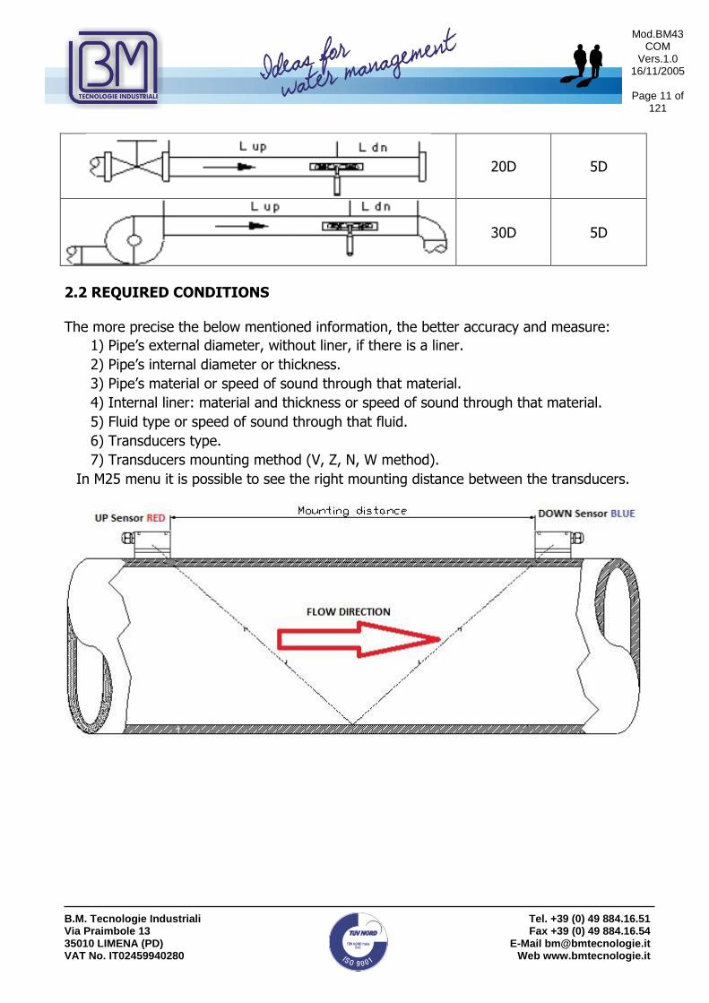
20D 5D
30D 5D
2.2 REQUIRED CONDITIONS The more precise the below mentioned information, the better accuracy and measure:
1) Pipe’s external diameter, without liner, if there is a liner.
2) Pipe’s internal diameter or thickness.
3) Pipe’s material or speed of sound through that material.
4) Internal liner: material and thickness or speed of sound through that material.
5) Fluid type or speed of sound through that fluid.
6) Transducers type.
7) Transducers mounting method (V, Z, N, W method).
In M25 menu it is possible to see the right mounting distance between the transducers.

Mod.BM43 COM
Vers.1.0 16/11/2005
Page 12 of
121
B.M. Tecnologie Industriali Via Praimbole 13 35010 LIMENA (PD) VAT No. IT02459940280
Tel. +39 (0) 49 884.16.51 Fax +39 (0) 49 884.16.54
E-Mail [email protected] Web www.bmtecnologie.it
2.3 A PRACTICAL EXAMPLE OF RAPID SETTINGS
The following example shows an application with a DN 400 carbon steel pipe, no liner, with “V” mounted sensors. IMPORTANT NOTICE: WHEN THE SET-UP IS COMPLETED, THE USER MUST GO BACK TO MENU 26 AND SELECT OPTION 1. SOLIDIFY SETTINGS, AND THEN PRESS ENTER. IN THIS WAY THE PARAMETERS WILL BE SAVED EVEN IF THE POWER SUPPLY GOES OFF.
2.3.1 Fluid & pipe’s features
This is a zinc pipe, so its thickness is not a problem. It is also important to measure the pipe’s circumference: it should be 1286 mm. The pipe is PN10 and it will measure potable water.
2.3.2 Data entry
ATTENTION! The XXXXX values indicated in the following windows are only examples. The value could vary and must not be taken as representative.
Switch on the device and it will display:
Ver . XX.XX
S /N=XXXXXXXX
Then it will display, (it depends from the last switch off) for example:
F l o w 0 . 0 0 0 0 m 3 / h * I
N o S i g n a l D e t e c t e d
The transducers are not installed and their mounting distance will be displayed only after the set-up. Actually the device detects no signals.
Press and the device will display:
F low 0 .0000 m3/h * I
Window No. =
MENU

Mod.BM43 COM
Vers.1.0 16/11/2005
Page 13 of
121
B.M. Tecnologie Industriali Via Praimbole 13 35010 LIMENA (PD) VAT No. IT02459940280
Tel. +39 (0) 49 884.16.51 Fax +39 (0) 49 884.16.54
E-Mail [email protected] Web www.bmtecnologie.it
Press and the device will display window no. 10.
P i p e O u t e r P e r i m e t e r
X X X X m m
Press and :
P i p e O u t e r P e r i m e t e r
1 2 8 6 m m
If you press a wrong digit, press to correct.
Press and the device will display:
P i p e O u t e r D i a m e t e r
X X X . X X X m m
Press and the device will display:
P i p e W a l l T h i c k n e s s
X . X m m
Press , , + and the it will display:
P i p e W a l l T h i c k n e s s
6 . 5 m m
Press and the device will display:
P i p e I n n e r D i a m e t e r
3 9 6 . 3 4 7 m m
The device calculates the value based on the entered settings.
It is possible to press again and the device will display the parameters it calculated until now.
Press and the device will display:
1 0
1 2 8 6 ENT
6 . 5 ENT

Mod.BM43 COM
Vers.1.0 16/11/2005
Page 14 of
121
B.M. Tecnologie Industriali Via Praimbole 13 35010 LIMENA (PD) VAT No. IT02459940280
Tel. +39 (0) 49 884.16.51 Fax +39 (0) 49 884.16.54
E-Mail [email protected] Web www.bmtecnologie.it
P ipe Mate r ia l [14
1 . S ta in less
S tee l
The pipe material depends from the material of the pipe.
Press and “1” and is blinking.
P i p e M a t e r i a l [ 1 4
> 1 . S t a i n l e s s S t e e l
Select the right material by using the
P i p e M a t e r i a l [ 1 4
> 0 . C a r b o n S t e e l
Press ENT and and the device will display:
L i n e r M a t e r i a l [ 1 6
0 . N on e , N o L i n e r
In this case, the pipe has no internal lining, so “0” is correct.
Press and the device will display:
F l u i d T y pe [ 2 0
0 . W a t e r (G e n e r a l )
Press and the device will display:
T r a n s du c e r T y p e [ 2 3
1 6 . C l a m p - on T M 1
NOTE: The standard sensors are Clamp-on TM1 type, for pipes from DN50 up to DN1000. It is possible to ask for different sensors, depending from the application.
ENT

Mod.BM43 COM
Vers.1.0 16/11/2005
Page 15 of
121
B.M. Tecnologie Industriali Via Praimbole 13 35010 LIMENA (PD) VAT No. IT02459940280
Tel. +39 (0) 49 884.16.51 Fax +39 (0) 49 884.16.54
E-Mail [email protected] Web www.bmtecnologie.it
Press and the device will display:
T r a n s du c e r M o u n t i n g
0 . V
Press and the device will display:
T r a n s du c e r S p a c i n g
3 8 5 . 2 6 8 m m
The displayed value id the sensors mounting distance, as shown in par. 2.2. It is possible to install the transducers, as shown in the following par. 2.4.
Press and the device will display:
D e f a u l t s e t t i n g s [ 2 6
1 . S o l i d i f y s e t t i n g s
Press and the device will display:
S a v e / L o a d p a r am e t e r s
> >
Press to go through the parameters:
S a v e / L o a d p a r am e t e r s
> > T o B r o w s e
Or set up one of the 9 (0…8) preset configurations:
S a v e / L o a d p a r am e t e r s
> > E n t r y t o L O A D
Press and the device will display:
S a v e / L o a d p a r am e t e r s
> > E n t r y t o S A V E
Mod.BM43 COM
Vers.1.0 16/11/2005
Page 16 of
121
B.M. Tecnologie Industriali Via Praimbole 13 35010 LIMENA (PD) VAT No. IT02459940280
Tel. +39 (0) 49 884.16.51 Fax +39 (0) 49 884.16.54
E-Mail [email protected] Web www.bmtecnologie.it
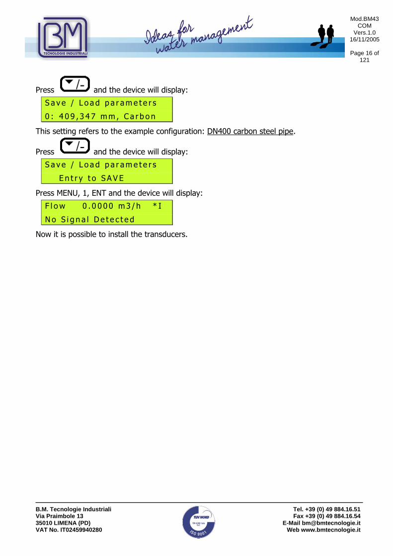
Press and the device will display:
S a v e / L o a d p a r am e t e r s
0 : 4 0 9 , 3 4 7 m m , C a r b o n
This setting refers to the example configuration: DN400 carbon steel pipe.
Press and the device will display:
S a v e / L o a d p a r am e t e r s
E n t r y t o S A V E
Press MENU, 1, ENT and the device will display:
F l o w 0 . 0 0 0 0 m 3 / h * I
N o S i g n a l D e t e c t e d
Now it is possible to install the transducers.

Mod.BM43 COM
Vers.1.0 16/11/2005
Page 17 of
121
B.M. Tecnologie Industriali Via Praimbole 13 35010 LIMENA (PD) VAT No. IT02459940280
Tel. +39 (0) 49 884.16.51 Fax +39 (0) 49 884.16.54
E-Mail [email protected] Web www.bmtecnologie.it
2.4 INSTRUCTIONS FOR CLAMP-ON SENSORS INSTALLATION
If you ordered Clamp-on sensors type TTS100-TS2-NG, TTS100-M1-NG, TTS100-L1-NG, TTS100-S1-NG-HT, TTS100-M1-NG-HT the following instructions are very important for a correct installation of the sensors:
I. In order to install the sensors, check if the pipe has features which could affect the measure, i.e. rust, dirt…
II. Measure the pipes’ diameter by using a callipers

Mod.BM43 COM
Vers.1.0 16/11/2005
Page 18 of
121
B.M. Tecnologie Industriali Via Praimbole 13 35010 LIMENA (PD) VAT No. IT02459940280
Tel. +39 (0) 49 884.16.51 Fax +39 (0) 49 884.16.54
E-Mail [email protected] Web www.bmtecnologie.it
Or, if it is not possible to measure the diameter, please measure the pipe’s circumference:
III. Clean the area where the sensors will be installed by using one of the following tools:
Or

Mod.BM43 COM
Vers.1.0 16/11/2005
Page 19 of
121
B.M. Tecnologie Industriali Via Praimbole 13 35010 LIMENA (PD) VAT No. IT02459940280
Tel. +39 (0) 49 884.16.51 Fax +39 (0) 49 884.16.54
E-Mail [email protected] Web www.bmtecnologie.it
Or

Mod.BM43 COM
Vers.1.0 16/11/2005
Page 20 of
121
B.M. Tecnologie Industriali Via Praimbole 13 35010 LIMENA (PD) VAT No. IT02459940280
Tel. +39 (0) 49 884.16.51 Fax +39 (0) 49 884.16.54
E-Mail [email protected] Web www.bmtecnologie.it
IV. The pipe section where the sensors will be installed should be completely clean:
V. Measure the pipe’s thickness.
This could be done by using our Thickness Gauge TT100-TM8812-NG

Mod.BM43 COM
Vers.1.0 16/11/2005
Page 21 of
121
B.M. Tecnologie Industriali Via Praimbole 13 35010 LIMENA (PD) VAT No. IT02459940280
Tel. +39 (0) 49 884.16.51 Fax +39 (0) 49 884.16.54
E-Mail [email protected] Web www.bmtecnologie.it
Before placing and using the Thickness Gauge sensors, remember to use the coupling grease:
Otherwise, the sensors could loose the grip to the pipe.
VI. Enter the following values into device’s menus:
- pipe’s diameter (MENU 11) or pipe’s circumference (MENU 10)
- pipe’s thickness (MENU 12)
- type of sensors to be used (MENU 23)
- Sensors mounting method (MENU 24)
The device will display the distance at which the sensors should be installed (MENU 25). Now it is possible to start the sensors installation. Please remember to use the coupling grease:
Otherwise, the sensor could loose grip to the pipe.

Mod.BM43 COM
Vers.1.0 16/11/2005
Page 22 of
121
B.M. Tecnologie Industriali Via Praimbole 13 35010 LIMENA (PD) VAT No. IT02459940280
Tel. +39 (0) 49 884.16.51 Fax +39 (0) 49 884.16.54
E-Mail [email protected] Web www.bmtecnologie.it
VII. Sensors could be installed by using a fixing bracket:
Or by using our Rail Guide Mounting System RGMS-TS2-TM1-NG-FIX (only with TS2 & TM1 sensors, pipes form DN15 to DN300).

Mod.BM43 COM
Vers.1.0 16/11/2005
Page 23 of
121
B.M. Tecnologie Industriali Via Praimbole 13 35010 LIMENA (PD) VAT No. IT02459940280
Tel. +39 (0) 49 884.16.51 Fax +39 (0) 49 884.16.54
E-Mail [email protected] Web www.bmtecnologie.it
VIII. Install the sensors according to the distance value the device displays in
MENU 25:
a) Installation of the clamp-on sensors with the fixing brackets:
Installation is completed:

Mod.BM43 COM
Vers.1.0 16/11/2005
Page 24 of
121
B.M. Tecnologie Industriali Via Praimbole 13 35010 LIMENA (PD) VAT No. IT02459940280
Tel. +39 (0) 49 884.16.51 Fax +39 (0) 49 884.16.54
E-Mail [email protected] Web www.bmtecnologie.it
b) Installation of the clamp-on sensors with our Rail Guide Mounting System
RGMS-TS2-TM1-NG-FIX (only with TS2 & TM1 sensors, pipes form DN15 to DN300).
Installation is completed:

Mod.BM43 COM
Vers.1.0 16/11/2005
Page 25 of
121
B.M. Tecnologie Industriali Via Praimbole 13 35010 LIMENA (PD) VAT No. IT02459940280
Tel. +39 (0) 49 884.16.51 Fax +39 (0) 49 884.16.54
E-Mail [email protected] Web www.bmtecnologie.it
2.5 TRANSDUCER MOUNTING METHODS
The transducers mounting positions are related to the pipe diameter and to the type of
sensors. V and Z methods are the most common. By the way, V mounting is suggested.
The other mounting methods are N and W.
The letters V, Z, N, W stands for the number of signal crossings from one transducer to
another.
Z= one crossing. Suitable for pipes > DN250 mm or smaller.
V= two crossings. It is the easiest mounting method for DN600-800 pipes with TL-1
or TM-1 transducers.
N= three crossings. Suitable for small pipes, DN100 or smaller, with TS-2
transducers. It similar to “Z” method, but for small pipes. In this case, the mounting
distance will be bigger.
W= four crossings. Suitable for DN20 pipes with TS-2 transducers. It similar to “V”
method, but for small pipes. In this case, the mounting distance will be bigger.
The following example shows the different mounting solutions.
“Z” mounting method
“V” mounting method
“N” mounting method

Mod.BM43 COM
Vers.1.0 16/11/2005
Page 26 of
121
B.M. Tecnologie Industriali Via Praimbole 13 35010 LIMENA (PD) VAT No. IT02459940280
Tel. +39 (0) 49 884.16.51 Fax +39 (0) 49 884.16.54
E-Mail [email protected] Web www.bmtecnologie.it
“W” mounting method
“W” mounting method
V mounting method is the most common. It can be applied to almost all the applications: it
is the most simple and rapid one.
Z mounting method is suggested only if the signal strength, UP and DOWN (DN) is smaller
than 60 and Q value is smaller than 60, see MENU “90”.

Mod.BM43 COM
Vers.1.0 16/11/2005
Page 27 of
121
B.M. Tecnologie Industriali Via Praimbole 13 35010 LIMENA (PD) VAT No. IT02459940280
Tel. +39 (0) 49 884.16.51 Fax +39 (0) 49 884.16.54
E-Mail [email protected] Web www.bmtecnologie.it
St renth+Qua l i t y [90
UP:54 .4 DN:56 .5
Q=45
2.5.1 “V” mounting method
The “V” method the bounce of the ultrasonic signal inside the pipe. This increases the
distance crosses by the ultrasonic wave. The measuring principle is based on the time
difference and through a “V” distance, the time needed is bigger and the precision higher.
In case of horizontal mounting, it is suggested to avoid the sensors mounting on the top or
on the bottom of the pipe. Air bubbles on the top of the pipe could stop the ultrasonic
wave and deposits on the bottom decrease and change the ultrasonic beam angle.
Refer to the picture below.
In case of vertical mounting, avoid installing the transducers on downward pipe walls, even if they are under pressure. The pipes with an external liner such as tar, polyethylene, epoxy, should be cleaned when in contact with the transducers. A tube for acoustic coupling gel for sensors installation, is included in the supply.

Mod.BM43 COM
Vers.1.0 16/11/2005
Page 28 of
121
B.M. Tecnologie Industriali Via Praimbole 13 35010 LIMENA (PD) VAT No. IT02459940280
Tel. +39 (0) 49 884.16.51 Fax +39 (0) 49 884.16.54
E-Mail [email protected] Web www.bmtecnologie.it
Use a small quantity of coupling grease in order to improve acoustic the contact between the sensor and the pipe’s external surface.
2.5.2 “Z” mounting method
Press 1 while in menu 24 , if you want to choose “Z” mounting.
M 2 4
T r a n s du c e r M o u n t i n g
0 . V - M e t h o d
= > 1 . Z - M e t h o d
Press and the device will display:
M 2 5
T r a n s du c e r S p a c i n g
1 5 2 . 7 7 1 m m
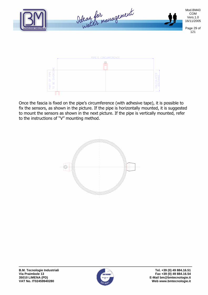
“Z” mounting method is more complicated than “V” mounting method: it is necessary to create a band of foil as long as the pipe circumference and as wide as indicated in MENU 25. Additionally, add a piece of paper to wrap the pipe. Please refer to the picture below for finding the two lines needed to trace the exact half point of the pipe.
Mod.BM43 COM
Vers.1.0 16/11/2005
Page 29 of
121
B.M. Tecnologie Industriali Via Praimbole 13 35010 LIMENA (PD) VAT No. IT02459940280
Tel. +39 (0) 49 884.16.51 Fax +39 (0) 49 884.16.54
E-Mail [email protected] Web www.bmtecnologie.it
Once the fascia is fixed on the pipe’s circumference (with adhesive tape), it is possible to fix the sensors, as shown in the picture. If the pipe is horizontally mounted, it is suggested to mount the sensors as shown in the next picture. If the pipe is vertically mounted, refer to the instructions of “V” mounting method.

Mod.BM43 COM
Vers.1.0 16/11/2005
Page 30 of
121
B.M. Tecnologie Industriali Via Praimbole 13 35010 LIMENA (PD) VAT No. IT02459940280
Tel. +39 (0) 49 884.16.51 Fax +39 (0) 49 884.16.54
E-Mail [email protected] Web www.bmtecnologie.it
2.5.3 “W” & “N” Mounting Methods These methods are suitable for small pipes, DN100 or less, with TS-2 transducers. The signal path consists of four crossings (for “W” method) and three crossings (for “N” method) inside the pipe. These methods are used to increase the transit time and receiving time, otherwise the signal path in small pipes will be too short. In “W” method, the sensors are placed on the same side of the pipe at a definite distance, in “N” method; they are placed on the opposite sides of the pipe, at a definite distance. These methods are not very used because small sensors TS-2 could be installed by using “Z” method. To choose “N” method, press 2 while in menu 24.
M 2 4
T r a n s du c e r M o u n t i n g
0 . V - M e t h o d
1 . Z - M e t h o d
= > 2 . N - M e t h od
Press and the device will display:
M 2 5
T r a n s du c e r S p a c i n g
X X X X X m m
To choose “W” method, press 3 while in menu 24.
M 2 4
T r a n s du c e r M o u n t i n g
0 . V - M e t h o d
1 . Z - M e t h o d
2 . N - M e t h o d
= > 3 . W - M e t h od
Press and the device will display:
M 2 5
T r a n s du c e r S p a c i n g
X X X X X m m

Mod.BM43 COM
Vers.1.0 16/11/2005
Page 31 of
121
B.M. Tecnologie Industriali Via Praimbole 13 35010 LIMENA (PD) VAT No. IT02459940280
Tel. +39 (0) 49 884.16.51 Fax +39 (0) 49 884.16.54
E-Mail [email protected] Web www.bmtecnologie.it
Press and the device will display:
S a v e P a r e m e t e r s [ 2 6
S e l e c t a r o o m
b y E N T U P D N
Save the configuration in one of the 18 rooms available (from 0 to 17) and press
D e f a u l t S e t t i n g [ 2 6
> 1 . S o l i d i f y S e t t i n g
2.5.4 Mounting Analysis
After checking the strength of the received signal, the total spreading time, the time
difference and the rate of spreading time, it is possible to confirm if the installation is
correct.
2.5.5 Signal strength and quality M90
Digit
The strength of signals is displayed by numbers from 00.0 to 99.9.
00.0 means no signal received, 99.9 means max signal. In normal working conditions, the
signal strength should be higher than 60.0.
The signal quality (Q) is displayed by numbers from 00.0 to 99.9. 00.0 means the signal is
the worst. 99.9 mean signal is the best. In normal working conditions, the signal quality
should be higher than 60.0.
During installation, please pay attention to signal strength and quality: they should be at
the maximum level.
M 9 0 0 . 0 0 0 0 %
S t r e n t h + Q u a l i t y
S = 0 0 0 , 0 0 0 Q = 0 0
D e t e c t N o S i g n a l
ENT

Mod.BM43 COM
Vers.1.0 16/11/2005
Page 32 of
121
B.M. Tecnologie Industriali Via Praimbole 13 35010 LIMENA (PD) VAT No. IT02459940280
Tel. +39 (0) 49 884.16.51 Fax +39 (0) 49 884.16.54
E-Mail [email protected] Web www.bmtecnologie.it
2.5.6 Total spreading time, time difference M93
Digit
Tota l T ime,De l ta T ime
623 ,80uS, 242 ,12nS
The measurement method is based on time difference, so the time and other displayed values can identify a correct installation. In normal operating conditions, the time difference should be smaller that ten percent (10%). If the pipe diameter is small or the speed is too low, the difference may be a little higher. If the difference (and also flow and speed) is too high, it means the signal quality is very bad. The reason may be: pipe’s features, wrong installation or wrong parameters setting.
2.5.7 Relation between calculated and measured transit time
To know if the sensors are well mounted, you should calcolate:
TIME – RATE = TOM * 100
TOS
In normal working conditions it should be 100 +/- 3%.
Digit
T O M / T O S * 1 0 0
x x x , x x %
And eventually confirm the right mounting method.
MENU 9 3

Mod.BM43 COM
Vers.1.0 16/11/2005
Page 33 of
121
B.M. Tecnologie Industriali Via Praimbole 13 35010 LIMENA (PD) VAT No. IT02459940280
Tel. +39 (0) 49 884.16.51 Fax +39 (0) 49 884.16.54
E-Mail [email protected] Web www.bmtecnologie.it
3. DISPLAY WINDOWS
This chapter will explain all the display windows of TTFM100 Series and their contents.
The user can enter this menu by pressing
[*][*] represent the number of the window to be displayed. The following list includes all the available windows. 3.1 FLOW RATE- TOTALIZERS MENU
00 All Totalizers
01 Main Display POS Totalizer
02 Main Display NEG Totalizer
03 Main Display NET Totalizer
04 Date Time / Flow Rate + signal
05 Date Time / Signal Velocity
06 Received Shape of Signal
07 Battery Voltage / Battery remaining working time
08 System Error Code + Signal
09 Net Flow Today + Velocity
3.2 INITIAL SETTING MENU
10 Pipe Outer Perimeter
11 Pipe Outer Diameter
12 Pipe Wall Thickness
13 Pipe Inner Diameter
14 Pipe Material
(15 Pipe Sound Velocity) if in menu 14 the user chose “other”
16 Liner Material
(18 Liner Thickness) if in menu 16 the user chose “other”
19 Inside ABS Thickness
20 Fluid Type
(21 Fluid Sound Velocity) if in menu 20 the user chose “other”
(22 Fluid Viscosity) if in menu 20 the user chose “other”
23 Transducer Type
24 Transducer Mounting
25 Transducer Spacing

Mod.BM43 COM
Vers.1.0 16/11/2005
Page 34 of
121
B.M. Tecnologie Industriali Via Praimbole 13 35010 LIMENA (PD) VAT No. IT02459940280
Tel. +39 (0) 49 884.16.51 Fax +39 (0) 49 884.16.54
E-Mail [email protected] Web www.bmtecnologie.it
26 Save Parameters
27 Load Parameters
28 Poor Signal
29 Empty Pipe Set up
3.3 FLOW RATE UNITS MENU
30 Measurement Unit
31 Flow Rate Units
32 Totalize Units
33 Totalize Multiplier
34 NET Totalizer
35 POS Totalizer
36 NEG Totalizer
37 Totalizer Reset
38 Manual Totalizer
39 Language Selection
3.4 OPTIONAL SETTING MENU
40 Damping
41 Low Cutoff Value
42 Set Zero
43 Reset Zero
44 Manual Zero Point
45 Scale Factor
46 Network IDN
47 System Lock
(48 Keypad Lock Code) if in the menu 47 the user chose YES 49 Communication Tester
3.5 INPUTS/ OUTPUTS MENU
50 Logger Option 51 Logger Setup 52 Data Direction 53 Buffer Viewer 54 AI5 Value Range 60 Date and Time 61 Software Version and Serial Number (ESN) 62 RS-232C Setup 67 FO Frequency Range

Mod.BM43 COM
Vers.1.0 16/11/2005
Page 35 of
121
B.M. Tecnologie Industriali Via Praimbole 13 35010 LIMENA (PD) VAT No. IT02459940280
Tel. +39 (0) 49 884.16.51 Fax +39 (0) 49 884.16.54
E-Mail [email protected] Web www.bmtecnologie.it
68 Low FO Flow Rate 69 High FO Flow Rate 70 LCD Backlight Option 71 LCD Contrast 72 Working Timer 73 Alarm #1 Low Value 74 Alarm #1 High Value 75 Alarm #2 Low Value 76 Alarm #2 High Value 77 Buzzer Setup 78 OCT Output Setup 82 Date Totalizer 85 Auto Power Off 86 Auto Control Enabled 87 Power selection 88 RCV Window start 89 RCV Window end
3.6 DIAGNOSTICS MENU
90 Single Strength and Quality
91 TOM / TOS*100
92 Fluid Sound Velocity
93 Total Time and Delta Time
94 Reynolds Number and Factor
3.7 OTHER DISPLAYS MENU
From menu 94 onwards, by pressing
It is possible to display some additional information
M+ 0 Power ON/OFF Time
M+ 1 Total Working Time
M+ 2 Last Power Off
M+ 3 Last Flow Rate
M+ 4 ON/OFF Times
M+ 5 Calculator M+ 6 Velocity change M+ 7 Protocol Select M+ 8 Receive Shape

Mod.BM43 COM
Vers.1.0 16/11/2005
Page 36 of
121
B.M. Tecnologie Industriali Via Praimbole 13 35010 LIMENA (PD) VAT No. IT02459940280
Tel. +39 (0) 49 884.16.51 Fax +39 (0) 49 884.16.54
E-Mail [email protected] Web www.bmtecnologie.it
3.8 FLOW RATE- TOTALIZERS MENU ANALYSIS Digit
and the device will display
P O S + 4 8 7 9 m 3
N E G - 3 3 6 m 3
N E T + 4 5 4 3 m 3
S = 0 0 0 , 0 0 0 Q = 0 0 I
This a display window. The measuring units should be set up in menu M31 and M32. NET is the net totalizer, result of adding the positive totalizer POS to the negative totalizer NEG. Digit
and the device will display
P O S + 4 8 7 9 m 3
F l o w 1 2 3 . 0 0 l / s
V e l 0 . 5 6 7 8 m / s
S = 6 7 9 , 6 8 1 Q = 5 6 R
This a display window. The measuring units should be set up in menu M31 and M32. Digit
and the device will display
N E G - 3 3 6 m 3
F l o w 1 2 3 . 0 0 l / s
V e l 0 . 5 6 7 8 m / s
S = 6 7 9 , 6 8 1 Q = 5 6 R
This a display window. The measuring units should be set up in menu M3. The POS value refers to the positive totalizer. Digit
and the device will display
N E T + 4 5 4 3 m 3
F l o w 1 2 3 . 0 0 l / s
V e l 0 . 5 6 7 8 m / s
S = 6 7 9 , 6 8 1 Q = 5 6 R
This a display window. The measuring units should be set up in menu M31 and M36. The NEG value refers to the negative totalizer.

Mod.BM43 COM
Vers.1.0 16/11/2005
Page 37 of
121
B.M. Tecnologie Industriali Via Praimbole 13 35010 LIMENA (PD) VAT No. IT02459940280
Tel. +39 (0) 49 884.16.51 Fax +39 (0) 49 884.16.54
E-Mail [email protected] Web www.bmtecnologie.it
Digit
and the device will display
D a t e 0 6 - 1 1 - 1 2
T i m e 0 9 : 5 4 : 0 0
F l o w 1 2 3 . 0 0 l / s
S = 6 7 9 , 6 8 1 Q = 5 6 R
This window displays date and time in the following format yy-mm-dd; hh-mm-ss, and the current flow rate. Date and time should be set up in menu M60. Digit
and the device will display
D a t e 0 6 - 1 1 - 1 2
T i m e 0 9 : 5 4 : 0 0
V e l 0 . 5 6 7 8 m / s
S = 6 7 9 , 6 8 1 Q = 5 6 R
This window displays date and time in the following format yy-mm-dd; hh-mm-ss, and the current speed. Date and time should be set up in menu M60. Digit
and the device will display
R C V
S H P _ _ _ _ _ _ _ _ _ _ _
This window displays shape of the signal received by the transducers Digit
and the device will display
B a t t e r y V o l t a g e
3 . 5 6 7 9 V
B a t t e r y W o r k t i m e
0 0 : 4 5 : 3 4
This window displays the battery features and status.

Mod.BM43 COM
Vers.1.0 16/11/2005
Page 38 of
121
B.M. Tecnologie Industriali Via Praimbole 13 35010 LIMENA (PD) VAT No. IT02459940280
Tel. +39 (0) 49 884.16.51 Fax +39 (0) 49 884.16.54
E-Mail [email protected] Web www.bmtecnologie.it
Digit
and the device will display
E r r o r C o d e
- - - - - - - - - - - - - - - - - - - - - - - R
S y s t e m N o r m a l
S = 6 7 9 , 6 8 1 Q = 5 6 R
This window displays the error codes. Please refer to the list of complete error codes at page 65. Digit
and the device will display
N e t F l o w T o d a y
1 3 4 m 3
V e l 0 . 5 6 7 8 m / s
S = 6 7 9 , 6 8 1 Q = 5 6 R
This window displays the net daily flow rate.

Mod.BM43 COM
Vers.1.0 16/11/2005
Page 39 of
121
B.M. Tecnologie Industriali Via Praimbole 13 35010 LIMENA (PD) VAT No. IT02459940280
Tel. +39 (0) 49 884.16.51 Fax +39 (0) 49 884.16.54
E-Mail [email protected] Web www.bmtecnologie.it
3.9 INITIAL SETTING MENU ANALYSIS Digit
and the device will display
M 1 0
O u t e r P e r i m e t e r
1 2 8 6 m m
This window is used to set up the pipe’s perimeter, if known or measurable. Digit
and the device will display
M 1 1
O u t e r D i a m e t e r
4 0 9 . 3 4 7 m m
This window is used to set up the external pipe’s diameter. When the pipe’s external perimeter diameter is set up, the external pip’s diameter is automatically setup too. Digit
and the device will display
M 1 2
W a l l T h i c k n e s s
6 . 5 m m
This window is used to set up the pipe’s thickness. It is also possible to pass over this menu and go to the menu M13, used to set up the internal pipe’s diameter. Digit
and the device will display
M 1 3
I n n e r D i a m e t e r
3 9 6 , 3 4 7 m m
This window is used to set up the net pipe’s internal diameter. Digit
and the device will display
M 1 4
P i p e M a t e r i a l
0 . C a r b on S t e e l
This window is used to set up the pipe’s material. Press ENTER to activate the material selection. Use the arrow keys to scroll among the list:

Mod.BM43 COM
Vers.1.0 16/11/2005
Page 40 of
121
B.M. Tecnologie Industriali Via Praimbole 13 35010 LIMENA (PD) VAT No. IT02459940280
Tel. +39 (0) 49 884.16.51 Fax +39 (0) 49 884.16.54
E-Mail [email protected] Web www.bmtecnologie.it
0 Carbon Steel 1 Stainless Steel 2 Cast Iron 3 Ductile Iron 4 Copper 5 PVC 6 Aluminium 7 Asbestos 8 Fibreglass 9 Other If option 9 is chosen, it is necessary to set up the sound speed, see the APPENDIX, from page 70. This window will de displayed only if in M14 the user chose “9. OTHER” Digit
and the device will display
M 1 5
P i p e S ou n d V e l
x x x x m / s
Set up the speed of sound through the pipe material, referring to the construction material of the pipe.
For information about the sound speed through other types of materials that are not included in the list, please refer to the tables starting at page 70.
Digit
and the device will display
M 1 6
L i n e r M a t e r i a l
0 . N o L i n e r
This window is used to set up the liner’s material. Press ENTER to activate the material selection. Use the arrow keys to scroll among the list: 0 NO Liner 1 Tar Epoxy 2 Rubber
3 Mortar 4 Polypropylene 5 Polystyrol 6 Polystryene

Mod.BM43 COM
Vers.1.0 16/11/2005
Page 41 of
121
B.M. Tecnologie Industriali Via Praimbole 13 35010 LIMENA (PD) VAT No. IT02459940280
Tel. +39 (0) 49 884.16.51 Fax +39 (0) 49 884.16.54
E-Mail [email protected] Web www.bmtecnologie.it
7 Polyester 8 Polyethylene 9 Ebonite 10 Teflon 11 Other
If option 11 is chosen, it is necessary to set up the sound speed, see the APPENDIX, from page 70. This window will de displayed only if in M16 the user chose “11. OTHER” Digit
and the device will display
M 1 7
L i n e r S ou n d V e l o c i t y
x x x x m / s
Set up the spreading time of sound through the construction material of the liner. For information about the sound speed through other types of materials that are not included in the list, please refer to the tables starting at page 70. This window will de displayed only if in M16 the user chose “11. OTHER” Digit
and the device will display
M 1 8
L i n e r T h i c k n e s s
0 m m
Set up the internal liner thickness.
Digit
and the device will display
I n s i d e A B S Th i c k n e s s [ 1 8
0 m m
This menu is not used, please ingnore it. Digit
and the device will display
M 2 0
F l u i d T y pe
0 W a t e r
This window is used to set up the measuring flow type.
MENU 1 9

Mod.BM43 COM
Vers.1.0 16/11/2005
Page 42 of
121
B.M. Tecnologie Industriali Via Praimbole 13 35010 LIMENA (PD) VAT No. IT02459940280
Tel. +39 (0) 49 884.16.51 Fax +39 (0) 49 884.16.54
E-Mail [email protected] Web www.bmtecnologie.it
Press ENT to enable the fluid selection and use the arrow keys to scroll the list: 0 Water 1 Sea Water 2 Kerosene 3 Gasoline 4 Fuel Oil 5 Crude Oil 6 Propane (-45°C) 7 Butane (0°C) 8 Other 9 Diesel Oil 10 Castor Oil 11 Peanut Oil 12 Gasoline #90 13 Gasoline #93 14 Alcohol 15 Water (+125°C)
Press ENT to confirm. This window will de displayed only if in M20 the user chose “8. OTHER” Digit
and the device will display
M 2 1
F l u i d S ou n d V e l o c i t y
1 4 8 2 . 8 m / s
Enter speed of sound through the fluid to be measured. For information about the sound speed through other types of materials that are not included in the list, please refer to the tables starting at page 70. This window will de displayed only if in M20 the user chose “8. OTHER” Digit
and the device will display
M 2 2
F l u i d V i s c o s i t y
1 . 0 0 3 8 c S T
Enter the viscosity of the fluid to be measured.

Mod.BM43 COM
Vers.1.0 16/11/2005
Page 43 of
121
B.M. Tecnologie Industriali Via Praimbole 13 35010 LIMENA (PD) VAT No. IT02459940280
Tel. +39 (0) 49 884.16.51 Fax +39 (0) 49 884.16.54
E-Mail [email protected] Web www.bmtecnologie.it
Digit
and the device will display
T r a n s du c e r T y p e [ 2 3
0 . C l a m p - on T M - 1
This window is used to set up the type of transducers. Press ENT to enable the transducers type selection and use the arrow keys to scroll the list:
0. Standard M 1. Plug-in type A 2. Clamp-on TM-1 * 3. User Type 4. Standard B 5. Plug-in Type B45 6. Standard L 7. Clamp-on TS-2 * 8. Standard M1 9. Plug-in Type C 10. Standard HS 11. Standard HM 12. Standard S1 13. PI-Pipe 14. Standard L1 15.Clamp-on TL-1 *
* OUR STANDARD CLAMP-ON SENSORS Press ENT to confirm the type of transducers. Selection No. 3 “USER TYPE” allows the user to install types of sensors not included in the list. In this case, it is necessary to enter some more information about the technical features of the new type of sensors: 1. wedge degree of ultrasonic impulse.
P i - P i p e P a r am e t e r
W e d ge D e g r e e
4 5 d e g
2. speed of sound.

Mod.BM43 COM
Vers.1.0 16/11/2005
Page 44 of
121
B.M. Tecnologie Industriali Via Praimbole 13 35010 LIMENA (PD) VAT No. IT02459940280
Tel. +39 (0) 49 884.16.51 Fax +39 (0) 49 884.16.54
E-Mail [email protected] Web www.bmtecnologie.it
P i - P i p e P a r am e t e r
W e d ge S ou n d V e l o c i t y
2 7 2 0 m / s
3. distance from crystal to sensor wedge.
P i - P i p e P a r am e t e r
W e d ge D i s t a n c e
3 2 m m
4. delay of ultrasonic signal.
P i - P i p e P a r am e t e r
W e d ge T i m e D e l a y
5 . 1 8 u S
Digit
and the device will display
M 2 4
T x d u c e r M o u n t i n g
0 . V - M e t h o d
This window is used to set up the mounting method of the transducers. Press ENT to enable the transducers type selection and use the arrow keys to scroll the list:
0. V Method 1. Z Method 2. N Method (small pipes) 3. W Method (small pipe)
Press ENT to confirm the type of transducers. Digit
and the device will display
M 2 5
T r a n s du c e r S p a c i n g
3 8 5 . 2 6 8 m m
This window informs about the mounting distance of the transducers. See. Par. 2.4-2.5.

Mod.BM43 COM
Vers.1.0 16/11/2005
Page 45 of
121
B.M. Tecnologie Industriali Via Praimbole 13 35010 LIMENA (PD) VAT No. IT02459940280
Tel. +39 (0) 49 884.16.51 Fax +39 (0) 49 884.16.54
E-Mail [email protected] Web www.bmtecnologie.it
Digit
and the device will display
M 2 6
S a v e P a r a m e t e r s
S e l e c t a r o o m
b y E N T U P D N
This windows allows the user to save the configuration. It is possible to save up to 18 configurations (from 0 to 17). Digit
and the device will display
M 2 7
L o a d P a r a m e t e r s
S e l e c t a r o o m
b y E N T U P D N
This window is used to upload one of the 18 saved configurations. Press ENT and then use the arrow keys to scroll among the configurations. Press ENT to select the desired one. Digit
and the device will display
M 2 8
H o l d i n g P o o r S i g n a l
Y E S
This window is used to set up the device in order to maintain the last reading as valid in case of temporary loss of signal. If NO is selected, output signal could be modified. Digit
and the device will display
M 2 9
E m p t y P i p e S e t u p
0
This window is used to set up a min threshold. Below that threshold the device considers the pipe as empty. Set up a value among 30 and 40 in order to be sure the device does not measure when the pipe is empty.

Mod.BM43 COM
Vers.1.0 16/11/2005
Page 46 of
121
B.M. Tecnologie Industriali Via Praimbole 13 35010 LIMENA (PD) VAT No. IT02459940280
Tel. +39 (0) 49 884.16.51 Fax +39 (0) 49 884.16.54
E-Mail [email protected] Web www.bmtecnologie.it
3.10 FLOW RATE UNITS MENU ANALYSIS Digit
and it will display
M 3 0
M e a s u r e m e n t U n i t s
M e t r i c
This window is used to set up the measuring system: 0. metric 1. English
Press ENT and then use the arrow keys to choose the measuring system. Confirm with ENT. Digit
and the it will display
M 3 1
F l o w R a t e U n i t s
m 3 / h
This window is used to set up the measuring flow rate units. Press ENT and then use the arrow keys to select the measuring unit among:
0. Cubic Meters 1. Litres 2. USA Gallons 3. Imperial Gallons 4. USA Million Gallons 5. Cubic Feet (cf) 6. USA Barrels 7. Imperial Barrels 8. Oil Barrels (ob)
Press ENT to confirm the selection and it will display:
M 3 1
C u b i c M e t e r s (m 3 )
: : / h o u r
/ d a y
Use the arrow keys to select the time units to which the current flow rate should refer: /hour /day /min /sec

Mod.BM43 COM
Vers.1.0 16/11/2005
Page 47 of
121
B.M. Tecnologie Industriali Via Praimbole 13 35010 LIMENA (PD) VAT No. IT02459940280
Tel. +39 (0) 49 884.16.51 Fax +39 (0) 49 884.16.54
E-Mail [email protected] Web www.bmtecnologie.it
Press ENT to confirm the selection. Digit
and the it will display
M 3 2
T o t a l i z e r U n i t s
C u b i c M e t e r s
This window is used to set up totalizing flow rate units, please refer to menu M31 for what concerns Volumetric units and their setting. Factory settings are in m3. Press ENT and then use the arrow keys to select the measuring unit among:
0. Cubic Meters 1. Litres 2. USA Gallons 3. Imperial Gallons 4. USA Million Gallons 5. Cubic Feet (ct) 6. USA Barrels 7. Imperial Barrels 8. Oil Barrels (ob)
Digit
and the it will display
M 3 3
T o t a l i z e r M u l t i p l i e r
X 1
This window is used to set up the multiplying factor for totalization, in order to avoid reaching the max. counting in a short time. Press ENT and then use the arrow keys to select among:
0. X 0.001 (1E-3) 1. X 0.01 2. X 0.1 3. X1 4. X10 5. X100 6. X1000 7. X10000 (1E+4)
Press ENT to confirm.

Mod.BM43 COM
Vers.1.0 16/11/2005
Page 48 of
121
B.M. Tecnologie Industriali Via Praimbole 13 35010 LIMENA (PD) VAT No. IT02459940280
Tel. +39 (0) 49 884.16.51 Fax +39 (0) 49 884.16.54
E-Mail [email protected] Web www.bmtecnologie.it
Digit
and the it will display
M 3 4
N E T T o t a l i z e r
O N
This window is used to enable the net totalizer, between positive and negative totalizers. Factory setting is ON. Press ENT and then use the arrow keys to select ON or OFF. Press ENT to confirm. Digit
and the it will display
M 3 5
P O S T o t a l i z e r
O N
This windows is used to enable the positive totalizer. Factory setting is ON. Press ENT and then use the arrow keys to select ON or OFF. Press ENT to confirm. Digit
and the it will display
M 3 6
N E G T o t a l i z e r
O N
This windows is used to enable the negative totalizer. Factory setting is ON. Press ENT and then use the arrow keys to select ON or OFF. Press ENT to confirm. Digit
and the it will display
M 3 7
T o t a l i z e r R e s e t ?
S e l e c t i o n
This window is used to enable the complete or selective reset of internal counters. Press ENT and then use the arrow keys to select NO or YES. If YES is chosen, please select among: None All NET TOtalizer POS Totalizet NEG Totalizer

Mod.BM43 COM
Vers.1.0 16/11/2005
Page 49 of
121
B.M. Tecnologie Industriali Via Praimbole 13 35010 LIMENA (PD) VAT No. IT02459940280
Tel. +39 (0) 49 884.16.51 Fax +39 (0) 49 884.16.54
E-Mail [email protected] Web www.bmtecnologie.it
Press ENT to confirm the selection and the device will display:
M 3 7
S e l e c t T o t a l i z e r
R e s e t F i n i s h e d
Digit
and the it will display
M 3 8
M a n u a l T o t a l i z e r
E N T W h e n R e a d y
This window is used to enable the totalizer backlog. Press ENT to enable the backlog (ON), press ENT again to disable the backlog (OFF). Digit
and the it will display
M 3 9
L a n gu a g e
E n g l i s h
This window is used to select the device’s display language. Press ENT and then use the arrow keys to select the language. Press ENT to confirm. Digit
and the it will display
M 4 0
D a m p i n g
1 5 s e c
This window allows the user to change the value of damping, the seconds needed to display the analog signals and the output signals. The standard value is between 15 and 30 seconds, the setting range goes from 0 to 99 seconds. Digit
and the it will display
M 4 1
L o w F l o w C u t o f f V a l .
0 . 0 3 m / s
This window allows the user to set up the speed threshold. Below that level, the device will display 0 flow rate and the totalization is stopped.

Mod.BM43 COM
Vers.1.0 16/11/2005
Page 50 of
121
B.M. Tecnologie Industriali Via Praimbole 13 35010 LIMENA (PD) VAT No. IT02459940280
Tel. +39 (0) 49 884.16.51 Fax +39 (0) 49 884.16.54
E-Mail [email protected] Web www.bmtecnologie.it
Digit
and the it will display
M 4 2
S e t Z e r o
P r e s s E N T t o g o
This windows is used to enable the flow rate zero procedure with a static fluid. The flow into the pipe must be completely static. The zero procedure has beneficial effects both in low and high flow rate. Press ENT and the device will display an indicator going right to “0”. it will be possible to delete the zero setting by using the next menu 43.
Warning!!!
If the flow rate is different from 0, the displayed current flow rate will be 0.
Digit
and the it will display
M 4 3
R e s e t Z e r o
N O
This window is used to delete the zero procedure of the previous menu M42. press ENT and then use the arrow keys to display NO or YES, to disable or enable the deleting function. Digit
and the it will display
M 4 4
M a n u a l Z e r o P o i n t
0 m 3 / h
This window is used for setting an offset value to be added or detracted (it depends from the setting polarity) to the current flow rate. Usually, if the user knows very well the current flow rate, this function permits to correct the displayed value. Press ENT and then the arrow keys in order to have a negative offset value, followed by the valued to be added or detracted. Press ENT again to confirm. Digit
and the it will display
M 4 5
S c a l e F a c t o r
1
This window is used to set up the scale factor value. This value will affect the measure in order to correct the displayed value.

Mod.BM43 COM
Vers.1.0 16/11/2005
Page 51 of
121
B.M. Tecnologie Industriali Via Praimbole 13 35010 LIMENA (PD) VAT No. IT02459940280
Tel. +39 (0) 49 884.16.51 Fax +39 (0) 49 884.16.54
E-Mail [email protected] Web www.bmtecnologie.it
Digit
and the it will display
M 4 6
N e t w o r k ID N
8 8
This window is used to set up the ID value of the net. The values could be set among 0 and 65535 except for 13(0DH enter), 10(0AH enter), 42(2AH*), 38(26H&), 65535. The ID value is used during the setting operations to identify the device in a devices network. Digit
and the it will display
M 4 7
S y s t e m L o c k
* * * * U n l o c k e d * * * *
This windows is used to set up a password to block the system from unauthorized access. It is composed of a number from 1 up to 4 digits. Digit
and the it will display
M 4 9
C o m m Te s t e r
This window is used to display the communication test with a remote device by serial port.
MENU 4 9

Mod.BM43 COM
Vers.1.0 16/11/2005
Page 52 of
121
B.M. Tecnologie Industriali Via Praimbole 13 35010 LIMENA (PD) VAT No. IT02459940280
Tel. +39 (0) 49 884.16.51 Fax +39 (0) 49 884.16.54
E-Mail [email protected] Web www.bmtecnologie.it
3.11 INPUTS/ OUTPUTS MENU ANALYSIS Digit
and the it will display
M 5 0
L o g g e r O p t i o n
O N
This window is used to enable the data logging by using an external logger. Press ENT and then use the arrow keys to enable or disable the parameter to be logged. If ON is chosen, it will be possible to choose among:
1. Date Time ON / OFF 2. System Status ON / OFF 3. Current Window ON / OFF 4. Flow Rate ON / OFF 5. Velocity ON / OFF 6. NET Totalizer ON / OFF 7. POS Totalizer ON / OFF 8. NEG Totalizer ON / OFF 9. Signal Strength ON / OFF 10. Working Timer ON / OFF 11. Flow Today ON / OFF
Press ENT and then use the arrow keys to select the desired parameter to be enable/disabled. Digit
and the it will display
M 5 1 L o gg e r S e t u p
S t a r t T i m e 0 0 : 0 0 : 0 0
I n t e r v a l 0 0 : 0 0 : 0 0
G o O n T i m e 0 0 : 0 0 : 0 0
This window is used to set up the data logging time. It should be set to go on until a definite time set by the user.

Mod.BM43 COM
Vers.1.0 16/11/2005
Page 53 of
121
B.M. Tecnologie Industriali Via Praimbole 13 35010 LIMENA (PD) VAT No. IT02459940280
Tel. +39 (0) 49 884.16.51 Fax +39 (0) 49 884.16.54
E-Mail [email protected] Web www.bmtecnologie.it
Digit
and the it will display
M 5 2
D a t a D i r e c t i o n
0 . T o R S - 2 3 2
This window is used to set the direction of the data the device is logging. It is possible to select an ption among:
0. To RS232 1. To Buffer 2. Buffer=>RS232 3. Clear Buffer
Select the option and confirm with ENT. Digit
and the it will display
M 5 3
B u f f e r V i e w e r
P r e s s E N T t o g o
This window is related to the editing of the internal buffer’s data. Menus from M54 to M59 are not used. They will be implemented in next software versions. Digit
and the device will display
M 6 0
D a t e Y Y – M M – D D
T i m e H H : M M :S S
This window is used to set up date and time. Press ENT and digit: year, month, day of the month, hour, minute and seconds. Press ENT again to confirm. If during the set-up the
user makes a mistake, or if it is necessary to change a value, press the key until you reach the desired digit and the digit the right number.

Mod.BM43 COM
Vers.1.0 16/11/2005
Page 54 of
121
B.M. Tecnologie Industriali Via Praimbole 13 35010 LIMENA (PD) VAT No. IT02459940280
Tel. +39 (0) 49 884.16.51 Fax +39 (0) 49 884.16.54
E-Mail [email protected] Web www.bmtecnologie.it
Digit
and the device will display
M 6 1
V e r 8 . 3 8 x 3 2
E S N = 0 6 0 8 0 2 6 2 H
This window displays the software version and the serial number of the device (ESN). Due to continuous software updating, the software versions could be different. Digit
and the device will display
M 6 2
R S - 2 3 2 C S e t u p
B a u d r a t e : = 1 9 2 0 0 ,
P a r i t y : N o n e
This window is used to set up the communication parameters of the serial port. Press ENT and then use the arrow keys to select among: Baud Rate:
115200 57600 38400 14400 28800 19200 9600 4800 3600 2400 1200 600 300 150 110 75
Press ENT to confirm the selected option and then select the parity type among:
None Even Odd
Press ENT to confirm the selection and exit the setting. The other parameters are factory set up: 8 bit data, 1 bit stop and flow control Xon/Xoff.

Mod.BM43 COM
Vers.1.0 16/11/2005
Page 55 of
121
B.M. Tecnologie Industriali Via Praimbole 13 35010 LIMENA (PD) VAT No. IT02459940280
Tel. +39 (0) 49 884.16.51 Fax +39 (0) 49 884.16.54
E-Mail [email protected] Web www.bmtecnologie.it
Menus from M63 to M66 are not used. They will be implemented in next software versions. Digit
and the device will display
M 6 7
F O F r e qu e n c y R an g e
0 – 9 9 9 9
This window is used to set up the frequence output in the field 0-9999 Hz, proportionally to the measured flow rate: Press ENT and then the ↓ key. the device will display:
M 6 8
L o w F O F l o w R a t e
0 m 3 / h
Digit the starting range value and press ENT, then press the ↓ key and the device will
display:
M 6 9
H i g h F O F l ow R a t e
1 5 0
m 3 / h
Digit the ending range value and press the ↓ key. The setting is finished.
Digit
and the device will display
M 7 0
L C D B a c k l i g h t
This window is used to set up the display backlight mode. Digit
and the device will display
M 7 1
L C D C o n t r a s t
8
This window is used to set up the display contrast. Press ENT and the use the arrow keys to select a value from 0 up to 31. Press ENT again to confirm the selection.

Mod.BM43 COM
Vers.1.0 16/11/2005
Page 56 of
121
B.M. Tecnologie Industriali Via Praimbole 13 35010 LIMENA (PD) VAT No. IT02459940280
Tel. +39 (0) 49 884.16.51 Fax +39 (0) 49 884.16.54
E-Mail [email protected] Web www.bmtecnologie.it
Digit
and the device will display
M 7 2
W o r k i n g T i m e r
3 4 : 5 4 : 3 2
This window displays the device working time. Press ENT and then use the arrow keys to delete the device working time. Press ENT to confirm the selection. Digit
and the device will display
M 7 3
A l a r m # 1 L o w V a l u e
0 m 3 / h
This window is used to set up the min. flow rate threshold for alarm 1. press ENT, digit the flow rate value and press ENT again. Digit
and the device will display
M 7 4
A l a r m # 1 H i g h V a l u e
5 0 0 3 / h
This window is used to set up the max. flow rate threshold for alarm 1. press ENT, digit the flow rate value and press ENT again. Digit
and the device will display
M 7 5
A l a r m # 2 L o w V a l u e
0 m 3 / h
This window is used to set up the min. flow rate threshold for alarm 2. press ENT, digit the flow rate value and press ENT again. Digit
and the device will display
M 7 6
A l a r m # 2 H i g h V a l u e
5 0 0 3 / h
This window is used to set up the max. flow rate threshold for alarm 1. press ENT, digit the flow rate value and press ENT again.

Mod.BM43 COM
Vers.1.0 16/11/2005
Page 57 of
121
B.M. Tecnologie Industriali Via Praimbole 13 35010 LIMENA (PD) VAT No. IT02459940280
Tel. +39 (0) 49 884.16.51 Fax +39 (0) 49 884.16.54
E-Mail [email protected] Web www.bmtecnologie.it
Digit
and the device will display
M 7 7
B U Z Z E R S e t u p
1 6 . N o t U s i n g
This window is used to set up up the buzzer. Press ENT and then use the arrow keys to select among:
No signal Poor signal Not ready Reverse flow A.O. Over 100% F.O. Over 120% Alarm #1 Alarm #2 Batch control POS Int Pulse NEG Int Pulse NET Int Pulse No function ON/OFF via RS232 Fluid changed Key stroke ON Not using
Press ENT again to confirm the selection. Digit
and the device will display
M 7 8
O C T O u t p u t S e t u p
1 3 . F O
This window is used to set up the open collector function (OCT). Press ENT and then use the arrow keys to select among these options:
No signal Poor signal Not ready Reverse flow A.O. Over 100% F.O. Over 120% Alarm #1 Alarm #2

Mod.BM43 COM
Vers.1.0 16/11/2005
Page 58 of
121
B.M. Tecnologie Industriali Via Praimbole 13 35010 LIMENA (PD) VAT No. IT02459940280
Tel. +39 (0) 49 884.16.51 Fax +39 (0) 49 884.16.54
E-Mail [email protected] Web www.bmtecnologie.it
Batch control POS Int Pulse NEG Int Pulse NET Int Pulse Energy Pulse FO FO via RS232C ON/OFF via RS232 Fluid changed Not using
Press ENT again to confirm the selection. Menus from M79 to M81 are not used. They will be implemented in next software versions. Digit
and the device will display
M 8 2
D a t e T o t a l i z e r
V i e w b y D ay
This window is used to set up the time for logging the flow rate volume. Press ENT and then use the arrow keys to select one option among the following: View by Day View by Month View by Year Press ENT again to confirm the selection and activate the displaying of the following:
N o . 0 0
D a t e 0 6 - 1 1 - 1 2
S t a t u s - - - - - - - - - R
3 4 5 6 . 9 5 m 3
The first line display the logging “00” dated 11th of August 2006, other information are related to the current errors, the other line displays the flow rate on the 11th of August 2006 at 23:59:59. press the ↑ key to scroll the other 63 loggings. Press ENT to exit this
display. Menus M83 and M84 are not used. They will be implemented in next software versions.

Mod.BM43 COM
Vers.1.0 16/11/2005
Page 59 of
121
B.M. Tecnologie Industriali Via Praimbole 13 35010 LIMENA (PD) VAT No. IT02459940280
Tel. +39 (0) 49 884.16.51 Fax +39 (0) 49 884.16.54
E-Mail [email protected] Web www.bmtecnologie.it
Digit
and the device will display
M 8 5
A u t o P o w e r O f f
E n a b l e
D i s a b l e
This menu allows the user to enable or disable the automatic power off. Select between the two options and press ENT to confirm.
WARNING!!! THE FOLLOWING MENU 86, 87, 88, 89 HAVE BEEN CREATED FOR VERY EXPERT USERS. B.M. TECNOLOGIE INDUSTRIALI SUGGESTS NOT TO CHANGE THEM. PLS LEAVE THE FOLLOWING MENUS AS DEFAULT SET. Digit
and the device will display
M 8 6
A u t o C N T R E n a b l e
Y E S
This menu allows the user to select between automatic or user defined status. Automatic is the default status. User defined status is used to define peculiar conditions in which the control parameters set by the customer are activated. We suggest not to change this menu. Leave it as factory default. If needed, select between the two options and press ENT to confirm. Digit
and the device will display
M 8 7
P o w e r S e l e c t i o n
This menu allows the user to select how many pulses will be sent out to activate the transducers. The selection could be done among 1…10 pulses. Default setting: 10 pulses. We suggest not to change this menu. Leave it as factory default. If needed, select between the options and press ENT to confirm.

Mod.BM43 COM
Vers.1.0 16/11/2005
Page 60 of
121
B.M. Tecnologie Industriali Via Praimbole 13 35010 LIMENA (PD) VAT No. IT02459940280
Tel. +39 (0) 49 884.16.51 Fax +39 (0) 49 884.16.54
E-Mail [email protected] Web www.bmtecnologie.it
Menus M88 and M89 will be operative only if in menu M86, the user selected NO (not default setting). As we recommend not to change M86 settings, the following menus will not be used. Digit
and the device will display
M 8 8
R C V W i n d o w S t a r t
8 0
This menu allows the user to enter the starting time of the receiving signal window. Signals arriving before the starting time will be neglected by the device. We suggest not to change this menu. Leave it as factory default. If needed, select between the options and press ENT to confirm. Digit
and the device will display
M 8 9
R C V W i n d o w E n d
1 2 5
This menu allows the user to enter the ending time of the receiving signal window. Signals arriving after the ending time will be neglected by the device. We suggest not to change this menu. Leave it as factory default. If needed, select between the options and press ENT to confirm.
Mod.BM43 COM
Vers.1.0 16/11/2005
Page 61 of
121
B.M. Tecnologie Industriali Via Praimbole 13 35010 LIMENA (PD) VAT No. IT02459940280
Tel. +39 (0) 49 884.16.51 Fax +39 (0) 49 884.16.54
E-Mail [email protected] Web www.bmtecnologie.it
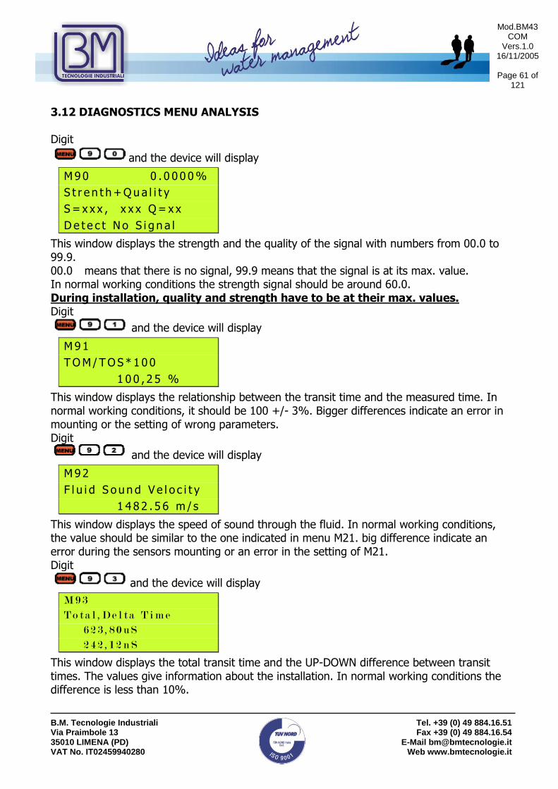
3.12 DIAGNOSTICS MENU ANALYSIS Digit
and the device will display
M 9 0 0 . 0 0 0 0 %
S t r e n t h + Q u a l i t y
S = x x x , x x x Q = x x
D e t e c t N o S i g n a l
This window displays the strength and the quality of the signal with numbers from 00.0 to 99.9. 00.0 means that there is no signal, 99.9 means that the signal is at its max. value. In normal working conditions the strength signal should be around 60.0. During installation, quality and strength have to be at their max. values. Digit
and the device will display
M 9 1
T O M / T O S * 1 0 0
1 0 0 , 2 5 %
This window displays the relationship between the transit time and the measured time. In normal working conditions, it should be 100 +/- 3%. Bigger differences indicate an error in mounting or the setting of wrong parameters. Digit
and the device will display
M 9 2
F l u i d S ou n d V e l o c i t y
1 4 8 2 . 5 6 m / s
This window displays the speed of sound through the fluid. In normal working conditions, the value should be similar to the one indicated in menu M21. big difference indicate an error during the sensors mounting or an error in the setting of M21. Digit
and the device will display
M 9 3
T o t a l , D e l t a T i m e
6 2 3 , 8 0 u S
2 4 2 , 1 2 n S
This window displays the total transit time and the UP-DOWN difference between transit times. The values give information about the installation. In normal working conditions the difference is less than 10%.
Mod.BM43 COM
Vers.1.0 16/11/2005
Page 62 of
121
B.M. Tecnologie Industriali Via Praimbole 13 35010 LIMENA (PD) VAT No. IT02459940280
Tel. +39 (0) 49 884.16.51 Fax +39 (0) 49 884.16.54
E-Mail [email protected] Web www.bmtecnologie.it
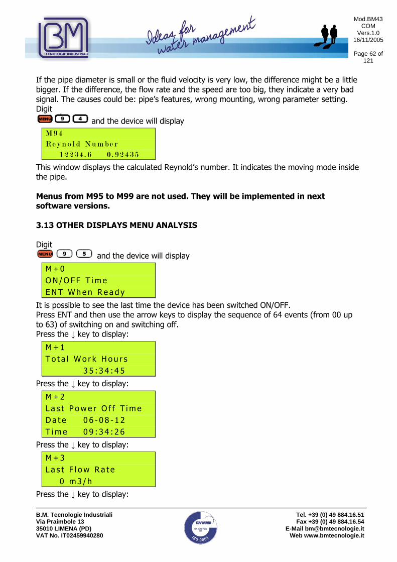
If the pipe diameter is small or the fluid velocity is very low, the difference might be a little bigger. If the difference, the flow rate and the speed are too big, they indicate a very bad signal. The causes could be: pipe’s features, wrong mounting, wrong parameter setting. Digit
and the device will display
M 9 4
R e y n o l d N u m b e r
1 2 2 3 4 . 6 0 . 9 2 4 3 5
This window displays the calculated Reynold’s number. It indicates the moving mode inside the pipe. Menus from M95 to M99 are not used. They will be implemented in next software versions. 3.13 OTHER DISPLAYS MENU ANALYSIS Digit
and the device will display
M + 0
O N / O F F T i m e
E N T W h e n R e a d y
It is possible to see the last time the device has been switched ON/OFF. Press ENT and then use the arrow keys to display the sequence of 64 events (from 00 up to 63) of switching on and switching off. Press the ↓ key to display:
M + 1
T o t a l W o r k H ou r s
3 5 : 3 4 : 4 5
Press the ↓ key to display:
M + 2
L a s t P o w e r O f f T i m e
D a t e 0 6 - 0 8 - 1 2
T i m e 0 9 : 3 4 : 2 6
Press the ↓ key to display:
M + 3
L a s t F l o w R a t e
0 m 3 / h
Press the ↓ key to display:
MENU 9 5

Mod.BM43 COM
Vers.1.0 16/11/2005
Page 63 of
121
B.M. Tecnologie Industriali Via Praimbole 13 35010 LIMENA (PD) VAT No. IT02459940280
Tel. +39 (0) 49 884.16.51 Fax +39 (0) 49 884.16.54
E-Mail [email protected] Web www.bmtecnologie.it
M + 4
O N / O F F T i m e s
1 3 2
Press the ↓ key to display:
C a l c u l a t o r
I n p u t X =
0
It is used as a calculator, setting X value, and then Y value. Press ENT to calculate. Press the ↓ key to display:
M + 6
V e l o c i t y C h a n ge
1 m / s
The set up value is used as a threshold to generate an alarm on the relay or on they OCT when it has been passed. Press the ↓ key to display:
M + 7
P r o t o c o l S e l e c t
0 . P r o t o c o l 0 ( * A dx x )
This function is used to connect the RS232 port to a peculiar device. Press the ↓ key to display:
R C V
S H P _ _ _ _ _ _ _ _ _ _ _
This window displays the signal received from the sensors: GOOD SIGNAL BAD SIGNAL

Mod.BM43 COM
Vers.1.0 16/11/2005
Page 64 of
121
B.M. Tecnologie Industriali Via Praimbole 13 35010 LIMENA (PD) VAT No. IT02459940280
Tel. +39 (0) 49 884.16.51 Fax +39 (0) 49 884.16.54
E-Mail [email protected] Web www.bmtecnologie.it
4. DIAGNOSTICS AND PROBLEM SOLVING The TTFM100B-HH-NG series has a complete series of diagnostics functions: it has a continuous searching for errors or bad working conditions. The continuous displaying of errors helps the customer identifying damages or unacceptable working conditions. Displayed errors could happened:
- When switching on the device, during the initial test. - During functioning, with error codes.
Causes and solutions are indicated in the below following table: 4.1 AUTOTEST DURING SWITCHING ON AND POSSIBLE SOLUTIONS
ERROR DESCRIPTION
SOLUTIONS
ROM PARITY ERROR Contact B.M. Tecnologie Industriali.
STORED DATA ERROR
Digit ENT again during the initial set up.
TIMER SLOW ERROR TIMER FAST ERROR
Switch off and then switch on. If the problem persists, contact B.M. Tecnologie Industriali.
DATE TIME ERROR Set again date and time in menu M61.
4.2 ERROR CODES, CAUSES AND SOLUTIONS DURING FUNCTIONING ERROR CODE
INFORMATION IN M08 WINDOW
CAUSES SOLUTIONS
*R Normal system Regular functioning
*J Sub CPU wrong Damage in sub CPU Contact B.M. Tecnologie Industriali.
*I No signal detected No signal detected: - sensor far fro the
pipe or not so couplant
- wrong sensors mounting
- too many oxide or dump inside the pipe
- new linearity
- check the acoustic contact with the pipe’s surface. - use another couplant - check initial settings - try to reduce the pipe’s internal dumps or change the sensors position - wait for stable linearity.

Mod.BM43 COM
Vers.1.0 16/11/2005
Page 65 of
121
B.M. Tecnologie Industriali Via Praimbole 13 35010 LIMENA (PD) VAT No. IT02459940280
Tel. +39 (0) 49 884.16.51 Fax +39 (0) 49 884.16.54
E-Mail [email protected] Web www.bmtecnologie.it
*H Low strength signal Low signal strength SEE ABOVE
*H Poor quality signal Poor signal quality SEE ABOVE
*F System RAM error Date Time error CPU or IRQ error ROM parity error
Temporary RAM or RTC problem. Permanent Hardware problems.
Switch off and then switch on or contact B.M. Tecnologie Industriali.
*K Empty Pipe Wrong settings in M29 Replace the sensors where the pipe is full. Set “0” in M29.
4.3 OTHER PROBLEMS AND SOLUTIONS
a. If the flow is not static and the device displays a flow rate of 0.0000, the code “R”, and signal strength and quality are satisfying, the problem could have been caused by the user who set a high “zero” value. Solution: reset the device using M42 function. It will restore the factory settings.
b. The device displays a flow rate which is much higher or much lower than what
usually displayed in normal working conditions. - Probably there is a problem with the OFFSET value. Set “0” in M44. - Wrong transducers mounting. - Reset the device by using M41 function. Check that the flow is completely
static.
c. The battery works for a short period. Shorter than what stated in M07. - Replace the battery: it is over. - Contact B.M. Tecnologie Industriali.

Mod.BM43 COM
Vers.1.0 16/11/2005
Page 66 of
121
B.M. Tecnologie Industriali Via Praimbole 13 35010 LIMENA (PD) VAT No. IT02459940280
Tel. +39 (0) 49 884.16.51 Fax +39 (0) 49 884.16.54
E-Mail [email protected] Web www.bmtecnologie.it
5. COMMUNICATION WITH A PC AND/ OR DATA LOGGING This chapter informs the user about the hardware connections to be done to allow a communication between the device and the pc. 5.1 REQUIRED HARDWARE It is possible to connect a notebook to the device by using the serial port RS232-C: in this way it will be possible to download data or send signals to the TTFM100 series. Use a serial cable with a female DB9 connector on both sides. It is possible to buy the cable in almost every electronic shops, it is a very common cable. If you want, you could also made it by yourselves, please follow the instructions: 9 POLES FEMALE 9 POLE FEMALE CONNECTOR CONNECTOR
5.2 COMPLETE PIN-OUT OF DB9 M DOOR
PIN CONNECTION TO…
1 Battery charger Positive pole input (+)
2 RXD- Received data
3 TXD- Sent data
4 Not Used
5 GND- Back signals
6 OCT Output- Positive Pole output (+)
7 Not Used
8 Battery charger Negative pole input (-)
9 RING input for MODEM connection

Mod.BM43 COM
Vers.1.0 16/11/2005
Page 67 of
121
B.M. Tecnologie Industriali Via Praimbole 13 35010 LIMENA (PD) VAT No. IT02459940280
Tel. +39 (0) 49 884.16.51 Fax +39 (0) 49 884.16.54
E-Mail [email protected] Web www.bmtecnologie.it
5.3 DIRECT CONTROL- COMMUNICATION PROTOCOL
CONTROL FUNCTION
DQD (CR) DAILY FLOW RATE
DQH(CR) HOUR FLOW RATE
DQM(CR) MINUTE FLOW RATE
DQS(CR) SECOND FLOW RATE
DV(CR) FLOW RATE SPEED
DI+(CR) POSITIVE TOTALIZER
DI-(CR) NEGATIVE TOTALIZER
DIN(CR) NET TOTALIZER
DID(CR) ID NUMBER
DL(CR) SIGNAL STRENGTH & QUALITY
DT(CR) CURRENT DATE AND TIME
M@(CR)*** VALUE OF PRESSED KEY
LCD (CR) DISPLAY CONTENT
FOdddd (CR) OUTPUT FREQUENCE OF ddddHz VALUE
ESN (CR) ESN DEVICE NUMBER
RING (CR) MODEM COMMUNICATION MANAGING
OK (CR) MODEM RESPONSE
GA CONTROL FOR MESSAGES TO A GSM
GB CONTROL FOR MESSAGES TO A GSM
GC CONTROL FOR MESSAGES TO A GSM
DUMP (CR) BUFFER CONTENT
DUMP0 (CR) CLEANING OF BUFFER CONTENT
DUMP1 (CR) COMPLETE BUFFER CONTENT PREFIX BEFORE NETWORK ID NUMBER.
N PREFIX BEFORE NETWORK ID NUMBER.
P PREFIX BEFORE EACH CONTROL
& CONNECTOR USED TO LOAD UP TO 6 CONTROLS.
(CR)= CHANGE OF LINE “d”= DIGIT BETWEEN 0…9 @= KEY VALUE.

Mod.BM43 COM
Vers.1.0 16/11/2005
Page 68 of
121
B.M. Tecnologie Industriali Via Praimbole 13 35010 LIMENA (PD) VAT No. IT02459940280
Tel. +39 (0) 49 884.16.51 Fax +39 (0) 49 884.16.54
E-Mail [email protected] Web www.bmtecnologie.it
5.4 USE OF THE PREFIX IN THE CONTROL
a. PREFIX P: The P prefix is added before starting a control indicated in the above mentioned list, in order to obtain a 2 byte control on the CRC code.
Example: control DI+ (CR). The device replies with a value of +1234567E+m3(CR)(LF), the converted hexadecimal line is 2BH, 31H, 32H, 33H, 34H, 35H, 36H, 37H, 45H, 2BH, 30H, 6DH, 33H, 20H, ODH, 0AH. The same control with prefix P will be PDI+(CR), the device will reply giving a value of +1234567E+m3!F7(CR)(LF). “!” acts as a control start for summing the line values, 2BH, 31H, 32H, 33H, 34H, 35H, 36H, 37H, 45H, 2BH, 30H, 6DH, 33H, 20H. Before “!” there will be som free spaces (20H).
PREFIX W: it is used to control a net of devices for addressing the control’s receiver device. Synthax composed of: IDN + base control. It is possibile to use various ID between 0 and 65534, but 13 (0DH), 10 (0AH), 42 (2AH,*),38 (26H,&).
Example: if IDN is 12345 and you want to calcolate the speed value of the addressed device, the control to be used will be W12345DV(CR).
b. PREFIX N: it not used anymore in the new versions of TTFM100B.
c. CONNECTION CONTROL &: the & control permits to establish a connection up to 6 simple controls in order to speed up a devices questionnaire.
Example: we are asking to a device connected to a net with IDN=1234, the following information: Flow rate, Speed and POs Totalizer. The control will be: W1234DQD&DV&DI+(CR), the reply will be +1.234567E+12m3/d(CR) +3.123456E+00m/s(CR) +1234567E+0m3(CR)

Mod.BM43 COM
Vers.1.0 16/11/2005
Page 69 of
121
B.M. Tecnologie Industriali Via Praimbole 13 35010 LIMENA (PD) VAT No. IT02459940280
Tel. +39 (0) 49 884.16.51 Fax +39 (0) 49 884.16.54
E-Mail [email protected] Web www.bmtecnologie.it
5.5 KEYPAD CODES
Key HEX Code
Key Code
ASCII Code
Key HEX Code
Key Code
ASCII Code
30H 48 0 38H 56 8
31H 49 1 39H 57 9
32H 50 2 3AH 58 :
33H 51 3 3BH,0BH 59 ;
34H 52 4 3CH,0CH 60 <
35H 53 5 3DH,0DH 61 =
36H 54 6 3EH 62 >
37H 55 7 3FH 63 ?
0 8
1 9
2 .
3 4 MENU
5 ENT
6 /+
7 /-

Mod.BM43 COM
Vers.1.0 16/11/2005
Page 70 of
121
B.M. Tecnologie Industriali Via Praimbole 13 35010 LIMENA (PD) VAT No. IT02459940280
Tel. +39 (0) 49 884.16.51 Fax +39 (0) 49 884.16.54
E-Mail [email protected] Web www.bmtecnologie.it
6. APPENDIX 6.1 SOUND SPEEDS IN SOLIDS

Mod.BM43 COM
Vers.1.0 16/11/2005
Page 71 of
121
B.M. Tecnologie Industriali Via Praimbole 13 35010 LIMENA (PD) VAT No. IT02459940280
Tel. +39 (0) 49 884.16.51 Fax +39 (0) 49 884.16.54
E-Mail [email protected] Web www.bmtecnologie.it

Mod.BM43 COM
Vers.1.0 16/11/2005
Page 72 of
121
B.M. Tecnologie Industriali Via Praimbole 13 35010 LIMENA (PD) VAT No. IT02459940280
Tel. +39 (0) 49 884.16.51 Fax +39 (0) 49 884.16.54
E-Mail [email protected] Web www.bmtecnologie.it
6.2 SOUND SPEEDS IN FLUIDS
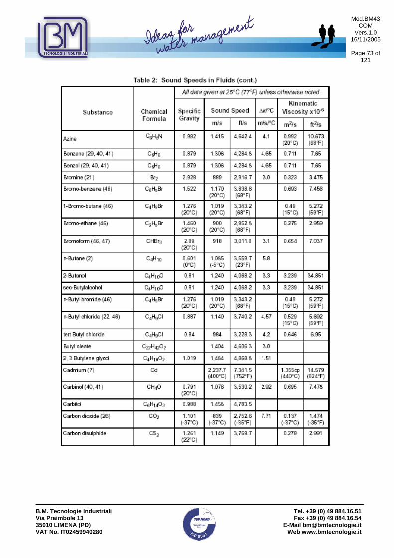
Mod.BM43 COM
Vers.1.0 16/11/2005
Page 73 of
121
B.M. Tecnologie Industriali Via Praimbole 13 35010 LIMENA (PD) VAT No. IT02459940280
Tel. +39 (0) 49 884.16.51 Fax +39 (0) 49 884.16.54
E-Mail [email protected] Web www.bmtecnologie.it

Mod.BM43 COM
Vers.1.0 16/11/2005
Page 74 of
121
B.M. Tecnologie Industriali Via Praimbole 13 35010 LIMENA (PD) VAT No. IT02459940280
Tel. +39 (0) 49 884.16.51 Fax +39 (0) 49 884.16.54
E-Mail [email protected] Web www.bmtecnologie.it

Mod.BM43 COM
Vers.1.0 16/11/2005
Page 75 of
121
B.M. Tecnologie Industriali Via Praimbole 13 35010 LIMENA (PD) VAT No. IT02459940280
Tel. +39 (0) 49 884.16.51 Fax +39 (0) 49 884.16.54
E-Mail [email protected] Web www.bmtecnologie.it

Mod.BM43 COM
Vers.1.0 16/11/2005
Page 76 of
121
B.M. Tecnologie Industriali Via Praimbole 13 35010 LIMENA (PD) VAT No. IT02459940280
Tel. +39 (0) 49 884.16.51 Fax +39 (0) 49 884.16.54
E-Mail [email protected] Web www.bmtecnologie.it

Mod.BM43 COM
Vers.1.0 16/11/2005
Page 77 of
121
B.M. Tecnologie Industriali Via Praimbole 13 35010 LIMENA (PD) VAT No. IT02459940280
Tel. +39 (0) 49 884.16.51 Fax +39 (0) 49 884.16.54
E-Mail [email protected] Web www.bmtecnologie.it

Mod.BM43 COM
Vers.1.0 16/11/2005
Page 78 of
121
B.M. Tecnologie Industriali Via Praimbole 13 35010 LIMENA (PD) VAT No. IT02459940280
Tel. +39 (0) 49 884.16.51 Fax +39 (0) 49 884.16.54
E-Mail [email protected] Web www.bmtecnologie.it

Mod.BM43 COM
Vers.1.0 16/11/2005
Page 79 of
121
B.M. Tecnologie Industriali Via Praimbole 13 35010 LIMENA (PD) VAT No. IT02459940280
Tel. +39 (0) 49 884.16.51 Fax +39 (0) 49 884.16.54
E-Mail [email protected] Web www.bmtecnologie.it

Mod.BM43 COM
Vers.1.0 16/11/2005
Page 80 of
121
B.M. Tecnologie Industriali Via Praimbole 13 35010 LIMENA (PD) VAT No. IT02459940280
Tel. +39 (0) 49 884.16.51 Fax +39 (0) 49 884.16.54
E-Mail [email protected] Web www.bmtecnologie.it

Mod.BM43 COM
Vers.1.0 16/11/2005
Page 81 of
121
B.M. Tecnologie Industriali Via Praimbole 13 35010 LIMENA (PD) VAT No. IT02459940280
Tel. +39 (0) 49 884.16.51 Fax +39 (0) 49 884.16.54
E-Mail [email protected] Web www.bmtecnologie.it

Mod.BM43 COM
Vers.1.0 16/11/2005
Page 82 of
121
B.M. Tecnologie Industriali Via Praimbole 13 35010 LIMENA (PD) VAT No. IT02459940280
Tel. +39 (0) 49 884.16.51 Fax +39 (0) 49 884.16.54
E-Mail [email protected] Web www.bmtecnologie.it

Mod.BM43 COM
Vers.1.0 16/11/2005
Page 83 of
121
B.M. Tecnologie Industriali Via Praimbole 13 35010 LIMENA (PD) VAT No. IT02459940280
Tel. +39 (0) 49 884.16.51 Fax +39 (0) 49 884.16.54
E-Mail [email protected] Web www.bmtecnologie.it

Mod.BM43 COM
Vers.1.0 16/11/2005
Page 84 of
121
B.M. Tecnologie Industriali Via Praimbole 13 35010 LIMENA (PD) VAT No. IT02459940280
Tel. +39 (0) 49 884.16.51 Fax +39 (0) 49 884.16.54
E-Mail [email protected] Web www.bmtecnologie.it

Mod.BM43 COM
Vers.1.0 16/11/2005
Page 85 of
121
B.M. Tecnologie Industriali Via Praimbole 13 35010 LIMENA (PD) VAT No. IT02459940280
Tel. +39 (0) 49 884.16.51 Fax +39 (0) 49 884.16.54
E-Mail [email protected] Web www.bmtecnologie.it

Mod.BM43 COM
Vers.1.0 16/11/2005
Page 86 of
121
B.M. Tecnologie Industriali Via Praimbole 13 35010 LIMENA (PD) VAT No. IT02459940280
Tel. +39 (0) 49 884.16.51 Fax +39 (0) 49 884.16.54
E-Mail [email protected] Web www.bmtecnologie.it
6.3 SOUND SPEEDS IN WATER AT SELECTED TEMPERATURES

Mod.BM43 COM
Vers.1.0 16/11/2005
Page 87 of
121
B.M. Tecnologie Industriali Via Praimbole 13 35010 LIMENA (PD) VAT No. IT02459940280
Tel. +39 (0) 49 884.16.51 Fax +39 (0) 49 884.16.54
E-Mail [email protected] Web www.bmtecnologie.it

Mod.BM43 COM
Vers.1.0 16/11/2005
Page 88 of
121
B.M. Tecnologie Industriali Via Praimbole 13 35010 LIMENA (PD) VAT No. IT02459940280
Tel. +39 (0) 49 884.16.51 Fax +39 (0) 49 884.16.54
E-Mail [email protected] Web www.bmtecnologie.it
6.4 PIPE SIZE DATA

Mod.BM43 COM
Vers.1.0 16/11/2005
Page 89 of
121
B.M. Tecnologie Industriali Via Praimbole 13 35010 LIMENA (PD) VAT No. IT02459940280
Tel. +39 (0) 49 884.16.51 Fax +39 (0) 49 884.16.54
E-Mail [email protected] Web www.bmtecnologie.it
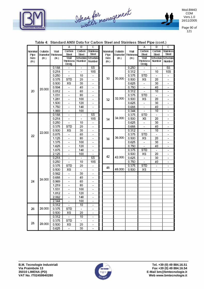
Mod.BM43 COM
Vers.1.0 16/11/2005
Page 90 of
121
B.M. Tecnologie Industriali Via Praimbole 13 35010 LIMENA (PD) VAT No. IT02459940280
Tel. +39 (0) 49 884.16.51 Fax +39 (0) 49 884.16.54
E-Mail [email protected] Web www.bmtecnologie.it

Mod.BM43 COM
Vers.1.0 16/11/2005
Page 91 of
121
B.M. Tecnologie Industriali Via Praimbole 13 35010 LIMENA (PD) VAT No. IT02459940280
Tel. +39 (0) 49 884.16.51 Fax +39 (0) 49 884.16.54
E-Mail [email protected] Web www.bmtecnologie.it

Mod.BM43 COM
Vers.1.0 16/11/2005
Page 92 of
121
B.M. Tecnologie Industriali Via Praimbole 13 35010 LIMENA (PD) VAT No. IT02459940280
Tel. +39 (0) 49 884.16.51 Fax +39 (0) 49 884.16.54
E-Mail [email protected] Web www.bmtecnologie.it

Mod.BM43 COM
Vers.1.0 16/11/2005
Page 93 of
121
B.M. Tecnologie Industriali Via Praimbole 13 35010 LIMENA (PD) VAT No. IT02459940280
Tel. +39 (0) 49 884.16.51 Fax +39 (0) 49 884.16.54
E-Mail [email protected] Web www.bmtecnologie.it
7. EC- DECALARATION OF CONFORMITY
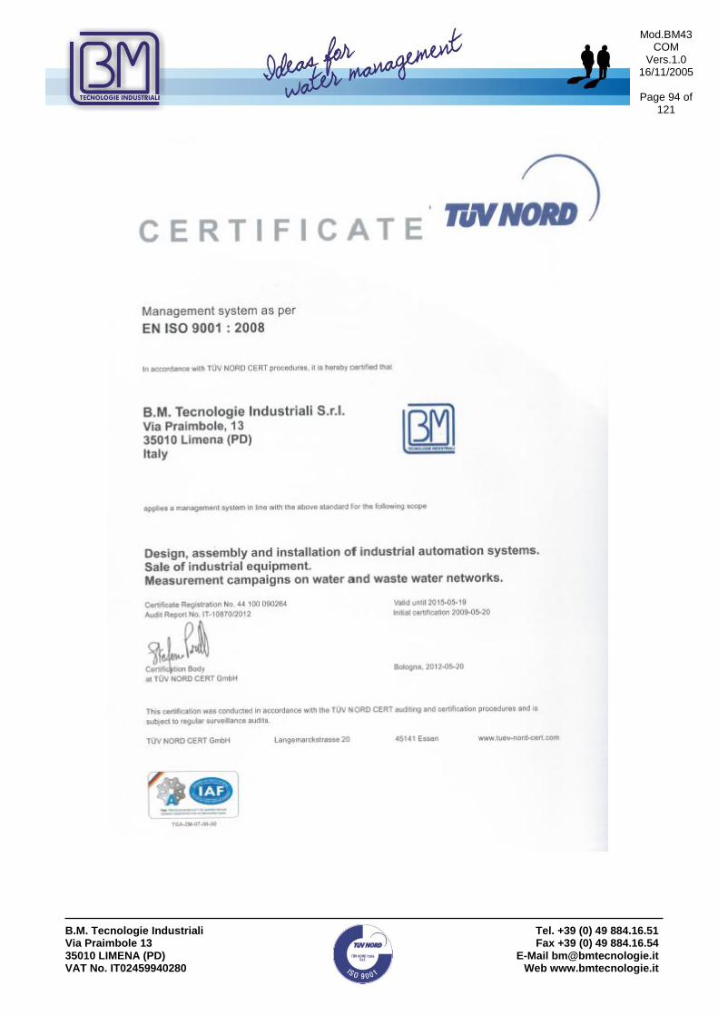
Mod.BM43 COM
Vers.1.0 16/11/2005
Page 94 of
121
B.M. Tecnologie Industriali Via Praimbole 13 35010 LIMENA (PD) VAT No. IT02459940280
Tel. +39 (0) 49 884.16.51 Fax +39 (0) 49 884.16.54
E-Mail [email protected] Web www.bmtecnologie.it

Mod.BM43 COM
Vers.1.0 16/11/2005
Page 95 of
121
B.M. Tecnologie Industriali Via Praimbole 13 35010 LIMENA (PD) VAT No. IT02459940280
Tel. +39 (0) 49 884.16.51 Fax +39 (0) 49 884.16.54
E-Mail [email protected] Web www.bmtecnologie.it
Because of B.M. Tecnologie Industriali policy of improving their products, the TTFM100 series, would be revised and improved. Please inform us about misunderstandings or errors which You may find in this manual comparing it to the device You bought. Do not hesitate to contact us to suggest how to improve our devices, thank You.
B.M. TECNOLOGIE INDUSTRIALI s.r.l.
Via Praimbole, 13- 35010 LIMENA (PD)- ITALY
Tel. +39(0)49-8841651 – Fax +39(0)49-8841654
e-mail: [email protected] web: www.bmtecologie.it

Mod.BM43 COM
Vers.1.0 16/11/2005
Page 96 of
121
B.M. Tecnologie Industriali Via Praimbole 13 35010 LIMENA (PD) VAT No. IT02459940280
Tel. +39 (0) 49 884.16.51 Fax +39 (0) 49 884.16.54
E-Mail [email protected] Web www.bmtecnologie.it
Ultrasonic Transit Time Flowmeter
TTFM100 SERIES
RS232 Data Logger

Mod.BM43 COM
Vers.1.0 16/11/2005
Page 97 of
121
B.M. Tecnologie Industriali Via Praimbole 13 35010 LIMENA (PD) VAT No. IT02459940280
Tel. +39 (0) 49 884.16.51 Fax +39 (0) 49 884.16.54
E-Mail [email protected] Web www.bmtecnologie.it
1. WORKING PRINCIPLE ------------------------------------------------------------------------------- 6
1.1 TYPICAL USE ------------------------------------------------------------------------------------------- 7
1.2 PACKING LIST ------------------------------------------ ERRORE. IL SEGNALIBRO NON È DEFINITO.
2.3 A PRACTICAL EXAMPLE OF RAPID SETTINGS--------------------------------------------------- 12 2.3.1 Fluid & pipe’s features --------------------------------------------------------------------------------------- 12
2.3.2 Data entry ---------------------------------------------------------------------------------------------------------- 12
2.4 INSTRUCTIONS FOR CLAMP-ON SENSORS INSTALLATION --------------------------------- 17
ULTRASONIC TRANSIT TIME FLOWMETER ------------------------------------------------------ 96
TTFM100 SERIES -------------------------------------------------------------------------------------------- 96
RS232 DATA LOGGER ------------------------------------------------------------------------------------- 96
1. REQUIRED HARDWARE ------------------------------------------------------------------------------- 98
2. INITIAL SETTINGS FOR DATA LOGGER FUNCTION -------------------------------------- 98
2.1 TTFM100 – TTFM100B SETTINGS (WALL MOUNT AND PORTABLE) -------------------------------- 99
2.2 HARDWARE CONNECTIONS BETWEEN TTFM100 & PC ----------------------------------------------- 101
3. HOW TO USE EXCEL© TO READ THE .TXT DATA ------------------------------------------ 105
3.1 HOW TO IMPORT .TXT FILES IN EXCEL©
--------------------------------------------------------------- 105
3.2 AN EXAMPLE OF FLOW RATE BAR GRAPH --------------------------------------------------------------- 109

Mod.BM43 COM
Vers.1.0 16/11/2005
Page 98 of
121
B.M. Tecnologie Industriali Via Praimbole 13 35010 LIMENA (PD) VAT No. IT02459940280
Tel. +39 (0) 49 884.16.51 Fax +39 (0) 49 884.16.54
E-Mail [email protected] Web www.bmtecnologie.it
It is supposed to have some Personal Computer (PC) knowledge before starting reading this manual.
The information listed below is of general kind. Please be informed that a Laptop PC with Windows© XP© Operating System.
1. Required Hardware For information about the serial port and the connection cable, please refer to Chapter 5 of TTFM100 instruction manual.
Note:
Your PC has normally more than one USB ports so you need a converter for the serial connection to TTFM100 series instrument. If you use the wall mounted version, you need a RS485 to USB converter. If you use the portable version, you need a RS232 to USB converter During the set-up and the data logging, the port number the system gives to the added USB serial converter is required; please check it in “Device Manager” Window. In the picture the Comm. Port number is “COM7”.
2. Initial settings for Data Logger Function Please Ref. to Chapter 3.10.1 for a general description of Data Logger function. In the following example, only a few measures, available on the serial port RS485-RS232, are set as ON. Other measures COULD NOT BE. It is supposed the PC is ready to work. Normally with the operating system, there is a program to perform serial communications between various devices and a PC. In this case we use a direct connection (without any modem) and the following example is based on RS232 Data Logger©. The latest can be downloaded for free form the Internet.

Mod.BM43 COM
Vers.1.0 16/11/2005
Page 99 of
121
B.M. Tecnologie Industriali Via Praimbole 13 35010 LIMENA (PD) VAT No. IT02459940280
Tel. +39 (0) 49 884.16.51 Fax +39 (0) 49 884.16.54
E-Mail [email protected] Web www.bmtecnologie.it
2.1 TTFM100 – TTFM100B Settings (Wall mount and Portable)
Note:
The hand held type TTFM100B does not give information about the analog signals and the calorimeter, but all the other settings are the same. The TTFM100B display has a different format but the information are the same.
Wall Mounted Version Hand Held Version Press
D a t a L o g ge r O p t i o n
O N
M 5 0 L o g g e r O p t i o n O N
D a t a L o g ge r S e t u p [ 5 1
N e x t = x x : x x : x x X X X X
M 5 1 L o gg e r S e t u p S t a r t * * : * * : * * I n t e r v a l 0 0 : 0 0 : 3 0
G o O n * * : * * : * *
D a t a L o g ge r S e t u p [ 5 1
S t a r t T i m e = * * : * * : * *
M 5 2 D a t a D i r e c t i o n 1 . T o B u f f e r
D a t a L o g ge r S e t u p [ 5 1
I n t e r v a l = 0 0 : 0 0 : 3 0
M 5 3 B u f f e r V i e w e r P r e s s E N T t o g o
D a t a L o g ge r S e t u p [ 5 1
L o g T i m e s = 1 0 0 0
D a t a L o g g e r S e t u p [ 5 1
N e x t = x x : x x : x x X X X X
MENU 5 0
MENU 5 1
/-
/-
/-

Mod.BM43 COM
Vers.1.0 16/11/2005
Page 100
of 121
B.M. Tecnologie Industriali Via Praimbole 13 35010 LIMENA (PD) VAT No. IT02459940280
Tel. +39 (0) 49 884.16.51 Fax +39 (0) 49 884.16.54
E-Mail [email protected] Web www.bmtecnologie.it
The following table, for example, shows the measure ON for the instruments, wall mount and hand held.
WALL MOUNT SET PORTABLE SET
0. Date and Time ON 0.
1. System Status ON 1. Date and Time ON
2. Current Window OFF 2. System Status ON
3. Signal Strength ON 3. Current Window OFF
4. Flow Rate ON 4. Flow Rate ON
5. Velocity ON 5. Velocity ON
6. NET Totalized OFF 6. NET Totalized OFF
7. POS Totalized ON 7. POS Totalized ON
8. NEG Totalized OFF 8. NEG Totalized OFF
9. Energy Flow Rate OFF 9. Signal Strength ON
10. Energy NET Total OFF 10. Working Timer OFF
11. Energy POS Total OFF 11. Flow Today OFF
12. Energy NEG Total OFF Not applicable
13. Fluid Velocity OFF Not applicable
14. RTD T1 OFF Not applicable
15. RTD T2 OFF Not applicable
16. Analog Input 3 OFF Not applicable
17. Analog Input 4 OFF Not applicable
18. Analog Input 5 OFF Not applicable
19. Working Timer OFF Not applicable
20. Flow Today OFF Not applicable
21. Serial Number OFF Not applicable

Mod.BM43 COM
Vers.1.0 16/11/2005
Page 101
of 121
B.M. Tecnologie Industriali Via Praimbole 13 35010 LIMENA (PD) VAT No. IT02459940280
Tel. +39 (0) 49 884.16.51 Fax +39 (0) 49 884.16.54
E-Mail [email protected] Web www.bmtecnologie.it
2.2 Hardware connections between TTFM100 & PC
For stationary units, connect the device serial cable to the serial port RS485 and to the PC. You need a RS485 or RS232 converter to USB, depending from the laptop you are using.
Serial converter RS485 to USB

Mod.BM43 COM
Vers.1.0 16/11/2005
Page 102
of 121
B.M. Tecnologie Industriali Via Praimbole 13 35010 LIMENA (PD) VAT No. IT02459940280
Tel. +39 (0) 49 884.16.51 Fax +39 (0) 49 884.16.54
E-Mail [email protected] Web www.bmtecnologie.it
For hand held units, connect the devices serial cable to the serial port RS232 and to the PC.
In this particular case we used an RS232/USB converter. It was connected with a short cable to a PC’s USB port.

Mod.BM43 COM
Vers.1.0 16/11/2005
Page 103
of 121
B.M. Tecnologie Industriali Via Praimbole 13 35010 LIMENA (PD) VAT No. IT02459940280
Tel. +39 (0) 49 884.16.51 Fax +39 (0) 49 884.16.54
E-Mail [email protected] Web www.bmtecnologie.it
2.3 Connection software between PC & TTFM100 series The most important function needed in a serial connection management program is the possibility of acquiring data from a serial connection. There are many programs able to do this but we suggest to use a free program from http://sourceforge.net/projects/rs232portlogger/ It can be supplied along with the manuals and it is completely free. After its installation the main window looks like this.
With this button you can set the name_file
You must set the same parameter as in
the of the wall mounting or hand held unit.
Choose the AVAILABLE COM port!
MENU 6 2StartLoggin / StopLogging button.

Mod.BM43 COM
Vers.1.0 16/11/2005
Page 104
of 121
B.M. Tecnologie Industriali Via Praimbole 13 35010 LIMENA (PD) VAT No. IT02459940280
Tel. +39 (0) 49 884.16.51 Fax +39 (0) 49 884.16.54
E-Mail [email protected] Web www.bmtecnologie.it
Before StartLogging go to M52 menu window and choose Buffer to RS232 selection
M 5 2
D a t a D i r e c t i o n
1 . T o B u f f e r
= > B u f f e r > R S 2 3 2
Click on StartLogging and than on ENT button on TTFM100. You could see immediately the bytes received counter increasing.
If you have thick the “ ” box the data will be appended to the same filename. The total bytes in the file will be the result of adding one or more files.
When the download is complete, press the button. Now the saved file will be saved in the defined directory:

Mod.BM43 COM
Vers.1.0 16/11/2005
Page 105
of 121
B.M. Tecnologie Industriali Via Praimbole 13 35010 LIMENA (PD) VAT No. IT02459940280
Tel. +39 (0) 49 884.16.51 Fax +39 (0) 49 884.16.54
E-Mail [email protected] Web www.bmtecnologie.it
3. How to use Excel© to read the .txt data The following paragraph will only give a general information about how to manage the data logged with the previous indicated functions.
3.1 How to import .TXT files in Excel© The user who wants to use this option must have a minimum Excel© knowledge: all the procedures for opening and searching for files in the PC directories must be known. Start the program and open a logged file (this file should have been logged during a regular TTFM100 functioning). The following example uses a file called TEST_CAPTURED_FILE.TXT. In the last example we used “My Documents” folder to store the captured file. Attention: in order to display that file, please select “All files” (*.*).
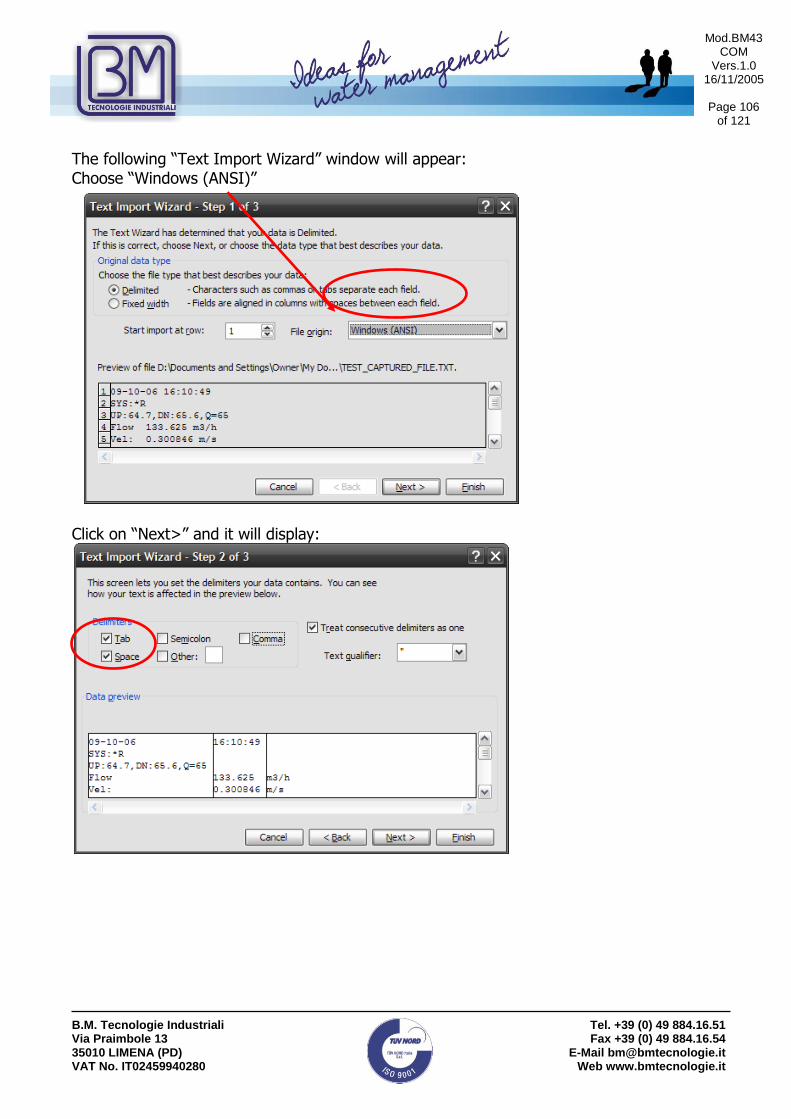
Mod.BM43 COM
Vers.1.0 16/11/2005
Page 106
of 121
B.M. Tecnologie Industriali Via Praimbole 13 35010 LIMENA (PD) VAT No. IT02459940280
Tel. +39 (0) 49 884.16.51 Fax +39 (0) 49 884.16.54
E-Mail [email protected] Web www.bmtecnologie.it
The following “Text Import Wizard” window will appear: Choose “Windows (ANSI)”
Click on “Next>” and it will display:

Mod.BM43 COM
Vers.1.0 16/11/2005
Page 107
of 121
B.M. Tecnologie Industriali Via Praimbole 13 35010 LIMENA (PD) VAT No. IT02459940280
Tel. +39 (0) 49 884.16.51 Fax +39 (0) 49 884.16.54
E-Mail [email protected] Web www.bmtecnologie.it
Please pay attention to choose “Tab” and “Space” tag and click on “Next>” button. Now it displays:
Click on “Advanced...” button:
This window requires the decimal separator to be defined as dot “.” and the thousands separator as comma “,”. Click on OK. Go back to the previous window and set the data format in order to have a correct import. Select YMG that means year – month – day. Then click on “Finish” to complete the data import.

Mod.BM43 COM
Vers.1.0 16/11/2005
Page 108
of 121
B.M. Tecnologie Industriali Via Praimbole 13 35010 LIMENA (PD) VAT No. IT02459940280
Tel. +39 (0) 49 884.16.51 Fax +39 (0) 49 884.16.54
E-Mail [email protected] Web www.bmtecnologie.it
It is possible to change the columns width in order to display the date correctly. For example: Click with the mouse right key on “Column A” and then click on “Column Width” and set it to 12. It is necessary to re-elaborate the data because of the disposition in columns and lines. In fact it does not permit to create a reliable bar graph of the desired measures. The menu called “Data” helps the user to extract data, for example: the flow rate is the temporary date hour: minute: sec (h: m: s).

Mod.BM43 COM
Vers.1.0 16/11/2005
Page 109
of 121
B.M. Tecnologie Industriali Via Praimbole 13 35010 LIMENA (PD) VAT No. IT02459940280
Tel. +39 (0) 49 884.16.51 Fax +39 (0) 49 884.16.54
E-Mail [email protected] Web www.bmtecnologie.it
3.2 An example of Flow Rate Bar graph
Select the first 3 columns “A-B-C” and click on “Automatic Filter” as follows:
3 tags will appear on the upper right corner of each column:
Click on the first tag and select the acquisition date line (it is assumed that the day is the same for all the columns!!).

Mod.BM43 COM
Vers.1.0 16/11/2005
Page 110
of 121
B.M. Tecnologie Industriali Via Praimbole 13 35010 LIMENA (PD) VAT No. IT02459940280
Tel. +39 (0) 49 884.16.51 Fax +39 (0) 49 884.16.54
E-Mail [email protected] Web www.bmtecnologie.it
Excel will now extract the data into the lines according to the searching criteria.
The date referes to the hour in which the flow rate was logged. During the text file import, Excel generated only one sheet in the folder, but at least another sheet is needed in order to manage this data extraction.

Mod.BM43 COM
Vers.1.0 16/11/2005
Page 111
of 121
B.M. Tecnologie Industriali Via Praimbole 13 35010 LIMENA (PD) VAT No. IT02459940280
Tel. +39 (0) 49 884.16.51 Fax +39 (0) 49 884.16.54
E-Mail [email protected] Web www.bmtecnologie.it
Click on “Insert”, click on “Worksheet” and a new sheet will appear, named “Sheet 1”. Return to the original sheet. Select the data into the hour column, and copy them.
Go to sheet 1 and paste the copied data.

Mod.BM43 COM
Vers.1.0 16/11/2005
Page 112
of 121
B.M. Tecnologie Industriali Via Praimbole 13 35010 LIMENA (PD) VAT No. IT02459940280
Tel. +39 (0) 49 884.16.51 Fax +39 (0) 49 884.16.54
E-Mail [email protected] Web www.bmtecnologie.it
Now the acquisition time data are ok, but the flow data are still missing. Go back to the original sheet and click on the first tag, selecting Flow.

Mod.BM43 COM
Vers.1.0 16/11/2005
Page 113
of 121
B.M. Tecnologie Industriali Via Praimbole 13 35010 LIMENA (PD) VAT No. IT02459940280
Tel. +39 (0) 49 884.16.51 Fax +39 (0) 49 884.16.54
E-Mail [email protected] Web www.bmtecnologie.it
Now the B column will display the flow data. The C column will display the flow rate engineering units. Select and copy the flow data, as done for the time data, and paste them in “Sheet 1”

Mod.BM43 COM
Vers.1.0 16/11/2005
Page 114
of 121
B.M. Tecnologie Industriali Via Praimbole 13 35010 LIMENA (PD) VAT No. IT02459940280
Tel. +39 (0) 49 884.16.51 Fax +39 (0) 49 884.16.54
E-Mail [email protected] Web www.bmtecnologie.it
Now the data for the X axe and Y axe of the graph are complete. Select the 2 group of data: Go to “Insert”, “Chart”
Now the type of Chart should be selected. Go into the Chart Wizard selection table and choose, for example, “XY (Scatter)” and then click on “Next” button.

Mod.BM43 COM
Vers.1.0 16/11/2005
Page 115
of 121
B.M. Tecnologie Industriali Via Praimbole 13 35010 LIMENA (PD) VAT No. IT02459940280
Tel. +39 (0) 49 884.16.51 Fax +39 (0) 49 884.16.54
E-Mail [email protected] Web www.bmtecnologie.it
The following window will be displayed:
It is possible to see the type of chart displaying the time flow rate. Click on “Next” button.

Mod.BM43 COM
Vers.1.0 16/11/2005
Page 116
of 121
B.M. Tecnologie Industriali Via Praimbole 13 35010 LIMENA (PD) VAT No. IT02459940280
Tel. +39 (0) 49 884.16.51 Fax +39 (0) 49 884.16.54
E-Mail [email protected] Web www.bmtecnologie.it
It is possible to scroll all the display options or go directly to the 4th screen.
Click on “Next>”. The last window will be displayed: It is suggested to create the chart into a new sheet, Chart1 in the example windows. Then Click on “Finish”.

Mod.BM43 COM
Vers.1.0 16/11/2005
Page 117
of 121
B.M. Tecnologie Industriali Via Praimbole 13 35010 LIMENA (PD) VAT No. IT02459940280
Tel. +39 (0) 49 884.16.51 Fax +39 (0) 49 884.16.54
E-Mail [email protected] Web www.bmtecnologie.it
Now the final graph will be displayed.

Mod.BM43 COM
Vers.1.0 16/11/2005
Page 118
of 121
B.M. Tecnologie Industriali Via Praimbole 13 35010 LIMENA (PD) VAT No. IT02459940280
Tel. +39 (0) 49 884.16.51 Fax +39 (0) 49 884.16.54
E-Mail [email protected] Web www.bmtecnologie.it
How to check the COM port set up in TTFM100B Digit
and the device will display
M 6 2
R S - 2 3 2 C S e t u p
B a u d r a t e : = 9 6 0 0 ,
P a r i t y : N o n e
This window is used to set up the communication parameters of the serial port. Press ENT and then use the arrow keys to select among: Baud Rate:
75 110 150 300 600 1200 2400 3600 4800 9600 19200 28800 38400 57600 115200
Press ENT to confirm the selected option and then select the parity type among:
None Even Odd
Press ENT to confirm the selection and exit the setting. The other parameters are factory set up: 8 bit data, 1 bit stop and none flow control Xon/Xoff.

Mod.BM43 COM
Vers.1.0 16/11/2005
Page 119
of 121
B.M. Tecnologie Industriali Via Praimbole 13 35010 LIMENA (PD) VAT No. IT02459940280
Tel. +39 (0) 49 884.16.51 Fax +39 (0) 49 884.16.54
E-Mail [email protected] Web www.bmtecnologie.it
EC- DECLARATION OF CONFORMITY

Mod.BM43 COM
Vers.1.0 16/11/2005
Page 120
of 121
B.M. Tecnologie Industriali Via Praimbole 13 35010 LIMENA (PD) VAT No. IT02459940280
Tel. +39 (0) 49 884.16.51 Fax +39 (0) 49 884.16.54
E-Mail [email protected] Web www.bmtecnologie.it

Mod.BM43 COM
Vers.1.0 16/11/2005
Page 121
of 121
B.M. Tecnologie Industriali Via Praimbole 13 35010 LIMENA (PD) VAT No. IT02459940280
Tel. +39 (0) 49 884.16.51 Fax +39 (0) 49 884.16.54
E-Mail [email protected] Web www.bmtecnologie.it
Because of B.M. Tecnologie Industriali’s policy of improving their products, the TTFM100 series, would be revised and improved. Please inform us about misunderstandings or errors which you may find in this manual comparing it to the device you bought. Do not hesitate to contact us to suggest how to improve our devices, thank You.
B.M. Tecnologie Industriali S.r.l. – Technical Dept.
B.M. Tecnologie Industriali s.r.l.
Via Praimbole,13 – 35010 LIMENA (PD) – ITALY
Tel. 0039.049.8841651 – Fax 0039.049.8841654
E-Mail [email protected] - Web www.bmtecnologie.it