ultrasonic intrinsic tagging for nuclear disarmament: a
TRANSCRIPT

PNNL-14462
Ultrasonic Intrinsic Tagging for Nuclear Disarmament: A Proof-of-Concept Test M.S. Good J.R. Skorpik B.E. Simpkins J.A. Willett J.L. Kirihara October 2003 Prepared for Office of Nonproliferation Policy, NA-241 Department of Energy Forrestal Building 1000 Independence Avenue, SW Washington, D.C. 20585 Prepared for the U.S. Department of Energy under Contract DE-AC06-76RL01830

DISCLAIMER This report was prepared as an account of work sponsored by an agency of the United States Government. Neither the United States Government nor any agency thereof, nor Battelle Memorial Institute, nor any of their employees, makes any warranty, express or implied, or assumes any legal liability or responsibility for the accuracy, completeness, or usefulness of any information, apparatus, product, or process disclosed, or represents that its use would not infringe privately owned rights. Reference herein to any specific commercial product, process, or service by trade name, trademark, manufacturer, or otherwise does not necessarily constitute or imply its endorsement, recommendation, or favoring by the United States Government or any agency thereof, or Battelle Memorial Institute. The views and opinions of authors expressed herein do not necessarily state or reflect those of the United States Government or any agency thereof. PACIFIC NORTHWEST NATIONAL LABORATORY operated by BATTELLE for the UNITED STATES DEPARTMENT OF ENERGY under Contract DE-AC06-76RL01830
This document was printed on recycled paper. (8/00)

PNNL-14462
Ultrasonic Intrinsic Tagging for Nuclear Disarmament:
A Proof-of-Concept Test
Morris S. Good Bret E. Simpkins Leslie J. Kirihara James R. Skorpik Jesse A. Willett
October 21, 2003 Prepared for Office of Nonproliferation Policy, NA-241 Department of Energy Forrestal Building 1000 Independence Avenue, SW Washington, D. C. 20585
Pacific Northwest National Laboratory P.O. Box 999 Richland, Washington 99352

Ultrasonic Intrinsic Tagging for Nuclear Disarmament: A Proof-of-Concept Test
Summary The Office of Nonproliferation Policy of the Department of Energy (DOE/NA-241) requested Pacific Northwest National Laboratory (PNNL) to evaluate ultrasonic intrinsic tag (UIT) technology as a potential means to uniquely identify weapon components during dismantlement activities. PNNL performed a blind test to uniquely identify an item, solely based on UIT signatures out of a population of five inert trainers. To prepare for the test, the Model UIT-5100 was designed and fabricated to increase travel robustness of the instrument and to provide DOE with an instrument available to perform this study as well as future evaluations. Each trainer was a high fidelity B61 weapon unit containing neither high explosives nor nuclear material. The blind test utilized Pantex (Department of Energy, Amarillo, Texas) personnel to independently select the trainer for the test, mask the designation label prior to presenting the item for evaluation, move the selected trainer to a separate room clearly out of sight of the other trainers, and witness the decision calls made by the UIT system. All 10 decisions of the blind test were correct with eight non-match decisions and two match decisions. A conclusion was that a high confidence exists that the ultrasonic intrinsic tag (UIT) system, such as the Model UIT-5100, is able to perform well as either a confidence building measure or an authenticating technology to assure an item is genuine. UIT signatures are intrinsic to the material and location on an item; therefore, external markings on an item were unnecessary. A fixture that mated to the lifting lugs of the B61 trainer was used to consistently place the UIT reader to the same location on an item to acquire a meaningful UIT signature. UIT-B61 check-plate signatures indicated that the Model UIT-5100 instrument has now functioned well for a time period exceeding nine months; that is, just prior to the visit to Pantex (August 2002) to when the instrument last acquired a check plate signature (June 2003). Proof-of-concept for another possible weapon component, namely the W56 reentry vehicle was also demonstrated by validated UIT signatures acquired from an inert W56 trainer. Future work should address why the MSD values for the match condition were generally in the 0.3 to 0.4 range for the blind study and not lower such as 0.1 which is more typical of normal system operation. The higher values inferred an unknown source of noise or variation that was observed during the test. The study should entail a mockup such as the portion of the B61 having the lifting lugs so the effect of the positioning fixture is included when examining the source of noise. Other areas for future work should include increasing consistency of detecting the front surface during calibration, replacing water couplant with a another fluid able to satisfy the hot-pot test, miniaturizing the reader to facilitate data acquisition on inclined surfaces,
ii

transitioning to a windows base system from the antiquated DOS system, initiating collaborative studies with the United Kingdom and Russia, and continuing a nuclear engineering safety study (NESS) to permit direct usage of UIT on actual U.S. weapons. Acknowledgements The authors expressed gratitude for institutes that provided funding to develop and refine the UIT technology and key personnel who nurtured its development. The U.S. Department of Energy Office of National Security and Nonproliferation (DOE/NN-20) funded development and reduction to practice of the UIT concept in the 1989 to 1991 time frame. During the early stages of development, Dr. James Fuller encouraged development at an accelerated rate so the technology would be ready for use, if negotiators selected to implement added confidence building measures for START 1. After demonstration of proof-of-concept, Mr. Norman Hansen managed development of the first laboratory prototype that was designed for use on polymer-based, fiber-reinforced composite structures. Other funding mechanisms for UIT refinement included the Defense Nuclear Agency (DNA) of the U.S. Department of Defense, the U.S. Department of Energy Office of Arms Control and Nonproliferation (DOE-NN-40), and the U.S. Department of Energy Office of National Policy (DOE/NA-241).
iii

1.0 Introduction The Office of Nonproliferation Policy of the Department of Energy (DOE/NA-241) requested Pacific Northwest National Laboratory (PNNL) to evaluate ultrasonic intrinsic tag (UIT) technology as a potential means to uniquely identify weapon components during dismantlement activities. PNNL used a newly designed and improved instrument version, the Model UIT-5100 as shown in Figure 1, and an existing Model UIT-5000 for the study. The weapon system of interest was defined as the B61. The study required collaboration with Pantex (Department of Energy, Amarillo, Texas) to acquire design information so that a fixture could mate the UIT system to a B61 surrogate, provide assess to an assortment of inert B61 trainers or surrogates
(B) Operator Acquiring Signature from B61 Surrogate
(A) Enlarged Screen Display
(without high explosives and without nuclear material), and provide support services during data acquisition.
Figure 1. Model UIT-5100 applied to an inert B61 surrogate. UIT technology development began in 1989 and refinement continued as outlined in Table 1. The first UIT prototype, the Model UIT-3000, was developed in the 1989 – 1991 time frame in support of potential use for START 1. The Model UIT-3000 was originally designed to uniquely identify fiber reinforced composite structures like the skirt of the MX (USA) missile and the SS-20 (USSR) [1-3]. The Model UIT-4000 was designed to uniquely identify metallic aerospace structures and was successfully demonstrated on an air launched cruise missile (ALCM) in 1993. The Model UIT-5000 was fabricated to provide the Institute of Physics and Power Engineering (IPPE), Obninsk, Russia an opportunity to evaluate UIT technology as a means to monitor their nuclear material. Enhancements included mass and size reductions to make the unit more portable. The prototype was fabricated for DOE and under DOE direction was delivered in 1998
1

2
to the IPPE. The Model UIT-5100 was fabricated to provide DOE with a unit that would be available for this DOE study as well as future studies and to make the UIT technology more transportation robust (See Figure 2). Note the printed circuit board (PCB) implemented for the Model UIT-5100 to increase functional reliability and travel robustness.
Table 1. Chronological development and refinement of UIT technology. Year Funding
Organization Activity and UIT Model Designation Application
1989 - 1991
DOE/NN-20 A proof-of-concept test was successfully accomplished for polymer-based, fiber-reinforced composite structures.
First stage skirt of USA MX missile.
1991 DOE/NN-20 The Model UIT-3000 prototype was fabricated for evaluation of polymer-based, fiber reinforced composite structures. Successful demonstrations were performed utilizing an inert first stage of an USA MX missile and an inert SS-20 missile provided by the USSR.
First stage skirt of USA MX missile and first stage of USSR SS-20 missile
1991 DOE/NN-20 A proof-of-concept test was successfully accomplished utilizing selected flat plates of common structural alloys.
Metallic aerospace structures of a thickness greater than 2 mm (0.080 in.)
1991 - 1993
DNA The Model UIT-4000 prototype was designed to acquire signatures from objects made from structural alloys and was successful demonstrated March 1993 utilizing an inert air launched cruise missile (ALCM).
Metallic aerospace structures of a thickness greater than 2 mm (0.080 in.)
1996 - 1998
DOE/NN-40 The Model UIT-5000 prototype was designed for improved transportability by taking advantage of electronic advances to reduce the mass and size of the instrument. The developed prototype was delivered to the Institute of Physics and Power Engineering (IPPE), Obninsk, Russia as directed by DOE for evaluation by IPPE as a means to facilitate control of nuclear material.
The stainless steel sheath of a nuclear fuel assembly
2001 - present
DOE/NA-241 The Model UIT-5100 prototype was fabricated to reduce the mass of the reader and replaced wire wrapped boards with printed circuit boards (PCB) to enhance the reliability and transportability of the UIT system.
Inert trainers of the B61 weapon
Work performed in fiscal year 2002 included the design, fabrication, and testing of the Model UIT-5100, a fixture enabling repetitive alignment of the UIT reader to a B61 surrogate, a study evaluating the ability of UIT technology to uniquely identify a B61 surrogate, UIT signature acquisition from an inert W56 reentry vehicle surrogate, and a report documenting the study. To accomplish this, a task denoted “Ultrasonic Tag” was established within the overall scope of the “Warhead Dismantlement and Fissile Material Transparency Project,” PNNL Project Number 19144.

Figure 2. Model UIT-5000 reader (left) and Model UIT-5100 reader (right).
2.0 Objective / Work Scope Fiscal Year 2001 work included a successful hot-pot test of a measured 6.8 µA while applying 500 V direct current to a sensor mockup of the UIT reader. Alcohol was used instead of water as the acoustic couplant inside the fluid bladder of the UIT reader to mitigate the conductivity of deionized water when high voltage is applied. A fiscal year 2002 study was requested by DOE/NA-241 to evaluate the UIT technology as a means to uniquely identify weapon components during dismantlement activities. Pantex personnel identified items of interest as an assortment of inert B61 surrogates (See Figure 3) and an inert W56 surrogate (See Figure 4). PNNL envisioned an experiment whereby reference signatures would be acquired from multiple B61 surrogates and then a blind study performed and independently witnessed that would demonstrate the ability of UIT technology to uniquely identify a weapon component without the need of any external markings. PNNL used a newly designed and improved version of hardware, the Model UIT-5100.
3

The study required collaboration with Pantex to acquire design information so that a positioning fixture could mate the UIT reader to the B61 surrogates, provide assess to an assortment of inert B61 surrogates and an inert W56 surrogate, and provide support services during data acquisition.
Figure 3. Six inert B61 surrogates used in study; designation labels of surrogates from
right to left are B61-A-1, B61-A-2, B61-B-1, B61-A-3, B61-A-4, and B61-A-5.
Figure 4. Inert W56 surrogate used in study; designation label W56-A-1.
Future work proposed to DOE/NA-241 included collaborative studies with the United Kingdom, collaborative studies with Russia, a NESS to permit direct usage of UIT on actual U.S. weapons, a Microsoft®1 windows operating version of UIT (Model UIT-6000), and hardware changes to accommodate the Microsoft® windows operating version.
4
1 Microsoft® is a registered trademark of Microsoft Corporation, Redmond, Washington.

3.0 Samples Samples, fixture, and check plate used in the experiment included six inert B61 trainers, an inert W56 trainer, an UIT-B61 fixture, and an UIT-B61 check plate. 3.1 Inert B61 and W56 Surrogates Pantex personnel identified the weapon system of interest as the B61 (See Figure 3). When completed with the B61 evaluation, PNNL was directed to examine an inert W56 reentry vehicle surrogate that was available for evaluation (See Figure 4). A concern is application of a foreign material to the surface of a weapon. The UIT reader functions by coupling acoustic waves into the external surface of the item of interest. This is efficiently accomplished by applying a viscous gel to the surface that is primarily water based. Essentially any gel like material could be used and broad flexibility exists in the selection of fluids to satisfy this function. Currently a 50 percent mixture of water and ULTRAGEL II®2 is used. Figure 5 shows a close up of the UIT reader ready to be applied to the surface of a B61 surrogate with couplant clearly visible on the surfaces of the fluid bladder within the UIT reader and the item of interest.
Figure 5. Close up of the underneath portion of the UIT reader with acoustic couplant applied on the B61 surface.
5
2 ULTRAGEL II® is a registered trademark of CIVCO Medical Instruments, Kalona, Iowa 52247.

3.2 UIT-B61 Fixture An UIT-B61 fixture was used to consistently apply the UIT reader to the same area of a B61 surrogate as shown in Figure 6. Note that the top portion of the holding fixture to the B61 was removed to permit clear access of the UIT-B61 fixture to each B61 surrogate. The holding fixture was replaced after completing data acquisition to properly secure the surrogate within the transportation dolly. The UIT-B61 fixture was applied by orienting it so the fore and aft ends of the fixture mated with the fore and aft lifting lugs of the surrogate, pushing the fixture against both lifting lugs in the Y direction, and against the one lifting lug in the X direction as illustrated in Figure 6. Note the two clamps that held the fixture against the respective lifting lugs. This permitted the operator free hands to hold the UIT reader and acquire a signature while the UIT-B61 fixture was secure against a B61 surrogate. The UIT-B61 fixture consisted of an aluminum plate with three plastic screws that were used as feet to rest against the surface of a B61. The plastic screws prevented the surface of a B61 from being damaged while applying the fixture. Flat surfaces and contact points were designed into the UIT-B61 fixture to mate with the two lifting lugs of the B61 and the side panels of the UIT reader. The objective was to enable the UIT reader to be consistently reseated to a B61 unit to within a 0.5-mm (0.02-in.) tolerance. One goal of proposed software changes for fiscal year 2003 was to relax the repositioning requirement to approximately a 5-mm (0.2-in.) tolerance to ease UIT usage.
Fixture End Toward Front of B61 Surrogate
Fixture Against
Fore Lifting Lug X
Y
Y Fixture Against Aft Lifting Lug
Figure 6. UIT-B61 fixture assuring consistent placement of UIT reader to a B61.
6
The UIT-B61-fixture was compatible with the six B61 units pictured in Figure 3 except for the surrogate designated B61-B-1. Surrogate B61-B-1 was the third from the far right and has a

cone shape head. A surface irregularity prevented the current fixture from seating properly against the lifting lugs of the unit as shown in Figure 7. A simple redesign of the fixture would eliminate this problem. Suggestions for future work are to increase the diameter of the plastic screws to make them much more robust and angle the screws so that they are normal to the surface of the item of interest. Another suggestion was to place the screws closer to the lifting lugs so that surface irregularities such as that consistent with the surrogate B61-B-1 would be mitigated.
Surface Irregularity
Figure 7. Surface irregularity preventing current fixture to properly align to surrogate
B61-B-1. 3.3. UIT-B61 Check Plate A UIT-B61 check plate was used to assure the UIT unit was working properly and facilitated data acquisition from B61 surrogates. The UIT-B61 check plate was made from an aluminum alloy and had the same overall diameter as a B61 trainer (See Figure 8). The check plate also had several lines scribed unto the surface as fiducials to directly align the UIT reader to the check plate. The scribe marks permitted the UIT reader to be consistently repositioned at either location 1 or 2 to acquire a check plate signature. The UIT instrument was validated as working well, if the new signature compared favorably to a reference signature stored prior to the September visit to Pantex. By having the same diameter as a B61, the arrival time of the surface signal from the check plate was essentially identical to that of a B61 and facilitated UIT calibration and data acquisition at Pantex.
7

4.0 Experiments Two visits by PNNL personnel to Pantex occurred March 25 – 28, 2002 and September 3 – 6, 2002, respectively. The first visit employed the already existing Model UIT-5000 system. Data indicated that repeat scans could be taken and multiple signatures from a B61 surrogate could be authenticated by UIT by comparing the respective signatures. This was primarily a learning experience for the second visit. The Model UIT-5100 was used for the second visit. Experiments conducted during the second visit included the acquisition of signatures from a UIT-B61 check plate to assure the instrument was working correctly, an assortment of inert B61 surrogates as pictured in Figure 3, and an inert W56 reentry vehicle that was conveniently available. A potential problem has been inconsistency during calibration of detecting the front surface on curved surfaces. Due to this inconvenience, a calibration was typically performed on the UIT-B61 check plate but not repeated when the reader was positioned on a weapon surrogate. A suggestion was to change software so that detection of the front surface is independent of amplification (gain) changes. The two were interlinked and changing one typically required changing the other; thus, prolonging calibration and possibly causing an endless loop.
Figure 8. UIT-B61 check plate with 15.24-cm (6.0-in.) long scale adjacent to the check
plate. 8

9
4.1 UIT-B61 Check-Plate Data Acquisition Multiple UIT-B61 check-plate signatures were acquired to access the operational integrity of the UIT instrument. Reference signatures were acquired and validated prior to the September 2002 visit to Pantex. Data indicated that the Model UIT-5100 worked well during the entire time at Pantex and that instrument integrity was not compromised by either the travel from PNNL to Pantex or that of the return trip to PNNL. The Model UIT-5100 used a scaled mean squared distance (MSD) algorithm as a decision criterion to classify two signatures as either a match or non-match condition [2,3]. Each image signature was scaled by subtracting the mean amplitude value from each pixel value and then dividing by the standard deviation. Image alignment was performed and then a sum was made of the absolute values of point by point differences between corresponding pixel values. Scaling was performed so that the expected MSD values of match and non-match signatures would be 0.0 and 1.0, respectively. System noise, if present, would increase the MSD value for the match condition. A threshold of 0.6 discriminated the comparison into either a match or non-match decision. Table 2 listed data files and scaled MSD values relative to the reference signature. Signature validation was accomplished by a MSD comparison of two repeat signatures where the UIT reader is lifted off the item of interest between the two scans. Validation occurs when the scaled MSD value was less than 0.6 and a value less than 0.4 was preferred. This assured that the signature was stable and that an error did not occur during data acquisition such as movement of the reader during signature acquisition or improper couplant between the sensor and sample.
Table 2. Validation of UIT operational functionality using an UIT-B61 check plate. No. File
Designation Date
(Month-Day-Year) Site Scaled MSD
Relative to Reference Signature
Comment
1 P-Cal-Al-20 08-30-02 PNNL NA A candidate reference signature was acquired.
2 P-Cal-Al-21 08-30-02 PNNL 0.091 A second signature was acquired to examine the validity of designating the candidate signature as a reference signature.
3 P-Cal-Al-23 09-04-02 Pantex 0.174 UIT operation was acceptable during 09-04-02 at Pantex.
4 P-Cal-Al-24 09-05-02 Pantex 0.320 UIT operation was acceptable during 09-05-02 at Pantex.
5 P-Cal-Al-25 12-06-02 PNNL 0.181 UIT operation was acceptable after return to PNNL.
6 P-Cal-Al-58 06-16-03 PNNL 0.196 UIT operation and check-plate signature have been stable for a period greater than nine months.

10
4.2 B61 Signature Acquisition Multiple signatures were acquired from each of the six B61 surrogates except for the model version B61-B-1 as previously discussed in section 3.2. At least two signatures were acquired from each surrogate so that the two signatures could be validated against each other. Signature data listed in Table 3 are provided in the chronological order that the surrogates were presented to the UIT operator for signature acquisition.
Table 3. UIT signature validation from B61 surrogates. No. B61 Surrogate
Designation File Designation File Designation Scaled MSD Between
Repeat Scan Signatures 1 B61-A-1 Pantex-2-04 Pantex-2-05 0.348 2 B61-A-2 Pantex-2-06 Pantex-2-07 0.294 3 B61-A-3 Pantex-2-09 Pantex-2-10 0.390 4 B61-A-4 Pantex-2-11 Pantex-2-12 0.406 5 B61-A-5 Pantex-2-13 Pantex-2-14 0.379 6 Unknown Pantex-2-15 Pantex-2-16 0.192
4.3 Blind Study 1 of Uniquely Identifying a B61 Surrogate Based Exclusively on UIT Signatures A study was proposed by PNNL personnel whereby an arbitrary B61 surrogate was selected, the unique designation label covered up, an UIT signature acquired, and then an attempt was made to uniquely identify the surrogate by the designation label based on the scaled MSD values between UIT signatures (See Table 4). The first step in the study was arbitrary selection of a B61 surrogate for unique identification. The second step was that a person other than the UIT operator covered up the unique designation label of the B61 surrogate. The UIT operator; therefore, did not know the designation label of the surrogate. The study was in essence a blind study; however, it could be argued that the blind study was compromised in that the operator was either consciously or subconsciously influenced the test by knowing the general position of the surrogate relative to other surrogates and the order that data had been collected. The surrogates had not been moved so the operator did have knowledge that the unit was in the mid-range of surrogates examined earlier that same day. The third step was to acquire several new UIT signatures from the unit and validate the signatures as reported for line 6 of Table 3. The two signatures were valid based on a scaled MSD value of 0.192 being well below the discrimination threshold of 0.6. The forth step was an analysis of comparing files Pantex-2-15 and Pantex-2-16 to each of the reference signatures previously collected from the five B61 surrogates as documented in Table 4.

11
Using the 0.6 threshold currently used by the UIT Model-5100 system, several indications were obtained that the surrogate was B61-A-3. The UIT operator stated to Pantex personnel that the unit was B61-A-3. The cover was then removed that had been obscuring the designation label. The operator had correctly identified the surrogate. All UIT signature correlations with the reference signatures that had been acquired from surrogate B61-A-3 were highlighted in Table 4. Pantex personnel who witnessed the test were impressed. No false positive decisions occurred; however, two false negative decisions occurred. If a 0.75 threshold had been used, neither false positive nor false negative errors would have occurred. A conclusion was that UIT was successful in uniquely identifying the inert B61 trainer designated as B61-A-3; however, the false negatives were a concern. An explanation was not known for the exceptionally high values of the scaled MSD comparisons that caused the two false negative errors. 4.4 Blind Study 2 of Uniquely Identifying a B61 Surrogate Based on UIT Signatures A true blind study was then implemented the following day as requested by Pantex personnel. Pantex personnel arbitrarily selected a B61 surrogate, covered up the designation label, and then brought the surrogate out to a location approximately 20 meters away and out of direct line of sight where the B61 surrogates were kept. The UIT operator had no prior knowledge of the blind B61 surrogate brought to be evaluated. The UIT operator acquired a signature and then an attempt was made to uniquely identify the surrogate by the designation label based on correlation between UIT signatures and scaled MSD values (See Table 5).

12
Table 4. Blind study 1 of uniquely identifying a B61 surrogate based on UIT signature analysis No. B61 Surrogate
Designation Reference
Files Assigned to Respective Surrogate
Files of Unknown Surrogate
Scaled MSD Between
Designated Files
Identity Check
0.6 Threshold
Identity Check 0.75
Threshold
1 Pantex-2-15 0.973 No No 2
Pantex-2-04 Pantex-2-16 1.009 No No
3 Pantex-2-15 0.973 No No 4
B61-A-1
Pantex-2-05 Pantex-2-16 1.000 No No
5 Pantex-2-15 0.790 No No 6
Pantex-2-06 Pantex-2-16 0.803 No No
7 Pantex-2-15 0.875 No No 8
B61-A-2
Pantex-2-07 Pantex-2-16 0.911 No No
9 Pantex-2-15 0.622 No Yes 10
Pantex-2-09 Pantex-2-16 0.697 No Yes
11 Pantex-2-15 0.587 Yes Yes 12
B61-A-3*
Pantex-2-10 Pantex-2-16 0.562 Yes Yes
13 Pantex-2-15 1.016 No No 14
Pantex-2-11 Pantex-2-16 1.023 No No
15 Pantex-2-15 0.955 No No 16
B61-A-4
Pantex-2-12 Pantex-2-16 0.966 No No
17 Pantex-2-15 0.993 No No 18
Pantex-2-13 Pantex-2-16 1.019 No No
19 Pantex-2-15 0.900 No No 20
B61-A-5
Pantex-2-14 Pantex-2-16 0.889 No No
* The designation of the blind surrogate was revealed after the study as B61-A-3. All UIT signature comparisons associated with the reference signatures from this surrogate are highlighted in gray above.
The steps of the procedure were essentially identical to the previous study except for steps 2 and 3. Step 2 differed in that Pantex personnel selected the B61 surrogate to be used, covered up the unique designation label of the B61 surrogate, and moved the B61 surrogate to a location so the UIT operator would have no indication of the surrogate origin. Step 3 differed in that the UIT signature was not validated with a second UIT signature. Multiple UIT signatures should have been taken and a favorable scaled MSD comparison made between the two data files to assure valid signatures had been acquired. Using the 0.6 threshold used by the UIT system, all indications were that the unit was B61-A-2 and the UIT operator stated that the unit was B61-A-2. The cover was then removed that had been obscuring the designation label and the operator had correctly identified the unit. All UIT signature correlations with B61 surrogate B61-A-2 are highlighted in yellow in Table 5. Pantex personnel who witnessed the test were impressed. No errors had occurred. If a 0.75 threshold would have been used, no errors would have occurred. A conclusion was that UIT successfully identified the B61 trainer as the surrogate having designation label B61-A-2. Thus, a true blind

13
test had been accomplished with no errors. This increased the confidence level considerably that UIT technology is able to uniquely identify a weapon.
Table 5. Blind study 2 of uniquely identifying a B61 surrogate based solely on UIT signatures. No. B61 Designation
Label Files
Assigned to Respective
Unit
Files of Unknown
Unit
Scaled MSD
Between Designated
Files
Identity Check 0.6
Threshold
Identity Check0.75
Threshold
1 Pantex-2-04 Pantex-2-21 1.010 No No 2
B61-A-1 Pantex-2-05 Pantex-2-21 0.986 No No
3 Pantex-2-06 Pantex-2-21 0.313 Yes Yes 4
B61-A-2* Pantex-2-07 Pantex-2-21 0.469 Yes Yes
5 Pantex-2-09 Pantex-2-21 1.068 No No 6
B61-A-3 Pantex-2-10 Pantex-2-21 0.978 No No
7 Pantex-2-11 Pantex-2-21 0.994 No No 8
B61-A-4 Pantex-2-12 Pantex-2-21 0.974 No No
9 Pantex-2-13 Pantex-2-21 1.071 No No 10
B61-A-5 Pantex-2-14 Pantex-2-21 0.969 No No
* The designation of the blind surrogate was revealed after the study as B61-A-2. All UIT signature comparisons associated with the reference signatures from this surrogate are highlighted in gray above.
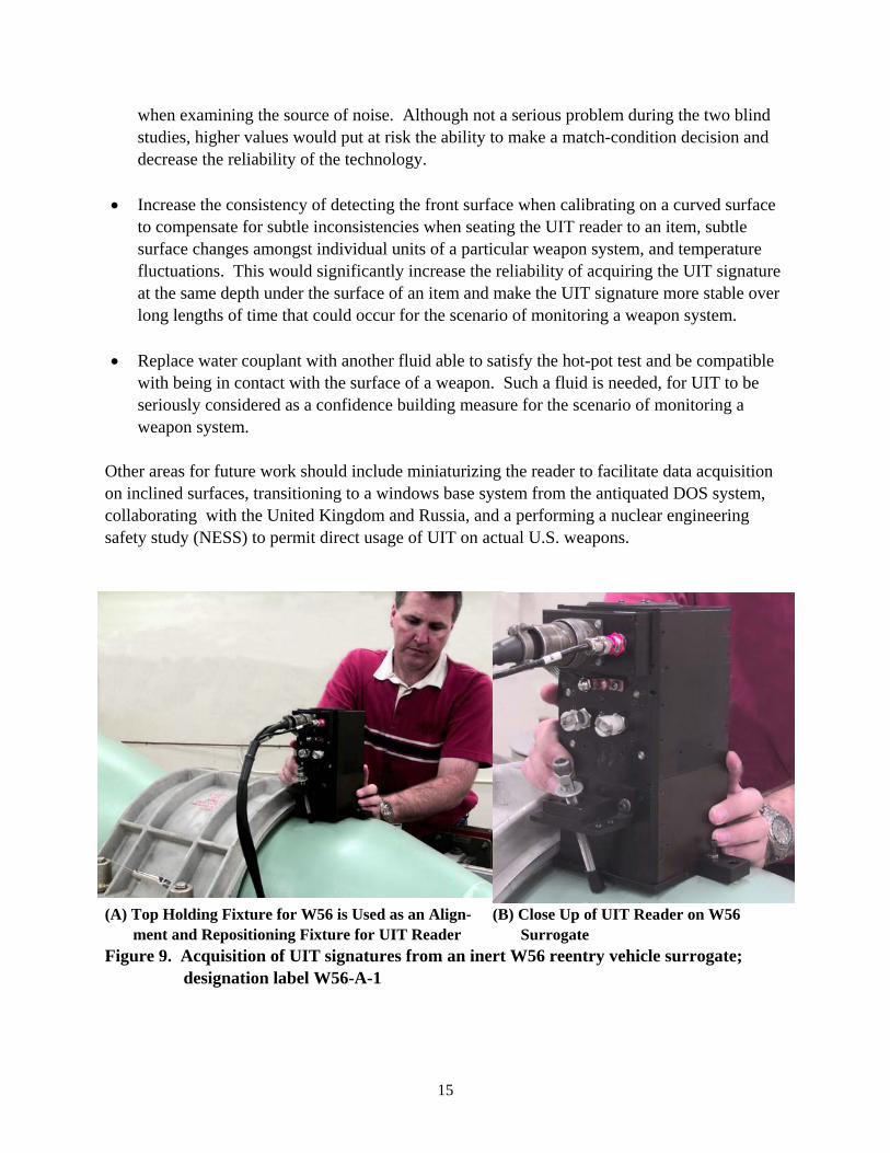
4.5 Proof-of-Concept on W56 Reentry Vehicle An attempt was made to broaden the breadth of application of using an UIT signature to uniquely identify a weapon by a proof-of-concept test on a reentry vehicle that was conveniently available at Pantex. An inert W56 trainer, designated as W56-A-1, was located in the same complex as the inert B61 surrogates. The Model UIT-5100 was hand carried and applied to an inert W56 surrogate, designation label W56-A-1 (See Figure 9). The UIT reader was repositioned several times by using the top portion of the W56 holding fixture. The UIT reader was pressed against the fixture (straightedge to straightedge) for alignment and either features or marks on the W56 or W56 fixture were used to relocate the UIT reader to the same location. Repeat scans and low scaled MSD values indicated that valid UIT signatures had been acquired and that the UIT reader could be removed and reapplied to the W56 surrogate and result in an UIT signature that was essentially identical to the reference scan. Leveling and rotational adjustment of the UIT reader was not attempted and should be done in future work when a custom UIT-W56 fixture is designed and fabricated. 5.0 Conclusions and Recommendations A high confidence exists that an ultrasonic intrinsic tag (UIT) system, such as the Model UIT-5100, is able to perform well as either a confidence building measure or an authenticating technology to assure an item is genuine. UIT signatures are intrinsic to the material; thus, external markings on an item are unnecessary. A well designed fixture is one means to

14
consistently place the UIT reader to the same location on an item to acquire meaningful UIT signatures. Two blind tests performed on a population of five inert B61 trainers indicated a high reliability to objectively identify a unique weapon item based solely on UIT Signatures. An argument could be made for the first test that the UIT operator may have had some a prior knowledge that aided in correctly identifying the selected trainer. The second test; however, was a true blind test in that independent personnel selected the trainer for the test, masked the unique identification label prior to presenting the item for evaluation, moved the selected trainer to a separate room clearly out of sight of the other B61 trainers, and witnessed the decision calls made by the UIT system. The UIT operator acquired an UIT signature and a unique match was correctly made using reference UIT signatures acquired the day before. The true blind test included 10 decisions objectively made by the computer using a scaled mean squared distance (MSD) algorithm. All 10 decisions were correct with eight non-match decisions and two match decisions.
Table 6. UIT signature validation from an inert W56 reentry vehicle, designation W56-A-1. No. File Designation File Designation Comment Scaled MSD Between
Repeat Scan Signatures 1 Pantex-2-17 Pantex-2-18 Repeat scans were
acquired without moving the reader.
0.005
2 Pantex-2-17 Pantex-2-19 Reader was removed from the item and then reapplied to the item.
0.008
3 Pantex-2-17 Pantex-2-20 Reader was removed from the item and then reapplied to the item.
0.034
UIT signatures acquired from the UIT-B61 check plate indicated that the instrument functioned well for a time period exceeding nine months that started prior to travel to Pantex to perform the experiment. Proof-of-concept for another possible weapon component, namely the W56 reentry vehicle was also successfully demonstrated by validated UIT signatures acquired from an inert W56 trainer. 6.0 Future Work Future work should address the following: • Provide a basis and correct for why the MSD values for the match condition were generally
in the 0.3 to 0.4 range and not lower such as 0.1 which is more typical of normal system operation. The higher values inferred that an unknown source of noise or variation was present while conducting the two blind tests. The study should entail a mockup such as the portion of the B61 having the lifting lugs so the effect of the positioning fixture is included
when examining the source of noise. Although not a serious problem during the two blind studies, higher values would put at risk the ability to make a match-condition decision and decrease the reliability of the technology.
• Increase the consistency of detecting the front surface when calibrating on a curved surface
to compensate for subtle inconsistencies when seating the UIT reader to an item, subtle surface changes amongst individual units of a particular weapon system, and temperature fluctuations. This would significantly increase the reliability of acquiring the UIT signature at the same depth under the surface of an item and make the UIT signature more stable over long lengths of time that could occur for the scenario of monitoring a weapon system.
• Replace water couplant with another fluid able to satisfy the hot-pot test and be compatible
with being in contact with the surface of a weapon. Such a fluid is needed, for UIT to be seriously considered as a confidence building measure for the scenario of monitoring a weapon system.
Other areas for future work should include miniaturizing the reader to facilitate data acquisition on inclined surfaces, transitioning to a windows base system from the antiquated DOS system, collaborating with the United Kingdom and Russia, and a performing a nuclear engineering safety study (NESS) to permit direct usage of UIT on actual U.S. weapons.
(A) Top Holding Fixture for W56 is Used as an Align- ment and Repositioning Fixture for UIT Reader
(B) Close Up of UIT Reader on W56 Surrogate
Figure 9. Acquisition of UIT signatures from an inert W56 reentry vehicle surrogate; designation label W56-A-1
15

16
7.0 References 1. U.S. Patent 5,454,045, 1994. Apparatus and Method for Identification and Recognition of an
Item with Ultrasonic Patterns from Item Subsurface Micro-Features. 2. Good, M. S., N. H. Hansen, P. G. Heasler, H. A. Undem, J. L. Fuller, and J. R. Skorpik.
1994. "Intrinsic Signatures of Polymer-Based, Fiber-Reinforced Composite Structures: An Ultrasonic Approach," Review of Progress in Quantitative Nondestructive Evaluation, Vol. 13, pp. 863-870. Plenum Press, New York.
3. Undem, H. A., N. H. Hansen, M. S. Good, and P. G. Heasler. 1992. "Ultrasonic Intrinsic Tag," Verification Technologies, Third Quarter 1992, DOE/DP/OAC/VT-92B, pp. 14-18. U.S. Department of Energy, Washington, D.C.
8.0 Contacts Technical contacts are provided below. 8.1 Pacific Northwest National Laboratory Contacts Morris S. Good Phone: 509-375-2529 Facsimile: 509-375-6737 e-mail: [email protected] Bret E. Simpkins Phone: 509-372-4601 Facsimile: 509-372-4316 e-mail: [email protected] Pacific Northwest National Laboratory P.O. Box 999 Richland, WA 99352 8.2 Pantex Contacts Leigh Bratcher Phone: 806-477-5366 Facsimile: 806-477-5930 e-mail: [email protected] Byron P. Burkhard Phone: 806-477-3284 Facsimile: 806-477-5930 e-mail: [email protected]
BWXT-Pantex P.O. Box 30020 Amarillo, TX 79120-0020