ultrasonic consolidation : status report on development … meeting proceedings/rto... ·...
TRANSCRIPT

Ultrasonic Consolidation : Status Report on Development of Solid State Net Shape
Processing for Direct Manufacturing
Dr. Dawn R. White Solidica, Inc.
3941 Research Park Drive, Ste. C
Ann Arbor, MI 48108 USA
ABSTRACT
Ultrasonic Consolidation is a solid state additive manufacturing process based on continuous
ultrasonic metal welding. Metal foil layers are sequentially laminated to produce net shape
objects from common engineering alloys. Most additive manufacturing processes use some form
of material phase transformation to achieve the transition from a featureless feedstock to a fit-for-
service geometry. This transformation puts practical limits on the range of materials that can be
deposited. Ultrasonic Consolidation (UC) on the other hand, achieves laminar deposition using
solid state bonding and so can be used in conjunction with a range of thermally delicate or non-
equilibrium microstructured materials. This paper documents the status of the process, and some
current and emerging applications
1.0 INTRODUCTION AND BACKGROUND
Most deposition processes use some form of material phase transformation to achieve the
transition from a featureless feedstock to fit-for-purpose engineering article. Typically this
involves a liquid-solid transformation, which puts practical limits on the range of materials that
can be deposited. Ultrasonic Consolidation (UC) on the other hand, achieves laminar deposition
using solid state bonding and so can be used in conjunction with a range of thermally delicate or
non-equilibrium microstructured materials.
Base
Rotating Sonotrode
Direction of Travel
Direction of excitation
Ultrasonic interfacialvibration
Friction at interfacebreaks up oxides
Force applied by sonotrode
Held stationary by anvilAtoms diffuse across
atomically clean interface
20 µm
True metallurgical bond formed
Base
Rotating Sonotrode
Direction of Travel
Direction of excitation
Base
Rotating Sonotrode
Direction of Travel
Direction of excitation
Ultrasonic interfacialvibration
Friction at interfacebreaks up oxides
Force applied by sonotrode
Held stationary by anvilAtoms diffuse across
atomically clean interface
20 µm
True metallurgical bond formed
Figure 1. Ultrasonic Consolidation process schematic.
The Ultrasonic Consolidation process differs substantially from other direct metal additive
manufacturing processes in that it applies the technologies of ultrasonic joining to produce true
metallurgical bonds between layers of material without generating molten metal at the interface.
RTO-MP-AVT-139 21 - 1
UNCLASSIFIED/UNLIMITED
UNCLASSIFIED/UNLIMITED
White, D.R. (2006) Ultrasonic Consolidation : Status Report on Development of Solid State Net Shape Processing for Direct Manufacturing. In Cost Effective Manufacture via Net-Shape Processing (pp. 21-1 – 21-12). Meeting Proceedings RTO-MP-AVT-139, Paper 21. Neuilly-sur-Seine, France: RTO. Available from: http://www.rto.nato.int/abstracts.asp.

UC is a micro-friction process, the mechanics of which are schematically illustrated in Figure 1.
During UC, the material being deposited is translated against the previously built volume at very
high frequency and low amplitude. As this occurs, surface contaminants such as oxides are
fractured and displaced, and atomically clean surfaces are brought into intimate contact under
modest pressures at temperatures that typically do not exceed 0.5 Tm. Plastic flow occurs in a
narrow interfacial zone about 10-20 microns in width, and recrystallization and grain growth
proceed across the interface. A strong, featureless bond zone results, without the coarse,
remelted zones characteristic of liquid phase direct metal processes. Oxides at the build material
surface, and inclusions present in the build material are broken up and distributed in the bond
zone. Figure 2 shows the microstructure across an interlaminar boundary following UC during a
part build.
Figure 2. Optical micrograph of UC bond zone. 1000X
Solid state processing has a number of important benefits in direct manufacture of metal tooling
and parts.
1. No safety hazards associated with the formation of liquid metal, metal fume, powder
handling, dust or other molten metal handling problems.
2. No atmosphere control is required to address molten metal oxidation issues.
3. Low energy consumption, due to the low temperatures involved and small volumes of
material actually affected metallurgically by the process.
4. Reduced residual stresses and distortion, because no liquid-solid transformation occurs,
and dimensional changes during processing are substantially lowered.
5. Higher deposition rate because lower heat input per deposited volume means less time is
required for heat dissipation.
6. Uniform article composition employing engineering alloys without infiltrants.
Because UC is a solid state process, it provides excellent potential as a means of fabricating
multi-material and functionally gradient armor. Table 2 below [ref AWS Handbook] shows the
material combinations that have been previously demonstrated to be suitable for use with
ultrasonic metal joining technology.
Ultrasonic Consolidation : Status Report on Development of Solid State Net Shape Processing for Direct Manufacturing
21 - 2 RTO-MP-AVT-139
UNCLASSIFIED/UNLIMITED
UNCLASSIFIED/UNLIMITED

Table 1. Ultrasonic metal joining combinations. [1]
1.1 Preliminary Properties Data
Very limited tensile data has been obtained however, for 3003 H18, our standard build material
for rapid prototyping, the following results were obtained on standard Charpy specimens using a
simple, uninstrumented testing machine.
Table 2.
Impact Results
100% laminar 50% laminar -
50% billet
6061 H-18 200 ft-lbs 197 ft-lbs
3003 H-18 173 ft-lbs 180ft-lbs
Preliminary Charpy testing has been conducted on some ultrasonically laminated specimens to
illustrate this phenomenon. Several geometries were tested, the results are given in Table 3
below.
Table 3. Charpy Specimens
Specimen type Ft-lbs result
Al Be Cu Ge Au Fe Mg Mo Ni Pd Pt Si Ag Ta Sn Ti W Zr
Al Alloys � � � � � � � � � � � � � � � � � �
Be Alloys � � � �
Cu Alloys � � � � � � � � � � � � �
Ge � �
Au � � � � � � � � � �
Fe Alloys � � � � � � � � �
Mg Alloys � � �
Mo alloys � � � � � � �
Ni Alloys � � � � � �
Pd � � �
Pt Alloys � � � � �
Si � �
Ag Alloys � � �
Ta Alloys � � �
Sn �
Ti Alloys � �
W Alloys �
Zr Alloys �
Ultrasonic Consolidation : Status Report on Development of Solid State Net Shape Processing for Direct Manufacturing
RTO-MP-AVT-139 21 - 3
UNCLASSIFIED/UNLIMITED
UNCLASSIFIED/UNLIMITED

100 % laminar 173
50% laminar,
notched laminate
180
50% laminate,
notched base
163
Further testing is clearly needed. In Solidica’s historical rapid tooling market, these data were
unimportant to the customer base. However, as applications in manufacturing and repair expand,
there is an increased need for data, which Solidica is working to fulfill.
Ultrasonic Consolidation : Status Report on Development of Solid State Net Shape Processing for Direct Manufacturing
21 - 4 RTO-MP-AVT-139
UNCLASSIFIED/UNLIMITED
UNCLASSIFIED/UNLIMITED

Ultrasonic Consolidation : Status Report on Development of Solid State Net Shape Processing for Direct Manufacturing
RTO-MP-AVT-139 21 - 5
UNCLASSIFIED/UNLIMITED
UNCLASSIFIED/UNLIMITED
2.0 Current Applications
Solidica’s initial application for UC is in the rapid prototyping and rapid tooling arena,
with a principal focus on tooling. Recently a third party study was performed with
Raytheon, Inc. on the use of UC in fabrication of tooling. These results were obtained on
fabrication of mold for producing investment casting patterns. However, they are likely
to be representative of results for aluminium tooling for vacuum casting, injection
molding and other similar processes.
2.1 Tooling Case Study Results
The UC process was developed as a rapid tooling technology that combines the benefits of
additive and subtractive machining to produce a “one button” system for fabricating tooling for
processes such as vacuum forming, injection molding, etc. that typically require multiple
machines (e.g., mills, EDM, etc.) and operators.
As a tooling process, UC embodies many principles of lean manufacturing, reducing multiple part
programs, machines, and operators to one piece flow. This is illustrated in Figure 3.
Figure 3. Conventional vs. UC process flow schematic
A third party study was conducted on time and cost savings associated with using UC to produce
aluminum tooling for producing wax patterns for investment casting. In this study, the
fabrication of UC tooling and waxes was compared to production of patterns using
stereolithography, and production of wax patterns using conventionally fabricated tooling. The

study compared SLA patterns produced at an in house facility with quotes from two outside
service bureaus, and the time/cost of producing aluminum tooling via UC with that produced by
an outside tool and die shop. Figure 4 show the tools, the patterns, and the parts produced during
this study.
Figure 4. Investment casting pattern tooling produced via UC with wax patterns and parts.
The results showed that for volumes above 15-20 parts, it was less expensive to produce
permanent aluminum tooling via UC than to produce SLA patterns. This is illustrated in Figure 5.
In addition, UC tooling was found to be very competitive in timing as well, as shown in Figure 6.
Figure 5. Cost of producing investment cast parts using various approaches
Cost by process
$0
$2,000
$4,000
$6,000
$8,000
$10,000
$12,000
$14,000
$16,000
$18,000
$20,000
20 40 80 160
part quantity
In-house SLA
SB SLA #1
SB SLA #2
Conventional Tooling
Formation™
In-house SLA
SB SLA #1
SB SLA #2
Conventional Tooling
Formation™
Ultrasonic Consolidation : Status Report on Development of Solid State Net Shape Processing for Direct Manufacturing
21 - 6 RTO-MP-AVT-139
UNCLASSIFIED/UNLIMITED
UNCLASSIFIED/UNLIMITED

Figure 6. Cost of producing investment cast parts using various approaches
3.0 Emerging Applications
As noted above, UC is a very low temperature process in comparison to other direct metal
deposition technologies such as laser and electron beam powder deposition. As a result, a
number of direct manufacturing applications are possible with this process. Some of these
include:
• Continuous Fiber Reinforced Metal Matrix Composites (CFR MMCs)
• Functionally gradient and dissimilar metals laminates for various applications
• Embedded sensors and electronics
• Embedded fibers with non-structural capabilities
These capabilities have applications as diverse as
1. Real time control of mold temperatures
2. Advanced structural materials
3. Rugged wireless sensors
4. Tamperproof enclosures for electronic devices
3.1 Composite Materials and Laminates via UC
As shown in Table 1 above, ultrasonic metal welding allows many materials that are
metallurgically compatible during liquid phase welding to be successfully joined. In UC, this
characteristic is exploited to allow unique functionally gradient materials to be fabricated. Some
examples include:
• Metal-metal laminates
• Continuously reinforced metal matrix composites
• Embedded structural ceramic reinforcements
Delivery time by process
0
5
10
15
20
25
30
35
40
45
20 40 80 160
part quantity
da
ys
Formation™
In-house SLA
SB SLA #1
SB SLA #2
Conventional Tooling
Formation™
In-house SLA
SB SLA #1
SB SLA #2
Conventional Tooling
Ultrasonic Consolidation : Status Report on Development of Solid State Net Shape Processing for Direct Manufacturing
RTO-MP-AVT-139 21 - 7
UNCLASSIFIED/UNLIMITED
UNCLASSIFIED/UNLIMITED

Metal laminates including Al-Cu, Al-Ti, Ni-Ti, and other multi-layer couples have been
produced. Figures 6 showing Al-Ti provide a good example system, as it is relatively difficult to
produce such laminates using most techniques [2].
Figure 6. Ti Al laminate produced via UC at lower and higher magnification.
Similarly, meshes can be embedded between two layers of material to increase stiffness with a
relatively small increase in weight, as illustrated in Figure 7, where a stainless steel mesh is
embedded in a 6061 Al matrix.
Figure 7. 316 stainless mess embedded in 6061 Al matrix via UC.
Although detailed studies have not been conducted, there is no evidence that a reaction occurs
between them metal matrix and the embedded fiber, or the laminate layers, even for material
couples such as Al-Ti in which such reactions are known to occur. Figure 8 below shows an
example of SiC fibers embedded in an aluminum matrix in which this was investigated. As
illustrated in Figures 8 a,b, and c below, use of EDS to map the distribution of key elements Si,
and Al following UC to embed an SiC fiber in Al, failed to show any evidence that diffusion or
reactions occurred at the interace between the Al matrix and the fiber during the embedding
process.
Ultrasonic Consolidation : Status Report on Development of Solid State Net Shape Processing for Direct Manufacturing
21 - 8 RTO-MP-AVT-139
UNCLASSIFIED/UNLIMITED
UNCLASSIFIED/UNLIMITED

Fig. 8a. SiC fiber in Al Fig. 8b. Al elemental map. Fig. 8c. Si elemental map
Ultrasonic Consolidation : Status Report on Development of Solid State Net Shape Processing for Direct Manufacturing
RTO-MP-AVT-139 21 - 9
UNCLASSIFIED/UNLIMITED
UNCLASSIFIED/UNLIMITED
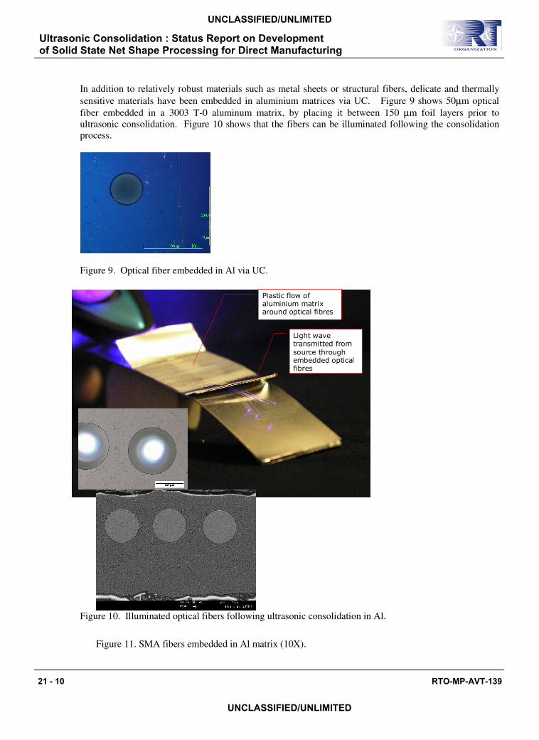
In addition to relatively robust materials such as metal sheets or structural fibers, delicate and thermally
sensitive materials have been embedded in aluminium matrices via UC. Figure 9 shows 50µm optical
fiber embedded in a 3003 T-0 aluminum matrix, by placing it between 150 µm foil layers prior to
ultrasonic consolidation. Figure 10 shows that the fibers can be illuminated following the consolidation
process.
Figure 9. Optical fiber embedded in Al via UC.
Figure 10. Illuminated optical fibers following ultrasonic consolidation in Al.
Figure 11. SMA fibers embedded in Al matrix (10X).
Plastic flow of aluminium matrix around optical fibres
Light wave transmitted from
source through embedded optical fibres
Plastic flow of aluminium matrix around optical fibres
Light wave transmitted from
source through embedded optical fibres
Ultrasonic Consolidation : Status Report on Development of Solid State Net Shape Processing for Direct Manufacturing
21 - 10 RTO-MP-AVT-139
UNCLASSIFIED/UNLIMITED
UNCLASSIFIED/UNLIMITED
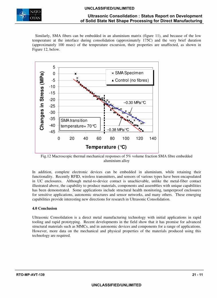
Similarly, SMA fibers can be embedded in an aluminium matrix (figure 11), and because of the low
temperature at the interface during consolidation (approximately 175C) and the very brief duration
(approximately 100 msec) of the temperature excursion, their properties are unaffected, as shown in
Figure 12, below.
Fig.12 Macroscopic thermal mechanical responses of 5% volume fraction SMA fibre embedded
aluminium alloy
In addition, complete electronic devices can be embedded in aluminium, while retaining their
functionality. Recently RFID, wireless transmitters, and sensors of various types have been encapsulated
in UC enclosures. Although metal-to-device contact is unachievable, unlike the metal-fiber contact
illustrated above, the capability to produce materials, components and assemblies with unique capabilities has been demonstrated. Some applications include structural health monitoring, tamperproof enclosures
for sensitive applications, autonomic structures and sensor networks, and many others. These emerging
capabilities provide interesting new directions for research in Ultrasonic Consolidation.
4.0 Conclusion
Ultrasonic Consolidation is a direct metal manufacturing technology with initial applications in rapid
tooling and rapid prototyping. Recent developments in the field show that it has promise for advanced
structural materials such as MMCs, and in autonomic devices and components for a range of applications.
However, more data on the mechanical and physical properties of the materials produced using this
technology are required.
-45
-40
-35
-30
-25
-20
-15
-10
-5
0
5
0 20 40 60 80 100 120 140
Temperature (°C)
Ch
an
ge
s i
n S
tre
ss
(M
Pa
) SMA Specimen
Control (no fibres)
–0.30 MPa/°C
–0.38 MPa/°C
SMA transition
temperature= 70°C
Ultrasonic Consolidation : Status Report on Development of Solid State Net Shape Processing for Direct Manufacturing
RTO-MP-AVT-139 21 - 11
UNCLASSIFIED/UNLIMITED
UNCLASSIFIED/UNLIMITED

Ultrasonic Consolidation : Status Report on Development of Solid State Net Shape Processing for Direct Manufacturing
21 - 12 RTO-MP-AVT-139
UNCLASSIFIED/UNLIMITED
UNCLASSIFIED/UNLIMITED
MEETING DISCUSSION – PAPER NO: 21
Author: D. White
Discusser: L. Pambaguian
Question: How easy is it to procure the tape you use? Do you have specific requirements with respect to the procurement?
Response: Feedstock can be procured from foil re-rollers on a convenient basis. Certain dimensional accuracy and surface condition requirements must be met.
Discusser: P. Brown
Question: Can your technique be used to bond metal/composite materials and steels?
Response: I think it is possible - preliminary observations with polymer based composites would indicate that this is the case, but no detailed experiments have been performed.
Discusser: D. Dicus
Question: How are Al tooling applications impacted by the poor transverse bonding in your laminates?
Response: Tooling is generally bonded in compression + shear. Tests of our molds using glass filled polymers have failed to produce shear failures in the molds.
Discusser: J. Savoie
Question: 1. Have you performed shear tests? 2. In case use of annealed sheet, the bounded zone experienced plastic deformation while the core is un-deformed. After final annealing, what would be the grain size distribution?
Response: 1. Shear tests have been performed in a long transverse testing where results are dominated by tape geometry and incomplete tape-tape welds in “Z” axis. No sheet shear tests have been performed. 2. I have not performed such a test and don’t know what effect might be.