ultrapure water for srf applicationsultrapure water for srf applications tony reilly . uspas:...
TRANSCRIPT

T. Reilly
Ultrapure Water for SRF Applications
Tony Reilly USPAS: Ultrapure Water: Overview and Application January 2015
T. Reilly USPAS SRF Course Jan. 2015 2
Objective
• Provide a basic understanding of Ultrapure Water (UPW) systems – Subsystems, primary unit operations – Design guidelines – Performance monitoring – Troubleshooting
• Provide useful information to enable you to better communicate and engage with those more involved with UPW systems – “Enough information to be dangerous”
USPAS SRF Course Jan. 2015 2 /151
T. Reilly USPAS SRF Course Jan. 2015 3
Outline • Importance and application of ultrapure water
(UPW) in SRF • How to make UPW – System fundamentals • Materials used in UPW systems • Monitoring UPW systems
– Online and off-line analytical • Troubleshooting quality issues • Brief look at hot UPW systems • Overview of Jefferson Lab’s UPW system • System Tour (time pending)
USPAS SRF Course Jan. 2015
T. Reilly USPAS SRF Course Jan. 2015 4
Why is UPW Important
• UPW is used extensively in the making of SRF cavities – Fabrication, chemical surface polishing,
component cleaning, and final rinsing – Every RF surface is exposed to UPW – High quality UPW contributes to high
performing SRF cavities – The use of UPW is part of the approach to
eliminating field emission
USPAS SRF Course Jan. 2015
T. Reilly USPAS SRF Course Jan. 2015 5
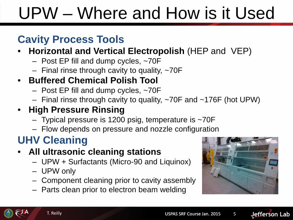
UPW – Where and How is it Used Cavity Process Tools • Horizontal and Vertical Electropolish (HEP and VEP)
– Post EP fill and dump cycles, ~70F – Final rinse through cavity to quality, ~70F
• Buffered Chemical Polish Tool – Post EP fill and dump cycles, ~70F – Final rinse through cavity to quality, ~70F and ~176F (hot UPW)
• High Pressure Rinsing – Typical pressure is 1200 psig, temperature is ~70F – Flow depends on pressure and nozzle configuration
UHV Cleaning • All ultrasonic cleaning stations
– UPW + Surfactants (Micro-90 and Liquinox) – UPW only – Component cleaning prior to cavity assembly – Parts clean prior to electron beam welding
USPAS SRF Course Jan. 2015

T. Reilly USPAS SRF Course Jan. 2015 6
What is Ultrapure Water General Description • Water that is devoid of all dissolved, suspended, organic and
inorganic impurities • Reality is the water is not 100% completely devoid of all
impurities • Devoid to the detection limits of analytical methods used to
quantify the quality • Detection limits are often expressed in
• PPM: Parts per Million (mg/L) • PPB: Parts per Billion (µg/L) – Most relevant for SRF applications • PPT: Parts per Trillion (ng/L) • PPQ: Parts per quadrillion (pg/ml)
More meaningful definition • Water that has been purified to a specific standard or quality specification • As many definitions as there are specifications
USPAS SRF Course Jan. 2015
1 ppb is roughly the equivalent of one drop in 250 chemical drums
T. Reilly
Typical Ultrapure Water System Fundamentals
with References to Jefferson Lab’s UPW System
USPAS SRF Course Jan. 2015
T. Reilly USPAS SRF Course Jan. 2015 8
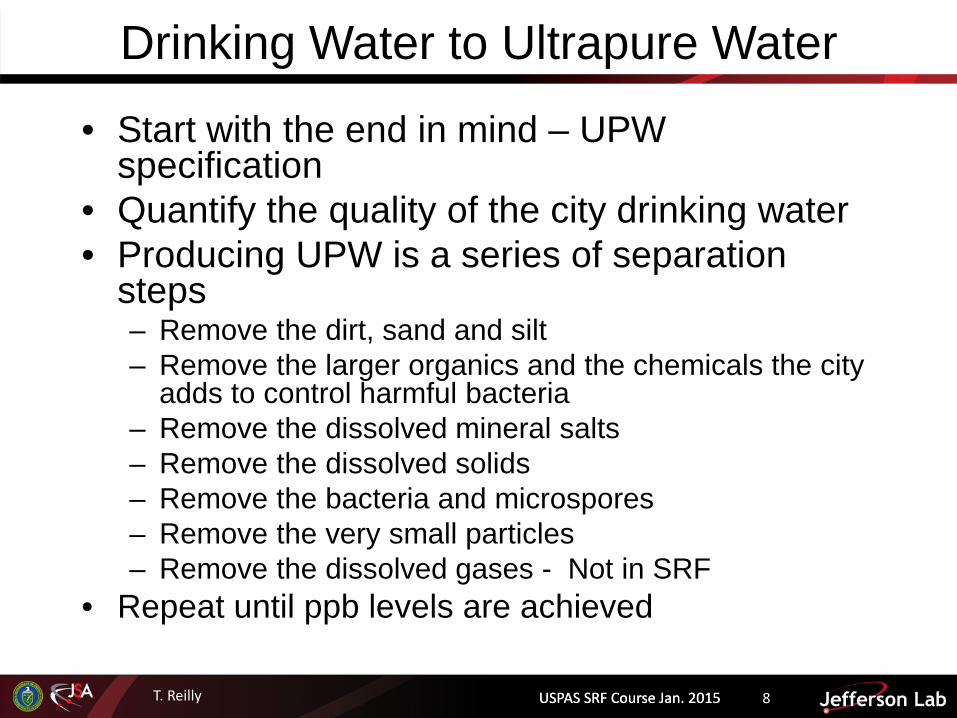
Drinking Water to Ultrapure Water
• Start with the end in mind – UPW specification
• Quantify the quality of the city drinking water • Producing UPW is a series of separation
steps – Remove the dirt, sand and silt – Remove the larger organics and the chemicals the city
adds to control harmful bacteria – Remove the dissolved mineral salts – Remove the dissolved solids – Remove the bacteria and microspores – Remove the very small particles – Remove the dissolved gases - Not in SRF
• Repeat until ppb levels are achieved
USPAS SRF Course Jan. 2015

T. Reilly USPAS SRF Course Jan. 2015 9
Ultrapure Water Specification In the US, the most widely used requirements for UPW quality for microelectronics/semiconductor are documented by
– American Society for Testing and Materials International (ASTM) D5127 "Standard Guide for Ultra-Pure Water Used in the Electronics and Semiconductor Industries“
– Semiconductor Equipment and Materials International (SEMI F63) "Guide for ultrapure water used in semiconductor processing“
ASTM D5127 (2007) Other industry specifications include: • Electric Power Research Institute (EPRI) (power) • American Society of Mechanical Engineers(ASME) (power) • International Association for the Properties of Water and Steam (IAPWS)
(power). • Pharmaceutical plants follow water quality standards as developed by the
United States Pharmacopeia
USPAS SRF Course Jan. 2015
T. Reilly USPAS SRF Course Jan. 2015 10
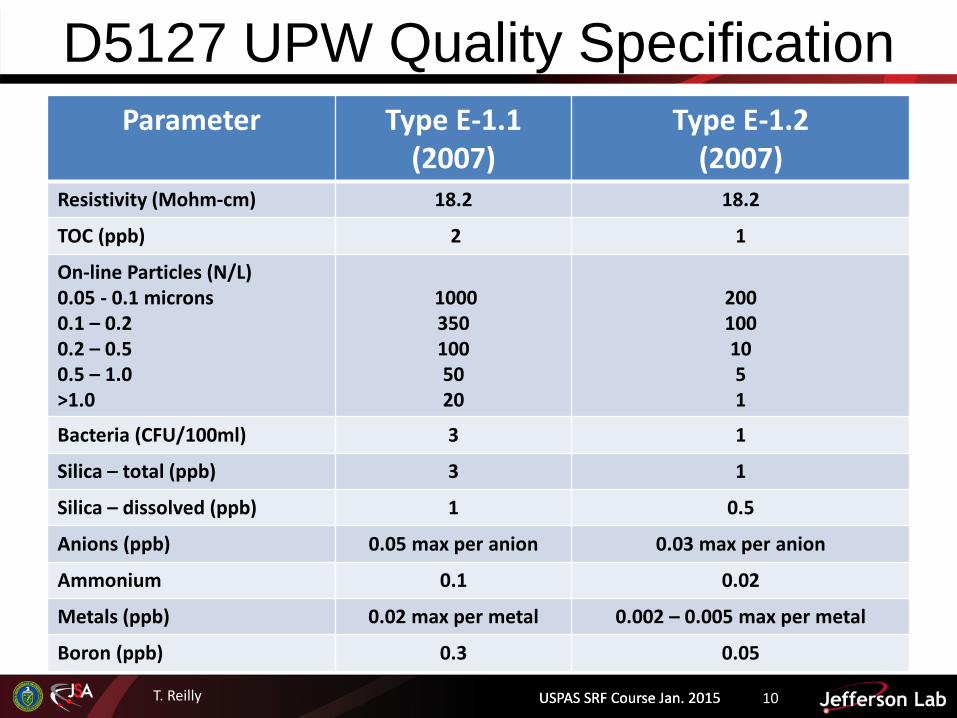
D5127 UPW Quality Specification Parameter Type E-1.1
(2007) Type E-1.2
(2007) Resistivity (Mohm-cm) 18.2 18.2
TOC (ppb) 2 1
On-line Particles (N/L) 0.05 - 0.1 microns 0.1 – 0.2 0.2 – 0.5 0.5 – 1.0 >1.0
1000 350 100 50 20
200 100 10 5 1
Bacteria (CFU/100ml) 3 1
Silica – total (ppb) 3 1
Silica – dissolved (ppb) 1 0.5
Anions (ppb) 0.05 max per anion 0.03 max per anion
Ammonium 0.1 0.02
Metals (ppb) 0.02 max per metal 0.002 – 0.005 max per metal
Boron (ppb) 0.3 0.05
USPAS SRF Course Jan. 2015
T. Reilly
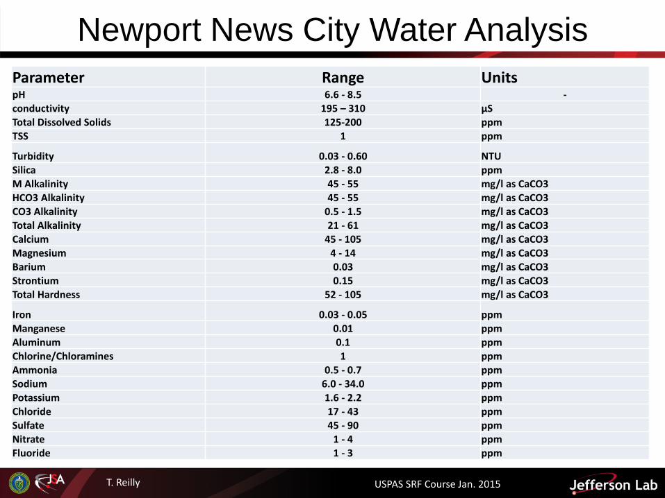
Newport News City Water Analysis
USPAS SRF Course Jan. 2015
Parameter Range Units pH 6.6 - 8.5 - conductivity 195 – 310 μS Total Dissolved Solids 125-200 ppm TSS 1 ppm
Turbidity 0.03 - 0.60 NTU Silica 2.8 - 8.0 ppm M Alkalinity 45 - 55 mg/l as CaCO3 HCO3 Alkalinity 45 - 55 mg/l as CaCO3 CO3 Alkalinity 0.5 - 1.5 mg/l as CaCO3 Total Alkalinity 21 - 61 mg/l as CaCO3 Calcium 45 - 105 mg/l as CaCO3 Magnesium 4 - 14 mg/l as CaCO3 Barium 0.03 mg/l as CaCO3 Strontium 0.15 mg/l as CaCO3 Total Hardness 52 - 105 mg/l as CaCO3
Iron 0.03 - 0.05 ppm Manganese 0.01 ppm Aluminum 0.1 ppm Chlorine/Chloramines 1 ppm Ammonia 0.5 - 0.7 ppm Sodium 6.0 - 34.0 ppm Potassium 1.6 - 2.2 ppm Chloride 17 - 43 ppm Sulfate 45 - 90 ppm Nitrate 1 - 4 ppm Fluoride 1 - 3 ppm
T. Reilly
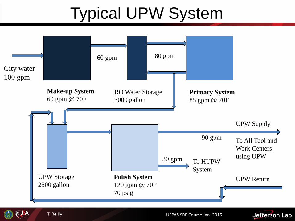
Typical UPW System
City water 100 gpm
Make-up System 60 gpm @ 70F
RO Water Storage 3000 gallon
Primary System 85 gpm @ 70F
60 gpm 80 gpm
Polish System 120 gpm @ 70F 70 psig
UPW Storage 2500 gallon
To All Tool and Work Centers using UPW
UPW Return
UPW Supply
90 gpm
To HUPW System
30 gpm
USPAS SRF Course Jan. 2015
T. Reilly USPAS SRF Course Jan. 2015 13
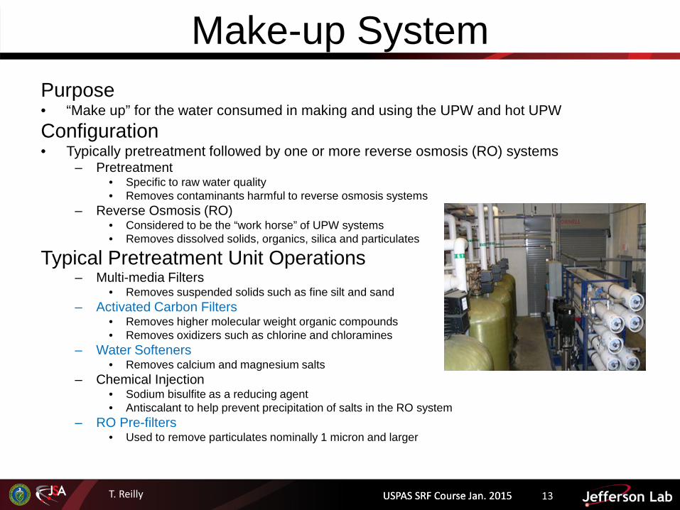
Make-up System Purpose • “Make up” for the water consumed in making and using the UPW and hot UPW Configuration • Typically pretreatment followed by one or more reverse osmosis (RO) systems
– Pretreatment • Specific to raw water quality • Removes contaminants harmful to reverse osmosis systems
– Reverse Osmosis (RO) • Considered to be the “work horse” of UPW systems • Removes dissolved solids, organics, silica and particulates
Typical Pretreatment Unit Operations – Multi-media Filters
• Removes suspended solids such as fine silt and sand – Activated Carbon Filters
• Removes higher molecular weight organic compounds • Removes oxidizers such as chlorine and chloramines
– Water Softeners • Removes calcium and magnesium salts
– Chemical Injection • Sodium bisulfite as a reducing agent • Antiscalant to help prevent precipitation of salts in the RO system
– RO Pre-filters • Used to remove particulates nominally 1 micron and larger
USPAS SRF Course Jan. 2015

T. Reilly
Typical UPW Make-up System City water
NaOH Injection
Activated Carbon Filters • Large organics • Oxidizers
Water Softeners • Mineral salts
Heat Exchanger • Heats to 70F
110 gpm
30 gpm to recovery
1st Pass RO
10 gpm to Boilers
100 gpm
2nd Pass RO
85 gpm
115 gpm
15 gpm
Suspended and dissolved solids , organics
JLab
USPAS SRF Course Jan. 2015
T. Reilly USPAS SRF Course Jan. 2015 15
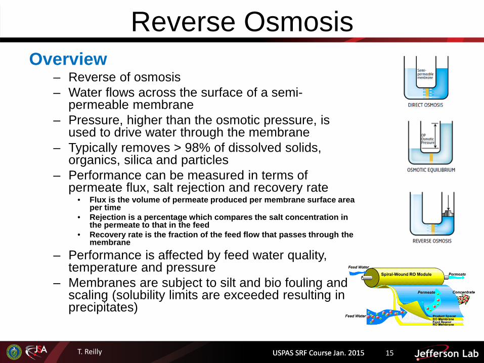
Reverse Osmosis Overview
– Reverse of osmosis – Water flows across the surface of a semi-
permeable membrane – Pressure, higher than the osmotic pressure, is
used to drive water through the membrane – Typically removes > 98% of dissolved solids,
organics, silica and particles – Performance can be measured in terms of
permeate flux, salt rejection and recovery rate • Flux is the volume of permeate produced per membrane surface area
per time • Rejection is a percentage which compares the salt concentration in
the permeate to that in the feed • Recovery rate is the fraction of the feed flow that passes through the
membrane
– Performance is affected by feed water quality, temperature and pressure
– Membranes are subject to silt and bio fouling and scaling (solubility limits are exceeded resulting in precipitates)
USPAS SRF Course Jan. 2015
T. Reilly
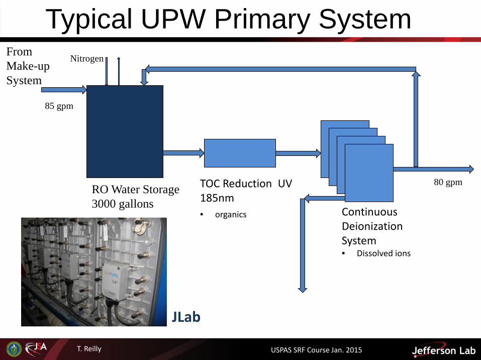
Typical UPW Primary System From Make-up System
RO Water Storage 3000 gallons
Nitrogen
TOC Reduction UV 185nm • organics Continuous
Deionization System • Dissolved ions
85 gpm
80 gpm
5 gpm to waste
JLab
USPAS SRF Course Jan. 2015
T. Reilly USPAS SRF Course Jan. 2015 17
UPW Primary System Purpose • Serves as the “primary” deionization stage • Further reduce dissolved ions and organics Configuration • Typically flows in a loop starting from RO permeate storage tank
through organic oxidizers followed by ion exchange then back to RO storage
Typical Primary Unit Operations • Ultraviolet oxidation
– 185 nm wavelength • Ion exchange
– Mixed bed, containing both anion and cation exchange resin in same unit – Electrodeionization (EDI) (a.k.a continuous deionization (CDI) )
• Ultraviolet sterilizer – 254nm wavelength
• Water is sent to UPW storage tank in Polish system as needed, triggered by water level in UPW tank
USPAS SRF Course Jan. 2015

T. Reilly USPAS SRF Course Jan. 2015 18
UPW Primary System Photolytic Oxidation • Uses 185nm ultraviolet light • Oxidation occurs by direct UV absorption and through production of
hydroxyl radicals • Generally, organics are broken down to CO2 + H2O
Ion Exchange • Cation resin in the H+ form
– H+ is exchanged for cations – R’H + Na+ R’Na + H+
• Anion resin in the OH- form – OH- is exchanged for anions – R’’OH + Cl- R’’Cl + OH-
• H+ and OH- combine to form H2O • Process is reversible
• Resin is regenerated back to original form using strong acid and base
USPAS SRF Course Jan. 2015
T. Reilly USPAS SRF Course Jan. 2015 19
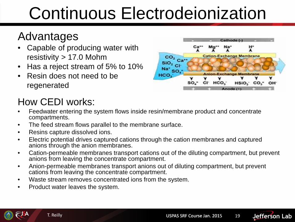
Continuous Electrodeionization
How CEDI works: • Feedwater entering the system flows inside resin/membrane product and concentrate
compartments. • The feed stream flows parallel to the membrane surface. • Resins capture dissolved ions. • Electric potential drives captured cations through the cation membranes and captured
anions through the anion membranes. • Cation-permeable membranes transport cations out of the diluting compartment, but prevent
anions from leaving the concentrate compartment. • Anion-permeable membranes transport anions out of diluting compartment, but prevent
cations from leaving the concentrate compartment. • Waste stream removes concentrated ions from the system. • Product water leaves the system.
USPAS SRF Course Jan. 2015
Advantages • Capable of producing water with
resistivity > 17.0 Mohm • Has a reject stream of 5% to 10% • Resin does not need to be
regenerated

T. Reilly
Electrodeionization
USPAS SRF Course Jan. 2015
T. Reilly USPAS SRF Course Jan. 2015 21
UPW Polish System Purpose • “Polishes” water to final quality, including temperature and pressure • Further reduce dissolved ions, organics, particles and bacteria Configuration • Typically flows in a loop starting from UPW storage tank through polish
system, out to distribution and return to UPW tank Typical Polish Unit Operations • Ultraviolet oxidation
– 185 nm wavelength • Ion exchange
– Mixed bed, containing both anion and cation exchange resin in same unit – Electrodeionization (EDI) (a.k.a continuous deionization (CDI) )
• Ultraviolet sterilizer – 254nm wavelength
• Particulate Filtration – Pleated cartridge or Ultrafiltration (UF)
• Water is sent to UPW storage tank in Polish system
USPAS SRF Course Jan. 2015

T. Reilly
Typical UPW Polish System
High Purity Ion Exchange Lead/Lag banks
UPW Storage 2500 gallons
Nitrogen
TOC Reduction UV 185nm
Heat Exchanger • Cools to 70 F +/- 2
From Primary System
80 gpm
120 gpm
Pre-Final Filters 0.1 micron
Final Filters 0.02 micron
UPW Supply
UPW Return
120 gpm
90 gpm 70 psig
30 gpm
To HUPW System
HUPW Return
Sterilizer UV 254 nm
JLab
USPAS SRF Course Jan. 2015
T. Reilly USPAS SRF Course Jan. 2015 23
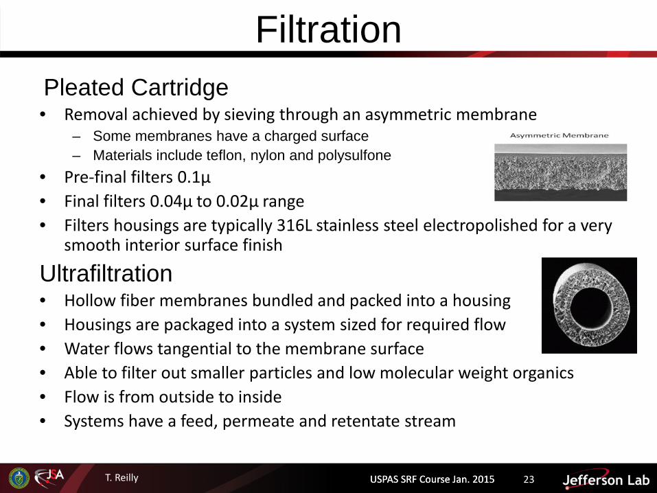
Filtration Pleated Cartridge • Removal achieved by sieving through an asymmetric membrane
– Some membranes have a charged surface – Materials include teflon, nylon and polysulfone
• Pre-final filters 0.1µ • Final filters 0.04µ to 0.02µ range • Filters housings are typically 316L stainless steel electropolished for a very
smooth interior surface finish
Ultrafiltration • Hollow fiber membranes bundled and packed into a housing • Housings are packaged into a system sized for required flow • Water flows tangential to the membrane surface • Able to filter out smaller particles and low molecular weight organics • Flow is from outside to inside • Systems have a feed, permeate and retentate stream
USPAS SRF Course Jan. 2015

T. Reilly USPAS SRF Course Jan. 2015 24
Polish Ion Exchange • Resin type should be selected
specifically for UPW, low TOC ($$)
• Very clean as indicated by superior rinse up characteristics
• Mixed bed in the H+/OH- form • Use virgin resin only
– No regeneration • Lead-lag operation is preferred
– One pass requires inlet to be high resistivity (>18 Mohm)
• Change resin ahead of breakthrough
USPAS SRF Course Jan. 2015
Representative breakthrough curve for ion exchange
Boron? Silica?

T. Reilly
UPW Distribution and System Materials of Construction
USPAS SRF Course Jan. 2015

T. Reilly USPAS SRF Course Jan. 2015 26
UPW Distribution System Sizing
– Continuously flowing in a temperature and pressure controlled loop – Supply and return piping with a back pressure control station at the end of
supply – Loop flow can be determined using 1.8 x average total consumption
• Used to accommodate peak demand and maintain proper velocities • Supply Piping
– Turbulent flow to minimize growth of biofilm – Minimum of 4 fps is frequently used as a rule of thumb – Better to use Reynolds number to minimize pipe diameter
• Return Piping – Minimum of 0.5 fps – Minimize pressure loss on flow
• Laterals and Feed Lines to Tools – Must also flow in a loop with supply and return – Keep pressure drops to less than 2 psig per 100 feet
USPAS SRF Course Jan. 2015
Tool
Supply
Return
Dead Leg?

T. Reilly USPAS SRF Course Jan. 2015 27
Dead Legs Dead Legs are one of the villains of a properly designed ultrapure water distribution system • “Dead Leg” refers to a stagnant zone of water • Occurs any place in the system where there is no flow or very little flow for a
pipe length equal to or greater than 4 to 6 pipe diameters • Most often occurs at branch valves and tool connections • Promote bacteria growth
Means to avoid • Keep any section that will experience no flow to less than 4-6 pipe dia. • Use “zero dead-leg” valves • Install by-pass flows around pumps and control valves • Install “trickle flow” paths to provide continuous flow
– Wand head on the HPR is one example
USPAS SRF Course Jan. 2015

T. Reilly USPAS SRF Course Jan. 2015 28
Materials of Construction
General Guideline for Material Selection • Wetted components that have smooth, non-porous
surfaces • Joining methods for piping and lining that minimize
crevices and discontinuities • Joining methods that minimize or eliminate the use
of glues or solvents capable of migration into the water
• Materials that are free of biological degradable substances that can be nutrient sources
• Materials should not contain leachable additives, such as pigments
USPAS SRF Course Jan. 2015

T. Reilly USPAS SRF Course Jan. 2015 29
Piping System Materials and Valves Make-up System • Piping
– Up stream of the RO system • Clean Schedule 80 PVC, solvent joints • PFA, FEP tubing, compression • EPDM (ethylene propylene diene
terpolymer) gaskets
– Down stream of the RO system • No PVC after the RO system • Polypropylene, fused • DuPont™ Viton®
• Valves – Up stream of the RO system
• Sizes 3” or less use ball or diaphragm valves
• Sizes greater than 3” use butterfly valves
– Down stream of the RO system • Do not use ball valves, only diaphragm
or butterfly based on size criteria
USPAS SRF Course Jan. 2015
Primary System • Piping
– Up stream of the Ion Exchange system
• Polypropylene, fused • PFA, FEP tubing, compression • DuPont™ Viton®
– Down stream of the Ion Exchange system
• Polypropylene, fused • Polyvinylidene fluoride (PVDF) preferred, IR
fused • PTFE (Teflon) encapsulated Viton
• Valves – Up stream of the Ion Exchange
system • Sizes 3” or less use diaphragm valves • Sizes greater than 3” use butterfly valves
– Down stream of the Ion exchange system
• Use high purity diaphragm and butterfly valves only
• Polypropylene or Teflon lined valves
T. Reilly USPAS SRF Course Jan. 2015 30
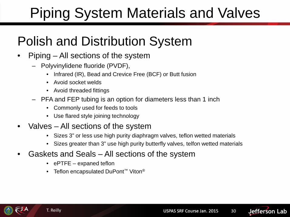
Piping System Materials and Valves
Polish and Distribution System • Piping – All sections of the system
– Polyvinylidene fluoride (PVDF), • Infrared (IR), Bead and Crevice Free (BCF) or Butt fusion • Avoid socket welds • Avoid threaded fittings
– PFA and FEP tubing is an option for diameters less than 1 inch • Commonly used for feeds to tools • Use flared style joining technology
• Valves – All sections of the system • Sizes 3” or less use high purity diaphragm valves, teflon wetted materials • Sizes greater than 3” use high purity butterfly valves, telfon wetted materials
• Gaskets and Seals – All sections of the system • ePTFE – expaned teflon • Teflon encapsulated DuPont™ Viton®
USPAS SRF Course Jan. 2015
T. Reilly
Monitoring Quality of UPW Systems
USPAS SRF Course Jan. 2015
T. Reilly USPAS SRF Course Jan. 2015 32
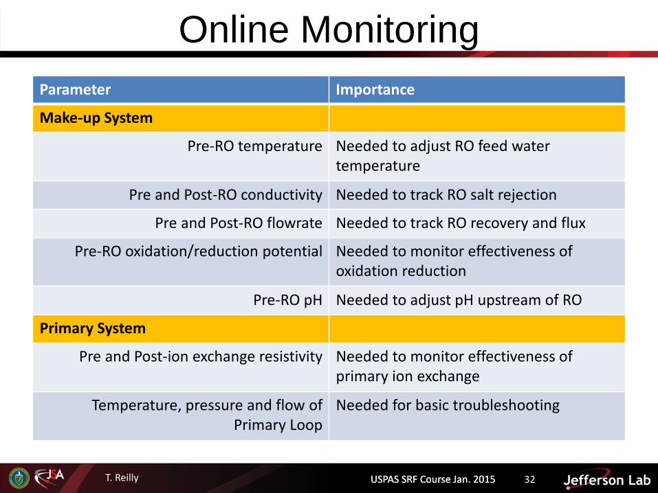
Online Monitoring Parameter Importance
Make-up System
Pre-RO temperature Needed to adjust RO feed water temperature
Pre and Post-RO conductivity Needed to track RO salt rejection
Pre and Post-RO flowrate Needed to track RO recovery and flux
Pre-RO oxidation/reduction potential Needed to monitor effectiveness of oxidation reduction
Pre-RO pH Needed to adjust pH upstream of RO
Primary System
Pre and Post-ion exchange resistivity Needed to monitor effectiveness of primary ion exchange
Temperature, pressure and flow of Primary Loop
Needed for basic troubleshooting
USPAS SRF Course Jan. 2015

T. Reilly USPAS SRF Course Jan. 2015 33
Online Monitoring Parameter Importance
Polish System Pre and Post-polish ion exchange resistivity Needed to monitor effectiveness of polish ion
exchange
Temperature, pressure and flow Needed for basic troubleshooting
UPW Supply (post-polish system)
Temperature Needed to track and adjust UPW supply temperature
Resistivity Needed to track supply quality
TOC Needed to track supply quality
Silica Needed as an indicator of ion exchange leakage
Particles Needed to track supply quality and effectiveness of final filters
Pressure at end of Supply Needed to monitor supply pressure
USPAS SRF Course Jan. 2015
Use of a data historian is recommended to retain and display key online quality parameters

T. Reilly
UPW Resistivity and TOC Trend
TOC Spec = < 2.0 ppb
Resistivity Spec = >18.2 Mohm-cm
USPAS SRF Course Jan. 2015

T. Reilly
UPW Particle Trend Chart
0.05u to 0.10u Limit = 1000 cts/L
0.10u to 0.15u Limit = 350 cts/L
0.15u to 0.2u Limit = 350 cts/L
> 0.2u Limit = 100 cts/L
USPAS SRF Course Jan. 2015
T. Reilly USPAS SRF Course Jan. 2015 36
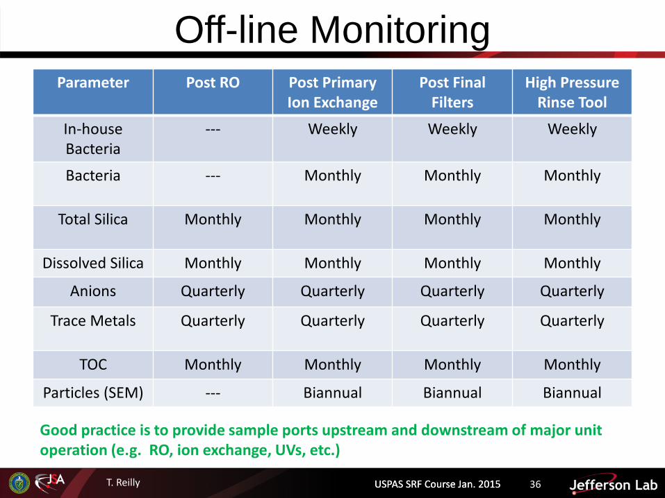
Off-line Monitoring Parameter Post RO Post Primary
Ion Exchange Post Final
Filters High Pressure
Rinse Tool
In-house Bacteria
--- Weekly Weekly Weekly
Bacteria --- Monthly Monthly Monthly
Total Silica Monthly Monthly Monthly Monthly
Dissolved Silica Monthly Monthly Monthly Monthly
Anions Quarterly Quarterly Quarterly Quarterly
Trace Metals Quarterly Quarterly Quarterly Quarterly
TOC Monthly Monthly Monthly Monthly
Particles (SEM) --- Biannual Biannual Biannual
USPAS SRF Course Jan. 2015
Good practice is to provide sample ports upstream and downstream of major unit operation (e.g. RO, ion exchange, UVs, etc.)

T. Reilly
Troubleshooting UPW Systems Basics
USPAS SRF Course Jan. 2015
T. Reilly USPAS SRF Course Jan. 2015 38
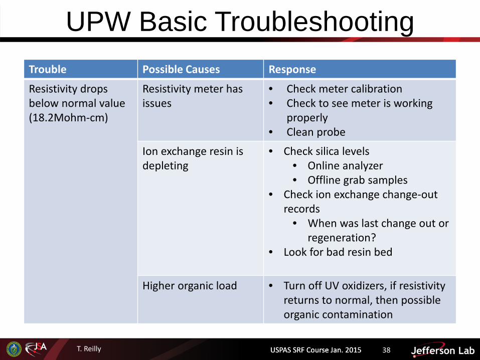
UPW Basic Troubleshooting Trouble Possible Causes Response
Resistivity drops below normal value (18.2Mohm-cm)
Resistivity meter has issues
• Check meter calibration • Check to see meter is working
properly • Clean probe
Ion exchange resin is depleting
• Check silica levels • Online analyzer • Offline grab samples
• Check ion exchange change-out records
• When was last change out or regeneration?
• Look for bad resin bed
Higher organic load • Turn off UV oxidizers, if resistivity returns to normal, then possible organic contamination
USPAS SRF Course Jan. 2015

T. Reilly USPAS SRF Course Jan. 2015 39
UPW Basic Troubleshooting Trouble Possible Causes Response
TOC has increased above normal
TOC analyzer is not working properly
• Check against another analyzer if available
• Check meter calibration • Check TOC levels offline via grab
samples
UV Oxidizer performance is degrading
• Check irradiance meter on UV unit
• Replace bulbs if low • Inspect quartz sleeves for
discoloration • Replace as needed
Higher organic load • Verify RO system is working properly
• Check conductivity of permeate, compare to normal
• If high, check each vessel
USPAS SRF Course Jan. 2015

T. Reilly USPAS SRF Course Jan. 2015 40
UPW Basic Troubleshooting Trouble Possible Causes Response
Bacteria counts are higher than normal
Sample port is contaminated
• Clean sample port with IPA, then flush and exercise valve
• If high count persist, and other locations are clean, replace sample valve
Dead leg • Check sample valve and piping system for sections of no flow or slow flow.
• Eliminate dead leg (open valve, add a bleed flow)
• Increase velocity by reducing pipe diameter
254nm UV lamp performance has deteriorated
• Check irradiance meter on UV unit
• Inspect quartz sleeves for discoloration
• Test before and after UV
USPAS SRF Course Jan. 2015
T. Reilly USPAS SRF Course Jan. 2015 41
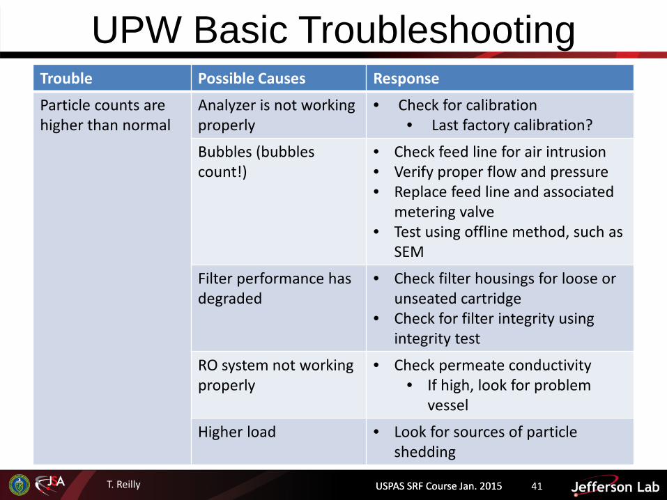
UPW Basic Troubleshooting Trouble Possible Causes Response
Particle counts are higher than normal
Analyzer is not working properly
• Check for calibration • Last factory calibration?
Bubbles (bubbles count!)
• Check feed line for air intrusion • Verify proper flow and pressure • Replace feed line and associated
metering valve • Test using offline method, such as
SEM
Filter performance has degraded
• Check filter housings for loose or unseated cartridge
• Check for filter integrity using integrity test
RO system not working properly
• Check permeate conductivity • If high, look for problem
vessel
Higher load • Look for sources of particle shedding
USPAS SRF Course Jan. 2015

T. Reilly
Hot UPW Systems (HUPW)
USPAS SRF Course Jan. 2015

T. Reilly USPAS SRF Course Jan. 2015 43
HUPW System Purpose • Hot UPW is reportedly more effective in some cleaning applications
particularly those involving viscous acids – Currently: Buffered Chemical Polish – Future: Electropolish (sulfuric acid)
Configuration • Fed from ambient UPW system • Heats water to specified temperature – 80C
Configuration • High Capacity
– Heat recovery heat exchange: Recovers heat from HUPW return – Hot water heat exchanger: Uses hot water to heat UPW to specified temperature (80C) – Ultrafiltration: Removes added particles from pumps and heat exchangers
• Point of Use – Packaged electrical heaters, teflon wetted components, high electrical loads
USPAS SRF Course Jan. 2015
T. Reilly
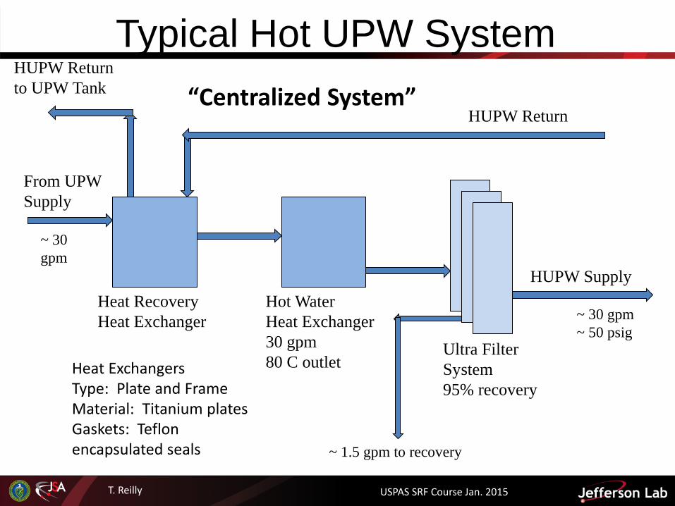
Typical Hot UPW System HUPW Return to UPW Tank
Heat Recovery Heat Exchanger
HUPW Return
From UPW Supply
~ 30 gpm
Hot Water Heat Exchanger 30 gpm 80 C outlet
Ultra Filter System 95% recovery
HUPW Supply
~ 30 gpm ~ 50 psig
~ 1.5 gpm to recovery
Heat Exchangers Type: Plate and Frame Material: Titanium plates Gaskets: Teflon encapsulated seals
“Centralized System”
USPAS SRF Course Jan. 2015
T. Reilly
Jefferson Lab’s UPW System Performance
USPAS SRF Course Jan. 2015

T. Reilly USPAS SRF Course Jan. 2015 46
Ultrapure Water Systems Main UPW System • Microelectronic Type E-1.1
> 18.2 Mohm/cm2, < 2 ppb TOC, < 2 ppb silica, < 1ppb all other ions • 60 gpm (227 liters/min) make-up capacity to loop (shared with HUPW) • 90 gpm (340 liters/min) polish loop • Provides water to the HPR, BCP, HEP, VEP tools • Provides water to all chemistry rooms • ~ 50 psig Nominal (55 psig measured) Centralized Hot UPW System • 20 gpm (76 liters/min) make-up capacity to loop • 30 gpm (114 liters/min) polish loop • ~ 50 psig Nominal • 80 C (176 F)
• Primary RO Storage: 11360 Liters • UPW Storage: 9460 Liters
USPAS SRF Course Jan. 2015

T. Reilly USPAS SRF Course Jan. 2015 47
JLab UPW Performance Parameter Specification Weekly
Average Resistivity ≥18.2 Mohm-cm 18.22
Total Organic Carbon (TOC)
≤ 2 ppb 1.35
Particles Counts Average Max Chanel 1: .05-.1 um ≤ 1000 counts/L 6.35 120 Chanel 2: .1-.15 um ≤ 350 counts/L 1.33 19 Chanel 3: .15-.2 um ≤ 350 counts/L 0 0 Chanel 4: >.2 um ≤ 20 counts/L 0 1
Temperature (ºF) Pressure (psi) Flow (gpm)
AUPW (Ambient) 70 70 89
HUPW (Hot) 176 66 17
USPAS SRF Course Jan. 2015

T. Reilly USPAS SRF Course Jan. 2015 48
Metrics / Specification Typical Metrics / Specification • System designed to Modified ASTM D5127 E1.1
– No dissolved oxygen – No boron
• Online Measurements – Particles – TOC – Resistivity(s) – Temp, Flow, Levels etc.. – Silica (Future)
• Lab Measurements – Bacteria – Silica – Various Anions & Metals
USPAS SRF Course Jan. 2015

T. Reilly USPAS SRF Course Jan. 2015 49
JLab UPW - Resistivity & TOC
TOC (ppb) Resistivity
(MOhm-cm)
Maximum Value 3.5 18.23
Minimum Value 0.1 18.2
Average 1.070 18.214
Std. Deviation 0.316 0.006
Instrument: Res. – Mettler-Toledo (Thorton): Model 230 sensor, Model 770Max Analyzer TOC- GE (Sievers) Model 900 On-Line
USPAS SRF Course Jan. 2015
T. Reilly USPAS SRF Course Jan. 2015 50
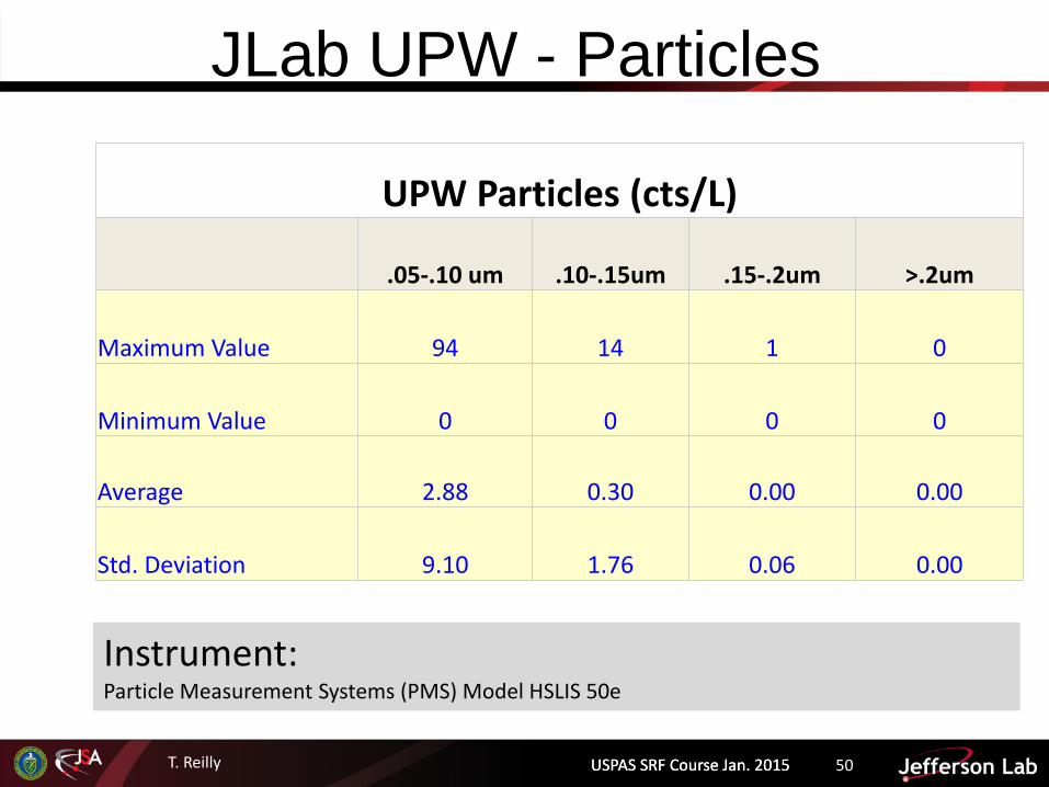
JLab UPW - Particles
UPW Particles (cts/L)
.05-.10 um .10-.15um .15-.2um >.2um
Maximum Value 94 14 1 0
Minimum Value 0 0 0 0
Average 2.88 0.30 0.00 0.00
Std. Deviation 9.10 1.76 0.06 0.00
Instrument: Particle Measurement Systems (PMS) Model HSLIS 50e
USPAS SRF Course Jan. 2015
T. Reilly
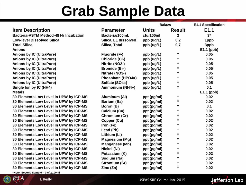
Grab Sample Data Balazs E1.1 Specification
Item Description Parameter Units Result E1.1 Bacteria-ASTM Method-48 Hr Incubation Bacteria/100mL cfu/100ml 3 3* Low-level Dissolved Silica Silica, LL dissolved ppb (ug/L) 0.2 1ppb Total Silica Silica, Total ppb (ug/L) 0.7 3ppb Anions E1.1 (ppb) Anions by IC (UltraPure) Fluoride (F-) ppb (ug/L) * 0.05 Anions by IC (UltraPure) Chloride (Cl-) ppb (ug/L) * 0.05 Anions by IC (UltraPure) Nitrite (NO2-) ppb (ug/L) * 0.05 Anions by IC (UltraPure) Bromide (Br-) ppb (ug/L) * 0.05 Anions by IC (UltraPure) Nitrate (NO3-) ppb (ug/L) * 0.05 Anions by IC (UltraPure) Phosphate (HPO4=) ppb (ug/L) * 0.05 Anions by IC (UltraPure) Sulfate (SO4=) ppb (ug/L) * 0.05 Single Ion by IC (NH4) Ammonium (NH4+) ppb (ug/L) * 0.1 Metals E1.1 (ppb) 30 Elements Low Level in UPW by ICP-MS Aluminum (Al) ppt (pg/ml) * 0.02 30 Elements Low Level in UPW by ICP-MS Barium (Ba) ppt (pg/ml) * 0.02 30 Elements Low Level in UPW by ICP-MS Boron (B) ppt (pg/ml) * 0.1 30 Elements Low Level in UPW by ICP-MS Calcium (Ca) ppt (pg/ml) * 0.02 30 Elements Low Level in UPW by ICP-MS Chromium (Cr) ppt (pg/ml) * 0.02 30 Elements Low Level in UPW by ICP-MS Copper (Cu) ppt (pg/ml) * 0.02 30 Elements Low Level in UPW by ICP-MS Iron (Fe) ppt (pg/ml) * 0.02 30 Elements Low Level in UPW by ICP-MS Lead (Pb) ppt (pg/ml) * 0.02 30 Elements Low Level in UPW by ICP-MS Lithium (Li) ppt (pg/ml) * 0.02 30 Elements Low Level in UPW by ICP-MS Magnesium (Mg) ppt (pg/ml) * 0.02 30 Elements Low Level in UPW by ICP-MS Manganese (Mn) ppt (pg/ml) * 0.02 30 Elements Low Level in UPW by ICP-MS Nickel (Ni) ppt (pg/ml) * 0.02 30 Elements Low Level in UPW by ICP-MS Potassium (K) ppt (pg/ml) * 0.02 30 Elements Low Level in UPW by ICP-MS Sodium (Na) ppt (pg/ml) * 0.02 30 Elements Low Level in UPW by ICP-MS Strontium (Sr) ppt (pg/ml) * 0.02 30 Elements Low Level in UPW by ICP-MS Zinc (Zn) ppt (pg/ml) * 0.02 *Note: Second Sample = 0 cfu/100ml
USPAS SRF Course Jan. 2015

T. Reilly USPAS SRF Course Jan. 2015 52
Summary Gained exposure to UPW in SRF: • Importance, application, system
fundamentals, materials, monitoring, basic troubleshooting, and a very brief look at hot UPW systems
• Overview of Jefferson Lab’s UPW system Hopefully, enough to make you “dangerous”
– Enhance communication and engagement – What to look out for when (if) the need arises to
select or improve a UPW system • Cavity quality issues may be related to UPW quality
issues… • Time for a tour?
USPAS SRF Course Jan. 2015