ultrafine spheroidal graphite iron castings by use of thin ...i2cxgiken.com/3. worldwide10.pdf ·...
TRANSCRIPT
* Haruki Itofuji. Tel.: +81-80-5620-4938. E-mail address: h.itofuji@keb,biglobe.ne.jp
Ultrafine spheroidal graphite iron castings by use of thin-walled
permanent molds
* Haruki Itofuji1*, Kazuya Edane2, Takehiro Sakatani3, Masayuki Itamura1
1* I2C Technology Institute, Ube 755-0025, Japan
2 Tsuchiyoshi Industry Co., Ltd., Onan 696-0403, Japan
3 Yoshiwa Kogyo Co., Ltd., Aki 736-0056 Japan
KEYWORDS
ultrafine
spheroidal graphite
thin wall
permanent mold
gravity die cast
as cast
Each keyword starts on a new line
Write up to 6 keywords
ABSTRACT
In this study, gravity die casting of spheroidal graphite iron had been
attempted controlling free nitrogen during preparing base molten iron,
magnesium treatment, inoculation and pouring. The actual CO/SiO₂ reaction
temperature of base molten irons was measured and magnesium treatment
was conducted at that temperature using a low nitrogen contained
spheroidizer agent. The size of cavity in the mold was thickness of 5.4mm
and diameter of 35mm and the mold was made of a 0.5 mass% carbon steel.
This resulted in ultrafine graphite nodules obtained without any chill in the
as-cast condition. The nodules were an average diameter of 7µm and
density count of over 3,000 n/mm². An automotive steering knuckle was also
cast using the same procedure. The knuckle had no major defects like
shrinkage, chill etc. in as-cast conditions. The possibility of no chill in this
study has become extremely higher than former study. The tensile properties
showed good improvement than that in conventional values. The study was
based on the free nitrogen theory for the chilling besides the site theory as
graphite spheroidization.
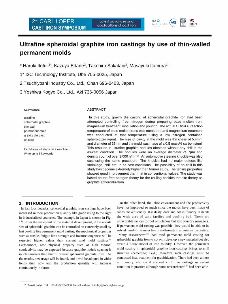
1. INTRODUCTION In last four decades, spheroidal graphite iron castings have been
increased in their production quantity like graph rising to the right
in industrialized countries. The example in Japan is shown in Fig.
11). From the viewpoint of the material development, if the nodule
size of spheroidal graphite can be controlled an extremely small by
fast cooling like permanent mold casting, the mechanical properties
such as tensile, fatigue limit strength and fracture toughness will be
expected higher values than current sand mold castings2).
Furthermore, new physical property such as high thermal
conductivity may be expected because graphite nodule spacing is
much narrower than that of present spheroidal graphite irons. As
the results, new usage will be found, and it will be adopted in wider
fields than now and the production quantity will increase
continuously in future.
On the other hand, the labor environment and the productivity
have not improved so much since the molds have been made of
sands conventionally. It is dusty, dark and hot in foundry. It needs
the wide area of sand facility and cooling bed. These are
unfavorable factors for not only labors but also foundry managers.
If permanent mold casting was possible, they would be able to be
solved mostly in manner like breakthrough in aluminum die casting.
Many researchers4-10) had tried permanent mold casting for
spheroidal graphite iron to not only develop a new material but also
create a future model of iron foundry. However, the permanent
mold casting in spheroidal graphite iron castings brings to chill
structure (cementite; Fe3C) therefore such castings must be
conducted heat treatment for graphitization. There had been almost
no foundry who could succeed chill free castings in as-cast
condition in practice although some researcheres7-9) had been able
2 2ND CARL LOPER CAST IRON SYMPOSIUM
Fig.1 Production ratio of ferrous castings for last four decades.
Fig.2 Relationship among chill depth and molten conditions in
spheroidal graphite iron
to succeed it in laboratory.
According to author’s study11), it has been clear that free nitrogen
NF in molten iron and chill depth in wedge sample have good
relationship as shown in Fig. 2. The other factors do not show the
clear relationship. It has been considered that nitrogen atom can
partially substitute carbon atom in cementite crystal structure
(Fe₃C) and enhances chill formation when the solidification rate is
fast enough. Such cementite might be the form of Fe3(C・N). If the
Table 1 Chemical composition of raw materials for gravity die
casting. denitrification could be conducted properly, there will be
no chill structure in permanent mold casting too. Finer nodule size
will be expected as the results because of fast cooling rate.
Table 1 Chemical composition of raw materials for gravity die
casting.
In this study, permanent mold casting of spheroidal graphite iron
was attempted to get ultrafine graphite nodule under stable
conditions in laboratory and to apply the technology in practice.
2. EXPERIMENTAL PROCEDURE
The raw materials for gravity die castings shown in Table 1 were
melted using a 30kg high frequency induction furnace. Melting,
magnesium treatment, inoculation, and pouring were conducted
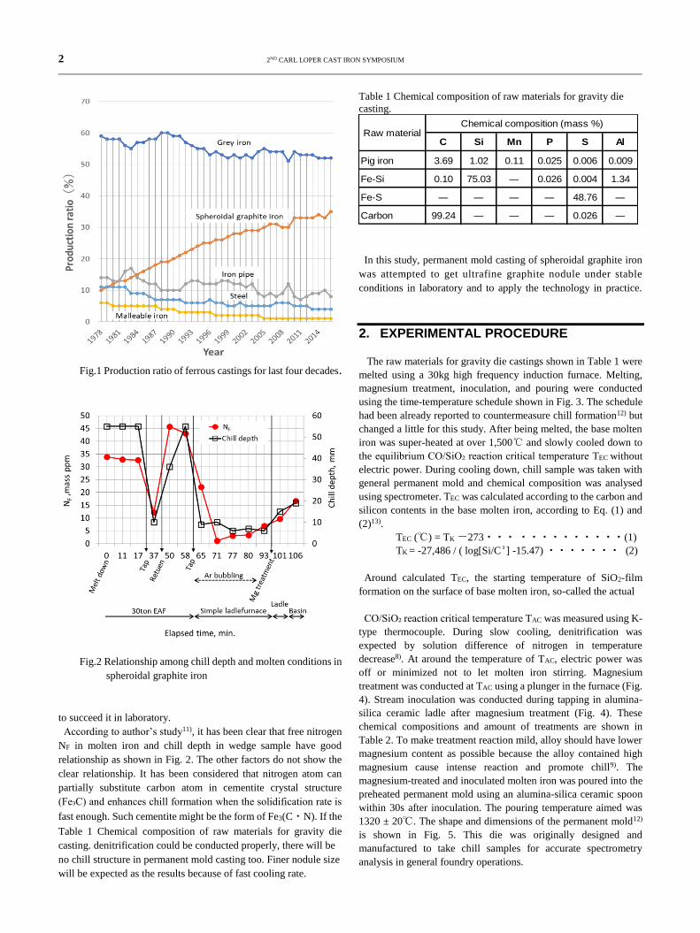
using the time-temperature schedule shown in Fig. 3. The schedule
had been already reported to countermeasure chill formation12) but
changed a little for this study. After being melted, the base molten
iron was super-heated at over 1,500℃ and slowly cooled down to
the equilibrium CO/SiO₂ reaction critical temperature TEC without
electric power. During cooling down, chill sample was taken with
general permanent mold and chemical composition was analysed
using spectrometer. TEC was calculated according to the carbon and
silicon contents in the base molten iron, according to Eq. (1) and
(2)13).
TEC (℃) = TK -273・・・ ・・・・・・・・・・(1)
TK = -27,486 / ( log[Si/C²] -15.47) ・・・・・・・ (2)
Around calculated TEC, the starting temperature of SiO2-film
formation on the surface of base molten iron, so-called the actual
CO/SiO₂ reaction critical temperature TAC was measured using K-
type thermocouple. During slow cooling, denitrification was
expected by solution difference of nitrogen in temperature
decrease8). At around the temperature of TAC, electric power was
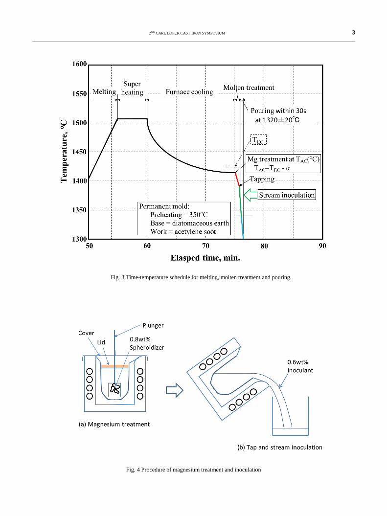
off or minimized not to let molten iron stirring. Magnesium
treatment was conducted at TAC using a plunger in the furnace (Fig.
4). Stream inoculation was conducted during tapping in alumina-
silica ceramic ladle after magnesium treatment (Fig. 4). These
chemical compositions and amount of treatments are shown in
Table 2. To make treatment reaction mild, alloy should have lower
magnesium content as possible because the alloy contained high
magnesium cause intense reaction and promote chill9). The
magnesium-treated and inoculated molten iron was poured into the
preheated permanent mold using an alumina-silica ceramic spoon
within 30s after inoculation. The pouring temperature aimed was
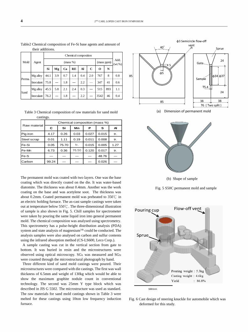
1320 ± 20℃. The shape and dimensions of the permanent mold12)
is shown in Fig. 5. This die was originally designed and
manufactured to take chill samples for accurate spectrometry
analysis in general foundry operations.
C Si Mn P S Al
Pig iron 3.69 1.02 0.11 0.025 0.006 0.009
Fe-Si 0.10 75.03 ― 0.026 0.004 1.34
Fe-S ― ― ― ― 48.76 ―
Carbon 99.24 ― ― ― 0.026 ―
Raw materialChemical composition (mass %)
2ND CARL LOPER CAST IRON SYMPOSIUM 3
Fig. 3 Time-temperature schedule for melting, molten treatment and pouring.
Fig. 4 Procedure of magnesium treatment and inoculation
4 2ND CARL LOPER CAST IRON SYMPOSIUM
Table2 Chemical composition of Fe-Si base agents and amount of
their additions.
Table 3 Chemical composition of raw materials for sand mold
castings.
The permanent mold was coated with two layers. One was the base
coating which was directly coated on the die. It was water-based
diatomite. The thickness was about 0.4mm. Another was the work
coating on the base and was acetylene soot. The thickness was
about 0.2mm. Coated permanent mold was preheated to 350℃ in
an electric holding furnace. The as-cast sample castings were taken
out at temperature below 550℃. The three-dimensional illustration
of sample is also shown in Fig. 5. Chill samples for spectrometer
were taken by pouring the same liquid iron into general permanent
mold. The chemical composition was analysed using spectrometry.
This spectrometry has a pulse-height distribution analysis (PDA)
system and state analysis of magnesium14) could be conducted. The
analysis samples were also analysed on carbon and sulfur contents
using the infrared absorption method (CS-LS600, Leco Corp.).
A sample casting was cut in the vertical section from gate to
bottom. It was buried in resin and the microstructures were
observed using optical microscopy. SGS was measured and SGN
were counted through the microstructural photograph by hand.
Three different kind of sand mold castings were poured. Their
microstructures were compared with die castings. The first was wall
thickness of 6.5mm and weight of 130kg which would be able to
show the maximum graphite nodule count in conventional
technology. The second was 25mm Y type block which was
described in JIS G 5502. The microstructure was used as standard.
The raw materials for sand mold castings shown in Table 3 were
melted for these castings using 10ton low frequency induction
furnace.
(a) Dimension of permanent mold
(b) Shape of sample
Fig. 5 S50C permanent mold and sample
Fig. 6 Cast design of steering knuckle for automobile which was
deformed for this study.
Si Mg Ca RE Al C O N
Mg alloy 44.1 3.9 0.7 1.4 0.4 2.0 767 8 0.8
Inoculant 75.8 ― 1.8 ― 2.2 — 347 41 0.6
Mg alloy 45.5 5.8 2.1 2.4 0.3 ― 515 893 1.1
Inoculant 76.2 ― 1.8 ― 2.2 ― 3542 46 0.4
Perma.
Sand
(mass ppm)(mass %)
Chemical composition
Mold AgentAdd.
(wt.%)
C Si Mn P S Al
Pig iron 4.17 0.26 0.03 0.027 0.015 tr.
Steel scrap 0.01 1.11 0.19 0.011 0.008 tr.
Fe-Si 0.05 75.70 tr. 0.015 0.005 1.27
Fe-Mn 6.73 0.36 76.50 0.120 0.017 tr.
Fe-S ― ― ― ― 48.76 ―
Carbon 99.24 ― ― ― 0.026 ―
Raw materialChemical composition (mass %)
2ND CARL LOPER CAST IRON SYMPOSIUM 5
The alloys shown in Table 2 were used for liquid treatment. The
third was wall thickness of 230mm and weight of 36,000kg which
the solidification time was controlled within 150minites using
chillers. This would be shown as a typical microstructure of heavy
section castings which the mechanical properties were guaranteed.
The casting was die-plate for injection machine15).
Although the same raw materials and alloys were added, 30ton
electric arc furnace was used in this case.
To consider the possibility of chill free gravity die casting in
spheroidal graphite iron in practice, a steering knuckle for
automobile was also poured taking the same procedure as described
above. The riserless casting design is shown in Fig. 6. A gating
system was not designed but the sprue was connected directly to the
knuckle body. The quality was surveyed about the surface, the
shrinkage, the microstructure and the tensile properties.
3. RESULTS
The chemical compositions of the molten irons are shown in Table
4. TEC of the base molten iron was calculated as 1425℃ by Eqn. (1)
and (2). After the base molten iron was super-heated to 1540℃, it
was slowly cooled down in the furnace without electric power. SiO2
film began to form at about 1415℃ when carbon and silicon were
3.66 and 2.58mass% respectively. Magnesium treatment was
conducted at 1415℃ using plunger in the furnace. The difference
between TEC and TAC was about 15℃. Soon after the magnesium
reaction finished, the molten iron was tapped into ceramic ladle.
Stream inoculation was conducted during tapping. The treated
molten iron was poured into the preheated die at 1340℃ using the
ceramic spoon. The time elapsed from inoculation to pouring was
23sec. These conditions are shown in Table 5 compering with other
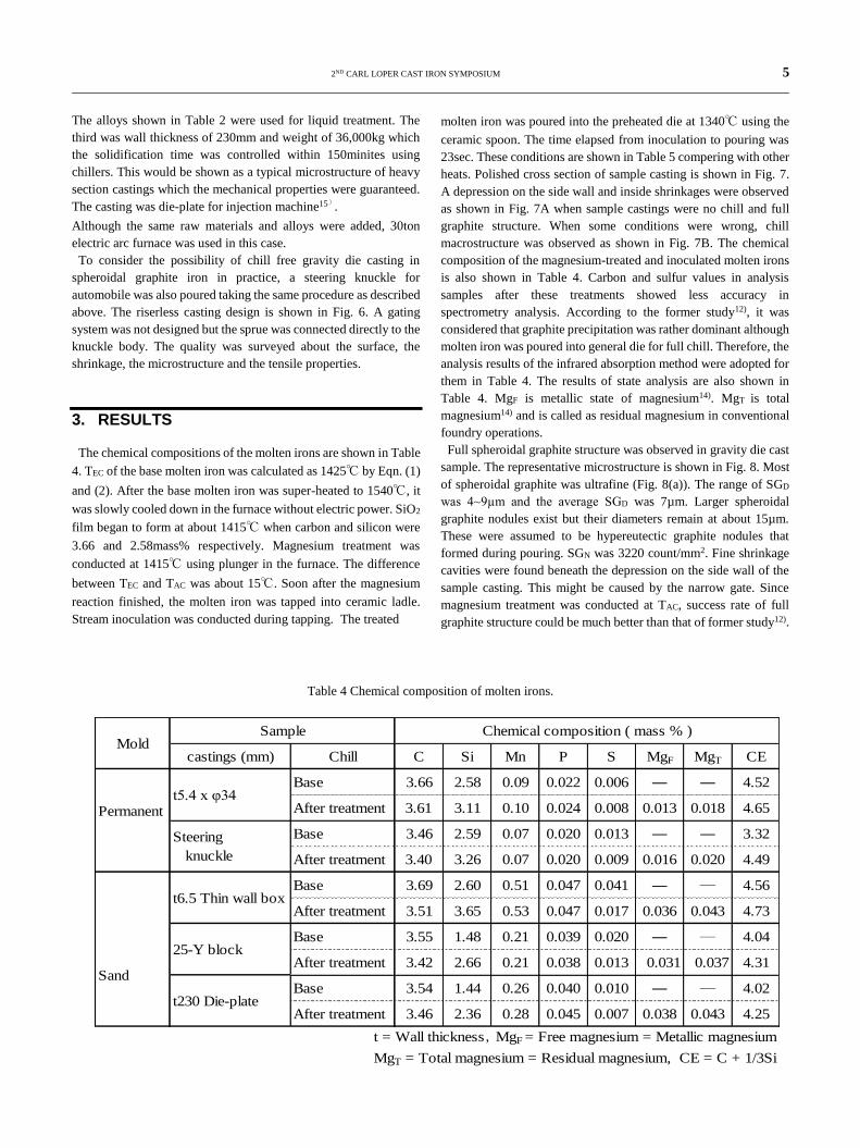
heats. Polished cross section of sample casting is shown in Fig. 7.
A depression on the side wall and inside shrinkages were observed
as shown in Fig. 7A when sample castings were no chill and full
graphite structure. When some conditions were wrong, chill
macrostructure was observed as shown in Fig. 7B. The chemical
composition of the magnesium-treated and inoculated molten irons
is also shown in Table 4. Carbon and sulfur values in analysis
samples after these treatments showed less accuracy in
spectrometry analysis. According to the former study12), it was
considered that graphite precipitation was rather dominant although
molten iron was poured into general die for full chill. Therefore, the
analysis results of the infrared absorption method were adopted for
them in Table 4. The results of state analysis are also shown in
Table 4. MgF is metallic state of magnesium14). MgT is total
magnesium14) and is called as residual magnesium in conventional
foundry operations.
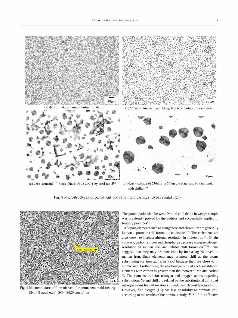
Full spheroidal graphite structure was observed in gravity die cast
sample. The representative microstructure is shown in Fig. 8. Most
of spheroidal graphite was ultrafine (Fig. 8(a)). The range of SGD
was 4~9µⅿ and the average SGD was 7µm. Larger spheroidal
graphite nodules exist but their diameters remain at about 15µm.
These were assumed to be hypereutectic graphite nodules that
formed during pouring. SGN was 3220 count/mm2. Fine shrinkage
cavities were found beneath the depression on the side wall of the
sample casting. This might be caused by the narrow gate. Since
magnesium treatment was conducted at TAC, success rate of full
graphite structure could be much better than that of former study12).
Table 4 Chemical composition of molten irons.
castings (mm) Chill C Si Mn P S MgF MgT CE
Base 3.66 2.58 0.09 0.022 0.006 ― ― 4.52
After treatment 3.61 3.11 0.10 0.024 0.008 0.013 0.018 4.65
Base 3.46 2.59 0.07 0.020 0.013 ― ― 3.32
After treatment 3.40 3.26 0.07 0.020 0.009 0.016 0.020 4.49
Base 3.69 2.60 0.51 0.047 0.041 ― ― 4.56
After treatment 3.51 3.65 0.53 0.047 0.017 0.036 0.043 4.73
Base 3.55 1.48 0.21 0.039 0.020 ― ― 4.04
After treatment 3.42 2.66 0.21 0.038 0.013 0.031 0.037 4.31
Base 3.54 1.44 0.26 0.040 0.010 ― ― 4.02
After treatment 3.46 2.36 0.28 0.045 0.007 0.038 0.043 4.25
MgT = Total magnesium = Residual magnesium, CE = C + 1/3Si
t = Wall thickness,MgF = Free magnesium = Metallic magnesium
Sand
25-Y block
t230 Die-plate
t6.5 Thin wall box
MoldChemical composition ( mass % )
Permanentt5.4 x φ34
Steering
knuckle
Sample
6 2ND CARL LOPER CAST IRON SYMPOSIUM
Table 5 Condition of melting, molten treatment and pouring in each heat.
Fig. 7 Polished cross-sectional surface of t5.4 x Φ34 as-cast sample
castings (3vol.% Nital etch).
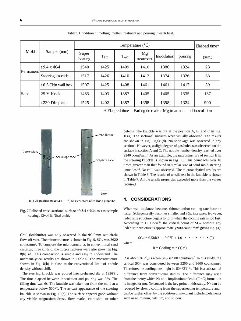
Chill (ledeburite) was only observed in the Φ3.0mm semicircle
flow-off vent. The microstructure is shown in Fig. 9. SGN was 3620
count/mm2. To compare the microstructures in conventional sand
castings, three kinds of the microstructures were also shown in Fig.
8(b)~(d). This comparison is simple and easy to understand. The
microanalytical results are shown in Table 6. The microstructure
shown in Fig. 8(b) is close to the conventional limit of nodule
density without chill.
The steering knuckle was poured into preheated die at 1326℃.
The time elapsed between inoculation and pouring was 38s. The
filling time was 6s. The knuckle was taken out from the mold at a
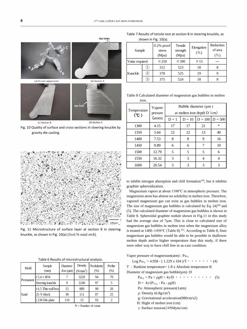
temperature below 500℃. The as-cast appearance of the steering
knuckle is shown in Fig. 10(a). The surface appears good without
any visible magnesium dross, flow marks, cold shot, or other
defects. The knuckle was cut at the position A, B, and C in Fig.
10(a). The sectional surfaces were visually observed. The results
are shown in Fig. 10(a)~(d). No shrinkage was observed in any
sections. However, a slight degree of gas holes was observed on the
surface in section A and C. The nodule number density reached over
2240 count/mm2. As an example, the microstructure of section B in
the steering knuckle is shown in Fig. 11. This count was over 10
times greater than that found in similar size of sand mold steering
knuckles16). No chill was observed. The microanalytical results are
shown in Table 6. The results of tensile test in the knuckle is shown
in Table 7. All the tensile properties exceeded more than the values
required.
4. CONSIDERATIONS
When wall thickness becomes thinner and/or cooling rate become
faster, SGD generally becomes smaller and SGN increases. However,
ledeburite structure begins to form when the cooling rate is too fast.
According to H. Horie3), the critical count of SGN without any
ledeburite structure is approximately 900 count/mm2 giving Eq. (3):
SGN = 0.58R2 + 19.07R + 1.01・・・・・・・(3)
where
R = Cooling rate (℃/s)
R is about 26.2℃/s when SGN is 900 count/mm2. In this study, the
critical SGN was considered between 3200 and 3600 count/mm2.
Therefore, the cooling rate might be 60–62℃/s. This is a substantial
difference from conventional studies. The difference may arise
from the theory which NF onto implication of chill (Fe3C) formation
is imaged or not. NF control is the key point in this study. NF can be
reduced by slowly cooling from the superheating temperature and
can be further offset by the addition of inoculant including elements
such as aluminum, calcium, and silicon.
Super
heatingTEC TAC
Mg
treatmentInoculation pouring
t 5.4 x Φ34 1540 1425 1409 1410 1386 1324 23
Steering knuckle 1517 1426 1410 1412 1374 1326 38
t 6.5 Thin wall box 1507 1425 1408 1461 1461 1417 59
25 Y-block 1483 1403 1387 1405 1405 1335 137
t 230 Die-plate 1525 1402 1387 1398 1398 1324 900
*Elasped time = Fading time after Mg treatment and inoculation
Sand
Temperature (℃) Elasped time*
(sec.)
Sample (mm)
Permanent
Mold
2ND CARL LOPER CAST IRON SYMPOSIUM 7
Fig. 9 Microstructure of flow-off vent for permanent mold casting
(3vol.% natal etch). SGN; 3620 count/mm2
The good relationship between NF and chill depth in wedge-sample
was previously proved by the authors and successfully applied in
foundry practices11).
Alloying elements such as manganese and chromium are generally
known to promote chill formation tendencies17). These elements are
also known to increase nitrogen resolution in molten iron 18). On the
contrary, carbon, silicon and phosphorus decrease increase nitrogen
resolution in molten iron and inhibit chill formation17,18). This
suggests that they may promote chill by increasing NF levels in
molten iron. Such elements may promote chill as the atoms
substituting for iron atoms in Fe3C because they are close to in
atomic size. Furthermore, the electronegativity of such substitution
elements with carbon is greater than that between iron and carbon 8). The same is true for nitrogen and oxygen atoms regarding
substitution. NF and chill are related by the substitutional ability of
nitrogen atoms for carbon atoms in Fe3C, which could promote chill.
However, free oxygen (OF) has less possibility to promote chill
according to the results of the previous study 11). Sulfur is effective
8 2ND CARL LOPER CAST IRON SYMPOSIUM
Fig. 10 Quality of surface and cross-sections in steering knuckle by
gravity die casting.
Fig. 11 Microstructure of surface layer at section B in steering
knuckle, as shown in Fig. 10(a) (3vol.% natal etch).
Table 6 Results of microstructural analysis.
Table 7 Results of tensile test at section B in steering knuckle, as
shown in Fig. 10(a).
Table 8 Calculated diameter of magnesium gas bubbles in molten
iron.
to inhibit nitrogen absorption and chill formation19), but it inhibits
graphite spheroidization.
Magnesium vapors at about 1100℃ in atmospheric pressure. The
magnesium atom has almost no solubility in molten iron. Therefore,
vapored magnesium gas can exist as gas bubbles in molten iron.
The size of magnesium gas bubbles is calculated by Eq. (4)20) and
(5). The calculated diameter of magnesium gas bubbles is shown in
Table 8. Spheroidal graphite nodule shown in Fig.11 in this study
had the average size of 7µm. This is close to calculated size of
magnesium gas bubbles in molten iron when the magnesium alloy
is treated at 1400–1450℃ (Table 8) 21). According to Table 8, finer
magnesium gas bubbles would be able to be possible in shallower
molten depth and/or higher temperature than this study, if there
were other way to have chill free in as-cast condition.
Vapor pressure of magnesium(atm) : PMg
Log PMg = 4.958 - ( 1.229 x 10⁴ )/T・・・・・・・(4)
T ;Rankine temperature= 1.8 x Absolute temperature K
Diameter of magnesium gas bubble(µm) :D
PMg = Pa + ρgH + 4γ/D ・・・・・・・・・・ (5)
D = 4γ/(PMg - Pa - ρgH)
Pa: Atmospheric pressure(1atm)
ρ: Density (6.8g/cm3)
g: Gravitational acceleration(980cm/s2)
H: Hight of molten iron (cm)
γ: Surface tension(1450dyne/cm)
t 5.4xΦ34 7 3220 94 70
Steering knuckle 9 2240 97 5
t 6.5 Thin wall box 15 889 98 20
25 Y-block 38 111 87 25
t 230 Die-plate 110 15 93 2
N = Number of count
Sand
Perlite
(%)
Permanent
Diameter
Ave.(µm)
Density
(N/mm2)
Nodularity
(%)Mold
Sample
(mm)
0.2% proof
stress
(Mpa)
Tensile
strength
(Mpa)
Elongation
(%)
Reduction
of area
(%)
≧250 ≧390 ≧15 ―
① 312 523 18 8
② 378 525 19 9
③ 375 524 18 8
Value required
Knuckle
Sample
D = 1 D = 10 D = 100 D = 500
1300 4.15 17 17 21 *
1350 5.64 12 12 13 40
1400 7.53 8 8 9 16
1450 9.89 6 6 7 10
1500 12.79 5 5 5 6
1550 16.32 3 3 4 4
1600 20.54 3 3 3 3
Bubble diameter (μm )
at molten iron depth D (cm)
Vapore
presure
(atom)
Temperature
(℃ )
2ND CARL LOPER CAST IRON SYMPOSIUM 9
P. Kainzinger, et.al22) had concluded that fatigue limit strength
improves when the density count of spheroidal graphite become
smaller in sand mold casting. Since the range of density count was
20~250count/mm2 in their study, the great improvement of fatigue
limit strength may be expected density count like this study. The
results of the tensile test make design engineers expect a much
higher fatigue limit strength value than conventional spheroidal
graphite iron castings. Furthermore, higher thermal conductivity
may be expected than that of conventional spheroidal graphite iron
because the mutual distance among nodules are much closer than
that of conventional one.
Besides nodule size and density count, full graphite structure with
no chill in knuckle casting in as-cast condition must be trustworthy.
There were some laboratories7,9,23,24) who had succeeded permanent
mold spheroidal graphite iron castings without heat treatment, but
there was almost no report for applying it in foundry practice yet.
There are some foundries5,6,25) who have taken permanent mold
casting of spheroidal graphite iron. However, they have had
graphitization heat treatment of ledeburite structure. It has been
known that graphitization heat treatment of chill irons contained
magnesium completes in a short time such as a quarter hour. This
is much shorter than that of malleable irons. But there is a
possibility to form an unfavorable microstructure such as low
nodularity, nodule line-up like discontinuous crack, etc.10). These
unfavorable microstructures depend on the distribution of
magnesium voids. Magnesium voids exist the site between
cementite and austenite in needle like ledeburite21). The sphere
shape of magnesium gas bubbles becomes irregular by ledeburite
when molten iron solidifies. Tempered graphite precipitates in
magnesium voids7). Graphite line-up may affair the mechanical
properties, especially fatigue limit strength.
It was confirmed that the NF theory11,12,26) for chill formation and
the site theory27-30) for graphite spheroidization could be used
practically to get ultrafine spheroidal graphite iron casting with no
chill in as cast condition. As the issues in next study, NF shall be
analyzed as the same procedure as former study11).
5. CONCLUSIONS
Gravity die casting of spheroidal graphite iron was attempted
controlling NF. The following results were concluded:
(1) For both the sample and steering knuckle castings, chill free
and full graphite structures could be obtained in as-cast
condition.
(2) The average SGD were 7µm in t 5.4 XΦ34mm casting and
9µm in Knuckle casting. They had been never reported by
other researchers before.
(3) On the magnesium treatment temperature as one of
conditions to get full graphite structure, TAC was more stable
condition than TEC.
(4) New adoption of ultrafine spheroidal graphite iron castings
may be expected for industrial use.
REFERENCES
1) Sokeizai center; Material yearbook (2017)
2) P.Kainzinger und F.Grun; Giesserei Rundschau
61(2014)Nr.11+12, s347~351
3) H. Horie; Imono 67 (2) (1995) 124-132.
4) H. Sakurai, M. Kawasaki, K. Ozaki; Technical Paper 945189,
FISTA Congress (1994).
5) Y.S. Lerner; Foundry Management & Technology, Oct.
(2003) 18-22.
6) A. Urrestarazu, J. Sertucha, R. Suarez, I. Alvarez-Ilzarbe; Rev.
Metala. 49 (2013)325-339.
7) Y. Lee, et al.; Imono 55 (1983)156-163.
8) N. Inoyama, S. Yamamoto, Y. Kawano; Cast Irons clarified
Through Bonds and Reactions (1992).
9) T. Kitsudou, K. Ashida, K. Fujita; Imono 62 (1990) 359-364.
10) Permanent Mold Casting of Irons; Japan Foundry Society
(1976)
11) H. Itofuji, M. Tamura, Moritake, M. Itamura, K. Anzai;
Imono,163th conference (2013) 99.
12) H. Itofuji, K. Kazuya, T. Kotani, M. Itamura, K. Anzai;
Proceedinds of CastTec2016 (2016)
13) B. Marineki; Modern Casting, 42 (6) (1962) p99.
14) H. Itofuji, K. Kawamura, N. Hashimoto, H, Yamada; AFS
Trans.,98(1990)585-595.
15) H. Itofuji;Int. J. Cast Metals Res. 12 (1999)179-187
16) K. Edane, Y. Ameku, Y. Kurokawa, H. Itofuji, M. Itamura, K.
Anzai; Imono,168th conference (2016) 151
17) K. Taniguchi; Tetsu-to-Hagane18 (1932)952-980.
18) R.D. Pehlke; Trans. Met. Soc. AIME, 218 (1960)1088.
19) T. Choh, M. Inoue; Tetsu-to-Hagane 54(1968)19
20) P.K. Trojan, R.A. Flinn; Trans. ASM,54(1961)549-566
21) H. Itofuji;Int. J. Cast Metals Res., 17 (2004)220-228
22) P. Kainzinger und F. Grun; Giesserei Rundschau 61(2014)
Nr.11+12, s347~351
23) M. S. C. Rao, M. N. Srinivasan; AFS Trans.,96(1988) 79-89
24) K. G. Davis, J. G. Magny, D. A. Brown and D. Hui; Advanced
Casting Technology, Proc. Conf. Kalamazoo, MI Nov 12- 14
(1986)221-230.
25) H. Sakurai, M. Kawaguti and K. Osaki; The Integration of
Design and Manufacture (1994)55-61
26) H. Itofuji, K. Edane, Y. Kurokawa, M. Itamura, K. Anzai;
Imono,168th conference (2016) 148.
27) H. Itofuji;Thesis of Kyoto University (1993).
28) H. Itofuji; AFS Trans.,104(1996)79-87
29) H. Itofuji; Imono, 84(2012)194-202
30) H. Itofuji; Imono, 90(2018)587-593
ACKNOWLEDGEMENT
Authors wish to express our sincere gratitude to Professor Koichi
Anzai for his supervision, helpful suggestion and continual
encouragement throughout this study.