ultra power saving for street lighting system · pdf fileultra power saving for street...
TRANSCRIPT

ULTRA POWER SAVING FOR STREET LIGHTING SYSTEM
A.N.Bharath (M.Tech), E.S., contact:+918008970079,E-mail id: [email protected],SIETK, Puttur.
M.MariMuthu M.E., Assistant professor ,contact:+919703601171,E-mailid:[email protected],SIETK, Puttur.
ABSTRACT: In this paper an ultra power saving
for street lighting has been implemented. It helps to
reduce the unnecessary power consumption due to
over illumination in natural light. By using RTC
(Real-Time-Clock) and it generates the timer
automatically. With the help of PIR sensor the
presence of a person or any obstacle detected by
using the presence detector. Street lights will be
switched ON only when a person on any obstacle
comes in the detection range else it will be
automatically dimmer mode. The designed system
avoids the human intervention in power
management. It displays the particular billing
information on LCD and data can be sent to the
prescribed number by using GSM module.
I. INTRODUCTION
Streetlights are an integral part of any
developing locality. They are present on all major
roadways and in the suburbs too. Every day,
streetlights are powered from sunset to sunrise at
full strength, even when there is no one around. On
a global scale, millions of dollars are spent each
day on these street lights to provide the required
electrical energy. This system is commonly used in
all streets of street light system. But in this method,
there is a loss of heavy electricity in the whole
night. If the street light is not stopped after the
night, the loss will continue throughout the day.
And also the street light illumination is not
necessary when there are no human movements in
the street. So to come out of these disadvantages
this project this allows the significant cost savings
and a greater respect for the environment.
So, the environmental issues have gained
widespread international attention, resulting in the
development of energy-efficient technologies
aimed at reducing energy consumption. One aspect
of the situation is an increasing demand for the
reduction of the amount of electricity used for
illumination. In particular, energy conservation for
large scale illumination tasks such as street lighting
is gaining considerable importance. The street light
system is one of the largest energy expenses for a
city, accounting for upwards of 35-45% of a
municipality’s utility budget .The power saving
lighting control system can cut municipal street
lighting costs as much as 70%. This lighting system
is a system that adjusts light intensity based on
usage and occupancy of the traffic as it illuminates
a certain number of street lights ahead and fewer
behind, depending on movement of vehicles.
The main objective of this project is to design
an ultra power saving for street lighting system.
The most use of new technologies for the sources
of light is presented. In this area, the PIR sensor is
used to find the human movements and vehicle
movements or any oscillation between any objects
in streets. When the presence is detected, all
surrounding street lights glow at their brightest
mode, else they stay in the dim mode. Incandescent
bulb is the source electric light works by
incandescence (general term for heat driven light
emission). It has the lowest efficiency or the
highest power consumption among the lights,
which the power are mostly wasted in the bulb
heating So, this control can be implemented
through a GSM network of sensors to collect the
International Journal of Scientific & Engineering Research, Volume 7, Issue 5, May-2016 ISSN 2229-5518
1925
IJSER © 2016 http://www.ijser.org
IJSER

relevant information related to the management and
maintenance of the system, send the information
via SMS by using the GSM network.It is used to
monitor the street light status and to control the
street lights in emergency condition. To control this
PIR sensor here, we are using the ARM7
(LPC2148) microcontroller to communicate with
all the peripherals present in the project.
II. PROPOSED SYSTEM
In the proposed system, we implemented
five new things are there. They are:
1) RTC (Real-Time-Clock).
2) PIR Sensor 1&2.
3) Relay (ULN2803).
4) Incandescent Bulbs.
5) ARM7 (LPC2148).
In the figure1 shows that block diagram
of the proposed system. Here we are using
LPC2148 which is an advanced RISC machine. It
is a 32 bit controller which follows von Neumann
architecture. While we switch on the power supply
the experimental operation will takes place in
evening 7pm to 7am. How means based on RTC
timing conditions. It is capable of changing its
luminance level during day and night time. By
using PIR sensor, the presence of a person or any
obstacle is detected by using presence detector
sensors. Street lights will be switched ON only
when a person or an obstacle comes in the
detection range else the light will be dimming
mode. Incandescent bulbs can be implemented here
because of more efficiency and it can be easily
identified the light dimming mode and brightness
mode. With the help of Relay Driver (ULN2803),
we used 4 relays. By using these relays we can
control the power supply for light brightness and
dimming mode. For light brightness mode the
voltage can takes in 220V and for dimming mode
the voltage can takes place in 110V.So, for these
purpose power supply can control by relay. Finally,
it displays the corresponding billing information on
LCD displaying unit and data can be send in the
form of SMS way through the GSM Module. The
ARM7 (LPC 2148) based hardware system consists
of a processor core board and the peripheral board.
The entire programming for microcontroller
operation is based on Embedded C Language in
Keil software. If this ultra power saving for street
lights is designed and installed in the cities, then,
lot of power can be saved and this will also
minimize the cost of maintenance over traditional
wired systems.
A. BLOCK DIAGRAM
Fig1:Block diagram of the proposed
system.
ARM
L
P
C
2
1
4
8
POWER
SUPPLY
LCD RELAY
DRIVE
ULN-
2
8
0
3
GSM
RELAY 1
1111
RELAY 2
1111
RELAY 3
1111
RELAY 4
1111
PIR 1
PIR 2
RTC(Real-
Time-Clock)
International Journal of Scientific & Engineering Research, Volume 7, Issue 5, May-2016 ISSN 2229-5518
1926
IJSER © 2016 http://www.ijser.org
IJSER

B. FLOW CHART
NO
Yes
Fig 2: Flow chart of the proposed system.
C. APPLICATIONS
1) Cities or any remote areas also.
2) Hospitals.
3) Educational Institutions.
4) Industries.
D. ADVANTAGES
1) RTC (Real Time Clock) can work based
on given timing conditions.
2) The range of PIR sensor is very high.
3) It can detect up to 6mts.
4) Billing rates will be reduced.
5) Manual work can be reduced.
III. RESULTS
When the power supply is connected to the
supply unit. Port connections are given to the Port
P0.11 is connected to PIR1 and P0.12 is connected
to PIR2 sensor. The port P1.16 is for RS and P1.17
is for RW and P1.18 is for EN pins. These 3 are
control lines. P1.24 to P1.31 is connected to LCD
for data lines connections (D0-D7). GSM is
connected to UART 0. Relay connections are P1.21
for relay1 and P1.22 for relay 2 and P1.23 for relay
3 and P1.24 is for relay 4.
The experimental results are as shown as
below. Here we have taken two conditions namely
Condition 1: Both the street lights are in
dimming mode.
Fig3: Both the street lights are in dim mode.
Start
Initialise all the
devices
If PIR
Sensor
detects?
Lights are in bright mode.
Lights are in dim
mode.
Displays how much power
consumed & power save in
LCD unit.
Finally message can be sent to
the prescribed number through
the GSM.
In RTC, we set the time
between 7am-7pm. At
7pm lights will be
automatically ON.
Stop
At 7am comes lights will be
automatically off.
International Journal of Scientific & Engineering Research, Volume 7, Issue 5, May-2016 ISSN 2229-5518
1927
IJSER © 2016 http://www.ijser.org
IJSER
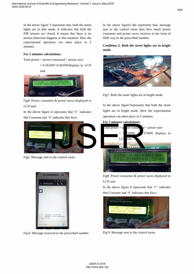
In the above figure 3 represents that, both the street
lights are in dim mode. It indicates that both the
PIR sensors are closed. It means that there is no
motion detection happens at this moment. Here the
experimental operation can takes place in 2
minutes.
For 2 minutes calculations:
Total power = power consumed + power save
= 0.5610W+0.5610Wdisplays in LCD
unit.
Fig4: Power consumes & power saves displayed in
LCD unit.
In the above figure 4 represents that ‘C’ indicates
that Consume and ‘S’ indicates that Save.
Fig5: Message sent to the control room.
Fig 6: Message received to the prescribed number.
In the above figure5 &6 represents that, message
sent to the control room then how much power
consumes and power saves receives in the form of
SMS way to the prescribed number.
Condition 2: Both the street lights are in bright
mode.
Fig7: Both the street lights are in bright mode.
In the above figure7represents that both the street
lights are in bright mode. Here the experimental
operation can takes place in 5 minutes.
For 5 minutes calculations:
Total power = power consumed + power save
= 2.2100W + 0.3740W displays in
LCD unit.
Fig8: Power consumes & power saves displayed in
LCD unit.
In the above figure 8 represents that ‘C’ indicates
that Consume and ‘S’ indicates that Save.
Fig 9: Message sent to the control room.
International Journal of Scientific & Engineering Research, Volume 7, Issue 5, May-2016 ISSN 2229-5518
1928
IJSER © 2016 http://www.ijser.org
IJSER

Fig10: Message received to the prescribed number.
In the above figure10 represents that, how much
power consumes and power save received to the
prescribed number.
Tabular Column:
S.N
o.
Conditi
ons
Ti
me(
Sec
)
Power
Consume
in (W)
Power
save
in (W)
Total
powe
r(W)
1 Both
the
street
lights
are in
dim
mode.
For
2
min
ute
s
0.5610
(W)
0.561
0 (W)
1.122
0 (W)
2 Both
the
street
lights
are in
bright
mode.
For
5
min
ute
s
2.2100
(W)
0.374
0(W)
2.584
0 (W)
Table 1: Power calculated in minutes format.
S.n
o
Conditio
ns
Time(
s)
Power
consu
me in
(W)
Pow
er
Save
in
(W)
Total
power
(W)
1 Both the
street
lights
are in
dim
mode.
1
hour
16.830
W
16.83
0 W
33.66
W
2 Both the
street
lights
are in
bright
mode.
1
hour
26.524
W 4.704
W 31.228
W
Table 2: Power calculations in one hour format.
S.
No
.
Condit
ions
Time
(S)
Power
consu
me in
(W)
Power
save
in (W)
Total
power
(W)
1. Both
the
street
lights
are in
dim
mode.
For
12
hour
s
201.96
(W) 201.96
(W)
403.92(
W)
2. Both
the
street
lights
are in
bright
mode.
For
12
hour
s
318.28
8(W)
56.448
(W)
374.73
6(W)
Table 3: Power calculations in 12 hour format.
International Journal of Scientific & Engineering Research, Volume 7, Issue 5, May-2016 ISSN 2229-5518
1929
IJSER © 2016 http://www.ijser.org
IJSER
IV. CONCLUSION
The proposed system can detect
day/night time and vehicles and vary the
intensity of the street lights using RTC
(Real–Time-Clock) technique in
incandescent lamps as per the traffic flow.
With the help of Relay the street lights can
control in the position of On/Off/dimming
mode. Thus, if an ultra power saving for
street lighting system can designed and
installed in the cities, then, lots of power
can be saved. In which integrates new
technologies available on the market to
offer higher efficiency and considerable
savings. Another advantage obtained by
the control system in power saving
management of the lamp posts by sending
data to a central station by using GSM
communication. The proposed system is
particularly suitable for street lighting in
urban and rural areas where the traffic is
low at a given range of time. The goal is,
therefore, reduction of power consumption
and harmful atmosphere emissions. The
system is versatile and can be extended
according to user needs.
V. FUTURE SCOPE
After having implemented this
ultra power saving for street lighting
system, what remains is the scope for
improvements. Firstly, we could directly
go for Wireless Power Transmission
which would further reduce the
maintenance costs and power thefts of the
system, as cable breaking is one of the
problems faced today. In addition to this,
controlling the Traffic Signal lights would
be another feature that we could look into
after successful implementation of our
system. Depending on the amount of
traffic in a particular direction, necessary
controlling actions could be taken.
Moreover, attempts can be made to ensure
that the complete system is self-sufficient
on nonconventional energy resources like
solar power, windmills, Piezo-electric
crystals, etc. We hope that these
advancements can make this system
completely robust and totally reliable in
all respects.
VI. ACKNOWLEDGEMENT
We would like to thank our mentor and
Asst.Prof. M. Mari Muthu(M.E.) for
guidance and help throughout our project.
We are also thank full to our institute
Siddharth institute of engineering &
technology (SIETK), Puttur, for providing
all the facilities needed for our project.
VII. REFERENCES
[1] Wu Yue; Shi Changhong; Zhang Xianghong;
Yang Wei; , "Design of new intelligent street light
control system," Control and Automation (ICCA),
2010 8th IEEE International Conference on , vol.,
no., pp.1423- 1427, 9-11 June 2010.
[2] Caponetto, R.; Dongola, G.; Fortuna, L.;
Riscica, N.; Zufacchi, D.; , "Power consumption
reduction in a remote controlled street lighting
system," Power Electronics, Electrical Drives,
Automation and Motion, 2008. SPEEDAM 2008.
International Symposium on , vol., no., pp.428-
433, 11-13 June 2008.
[3] P. Zerfos, X. Meng, S. Wong, V. Samanta, and
S. Lu, “A study of the short message service of a
nationwide cellular network,” in ACM SIGCOMM
Internet Measurement Conf., Oct. 2006.
[4] Mitsunori Miki, Tomoyuki Hiroyasu, Kazuhiro
Imazato, “Proposal for an Intelligent Lighting
System, and Verification of Control Method
Effectiveness”, June, 2007.
[5] Brian Chemel, “Intelligent Lighting Systems -
An Application-Centric Look at the Future”, DoE
SSL R&D Workshop, February, 2012.
[6] Liu Chee Wei, “Smart Lighting Systems:
Modular Intelligent Control System”, May 2011.
[7] P. Zerfos, X. Meng, S. Wong, V. Samanta, and
S. Lu, “A study of the short message service of a
nationwide cellular network,” in ACM SIGCOMM
Internet Measurement Conf., Oct. 2006.
International Journal of Scientific & Engineering Research, Volume 7, Issue 5, May-2016 ISSN 2229-5518
1930
IJSER © 2016 http://www.ijser.org
IJSER