ultra-low power design of multimodal bio-signal wearable systems mamaghania… · ·...
TRANSCRIPT

Ultra-Low Power Design of Multimodal Bio-Signal Wearable Systems
Embedded Systems Laboratory (ESL), Laboratory of Signal Processing (LTS2)
EPFL, Switzerland
ICT Summer School Fiuggi, Italy July 9th, 2015
Hossein Mamaghanian

© EPFL 2015
▪ This calls for a two-fold paradigm shift in health delivery:
Symptom-based ➔ Preventive healthcare Hospital-centered sickcare ➔ Person-centered healthcare
Pressing Changes in Healthcare Landscape and Economics Call for Personalized Healthcare
▪ The burden of disease is shifting from diseases caused by infectious organisms to disorders with behavioral causes
▪ 50% of all deaths worldwide in 2006 and economic fallout in billions… expected to be 75% of gross domestic product by 2030
2
Environment
GeneticsAccess to care
Health behaviors/personal lifestyle
Determinants of health issues (source: Institute for the future, Center for
disease control and prevention, 2006)

WBSN is a major technology for wearable personal health systems
• Outfitting people with sensor collecting vital signals.
• Many sensor: ECG, EMG, EEG, Accelerometer ,…
• <> Huge bandwidth required
• <> High power consumption
• Increasing demand for long time monitoring
• Autonomy and lifetime
• Main Challenge: • power efficient ✔
• bandwidth ✔
• small in form factor, light in weight3
Wireless body area network (WBSN or WBAN)
Multi-parametric bio-signals analysis:
How to design a WBSN?

© EPFL 2015
State-of-the-Art WBSN Designs:Streaming of Raw Data
4
Long-term ECG monitor (Holter or event recorder)
Voltage
Time

© EPFL 2015
State-of-the-Art WBSN Designs:Streaming of Raw Data
4
MyHeart (Luprano,2006)
Health@Home (Sánchez, 2010) MobiHealth (Halteren,2004) TEMPO (Barth,2009)
Kai,2011
Thiemjarus (2005-11)
Streaming of only raw biosignal dataToumaz digital plaster (2011-13)Long-term ECG monitor
(Holter or event recorder)
Shimmer (2011)
module of TI MSP430 microcontroller, and works in single-channel single conversion mode with 2.5V reference voltage, using a sampling frequency of 512Hz. The accurate sampling period is triggered by a timer pulse. After packing the 12-bit data, MSP430 controls the Bluetooth module to send data.
In the wireless transmission section, the commonly used BC4 Series Bluetooth chip of CSR company is selected to communicate with the microcontroller serial port with 9600 baud rate. Furthermore, it is confidential and stable with the transmission distance up to 5 meters.
E. Display Software on Mobile Phone The display software at Mobile terminal which can be ran
on the smart phone with Windows Mobile operating system is developed in Microsoft Visual Studio 2008 integrated development environment using C # .
It mainly consists of the Bluetooth receiving program, display program and interactive interface program. Bluetooth receiving program detects an available port number firstly, then connects the detected port to the Bluetooth serial port, finally receives the packed data extracted from ECG monitoring; Display program unpacks the received data according to the control parameters and displays the data on the phone screen. Interactive interface program is capable of controlling and scaling the waveform in the horizontal and vertical direction and a suspended function. The software interface of Mobile terminal display will be introduced in Part III
III. IMPLEMENTATION & IN-VITRO TEST Fig. 9 shows the physical figure of the system, the volume
is 5.5 cm × 3.4 cm × 1.6 cm, weight is only 20.76 g (without batteries), and power consumption is 115 mW. It is supplied by lithium batteries or USB power, and can continuously work for more than 7 hours with supplying by the ordinary lithium batteries (300 mAh).
All the tests are based on the standard three-lead connection: the red lead is connected to the right chest, the white lead is connected to the left chest, and the black lead is connected to the right abdomen as a reference. Fig. 10 display the software interface on the phone where ECG signal and the characteristics of the ECG PQRST wave band can be clearly seen. The display interface is smart and capable of adjusting the display size, searching for Bluetooth serial port, mobilizing waveforms and the other functions. Bluetooth communication distance can be up to 5 meters above.
IV. CONCLUSIONS Aiming to resolving the constraints of the conventional
ECG, such as the large volume, not real-time display, using limited by time and place, this paper proposes a portable mobile ECG monitoring system based on Bluetooth. The system integrates the amplifying circuit with a new dry skin electrodes by MEMS technology into a ASIC, which not only greatly reduce the size and weight, but also extract the ECG signal more accurately as compared to the conventional electrodes. Moreover the system is suitable for long-term measurement; Base on the wireless Bluetooth technology, the
Figure 9. Physical figure of the system
Figure 10. Three-lead ECG signal on display software
system can real-time display the ECG signal on the Bluetooth terminal (such as Bluetooth mobile phones), making the display interface separated from the acquisition system conveniently.
The ECG signal detected by the proposed system can be clearly distinguished the characteristics of the PQRST wave band, with features of convenient and real-time, it is expected to provide a new means of diagnosis and prevention of cardiovascular disease.
REFERENCES [1] Belgacem N , Bereksi-Reguig F, “Bluetooth Portable Device for ECG
and Patient Motion Monitoring”, Nature & Technology, pp 19 - 23January 2011.
[2] J. Jossinet and E. T. McAdams, “The skin-electrode interface impedance”, Innov. Tech.Med, vol. 12 , pp.21 -31, 1991.
[3] Wang Y, Guo K, Pei W H, GUI Q, LI X Q CHEN H D, “Fabrication of Dry Electrode for Recording Bio-potentials,” Chinese Phys. Lett , 2011, vol.28,pp. 010701.
[4] Harrison R, Charles C, “A low-power low-noise CMOS amplifier for ECG recording applications,” IEEE Journal of Solid-State Circuits, vol.38, pp. 958-965, 2003.
[5] Jochum T, Denison T, Wolf P, “Integrated circuit amplifiers for multi-electrode intracortical recording. Journal of ECG Engineering,”, vol.6, pp. 1-26, 2009.
[6] Zhang X, Pei W H , Huang B J, “Low Power CMOS Preamplifier for ECG Recording Applications,” Chinese Journal of Semiconductors, vol.31, pp. 045002-1 - 045002-6,2010.
[7] Gui Y, Zhang X, Pei W H, Chen H D, “A smart 16-channel front-end system for extracelluar ECG recording,” 2nd Asia Pacific Conference on Postgraduate Research in Microelectronics and Electronics, pp.402-411,2010.
[8] Jochum T, Denison T, Wolf P, “Integrated circuit amplifiers for multi-electrode intracortical recording,” Journal of ECG Engineering, vol.6, pp. 1-26,2009.
Fig. 3. (a) Wireless 3-lead ECG sensor, (b) ECG Strap, (c) SpO2 sensor, and the PDA base station.
4. References
[1] BARROSO A., BENSON J., MURPHY T., ROEDIG U., SREENAN C., BARTON J., BELLIS S., O'FLYNN B. and DELANEY K., The DSYS25 Sensor Platform, Proceedings of the ACM SenSys ’04, 2004.
[2] LISZKA K.J., MACKIN M.A., LICHTER M.J., YORK D.W., PILLAI D. and ROSENBAUM D. S., Keeping a Beat on the Heart, IEEE Pervasive Computing, Oct-Dec 2004; 3(4):42-49.
[3] PANIDIS IP and MORGANROTH J., Sudden death in hospitalized patients: cardiac rhythm disturbances detectedby ambulatory electrocardiographic monitoring, J Am Coll Cardiol. 1983 Nov; 2(5):798-805.
[4] PENTLAND A., Healthwear: Medical Technology Becomes Wearable, IEEE Computer, May 2004; 37(5): 42-49.
[5] PETERSEN S., PETO V. and RAYNER M., Coronary heart disease statistics 2004, British Heart Foundation,June 2004.
[6] ROSS P.E., Managing Care Through The Air, IEEE Spectrum, Dec 2004; 14-19.
[7] STANDING P., DENT M., CRAIG A. and GLENVILLE B., Changes in referral patterns to cardiac out-patient clinics with ambulatory ECG monitoring in general practice, The British Journal of Cardiology, June 2001;8 (6): 396-398.
[8] TAPIA E.M., MARMASSE N., INTILLE S.S. and LARSON K. MITes: Wireless Portable Sensors for Studying Behavior, Proceedings of the UbiComp 2004, Sept 2004.
[9] http://particle.teco.edu/
[10] http://www.btnode.ethz.ch/
[11] http://www.intel.com/research/exploratory/motes.htm
[12] http://www.tinyos.net
80

© EPFL 2015
State-of-the-Art WBSN Designs:Streaming of Raw Data
4
MyHeart (Luprano,2006)
Health@Home (Sánchez, 2010) MobiHealth (Halteren,2004) TEMPO (Barth,2009)
Kai,2011
Thiemjarus (2005-11)
Streaming of only raw biosignal data
Since the WBSN nodes do not do any processing, how much can they last? Only 2-3 days…
Toumaz digital plaster (2011-13)Long-term ECG monitor (Holter or event recorder)
Shimmer (2011)
module of TI MSP430 microcontroller, and works in single-channel single conversion mode with 2.5V reference voltage, using a sampling frequency of 512Hz. The accurate sampling period is triggered by a timer pulse. After packing the 12-bit data, MSP430 controls the Bluetooth module to send data.
In the wireless transmission section, the commonly used BC4 Series Bluetooth chip of CSR company is selected to communicate with the microcontroller serial port with 9600 baud rate. Furthermore, it is confidential and stable with the transmission distance up to 5 meters.
E. Display Software on Mobile Phone The display software at Mobile terminal which can be ran
on the smart phone with Windows Mobile operating system is developed in Microsoft Visual Studio 2008 integrated development environment using C # .
It mainly consists of the Bluetooth receiving program, display program and interactive interface program. Bluetooth receiving program detects an available port number firstly, then connects the detected port to the Bluetooth serial port, finally receives the packed data extracted from ECG monitoring; Display program unpacks the received data according to the control parameters and displays the data on the phone screen. Interactive interface program is capable of controlling and scaling the waveform in the horizontal and vertical direction and a suspended function. The software interface of Mobile terminal display will be introduced in Part III
III. IMPLEMENTATION & IN-VITRO TEST Fig. 9 shows the physical figure of the system, the volume
is 5.5 cm × 3.4 cm × 1.6 cm, weight is only 20.76 g (without batteries), and power consumption is 115 mW. It is supplied by lithium batteries or USB power, and can continuously work for more than 7 hours with supplying by the ordinary lithium batteries (300 mAh).
All the tests are based on the standard three-lead connection: the red lead is connected to the right chest, the white lead is connected to the left chest, and the black lead is connected to the right abdomen as a reference. Fig. 10 display the software interface on the phone where ECG signal and the characteristics of the ECG PQRST wave band can be clearly seen. The display interface is smart and capable of adjusting the display size, searching for Bluetooth serial port, mobilizing waveforms and the other functions. Bluetooth communication distance can be up to 5 meters above.
IV. CONCLUSIONS Aiming to resolving the constraints of the conventional
ECG, such as the large volume, not real-time display, using limited by time and place, this paper proposes a portable mobile ECG monitoring system based on Bluetooth. The system integrates the amplifying circuit with a new dry skin electrodes by MEMS technology into a ASIC, which not only greatly reduce the size and weight, but also extract the ECG signal more accurately as compared to the conventional electrodes. Moreover the system is suitable for long-term measurement; Base on the wireless Bluetooth technology, the
Figure 9. Physical figure of the system
Figure 10. Three-lead ECG signal on display software
system can real-time display the ECG signal on the Bluetooth terminal (such as Bluetooth mobile phones), making the display interface separated from the acquisition system conveniently.
The ECG signal detected by the proposed system can be clearly distinguished the characteristics of the PQRST wave band, with features of convenient and real-time, it is expected to provide a new means of diagnosis and prevention of cardiovascular disease.
REFERENCES [1] Belgacem N , Bereksi-Reguig F, “Bluetooth Portable Device for ECG
and Patient Motion Monitoring”, Nature & Technology, pp 19 - 23January 2011.
[2] J. Jossinet and E. T. McAdams, “The skin-electrode interface impedance”, Innov. Tech.Med, vol. 12 , pp.21 -31, 1991.
[3] Wang Y, Guo K, Pei W H, GUI Q, LI X Q CHEN H D, “Fabrication of Dry Electrode for Recording Bio-potentials,” Chinese Phys. Lett , 2011, vol.28,pp. 010701.
[4] Harrison R, Charles C, “A low-power low-noise CMOS amplifier for ECG recording applications,” IEEE Journal of Solid-State Circuits, vol.38, pp. 958-965, 2003.
[5] Jochum T, Denison T, Wolf P, “Integrated circuit amplifiers for multi-electrode intracortical recording. Journal of ECG Engineering,”, vol.6, pp. 1-26, 2009.
[6] Zhang X, Pei W H , Huang B J, “Low Power CMOS Preamplifier for ECG Recording Applications,” Chinese Journal of Semiconductors, vol.31, pp. 045002-1 - 045002-6,2010.
[7] Gui Y, Zhang X, Pei W H, Chen H D, “A smart 16-channel front-end system for extracelluar ECG recording,” 2nd Asia Pacific Conference on Postgraduate Research in Microelectronics and Electronics, pp.402-411,2010.
[8] Jochum T, Denison T, Wolf P, “Integrated circuit amplifiers for multi-electrode intracortical recording,” Journal of ECG Engineering, vol.6, pp. 1-26,2009.
Fig. 3. (a) Wireless 3-lead ECG sensor, (b) ECG Strap, (c) SpO2 sensor, and the PDA base station.
4. References
[1] BARROSO A., BENSON J., MURPHY T., ROEDIG U., SREENAN C., BARTON J., BELLIS S., O'FLYNN B. and DELANEY K., The DSYS25 Sensor Platform, Proceedings of the ACM SenSys ’04, 2004.
[2] LISZKA K.J., MACKIN M.A., LICHTER M.J., YORK D.W., PILLAI D. and ROSENBAUM D. S., Keeping a Beat on the Heart, IEEE Pervasive Computing, Oct-Dec 2004; 3(4):42-49.
[3] PANIDIS IP and MORGANROTH J., Sudden death in hospitalized patients: cardiac rhythm disturbances detectedby ambulatory electrocardiographic monitoring, J Am Coll Cardiol. 1983 Nov; 2(5):798-805.
[4] PENTLAND A., Healthwear: Medical Technology Becomes Wearable, IEEE Computer, May 2004; 37(5): 42-49.
[5] PETERSEN S., PETO V. and RAYNER M., Coronary heart disease statistics 2004, British Heart Foundation,June 2004.
[6] ROSS P.E., Managing Care Through The Air, IEEE Spectrum, Dec 2004; 14-19.
[7] STANDING P., DENT M., CRAIG A. and GLENVILLE B., Changes in referral patterns to cardiac out-patient clinics with ambulatory ECG monitoring in general practice, The British Journal of Cardiology, June 2001;8 (6): 396-398.
[8] TAPIA E.M., MARMASSE N., INTILLE S.S. and LARSON K. MITes: Wireless Portable Sensors for Studying Behavior, Proceedings of the UbiComp 2004, Sept 2004.
[9] http://particle.teco.edu/
[10] http://www.btnode.ethz.ch/
[11] http://www.intel.com/research/exploratory/motes.htm
[12] http://www.tinyos.net
80

© EPFL 2015
The Shimmer™ WBSN platform
▪ TI MSP430 microcontroller ▪ 16-bit, 8MHz, 10KB RAM, 48KB Flash ▪ ADC converters, DMA, HW multiplier
▪ CC2420 radio ▪ 250 Kbps, ZigBee compliant
▪ Sensors ▪ 3-channel ECG ▪ Accelerometers and gyroscopes
5

© EPFL 2015
The Shimmer™ WBSN platform
▪ TI MSP430 microcontroller ▪ 16-bit, 8MHz, 10KB RAM, 48KB Flash ▪ ADC converters, DMA, HW multiplier
▪ CC2420 radio ▪ 250 Kbps, ZigBee compliant
▪ Sensors ▪ 3-channel ECG ▪ Accelerometers and gyroscopes
5
▪ CONSTRAINTS:▪ No floating point operation▪ No hardware division▪ Limited memory▪ Limited autonomy
(rechargeable Li-polymer battery of 380 mAh)

© EPFL 2015
Long-lived wireless ECG monitoring require a major breakthrough in the energy efficiency of WBSN nodes
6
ECGShimmerTM node 1. Can we reduce the data sensing/sampling
cost and the amount of streamed data? 2. Can we embed automated analysis without
compromising the system lifetime?
Sensing and sampling
Data processingRadio communication
Energy consumption breakdown
[Rincon et al., DATE ‘08 and TITB ‘11]
▪ This wireless 1-lead ECG streaming monitor lasts 134.6 h.

© EPFL 2015
Long-lived wireless ECG monitoring require a major breakthrough in the energy efficiency of WBSN nodes
6
ECGShimmerTM node 1. Can we reduce the data sensing/sampling
cost and the amount of streamed data? 2. Can we embed automated analysis without
compromising the system lifetime?
Under stringent processing and memory constraints!
Sensing and sampling
Data processingRadio communication
Energy consumption breakdown
[Rincon et al., DATE ‘08 and TITB ‘11]
▪ This wireless 1-lead ECG streaming monitor lasts 134.6 h.

© EPFL 2015
State-of-the-Art Smart WBSN: Embedded Processing
7
Zhang (2012) IMEC cardiac patch (Yazicioglu,2009)
Holst Centre (Masse, 2010-13)
Shimmer (shimmerresearch, 2010-13)
Heart Rate Monitoring (Massagram, 2010)
Corventis’s PiiX (Corventis MCT systems, 2011-13) Toumaz’s Sensium Life
(Wong,2009)
ZHANG et al.: A BATTERYLESS 19 W MICS/ISM-BAND ENERGY HARVESTING BODY SENSOR NODE SoC FOR ExG APPLICATIONS 211
Fig. 18. Current breakdown for R-R extraction experiment. The current distri-bution is roughly evenly distributed amongst main contributors, and the origi-nally power-hungry transmitter consumption is now nearly mitigated.
Fig. 19. Annotated chip die photo.
telligently handle energy consumption based on the available
energy. The closed-loop power management ‘stoplight’ scheme
enables potentially indefinite operation while the node is worn.Our 5.5 kB of on-chip memory remains operational down to a
subthreshold voltage of 0.3 V and is compatible with the flex-ible subthreshold datapath. In the heart-rate extraction mode
where the transmitter is duty-cycled, the entire chip, including
regulation, only consumes 19 W. To the best of the au-
thors’ knowledge, this system has lower power, lower minimum
input supply voltage, and more complete system integration
than other reported wireless BSN SoCs to date.
REFERENCES
[1] G. Z. Yang, Body Sensor Networks. London, U.K.: Springer-Verlag,
2006.
[2] B. Gyselinckx, C. Van Hoof, J. Ryckaert, R. F. Yazicioglu, P. Fiorini,
and V. Leonov, “Human++: Autonomous wireless sensors for body
area networks,” in Proc. IEEE Custom Integrated Circuits Conf., 2005,pp. 13–19.
[3] V. Leonov, T. Torfs, P. Fiorini, and C. Van Hoof, “Thermoelectric
converters of human warmth for self-powered wireless sensor nodes,”
IEEE Sensors J., vol. 7, no. 5, pp. 650–657, May 2007.
[4] B. H. Calhoun, S. Khanna, Y. Zhang, J. Ryan, and B. Otis, “System de-
sign principles combining subthreshold circuits and architectures with
energy scavengingmechanisms,” inProc. IEEE Int. Symp. Circuits andSystems, 2010, pp. 269–272.
[5] H. Kim, R. F. Yazicioglu, S. Kim, N. Van Helleputte, A. Artes, M.
Konijnenburg, J. Huisken, J. Penders, and C. Van Hoof, “A config-urable and low-power mixed signal soc for portable ECG monitoring
applications,” in 2011 Symp. VLSI Circuits Dig., June 2011, pp.142–143.
[6] N. Verma, A. Shoeb, J. Bohorquez, J. Dawson, J. Guttag, and
A. P. Chandrakasan, “A micro-power EEG acquisition SoC with
integrated feature extraction processor for a chronic seizure detection
system,” IEEE J. Solid-State Circuits, vol. 45, no. 4, pp. 804–816,Apr. 2010.
[7] G. Chen, M. Fojtik, K. Daeyeon, D. Fick, J. Park, M. Seok, M.-T.
Chen, Z. Foo, D. Sylvester, and D. Blaauw, “Millimeter-scale nearly
perpetual sensor system with stacked battery and solar cells,” in IEEEInt. Solid-State Circuits Conf. (ISSCC) Dig. Tech. Papers, 2010, pp.288–289.
[8] F. Zhang, Y. Zhang, J. Silver, Y. Shakhsheer, M. Nagaraju, A. Kline-
felter, J. Pandey, J. Boley, E. Carlson, A. Shrivastava, B. Otis, and B.
Calhoun, “A batteryless 19 W MICS/ISM-band energy harvesting
body area sensor node SoC,” in IEEE Int. Solid-State Circuits Conf.(ISSCC) Dig. Tech. Papers, 2012, pp. 298–300.
[9] A. T. Barth, M. A. Hanson, H. C. Powell, and J. Lach, “TEMPO 3.1: A
body area sensor network platform for continuous movement assess-
ment,” in Proc. 6th Int. Workshop on Wearable and Implantable BodySensor Networks, 2009, pp. 71–76.
[10] Laird Technologies, “Thermoelectric module,” ZT Series ZT4, 12, F1,
3030 datasheet, 2009 [Online]. Available: http://www.lairdtech.com/
[11] E. J. Carlson, K. Strunz, and B. P. Otis, “A 20 mV input boost
converter with efficient digital control for thermoelectric energyharvesting,” IEEE J. Solid-State Circuits, vol. 45, no. 4, Apr. 2010.
[12] Y. K. Ramadass and A. P. Chandrakasan, “A batteryless thermoelectric
energy harvesting interface circuit with 35 mV startup voltage,” IEEEJ. Solid-State Circuits, vol. 46, no. 1, pp. 333–341, Jan. 2011.
[13] S. O’Driscoll, A. Poon, and T. H. Meng, “A mm-sized implantable
power receiver with adaptive link compensation,” in IEEE ISSCCDig.,2009, pp. 294–295, 295a.
[14] Y. Ramadass and A. P. Chandrakasan, “Voltage scalable switched ca-
pacitor DC-DC converter for ultra-low-power on-chip applications,” in
Proc. IEEE Power Electronics Specialists Conf., 2007, pp. 2353–2359.[15] F. Zhang, A. Mishra, A. Richardson, and B. Otis, “A low-power
EEG/EEG processing IC with integrated multiband energy extractor,”
IEEE Trans. Circuits Syst., vol. 58, no. 9, pp. 2069–2082, Sep. 2011.[16] L. Di, M. Putic, J. Lach, and B. H. Calhoun, “Power switch character-
ization for fine-grained dynamic voltage scaling,” in Proc. Int. Conf.Computer Design, Aug. 2008, pp. 605–611.
[17] Microchip, “8-bit PIC Microcontrollers,” PIC16C5X datasheet, 2002
[Online]. Available: http://www.microchip.com/
[18] N. Verma and A. P. Chandrakasan, “A 256 kb 65 nm 8T subthreshold
SRAM employing sense-amplifier redundancy,” IEEE J. Solid-StateCircuits, vol. 43, no. 1, pp. 141–149, Jan. 2008.
[19] F. Zhang, A. Mishra, A. G. Richardson, S. Zanos, and B. Otis, “A Low-
Power Multi-Band EEG/EEG Interface IC,” in Proc. IEEE Custom In-tegrated Circuits Conf., Sep. 2010.
[20] J. Pan and W. J. Tompkins, “A real-time QRS detection algorithm,”
IEEE Trans. Biomed. Eng., vol. BME-32, no. 3, pp. 230–236, Mar.1985.
[21] D. Lake and J. R. Moorman, “Accurate estimation of entropy in very
short physiological time series: The problem of atrial fibrillation de-tection in implanted ventricular devices,” Am. J. Physiol. Heart andCirculatory Physiol., Jan 2011.
[22] J. Pandey and B. Otis, “A sub-100 W MICS/ISM band transmitter
based on injection-locking and frequency multiplication,” IEEE J.Solid-State Circuits, vol. 46, no. 5, pp. 1049–1058, May 2011.
[23] Date accessed: May, 2010. [Online]. Available: http://ecg.mit.edu/
[24] S. Rai, J. Holleman, J. N. Pandey, F. Zhang, and B. Otis, “A 500 W
neural tag with 2 Vrms AFE and frequency-multiplying MICS/ISM
FSK transmitter,” in IEEE ISSCC Dig., 2009, pp. 212–213, 213a.[25] Y. Long, J. Bae, S. Lee, T. Roh, K. Song, and H.-J. Yoo, “A 3.9 mW
25-electrode reconfigured sensor for wearable cardiac monitoringsystem,” IEEE J. Solid-State Circuits, vol. 46, no. 1, pp. 353–364, Jan.2011.
We describe here the development of a miniaturized and wireless ECG-monitor for monitoring major epileptic seizures (tonic-clonic, generalized tonic, clonic or hypermotor). The proposed prototype is capable of detecting severe epileptic seizures in real-time based on the instantaneous HR variations. Required features, such as raw ECG data storage and real-time ECG visualization, are also included to facilitate the data collection.
This paper is organized as follows. First, the low-power and miniaturized prototype is described as well as the embedded algorithms required to perform epileptic seizure detection. The wireless communication services which ensure reliable epilepsy-related event transmission are also presented along with the software architecture. Additionally, the epilepsy detector is characterized in terms of memory footprint, power consumption, and real-time functioning. The results of the first data collection performed with the system are also explained.
2. SYSTEM DESCRIPTION 2.1 Clinical Requirements First, the system shall be suitable for monitoring epilepsy patients who may be severely physically and/or mentally challenged. The position of the device on the body shall be comfortable and safe in case of a major seizure. The system shall also be easy to use and be convenient for the clinician during manipulation of the patient. Since each patient has a specific morphology, it shall be possible to adapt the length of the wires connecting the electrodes to the portable sensor. Heart-rate will be measured through the ECG. As we are only interested in the occurrence of the R-peaks in the ECG signal for the analysis, the acquisition of one ECG lead is sufficient.
Second, the ECG signal shall be analyzed in real-time and the result of the analysis shall be directly and wirelessly sent to a control unit. At the same time, the raw ECG signal should be logged for further off-line analysis.
Also, a wireless exchange of information between the operator (clinician) and the body-worn ECG sensor device must be possible. On the one hand, the control unit shall enable the clinician to send the start and stop time of a recording as well as the patient-specific parameters. On the other hand, the status of the ECG device shall be displayed to the technician upon request. Moreover, time synchronization shall be performed automatically between the body-worn monitor and the control unit. Synchronization of the ECG system with external equipments such as a digital video system is also required for the purpose of this study.
Concerning the hardware aspects the ECG device shall be as unobtrusive and robust as possible. Neither buttons nor lights must be apparent to avoid disturbing the patient. The electrical and physical design of the monitor shall be such that, however the conditions, it presents no risk of harming the patient, e.g. by injecting current to the body.
The system autonomy should allow at least 24 hours of continuous monitoring.
2.2 Architecture The complete data acquisition platform not only comprises the front-end ECG monitor firmware but also the back-end control unit software. Most of the intelligence, i.e. signal processing tasks, being offloaded to the sensor node, the host application only serves as a graphical and/or network interface for the sensor node.
It therefore supports communication with third-party software, e.g. a TCP/IP connection with another clinical monitoring application providing extended functionalities. The diagram in Figure 1 illustrates the overall data acquisition software architecture.
Figure 1 - Architecture overview
2.3 Miniaturized ECG Monitor The ECG monitor is composed of: a wireless sensor board which provides processing and external communication features, an ultra-lower power ECG sensor readout [18], and a microSD-card offering a compact and low-power storage capability.
The sensor board consists in two principal electrical components selected for their low-power characteristics: the microcontroller unit (MCU), Texas Instrument MSP430F1611 featuring 10KB of RAM and 48 KB of ROM [20], and the radio transceiver, Nordic Semiconductor nRF24L01 [21]. The sensor board is powered through a 100 mAh-battery.
The external biopotential sensor readout for ECG measurements [18] and the ADXL330 accelerometer from Analog Devices[22] are connected to the sensor node through a general-purpose input/output (GPIO) connector. The software tunable gain of the biopotential sensor is set to 390.
To reduce the space occupancy as well as to prevent the patient from pulling out the card while recording, a 2 GB-microSD card (SanDisk Mobile) is directly soldered to the GPIO connector of the sensor board. Stored data are wirelessly transferred to the computer as described in section 2.5.
The sensor device weights less than 20 grams and is packaged into a 52x36x15mm³ plastic box. The plastic box is strapped to the body, ensuring the sensor node to remain in place throughout the experiment. To reduce the amount of motion artifacts due to wiggling cables, an external connector allows for adapting the length of the electrode cables to the patient’s morphology.
The final prototype (Figure 2) has been approved by Kempenhaeghe's ethical committee for use on epilepsy patients.
Figure 2 - Packaged sensor node
112

© EPFL 2015
State-of-the-Art Smart WBSN: Embedded Processing
7
Zhang (2012) IMEC cardiac patch (Yazicioglu,2009)
Holst Centre (Masse, 2010-13)
Shimmer (shimmerresearch, 2010-13)
Heart Rate Monitoring (Massagram, 2010)
Corventis’s PiiX (Corventis MCT systems, 2011-13) Toumaz’s Sensium Life
(Wong,2009)
Only simple filtering and one-lead input
ZHANG et al.: A BATTERYLESS 19 W MICS/ISM-BAND ENERGY HARVESTING BODY SENSOR NODE SoC FOR ExG APPLICATIONS 211
Fig. 18. Current breakdown for R-R extraction experiment. The current distri-bution is roughly evenly distributed amongst main contributors, and the origi-nally power-hungry transmitter consumption is now nearly mitigated.
Fig. 19. Annotated chip die photo.
telligently handle energy consumption based on the available
energy. The closed-loop power management ‘stoplight’ scheme
enables potentially indefinite operation while the node is worn.Our 5.5 kB of on-chip memory remains operational down to a
subthreshold voltage of 0.3 V and is compatible with the flex-ible subthreshold datapath. In the heart-rate extraction mode
where the transmitter is duty-cycled, the entire chip, including
regulation, only consumes 19 W. To the best of the au-
thors’ knowledge, this system has lower power, lower minimum
input supply voltage, and more complete system integration
than other reported wireless BSN SoCs to date.
REFERENCES
[1] G. Z. Yang, Body Sensor Networks. London, U.K.: Springer-Verlag,
2006.
[2] B. Gyselinckx, C. Van Hoof, J. Ryckaert, R. F. Yazicioglu, P. Fiorini,
and V. Leonov, “Human++: Autonomous wireless sensors for body
area networks,” in Proc. IEEE Custom Integrated Circuits Conf., 2005,pp. 13–19.
[3] V. Leonov, T. Torfs, P. Fiorini, and C. Van Hoof, “Thermoelectric
converters of human warmth for self-powered wireless sensor nodes,”
IEEE Sensors J., vol. 7, no. 5, pp. 650–657, May 2007.
[4] B. H. Calhoun, S. Khanna, Y. Zhang, J. Ryan, and B. Otis, “System de-
sign principles combining subthreshold circuits and architectures with
energy scavengingmechanisms,” inProc. IEEE Int. Symp. Circuits andSystems, 2010, pp. 269–272.
[5] H. Kim, R. F. Yazicioglu, S. Kim, N. Van Helleputte, A. Artes, M.
Konijnenburg, J. Huisken, J. Penders, and C. Van Hoof, “A config-urable and low-power mixed signal soc for portable ECG monitoring
applications,” in 2011 Symp. VLSI Circuits Dig., June 2011, pp.142–143.
[6] N. Verma, A. Shoeb, J. Bohorquez, J. Dawson, J. Guttag, and
A. P. Chandrakasan, “A micro-power EEG acquisition SoC with
integrated feature extraction processor for a chronic seizure detection
system,” IEEE J. Solid-State Circuits, vol. 45, no. 4, pp. 804–816,Apr. 2010.
[7] G. Chen, M. Fojtik, K. Daeyeon, D. Fick, J. Park, M. Seok, M.-T.
Chen, Z. Foo, D. Sylvester, and D. Blaauw, “Millimeter-scale nearly
perpetual sensor system with stacked battery and solar cells,” in IEEEInt. Solid-State Circuits Conf. (ISSCC) Dig. Tech. Papers, 2010, pp.288–289.
[8] F. Zhang, Y. Zhang, J. Silver, Y. Shakhsheer, M. Nagaraju, A. Kline-
felter, J. Pandey, J. Boley, E. Carlson, A. Shrivastava, B. Otis, and B.
Calhoun, “A batteryless 19 W MICS/ISM-band energy harvesting
body area sensor node SoC,” in IEEE Int. Solid-State Circuits Conf.(ISSCC) Dig. Tech. Papers, 2012, pp. 298–300.
[9] A. T. Barth, M. A. Hanson, H. C. Powell, and J. Lach, “TEMPO 3.1: A
body area sensor network platform for continuous movement assess-
ment,” in Proc. 6th Int. Workshop on Wearable and Implantable BodySensor Networks, 2009, pp. 71–76.
[10] Laird Technologies, “Thermoelectric module,” ZT Series ZT4, 12, F1,
3030 datasheet, 2009 [Online]. Available: http://www.lairdtech.com/
[11] E. J. Carlson, K. Strunz, and B. P. Otis, “A 20 mV input boost
converter with efficient digital control for thermoelectric energyharvesting,” IEEE J. Solid-State Circuits, vol. 45, no. 4, Apr. 2010.
[12] Y. K. Ramadass and A. P. Chandrakasan, “A batteryless thermoelectric
energy harvesting interface circuit with 35 mV startup voltage,” IEEEJ. Solid-State Circuits, vol. 46, no. 1, pp. 333–341, Jan. 2011.
[13] S. O’Driscoll, A. Poon, and T. H. Meng, “A mm-sized implantable
power receiver with adaptive link compensation,” in IEEE ISSCCDig.,2009, pp. 294–295, 295a.
[14] Y. Ramadass and A. P. Chandrakasan, “Voltage scalable switched ca-
pacitor DC-DC converter for ultra-low-power on-chip applications,” in
Proc. IEEE Power Electronics Specialists Conf., 2007, pp. 2353–2359.[15] F. Zhang, A. Mishra, A. Richardson, and B. Otis, “A low-power
EEG/EEG processing IC with integrated multiband energy extractor,”
IEEE Trans. Circuits Syst., vol. 58, no. 9, pp. 2069–2082, Sep. 2011.[16] L. Di, M. Putic, J. Lach, and B. H. Calhoun, “Power switch character-
ization for fine-grained dynamic voltage scaling,” in Proc. Int. Conf.Computer Design, Aug. 2008, pp. 605–611.
[17] Microchip, “8-bit PIC Microcontrollers,” PIC16C5X datasheet, 2002
[Online]. Available: http://www.microchip.com/
[18] N. Verma and A. P. Chandrakasan, “A 256 kb 65 nm 8T subthreshold
SRAM employing sense-amplifier redundancy,” IEEE J. Solid-StateCircuits, vol. 43, no. 1, pp. 141–149, Jan. 2008.
[19] F. Zhang, A. Mishra, A. G. Richardson, S. Zanos, and B. Otis, “A Low-
Power Multi-Band EEG/EEG Interface IC,” in Proc. IEEE Custom In-tegrated Circuits Conf., Sep. 2010.
[20] J. Pan and W. J. Tompkins, “A real-time QRS detection algorithm,”
IEEE Trans. Biomed. Eng., vol. BME-32, no. 3, pp. 230–236, Mar.1985.
[21] D. Lake and J. R. Moorman, “Accurate estimation of entropy in very
short physiological time series: The problem of atrial fibrillation de-tection in implanted ventricular devices,” Am. J. Physiol. Heart andCirculatory Physiol., Jan 2011.
[22] J. Pandey and B. Otis, “A sub-100 W MICS/ISM band transmitter
based on injection-locking and frequency multiplication,” IEEE J.Solid-State Circuits, vol. 46, no. 5, pp. 1049–1058, May 2011.
[23] Date accessed: May, 2010. [Online]. Available: http://ecg.mit.edu/
[24] S. Rai, J. Holleman, J. N. Pandey, F. Zhang, and B. Otis, “A 500 W
neural tag with 2 Vrms AFE and frequency-multiplying MICS/ISM
FSK transmitter,” in IEEE ISSCC Dig., 2009, pp. 212–213, 213a.[25] Y. Long, J. Bae, S. Lee, T. Roh, K. Song, and H.-J. Yoo, “A 3.9 mW
25-electrode reconfigured sensor for wearable cardiac monitoringsystem,” IEEE J. Solid-State Circuits, vol. 46, no. 1, pp. 353–364, Jan.2011.
We describe here the development of a miniaturized and wireless ECG-monitor for monitoring major epileptic seizures (tonic-clonic, generalized tonic, clonic or hypermotor). The proposed prototype is capable of detecting severe epileptic seizures in real-time based on the instantaneous HR variations. Required features, such as raw ECG data storage and real-time ECG visualization, are also included to facilitate the data collection.
This paper is organized as follows. First, the low-power and miniaturized prototype is described as well as the embedded algorithms required to perform epileptic seizure detection. The wireless communication services which ensure reliable epilepsy-related event transmission are also presented along with the software architecture. Additionally, the epilepsy detector is characterized in terms of memory footprint, power consumption, and real-time functioning. The results of the first data collection performed with the system are also explained.
2. SYSTEM DESCRIPTION 2.1 Clinical Requirements First, the system shall be suitable for monitoring epilepsy patients who may be severely physically and/or mentally challenged. The position of the device on the body shall be comfortable and safe in case of a major seizure. The system shall also be easy to use and be convenient for the clinician during manipulation of the patient. Since each patient has a specific morphology, it shall be possible to adapt the length of the wires connecting the electrodes to the portable sensor. Heart-rate will be measured through the ECG. As we are only interested in the occurrence of the R-peaks in the ECG signal for the analysis, the acquisition of one ECG lead is sufficient.
Second, the ECG signal shall be analyzed in real-time and the result of the analysis shall be directly and wirelessly sent to a control unit. At the same time, the raw ECG signal should be logged for further off-line analysis.
Also, a wireless exchange of information between the operator (clinician) and the body-worn ECG sensor device must be possible. On the one hand, the control unit shall enable the clinician to send the start and stop time of a recording as well as the patient-specific parameters. On the other hand, the status of the ECG device shall be displayed to the technician upon request. Moreover, time synchronization shall be performed automatically between the body-worn monitor and the control unit. Synchronization of the ECG system with external equipments such as a digital video system is also required for the purpose of this study.
Concerning the hardware aspects the ECG device shall be as unobtrusive and robust as possible. Neither buttons nor lights must be apparent to avoid disturbing the patient. The electrical and physical design of the monitor shall be such that, however the conditions, it presents no risk of harming the patient, e.g. by injecting current to the body.
The system autonomy should allow at least 24 hours of continuous monitoring.
2.2 Architecture The complete data acquisition platform not only comprises the front-end ECG monitor firmware but also the back-end control unit software. Most of the intelligence, i.e. signal processing tasks, being offloaded to the sensor node, the host application only serves as a graphical and/or network interface for the sensor node.
It therefore supports communication with third-party software, e.g. a TCP/IP connection with another clinical monitoring application providing extended functionalities. The diagram in Figure 1 illustrates the overall data acquisition software architecture.
Figure 1 - Architecture overview
2.3 Miniaturized ECG Monitor The ECG monitor is composed of: a wireless sensor board which provides processing and external communication features, an ultra-lower power ECG sensor readout [18], and a microSD-card offering a compact and low-power storage capability.
The sensor board consists in two principal electrical components selected for their low-power characteristics: the microcontroller unit (MCU), Texas Instrument MSP430F1611 featuring 10KB of RAM and 48 KB of ROM [20], and the radio transceiver, Nordic Semiconductor nRF24L01 [21]. The sensor board is powered through a 100 mAh-battery.
The external biopotential sensor readout for ECG measurements [18] and the ADXL330 accelerometer from Analog Devices[22] are connected to the sensor node through a general-purpose input/output (GPIO) connector. The software tunable gain of the biopotential sensor is set to 390.
To reduce the space occupancy as well as to prevent the patient from pulling out the card while recording, a 2 GB-microSD card (SanDisk Mobile) is directly soldered to the GPIO connector of the sensor board. Stored data are wirelessly transferred to the computer as described in section 2.5.
The sensor device weights less than 20 grams and is packaged into a 52x36x15mm³ plastic box. The plastic box is strapped to the body, ensuring the sensor node to remain in place throughout the experiment. To reduce the amount of motion artifacts due to wiggling cables, an external connector allows for adapting the length of the electrode cables to the patient’s morphology.
The final prototype (Figure 2) has been approved by Kempenhaeghe's ethical committee for use on epilepsy patients.
Figure 2 - Packaged sensor node
112

© EPFL 2015
State-of-the-Art Smart WBSN: Embedded Processing
7
Zhang (2012) IMEC cardiac patch (Yazicioglu,2009)
Holst Centre (Masse, 2010-13)
Shimmer (shimmerresearch, 2010-13)
Heart Rate Monitoring (Massagram, 2010)
Corventis’s PiiX (Corventis MCT systems, 2011-13) Toumaz’s Sensium Life
(Wong,2009)
The goal from an ULP system-level perspective is to design: (1) Long-lived and accurate multi-lead ECG monitoring (2) Smart wireless personal health analysis systems
Only simple filtering and one-lead input
ZHANG et al.: A BATTERYLESS 19 W MICS/ISM-BAND ENERGY HARVESTING BODY SENSOR NODE SoC FOR ExG APPLICATIONS 211
Fig. 18. Current breakdown for R-R extraction experiment. The current distri-bution is roughly evenly distributed amongst main contributors, and the origi-nally power-hungry transmitter consumption is now nearly mitigated.
Fig. 19. Annotated chip die photo.
telligently handle energy consumption based on the available
energy. The closed-loop power management ‘stoplight’ scheme
enables potentially indefinite operation while the node is worn.Our 5.5 kB of on-chip memory remains operational down to a
subthreshold voltage of 0.3 V and is compatible with the flex-ible subthreshold datapath. In the heart-rate extraction mode
where the transmitter is duty-cycled, the entire chip, including
regulation, only consumes 19 W. To the best of the au-
thors’ knowledge, this system has lower power, lower minimum
input supply voltage, and more complete system integration
than other reported wireless BSN SoCs to date.
REFERENCES
[1] G. Z. Yang, Body Sensor Networks. London, U.K.: Springer-Verlag,
2006.
[2] B. Gyselinckx, C. Van Hoof, J. Ryckaert, R. F. Yazicioglu, P. Fiorini,
and V. Leonov, “Human++: Autonomous wireless sensors for body
area networks,” in Proc. IEEE Custom Integrated Circuits Conf., 2005,pp. 13–19.
[3] V. Leonov, T. Torfs, P. Fiorini, and C. Van Hoof, “Thermoelectric
converters of human warmth for self-powered wireless sensor nodes,”
IEEE Sensors J., vol. 7, no. 5, pp. 650–657, May 2007.
[4] B. H. Calhoun, S. Khanna, Y. Zhang, J. Ryan, and B. Otis, “System de-
sign principles combining subthreshold circuits and architectures with
energy scavengingmechanisms,” inProc. IEEE Int. Symp. Circuits andSystems, 2010, pp. 269–272.
[5] H. Kim, R. F. Yazicioglu, S. Kim, N. Van Helleputte, A. Artes, M.
Konijnenburg, J. Huisken, J. Penders, and C. Van Hoof, “A config-urable and low-power mixed signal soc for portable ECG monitoring
applications,” in 2011 Symp. VLSI Circuits Dig., June 2011, pp.142–143.
[6] N. Verma, A. Shoeb, J. Bohorquez, J. Dawson, J. Guttag, and
A. P. Chandrakasan, “A micro-power EEG acquisition SoC with
integrated feature extraction processor for a chronic seizure detection
system,” IEEE J. Solid-State Circuits, vol. 45, no. 4, pp. 804–816,Apr. 2010.
[7] G. Chen, M. Fojtik, K. Daeyeon, D. Fick, J. Park, M. Seok, M.-T.
Chen, Z. Foo, D. Sylvester, and D. Blaauw, “Millimeter-scale nearly
perpetual sensor system with stacked battery and solar cells,” in IEEEInt. Solid-State Circuits Conf. (ISSCC) Dig. Tech. Papers, 2010, pp.288–289.
[8] F. Zhang, Y. Zhang, J. Silver, Y. Shakhsheer, M. Nagaraju, A. Kline-
felter, J. Pandey, J. Boley, E. Carlson, A. Shrivastava, B. Otis, and B.
Calhoun, “A batteryless 19 W MICS/ISM-band energy harvesting
body area sensor node SoC,” in IEEE Int. Solid-State Circuits Conf.(ISSCC) Dig. Tech. Papers, 2012, pp. 298–300.
[9] A. T. Barth, M. A. Hanson, H. C. Powell, and J. Lach, “TEMPO 3.1: A
body area sensor network platform for continuous movement assess-
ment,” in Proc. 6th Int. Workshop on Wearable and Implantable BodySensor Networks, 2009, pp. 71–76.
[10] Laird Technologies, “Thermoelectric module,” ZT Series ZT4, 12, F1,
3030 datasheet, 2009 [Online]. Available: http://www.lairdtech.com/
[11] E. J. Carlson, K. Strunz, and B. P. Otis, “A 20 mV input boost
converter with efficient digital control for thermoelectric energyharvesting,” IEEE J. Solid-State Circuits, vol. 45, no. 4, Apr. 2010.
[12] Y. K. Ramadass and A. P. Chandrakasan, “A batteryless thermoelectric
energy harvesting interface circuit with 35 mV startup voltage,” IEEEJ. Solid-State Circuits, vol. 46, no. 1, pp. 333–341, Jan. 2011.
[13] S. O’Driscoll, A. Poon, and T. H. Meng, “A mm-sized implantable
power receiver with adaptive link compensation,” in IEEE ISSCCDig.,2009, pp. 294–295, 295a.
[14] Y. Ramadass and A. P. Chandrakasan, “Voltage scalable switched ca-
pacitor DC-DC converter for ultra-low-power on-chip applications,” in
Proc. IEEE Power Electronics Specialists Conf., 2007, pp. 2353–2359.[15] F. Zhang, A. Mishra, A. Richardson, and B. Otis, “A low-power
EEG/EEG processing IC with integrated multiband energy extractor,”
IEEE Trans. Circuits Syst., vol. 58, no. 9, pp. 2069–2082, Sep. 2011.[16] L. Di, M. Putic, J. Lach, and B. H. Calhoun, “Power switch character-
ization for fine-grained dynamic voltage scaling,” in Proc. Int. Conf.Computer Design, Aug. 2008, pp. 605–611.
[17] Microchip, “8-bit PIC Microcontrollers,” PIC16C5X datasheet, 2002
[Online]. Available: http://www.microchip.com/
[18] N. Verma and A. P. Chandrakasan, “A 256 kb 65 nm 8T subthreshold
SRAM employing sense-amplifier redundancy,” IEEE J. Solid-StateCircuits, vol. 43, no. 1, pp. 141–149, Jan. 2008.
[19] F. Zhang, A. Mishra, A. G. Richardson, S. Zanos, and B. Otis, “A Low-
Power Multi-Band EEG/EEG Interface IC,” in Proc. IEEE Custom In-tegrated Circuits Conf., Sep. 2010.
[20] J. Pan and W. J. Tompkins, “A real-time QRS detection algorithm,”
IEEE Trans. Biomed. Eng., vol. BME-32, no. 3, pp. 230–236, Mar.1985.
[21] D. Lake and J. R. Moorman, “Accurate estimation of entropy in very
short physiological time series: The problem of atrial fibrillation de-tection in implanted ventricular devices,” Am. J. Physiol. Heart andCirculatory Physiol., Jan 2011.
[22] J. Pandey and B. Otis, “A sub-100 W MICS/ISM band transmitter
based on injection-locking and frequency multiplication,” IEEE J.Solid-State Circuits, vol. 46, no. 5, pp. 1049–1058, May 2011.
[23] Date accessed: May, 2010. [Online]. Available: http://ecg.mit.edu/
[24] S. Rai, J. Holleman, J. N. Pandey, F. Zhang, and B. Otis, “A 500 W
neural tag with 2 Vrms AFE and frequency-multiplying MICS/ISM
FSK transmitter,” in IEEE ISSCC Dig., 2009, pp. 212–213, 213a.[25] Y. Long, J. Bae, S. Lee, T. Roh, K. Song, and H.-J. Yoo, “A 3.9 mW
25-electrode reconfigured sensor for wearable cardiac monitoringsystem,” IEEE J. Solid-State Circuits, vol. 46, no. 1, pp. 353–364, Jan.2011.
We describe here the development of a miniaturized and wireless ECG-monitor for monitoring major epileptic seizures (tonic-clonic, generalized tonic, clonic or hypermotor). The proposed prototype is capable of detecting severe epileptic seizures in real-time based on the instantaneous HR variations. Required features, such as raw ECG data storage and real-time ECG visualization, are also included to facilitate the data collection.
This paper is organized as follows. First, the low-power and miniaturized prototype is described as well as the embedded algorithms required to perform epileptic seizure detection. The wireless communication services which ensure reliable epilepsy-related event transmission are also presented along with the software architecture. Additionally, the epilepsy detector is characterized in terms of memory footprint, power consumption, and real-time functioning. The results of the first data collection performed with the system are also explained.
2. SYSTEM DESCRIPTION 2.1 Clinical Requirements First, the system shall be suitable for monitoring epilepsy patients who may be severely physically and/or mentally challenged. The position of the device on the body shall be comfortable and safe in case of a major seizure. The system shall also be easy to use and be convenient for the clinician during manipulation of the patient. Since each patient has a specific morphology, it shall be possible to adapt the length of the wires connecting the electrodes to the portable sensor. Heart-rate will be measured through the ECG. As we are only interested in the occurrence of the R-peaks in the ECG signal for the analysis, the acquisition of one ECG lead is sufficient.
Second, the ECG signal shall be analyzed in real-time and the result of the analysis shall be directly and wirelessly sent to a control unit. At the same time, the raw ECG signal should be logged for further off-line analysis.
Also, a wireless exchange of information between the operator (clinician) and the body-worn ECG sensor device must be possible. On the one hand, the control unit shall enable the clinician to send the start and stop time of a recording as well as the patient-specific parameters. On the other hand, the status of the ECG device shall be displayed to the technician upon request. Moreover, time synchronization shall be performed automatically between the body-worn monitor and the control unit. Synchronization of the ECG system with external equipments such as a digital video system is also required for the purpose of this study.
Concerning the hardware aspects the ECG device shall be as unobtrusive and robust as possible. Neither buttons nor lights must be apparent to avoid disturbing the patient. The electrical and physical design of the monitor shall be such that, however the conditions, it presents no risk of harming the patient, e.g. by injecting current to the body.
The system autonomy should allow at least 24 hours of continuous monitoring.
2.2 Architecture The complete data acquisition platform not only comprises the front-end ECG monitor firmware but also the back-end control unit software. Most of the intelligence, i.e. signal processing tasks, being offloaded to the sensor node, the host application only serves as a graphical and/or network interface for the sensor node.
It therefore supports communication with third-party software, e.g. a TCP/IP connection with another clinical monitoring application providing extended functionalities. The diagram in Figure 1 illustrates the overall data acquisition software architecture.
Figure 1 - Architecture overview
2.3 Miniaturized ECG Monitor The ECG monitor is composed of: a wireless sensor board which provides processing and external communication features, an ultra-lower power ECG sensor readout [18], and a microSD-card offering a compact and low-power storage capability.
The sensor board consists in two principal electrical components selected for their low-power characteristics: the microcontroller unit (MCU), Texas Instrument MSP430F1611 featuring 10KB of RAM and 48 KB of ROM [20], and the radio transceiver, Nordic Semiconductor nRF24L01 [21]. The sensor board is powered through a 100 mAh-battery.
The external biopotential sensor readout for ECG measurements [18] and the ADXL330 accelerometer from Analog Devices[22] are connected to the sensor node through a general-purpose input/output (GPIO) connector. The software tunable gain of the biopotential sensor is set to 390.
To reduce the space occupancy as well as to prevent the patient from pulling out the card while recording, a 2 GB-microSD card (SanDisk Mobile) is directly soldered to the GPIO connector of the sensor board. Stored data are wirelessly transferred to the computer as described in section 2.5.
The sensor device weights less than 20 grams and is packaged into a 52x36x15mm³ plastic box. The plastic box is strapped to the body, ensuring the sensor node to remain in place throughout the experiment. To reduce the amount of motion artifacts due to wiggling cables, an external connector allows for adapting the length of the electrode cables to the patient’s morphology.
The final prototype (Figure 2) has been approved by Kempenhaeghe's ethical committee for use on epilepsy patients.
Figure 2 - Packaged sensor node
112

© EPFL 2015
Our smart ECG sensor node concept for WBSN will capitalize on all 3 automatic processing algorithms
8
SHIMMER nodeECG
Noise filtering
ECG delineation
Feature Analysis
(arrhythmia diagnosis)
Displays the received data

© EPFL 2015
Our smart ECG sensor node concept for WBSN will capitalize on all 3 automatic processing algorithms
8
Compression
SHIMMER nodeECG
Noise filtering
ECG delineation
Feature Analysis
(arrhythmia diagnosis)
Displays the received data

© EPFL 2015
Selecting ECG filtering algorithms
▪ Baseline wander and muscular noise removal1. Cubic spline
− Detect the knot of 3 consecutive beats− The curve fitting the 3 knots is the baseline wander
2. Morphological filtering (99.2% accuracy)− Based on erosion and dilation operations− Baseline correction + noise reduction
9
[Rincon et al., TITB’11]
sensors
Moral of the story: knowing possible noise sources, possible to correct them with few sensors and “simple” signal processing

© EPFL 2015
Embedded delineation of ECG characteristic waves
10
▪ Delineation is either done manually (by a cardiologist) or automatically (either by a bulky bedside equipment or offline on a PC)
▪ Delineation can be either based on a single lead or multiple leads
ECG characteristic waves timing and
amplitude information
ECG0
▪ Optimizations for online operation: - Processing of short blocks of ECG samples - Dynamically adapting underlying signal thresholds - Integer operations for fast implementation of
complex functions (√)
Real-time single-lead delineator (discrete Wavelet transform)
[Boichat et al., BSN’09]

© EPFL 2015
Embedded delineation of ECG characteristic waves
10
▪ Delineation is either done manually (by a cardiologist) or automatically (either by a bulky bedside equipment or offline on a PC)
▪ Delineation can be either based on a single lead or multiple leads
ECG characteristic waves timing and
amplitude information
ECG0
ECG1
ECGM
Baseline removal
Baseline removal
Baseline removal
Merging of
multiple ECG leads ▪ Optimizations for online operation:
- Processing of short blocks of ECG samples - Dynamically adapting underlying signal thresholds - Integer operations for fast implementation of
complex functions (√)
Real-time single-lead delineator (discrete Wavelet transform)
[Boichat et al., BSN’09]
[Rincon et al., TITB’11]
Filtering

© EPFL 2015
Embedded delineation of ECG characteristic waves
10
▪ Delineation is either done manually (by a cardiologist) or automatically (either by a bulky bedside equipment or offline on a PC)
▪ Delineation can be either based on a single lead or multiple leads
ECG characteristic waves timing and
amplitude information
ECG0
ECG1
ECGM
Baseline removal
Baseline removal
Baseline removal
Merging of
multiple ECG leads ▪ Optimizations for online operation:
- Processing of short blocks of ECG samples - Dynamically adapting underlying signal thresholds - Integer operations for fast implementation of
complex functions (√)
Real-time single-lead delineator (discrete Wavelet transform)
[Boichat et al., BSN’09]
[Rincon et al., TITB’11]
Root-mean-squared

© EPFL 2015
Embedded delineation of ECG characteristic waves
10
▪ Delineation is either done manually (by a cardiologist) or automatically (either by a bulky bedside equipment or offline on a PC)
▪ Delineation can be either based on a single lead or multiple leads
ECG characteristic waves timing and
amplitude information
ECG0
ECG1
ECGM
Baseline removal
Baseline removal
Baseline removal
Merging of
multiple ECG leads ▪ Optimizations for online operation:
- Processing of short blocks of ECG samples - Dynamically adapting underlying signal thresholds - Integer operations for fast implementation of
complex functions (√)
Real-time single-lead delineator (discrete Wavelet transform)
[Boichat et al., BSN’09]
[Rincon et al., TITB’11]

© EPFL 2015
▪ Database of pathologies based on delineated points and thresholds ▪ Defined at design time with doctors
(few 100s of bytes of memory) ▪ Applied at run-time by using a simple
look-up table
[QRSon,QRSend]≤0.10s 0.12s≤[Pon, QRSon]≤0.20s Tpeak>0 [QRSon,Rpeak]<0.03s QT interval rule HBR variability Atrial activity
Arrhythmia detection in WBSN systems
11
Filtering ECG delineation
Arrhythmia diagnosis

© EPFL 2015
▪ Database of pathologies based on delineated points and thresholds ▪ Defined at design time with doctors
(few 100s of bytes of memory) ▪ Applied at run-time by using a simple
look-up table
[QRSon,QRSend]≤0.10s 0.12s≤[Pon, QRSon]≤0.20s Tpeak>0 [QRSon,Rpeak]<0.03s QT interval rule HBR variability Atrial activity
Arrhythmia detection in WBSN systems
11
!Filtering ECG delineation
Arrhythmia diagnosis
No issues of complexity or memory requirements, but need to develop new adaptive classifiers for each type of person
Biggest issue: Achieve efficient interaction with doctors!

© EPFL 2015
Personal arrhythmia detection WBSN system
12
See video at: http://esl.epfl.ch/cms/lang/en/pid/46016

© EPFL 2015
Implementation results on the Shimmer node as WBSN system
▪ Real-time delineation demands limited requirements after careful algorithm optimization (computational load and memory footprint)
13
Algorithm RAM usage Buffers length Execution time
Single-lead WT delineator
6.8 kBytes 512 elements 5%
Multi-lead WT delineator
(morphological filter of baseline removal)
5.5 kBytes 256 elements 30.5% total (23% filtering,
2.5% multi-lead merging, 5% delineation)
Execution of complex automatic ECG processing algorithms is possible Small on-chip memory (10 kB) is the current limiting factor
Advanced on-chip processing gives real-time information about heart health with no impact on node lifetime: more than 139 hours

© EPFL 2015 14
▪ ECG is highly sparse in the wavelet domain
▪ The Discrete Wavelet Transform (DWT) allows near-optimal compression of ECG signals
0 100 200 300 400 500 600-400
-200
0
200
400
600
WT
coef
ficie
nt
Coefficient Index
WT
coef
ficie
nt (α
)
Coefficient index0 100 200 300 400 500-100
0
100
200
300
Sample Index
Sam
plin
g m
agni
tude
Electrocardiogram Recording
Sample index
Sam
ple
mag
nitu
de
The electrocardiogram is a highly compressible signal
€
xN
= ΨαN
α0= K << N
€
x
€
α
€
Ψ∗
Original ECG vector
Orthogonal wavelet basis
Coefficient vector

© EPFL 2015 14
▪ ECG is highly sparse in the wavelet domain
▪ The Discrete Wavelet Transform (DWT) allows near-optimal compression of ECG signals
0 100 200 300 400 500 600-400
-200
0
200
400
600
WT
coef
ficie
nt
Coefficient Index
WT
coef
ficie
nt (α
)
Coefficient index0 100 200 300 400 500-100
0
100
200
300
Sample Index
Sam
plin
g m
agni
tude
Electrocardiogram Recording
Sample index
Sam
ple
mag
nitu
de
The electrocardiogram is a highly compressible signal
€
xN
= ΨαN
α0= K << N
Setting to 0 the α’s below a given threshold
€
x
€
α
€
Ψ∗
But can we create a “universally optimal” low-complexity compression scheme for
ECG signals that works as well?
Original ECG vector
Orthogonal wavelet basis
Coefficient vector
Thresholding-based DWT compression

© EPFL 2015 15
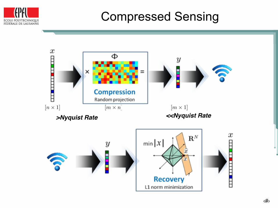
▪ Using CS it is sufficient to collect M (<<N) linear random measurements (samples)
▪ Then, can be recovered by solving the convex optimization problem: €
yM ×1
=ΦM ×N⋅ x
N×1
Measurement vector Original ECG vector
Measurement/Sensing matrix (Gaussian random matrix)
€
α
€
min˜ α ∈ℜN
˜ α 1
Subject to:
€
ΦΨ ˜ α − y2≤σ
Compressed sensing (CS) is a new low-complexity sensing and compression paradigm for sparse signals

© EPFL 2015 15
▪ Using CS it is sufficient to collect M (<<N) linear random measurements (samples)
▪ Then, can be recovered by solving the convex optimization problem: €
yM ×1
=ΦM ×N⋅ x
N×1
Measurement vector Original ECG vector
Measurement/Sensing matrix (Gaussian random matrix)
€
α
€
min˜ α ∈ℜN
˜ α 1
Subject to:
€
ΦΨ ˜ α − y2≤σ
Compressed sensing (CS) is a new low-complexity sensing and compression paradigm for sparse signals
CS is attractive for real-time ECG compression on resource-constrained WBSN, but what about biosignal degradation due to CS reconstruction (in real-time)?
‹#›
Compressed Sensing
>Nyquist Rate <<Nyquist Rate[m⇥ n][n⇥ 1] [m⇥ 1]

‹#›
Compressed SensingSi
mpl
e En
code
rCo
mpl
ex d
ecod
er
>Nyquist Rate <<Nyquist Rate[m⇥ n][n⇥ 1] [m⇥ 1]

‹#›
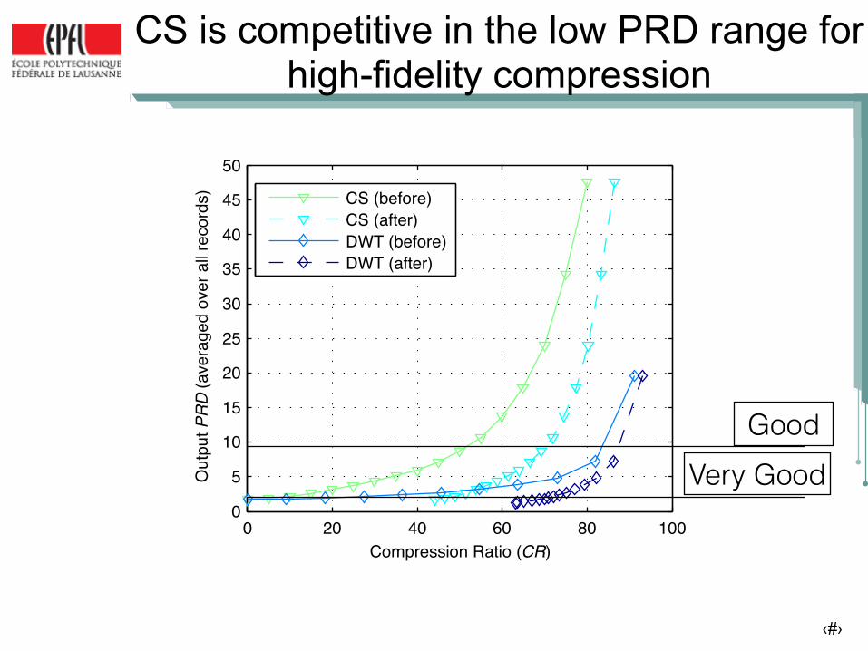
Database, performance metrics and comparison
▪ MIT-BIH Arrhythmia database: ▪ Contains 48 half-hour excerpts of two-channel
ambulatory ECG recordings ▪ Reference database for ECG compression studies
▪ Percentage Root Mean Square Difference (PRD) is defined as:
PRD Reconstructed Signal Quality0 ∼ 2% ”Very good” quality2 ∼ 9% ”Very good” or ”good” quality
9% < Not possible to determine the quality group

‹#›
CS is competitive in the low PRD range for high-fidelity compression
0 20 40 60 80 1000
5
10
15
20
25
30
35
40
45
50
Compression Ratio (CR)
Out
put PRD
(ave
rage
d ov
er a
ll rec
ords
)
CS (before)CS (after)DWT (before)DWT (after)
GoodVery Good
‹#›
CS is competitive in the low PRD range for high-fidelity compression
0 20 40 60 80 1000
5
10
15
20
25
30
35
40
45
50
Compression Ratio (CR)
Out
put PRD
(ave
rage
d ov
er a
ll rec
ords
)
CS (before)CS (after)DWT (before)DWT (after)
0 20 40 60 80 1000
5
10
15
20
25
30
35
40
45
50
Compression Ratio (CR)
Out
put PRD
(ave
rage
d ov
er a
ll rec
ords
)
CS (before)CS (after)DWT (before)DWT (after)
GoodVery Good

© EPFL 2015
CS-based ECG WBSN (only 30% of ECG data kept)
19
See video at: http://esl.epfl.ch/page-42817.html

© EPFL 2015
CS provides over a 23-fold reduction in execution time, but only 10% node lifetime extension
20
0
150
300
450
600
DWT CS
30%
1.3%
Code execution time

© EPFL 2015
CS provides over a 23-fold reduction in execution time, but only 10% node lifetime extension
20
0
150
300
450
600
DWT CS
30%
1.3%
Code execution time
23 x

© EPFL 2015
Node lifetime
134.6 h147 h
0
37.5
75
112.5
150
DWT CS No compression
107 h
CS provides over a 23-fold reduction in execution time, but only 10% node lifetime extension
20
0
150
300
450
600
DWT CS
30%
1.3%
Code execution time
23 x

© EPFL 2015
Node lifetime
134.6 h147 h
0
37.5
75
112.5
150
DWT CS No compression
107 h
CS provides over a 23-fold reduction in execution time, but only 10% node lifetime extension
20
0
150
300
450
600
DWT CS
30%
1.3%
Code execution time
23 x
~10%

© EPFL 2015
Node lifetime
134.6 h147 h
0
37.5
75
112.5
150
DWT CS No compression
107 h
CS provides over a 23-fold reduction in execution time, but only 10% node lifetime extension
20
0
150
300
450
600
DWT CS
30%
1.3%
Code execution time
23 x
~10%
Limited gains because the used generic microcontroller is not optimized for ultra-low power DSP and CS-based
operations in biological signals

© EPFL 2015 21
▪ FIRAT/TamaRISC: Inspired on PIC24 ▪ 16-bit RISC, simple 3-stage pipeline ▪ Drastically reduced to 25 types of instructions
(added CS execution support) ▪ 1 cycle/inst., Immediate branch, full data bypass ▪ Minimal ALU: ADD, SUB, AND, OR, XOR, Shift, Mult.
▪ Minimal area/power for biosignals processing ▪ Less than 5% of an embedded platform (< 10 kGE) ▪ Low-power computing: ~10 MHz (180MHz@1V)
Dicle (umcL 180nm)
Firat (umcL 90nm)
Simplicity is the key: A new generation of ultra-low-power processing cores for WBSNs
[Dogan et al., DATE 2012]

© EPFL 2015 21
▪ FIRAT/TamaRISC: Inspired on PIC24 ▪ 16-bit RISC, simple 3-stage pipeline ▪ Drastically reduced to 25 types of instructions
(added CS execution support) ▪ 1 cycle/inst., Immediate branch, full data bypass ▪ Minimal ALU: ADD, SUB, AND, OR, XOR, Shift, Mult.
▪ Minimal area/power for biosignals processing ▪ Less than 5% of an embedded platform (< 10 kGE) ▪ Low-power computing: ~10 MHz (180MHz@1V)
Dicle (umcL 180nm)
Firat (umcL 90nm)
Firat ASIC vs. 1chf coin
Simplicity is the key: A new generation of ultra-low-power processing cores for WBSNs
[Dogan et al., DATE 2012]
… And on a finger tip!

© EPFL 2015 22
Simplicity is the key: TamaRISC processing core and memories
[Dogan et al., DATE 2012]
Chip Layout
DM DM
DMIM
▪ Specialized 16-bit RISC for biosignals ▪ But memories are key: 50% energy

© EPFL 2015 22
Simplicity is the key: TamaRISC processing core and memories
[Dogan et al., DATE 2012]
Chip Layout
DM DM
DMIM
▪ Low-voltage multi-banked memories ▪ 32-kB instruction memory (IM) ▪ 36-kByte data memory (DM)
[Dogan et al., DATE 2013]
▪ Specialized 16-bit RISC for biosignals ▪ But memories are key: 50% energy

© EPFL 2015
TamaRISC: Experimental results
23
(*) 1-package compression (512 samples)
TamaRISC only 38% of MSP430 cycles due to architecture specialization and low voltage operation

© EPFL 2015
TamaRISC: Experimental results
23
(*) 1-package compression (512 samples)
TamaRISC only 38% of MSP430 cycles due to architecture specialization and low voltage operation
TamaRISC vs Firat: Faster and 30% extra power savings due to full data bypass, CS support and low-power encoding

© EPFL 2015
TamaRISC: Experimental results
23
(*) 1-package compression (512 samples)
TamaRISC only 38% of MSP430 cycles due to architecture specialization and low voltage operation
TamaRISC vs Firat: Faster and 30% extra power savings due to full data bypass, CS support and low-power encoding
Can the users finally see the benefit of CS and holistic optimization at system-level?

© EPFL 2015
CS and biosignals algorithms analysis show true advantages on ultra-low-power (ULP) processors
24
Lifetime (in hours)

© EPFL 2015
CS and biosignals algorithms analysis show true advantages on ultra-low-power (ULP) processors
24
▪ Feasible to develop long-lasting smart WBSN nodes that interact with smartphones ▪ Adapts at run-time to patient’s heart ▪ Automatic detection of arrhythmias ▪ Real-time notification to doctors
Lifetime (in hours)

© EPFL 2015
CS and biosignals algorithms analysis show true advantages on ultra-low-power (ULP) processors
25See video at: http://www.smartcardia.com

© EPFL 2015
Smart ULP WBSN designs can reach resonance in the media, but also impact in medical community!
26
Non-intrusive, light and can reduce visits by 50-60% for patients
(4-week test)

© EPFL 2015
CAN WE DO BETTER?
Next-Generation: “Really Smart” (or just Smarter) WBSN for Healthcare
27
Bio-signals- ECG - Blood pres. - EEG - Respiration - Movements
Sensing Processing Transmit
Peripherals
Instruction memory Processor Data
memory
Diagnose, Abnormality, Analysis …
Output:
WBSN

© EPFL 2015
CAN WE DO BETTER?
Next-Generation: “Really Smart” (or just Smarter) WBSN for Healthcare
27
Bio-signals- ECG - Blood pres. - EEG - Respiration - Movements
Sensing Processing Transmit
Peripherals
Instruction memory Processor Data
memory
Diagnose, Abnormality, Analysis …
Output:
WBSN
- Selective DSP (Classification) - Multi-lead Compression SW
- Ultra-low Power (ULP) architectures - Hybrid CS-based front end designHW
Core Core
Core Core
Core Core
Let’s exploit BIG DATA!

‹#›
Outline
Software ▪ On-node compression
▪ Selective advanced ECG analysis ▪ Multi-lead compression ▪ Robust Compressed Sensing
Hardware ▪ CS-based Analog to Information
▪ ECG ultra-low-power front-end design
© EPFL 2015 29
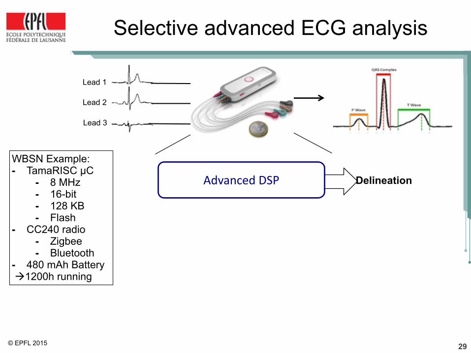
Selective advanced ECG analysis
Lead 1
Lead 2
Lead 3
WBSN Example: - TamaRISC µC
- 8 MHz - 16-bit - 128 KB - Flash
- CC240 radio - Zigbee - Bluetooth
- 480 mAh Battery !1200h running
DelineationAdvanced(DSP

© EPFL 2015 29
Selective advanced ECG analysis
Lead 1
Lead 2
Lead 3
YES “Report Normal”
NO“Activate Advanced DSP”
Normal'Situation?
WBSN Example: - TamaRISC µC
- 8 MHz - 16-bit - 128 KB - Flash
- CC240 radio - Zigbee - Bluetooth
- 480 mAh Battery !1200h running
DelineationAdvanced(DSP
Possible Selective Activation?

© EPFL 2015
Classification of Heartbeats
30
▪ Normal condition
▪ Normal heartbeat morphology
▪ Classif. heartbeats ▪ Problem dimensionality ▪ Very complex existing
algorithms
YES “Report Normal”
NO“Activate Advanced DSP”
Normal'Situation?
DelineationAdvanced(DSP
Heartbeat detection CLASSIFIER

© EPFL 2015
Classification of Heartbeats
30
▪ Normal condition
▪ Normal heartbeat morphology
▪ Classif. heartbeats ▪ Problem dimensionality ▪ Very complex existing
algorithms
YES “Report Normal”
NO“Activate Advanced DSP”
Normal'Situation?
DelineationAdvanced(DSP
Heartbeat detection CLASSIFIER
Light-weight embedded heartbeat classifier 1. Random Projection (RP) dimensionality reduction 2. Embedded Neuro-Fuzzy classifier (NFC)
© EPFL 2015
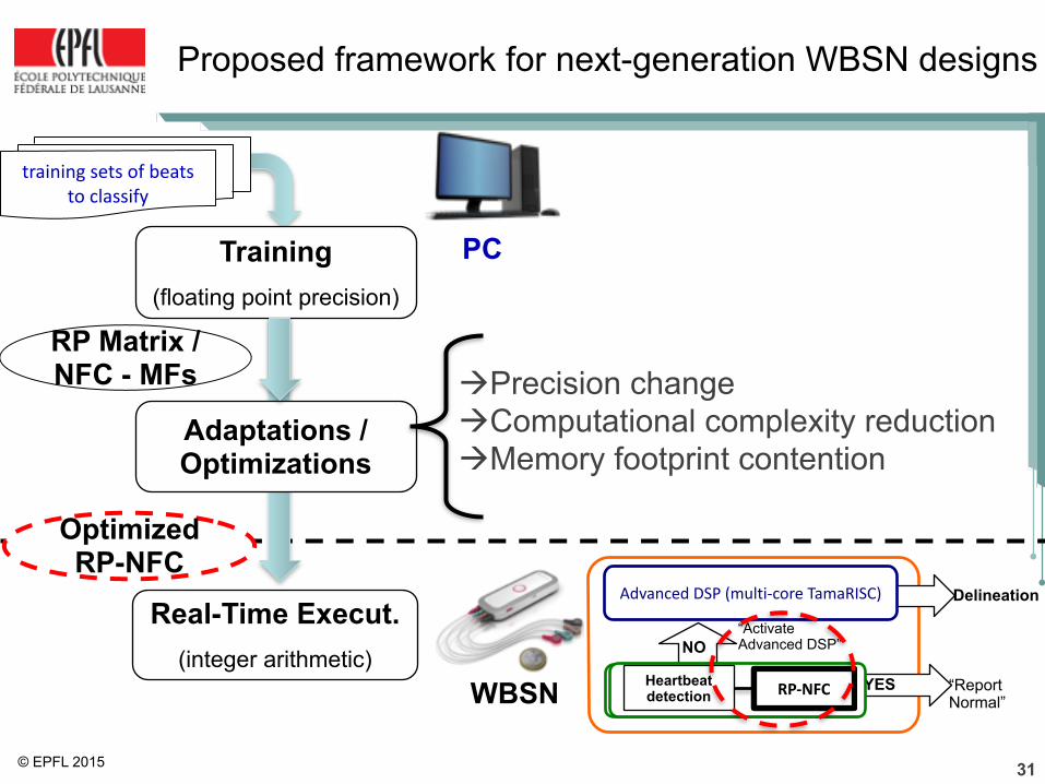
Proposed framework for next-generation WBSN designs
31
!Precision change!Computational complexity reduction!Memory footprint contention
Real-Time Execut. (integer arithmetic)
Training (floating point precision)
Adaptations / Optimizations
PC
WBSN
training(sets(of(beats( to(classify
RP Matrix / NFC - MFs
YES “Report Normal”
NO“Activate Advanced DSP”
Normal'Situation?
DelineationAdvanced(DSP((multi9core(TamaRISC)
Heartbeat detection CLASSIFIERRP6NFC
Optimized RP-NFC

© EPFL 2015
Initial Case study: Smarter ECG Monitor
32
YES “Report Normal” (1 point per heartbeat)
NO “Activate Advanced DSP”
Normal'Situation?
Delineation (9 points per heartbeat)
Advanced(DSP
83%
17%
Typical ECG Monitor
12%18%
70%
Smarter ECG Monitor
Advanced DSP Extension Idle Time
Duty Cycle▪ Duty cycle reduction of 65% for MIT-BIH DB▪ Transmission or storage reduction of 68%
▪ In a real test with multi-core WBSN node ! Energy savings of 23%
Heartbeat detection RP6NFC
Up to 61.5 days of operation (~1476 hours), finally we got
our ULP WBSN!
‹#›
Outline
Software ▪ On-node compression
▪ Single-lead compression ▪ Multi-lead compression ▪ Robust Compressed Sensing
Hardware ▪ CS-based Analog to Information
▪ ECG ultra-low-power front-end design
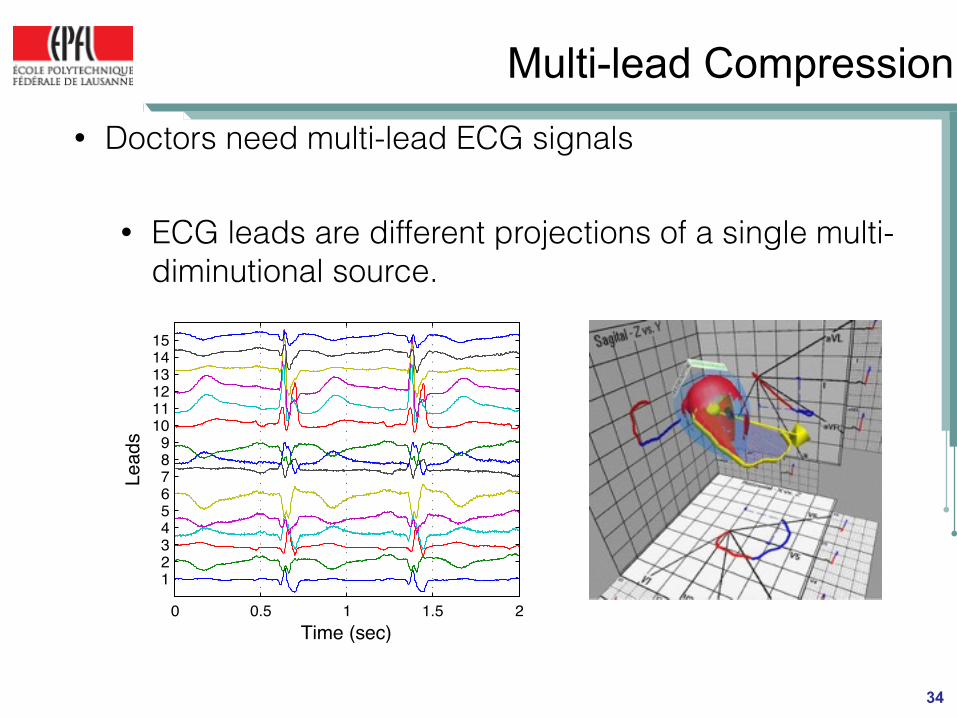
Multi-lead Compression• Doctors need multi-lead ECG signals
• ECG leads are different projections of a single multi-diminutional source.
34
0 0.5 1 1.5 2
123456789
101112131415
Lead
s
Time (sec)

Joint Sparsity Structure
0 0.5 1 1.5 2
123456789
101112131415
Lead
s
Time (sec)100 200 300 400 500
1
5
10
15
Sample Number
lead
s N
umbe
r
Multi-lead ECG sparse wavelet coefficients
• Strong similarity exist between support of sparse representation among leads.
• Required measurements in normal CS
35
m = O(s log ns )
To embed the location of non-zeros

Joint Sparsity Structure
0 0.5 1 1.5 2
123456789
101112131415
Lead
s
Time (sec)100 200 300 400 500
1
5
10
15
Sample Number
lead
s N
umbe
r
Multi-lead ECG sparse wavelet coefficients
35
minα∈!N
A1 ΦΨA! − y
2≤ σsubject to:CS:

Joint Sparsity Structure
0 0.5 1 1.5 2
123456789
101112131415
Lead
s
Time (sec)100 200 300 400 500
1
5
10
15
Sample Number
lead
s N
umbe
r
Multi-lead ECG sparse wavelet coefficients
35
minα∈!N
A1 ΦΨA! − y
2≤ σsubject to:CS:
minα∈!N
A1,2 ΦΨA! − y
2≤ σsubject to:Joint comp:

Joint Compression: Results
• 7% improvement of Compression ratio36
0 20 40 60 80 1000
VG
G
20
30
40
50
Compression Ratio (CR)
Aver
aged
SN
R o
ver a
ll re
cord
72.765.9
Normal ReconstructionJoint Reconstruction
Good
Joint Reconstruction -group sparsityPRD

Power Consumption breakdown
Normal CS
Joint Compression
Energy [uJ]0 12.5 25 37.5 50
RadioCode executionSampling + OS
8
11
6
6
17
25
• 26% node lifetime extension on top of normal CS (Shimmer Platform)
37
• Power consumption comparison

‹#›
Outline
Software ▪ On-node compression
▪ Single-lead compression ▪ Multi-lead compression ▪ Robust Compressed Sensing
Hardware ▪ CS-based Analog to Information
▪ ECG ultra-low-power front-end design

Hybrid Memory on a Multi-core Processor• Use of reliable Standard Cell
(SC) Memories (SCMEM) allows scaling to lower supple voltage, but in cost of large area penalties.
• Use of 6 Transistor SRAM (6T) cell memories are not reliable in supply voltage scaling.
• Ultra-low power multi-core architecture for multi-channel bio-signal processing.
• Hybrid memory architecture with 6T SRAM and SCMEM working on a aggressive voltage scaling.
39
AFESamples Buffer (SB)
. . . S1 S2 S3 SN
S1 S2 S3 SN
ECGleads
(samples vectors)
. . .
6T/SCMEMTCDM
MB#0
PE#0
IM
SCMEM 6T SRAM
MB#15
PE#7
IM
LIC
MBSC0 MB6T
0 MBSC15 MB6T
15
Architecture designed by university of Bologna

Robust Compressed Sensing
40
Sensing Matrix is stored in 6TMEMs
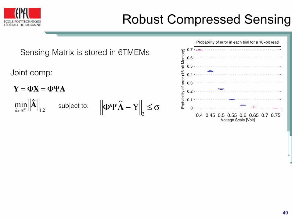
Robust Compressed Sensing
40
0
0.1
0.2
0.3
0.4
0.5
0.6
0.7
0.4 0.45 0.5 0.55 0.6 0.65 0.7 0.75Voltage Scale [Volt]
Probability of error in each trial for a 16−bit read
Prob
abilit
y of
erro
r (16
bit
Mem
ory)Sensing Matrix is stored in 6TMEMs
minα∈!N
A1,2 ΦΨA! −Y
2≤ σsubject to:
Joint comp:
Y = ΦX = ΦΨA

Robust Compressed Sensing
400.4 0.45 0.5 0.55 0.6 0.65 0.7 0.750
0.2
0.4
0.6
0.8
1
Voltage scale [V]
Prob
abilit
y of
erro
r rec
onst
ruct
ion
L = 15L = 30L = 45L = 60
0
0.1
0.2
0.3
0.4
0.5
0.6
0.7
0.4 0.45 0.5 0.55 0.6 0.65 0.7 0.75Voltage Scale [Volt]
Probability of error in each trial for a 16−bit read
Prob
abilit
y of
erro
r (16
bit
Mem
ory)Sensing Matrix is stored in 6TMEMs
minA! ,E!
A1,2+ λ E
1(Φ + E)ΨA! −Y
2≤ σs.t:
Robust Compressed Sensing
Y = (Φ +E)X = (Φ +E)ΨA
Joint comp with Error:
minα∈!N
A1,2 ΦΨA! −Y
2≤ σsubject to:
Joint comp:
Y = ΦX = ΦΨA
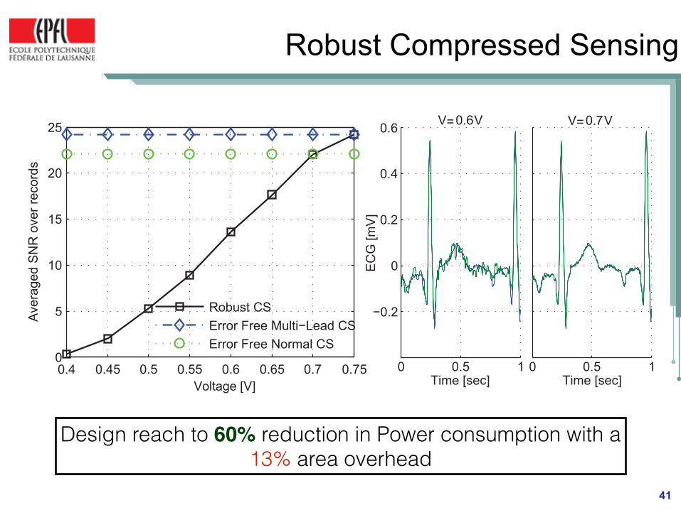
Robust Compressed Sensing
41
Design reach to 60% reduction in Power consumption with a 13% area overhead

‹#›
Outline
Software ▪ On-node compression
▪ Single-lead compression ▪ Multi-lead compression ▪ Robust Compressed Sensing
Hardware ▪ CS-based Analog to Information
▪ ECG ultra-low-power front-end design

‹#›
CS-based A2I
▪ Why analog implementation?
RadioSampling Compression

‹#›
CS-based A2I
▪ Why analog implementation?
RadioCompressed Sensing

‹#›
CS-based A2I
▪ Why analog implementation?
▪ Ultra-wide band Signal Processing−Huge burden on sampling devices is not
manageable
RadioCompressed Sensing

‹#›
CS-based A2I
▪ Why analog implementation?
▪ Ultra-wide band Signal Processing−Huge burden on sampling devices is not
manageable
RadioCompressed Sensing

‹#›
CS-based A2I
▪ Why analog implementation?
▪ Ultra-wide band Signal Processing−Huge burden on sampling devices is not
manageable▪ Power-aware sensing
−By merging sampling and compression and thus removing large part of readout and digital processing part.
RadioCompressed Sensing

‹#›
Random Modulator
▪ Signal Model:
▪ Random Modulator
x(t) =nX
i=1
↵i�i(t)
@Nyquist Freq. @Below Nyquist Freq.
Pc(t) = pi, t 2hin ,
(i+1)n
⌘i = 0, 1, . . . , n� 1
m⇥ Analog Filter
h(t)- - -r��✓rp(t)
x(t).p(t)t = n
M
6
-x(t)y[n]
1
z(t)
R

‹#›
Analog CS: RMPI
▪ Limitations: ▪ Exact representation of the digital CS means that
number of channels should be equal to the number of measurements.
▪ Random modulation (mixers) should work at Nyquist Frequency
▪ higher number of channels is not practical!
x(t)-
- m⇥-h(t) -��✓ -
y1[i]
6p1(t)
t = iCm
- m⇥-h(t) -��✓ -
y2[i]
6p2(t)
t = iCm
- m⇥-h(t) -��✓ -
yC [i]
6pC(t)
t = iCm
rrr
1
• RMPI: Random Modulator Pre-Integrator
• parallel RM channels
• Further reducing ADC rate
• Less measurement

‹#›
Analog CS: RMPI
• New Architecture proposed to reduce number of channels in RMPI architecture and reduce random modulation called SRMPI.
• The design is for highly sparse signals
• RMPI: Random Modulator Pre-Integrator
• parallel RM channels
• Further reducing ADC rate
• Less measurement
x(t)
r(t)
- m⇥ -
6
SRMPI
- m⇥-h(t) -��✓ -
y1[i]
6p1(t)
t = iCm
- m⇥-h(t) -��✓ -
y2[i]
6p2(t)
t = iCm
- m⇥-h(t) -��✓ -
yC [i]
6pC(t)
t = iCm
rrr
1

‹#›
Hardware Optimization: Analog CS
▪ 8-channel RMPI/SRMPI reconfigurable design are implemented ▪ Main board + 8 RM daughter board for each channel
▪ Connected to PC with DAC for reconfiguration and communication
▪ SRMPI pre-modulation are implemented on main board (bypassed for RMPI)
▪ modulation (CMOS Switch)
▪ Integrator (Analog filter)
▪ ADC
8-channel Implementation of Analog CS

‹#›
Experimental Results
▪ Signal model: 3 tone (sinusoid)
−10 0 10 20 30 40 50 6020
30
40
50
60
70
80
90
100
110
120
SNRin(dB)
SNR o
ut(dB)
SRMPI, M = 64RMPI , M = 64SRMPI, M = 32RMPI , M = 32
8163264 128 256 512 1024
0
20
40
60
80
100
120
140
M
SNR ou
t(dB)
SNRIN = 60 dB
SNRIN = 40 dB
SNRIN = 20 dB
SNRIN = −5 dB
RMPISRMPI

‹#›
Power break-down
0 0.5 1 1.50
5
10
15Energy Consumption
11.1635 nJ
Time [µs]
P[m
W]
0 0.5 10
5
10
Energy Consumption
0.29358 nJ
Time [µs]
P[m
W]
• Power consumption of main blocks • ADC • Mixer (modulator)

‹#›
Power break-down
▪ 63% and 75% Reduction in power consumption by RMPI and SRMPI respectively.
▪ SRMPI outperforms RMPI by at least 25%.
• Power consumption of main blocks • ADC • Mixer (modulator)
Ener
gy [u
J]
0
1.5
3
4.5
6
Nyquist Sampling RMPI SRMPI
ADC Switch
0.81.20.7150.715
5.716

‹#›
Outline
Software ▪ On-node compression
▪ Single-lead compression ▪ Multi-lead compression ▪ Robust Compressed Sensing
Hardware ▪ CS-based Analog to Information
▪ ECG ultra-low-power front-end design

50
• New hybrid digital+analog design is proposed
• Parallel low resolution channel
• High resolution RMPI channel
Hybrid CS-based Front-end
1 - Channel ECG
-Compressed Sensing
-
CSdata
-Low Resolution ADC
-
Low
Res.
-
-
Transmit
-
1
0 0.5 1900
950
1000
1050
1100
1150
1200
1250
sec
Raw
ADC
Sam
ples
Original ECGLow Resolution ECG

50
• New hybrid digital+analog design is proposed
• Parallel low resolution channel
• High resolution RMPI channel
Hybrid CS-based Front-end
1 - Channel ECG
-Compressed Sensing
-
CSdata
-Low Resolution ADC
-
Low
Res.
-
-
Transmit
-
1
0 0.2 0.4 0.6900
950
1000
1050
1100
1150
1200
sec
Raw
ADC
Sam
ples
Bound AreaOriginal ECG

50
• New hybrid digital+analog design is proposed
• Parallel low resolution channel
• High resolution RMPI channel
• Relaxed RIP, fewer measurements
Hybrid CS-based Front-end
1 - Channel ECG
-Compressed Sensing
-
CSdata
-Low Resolution ADC
-
Low
Res.
-
-
Transmit
-
1
min
↵2RN||˜↵||1 subject to
8<
:
||� ˜↵� y||2 �,
˙
x ↵ ˙
x+ d

Performance Quality Comparison
• 35 % reduction in compression ratio• Very good performance at higher CR (SNR = 17dB @97%)
51
50 56 62 69 75 81 88 94 970
5
10
15
20
25
Compression Ratio (%)
Aver
aged
SN
R o
ver r
ecor
ds
Hybrid CSCS
Good

Performance Quality Comparison
• 35 % reduction in compression ratio• Very good performance at higher CR (SNR = 17dB @97%)
51
0 0.5 1−0.6
−0.4
−0.2
0
0.2
0.4
0.6
0.8
1
sec
mV
δ = 6% − SNR = 18.7 dB
Original ECGReconstructed ECG
18.7 dB @86%
0 0.5 1−0.6
−0.4
−0.2
0
0.2
0.4
0.6
0.8
1
sec
mV
δ = 12% − SNR = 19.7 dB
Original ECGReconstructed ECG
19.7 dB @80%

Power consumption break-down• Power break down
52
10−4
10−3
10−2
10−1
100
101
102
10−4
10−2
100
102
104
106
108
1010
Sampling Frequency (MHz)
Anal
og C
S Po
wer
Con
sum
ptio
n [µ
W]
P [adc]P [Int]P [amp]P [Total]
2.5 X Power reduction compared to RMPI at Good quality 11 X reduction at SNR = 17dB (number of channels = 16)

© EPFL 2015
Conclusion
▪ Smart ULP WBSN nodes needed to enable new healthcare ▪ Feasible to do real-time automated biosignals analysis▪ Communication not always the worst part: sensing and processing
▪ Knowledge about target bio-signals not to over-design WBSNs • Compressed sensing very powerful approach (if used with care)• Removes need for complex instructions sets and limits memory use
▪ New ULP WBSN multi-parametric architectures coming up▪ Adaptive to each patient (big data link!)▪ Joint compressive sensing can help to significantly save power
▪ Novel field: wearable multimodal biosignal systems▪ Develop uses of these new WBSNs to monitor other emotions, etc.▪ Design methods to ease low-power software mapping needed!
53

© EPFL 2015 54
Thank You
QUESTIONS? ObeSense, BodyPowerSense, BioCS Projects in Nano-Tera.ch
PHIDIAS and ICT energy
Acknowledgments:
Thanks to our great collaborators: LTS2-EPFL, TCL-EPFL and IIS-ETHZ
© EPFL 2015
Key References and Bibliography
55
▪ CS-based ECG Compression and implementation • H. Mamaghanian, N. Khaled, D. Atienza, P. Vandergheynst, “Compressed Sensing for
Real-Time Energy-Efficient ECG Compression on Wireless Body Sensor Nodes”, IEEE Trans. on Biomedical Engineering (TBME), 2011
• K. Kanoun, H. Mamaghanian, N. Khaled, D. Atienza, “A Real-Time Compressed Sensing-Based Personal Electrocardiogram Monitoring System”, Proc. DATE, 2011.
• H. Mamaghanian, G. Ansaloni, D. Atienza, P. Vandergheynst, “Power-efficient joint compressed sensing of multi-lead ECG signals”, Proc. ICASSP, 2014
• D. Bortolotti, H. Mamaghanian, A. Bartolini, M. Ashouei, Jan Stuijt, D. Atienza Alonso, P. Vandergheynst, L. Benini, “Approximate compressed sensing: ultra-low power biosignal processing via aggressive voltage scaling on a hybrid memory multi-core processor”, Proc. ISLPED 2014,
• H. Mamaghanian, P. Vandergheynst, “Ultra-low-power ECG front-end design based on compressed sensing”, Proc. DATE, 2014
▪ ULP WBSN computation optimization and ECG application mapping • F. Rincon, J. Recas, N. Khaled, D. Atienza, “Development and Evaluation of Multi-Lead
Wavelet-Based ECG Delineation Algorithms for Embedded Wireless Sensor Nodes”, IEEE Trans. on Information Technology in BioMedicine (TITB), Nov. 2011

© EPFL 2015
▪ ULP biosignal analysis and optimization • R.Braojos, I. Beretta, G. Ansaloni, D. Atienza, “Early Classification of Pathological
Heartbeats on Wireless Body Sensor Nodes”, MDPI Sensor, vol. 14, Nr. 11, Dec. 2013. • R. Braojos, G. Ansaloni, D. Atienza, “A Methodology for Embedded Classification of ECG
Beats Using Random Projections”, Proc. of DATE, 2013. • H. Mamaghanian, N. Khaled, D. Atienza, P. Vandergheynst, “Design and Exploration of
Low-Power Analog to Information Conversion Based on Compressed Sensing”, IEEE Journal on Emerging and Selected Topics in Circuits and Systems (JETCAS), Sept. 12.
• N. Boichat, N. Khaled, F. Rincon, D. Atienza, “Wavelet-Based ECG Delineation on a Wearable Embedded Sensor Platform”, Proc. BSN, 2009.
▪ WBSN Technologies and Components • F. Rincón, M. Paselli, J. Recas, et al., “OS-Based Sensor Node Platform and Energy
Estimation Model for Health-Care Wireless Sensor Networks”, Proc. DATE, 2008. • Y. Lee, et. al., “A Modular 1mm3 Die-Stacked Sensing Platform with Optical
Communication and Multi-Modal Energy Harvesting,” IEEE ISSCC, 2012. • N. Verma, et. al., “A High-Density 45nm SRAM Using Small-Signal Non-Strobed
Regenerative Sensing,” IEEE JSSC, vol. 44, no. 1, Jan. 2009. • Y. Lee, et. al., “A 5.42nW/kB Retention Power Logic-Compatible Embedded DRAM with
2T Dual-Vt Gain Cell for Low Power Sensing Application,” IEEE ASSCC, 2010. • M. Seok, et. al., “The Phoenix Processor: A 30pW Platform for Sensor Applications,”
IEEE Symp. on VLSI Circuits, 2008.
Key References and Bibliography
56
© EPFL 2015
Key References and Bibliography
57
▪ Single- vs. multi-core WBSN platform design • A. Y. Dogan, R. Braojos Lopez, J. Constantin, G. Ansaloni, et al., “Synchronizing Code
Execution on Ultra-Low-Power Embedded Multi-Channel Signal Analysis Platforms”. Proc. DATE, 2013.
• A. Y. Dogan, J. Constantin, M. Ruggiero, D. Atienza, et al., “Multi-Core Architecture Design for Ultra-Low-Power Wearable Health Monitoring Systems”, Proc. DATE, 2012.
• J. Constantin, A. Y. Dogan, O. Andersson, P. Meinerzhagen, J. Rodrigues, et al. “TamaRISC-CS: An Ultra-Low-Power Application-Specific Processor for Compressed Sensing”, Proc. VLSI-SoC, 2012.