ultra high temperature latent heat energy storage and
TRANSCRIPT
Ultra high temperature latent heat energy storage
and thermophotovoltaic energy conversion
Alejandro Datas(*)
, Alba Ramos, Antonio Martí, Carlos del Cañizo and Antonio Luque
Instituto de Energía Solar – Universidad Politécnica de Madrid, Madrid, 28040, Spain
(*) corresponding autor: [email protected]
Keywords: LHTES (latent heat thermal energy storage), high temperature, thermophotovoltaics,
silicon, boron, PCM (phase change materials), CSP (concentrated solar power).
Abstract
A conceptual energy storage system design that utilizes ultra high temperature phase change
materials is presented. In this system, the energy is stored in the form of latent heat and converted to
electricity upon demand by TPV (thermophotovoltaic) cells. Silicon is considered in this study as
PCM (phase change material) due to its extremely high latent heat (1800 J/g), melting point
(1410ºC), thermal conductivity (~25 W/m-K), low cost (less than $2/kg or $4/kWh) and abundance
on earth. The proposed system enables an enormous thermal energy storage density of ~ 1
MWh/m3, which is 10-20 times higher than that of lead-acid batteries, 2-6 times than that of Li-ion
batteries and 5-10 times than that of the current state of the art TES systems utilized in CSP
(concentrated solar power) applications. The discharge efficiency of the system is ultimately
determined by the TPV converter, which theoretically can exceed 50%. However, realistic
discharge efficiencies utilizing single junction TPV cells are in the range of 20-45%, depending on
the semiconductor bandgap and quality, and the photon recycling efficiency. This concept has the
potential to achieve output electric energy densities in the range of 200-450 kWhe/m3, which is
comparable to the best performing state of the art Lithium-ion batteries.
Nomenclature list
cA TPV cells total area (m2)
psc heat capacity of solid PCM (J/g-K)
plc heat capacity of liquid PCM (J/g-K)
c speed of light (m/s)
E radiative energy flux (W/m2-sr)
totE energy stored instantaneously in the PCM in the form of specific and latent heat (J)
h Plank constant (Js)
k Boltzmann constant (J/K)
lk thermal conductivity of liquid PCM (W/m-K)
sk thermal conductivity of solid PCM (W/m-K)
L container length (m)
fL latent heat (J/g)
N photon flux (#photons/m2-sr-sec)
sn refraction index of the semiconductor
elP TPV output electrical power (W)
lQ heat flux in the liquid PCM (W)
sQ heat flux in the solid PCM (W)
1R distance from center to the emitter (m)
2R distance from center to the outer container wall (m)
mr distance from center to the solid-liquid front (m)
t time (s)
1T temperature at the emitter (K)
2T temperature at PCM-wall boundary (K)
mT melting temperature of PCM (K)
cT TPV cells temperature (K)
V TPV cell voltage (V)
G TPV cell semiconductor bandgap (eV)
photon energy (eV)
density (g/m3)
BR reflectivity of the back-surface reflector in TPV cell
int internal photoluminescence quantum efficiency of the TPV cell
ext external photoluminescence quantum efficiency of the TPV cell

1 Introduction
LHTES (latent heat thermal energy storage) employs energy to cause the phase change transition in
a material that subsequently stores energy in the form of latent heat. That material is referred to as
PCM (phase change material) and is the key element determining the overall performance of the
storage system. PCMs promises one of the highest energy densities and lowest costs of existing
TES materials [1], [2]. However, current LHTES solutions are subject to a very low heat extraction
rate from the storage medium, which is attributed to the low solid-phase thermal conductivity and
moderate latent heat of PCMs. Current research efforts focus on developing relatively sophisticated
PCM encapsulation so that thermal conductivity is notably enhanced [1], [3]–[6]. However, these
strategies inherently have a lower energy density potential, since part of the volume is dedicated to
the PCM host.
An alternative solution consists of directly using PCMs with higher thermal conductivity and latent
heat. As a general rule, the heat of fusion of materials increases with melting temperature [1], [7];
thus, there is an interest on moving towards higher melting point PCMs. However, in TES for
power generation there is a maximum temperature imposed by the heat transfer fluid (HTF) that is
used to carry the heat from the PCM to the heat engine, which degrades at high temperatures.
Maximum temperatures are typically below 500 ºC [8]. Other technological options exist though;
such as thermophotovoltaics (TPV) [9], [10], thermionic [11] or hybrid thermionic-photovoltaic
[12] devices that do not require HTFs and consequently have the potential to operate at
extraordinary high temperatures.
Previous works have proposed conceptual system designs for solar thermal energy storage based on
very high melting point PCMs, such as pure silicon and boron (melting points of 1410ºC and
2076ºC, respectively) and TPV converters [13]–[19]. The first experiments on molten silicon for
TES applications have been recently carried out at the University of South California with the aim
of developing a solar thermal propulsion system for microsatellites [20]. The container damage due
to freezing expansion of pure silicon was the most relevant engineering concern. Besides, a highly
asymmetric freezing profile was observed due to the use of non-adiabatic container walls, which
produced regions of molten silicon encased in solid silicon that ultimately resulted in high stress
and container damage. It is worth noting that these issues could be solved in future designs by
several means, such as using quasi-adiabatic container walls, i.e. improved container thermal
insulation, or reducing the container fill factor [20]. In the opinion of the authors, an especially
interesting solution consists on using silicon alloys instead of pure silicon, in order to reduce the

freezing expansion coefficient of the PCM. We believe that, among all the possibilities, the silicon-
boron system is particularly interesting due to the extremely high latent heat of boron (4650 J/g) and
the moderately low melting temperature (1385ºC) for the eutectic Si0.92B0.08 [21], [22]. Besides, the
silicon lattice parameter contracts upon alloying with boron [21], which suggests that freezing
expansion issues could be eliminated. Other practical concern is the thermo-chemical compatibility
between the container and the PCM at those high temperatures. A variety of refractory materials
have been extensively used for casting solidification of all kind of metals at high temperatures,
including silicon and boron. Some examples are BN (used in [20]) SiC and Si3N4. In these cases,
important selection criteria are the wetability, solubility and reactivity of the container with the
PCM, along with evaporation and oxidation of the PCM in oxygen-rich atmospheres. Thus, it is still
needed an extensive research on the compatibility of these materials for the particular application of
LHTES, especially concerning cycling and long term reliability.
In this work we present a conceptual LHTES system design for both S2H2P (solar-to-heat-to-
power), commonly referred to as CSP (concentrated solar power), and P2H2P (power-to-heat-to-
power) applications. Notice that other P2H2P concepts have been previously proposed to store the
excess of electricity in the grid and co-generate heat and electricity [23]. The concept presented in
this paper is based on the same operation principles than previously proposed systems in [13]–[19],
i.e. high temperature PCM and TPV energy conversion. The proposed system differentiates from
the previous designs in its geometrical configuration, which facilitates the thermal insulation of the
PCM and the integration of an independent (mobile) TPV generator, providing a tunable power
discharge rate (from zero to full-discharge mode). We assess this concept theoretically to predict its
performance under several assumptions, which range from idealistic (to provide the upper bounds
of this concept) to more realistic, to provide its actual short-term potential.
2 System description
Figure 1 shows two possible configurations of the LHTES system presented in this paper for P2H2P
[24] (left-hand side) and S2H2P or CSP (right-hand side) applications. In the P2H2P case, an
electric heating system is used for melting the PCM. Among all the possible options, an inductive
electric heater could be used if the PCM is magnetic or electrically conductive (e.g. iron or
metallurgical silicon). Other options include resistive or microwave heating. In any case, electrical
energy is stored in the form of the latent heat within the PCM. In the S2H2P case (right-hand side in
Figure 1); concentrated solar power heats the inner walls of the vessel containing the PCM. If the
sunlight concentration factor is high enough [13], [14] (above 1000 suns) the solar heat will produce

the melting of the PCM and consequently, solar energy will be stored in the form of latent heat.
Other arrangements not illustrated in this paper may use the waste heat from high temperature
industrial processes or other kinds of electric heating.
In both cases of Figure 1 the stored heat is released in the form of electricity by using a TPV
converter, which comprises a number of infrared sensitive photovoltaic cells that directly produce
electricity from radiant heat. In contrast to conventional heat engines, the contact-less nature of
TPV converters enable extremely high temperature operation, which is essential for this kind of
systems. Besides, TPV can provide extremely high power densities (power-to-weight and power-to-
volume ratio) at low maintenance costs (neither moving parts nor working fluids within the
converter) along with silent operation, which is important for decentralized ES applications.
Furthermore, the TPV conversion efficiency is very high, potentially exceeding 50% due to the
possibility of sub-bandgap photon recycling, which can be accomplished, for instance, by using
reflectors in the back side of the TPV cells [25].
When electricity is demanded from the LHTES system, the TPV generator is moved in the
cylindrical cavity formed by the inner walls of the vessel, from now-on referred to as emitter
(Figure 1). Then, the TPV converter is irradiated by the emitter, which is in direct contact with the
molten PCM, and produces electricity. During this process, the PCM progressively solidifies
creating a crust of solid around the emitter. This crust difficults the flow of heat from the liquid
PCM to the emitter. In this concern, the higher solid-phase thermal conductivity of silicon PCM
enormously mitigates the impact of this effect on the output system power. Notice that these
systems have the possibility of delivering not only electricity, but also heat from the TPV cells
cooling, which might be beneficial in some particular applications such as in domestic heating,
where the output coolant temperatures of 40-70ºC match perfectly with the heating temperature
requirements.
From the previous description, it is evident that the energy density (stored energy per unit of
volume) and the specific energy (stored energy per unit of weight) of these systems relies on the
latent heat of the PCM. Besides, the PCM melting temperature determines the attainable TPV
conversion efficiency and power density (W/cm2). Thus, high melting point and latent heat are
desirable. As explained above, among all the possible candidates, silicon and boron stand out as
particularly interesting materials due to their extremely high latent heats (1800 J/g and 4650 J/g,
respectively, see Figure 2). Silicon is advantageous from the practical point of view due to its higher
thermal conductivity (25-130 W/mK) and moderate melting point (1410ºC) if compared with boron

(thermal conductivity below 30 W/mK and melting point of 2076ºC) [13], [26], [27]. Besides,
silicon is abundant (second most abundant element on earth) and has low cost (~1.7 $/kg). As
described above, silicon-boron alloys are particularly interesting due to their potential to achieve
extremely high latent heat, moderate melting temperature and lower freezing expansion coefficient
than pure silicon. However, for the sake of concreteness in this paper we will use the latent heat and
thermal conductivity values of pure silicon. The analysis of other promising PCMs will be
considered in future works.
3 System model
In order to describe the transient performance of the LHTES system, we assume a quasi-1D
analytical model in which the solid-liquid interface is a moving cylinder at a distance rm(t) from the
axial center of the system (Figure 3). To solve the problem we follow the quasi-stationary approach
used in [15] assuming an adiabatic (loss-less) container and neglecting natural convection in the
liquid. Natural convection in the liquid can be disregarded, as we will see later, due to the very low
temperature gradient in the liquid silicon, which leads to a very small variation of the silicon
density. Due to the later assumption the 1D-Fourier conduction law applies to describe the heat flow
in both liquid and solid phases:
dr
dTrLkQ slsl ,, 2 (1)
By integrating (1) in the solid and liquid we obtain the following expressions for the temperatures
T1 (r=R1) and T2 (r=R2) as a function of the melting temperature (Tm)
1
1
)(ln
2 R
tr
Lk
QTT m
s
sm
(2)
)(ln
22
2tr
R
Lk
QTT
ml
lm
(3)
where ks and kl are the thermal conductivities of the solid and liquid PCM, respectively. Due to the
assumption of adiabatic container, the difference between the energy transferred from the liquid to
the solid equals the energy employed in performing the phase change of a the PCM contained in
between rm(t) and rm(t+Δt), which leads to:
)()()(2 trttrtrLLtQQ mmmlfsl (4)

where Lf and ρl are the latent heat of fusion and the density of the liquid PCM, respectively. An
additional equation is obtained analyzing the radiative exchange between the emitter surface (r=R1)
and the TPV converter. This analysis has already been done in [25] and results in the following
equation
),,,0(1
),,,(),,,0(/ 11 qVTEqVTEqVTEQBR
BRcGs
(5)
where
2
1 1/)(exp
2),,,(
3
2321
kT
d
chTE (6)
is the radiative energy flux emitted by a surface at temperature T and with chemical potential µ=qV
(being V the voltage of the TPV cells) in vacuum, in the spectral interval (ε1, ε2), in the normal
direction and per unit of solid angle. Equation (5) is valid under the assumption of sharp cut-off
TPV cell absorptivity (from 100% to 0%) at the bandgap edge (εG) and assumes a unity view factor
between the emitter and the cells and a reflector of reflectivity ρBR located on the back side of the
TPV cells.
Finally, due to adiabatic container the total energy stored in the PCM is delivered only by heat
radiation through the emitter surface, which leads to
tQtEttE stottot )()( (7)
where Etot is the total thermal energy stored in the PCM including both specific and latent heat:
2/)()()()2/( 222
2
1mfl
R
rlpll
r
Rspsstot rRLdrrrTcdrrrTcLE
m
m
(8)
Integrals in (8) can be analytically solved by introducing the expressions for Ts(r) and Tl(r) obtained
from the integration in (1):
21
21
21
2
42
1)(
1
RrLk
QTRTrdrrrT m
s
smm
r
Rs
m
(9)
5.0ln2
22
1)( 2
222
222
2
mm
l
lmm
R
rl rRr
Lk
QTrTRdrrrT
m (10)

The equations (2-5) and (7) can be solved numerically to obtain T1, T2, Ql, Qs and rm(t+Δt). Finally,
the output power from the TPV converter is given by [25]
),,,(
1
2
121)0,,,(
int
int21 qVTNnTNqVAP cG
BRsGcel
(11)
where
2
1 1/)(exp
2),,,(
2
2321
kT
d
chTN (12)
has the same meaning than E but for the photon flux instead of the energy flux, ns is the refraction
index of the semiconductor and ηint is the internal luminescent efficiency, i.e. the fraction of
electron-hole pairs that recombine radiatively within the semiconductor. In a first approximation,
the external luminescent efficiency, i.e. the fraction of electron-hole pairs that recombine radiatively
to yield a photon that ultimately escapes the TPV cell, can be obtained as a function of ηint, ns and
ρBR by:
int2 211
1
BRs
extn
(13)
4 System performance with ideal TPV cells
In this section, the TPV cells are assumed to be ideal (i.e. ηint = 1) with a bandgap of 0.5eV, which
could be manufactured for instance using InGaAsSb alloys on GaSb substrates. Under this
assumption, equations (2-5) and (7) are solved for the silicon parameters listed in Table I and Table
II.
Table III shows the model results for the discharge of the ES system with different geometries and
for two values of ρBR (the ideal case of ρBR=1 and a more realistic one of ρBR=0.8). Initial condition
is that emitter temperature equals the silicon’s melting point, so that energy is released from the
system during the silicon solidification. The system is considered discharged when all silicon is
solidified. Notice that the values in Table III refer to the full-power discharge mode, i.e. when the
TPV converter is entirely introduced in the cavity from the beginning, which provides the highest
power-to-discharge time ratio.

Notice that these results, calculated under the assumption of adiabatic container, are valid for
container walls of 10 cm and thermal conductivities below 0.01 W/m-K (small systems) and 0.001
W/m-K (large systems). These values are attainable by evacuated compounds (e.g. evacuated fibers
or vacuum multi-foil insulation). For larger conductivities, an additional solid-liquid front will
probably appear near the container wall and will distort the results obtained with this simplified
model.
From Table III we conclude that total energy densities (heat plus electricity) of ~ 1 MW/m3 and
electric energy densities of 200-600 kWh/m3 are attainable in principle, which is comparable to that
of best performing state of the art Li-ion batteries (Figure 4) [28], [29].
Figure 5 shows the output power as a function of time for the case of a LHTES system with ρBR=1,
L = 1 m, R1 = 0.2 m and R2 = 0.5 m. This particular arrangement delivers 916 kWh of energy, from
which 497 kWh is electricity and 419 kWh is heat. This amount of energy (heat plus electricity) is
enough to power 32 Spanish dwellings (average consumption of 10,500 kWh/home-year [30])
during 24 h. Smaller systems (microwave oven size) could be scaled to power one single home
dwelling one full day (see Table III).
Another interesting feature of these systems is the very high power peak at the start of the discharge
(Figure 5) in the full-power discharge mode. This peak can be used for power quality applications,
such as in UPS (uninterruptible power systems), where high power is required during short periods
of time.
Finally, Figure 6 shows the temperature profile through the PCM (in the radial direction) for the
same TES system configuration than that of Figure 5. Notice that the very low temperature gradient
in the liquid (that allows us to disregard the natural convection phenomenon) is attributed partially
to the fact that most of Qs comes from the released latent heat at the solid-liquid interface, which
makes Ql notably smaller than Qs. A fast decrease in the emitter temperature (at r = R1 = 0.2 m) is
observed during the first instants of operation. This is related to the sharp initial drop in the
electrical power shown in Figure 5. This strong drop in the emitter temperature is attributed to the
decreasing area in the direction of the heat flow and to the lower thermal conductivity of the
silicon’s solid-phase. The lower emitter temperature, which definitively affects the output electric
power, does not necessarily affect the conversion efficiency. This is true at least for TPV converters
with ρBR → 1, for which most of sub-bandgap radiation is reflected back to the emitter. In this case,
the lower emitter temperature implies a longer discharging time (due to lower radiative power)
instead of lower conversion efficiency.

5 System performance with realistic TPV cells
Realistic TPV cells are modeled in this work by introducing the internal and external
photoluminescent efficiency, ηint and ηext respectively, which account for non-radiative
recombination. The best performing III-V semiconductor based PV cells have demonstrated ηint and
ηext values above 95% and 35%, respectively [31]. However, semiconductors with non-direct
transitions between valence band and conduction band, such as silicon, have much lower
efficiencies, in the order of ηext ~ 0.1-1% [32]. Figure 7 shows the equivalency between ηext and ηint
for several values of ρBR, according to the model used in this work. From this figure we see, for
instance, that ηext = 0.01 (optimistic case for silicon) corresponds to ηint ~ 0.2.
Figure 8 shows the average conversion efficiency (during the full discharge of the system) as a
function of the TPV cell bandgap (εG) for different values of ηint and ρBR. For ideal BSR (ρBR → 1),
the conversion efficiency increases monotonically with the semiconductor’s bandgap,
independently of the internal luminescent efficiency. This is because most of the sub-bandgap
radiation is effectively reflected back to the emitter by the BSR and do not represent a loss of
energy. On the other hand, for realistic values of ρBR, there exist an optimum bandgap which
depends on both ρBR and ηint.
It is evident that high quality BSR is important for achieving high conversion efficiency. However,
even for relatively low values of ρBR ~ 0.8 we can achieve decent conversion efficiencies by
utilizing high quality (i.e. ηint > 0.95) low bandgap (below 0.75 eV) semiconductors. For instance,
by utilizing semiconductors with bandgaps in the range of 0.7-0.75eV such as GaSb or InGaAs
lattice matched to InP substrates, efficiencies in the range of 25-45% are achievable for BSR
reflectivities in the range of 80-95%. On the other hand, semiconductors with bandgaps as low as
0.5eV (e.g. InGaAsSb on GaSb substrates) are less sensitive to the BSR quality, with achievable
efficiencies in the range of 30-45% for the same values of ρBR. Notice that the impact of ηint on the
conversion efficiency is more relevant for low bandgap semiconductor, in which case having high
quality material is especially relevant. However, even for “low quality” and low bandgap
semiconductors such as germanium (0.67eV and assuming ηint ~ 0.2) we could obtain decent
efficiencies in the range of 20-35%. The lower efficiencies in this case are greatly compensated by

the lower cost of germanium substrates if compared with other III-V substrates such as InP or GaSb
(about six times cheaper).
Lastly, another possible strategy consists of using high bandgap semiconductors, in which case the
impact of ηint is less important and the conversion efficiency depends mostly on the BSR
reflectivity. Therefore, in this case it makes more sense to use relatively “low quality” and “low
cost” semiconductors such as silicon (bandgap of 1.12 eV and ηint ~ 0.2) including a very high
quality BSR, in which case efficiencies in the range of 8-25% are attainable for ρBR in the range of
0.8-0.95. As in the case of germanium, the low efficiency is compensated by the much lower cost of
the silicon devices.
In general, the use of higher bandgap semiconductors is accompanied by a decrease in the output
electrical power (Figure 9), which is attributed to the poor match between the radiative spectrum
and the TPV cell spectral response. For high TPV conversion efficiencies (corresponding to high
BSR reflectivity) the lower power density results in a dramatic increment of the discharge time, as
shown in Figure 10. This is because most of the radiative power is reabsorbed by the emitter,
drastically reducing the power discharge rate.
Notice that in germanium and silicon TPV cells, the use of BSR could be challenging due to their
low absorption coefficient and the consequent requirement of a thick semiconductor layer to absorb
the entire incident light. This could bring too high free-electron absorption losses which drastically
deteriorate the effectiveness of the BSR. In this case, an alternative solution is to use front surface
filters instead of (or in combination with) a BSR.
It is worth noting that, although not considered in this paper, the use of multijunction TPV cells
could represent a means of achieving higher efficiencies and power densities without the necessity
of highly efficient BSR [25].
6 Conclusions
A conceptual LHTES system utilizing high temperature silicon PCM and thermophotovoltaic cells
has been presented. The proposed TES system is fully scalable in terms of power (from kW to
MW), energy (from tens of kWh to tens of MWh) and discharge time (hours to days) and enables an
ultra high thermal energy storage density of up to ~ 1 MWh/m3. The attractiveness of this concept,
besides the extreme energy density, is the possibility of using silicon as PCM, the second most
abundant element on earth crust.

A theoretical analysis describing the transient response of the system has been presented. A few
different configurations have been studied in order to illustrate the system performance. This
analysis has been extended to both ideal and realistic TPV cells with non-radiative recombination to
provide the actual short-term potential of the concept. According to the model results, discharge
efficiencies in the range of 20-45% are practically attainable depending on the TPV cell bandgap,
semiconductor quality and photon recycling efficiency. This leads to electric energy densities in the
range of 200-450 kWhe/m3, which is comparable to the best performing state of the art Li-ion
batteries.
7 Acknowledgment
Authors acknowledge the financial support of the Comunidad de Madrid through the Programme
MADRID-PV (Grant number S2013/MAE-2780) and from the Spanish Ministerio de Economía y
Competititvidad through the Project PROMESA (grant N. ENE2012-37804-C02-01).

8 References
[1] A. Gil, M. Medrano, I. Martorell, A. Lázaro, P. Dolado, B. Zalba, and L. F. Cabeza, “State of
the art on high temperature thermal energy storage for power generation. Part 1—Concepts,
materials and modellization,” Renew. Sustain. Energy Rev., vol. 14, no. 1, pp. 31–55, Jan.
2010.
[2] K. Nithyanandam and R. Pitchumani, “Cost and performance analysis of concentrating solar
power systems with integrated latent thermal energy storage,” Energy, vol. 64, pp. 793–810,
Jan. 2014.
[3] F. Agyenim, N. Hewitt, P. Eames, and M. Smyth, “A review of materials, heat transfer and
phase change problem formulation for latent heat thermal energy storage systems (LHTESS),”
Renew. Sustain. Energy Rev., vol. 14, no. 2, pp. 615–628, Feb. 2010.
[4] W. Su, J. Darkwa, and G. Kokogiannakis, “Review of solid–liquid phase change materials and
their encapsulation technologies,” Renew. Sustain. Energy Rev., vol. 48, pp. 373–391, Aug.
2015.
[5] H. L. Zhang, J. Baeyens, J. Degreve, G. Caceres, R. Segal, and F. Pitie, “Latent heat storage
with tubular-encapsulated phase change materials (PCMs),” Energy, vol. 76, pp. 66–72, Nov.
2014.
[6] D. Fernandes, F. Pitie, G. Caceres, and J. Baeyens, “Thermal energy storage: ‘How previous
findings determine current research priorities,’” Energy, vol. 39, no. 1, pp. 246–257, Mar.
2012.
[7] T. Bauer, W. D. Steinmann, D. Laing, and R. Tamme, “Thermal energy storage materials and
systems,” in Annual review of Heat Transfer, vol. 15, Begell House, Inc., pp. 131–177.
[8] J. W. Raade and D. Padowitz, “Development of Molten Salt Heat Transfer Fluid With Low
Melting Point and High Thermal Stability,” J. Sol. Energy Eng., vol. 133, no. 3, pp. 031013–
031013, Jul. 2011.
[9] T. Bauer, Thermophotovoltaics: Basic Principles and Critiical Aspects of System Design.
Springer, 2011.
[10] D. L. Chubb, Fundamentals of thermophotovoltaic energy conversion. Elsevier, 2007.
[11] G. N. Hatsopoulos and E. P. Gyftopoulos, Thermionic Energy Conversion, 2 vols. Cambridge,
Massachusetts: The MIT Press, 1979.
[12] A. Datas, “Hybrid thermionic-photovoltaic converter,” Appl Phys Lett, vol. 108, no. 14, p.
143503, Apr. 2016.
[13] D. L. Chubb, B. S. Good, and R. A. Lowe, “Solar thermophotovoltaic (STPV) system with
thermal energy storage,” 1995, pp. 181–198.
[14] A. Datas, D. L. Chubb, and A. Veeraragavan, “Steady state analysis of a storage integrated
solar thermophotovoltaic (SISTPV) system,” Sol. Energy, vol. 96, pp. 33 – 45, 2013.
[15] A. Veeraragavan, L. Montgomery, and A. Datas, “Night time performance of a storage
integrated solar thermophotovoltaic (SISTPV) system,” Sol. Energy, vol. 108, no. 0, pp. 377–
389, Oct. 2014.
[16] M. R. Reid, D. B. Scharfe, and R. N. Webb, “Computational evaluation of a latent heat energy
storage system,” Sol. Energy, vol. 95, pp. 99–105, Sep. 2013.
[17] M. R. Gilpin, D. B. Scharfe, and M. P. Young, “Phase-Change Thermal Energy Storage and
Conversion: Development and Analysis for Solar Thermal Propulsion,” presented at the 48th
AIAA/ASME/SAE/ASEE Joint Propulsion Conference & Exhibit, Atlanta, GE (US), 2012.
[18] M. R. Gilpin, D. B. Scharfe, M. P. Young, and A. P. Pancotti, “Molten Boron Phase-Change
Thermal Energy Storage to Augment Solar Thermal Propulsion Systems,” presented at the
47th AIAA Joint Propulsion Conference, San Diego, CA (US), 2011.

[19] M. Emziane and M. Alhosani, “Sensitivity analysis of a solar thermophotovoltaic system with
silicon thermal storage,” in 2014 3rd International Symposium on Environmental Friendly
Energies and Applications (EFEA), 2014, pp. 1–5.
[20] Matthew R, Gilpin, D. B. Scharfe, M. P. Young, and R. N. Webb, “High Temperature Latent
Heat Thermal Energy Storage to Augment Solar Thermal Propulsion for Microsatellites,”
Mar. 2014.
[21] R. W. Olesinski and G. J. Abbaschian, “The B−Si (Boron-Silicon) system,” Bull. Alloy Phase
Diagr., vol. 5, no. 5, pp. 478–484, Oct. 1984.
[22] G. V. Samsonov and V. M. Sleptsov, “Preparation of boron-silicon alloys,” Sov. Powder
Metall. Met. Ceram., vol. 3, no. 6, pp. 488–496, Nov. 1964.
[23] R. B. Peterson, “A concept for storing utility-scale electrical energy in the form of latent
heat,” Energy, vol. 36, no. 10, pp. 6098–6109, Oct. 2011.
[24] A. Datas, A. Martí, C. del Cañizo, and A. Luque, “Electric energy storage system,”
WO2015132305 A1.
[25] A. Datas, “Optimum semiconductor bandgaps in single junction and multijunction
thermophotovoltaic converters,” Sol. Energy Mater. Sol. Cells, vol. 134, no. 0, pp. 275 – 290,
2015.
[26] A. Schei, J. Tuset, and H. Tveit, High silicon alloys. Trondheim: Tapir Forlag, 1998.
[27] Y. B. Magomedov and G. G. Gadjiev, “High-temperature thermal conductivity of silicon in
the solid and liquid states,” High Temp., vol. 46, no. 3, pp. 422–424, May 2008.
[28] H. Chen, T. N. Cong, W. Yang, C. Tan, Y. Li, and Y. Ding, “Progress in electrical energy
storage system: A critical review,” Prog. Nat. Sci., vol. 19, no. 3, pp. 291–312, Mar. 2009.
[29] X. Luo, J. Wang, M. Dooner, and J. Clarke, “Overview of current development in electrical
energy storage technologies and the application potential in power system operation,” Appl.
Energy, vol. 137, pp. 511–536, Jan. 2015.
[30] “Análisis del consumo energético del sector residencial en España,” IDAE, 2011.
[31] M. A. Steiner, J. F. Geisz, I. Garcia, D. J. Friedman, A. Duda, W. J. Olavarria, M. Young, D.
Kuciauskas, and S. R. Kurtz, “Effects of Internal Luminescence and Internal Optics on and of
III–V Solar Cells,” IEEE J. Photovolt., vol. 3, no. 4, pp. 1437–1442, Oct. 2013.
[32] M. A. Green, J. Zhao, A. Wang, P. J. Reece, and M. Gal, “Efficient silicon light-emitting
diodes,” Nature, vol. 412, no. 6849, pp. 805–808, Aug. 2001.
[33] R. C. Wheast, CRC Handbook of chemistry and physics. West Palm Beach: CRC Press, 1973.

TABLE I
SILICON THERMAL PROPERTIES
property sym value
Latent heat of fusion Lf 1800 J/g
Thermal conductivity (solid) ks 25 W/m-K
Thermal conductivity (liquid) kl 50 W/m-K
Density (solid & liquid) ρl=ρs 2520 kg/m3
Heat capacity (solid & liquid) cps=cpl 1040 J/kg-K
Melting point Tm 1680 K
TABLE II
OTHER SYSTEM PARAMETERS
property sym value
TPV cell bandgap εG sweep param
TPV cell BSR reflectivity ρBR sweep param
TPV cell internal photoluminescent efficiency ηint sweep param
TPV cell temperature Tc 300 K
TPV cell voltage V optimized
PCM length L sweep param
PCM inner radius R1 sweep param
PCM outer radius R2 sweep param

TABLE III
ENERGY STORAGE SYSTEM OUTPUT CHARACTERISTICS
Ideal
TPV
converter
εG = 0.5
eV
ηint = 1
Size (*)
(m)
Released Energy
(kWh)
Energy density (**)
(kWh/m3)
Output Electrical Power
(kW) Discharge
time (***)
(hours) L R1 R2 Heat Electricity Total Heat Electricity Peak Average Minimum
Ideal
BSR
(ρBR = 1)
0.4 0.04 0.2 28.8 34.6 557.7 254.7 302.9 12.0 5.9 5.1 5.8
0.4 0.02 0.2 29.3 34.8 567.3 259.2 308.1 6.0 3.3 3.0 10.7
1 0.2 0.5 419.5 496.9 810.2 370.9 439.3 149.3 46.1 34.7 10.8
1 0.1 0.5 459.4 544.5 887.6 406.2 481.4 74.6 22.9 18.8 23.7
3 1 1.5 9,931 11,651 894.5 411.6 482.9 2,240 464.5 299.3 25.1
3 0.6 1.5 12,225 14,187 1,095 506.7 588.0 1,344 200.7 142.7 70.7
3 0.3 1.5 12,933 15,009 1,158 536.0 622.1 672.0 100.0 78.8 150.2
Realistic
BSR
(ρBR =
0.8)
0.4 0.04 0.2 40.0 23.3 559.8 353.7 206.1 11.0 4.7 3.9 5.0
0.4 0.02 0.2 40.3 24.1 569.0 356.2 212.7 5.5 2.7 2.4 9.1
1 0.2 0.5 611.7 314.3 818.7 540.8 277.9 137.3 33.5 23.5 9.4
1 0.1 0.5 668.3 341.9 893.2 590.9 302.3 68.7 16.7 13.0 20.5
3 1 1.5 15,450 7,019 931.2 640.3 290.9 2,060 310.8 174.8 22.6
3 0.6 1.5 19,238 7,658 1,115 797.3 317.4 1,236 122.7 77.4 62.4
3 0.3 1.5 20,252 7,982 1,170 839.4 330.8 617.9 60.7 44.2 131.4
(*) Outer vessel walls are assumed to be 10cm thick in all the cases, R1 is the inner cylinder radius, L is the cylinder length
and R2 is the outer radius (not considering the vessel walls thickness). (**) total system volume is πL(R2+0.1)2 (***) full-power
discharge.

Figure 1. Electric-LHTES (left) and solar-LHTES (right) systems utilizing high melting point
PCM and thermo-photovoltaic (TPV) cells for electricity production [24].

Figure 2. Latent heat of fusion of different materials as a function of the melting temperature
[3], [4], [33].
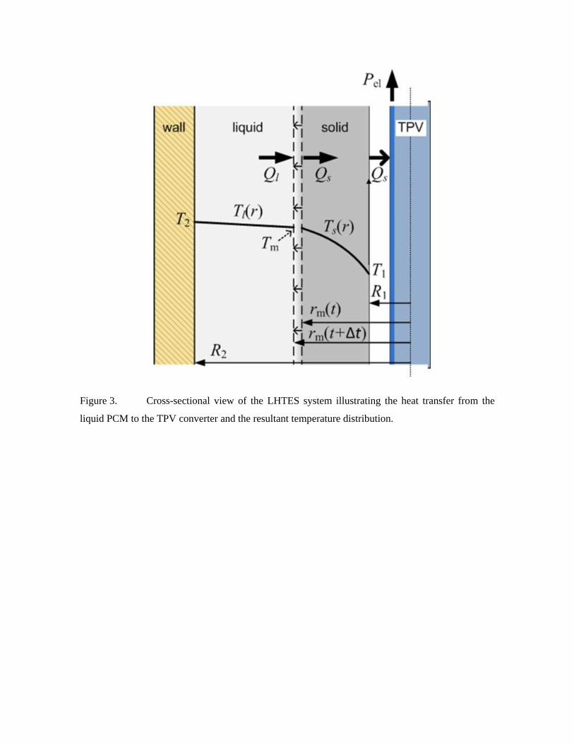
Figure 3. Cross-sectional view of the LHTES system illustrating the heat transfer from the
liquid PCM to the TPV converter and the resultant temperature distribution.

Figure 4. Specific energy and energy density of several energy storage systems (taken from
[28], [29]). Silicon-TES reefers to the system analyzed in this work.

Figure 5. Output power as a function of time during the discharge of an LHTES system
(L=1m, R1=0.2m, R2=0.5m and ideal 0.5eV TPV cells, i.e. ηint = 1 and ρBR=1). This result represents
the full-power discharge mode, i.e. the TPV converter is entirely introduced in the cavity from the
beginning.

Figure 6. Temperature profile in the silicon PCM as a function of time for the LHTES system
corresponding to the result shown in Figure 5 (L=1m, R1=0.2m, R2=0.5m and ideal 0.5eV TPV
cells, i.e. ηint = 1 and ρBR=1).

Figure 7. External photoluminescent efficiency as a function of the BSR reflectivity and the
internal photoluminescent efficiency. State of the art (lattice matched) GaAs solar cells have
demonstrated ηint ~ 0.97. Silicon LEDs have demonstrated ηext ~ 0.01.

Figure 8. Average heat-to-electricity conversion efficiency during the discharge of the
LHTES system as a function of the TPV cell bandgap, the BSR reflectivity and the internal
photoluminescent efficiency. The LHTES system has the following configuration parameters:
L=1m, R1=0.2m, R2=0.5m.

Figure 9. Average output electric power as a function of the TPV cell bandgap, the BSR
reflectivity and the internal photoluminescent efficiency. The LHTES system has the following
configuration parameters: L=1m, R1=0.2m, R2=0.5m. The average electric power density, in kW per
m2 of TPV cell area, is obtained dividing the data of this Figure (in kW) by the total TPV cell area
of m2. For instance, an average output power of 25 kW corresponds to an average
output power density of ~ 2 W/cm2.

Figure 10. Discharge time of the LHTES system as a function of the TPV cell bandgap, the
BSR reflectivity and the internal photoluminescent efficiency. The LHTES system has the
following configuration parameters: L=1m, R1=0.2m, R2=0.5m. (results are almost independent of
ηint).