ultimate strength assessment of steel-welded hemispheres
TRANSCRIPT

RESEARCH ARTICLE
Ultimate Strength Assessment of Steel-Welded Hemispheresunder External Hydrostatic Pressure
Sang-Rai Cho1,2& Teguh Muttaqie3,4 & Seung Hyun Lee5
& Jaewoo Paek6 & Jung Min Sohn3,7
Received: 7 October 2019 /Accepted: 13 May 2020# The Author(s) 2021
AbstractThis paper focusses on steel-welded hemispherical shells subjected to external hydrostatic pressure. The experimental andnumerical investigations were performed to study their failure behaviour. The model was fabricated from mild steel and madethrough press forming and welding. We therefore considered the effect of initial shape imperfection, variation of thickness andresidual stress obtained from the actual structures. Four hemisphere models designed with R/t from 50 to 130 were tested untilfailure. Prior to the test, the actual geometric imperfection and shell thickness were carefully measured. The comparisons ofavailable design codes (PD 5500, ABS, DNV-GL) in calculating the collapse pressure were also highlighted against the availablepublished test data on steel-welded hemispheres. Furthermore, the nonlinear FE simulations were also conducted to substantiatethe ultimate load capacity and plastic deformation of the models that were tested. Parametric dependence of the level ofsphericity, varying thickness and residual welding stresses were also numerically considered in the benchmark studies. Thestructure behaviour from the experiments was used to verify the numerical analysis. In this work, both collapse pressure andfailure mode in the numerical model were consistent with the experimental model.
Keywords Steel-welded hemisphere . Collapse pressure . Experiment . Nonlinear FEA . Ultimate strength formulation
1 Introduction
The pressure hull is the most important structural elementof submarines and submersibles. These structures must bedesigned to meet their ultimate strength requirement with acertain safety margin to confirm their desirable divingdepth. The spherical form most likely can withstand thehighest pressures and widely used in deep manned pressurehulls. The use of titanium spherical hull type was recentlyconsidered the most effective in load-carrying capacity inthe Hadal zone exploration that reaches to depths of6000 m and beyond. These are some success stories inthe development of state-of-the-art manned submersiblevehicles such as Jiaolong operated by China NDSC (Cui2018), Shinkai operated by JAMSTEC, Nautile operatedby IFREMER, and Consul AS37 operated by RussianNavy (Kohnen 2018). This development of deep mannedsubmersibles represents its important contributions to theultimate strength of spherical shells. However, on the otherpoint of view, the spherical form is ineffective for manag-ing the internal space arrangement for more complexequipment and those with higher number of crew com-pared with a cylinder with the same volume space.
Article Highlights• Experimental and numerical investigations on welded segment andcrown hemisphere were performed.
• Parametric dependence of the level of sphericity, varying thickness andresidual welding stresses were also included in the numerical model.
• Accuracy of the predicted design rules was evaluated against thereported test results on the steel-welded model.
• Failure behaviour of the welded test model was investigated.
* Jung Min [email protected]
1 Ulsan Lab, Inc., Ulsan, South Korea2 School of Naval Architecture and Ocean Engineering, University of
Ulsan, Ulsan, South Korea3 Department of Naval Architecture and Marine Systems Engineering,
Pukyong National University, Busan, South Korea4 Agency for the Assessment and Application of Technology, Center
of Technology for Defense and Security Industries – BPPT,Jakarta, Indonesia
5 Hyundai Mipo Dockyard, Ulsan, South Korea6 Hyundai Heavy Industries, Ulsan, South Korea7 Interdisciplinary Program of Marine Convergence Design, Pukyong
National University, Busan, South Korea
https://doi.org/10.1007/s11804-020-00178-8
/ Published online: 15 January 2021
Journal of Marine Science and Application (2020) 19:615–633

Therefore, ring-stiffened cylinders have been adopted forthe main structural form of naval submarines. However, toachieve their optimum design and fulfil the hydrodynamicaspects, those ring-stiffened cylinders are obstructed off bya hemisphere or a torisphere.
The subject of hemispheric shells that can endure the ex-ternal buckling loads has presented scientific and engineeringchallenges for more than 100 years (Blachut 2014). Zoelly(1915) derived the first classical buckling theory on sphericalform using the relationship between the elasticity modulus,the Poisson ratio of the base material, the radius and the thick-ness. The theory was based on the assumption of an idealperfect hemisphere. Thus, the effects of initial shape imper-fection, variation of thickness and residual welding stresseshave not been considered in the prediction.
Approximately 53 years ago, extensive experimental workwas carried out by US Navy at the David Taylor Model Basin(Krenzke and Kiernan 1965; Kiernan and Nishida 1966) andNaval Ship Research and Development Center (Costello andNishida 1967; Costello 1970) to acquire feasible criteria forthe ultimate strength of the fabricated shells. The results showthat the deviation of the sphericity, including the thinning dueto cold forming, and the presence of the residual weldingstress exerted in the fabricated model must be considered toachieve accurate prediction of the ultimate strength. The dis-crepancy between analytical and experimental data for thedeep and shallow spherical shell was also explained byNASA (1969), which gives the recommendation to threatthe design buckling pressure as the lower bound of the exper-imental data.
Galletly et al. (1987) and Galletly and Blachut (1991)then used these evaluations and the reported data as thebasis for the further numerical investigation of imperfectsteel hemispheres. They found that the lower bound of theUS Navy test results can be approximated using polynomi-al imperfection to determine the required imperfection ofthe magnitude-to-shell thickness, δ/t = 0.3 for 33 < R/t < 78model size. However, the constant value of imperfectionmagnitude δ/t will be increased two times for the modelover the range of 78 < R/t < 165. Shao and Frieze (1989a,b) also determine the collapse load of the hemisphereshaving asymmetric initial shapes. The testing was thencontinued by Blachut and Galletly (1993; 1995) usingnear-perfect torisphere and hemisphere to assess the influ-ence of local imperfection. Seven imperfect spun steelhemispheres in the range of R/t = 116 to 784 have also beenexamined. Local and global eigenmode imperfection sen-sitivities were also evaluated through the torispherical, el-lipsoidal, and toroidal shell (Blachut and Jaiswal 1999).Evkin and Lykhachova (2017) recommend estimating thedesign buckling load of spherical shell using the energyperturbation. This design criterion calculated the bucklingenergy which allows to estimate the perturbation
sensitivity and verified through numerical analysis of aspherical shell. An analysis of the imperfection sensitivityof the spherical shell was also conducted by Wagner et al.(2018). They proposed the design procedure that employedthe knockdown factor for the collapse predictions of spher-ical shells. The empirical equation substantiates the initialimperfection that was derived based on the numerical anal-yses. The demand of the spherical shapes in the engineer-ing application has also triggered the other similar shapessuch as torispherical and domes (Blachut et al. 1990,Blachut et al. 1991, Moffat et al. 1992, Blachut 1998) witha variation of height-to-diameter from 0.2 to 1.0, R/t= 60 to100, domes for R/t = 100 (Blachut 2015), bi-segment of anR/t = 94 spherical shell (Chen et al. 2017) and sphericalcaps for R/t = 40 to 125 (Zhang et al. 2018a, b, 2019). Analternative design of the bionic spherical shell, the egg-shaped pressure hull, has also numerically and experimen-tally been studied by Zhang et al. (2017a, b). This researchprovides a new concept of pressure hull design where it isnoted that the egg-shaped pressure hull is less sensitive togeometric imperfection than the conventional sphericalshell.
The main goal of the current paper is to assess thereliability of FE analysis for predicting the collapse pres-sure of the steel-welded hemisphere, thus enabling engi-neers to use that numerical tool with confidence in deter-mining the capacity in the actual structure case. With thatgoal in mind, the present study starts with re-running theultimate strength experiment on the fabricated steel hemi-sphere under external hydrostatic pressure. In addition,this work is part of the continuous research on pressurehull structures, after the study of the ring-stiffened cylin-der (Cho et al. 2018) and the conical shell (Cho et al.2019). Subsequently, the details of the previous publishedidentical tests on the welded hemisphere and the presentfabricated test model on four hemisphere models arebriefly summarized in the following section. The detailsof the present experimental investigation, test procedureand their results are presented in Section 3. Nonlinear FEanalyses considering the initial shape of imperfection,varying thickness and residual welding stress were thenperformed. Before performing the analyses on the presenttest models, the numerical benchmark on the previouspublished tests on the near-perfect and fabricated hemi-sphere was performed in Section 4. The review on thecollapse strength code recommendations from DetNorske Veritas, buckling strength analysis (DNV 1995),PD 5500 (PD 5500 2003), Germanischer Lloyd, navalship technology (DNV-GL 2015), and American Bureauof Shipping, underwater vehicles, systems and hyperbaricfacilities (ABS 2011) are provided in Section 5. The dis-cussion is provided in Section 6, and conclusions are de-scribed in Section 7.
616 Journal of Marine Science and Application
2 Welded Segment and Crown HemisphereTest Model
2.1 Review of Previous Work
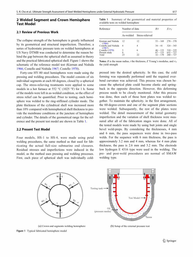
The collapse strength of the hemisphere is greatly influencedby its geometrical and structural imperfection. Therefore, aseries of hydrostatic pressure tests on welded hemispheres atUS Navy DTMB was conducted to determine the reason be-hind the gap between the spherical shell as assumed in theoryand the practical fabricated spherical shell. Figure 1 shows theschematic of the reference model test (Kiernan and Nishida1966; Costello and Nishida 1967; Costello 1970).
Forty-one HY-80 steel hemispheres were made using thepressing and welding procedures. The model consists of sixindividual segments at each 60 degrees, closed by a sphericalcap. The stress-relieving treatments were applied to somemodels in a hot furnace at 552 °C (1025 °F) for 1 h. Someof the models were left in as-welded condition, so the effect ofstress relief can be quantified. Prior to testing, each hemi-sphere was welded to the ring-stiffened cylinder mode. Theplate thickness of the cylindrical shell was increased morethan 10% compared with hemispherical shell thickness to pro-vide the membrane conditions at the juncture of hemisphereand cylinder. The details of the geometrical range for the ref-erence and the present test model are shown in Table 1.
2.2 Present Test Model
Four models, HS-1 to HS-4, were made using petalwelding procedures, the same method as that used for fab-ricating the actual full-size submarine end closures.Residual stresses and imperfections were induced in themodel, as the method uses pressing and welding processes.First, each piece of spherical shell was individually cold-
pressed into the desired sphericity. In this case, the coldforming was repeatedly performed until the required over-bend curvature was achieved. This process was chosen be-cause the spherical plate could become elastic and spring-back in the opposite direction. However, this deformingprocess needs to be closely monitored. After this processwas done, then each of those bent plates was welded to-gether. To maintain the sphericity, in the first arrangement,the 60-degree-crown and one of the segment plate sectionswere welded. Subsequently, the rest of the plates werewelded. The detail measurement of the initial geometryimperfection and the variation of shell thickness were mea-sured after all of the fabrication stages were done. All ofthe tested models were made by using butt joints and singlebevel weld-preps. By considering the thicknesses, 4 mmand 6 mm, the pass sequences were done in two-passwelds. For the sequence with 6 mm thickness, the pass isapproximately 3.2 mm and 4 mm, whereas for 4 mm platethickness, the pass is 2.6 mm and 3.2 mm. The electrodelow hydrogen E 4316 type were used in the welding. Thepre- and post-weld procedures are normal of SMAWwelding type.
Test Model
Testing tank
Oil
(pressure media)
(a) Crown and segments welding hemisphere (b) Setup of the external pressure test
Figure 1 Typical fabricated hemisphere model
Table 1 Summary of the geometrical and material properties ofavailable tests on welded hemisphere
Reference Number of data R/t E/σY
As-welded Stress-relieved
Kiernan and Nishida(1966)
12 12 53 ~ 169 270 ~ 370
Costello and Nishida(1967)
4 4 34 ~ 41 324 ~ 343
Costello (1970) 3 6 46 ~ 133 310 ~ 335Present study 4 - 87 ~ 133 632 ~ 727Total 23 22 32 ~ 170 260 ~ 727
Notes: R is the mean radius, t the thickness, E Young’s modulus, and σYthe yield strength
617S.-R. Cho et al.: Ultimate Strength Assessment of Steel-Welded Hemispheres under External Hydrostatic Pressure

A schematic and photograph of the recent test modelsare shown in Figure 2. Three types of welding type wereinvestigated in this study. Models HS-1 and HS-4 consistof four segment and one crown. Model HS-2 has threesegment and one crown. Finally, a single shell segmentwas used in model HS-3.
A quasi-static tensile test was performed on coupons cutfrom the same sheet metal from which the hemispherical shellwas fabricated. All of the test models were made from SS41mild steel. The detail of the dimensions of the recent test hemi-spheres and the results of the average value from the tensile testare given in Table 2. For all calculations, Young’s modulus, E,and Poisson’s ratio, ν, are fixed at 20 6000 MPa and 0.3, re-spectively. In Figure 3, the engineering stress-strain relation ofSS41material which was adopted in the forthcoming numericalanalysis is shown. The yield strength σY was obtained from0.2% offset and in the ranges of 290–332 MPa, and ultimatetensile strength, σT, is 422–457 MPa.
3 Setup of Experiments
3.1 Preparation Before the Test
Eachmodel was measured for initial imperfections and thicknessvariations. The measurements were conducted on a custom ro-tating table (free to rotate) with a dial gauge attached at the arc-shaped steel rail. The rail is fixed at the location of the primemeridian of the hemisphere. Thus, the relative distance of thewhole direction of the shell can be determined precisely. Forthe thickness measurement, an ultrasonic gauge was used. Thephotograph of the device and the typical model measurement inwhich the model is placed on the turn-table are shown inFigure 4. To support the spatial measurements, the latitude andlongitude gridlines were made. The gridlines were drawn at ev-ery 15° interval. The initial shape imperfections and thicknessmeasurements were taken at the cross-point between the axiallines and the radial direction from the outer surface of the shell.
(a) (b) (e) (f)
(c) (d) (g) (h)
60O
Crown
Shell
segment
Figure 2 Welding line: (a) HS-1 and HS-4, (b) HS-2, (c) HS-3, (d) Side view, photograph before painting; (e) HS-1, (f) HS-2, and before testing; (g) HS-3, (h) HS-4
Table 2 Details of the test model parameters
Model Shell parameter Material
R (mm) t (mm) S (mm) R/t λ σY(MPa) εY σT (MPa) E
HS-1 502.9 5.75 1580 87.5 20.9 290 0.001408 457 206000
HS-2 302.9 5.72 952 53.0 16.3 287 0.001393 448 206000
HS-3 501.9 3.75 1577 133.8 22.5 332 0.001612 393 206000
HS-4 577.9 5.73 1816 100.9 22.2 293 0.001422 422 206000
Notes: S is arc length of the hemisphere (mm), λ non-dim parameter, S=ffiffiffiffiffiRt
p� �E=1000σYð Þ;σY yield strength (MPa), εY yield strain (non-dim), σT
tensile strength (MPa), and E Young’s modulus (MPa)
618 Journal of Marine Science and Application

By utilizing the result from the dial gauge measure-ments, the spatial coordinates of the hemispherical shellcould be modelled, as seen in Figure 5, for the case ofHS-1. To gain a better presentation, the magnitude hasbeen amplified 10 times the original value. The mea-surement procedures were followed what has been pre-sented in Kendrick (1977). A summary of the imperfec-tion measurements is provided in Table 3. It shows thatthe amplitude deviate from the mean radius for about0.90%–1.52% and are inward facing. Since this is asmall-scaled model with fabrication treatment as in theactual structure, it is not surprising that the degree ofinitial imperfection seems greater than what is found inthe full-sized structure. Subsequently, the shell thicknessmeasurements were taken by an ultrasonic gauge at thesame crossing point of the axial and radial lines in themid-bay. This measurement resulted in 156-point thick-ness. The scattering of the shell thickness information ofthe hemisphere shell model HS-3 is illustrated inFigure 6.
3.2 Apparatus and Testing
In performing the test, all the hemisphere models except modelHS-2 were pressurized in the pressure chamber with an innerlength of 2.8 m and a diameter of 1.3m. Themaximum chamberpressure can be up to 80 bars. All of the tests and procedureswere performed in the Ultimate Limit State ANalysis Laboratory(ULSAN Lab), University of Ulsan. Model HS-2, which wasdesigned to have the highest collapse pressure, was tested using asmall-sized chamber with an inner length of 1.8 m inner lengthand an inner diameter of 0.65 m. In that case, the chamber iscapable of being pressurized up to 120 bars. Figure 7 shows theschematic of the installation of models that were tested in thehorizontal-type small and medium size chambers. Since themodel volume is relatively large (approximately 18 to 28% ofthe chamber volume), the pressure drop evidently occurred im-mediately after reaching the ultimate strength due to the collapseof the structure (a loud bang was heard in the chamber). Thatpressure drop phenomenon is different from the actual subseaconditions where the ambient pressure is constant. However, thestudy is focused on obtaining the ultimate strength and the be-haviour under loading. Thus, the pressure drop is neglected.
Initially, before installation into the chamber, the modelwas welded onto the flange. Then, the O-ring was placed intothe groove at the top plane of the flange where special greaseis also applied. Finally, the model together with the openflange was lifted and inserted into the chamber and boltedusing an air-impact wrench. One active line used for measur-ing the ambient pressure is located at the top, while anotheractive line, which is used to supply the compressed water, islocated at the bottom. The test commenced by increasing theinternal pressure up to 2 bars and then depressurising thechamber by opening the release valve. During the test, loadincrements were uniformly divided into three main runs, thefirst and second up to approximately 25% (±1.5–3 bars) andapproximately 80% (3–5 bars) of the predicted collapse pres-sure, and the third was up to the point of collapse with the loadat every 0.5 bar. At every pressure increment, the pressure was
0.00 0.05 0.10 0.15 0.20 0.25 0.30 0.35 0.40 0.45 0.500.0
50.0
100.0
150.0
200.0
250.0
300.0
350.0
400.0
450.0
0.00 0.01 0.02 0.03 0.04100.0
150.0
200.0
250.0
300.0
350.0
0.2 % Offset
(MPa)
(MP
a)
Figure 3 Typical stress-strain curve from the tensile test
(a) Turn table device with the arc-shape rail dial gauge (b) HS-2 sphericity imperfection measurement
Figure 4 Measurement of initial shape imperfection
619S.-R. Cho et al.: Ultimate Strength Assessment of Steel-Welded Hemispheres under External Hydrostatic Pressure

maintained for approximately 0.5 to 1 min to settle the ambi-ent pressure before increasing further. This procedure wasused to model a similar condition where the actual structuregradually submerges in the subsea operation.
The equipment and custom device used during the test aredescribed in Figure 8. The strain gauges were also installed atthe inner shell of the model at various locations. All of thehemisphere models were subjected to external hydrostaticpressure up to their failure. During the experiment, visibledeformation and other data were recorded to map the trendof plastic deformation to the corresponding area in the shell. Inthe final stage, after the collapse pressure was reached, thepressure was released gradually, and the water started to drainfrom the chamber by opening the release valve at the top andbottom of the chamber.
3.3 Test Results
3.3.1 Failure Mode Evaluation
All hemispheres failed suddenly with an audible sound and apressure drop recorded immediately after reaching the col-lapse pressure. Two types of failure mode were observed fromthe four hemispheres tested. First, the failure occurred starting
from the welding line of the spherical cap and then graduallycompressed downward into a local plastic deformation andspread globally. Second, the initial local stress concentrationoccurred below the crown, near the equator. The plastic de-formation started to decelerate along the meridian and termi-nated at the welding line between the spherical crown and theshell. In the area below the crown, the failure stopped afterengaging the end boundary. The experimental collapse pres-sures and the final deformed configuration of the tested hemi-sphere are depicted in Figure 9. Based on the post-collapseevidence, we suspect that the number of welding lines (reddotted line) and the size of the hemisphere influenced thefailure mode.
Model HS-1 test, which was 500-mm nominal radius and90 degree weld shell segment, was loaded to a maximumpressure of 5.49 MPa. Receding slightly inward immediatelyafter the ultimate point, water was continuously injected, andthe pressure continued to drop to 3.0 MPa. The severity of thiscollapse shape occurred at approximately 270 degrees at thespherical cap involving 2/3 of the hemisphere. In the case ofHS-2, a failure mode similar to HS-1 was observed. Thismodel is a 120 degree shell welding line configuration, small-er than HS-1 with a nominal 300-mm radius with the samethickness. The shell moved slightly inward after pressuriza-tion, and a maximum pressure of 9.81 MPa was recorded.However, the model resisted a pressure up to 80% higher thanthe previousmodel. After the collapse, the pressure dropped to5.30 MPa. The centre of the dent was located at the weld lineof the crown.
Specimen HS-3 was loaded to collapse and failed at theside shell. Model HS-3 was designed to have the same sizesphere radius as HS-1, but the shell thickness was nominally3.75 mm. The welding configuration had only a single shellsegment and its cap. The failure was initiated by yielding ofthe area 20 degrees above near boundary at 285 degrees lon-gitude. The collapsing walls had grown, covering the area at
-600 -400 -200 0 200 400 600-600
-400
-200
0
200
400
600
Radius (mm)
Rad
ius
(mm
) Perfect circle
Lat 0 degLat 15 degLat 30 degLat 45 degLat 60 degLat 75 deg
Top view
-600 -400 -200 0 200 400 600
0
200
400
600
-600 -400 -200 0 200 400 600
0
200
400
600
Rad
ius
(mm
)
0o~ 180o
Radius (mm)
Rad
ius
(mm
)
180o~ 360o
Figure 5 Initial shape imperfection magnified 10 times (HS-1 model)
Table 3 Details of the imperfection parameter
Model Max. shell out-of-roundness (δ) tmin tavg(mm)
tmax
δ/R(%)
Rmin Rmax Location(mm)
HS-1 0.90 498.32 503.48 Lat 60o, Long 150o 5.34 5.75 5.92
HS-2 1.52 298.25 305.55 Lat 0o, Long 150o 5.32 5.72 5.95
HS-3 1.14 496.13 505.67 Lat 0o, Long 150o 3.62 3.75 4.10
HS-4 0.78 573.34 580.46 Lat 60o, Long 60o 5.27 5.73 5.94
620 Journal of Marine Science and Application

approximately 45 degrees. The pressure gauge reached a max-imum pressure of 3.10MPa. The last tested model (HS-4) hada configuration similar to HS-1 with a larger diameter.Surprisingly, in this model, the localized plastic deformationfollowed the HS-3 model at the area below the crown. Thecrown of inward deformation abruptly stopped when the col-lapse reached the end boundary and the crown. The computerrecorded that this model failed at a pressure of 4.30 MPa.
3.3.2 Pressure and Strain Evaluation
In this subsection, two typical types of failure were analysed (i.e.crown failure and shell segment failure). The circumferentialstrain configuration on the inner side of the hemisphere modelof HS-1 (crown failure) plotted against the applied pressure isdepicted in Figure 10. A red-filled failure area of eachmodel wasnoticed. In the case of model HS-1, the crown area experienced
compression, where the largest strain was monitored on strain#4. The tension part was located at the opposite of failure region,showed by strain #1, #2 and #5. The maximum tension strainwas found to be about 75% of yield strain. Thus, from the strainmeasurement, the location of the first shell yield was expected tobe the location of the maximum post-collapse deformation. Thislocation was at approximately 207° around the welding line ofthe crown. Once the compressive stress near the welding linereached its yielding stress, the localized plastic deformation pen-etrated downward to the equator.
Before reaching collapse, model HS-3 began to visiblydeform between strain position #3 and #8. The deformationshowing inward stretching behaviour grew towards theboundary and upward to the crown. Figure 11 shows the re-sponse of applied pressure against the strain measurementwith their corresponding location. For side shell segment fail-ure, the opposite dent area is in tension. The maximum tension
Figure 6 Plotting of thickness variation (HS-3 model)
Figure 7 Ultimate strength test setup in the main facility
621S.-R. Cho et al.: Ultimate Strength Assessment of Steel-Welded Hemispheres under External Hydrostatic Pressure

strain recorded in position #4 and #6 was approximately 66%of the yield strain.
4 Numerical Analyses
In the present study, finite element analyses were performedusing a commercial software package Abaqus FEA. The S4Relement, which is a 4-node doubly curved finite-strain elementwith reduced integration and hourglass control, was used fordiscretization of the physical models. Mesh convergence stud-ies were performed to determine the required mesh density.Pessimistically, the material behaviour was assumed to beelastic-perfect plastic, though this is a reasonable assumptionfor ultimate strength considerations (Cho et al. 2018, 2019).The shell element also showed good agreement, and compu-tational time can be saved up in the modelling of weldingsimulation (Shen and Chen 2014). As the solution procedure,a modified Riks method was utilized, which allows both snap-back and snap-through to the post-collapse. Initially, to verifythe load and boundary conditions, numerical models for sym-metrical buckling and for the uppermost of the critical
buckling pressures (eigen buckling pressure), the general so-lution derived by Zoelly (Eq. 1) was used. The results for 50cases of the numerical hemisphere models that varied in the R/t ratio agree perfectly with the solution as presented inFigure 12. Most of the hemisphere models are numericallytested with the load and BCs of the analyses as presented.Numerical benchmarking was conducted to verify thenonlinear numerical procedures and the validity of theresults. Two previous laboratory test models were used as abenchmark. The details of the experiments can be found inKiernan and Nishida (1966) and Blachut et al. (1990).
Pe ¼ 2Effiffiffiffiffiffiffiffiffiffiffiffiffiffiffiffi3 1−v2ð Þp t=Rð Þ2 ð1Þ
4.1 Numerical Benchmark on Near-PerfectHemisphere
In this benchmark, the machined steel domes were utilized.Themodels weremachined on computer-controlled numericallathe. Thus, the models achieved a spherical shape which wasnearly perfect with no initial radial deviations. The variation of
Figure 8 Pre- and post-test procedures of the ultimate strength assessment
622 Journal of Marine Science and Application

the shell thickness of the domes differed by almost 4% fromtheir average thickness. The thickness measurement resultsalong the shell are reported in Table 4. All of the modelshad a diameter of 0.2 m and a thickness between 0.653 and
0.775. The variation in thickness shows that the area aroundthe pole is thicker and becomes thinner approaching the equa-tor. This variation is most likely due to the effect of the ma-chined models that were formed from billet mild steel. The
Figure 9 Post-failure shape evaluation for all tested hemisphere model
0.000 0.001 0.002 0.003 0.0040.0
1.0
2.0
3.0
4.0
5.0
6.0
Strain #1 Strain #5
Strain #2 Strain #6
Strain #3 Strain #7
Strain #4 Strain #8
p(M
Pa)
(-)
Figure 10 Pressure and strain evaluation model HS-1 (crown failure)
623S.-R. Cho et al.: Ultimate Strength Assessment of Steel-Welded Hemispheres under External Hydrostatic Pressure

average properties of yield strength σy and the Young’s mod-ulus Ewere determined to be 303.5 and 207 000MPa, respec-tively. In the numerical analyses, the steel was assumed to beelastic and perfectly plastic. As Figure 13 shows, the failureshape between the numerical and the test results was verified.In Table 5, the accuracy of the prediction reached 95%. Thediscrepancies among the models are influenced by the varia-tion in their shell thickness. The buckling resistance of theshell was controlled by the height of the sphere H/D ratio,where the weakness was shown by the smallest ratio of H/D (Model 1).
4.2 Numerical Benchmark on Previous FabricatedHemisphere
The detrimental effect of the fabricated hemisphere could beassessed by utilizing the initial shape imperfection, the uneventhickness, and the residual welding stress, and fairly goodagreement could be obtained. Yu et al. (2017) simulated thewelding process using their thermodynamic properties andrevealed that the maximum reduction in ultimate strength isless than 3.25%. Tekgoz et al. (2015) modified the stress-strain curves to introduce the residual stress and showed that
the residual stresses reduce the ultimate load remarkably withthicker plates but have less effect when the plate is thin. Toinvestigate this influencing factor, in this case, fabricatedmodels from Kiernan and Nishida were used. Two pairs ofidentical models made from HY-80 steel were used. One wasthe stress-relieved model, and the other was without relievingstress, leaving the welding process as it is. Models 1 and 3 hada diameter of 381 mm, and models 16 and 14 had a diameterof 838.2 mm. In the stress-relieved model, the model wasinserted into the hot furnace for 1 h. Then, the model wasremoved from the furnace and stored at room temperature.By this procedure, the residual welding stress can be dimin-ished. Hence, the buckling resistance was expected to behigher than in the as-welded model. To consider this effect,the weld-line of the hemispherical segment needed to bemodelled.
In the numerical analyses, the welding tensile stress wasequal to the yield strength of the material. These stresses wereestablished along the welding line, whereas the compressivestress which using an assumption of 0.17 of σY (Faulkner1977) was applied at the outside of the weld-lines (acrossthe welding lines). The value of 17% of yield strength is rea-sonable involving other parameters such as the initial shape of
p(M
Pa)
(-)
-0.001 0.000 0.001 0.002 0.0030.0
0.5
1.0
1.5
2.0
2.5
3.0
3.5
Strain #1 Strain #5
Strain #2 Strain #6
Strain #3 Strain #7
Strain #4 Strain #8
Figure 11 Pressure and strain evaluation of model HS-3 (shell segment failure)
0
50
100
150
200
250
300
0 50 100 150 200 250 300
P e(N
um)
Pe (Zoelly Equation)
Parameter Range Qty
R/t 25 - 250
E 207000 MPa50 cases
Boundary conditions
ux=uy=uz=urx=ury=urz=0
External pressure
Figure 12 Load and boundary condition for the linear FEA and validation with Zoelly critical pressure
624 Journal of Marine Science and Application

the imperfection and the variation of the thickness. It wasdetermined later that Grunitz (2004) re-tested the flat weldedsteel in which the effect of initial imperfection and thicknessvariations were negligible. The specimens of HY-80 materialwere examined using a neutron strain diffractometer and de-termined that the compressive strength was 190 MPa, whichwas approximately 30% of the tensile strength at the weld line.
The results of the numerical analyses of these models aregiven in Table 6. An equivalent magnitude of imperfection (δ)from Galletly et al. (1987) was used, assumed to be δ/t = 0.5.Both the experimental and the numerically investigated valuesfor the collapse prediction and the failure modes agreed well.In the same table, the ultimate strength of the stress-relieved isapproximately 2 to 8% higher than the as-welded model. Inthe numerical study, stress-relieved means without residualstress. Overall, the initial imperfection and assumption of thewelding residual stress in the numerical analysis proceduresgive 96% accuracy for those two kinds of test models.
In Figure 14, the deformed shape is given together withthe actual photograph from the test results of the stress-
relieved and as-welded (models 1 and 3, respectively).Close agreement was achieved where two models failedat the same location, the failure shape at the 0°- weldingline. To obtain more specific information, the difference inapplying the residual stress, the initial loading phase, be-fore and post-collapse are presented in Figure 15. For theas-welded model, as the pressure increases, the residualstress is spread over the shell segment and crown intersec-tion as shown in image Figure 15(a). Before reaching theultimate state, regions in addition to the welding line re-ceive higher compressive stress. The crown-segmentwelding intersection can no longer provide support, sothe plastic deformation starts to develop, as shown inFigure 15(b). Finally, the local stress concentration at thecrown-segment welding intersection promotes a shell fail-ure which reduces the structural strength, and the collaps-ing wall starts to decelerate approaching the boundary, asshown in Figure 15(c).
Table 4 Thickness measurement of the near-perfect test models
Meridian numbers
The typical thickness variation on machined model
1 2 3 4 5 6 7 8
0.667 0.667 0.667 0.667 0.667 0.667 0.667 0.667
0.676 0.674 0.676 0.680 0.678 0.675 0.673 0.676
0.680 0.681 0.675 0.673 0.675 0.680 0.680 0.678
0.674 0.674 0.668 0.663 0.671 0.674 0.674 0.676
0.672 0.675 0.674 0.672 0.674 0.677 0.672 0.677
0.672 0.673 0.673 0.674 0.674 0.674 0.672 0.676
0.672 0.673 0.671 0.671 0.671 0.672 0.672 0.670
0.666 0.673 0.671 0.670 0.671 0.672 0.670 0.671
0.670 0.668 0.670 0.672 0.669 0.669 0.670 0.669
0.670 0.672 0.672 0.672 0.673 0.673 0.671 0.673
0.668 0.670 0.668 0.670 0.667 0.670 0.667 0.668
0.668 0.667 0.666 0.666 0.666 0.669 0.666 0.668
0.663 0.665 0.664 0.663 0.664 0.663 0.665 0.669
0.669 0.671 0.669 0.667 0.668 0.669 0.670 0.670
0.667 0.667 0.666 0.667 0.667 0.670 0.664 0.668
0.661 0.663 0.660 0.664 0.657 0.663 0.663 0.662
0.654 0.661 0.654 0.656 0.649 0.656 0.652 0.654
Figure 13 Nonlinear FEAbenchmark results using near-perfect test models
625S.-R. Cho et al.: Ultimate Strength Assessment of Steel-Welded Hemispheres under External Hydrostatic Pressure
4.3 Evaluation on Present Test Model
After the accuracy of the numerical benchmarking was shown,the present test model was analysed. Initially, mesh convergencestudies were performed for all the welded models, namely, HS-1to HS-4. Each mesh was composed of sweep-quad dominatedshells with rough mesh at the welding block. Figure 16 showsthe results of a convergence study where 6 mm× 6 mm meshwas chosen for the appropriate size. The ratio Xm, the eigenbuckling pressure and the upper limit elastic buckling pressurefrom Eq. (1) were used to obtain the converged results.
The measured data of outer surface hemispherical shell wasused in 3-D coordinates and recalled through a commercialCAD software package. Subsequently, the developed shell ge-ometry was imported into Abaqus. In addition, thickness vari-ation for each mapped coordinates was inserted as the actualshell thickness. The residual welding stress assumption that wasassessed in previous benchmark analyses was used. All of thefinite element models were fully clamped, the same as in earlieranalyses. For all numerical models, a uniform pressure incre-ment of 1.0 MPa was applied externally as described inFigure 12. The collapse pressures were determined on the max-imum load proportional factor that is equal to the critical pres-sure of the nonlinear buckling analyses. Table 7 presents thecomparison of the predicted collapse pressure and the failureshape. In all analyses, the failure modes appear to have a plasticdeformation similar to the test results. The modelling of theuncertainty factor of the accuracy, Xm, was taken as the ratioof experimental and predicted collapse pressure. The mean thatwas obtained and the COV show a reliable solution with goodaccuracy, as much as 0.99 and 6.87%. Overall, the qualitative
and quantitative validation from the numerical results showsgood agreement and can be used for the prediction of the ulti-mate strength of the actual fabricated structures.
5 Ultimate Strength Formulation
The following sections present the analytical quantities used forthe pressure hull design codes. The contemporary pressure hulldesign codes such as PD 5500 (PD 5500 2003), GermanischerLloyd (DNV-GL 2015), American Bureau of Shipping (ABS2011) and Det Norske Veritas (DNV 1995) have been chosento provide a thorough substantiation of the ultimate strengthprediction. Most design codes use a conventional deterministicworking stress approach, undertaking an analysis for each modeof failure. A single safety factor or several partial safety factors(PSFs), accounting for uncertainties in the loading, fabricationand strength of the pressure hull, were applied to the character-istic strength to determine the allowable working pressure.
The critical buckling (Pe) formulation of a complete spher-ical shell under external uniform pressure was at first solvedby Zoelly in Eq. (1). This classical theory was the basis of therecent design codes. In this further subsection, several designcodes will be assessed with the available data from previousand present test results.
5.1 Det Norske Veritas
Buckling of an unstiffened spherical shell occurs when thelargest compressive principal membrane stress reaches a crit-ical value, σcr. It may be taken as:
σcr ¼ σY=ffiffiffiffiffiffiffiffiffiffiffiffiffi1þ λ4
p� �
λ ¼ffiffiffiffiffiffiffiffiffiffiffiffiffiffiffiffiffiffiffiffiffiffiffiffiffiffiffiffiffiffiffiffiffiffiσy= 0:606ρEt=Rð Þ
q; ρ ¼ 0:5=
ffiffiffiffiffiffiffiffiffiffiffiffiffiffiffiffiffiffiffi1þ R
100 t
r ð2Þ
where R is the shell radius, t is the thickness, σY is the yieldstrength of the material, λ is the reduced slenderness, and ρ isthe imperfection factor. Hence, the collapse pressure (Pc1) isgiven by:
Pc1 ¼ 2tσcr=R ð3Þ
Table 5 Nonlinear FEA benchmark accuracy using near-perfect testmodels
Collapse pressure(MPa)
Model 4(d) Model 3(c) Model 2(b) Model 1(a)H/D=0.5 H/D=0.4 H/D=0.3 H/D=0.2
PC, Test 3.85 1.53 1.38 1.10
PC, Num 3.75 1.59 1.49 1.21
PC, Test/ PC, Num1.02 0.97 0.92 0.91
94.61 % Accuracy
Table 6 Nonlinear FEAbenchmark accuracy usingfabricated test models
Collapse pressure (MPa) Model 1 O) Model 3 X) Model 16 O) Model 14 X)
R/t=97 δ/t=0.5 R/t=78 δ/t=0.5
PC, Test 10.00 9.30 10.70 10.54
PC, Num 9.86 9.59 11.03 10.11
PC, Test/ PC, Num1.01 0.97 0.97 1.04
96.39 % Accuracy
Notes: O) Stress-relieved model, X) As-welded model
626 Journal of Marine Science and Application

For a complete sphere subjected to uniform external pres-sure, the design pressure defined by PY
PY ¼ 2σY t=R ð4Þ
From the Eq. (2), it shows that value of critical stress, σcr, istaking into account the nonlinearity effect of geometry andmaterial. Here, the corresponding safety factor is determinedby the value of PY/Pc1 or σcr/σY.
5.2 American Bureau of Shipping
In the ABS code, the limit pressure (Pc2) for spherical shells isto be obtained from the following equation:
Pc2 ¼ 0:7391 Py 1þ Py=0:3Pe� �2h i−1
2for Pe=Py
� �> 1
Pc2 ¼ 0:2124 Pe for Pe=Py� �
≤1ð5Þ
where Pe and Py shall be determined as Eqs. (1) and (4),respectively.
In determining the allowable working pressure, the limitpressure, Pc2 shall be multiplied by the safety factor which isto be taken as 0.67.
5.3 PD 5500
In PD 5500, the collapse pressure is determined based on theratio between elastic buckling pressure (Pe) to the yield pres-sure (PY) from the Eqs. (1) and (4). The relation is determinedby the following equation:
1
PC3
� �2
¼ 1
0:3Pe
� �2
þ 1
Py
� �2
ð6Þ
The quadratic form is related to the mean strengthcurve of the collection of the test model. An acceptabledesign pressure is controlled by the safety factor whichfitted to test data. For the case, of mean strength curve(PC3), PD 5500 adopts a guaranteed factor of safety of1.75.
5.4 Germanischer Lloyd
In this design code, the strength prediction is calculatedusing the yield pressure and the elastic buckling load. Thecalculated pressure (Pc4) is typically associated withCollapse Diving Pressure (CDP), where the safety factorwas incorporated through this value. The design orNominal Diving Pressure (NDP) is approximately half ofthe CDP. However, the Test Diving Pressure (TDP)should be proofed during the trial where the value is ap-proximately 60% of the CDP. Interestingly, the predictionof the welded spherical shell can be calculated followingthe fabrication criteria. The first refers to the sphericalends that are not stress-relieved and the other refers totempered-stress-relieved spherical ends.
As-welded hemispherical model
for x≤0:47; Pc4 ¼ Pe1
for 0:47 < x≤3:18; Pc4 ¼ Py 0:38þ 0:195Pe1
Py
� �
for x > 3:18; Pc4 ¼ Py
ð7Þ
For stress relieved
for x≤0:595; Pc4 ¼ Pe1
for 0:595 < x≤2:7; Pc4 ¼ Py 0:475þ 0:195Pe1
Py
� �
for x > 2:7; Pc4 ¼ Py
ð8Þ
where x equal to Pe1/PY, Pe1 is the modified version of Zoelly[1] which expressed as
Pe1 ¼ 1:4 Effiffiffiffiffiffiffiffiffiffiffiffiffiffiffiffi3 1−v2ð Þp t
R
� �2
ð9Þ
5.5 Strength Formulation Based on the DerivedKnockdown Factor
It is mentioned in the beginning that the gap betweentheoretical and experimental can be fitted. For this pur-pose, the analytical buckling formula from Zoelly (Eq.(1)) is defined as the basis. NASA (1969) substantiatedthe test data and derived the knockdown factor whichsuited for the shallow and deep spherical shell. Evkin
(a) Stress relieved hemisphere (Model No. 1)
(b) As-welded hemisphere (Model No. 3)
Figure 14 Failure mode validation for the numerical analyses usingfabricated model
627S.-R. Cho et al.: Ultimate Strength Assessment of Steel-Welded Hemispheres under External Hydrostatic Pressure

and Lykhachova (2017) and Wagner et al. (2018) laterimproved the design criterion by taking into account theperturbation effect and expanded the factor for differentshell geometries, respectively. The predictions are as fol-lows:
λ ¼ 1:414 12 1−ν2� � 1=4
: R=tð Þ1=2; shape parameter for hemisphere ð10Þ
PNASA ¼ Pe: 0:14þ 3:2=λ2
� �; for λ > 2 ð11Þ
PEvkin ¼ Pe:0:693= 1−νð Þ1=5λ2=5; for λ≥5 ð12Þ
PWagner ¼ Pe: 5:172 λ−1:464 þ 0:1296
� �; for λ≥5:5 ð13Þ0 100000 200000 300000 400000 500000
0.98
0.99
1.00
1.01
1.01
1.02
1.03
1.04
1.05
Xm
Number of element
Converged solution
(Mesh size 6x6 mm,
solve time 2 hours)
HS-1 3x3
HS-2 4x4
HS-3 6x6
HS-4 10x10
15x15
30x30
Figure 16 Mesh strategies for present test model
Model No. 16 Model No. 14
(a) Initial state of the load
(b) Before reaching the ultimate state
(c) After reaching the ultimate state
Figure 15 Failure mode of thestress relieved (no. 16) and as-welded model (no.14)
628 Journal of Marine Science and Application

Table 7 Deformed shape configurations and calculated collapse prediction
Model name Failure area Experiment results Numerical results
HS-1 Crown
= 5.49 MPa = 5.52 MPa
HS-2 Crown
= 9.81 MPa = 9.25MPa
HS-3 Shell segment
= 3.10 MPa = 3.04 MPa
HS-4 Shell segment
= 4.30 MPa = 4.68 MPa
Notes: Xm=Pc,Exp / Pc.Num ; Mean =1.00, std.Dev=0.06, COV=5.97%
629S.-R. Cho et al.: Ultimate Strength Assessment of Steel-Welded Hemispheres under External Hydrostatic Pressure
It should be noted that the solution of this buckling pressureis based on the shell parameter and empirical knockdownfactor, where it was limited to certain population data.However, this formula will be also applied to the previousand recent tested data and discussed in further section.
6 Discussion
In Figure 17, the results for prediction above design code aresummarized. The prediction was empirically fitted to the ex-perimental data. The biases and coefficient of variation de-pend on the simplified curve fit of the predicted collapse
pressure against the actual pressure. For instance, PD 5500uses the mean curve instead of the lower bound from ABS.As presented in Table 8, the lower bound and mean curveresult in the average of 1.16 and 1.03 from computed designcodes ABS and PD5500, respectively. In case for the GLdesign equation, two criteria for the fabrication model arepresented. The differentiation between welded and stress reliefseems to overestimate the prediction by 4% for the stress-relieved model and 19% for the as-welded model. As evi-denced by the table, the buckling prediction using the estima-tion from Eqs. (11–13) seems unsatisfied against the hemi-sphere test data where the COV are more than 30%. Thesescatters are mainly influenced by the knockdown factor whichare most of the knockdown factor in this case were formed bythe spherical type.
The detailed comparison of predicted collapse amongthe nonlinear FE analysis results, design code and the pres-ent four test models is tabulated in Table 9. Among thedesign code formulae, the results of the ABS rules weredetermined as a lower bound prediction. In contrast, theoverestimated results from DNV-GL and GL elucidatedthe upper-bound prediction; the results showed that theresults from PD 5500 are closer to the mean value.Evidently, the numerical investigation not only predictedthe failure shape, but the collapse prediction also appearedcloser to unity. However, the variation approaches 5.27%,attributed to the residual welding stress needing to be ac-curately assessed. Overall, the nonlinear FEA resultsyielded reasonable predictions.
In numerous practical applications of the submarinepressure hull, the hemisphere was constructed mainly of
0 1 2 3 4 5 6 7 8 9 10 11 12 13 14 150.0
0.2
0.4
0.6
0.8
1.0
1.2
HS-2HS-1
HS-4
P / P
PC /
Py
e y
Previous test (as-welded) *) PD5500
Previous test (stress relieved) *) DNVPresent test (as-welded) ABS
GL (as-welded) GL (stress-relieved)
HS-3
Figure 17 Plot of design equation prediction curve among the test data: *)
as-welded and stress-relieved fabricated hemisphere test data obtainedfrom (Kiernan and Nishida 1966; Costello and Nishida 1967; Costello1970)
Table 8 Comparison of design equation against previous test data
Number of tested data DNV-GL(Eqs. 7, 8)
DNV(Eq. 3)
ABS(Eq. 5)
PD 5500(Eq. 6)
PNASA(Eq. 11)
PEvkin(Eq. 12)
PWagner
(Eq. 13)Accuracy (mean/COV)
23 as-fabricated 0.81/16% 0.90/9% 1.30/10% 1.00/10% 1.47/31% 1.02/35% 1.18/36%22 stress-relieved 0.96/14% – – –
Table 9 Comparison of the test and prediction results
Model R/t λ Pc. Exp Pc. Num Pe Py Experimental / Prediction
(MPa) Num DNV ABS PD 5500 GL
HS-1 87.46 20.94 5.49 5.52 32.59 6.61 0.99 0.95 1.36 1.00 0.83
HS-2 52.95 16.30 9.81 9.25 88.89 10.92 1.06 0.94 1.31 0.97 0.90
HS-3 133.84 22.54 3.10 3.04 13.91 4.96 1.02 0.92 1.31 0.97 0.83
HS-4 100.86 22.17 4.30 4.68 24.51 5.81 0.92 0.89 1.28 0.94 0.84
Mean 1.00 0.93 1.31 0.97 0.85
COV (%) 5.97 2.77 2.51 2.51 3.87
630 Journal of Marine Science and Application

pre-formed shell segments. Currently, the application ofhot forming to pre-form the shell segments is improving,and the initial shapes of imperfections are becomingsmaller. Eventually, the detrimental effect of the stresslocalized from welding is suspected to highly influencethe collapse strength. In Figure 18, a parametric depen-dence of initial imperfection and residual stress on theultimate strength were investigated numerically. The re-sidual stresses show the stresses induced at the shellwelding junction, whereas the initial imperfection is thecombination of out-of-roundness and shell thickness var-iation. The assumed perfect model must have the maxi-mum collapse pressure, i.e. when there is no nonlineareffect induced in the model. The ideal perfectly modelledcollapse pressure is approximately 33% higher than thetest result. The residual stress shows reduction in therange of 6 to 15% from the ideal, where the combinedinitial imperfection and uneven thickness reduce the col-lapse strength as much as 18%.
7 Conclusions
In this paper, a detailed ultimate strength assessment of thesteel-welded hemispherical shell has been carried out.Experimental studies on four fabricated shell segments and aspherical crown have been carried out as the benchmark tosubstantiate the numerical investigation and design formulaassessments. The experimental collapse pressures rangedfrom 3.10 to 9.81 MPa. The most notable points resultingfrom this study are summarized as follows:
1) From the present test data and remarkable previous ex-periments, two typical failure modes of the test
hemispheres were observed. Two hemisphere models(HS-1 and HS-2) failed at the crown area, while the othertwo (models HS-3 and HS-4) collapsed at the shell-segment side. For the machinedmodel (near perfect hemi-sphere), the failure occurred only at the crown. This dif-ferentiation was revealed by the effect of imperfectionand the residual stress from the fabricated model.
2) In the numerical predictions, the nonlinear FEA wasshown to agree well with the experimental results.The predicted failure modes exhibited the same be-haviour that was obtained in the experimental re-sults. The predicted collapse pressures varied from3.04 to 9.25 MPa, where the COV (coefficient ofvariation) was 6%. From this accurate correlation ofthe numerical and the experimental results, an as-sessment of the ultimate strength of the actual struc-ture of the submarine pressure hull can be confi-dently evaluated.
3) Overall, the prediction of four test hemispheres ob-tained by the design code (DNV, ABS, PD5500, GL)was in agreement with the corresponding test resultswith an accuracy of 97%. From the previous collect-ed published test data of 45 models, the accuracywas approximately 85%. The empirical knockdownfactor which derived from spherical shell shows in-consistencies when being asses to hemisphere. Theimprovement of the design formula considering thereduction factor to account for the effect of the re-sidual welding stress and stress-relieving treatmentwould need to be reevaluated. The detailed investi-gation of the quantity and shape of the weld lines ofthe identical size model to the buckling behaviour ofthe fabricated steel hemisphere is also worthy of fur-ther study.
0.000 0.005 0.010 0.015 0.0200.0
0.1
0.2
0.3
0.4
0.5
0.6
0.7
0.8
0.9
1.0
Ideal perfectly hemisphereResidual stress onlyInitial imperfection onlyWelded model (HS-1)
PC/PY
w0/R (Axial displacement)
PC.TEST
= 5.49 MPa
15 16 17 18 19 20 21 22 23 24 252.0
4.0
6.0
8.0
10.0
12.0
HS- 4
HS- 3
HS- 2
Exp.Perfect modelInitial imperfection onlyRes. stress onlyRes. stress + initial imperfection
Non-dim. parameter,
Pres
sure
(MPa
)
HS-1
Y
ERtS
σ1000
(a) Typical pressure-deflection curves for the hemisphere test
model (model HS-1)
(b) Reduction on the ultimate strength
Figure 18 Imperfection effect of the steel welded hemisphere.
631S.-R. Cho et al.: Ultimate Strength Assessment of Steel-Welded Hemispheres under External Hydrostatic Pressure

Acknowledgements The corresponding author would like to acknowl-edge the Research Grant of Pukyong National University (2019).
Open Access This article is licensed under a Creative CommonsAttribution 4.0 International License, which permits use, sharing, adap-tation, distribution and reproduction in any medium or format, as long asyou give appropriate credit to the original author(s) and the source, pro-vide a link to the Creative Commons licence, and indicate if changes weremade. The images or other third party material in this article are includedin the article's Creative Commons licence, unless indicated otherwise in acredit line to the material. If material is not included in the article'sCreative Commons licence and your intended use is not permitted bystatutory regulation or exceeds the permitted use, you will need to obtainpermission directly from the copyright holder. To view a copy of thislicence, visit http://creativecommons.org/licenses/by/4.0/.
References
ABS, American Bureau of Shipping (2011) Rules for building andclassing underwater vehicles, systems and hyperbaric facilities.American Bureau of Shipping, USA
Błachut J (1998) Buckling of sharp knuckle torispheres under externalpressure. Thin-Walled Struct 30:55–77. https://doi.org/10.1016/S0263-8231(97)00032-3
Błachut J (2014) Experimental perspective on the buckling of pressurevessel components. Appl Mech Rev 66:30–33. https://doi.org/10.1115/1.4026067
Blachut J (2015) Locally flattened or dented domes under external pres-sure. Thin-Walled Struct 97:44–52. https://doi.org/10.1016/j.tws.2015.08.022
Błachut J, Galletly GD (1993) Influence of local imperfections on thecollapse strength of domed end closures. Proc Inst Mech Eng PartC J Mech Eng Sci 207:197–207. https://doi.org/10.1243/PIME_PROC_1993_207_117_02
Błachut J, Galletly GD (1995) Buckling strength of imperfect steel hemi-spheres. Thin-Walled Struct 23:1–20. https://doi.org/10.1016/0263-8231(95)00001-T
Blachut J, Galletly GD, Moffat DG (1991) An experimental and numer-ical study into the collapse strength of steel domes, in ‘buckling ofshell structures, on land, in the sea and in the air, (ed.) J.F. Jullien.Elsevier Applied Science Publishers. pp 344-358 (ISBN 1-85166-716-4)
Blachut J, Galletly GD, Moreton DN (1990) Buckling of near-perfectsteel torispherical and hemispherical shells subjected to externalpressure. AIAA 28:1971–1975. https://doi.org/10.2514/3.10506
Błachut J, Jaiswal OR (1999) On the choice of initial geometric imper-fections in externally pressurized shells. J Press Vessel TechnolTrans ASME 121:71–76. https://doi.org/10.1115/1.2883670
Chen Y, Zhang J, TangW, CuiW, ZhangM,Wang F (2017) Buckling ofbi-segment spherical shells under hydrostatic external pressure.Thin-Walled Struct 120:1–8. https://doi.org/10.1016/j.tws.2017.08.017
Cho S-R, Muttaqie T, Do QT, Kim SH, Kim SM, Han DH (2018)Experimental investigations on the failure modes of ring-stiffenedcylinders under external hydrostatic pressure. Int J Nav ArchitOcean Eng 10:711–729. https://doi.org/10.1016/j.ijnaoe.2017.12.002
Cho S-R, Muttaqie T, Do QT, Park SH, Kim SM, So HY, Sohn JM(2019) Experimental study on ultimate strength of steel-weldedring-stiffened conical shell under external hydrostatic pressure.
Mar Struct 67:102634. https://doi.org/10.1016/j.marstruc.2019.102634
Costello MG (1970) The effect of residual stresses on the bucklingstrength of fabricated HY-80 steel hemispherical shell. Naval shipResearch and Development Center. Report 340. USA
Costello MG, Nishida K (1967) The inelastic buckling strength of fabri-cated HY 80 Steel hemispherical shell. US Naval Ship Research andDevelopment Center. Report 230. USA
Cui W (2018) An overview of submersible research and development inChina. J Mar Sci Appl 17:459–470. https://doi.org/10.1007/s11804-018-00062-6
DNV, Veritas DN (1995) Buckling strength analysis. Det Norske VeritasClassification AS, Norway
DNV-GL, Det Norske Veritas - Germanischer Lloyd (2015) Rules forclassification naval vessels, part 4 sub-surface ships chapter 1 sub-marines. DNV GL AS. Norway
Evkin AY, Lykhachova OV (2017) Energy barrier as a criterion for sta-bility estimation of spherical shell under uniform external pressure.Int J Solids Struct 118–119:1339–1351. https://doi.org/10.1016/j.ijsolstr.2017.04.026
Faulkner D (1977) Effects of residual stresses on the ductile strength ofplane welded grillages and of ring stiffened cylinders. J Strain AnalEng Des 12:130–139. https://doi.org/10.1243/03093247V122130
Galletly GD, Blachut J (1991) Buckling design of imperfect weldedhemispherical shells subjected to external pressure. J Mech EngSci 205:175–188. https://doi.org/10.1243/PIME_PROC_1991_205_108_02
Galletly GD, Blachut J, Kruzelecki J (1987) Plastic buckling of imperfecthemispherical shells subjected to external pressure. J Mech Eng Sci201:153–170. https://doi.org/10.1243/PIME_PROC_1987_201_103_02
Grünitz L (2004) Buckling strength of welded HY-80 spherical shells: adirect approach. Ph. D thesis. Arbeitsbereiche Schiffbau derTechnischen Universität Hamburg, Germany
Kendrick SB (1977) Shape imperfections in cylinders and spheres: theirimportance in design and methods of measurement. J Strain Anal12:117–122
Kiernan TJ, Nishida K (1966) The buckling strength of fabricated HY-80spherical shells. David Taylor Model Basin. Report 172. USA
Krenzke MA, Kiernan TJ (1965) The effect of initial imperfection on thecollapse strength of deep spherical shells. David Taylor ModelBasin. Report 175. USA
Kohnen W (2018) MTS manned underwater vehicles 2017-2018 globalindustry overview. Mar Technol Soc J 52:125–151
Moffat DG, Blachut J, Galletly GD (1992) Collapse of externallypressurised petal-welded torispheres and hemispherical end clo-sures, Proc.- of seventh Intl Conf. On pressure vessel technology –ICPVT7. VdTUV. Dusseldorf. Germany 1992:119–137
NASA (1969) Buckling of thin-walled doubly-curved shells. NASAspace vehicle design criteria (structure). NASA SP-8032. USA
PD 5500 (2003) Specification for unfired fusion welded pressure vessels.British Standard Institution. UK
ShaoWJ, Frieze PA (1989a) Static and dynamic numerical analysis stud-ies of hemispheres and spherical caps. Part I: background and theo-ry. Thin-Walled Struct 8:99–118. https://doi.org/10.1016/0263-8231(89)90038-4
ShaoWJ, Frieze PA (1989b) Static and dynamic numerical analysis stud-ies of hemispheres and spherical caps. Part II: results and strengthpredictions. Thin-Walled Struct 8:99–118. https://doi.org/10.1016/0263-8231(89)90038-4
Shen J, Chen Z (2014) Welding simulation of fillet-welded joint usingshell elements with section integration. J Mater Process Technol214:2529–2536. https://doi.org/10.1016/j.jmatprotec.2014.04.034
632 Journal of Marine Science and Application

Tekgoz M, Garbatov Y, Guedes Soares C (2015) Ultimate strength as-sessment of welded stiffened plates. Eng Struct 84(2015):325–339.https://doi.org/10.1016/j.engstruct.2014.12.001
Wagner HNR, Hühne C, Niemann S (2018) Robust knockdown factorsfor the design of spherical shells under external pressure:Development and validation. Int J Mech Sci 141:58–77. https://doi.org/10.1016/j.ijmecsci.2018.03.029
Zhang J, Zhu B,Wang F, TangW,WangW, ZhangM (2017a) Bucklingof prolate egg-shaped domes under hydrostatic external pressure.Thin-Walled Struct 119:296–303. https://doi.org/10.1016/j.tws.2017.06.022
Zhang M, Hua Z, Tang W, Wang F, Wang S (2017b) Buckling of bi-segment spherical shells under hydrostatic external pressure. Thin-Walled Struct 120:1–8. https://doi.org/10.1016/j.tws.2017.08.017
Zhang J, Zhang M, Cui W, Tang W, Wang F, Pan B (2018a) Elastic-plastic buckling of deep sea spherical pressure hulls. Mar Struct 57:38–51. https://doi.org/10.1016/j.marstruc.2017.09.007
Zhang J, Hua Z, Tang W, Wang F, Wang S (2018b) Buckling of exter-nally pressurised egg-shaped shells with variable and constant wallthicknesses. Thin-Walled Struct 132:111–119. https://doi.org/10.1016/j.tws.2018.08.013
Zhang J,Wang Y, TangW, ZhuY, Zhao X (2019) Buckling of externallypressurised spherical caps with wall-thickness reduction. Thin-Walled Struct 136:129–137. https://doi.org/10.1016/j.tws.2018.12.005
Zoelly R (1915) Uber ein Knickungsproblem an der Kugelschale. Ph.DThesis. ETH Zurich. https://doi.org/10.3929/ethz-a-000091951
633S.-R. Cho et al.: Ultimate Strength Assessment of Steel-Welded Hemispheres under External Hydrostatic Pressure