ultimate performance limits and mission capabilities...
TRANSCRIPT

ULTIMATE PERFORMANCE LIMITS AND MISSION CAPABILITIESOF ADVANCED ION THRUSTERS
88-084A. R. Martin, A. Bond and R. A. Bond
Culham Laboratory, Abingdon, Oxon, OX14 3DB, England
Abstract 2. PREVIOUS STUDIES OF ADVANCED MISSIONS
Previous work has reviewed advanced ion thruster The review of previous work in this sectionsystems designed for application to orbit raising is not intended to provide a comprehensive coverageand on-orbit control of large space structures, of past efforts. Rather, it is concerned with someScaling laws were derived which allowed the extra- recent studies of ambitious, long-range missionspolation of thrusters to larger systems and future that used nuclear electric propulsion (NEP) toperformance levels to be carried out. The mission achieve high velocities, and hence relatively shortcapabilities of such advanced thruster systems has trip times over considerable distances.been considered. Their use in cis-Lunar space,near-Solar space and the outer regions of the Solar There is a long history of discussion of theSystem was examined, use of ion thrusters powered by atomic fission for
long range missions 3 ' , but it is only relativelyThe present paper examines the ultimate performance recently that the first estimates of mass, specificlimits and mission capabilities of a nuclear mass, specific power, etc. have been made for sys-powered, advanced ion thruster propulsion system. tems based upon extrapolation of existing techno-This involves consideration of the ultimate ion logy. Consideration of these, together with thethruster capability and performance level, together system described later in the present paper, willwith power supply output level and specific mass indicate the range of system options being studiedvalues to be expected for such systems, at present.
In deriving the system characteristics, realistic 2.1 JPL Interstellar Precursor Missionextrapolations of current technology have beenassumed. The JPL Interstellar Precursor Mission
discussed by Jaffe et al5,' was for a spacecraftwith a heliocentric hyperbolic escape velocity of50-100 km/sec which could travel 400-1,000 AU fromthe Sun in 20-50 years.
1. INTRODUCTIONA fission NEP system was selected as the
In previous work advanced ion thruster baseline propulsion system, with either a one or twoconcepts in general' and the applicability of advan- stage NEP. If two stages are chosen the first takesced thrusters to missions beyond Earth orbit
2 have the form of a NEP booster stage and the second isbeen considered. the spacecraft itself. A long burn time, of 5-10
years, is required to attain the desired velocity,In the first paper I a review and updating of based upon the assumption of a 500 kWe single stage
advanced ion thruster concepts were carried out and NEP. The corresponding burn-out distance may be as
scaling laws were derived for use in extrapolation great as 200 AU or more, well outside the boundaryto larger systems. Possible future performance of the Solar System.
levels, in terms of beam current and voltage, thrustand power requirements were indicated. It was seen It was estimated that the dry (i.e. without
that, in principle, single thruster units with a propellant) power and propulsion system specificspecific impulse of 20,000 seconds, a thrust of 30 mass would be approximately 0.017 kg/W, for anewtons and an input of a few megawatts were concep- 500 k We system with a 20% conversion efficiencytually feasible. using ion thrusters. The performance of such a NEP
system for Solar Escape is shown in Figure 1 for theThe second paper 2 considered the mission case of an exhaust velocity of 10' m/sec (specific
capabilities of such advanced thrusters to the Solar impulse of 10,000 sees). Here it is seen that anSystem, considering their use in cis-Lunar space, excess velocity of 100 km/sec can be achieved by thenear-Solar space and operations in the outer region chosen system with a net spacecraft mass (excludingof the Solar System. Three areas of power produc- power and propulsion systems) of some 1200 kg.tion were investigated and compared. These weresolar photovoltaic power production, the transmis- The burn-out distance is 65 AU, achievedsion of laser beams or microwaves to a remote eight years from launch i.e. approximately 70,000vehicle from a power generating facility, and on- hours reactor full power operating time. To accom-board nuclear power supplies. One general cone- modate reduced power operation for spacecraft powerlusion of the comparative analysis was that for and attitude control, the reactor end-of-life burn-distances greater than about three astronomical up was taken to be the equivalent of 200,000 hoursunits (AU) nuclear electric power supplies were the of full power. This would be sufficient to continuebest option, as long as their specific mass (kilo- to a 50 year mission duration at one third power.grams per watt of electrical output power) was low.Such specific mass values had to be lower than pre- The nuclear-th rmionic power system proposedsent day values of 0.01 kg/W, which implied multi- is shown in Figure 2 . The system uses heat pipesmegawatt systems for nuclear power supplies. (about 100) to transfer heat generated by the reac-
tor to thermionic converters (six per heat pipe).The present paper takes the study a stage After conversion of thermal to electrical energy the
further, in that it is concerned with the long-range remaining heat is carried to the primary radiatoruse of advanced ion thrusters, and their capabi- for dissipation.lities for outer Solar System exploration, or foruse outside the Solar System in interstellar space. Spacecraft mass estimates were based uponThe ultimate performance limits and mission capabi- the criteria that: (a) the dry NEP system should belities are also discussed. 30-35% of spacecraft mass, (b) propellant expen-
diture should be 40-60 of spacecraft mass. This
490
gave the preliminary, non-optimised estimates of tions and scaling relationships exist.Table 1 for the selected system, based upon aninitial mass in low Earth orbit equivalent to the The system chosen was that of a nuclearmaximum payload of the Space Shuttle (32 tonnes). A fission reactor energy source and electric thrus-conceptual configuration of the spacecraft is shown ters. On the grounds that the propulsion systemin Figure 3. exhaust velocity should be of the same order as the
mission velocity, a specific impulse of several2.2 Thousand Astronomical Unit Mission hundred thousand seconds is implied, for a terminal
velocity of 0.02 light speed (6,000 km/sec). IonThe Thousand Astronomical Unit (TAU) exp- engines, with beam voltages in the multi-megavolt
lorer spacecraft was a later _roposal for an inter- range driven by Cockcroft-Walton generators, canstellar precursor mission ' . The primary TAU fulfil this requirement in principle. Some para-mission constraint is to enable a spacecraft with a meters of the system are listed in Table 3.net mass of five tonne to reach 1,000 AU within 50years. In order to accomplish this an NEP system, The reactor assumed for the vehicle was acomprising a 1 MWe power supply and xenon-progelled rotating bed type, based on work by Powell et a112 .ion thrusters, is employed (earlier studies used The 1 GW (1,000 MW) electrical power, derived from amercury systems). The maximum thrust duration of 2.5 GW thermal system with an energy conversionthe propulsion system is assumed to be 10 years, efficiency of 405, was fuelled with U2 ' using fuelthus setting limits on the life at full power for concentration levels approaching 100%. The spent
the system. U2" fuel pellets were assumed to be transferredfrom the reactor, vapourised and fed into the
A typical TAU departure trajectory is shown propulsion system as additional propellant. Fromin Figure 4(a) (viewed from the ecliptic north pole) scaling equations given by Aston , the mass of theand heliocentric distance as a function of time is reactor was assumed to be 9.2 tonne, with a fuelshown in Figure 4(b). The dashed curve here illus- mass of 69 tonne. This gives an overall electricaltrates the effect of a Jupiter swingby. This can specific mass of 7.82 x 10-s kg/W (a figure that isreduce the overall thrust time by about eight months considerably in advance of currently achievableor with the same thrust period can increase the values).final Solar System escape velocity and reduce thetotal trip time to 1,000 AU by 10 years. A mass allocation of five tonnes was provi-
ded for the science, communications and command andThe key technology challenge on the propul- control systems. The initial vehicle mass was some
sion system was thought to be thruster lifetime, set 527 tonnes, and the burn-out terminal velocity wasby the erosion of the extraction grid assembly. 3,660 km/sec. Such a system could realise missionsEach engine is expected to operate for about two of the capability indicated in Figure 6. A distanceyears (18,000 hours). Two thrusters operate at the of 1,000 AU is reached after some 15 years, whilesame time and so, with 20% thruster redundancy, a the vehicle is still under power. The nearest star,total of 12 thrusters are needed. Some parameters Proxima Certauri at a distance of 4.3 light yearsof the baseline propulsion system are shown in Table (272,000 AU), it reached after a 390 years trip2, based upon the data given in Ref. 8 using mercury time.as propellant. Revised data for the use of xenonare given in Ref. 9, but the numbers do not appear None of the parameters listed in Table 3 hasto be entirely self-consistent. a specified performance which has not been attained
in separate tests of other types of systems forThe spacecraft in its thrusting configura- terrestrial applications. However, combining these
tion is shown in Figure 5(a), with the propulsion separate technologies represents an engineeringmodule shown in more detail in Figure 5(b). The challenge of a significant nature.payload module consists of two separate spacecraftand a cruise bus for control of the flight system 2.4 Multi-megawatt NEP Systemsand communications with Earth during the propulsionphase. After the thrust phase the two spacecraft Sercel and Krauthamer have carried out aare jettisoned from the main bus. conceptual design study of a system capable of being
scaled over a range of electrical ower levels fromReactor technology for TAU was based on 20 MW to several hundred megawatts.
considerable advances beyond the SP-100 space powerreactor currently under development. Revision of Details were given of a 200 MW system, usingearlier work (reported in Ref. 8 and reflected in ion thrusters for propulsion. A total of 50 thrus-Table 2) suggested that assumed power system speci- ters were installed, with 41 in operation at any one
fic masses were too low. Nock noted that the cur- time to produce 1,700 newton of thrust. Each thrus-rent (1987) requirement was a specific mass of ter had an input power of 4.9 MW at a beam current0.0125 kg/W, corresponding to a power system mass of of 100 amps and an efficiency of 85%. The system12.5 tonnes for a 1 MW system. Possible changes to exhaust velocity was 200 km/s. Table 4 gives theSP-100 designs to achieve this included improvements mass breakdown for this concept with a 100 tonnein thermoelectric materials to increase power con- payload.version efficiency from 5% to 8%, elimination ofsecondary heat transport loops, optimisation of The reactor system was based upon a lithium-radiators and improved reactor designs for high cooled pellet reactor driving a Rankine cycle dyna-temperature operation. The full power lifetime mic conversion system. The pellets in the reactorrequirement of 10 years is also an increase over the core are contained in a cylindrical volume withseven year design goal for SP-100 . baffles that allow coolant and pellets to circulate
through the core in a controlled manner. As the2.3 JPL Starprobe pellets are circulated, some fraction of the old
pellets is removed and replaced with new pelletsThe JPL Starprobe study1 0 ' 1 1 was directed from a sub-critical storage reserve. Some advan-
towards defining an interstellar propulsion system tages claimed for the pellet reactor concept werewhich could support a flyby mission to one of the compactness, high fuel burn-up and low mass. Theseveral nearby stars. A major guideline in the circulating fuel capability would allow for effec-analysis was that the operating principles of the tive criticality control, safety and mass savings.propulsion system should be based upon familiartechnologies for which reliable performance projec- The performance potential of such a system
491

was evaluated in general terms 1 3. A round trip level thrusters. However, Aston
10 ,11 has sized such
mission to Jupiter could be completed in 2-3 years, units in a more comprehensive manner. He distin-while a round trip to the edge of te ote Solar System guishes between the low power beam current genera-(Neptune or Pluto) would last 7-8 years. For a ting element (ion source, pre-accelerator system andreactor lifetime of 10 years, the minimum trip time supporting power conditioner) and the high powerto Alpha Centauri would be about 2,500 years, for a accelerator section and accompanying power condi-single stage vehicle. tioning system. The heaviest component was the
Crockcroft-Walton accelerator, but this is not usedin the present, modest voltage design of thruster.
3. SPECIFICATION OF A BASELINE Deleting this item then results in a specific massPROPULSION SYSTEM of 0.00035 kg/W. Therefore, the mass of each thrus-
ter is just over one tonne.3.1 Introductory Remarks
This lower specific mass is supported byThis section presents the specification of a consideration of megawatt level accelerators deve-
baseline propulsion system for a vehicle powered by loped for neutral injection heating of fusionadvanced ion thrusters. The thruster characteris- plasmas
1 . One such unit, designed for the Jointtics are derived from the work in Ref. 1, and are European Torus (JET) experiment, operates at 80 kVonly discussed briefly. The power supply charac- beam voltage and 60 A beam current, giving a beamteristics are described in somewhat more detail, power of 4.8 MW. The mass of the unit (including abased upon a more complete analysis of nuclear power ceramic insulator capable of holding off more thansupplies for electric propulsion support which will twice the above beam voltage) is some 820 kg, givingbe published elsewhere. The resulting system and a specific mass of 0.00017 kg/W for the beam source.vehicle characteristics allow the mission capability Thus, if allowance is made for power supplies,to be assessed, processing, etc. the value of specific mass derived
above would seem reasonable.The performance characteristics of a
nuclear-electric propelled vehicle are to some deg- 3.3 Power Supply Optimisationree open to selection by the designer, enabling thesystem to be optimised to satisfy some constraints. It is possible to envisage two modes ofFor very energetic missions, which are the subject running the nuclear power supply, one in which allof this paper, the inventory of nuclear fuel may of the nuclear fuel remains with the reactorbecome large and one optimising criteria is to mini- throughout the flight and one in which the reactormise this inventory. is continuously refuelled and the spent fuel is
ejected overboard. The advantage of the formerA characteristic of any propulsion system is system is simplicity and of the latter, the small
its thrust level. For energetic missions achieved reactor and steadily reducing vehicle mass through-through electric propulsion it is necessary to out the acceleration period.operate at low thrust and hence low acceleration toreduce the mass of the power supply and thrusters to It is assumed that the criterion for optimi-an acceptable level. A consequence of this is that sation is to maximise the final mass per unit nuc-the longer the time devoted to acceleration, the lear energy released at the end of boost.. Considerlarger becomes the mass of the payload. In commer- the fuel-in-core case first.cial applications, the optimum acceleration time canbe related to mission economics, but with scientific We can writemissions of the type discussed here the choice isnot clear cut. mi AV
m - exp (7-)f e
In order to derive a reasonable estimate forthe time spent under acceleration, assuming that it - e this not technology limited, the concept of maximising mthe flow rate of useful payload into the 'mission'was evolved. With this concept, if (Mu) is the where mi - initial mass
useful payload and (tb ) the boost Aeriod required toreach the desired velocity, then (U) is the rate at mf final mass
which useful payload begins its design mission. It mp propellant mass - mi-m fis relatively easy to maximise this quantity.Clearly this is not the only possible basis for V = exhaust velocityoptimising boost time, but it has the advantage ofbeing simple and of producing credible results. A E - total energy release (thermal)more specific mission requirement would undoubtedlyproduce a different optimum criterion. However, the ne - electrical efficiencyresults discussed in this paper would not beseriously modified by that. "th - thermal conversion efficiency
3.2 Ion Thruster Parameters
From these two equations it can be shownReference 1 considered advanced thruster that () is a maximum when
design in terms of plasma source characteristics, Ecathode technology and extraction system capability. V VWhile there are a number of technical problems to be xp (- ) = Isolved, possible performance levels and power re- e equirements of advanced thruster designs were discus- AVsed. One set of thruster parameters which resulted i.e. e- 1.593is shown in Table 5.
e
Each 0.5 m diameter thruster has an input As an example suppose AV = 250 km/s with n - 0.89power requirement of 2.9 MW and produces a thrust of and n - 0.20 (values typical of nuclear electric27.5 N. In Ref. 2 a specific mass of 0.001 kg/W for propu sion schemes). Then Ve(opt) - 157 km/s andthe propulsion system was assumed for megawatt power
492

F- - 2.7 x 10" J/kg. Ath is the thruster specific mass (kg/W)mf
at is the tank/propellant mass fractionWe need to consider this energy density in
the context of available fuel technology, since in An is the refuelling to nuclear fuel massthe limiting case the fuel energy density must fractionexceed this value. Table 6 shows some properties offissile fuels. The first four are typical metal Thenclad fuel embodyments while the latter are charac-terised by some form of ceramic cladding or encap-f m - D A n n th e (s + Th)sulation. The maximum allowable burn-up is con- t tb t6siderably higher in the latter fuel forms.
which has an optimum when
Since the fuel mass is in reality only a +
relatively small fraction ( 10%) of the mass of the tb . nh e -os +Th
overall nuclear reactor and power conversion system, (mf -t mp n mn
clearly the only fuels having adequate energy den-sity, even for this minimum high energy mission are gthe UO, particulates, preferably the smaller partic- 2a- mnt (ps Th)le higher burn-up variant. Continuing the above or tb Aexample, for a final mass of 25 tonnes, the vehicle [1 -t f - n t)would require 1088 kg of particulate (1) of which695 kg would be U2 ,,, or 407 kg of particulate (2) Clearly the specific mass of the power supply andof which 173 kg would be U2,,. The propellant mass the thrusters has a directly proportional effect onwould be 98 tonnes. Increasing the mission velocity the acceleration time. Anticipating that the elec-
o 750 km/s would require Ve(opt) - 470 km/s and trical power will be in the several MW range, it isS1.1 . 10" J/kg. This eliminates all but the reasonable to assume that A - 0.002 kg/W. This
particulate (2) fuel, and even this would be only value should be achievable, since with a refuellable
marginally achievable, reactor the reactor is designed on minimum criti-cality requirements thereby reducing its dimensions
For very high mission velocities therefore and the dimensions of the shielding to a minimum.
it is necessary to consider the refuellable core. The assumed value of A is a factor of 5 higher
In the refuellable reactor case we assume that the than current specific na s ses. From section 3.2,
mission begins with a loaded fuel charge and that ATh - 0.00035 kg/W. Using the output from thethe reactor contains a full fuel charge at the end energy optimisation and the above specific masses,
of the acceleration period. It is assumed that the parameters in Table 7 were derived for the two
refuelling can be approximated by a continuous flow UO, particulate fuels.of nuclear fuel
thus m . 4. DISCUSSION
where m is the total nuclear fuel inventory In the foregoing simple analysis the effects
consumed in flight and values of K are given in of constraining high energy missions (defined by AV)
Table 6. The total consumed mass is by nuclear fuel energy density and power supplyspecific mass were examined.
+- f2 ne nth 1 ip p + n e - - E It has been assumed in this paper that a
final mass of 25 tonnes would give vehicles of aand the effective exhaust velocity is reasonable scale which may conceivably be built
V m during the next few decades. It can be seen in
Se Table 7 that whilst missions do not have very severee T p'p m) energy limitations if "in flight" reactor refuelling
is adopted, acceleration times and hence reactorThese values are then employed in the usual rocket lifetimes would be very long for the higher energyperformance equations to obtain the relation:- missions. Since the method of optimisation results
Vy in equal power supply and payload, mass it isV (exp ( (1 + = -e nh)) - I) evident that this conclusion would be unlikely to be
_ e e th changed dramatically with other criteria. In themf 2 n + _ e ) limit of zero payload mass the acceleration period
Se th- 2 K ne nth would only be halved.
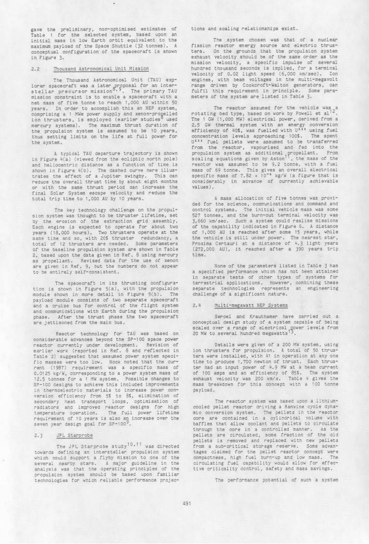
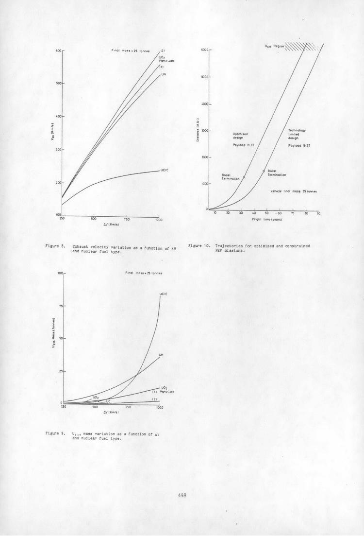
for given values of K the minima in this function From this analysis, the "ultimate perfor-are most conveniently derived numerically. Figures mance" of nuclear electric systems seems to be to7 to 9 show the effect of AV on initial mass, achieve a AV of about 500 km/s in about 30 to 35exhaust velocity and fuel inventory at the optimum years. An optimum vehicle with a final mass of 25value of Ve . The clear superiority of the UO, tonnes would have the approximate characteristicsparticulate fuels is evident, provided that thruster shown in Table 8.technology is adequate to deliver the optimumexhaust velocity. This vehicle could reach the Oort regions
(- 6000 AU) in a period of about 80 years. Acceler-3.4 Acceleration Time Optimisation ation would cease at about 1260 AU. The optimisa-
tion for this mission showed a requirement for anUsing the criterion of maximum payload mass exhaust velocity of 308 km/s. This may well be
flow into the mission the optimum is easily found as achievable, but is outside the range of thrusters sofollows. We can write approximately far studied by us as indicated in Table 5. A second
vehicle was therefore examined for the same mission
u mf nth ne (ps th - At mp - An "n (AV - 500 Km/s) but this time employing the thrusterb shown in Table 5. This vehicle again had a final
mass of 25 tonnes. Its characteristics are shown inwhere Ap is the power supply specific mass Table 9. It is seen that whilst the payload is
(kg/W) reduced by 23% and the initial mass increased by a
493

factor of 2.78, the U,,, inventory has only risen by In conclusion, it seems feasible to explore20%. Flight times have been extended by about 15 the currently understood limits of the solar system,years. out to the Oort region with advanced nuclear elec-
tric propulsion systems on a timescale of less thanThus it can be argued that even this vehicle a century. The technology base required already has
which carries restraints for realistic fuel and foundations and could probably be brought to frui-thruster technology is still capable of missions to tion by AD 2025.about 6000-6500 AU in a useful flight time. Thetime distance trajectories of these two vehicles areshown in Figure 10. These compare favourably withprevious studies, but we would argue, at technologylevels which may be realised within the time frame Table 3over which nuclear electric propulsion remains Optimised Starprobe Performancecompetitive, i.e. before more advanced systems of Characteristicspropulsion having better specific mass appear.
Since the optimum acceleration period is Specific impulse (sec) 400,000directly proportional to system specific mass it is Thrust (newton) 500clearly of interest to reduce it. However the Engine input power (MW) 1,0000.002 kg/W for the power supply here in the several Ion beam current (A) 60.1MW(e) range is already an advanced target. By oper- Ion beam energy (MeV) 16.7ating the particulate fuel at very high temperature Initial vehicle mass (tonne) 427and exploiting advanced technology for conversion Burn time (yr) 64.9and waste heat radiation this could conceivably fall Terminal velocity (km/sec) 3,660but it is unlikely to drop below 0.001 kg/W over the Terminal velocity (c) 0.0122next few decades, by which time other propulsionsystems will probably be feasible.
Table 1Mass and Performance Estimates for the
Interstellar Precursor Mission Table 4Multi-megawatt NEP System
Allocation Mass (kg)Parameter Mass (tonne)
Net spacecraft 1,200Pluto probe 1,500 POWER SUPPLY 161Power and propulsion (dry) 8,500Total propellant (Hg) 20,200 Reactor system 8Tankage 600 Radiator 75
Turbine 26Total mass 32,000 Boiler and piping 30
Alternator 7Performance Structure 15Burn-out distance (AU) 65Hyperbolic velocity (km/sec) 105 PROPULSION SYSTEM 46Time from launch at burn-out (yr) 8Distance in 20 yr (AU) 370 Thrusters and gimbal 5Distance in 50 yr (AU) 1030 Power processing unit 13
Propellant tank 26Structure 2
Table 2TAU Baseline Propulsion System PROPELLANT 1,200
PAYLOAD 100Parameter 1985 Study Data
TOTAL SPACECRAFT MASS 1,507Ion Engine
Input power (kW) 490Specific impulse (sec) 20,000Thrust (N) 4.54Beam current (A) 10.5Beam voltage (kV) 46.4Discharge loss (W/A) 250 Table 5Propellant utilisation 0.95 Advanced Thruster CharacteristicsBeam diameter 0.54Propellant Hg
Propellant ArgonPower Unit Beam voltage (kV) 9
Input power (kW) 500 Exhaust velocity 188Specific mass (kg/W) 0.00098 Beam current (A) 320Efficiency 0.98 Thrust (N) 27.5
Beam power (kW) 2,880System Specifications Discharge loss (W/A) 100
Total input power (kW) 1,000 Total power (kW) 2,912Total thrust (N) 9.08 Power efficiency 0.989Total efficiency 0.89 Propellant efficiency 0.9Total mass (kg) 3439 Total efficiency 0.890Specific mass (kg/W) 0.00344 Thruster diameter (m) 0.5
494

Table 6Fission Reactor Fuel Parameters
Energy EnergyDensity atom Maximum Atoms release releaseFuel Density density burned(kg/m') ( 3 burn-up density density
(J/m') (J/kg)-K
UO, metal cladding 10970 2.475.10" 5 1.24x10" 3.774.10" 3.44x10²
UN " " 14300 3.45910'" 5 1.73x10" 5.266.10" 3.68.101
UC " " 11700 2.721x10" 5 1.36.1027 4.140x101 3.54x10¹²
UC " 13600 3.316x10" 5 1.66x10 " 5.053«10" 3.72102
UC/C matrix 1800 3.102S 45 1.35x10² 4.109x10" 2.2810"
UO, particulate (1) 4483 7.34 1027 12.5 9.18x10" 2.794x10" 6.23x10"
UO, particulate (2) 3201 3.49x10 "2 50.0 1.75«1027 5.327x10'6 16.64.1012
Table 7Optimum Flight Time Mission Parameters
Mission Velocity (km/s)
250 500 1000
Fuel Part.(1) Part.(2) Part.(1) Part.(2) Part.(1) Part.(2)
E/Mf (J/kg) 2.741x10" 2.722x10" 1.133x10" 1.103 x10" 5.153 x101 2 4.63210'2
mp/mf 4.025 3.982 4.351 4.137 5.755 4.550
m n/mf 0.044 0.016 0.182 0.066 0.827 0.278
Ve (m/s) 155700 156000 304500 308000 564600 602000
tb (years) 7.95 7.84 34.1 32.2 189.1 143.29
Power (MW(e)) 5.47 5.50 5.26 5.43 4.32 5.12
Acceleration 156.4 154.0 1347.6 1265.1 15,053 11,350
Range (AU)
mu/mf 0.455 0.459 0.438 0.452 0.360 0.427
t 0.02 0.02 0.02 0.02 0.02 0.02
n 0.2 0.2 0.2 0.2 0.2 0.2
Table 8 Table 9Approximate Characteristics of an Approximate Characteristics of Thruster
Optimised Deep Space Probe Technology Constrained Deep Space Probe
Initial mass (T) 130.1 Initial mass (T) 361.6
Propellant mass (T) 103.4 Propellant mass (T) 334.6Nuclear fuel mass (T) 1.7 Nuclear fuel mass (T) 2.0
U,,, mass (kg) 705 U,, mass (kg) 843Tankage mass (T) 2.1 Tankage mass (T) 6.7Refuelling kit mass (T) 0.3 Refuelling kit mass (T) 0.4Power supply mass (T) 9.66 Power supply mass (T) 7.9Thruster mass (T) 1.64 Thruster mass (T) 1.3Payload mass (T) 11.30 Payload mass (T) 8.7Electrical power (MWe) 5.4 Electrical power (MWe) 4.4
Acceleration time (years) 32.2 Acceleration time (years) 47.3Exhaust velocity (km/s) 308 Exhaust velocity (km/s) 188.3
495

REFERENCES
1. A. R. Martin and A. Bond, A review and assess-ment of the performance of advanced ion thrus- 140 140ters, Paper No. IAF-85-202, Stockholm, October1985. 120 - - 20
2. A. R. Martin and A. Bond, Solar system mission S100 - 100capabilities of advanced ion thrusters, PaperNo. IAF-86-176, Innsbruck, October 1986. o - so
3. L. R. Shepherd and A. V. Cleaver, The atomic 60 60rocket, p.136 in L. J. Carter (Ed.) Realitiesof Space Travel, Putnam, London, 1957.
40- 40
4. L. R. Shepherd, Interstellar flight, JBIS, 11,149 (1952). 20 - 20
5. L. D. Jaffe et al, An interstellar precursor 0 6 -- i i-i L 0
mission, JPL Publication 77-70, October 1977. 2 4 6 10 12 14 16 18
Net spacecraft mass (tann6. L. D. Jaffe et al, An interstellar precursor
mission, JBIS, 33, 3 (1980).Figure 1. Performance of Interstellar Precursor Mission
7. W. M. Phillips and E. V. Pawlik, Design con- NEP System.siderations for a nuclear electric propulsionsystem, AIAA Paper No. 78-691, April 1978.
8. G. Aston, Ion propulsion technology require- ION THRUSTERSments for planetary mission applications, AIAA TO PRIMARYPaper No. 85-2000, September 1985. RADIATOR THERMIONC.
,-' " \ 1
tV ) /- THERMIONIC
9. K. T. Nock, TAU - A mission to a thousand ast- CONVERTER
ron6mical units, AIAA Paper No. 87-1049, May MA
1987. LiH NEUTRON
10. G. Aston, Electric propulsion: A far reachingtechnology, AIAA Paper No. 85-2028, September1985. REACTOR
11. G. Aston, Electric propulsion: A far reachingtechnology, JBIS, 39, 503 (1986).
12. J. Powell, T. Botts, C. M. Stickley and TYPICAL EATS. Meth, The rotating bed reactor as a power PIPE PATHsource for EM gun applications, IEEE Trans. onMagnetics, MAG-18, 135 (1982).
13. J. Sercel and S. Krauthamer, Multi-megawatt Figure 2. Nuclear-thermionic power system.nuclear electric propulsion; First order systemdesign and performance evaluation, AIAA PaperNo. 86-1202, June 1986.
14. A. R. Martin, High power beams for neutralinjection heating, Vacuum, 34, 17 (1984).
Figure 3. Conceptual design of the Interstellar Precursormission spacecraft.
496
misio saccrft
496ur''"ur

SOLAR SYSTEMESCAPE DIRECTION PROXIMA CENTAURI
- 389 YEARS--
/ LAUNCH
I EARTH ESCAPE IL 250d
) - - OORT CLOUD
\ -100 YEARS
EARTH ORBIT
0.1-
100d ACHIEVE SOLAR PROPULSION
SYSTEM ESCAPE SYSTEM SHUTVELOCITY IL*9dl DOWN - 65 YEARS
SISTARPROBE TERMINAL
Sc VELOCITY 0.01220c
1001
* 5000 kg SPACECRAFT /
* 10 mt PROPULSION SYSTEM / /
* 250 knm/I EXHAUST VELOCITY /
* 10 yer BURN TIME / / HELIOPAUSE - 5.0 YEARS* 1 MW REACTOR / 0.001 --X /
S/ PLUTO-3.3 YEARS
S</ SATURN -L5 YEARS
S10 100
o // TRIP TIME-YEARS
S _ I I I Figure 6. JPL Starprobe mission capability.
0 10 20 30 40 50
TIME FROM LAUNCH, ymr
UC/C F'nOl mCns Stonnm
Figure I. TAU trajectory example (a) Solar System escape, n
(b) heliocentric distance as a function of time. 1000
PAYLOAD MOOUL
SPIN SCIENCE ANDCOMMUNICATIONS S/C
ASTRONOMY S/C 75NUCLIAR IONPROPULSIOINRIACTO R MOOU.LEUI
I - O1 500 -
REACTOR FLIGHT SYSTEM PAYLOAO MODULECO CO CO -
PROPULSION MOOULIIONITHRUSTER 250 UN
REACTION ATTITUOR 1/ UC2
IOI
'b/
ONENGINE INSULATSO _ _ _ _
XTEON 250 500 n5 1000
Figure 7. Initial mass variation as a function of AVFORWARO D and nuclear fuel type.BOOM
Figure 5. TAU spacecraft configuration (a) cSoplete vehicle
in thrLuting mode. (b) detail of ion propulsion
module.
497
600- Fnal m,.* 25 ltoneS (2) 6000 Oo \ Reg \\\ \
(1)
UNS5000
500 -
SX3000 - Tchnoloy
300 -
0000 -
UC/C B oostBoost TefmintionTermnation
200 -^ 1000-
Vehicle hnal mass 21 Ionnr
0
100 0 20 30 40 50 - 60 70 80 9250
50 750 1000 Flight tm(e lywors)
AV IKml)
Figure 8. Exhaust velocity variation as a function of AV Figure 10. Trajectories for optimised and constrained
and nuclear fuel type. NEP misslons.
100r F
;nO mas .2 to nl
uc/c
79 -
so
UN
(1) Par;-t
UO (2)0 -UC
250 500 750 1000
AV I mlis
Figure 9. Un, mass variation as a function of AVand nuclear fuel type.
498