ul instrumentation cable high-temperature …. bare tinned insulation/jacket ab pvc-nylon/pvc cd...
TRANSCRIPT

I N D U S T R I A L A U T O M A T I O N & P R O C E S S C O N T R O L C A B L E S 18.55
18•
Indu
stria
l Cab
les
F o r m o r e i n f o r m a t i o n , c o n t a c t B e l d e n Te c h n i c a l S u p p o r t : 1 - 8 0 0 - B E L D E N - 1 • w w w . b e l d e n . c o m
UL Instrumentation CableHigh-Temperature Thermocouple Extension Cables and Thermocouple WireIndustrial Grade Sunlight- and Oil-Resistant Jackets
High-Temp Extension Cable • 20 AWG Solid Conductors • (See chart on page 18.53 for conductor specifications by ANSI Type)
Plenum • Unshielded • FEP Insulation • FEP Jacket300V 200°C 83932 KX 2/c Yellow, Red Yellow 500 † 152.4 6.5 3.0 .010 .25 .076 1.93NEC: PLTC, CL3P 1000 † 304.8 12.0 5.4 x x
.128 3.25
83934 TX 2/c Blue, Red Blue 1000 † 304.8 13.0 6.0 .010 .25 .076 1.93x x
.128 3.25
High-Temp Extension Cable • 20 AWG Stranded (7x28) Conductors • (See chart on page 18.53 for conductor specifications by ANSI Type)
Plenum • Unshielded • FEP Insulation • FEP Jacket300V 200°C 83930 JX 2/c White, Red Black 500 † 152.4 7.5 3.4 .010 .25 .082 2.08NEC: PLTC, CL3P 1000 † 304.8 13.0 6.0 x x
.140 3.56
Plenum • Overall Beldfoil® Shield (100% Coverage) • FEP Insulation • FEP Jacket300V 200°C 83955 EX 1 pr. Purple, Red Purple 500 † 152.4 9.0 4.1 .010 .25 .145 3.68NEC: PLTC, CL3P 1000 † 304.8 16.0 7.3
83950 JX 1 pr. White, Red Black 500 † 152.4 9.5 4.3 .010 .25 .145 3.681000 † 304.8 16.0 7.3
83952 KX 1 pr. Yellow, Red Yellow 500 † 152.4 9.5 4.3 .010 .25 .145 3.681000 † 304.8 16.0 7.3
83954 TX 1 pr. Blue, Red Blue 500 † 152.4 9.0 4.1 .010 .25 .145 3.681000 † 304.8 17.0 7.7
High-Temp Extension Cable • 16 AWG Pairs Solid Conductors • (See chart on page 18.53 for conductor specifications by ANSI Type)
Plenum • Overall Beldfoil Shield (100% Coverage) • FEP Insulation • FEP Jacket300V 200°C 1114A EX 1 Purple, Red Purple 5000 † 1524.0 160.0 72.6 .010 .25 .172 4.37NEC: PLTC, CL3P 1115A JX 1 White, Red Black 5000 † 1524.0 155.0 70.4 .010 .25 .172 4.37
1116A KX 1 Yellow, Red Yellow 5000 † 1524.0 160.0 72.6 .010 .25 .171 4.34
1117A TX 1 Blue, Red Blue 5000 † 1524.0 160.0 72.6 .010 .25 .172 4.37
High-Temp Extension Cable • 16 AWG Pairs Stranded (7x24) Conductors • (See chart on page 18.53 for conductor specifications by ANSI Type)
Plenum • Overall Beldfoil Shield (100% Coverage) • FEP Insulation • FEP Jacket300V 200°C 83951 JX 1 White, Red Black 500 † 152.4 16.0 7.3 .010 .25 .189 4.80NEC: PLTC, CL3P 1000 † 304.8 35.0 15.9
83953 KX 1 Yellow, Red Yellow 500 † 152.4 16.0 7.3 .010 .25 .187 4.751000 † 304.8 32.0 14.5
High-Temp Thermocouple Wire • 20 AWG Solid Conductors • (See chart on page 18.53 for conductor specifications by ANSI Type)
Plenum • Unshielded • FEP Insulation • FEP Jacket300V 200°C 83915 E 2/c Purple, Red Brown 500 † 152.4 7.0 3.2 .010 .25 .076 1.93NEC: PLTC, CL3P 1000 † 304.8 13.0 6.0 x x
.128 3.25
83900 J 2/c White, Red Brown 100 30.5 2.1 1.0 .010 .25 .076 1.93500 † 152.4 7.0 3.2 x x
1000 † 304.8 13.0 6.0 .128 3.25
83905 K 2/c Yellow, Red Brown 100 30.5 2.1 1.0 .010 .25 .076 1.93500 † 152.4 7.0 3.2 x x
1000 † 304.8 12.0 5.4 .128 3.25
83910 T 2/c Blue, Red Brown 100 30.5 2.1 1.0 .010 .25 .076 1.93500 † 152.4 7.0 3.2 x x
1000 † 304.8 12.0 5.4 .128 3.25
FEP = Fluorinated Ethylene-propylene Multiple pair cables have each pair numbered for ease of identification.†Final put-up length may vary ±10% from length shown.
JacketColor
Inch mm
Nominal OD
Standard Lengths
Ft.
ColorCode
No.of
Pairs/Cond. Inch mm
InsulationThicknessPart
No.Descriptionm
StandardUnit WeightANSI
TypeLbs. kg
Drain Wire
Drain Wire
Drain Wire

I N D U S T R I A L A U T O M A T I O N & P R O C E S S C O N T R O L C A B L E S 18.56
F o r m o r e i n f o r m a t i o n , c o n t a c t B e l d e n Te c h n i c a l S u p p o r t : 1 - 8 0 0 - B E L D E N - 1 • w w w . b e l d e n . c o m
UL Instrumentation Cable600V Tray Cables – Overview
Construction
Soft annealed bare or tinned copper conductors. PVC insulated with a nylon overcoat, 90°C PVC Jacket, TFN,TFFN or THHN style singles. Nylon rip cord included in all PVC-Nylon/PVC instrumentation cables.
Application
These cables are suitable for installation in wet or dry locations. Cable jackets areresistant to sunlight, moisture and vaporpenetration. The cables can be used in raceways, and (supported by messengerwire), outdoor applications and direct burial applications.
Unshielded
Twisted non-shielded instrument pairs provide a minimal OD allowing greater trayand conduit fill. Non-shielded instrumentpairs may be utilized when recommendedby the instrument manufacturer and used in a metallic conduit.
Overall Shield
Recommended for use in instrumentationapplications where signals are transmitted in excess of 100 millivolts except in areaswhere high voltage and current sourcescreates excessive noise interference.
The Beldfoil® shield with drain wire provides 100% coverage for maximumshield effectiveness. Copper tape shieldavailable upon request.
Individually Shielded and Overall Shielded
Individually shielded pairs or triads with an overall shield are recommended for use in instrumentation applications whereoptimum noise rejection is required. Individualpair/triad shields are fully isolated fromeach other and contain a separate drainwire for grounding, to provide maximumprotection from crosstalk and commonmode interference. Cables with an overallshield provide additional electrostatic noise protection.
Specifications UL Subject 1277 TC UL1685 (UL1581) Vertical Tray Flame
Test comparable to IEEE 383-1974 (70,000 BTU/hr.) Flame Test
NEC Type TC Listed, which is approvedfor cable tray use in Class 1, Division 2areas, per NEC Articles 340, 318 and501 and for Class 1 circuits as permittedin Article 725
PVC-nylon/PVC constructions are NEC Type NPLF Listed, which isapproved for use in Non Power-LimitedFire Protective Signaling circuits, per NEC Article 760
PVC-Nylon/PVC, XLPE/PVC and XLPE/CPE constructed cables meet IEEE 1202/IEEE 383-2003/FT4 (70,000 BTU) Flame Test
XLPE/Haloarrest cables are UL 1277 TC-LS rated
TC-ER Rated Cables
As an option, Belden offers all PVC-nylon/PVC, XLPE/PVC and XLPE/CPE jacketedtray cables with a TC-ER (Exposed Run)rating, formerly referred to as Open Wiring.
Per NEC Article 336, a TC-ER rated cablemay be installed in an industrial establishmentbetween a cable tray and the utilizationequipment or device. A TC-ER rated cablemust meet the crush and impact require-ments of UL Type MC cable. By eliminatingthe need for metal conduit and/or armor,using a TC-ER rated cable results in savings in both installation and maintenance.
MC Cable Ratings Optional
Customize any 600V TC instrumentationcable, with armor and a full-sized ground.See chart below to specify.
Armor
Code Material2 Aluminum Interlock3 Steel Interlock
Overall Jacket
Code Material1 PVC3 CPE4 TPE5 HDPE6 Oil Res II7 Haloarrest
1 2 3456 AOverall Armor Core Conductor,Jacket Type 4-digit Insulation,Type Part No. Inner Jacket
600V TC TypeInstrumentation
To Specify MC Rated Cable
Standard lengths may be subject to tolerance. Custom lengths may be available upon request. Contact the Belden Electronics Division CustomerService Department for additional information. 1-800-BELDEN-1.
Bare Tinned Insulation/JacketA B PVC-Nylon/PVCC D XLPE/PVCE F FRPO/PVCG H XLPE/TPEK L TPE/TPEM N PVC-Nylon/Oil Res IIQ R XLPE/CPES T XLPE/Haloarrest
*For 1000 and 3000 Series cables only.
1234 AStart Add or with replace Part letterNo. code
To Specify:
Tray Cable Construction Options
UL Listed for MC and TC
Insulation/Jacket Flame Tests Ratings*Max. Temp Rating
Wet DryPVC-Nylon/PVC 75°C 90°C UL 1685 ICEA S-73-532(THHN or THWN) FT4/IEEE 1202/383 ICEA S-61-40214 AWG & larger ICEA T-29-520PVC-Nylon/PVC N/A 90°C UL 1685 ICEA S-73-532(TFN or TFFN) FT4/IEEE 1202/383 ICEA S-61-40216 & 18 AWG ICEA T-29-520XLPE/PVC or CPE 90°C 90°C UL 1685 ICEA S-73-532(XHHW–2) FT4/IEEE 1202/383 ICEA S-66-52414 AWG & larger VW-1 rated singles
ICEA T-29-520XLPE/PVC or CPE 75°C 75°C UL 1685 ICEA S-73-532(RFH–2) FT4/IEEE 1202/383 ICEA S-66-52416 & 18 AWG VW-1 rated singles ICEA S-82-552
ICEA T-29-520FRPO/PVC — 75°C UL 168518 AWG & largerTPE/TPE 75°C 90°C UL 1685FRPO/PVC 75°C 90°C UL 1685XLPE/Haloarrest® 90°C 90°C UL 1685 TC-LS(XHHW-2) ICEA T-29-52014 AWG & larger FT4/IEEE 1202/383XLPE/Haloarrest 75°C 75°C UL 1685 TC-LS(RFH-2) ICEA T-29-52016 & 18 AWG FT4/IEEE 1202/383FEP/PVC 90°C 90°C UL 1685CPE = Chlorinated Polyethylene • FEP = Fluorinated Ethylene-propylene • FRPO = Flame-retardant Polyolefin •PVC = Polyvinyl Chloride • TPE = Thermoplastic Elastomer • XLPE = Cross-linked Polyethylene*Applicable to TC-rated cables only.
Conductor, Insulation and Jacket Options*

I N D U S T R I A L A U T O M A T I O N & P R O C E S S C O N T R O L C A B L E S 18.57
18•
Indu
stria
l Cab
les
F o r m o r e i n f o r m a t i o n , c o n t a c t B e l d e n Te c h n i c a l S u p p o r t : 1 - 8 0 0 - B E L D E N - 1 • w w w . b e l d e n . c o m
UL Instrumentation Cable600V Tray CablesIndustrial Grade Sunlight- and Oil-Resistant Jackets
18 AWG Pairs Stranded (19x30) Tinned Copper Conductors • Twisted Pairs
Unshielded • PVC/Nylon Insulation • Black PVC Jacket9486 1 E2 1000 304.8 43.0 19.5 .048 1.22 .275 6.99 50 222 2.75 69.85
Overall Beldfoil® Shield (100% Coverage) • PVC/Nylon Insulation • Black PVC Jacket 9341 1 E2 500 152.4 22.0 10.0 .048 1.22 .276 7.01 63 280 2.75 69.85
1000 304.8 43.0 19.5
18 AWG Pairs Stranded (7x26) Bare Copper Conductors • Twisted Pairs
Overall Beldfoil Shield (100% Coverage) • PVC/Nylon Insulation • Black PVC Jacket (See chart below for other options)1120A 1 E2 10000 † 3048.0 450.0 204.3 .048 1.22 .278 7.06 59 262 2.80 71.12
3088A 1 E1 10000 † 3048.0 510.0 231.3 .048 1.22 .278 7.06 67 298 2.80 71.12
1063A 2 E1 10000 † 3048.0 790.0 358.3 .053 1.35 .407 10.34 112 498 4.10 104.14
1064A 4 E1 7500 † 2286.0 892.5 404.8 .053 1.35 .470 11.94 202 899 4.70 119.38
1065A 8 E1 7500 † 2286.0 1650.0 748.4 .064 1.63 .599 15.21 381 1695 6.00 152.40
1066A 12 E1 5000 † 1524.0 1520.0 689.5 .064 1.63 .717 18.21 560 2491 7.20 182.88
1067A 16 E1 5000 † 1524.0 1905.0 864.1 .064 1.63 .793 20.14 739 3287 8.00 203.20
1068A 24 E1 2500 † 762.0 1487.5 674.7 .084 2.13 1.017 25.83 1098 4884 10.30 261.62
1087A 36 E1 1250 † 381.0 1005.0 455.9 .084 2.13 1.178 29.97 1635 7273 11.70 297.18
1088A 50 E1 Bulk †† Bulk — — .084 2.13 1.446 36.73 2262 10062 14.50 368.30
Individually Shielded + Overall Beldfoil Shield (100% Coverage) • PVC/Nylon Insulation • Black PVC Jacket (Options below)
1048A 2 E1 7500 † 2286.0 622.5 282.4 .048 1.22 .381 9.68 140 623 3.80 96.52
1049A 4 E1 7500 † 2286.0 1057.5 479.7 .053 1.35 .489 12.42 258 1148 4.90 124.46
1050A 8 E1 7500 † 2286.0 1965.0 891.3 .064 1.63 .654 16.61 350 1557 6.60 167.64
1051A 12 E1 5000 † 1524.0 1915.0 868.6 .064 1.63 .785 19.94 728 3238 7.90 200.66
1052A 16 E1 2500 † 762.0 1267.5 574.9 .084 2.13 .898 22.81 963 4284 9.00 228.60
1053A 24 E1 2500 † 762.0 1907.5 865.2 .084 2.13 1.115 28.32 1434 6379 11.10 281.94
1054A 36 E1 1250 † 381.0 1270.0 576.1 .084 2.13 1.299 32.99 2139 9515 13.00 330.20
1038A 50 E1 Bulk †† Bulk — — .084 2.13 1.527 38.79 2962 13176 15.30 388.62E1, E2 = Refer to Technical Information section for color code. Alternate color coding available upon request. Multiple pair or triad cables have each pair/triad numbered for ease of identification.†Final put-up length may vary ±10% from length shown.††Bulk = Check length available for specific construction.
Standard Lengths
Ft.
ColorCode
mm
Jacket Thickness
Inch mm
Nominal OD
Lbs. N
MaximumPull Tension
Inch
PartNo.Description
MinimumBend Radius
m
StandardUnit WeightNo.
ofPairs Lbs. kg Inch mm
Conductor, Insulation and Jacket Options**
Bare Tinned Insulation/JacketA B PVC-Nylon/PVCC D XLPE/PVCE F FRPO/PVCG H XLPE/TPEK L TPE/TPEM N PVC-Nylon/Oil Res IIQ R XLPE/CPES T XLPE/Haloarrest®
**For 1000 and 3000 Series cables only.
Rip Cord
Rip Cord
Rip Cord
Rip CordDrain Wire
Drain Wires
Drain Wire
NEC: TC, NPLFICEA S-73-532, ICEA S-61-402ICEA T-29-520FT4/IEEE 1202/383
NEC: TC, NPLFICEA S-73-532, ICEA S-61-402ICEA T-29-520FT4/IEEE 1202/383
NEC: TC, NPLFICEA S-73-532ICEA S-61-402ICEA T-29-520FT4/IEEE 1202/383
NEC: TC, NPLFICEA S-73-532ICEA S-61-402ICEA T-29-520FT4/IEEE 1202/383
1234 A EStart Add or Add for with replace ExposedPart letter code Run rating No. for desired if desired
conductor,insulation & jacket
To Specify:

18 AWG Pairs Stranded (7x26) Bare Copper Conductors • Twisted Pairs
Overall Beldfoil Shield (100% Coverage) • PVC/Nylon Insulation • Black PVC Jacket (Green Ground)3088AE 1 E1 1000 3048.0 63.0 28.6 .048 1.22 .340 8.64 80 356 3.40 86.36
5000 † 1524.0 320.0 145.3
Overall Beldfoil Shield (100% Coverage) • XLPE Insulation • Black PVC Jacket (Green Ground)3088CE 1 E1 1000 3048.0 66.0 30.0 .048 1.22 .340 8.64 80 356 3.40 86.36
5000 † 1524.0 375.0 170.3
18 AWG Triads Stranded (7x26) Bare Copper Conductors • Twisted Triads
Overall Beldfoil® Shield (100% Coverage) • PVC/Nylon Insulation • Black PVC Jacket (See chart below for other options)1121A 1 E2 500 † 152.4 27.5 12.5 .048 1.22 .282 7.16 90 400 2.75 69.85
1000 † 304.8 53.0 24.010000 † 3048.0 560.0 254.0
3089A 1 E1 10000 † 3048.0 590.0 267.6 .048 1.22 .284 7.21 90 400 2.75 69.85
Individually Shielded + Overall Beldfoil Shield (100% Coverage) • PVC/Nylon Insulation • Black PVC Jacket (Options below)3064A 2 E1 Bulk †† Bulk — — .048 1.22 .493 12.52 185 823 4.75 120.65
1093A 4 E1 7500 † 2286.0 1545.0 700.8 .063 1.60 .577 14.66 347 1544 6.00 152.40
1094A 8 E1 5000 † 1524.0 1755.0 796.1 .063 1.60 .745 18.92 672 2989 7.50 190.50
1095A 12 E1 2500 † 762.0 1320.0 598.8 .084 2.13 .944 23.98 997 4435 9.75 247.655000 † 1524.0 2875.0 1304.1
3066A 16 E1 Bulk †† Bulk — — .084 2.13 1.046 26.57 1322 5881 10.50 266.70
1096A 24 E1 Bulk †† Bulk — — .084 2.13 1.284 32.61 1971 8767 13.00 330.20
E1, E2 = Refer to Technical Information section for color code.Alternate color coding available upon request.
Multiple pair or triad cables have each pair/triad numbered for ease of identification.†Final put-up length may vary ±10% from length shown.††Bulk = Check length available for specific construction.
I N D U S T R I A L A U T O M A T I O N & P R O C E S S C O N T R O L C A B L E S 18.58
F o r m o r e i n f o r m a t i o n , c o n t a c t B e l d e n Te c h n i c a l S u p p o r t : 1 - 8 0 0 - B E L D E N - 1 • w w w . b e l d e n . c o m
UL Instrumentation Cable600V Tray CablesIndustrial Grade Sunlight- and Oil-Resistant Jackets
Conductor, Insulation and Jacket Options
Bare Tinned Insulation/JacketA B PVC-Nylon/PVCC D XLPE/PVCE F FRPO/PVCG H XLPE/TPEK L TPE/TPEM N PVC-Nylon/Oil Res IIQ R XLPE/CPES T XLPE/Haloarrest®
Standard Lengths
Ft.
ColorCode
mm
Jacket Thickness
Inch mm
Nominal OD
Lbs. N
MaximumPull Tension
Inch
PartNo.Description
MinimumBend Radius
m
StandardUnit Weight
No.of
Pairs/Triads Lbs. kg Inch mm
Rip CordDrain Wire
Drain WiresRip Cord
NEC: TC, NPLFICEA S-73-532ICEA S-61-402ICEA T-29-520FT4/IEEE 1202/383
NEC: TC, NPLFICEA S-73-532ICEA S-61-402ICEA T-29-520FT4/IEEE 1202/383
1234 A EStart Add or Add for with replace ExposedPart letter code Run rating No. for desired if desired
conductor,insulation & jacket
To Specify:
Rip CordDrain Wire
NEC: TC-ER, NPLF ICEA S-73-532 ICEA S-61-402ICEA T-29-520FT4/IEEE 1202/383
NEC: TC-ER, NPLFICEA S-73-532ICEA S-66-524ICEA T-29-520FT4/IEEE 1202/383
Ground
Rip CordDrain Wire
Ground

I N D U S T R I A L A U T O M A T I O N & P R O C E S S C O N T R O L C A B L E S 18.59
18•
Indu
stria
l Cab
les
F o r m o r e i n f o r m a t i o n , c o n t a c t B e l d e n Te c h n i c a l S u p p o r t : 1 - 8 0 0 - B E L D E N - 1 • w w w . b e l d e n . c o m
UL Instrumentation Cable600V Tray CablesIndustrial Grade Sunlight- and Oil-Resistant Jackets
Standard Lengths
Ft.
ColorCode
mm
Jacket Thickness
Inch mm
Nominal OD
Lbs. N
MaximumPull Tension
Inch
PartNo.Description
MinimumBend Radius
m
StandardUnit WeightNo.
ofPairs Lbs. kg Inch mm
16 AWG Pairs Stranded (19x29) Tinned Copper Conductors • Twisted Pairs
Unshielded • PVC/Nylon Insulation • Black PVC Jacket9487 1 E2 500 152.4 25.5 11.6 .048 1.22 .295 7.49 70 311 3.00 76.20
1000 304.8 54.0 24.5
Overall Beldfoil® Shield (100% Coverage) • PVC/Nylon Insulation • Black PVC Jacket9342 1 E2 500 152.4 27.5 12.7 .048 1.22 .296 7.52 105 467 3.00 76.20
1000 304.8 56.0 25.4
16 AWG Pairs Stranded (7x24) Bare Copper Conductors • Twisted Pairs
Overall Beldfoil Shield (100% Coverage) • PVC/Nylon Insulation • Black PVC Jacket (See chart below for other options)1118A 1 E2 10000 † 3048.0 550.0 249.5 .047 1.19 .294 7.47 105 467 3.00 76.20
3090A 1 E1 2500 † 762.0 150.0 68.0 .047 1.19 .295 7.49 105 467 3.00 76.20
1069A 2 E1 7500 † 2286.0 712.5 323.2 .047 1.19 .456 11.58 179 796 4.60 116.84
1527A 3 E1 7500 † 2286.0 1042.5 472.9 .047 1.19 .482 12.24 241 1072 4.80 121.92
1070A 4 E1 7500 † 2286.0 1357.5 615.8 .063 1.60 .560 14.22 321 1428 5.60 142.24
1071A 8 E1 7500 † 2286.0 2242.5 1017.2 .063 1.60 .676 17.17 607 2700 6.80 172.72
1072A 12 E1 5000 † 1524.0 1047.5 475.2 .063 1.60 .812 20.63 893 3972 8.10 205.74
1073A 16 E1 2500 † 762.0 1442.5 654.3 .085 2.16 .946 24.03 1178 5240 9.30 236.22
1074A 24 E1 1250 † 381.0 2115.0 959.4 .085 2.16 1.158 29.41 1749 7780 11.60 294.64
1089A 36 E1 1250 † 381.0 1388.7 629.9 .085 2.16 1.321 33.55 2606 11592 13.20 335.28
1090A 50 E1 Bulk †† Bulk — — .085 2.16 1.551 39.40 3606 16040 15.50 393.70
Individually Shielded + Overall Beldfoil Shield (100% Coverage) • PVC/Nylon Insulation • Black PVC Jacket (Options below)1055A 2 E1 7500 † 2286.0 885.0 401.8 .047 1.19 .476 12.09 223 992 4.16 105.66
1037A 3 E1 7500 † 2286.0 1072.5 486.5 .047 1.19 .504 12.80 290 1290 5.00 127.0
1039A 4 E1 7500 † 2286.0 1472.5 667.9 .063 1.60 .584 14.83 411 1828 5.80 147.32
1040A 6 E1 5000 † 1524.0 1435.0 650.9 .063 1.60 .682 17.32 428 1904 6.80 172.72
1041A 8 E1 5000 † 1524.0 1805.0 818.8 .063 1.60 .738 18.75 786 3496 7.40 187.96
1042A 12 E1 2500 † 762.0 1327.5 602.2 .085 2.16 .935 23.75 1161 5164 9.40 238.76
1043A 16 E1 2500 † 762.0 1765.0 800.6 .085 2.16 1.035 26.29 1537 6837 10.40 264.16
1044A 20 E1 2500 † 762.0 2062.5 935.6 .085 2.16 1.146 29.11 1912 8505 11.50 292.10
1045A 24 E1 1250 † 381.0 1241.3 563.1 .085 2.16 1.272 32.31 2287 10173 12.70 322.58
1046A 36 E1 Bulk †† Bulk — — .085 2.16 1.454 36.93 3413 15182 14.50 368.30
1047A 50 E1 Bulk †† Bulk — — .120 3.05 1.781 45.24 4726 21022 17.80 452.12E1, E2 = Refer to Technical Information section for color code.Alternate color coding available upon request.
Multiple pair or triad cables have each pair/triad numbered for ease of identification.†Final put-up length may vary ±10% from length shown.††Bulk = Check length available for specific construction.
Rip Cord
Rip Cord
Rip Cord
Rip CordDrain Wire
Drain Wires
Drain Wire
NEC: TC, NPLFICEA S-73-532, ICEA S-61-402ICEA T-29-520FT4/IEEE 1202/383
NEC: TC, NPLFICEA S-73-532, ICEA S-61-402ICEA T-29-520FT4/IEEE 1202/383
NEC: TC, NPLFICEA S-73-532ICEA S-61-402ICEA T-29-520FT4/IEEE 1202/383
NEC: TC, NPLFICEA S-73-532ICEA S-61-402ICEA T-29-520FT4/IEEE 1202/383
Bare Tinned Insulation/JacketA B PVC-Nylon/PVCC D XLPE/PVCE F FRPO/PVCG H XLPE/TPEK L TPE/TPEM N PVC-Nylon/Oil Res IIQ R XLPE/CPES T XLPE/Haloarrest®
Conductor, Insulation and Jacket Options**
**For 1000 and 3000 Series cables only.
1234 A EStart Add or Add for with replace ExposedPart letter code Run rating No. for desired if desired
conductor,insulation & jacket
To Specify:

UL Instrumentation Cable600V Tray CablesIndustrial Grade Sunlight- and Oil-Resistant Jackets
I N D U S T R I A L A U T O M A T I O N & P R O C E S S C O N T R O L C A B L E S 18.60
F o r m o r e i n f o r m a t i o n , c o n t a c t B e l d e n Te c h n i c a l S u p p o r t : 1 - 8 0 0 - B E L D E N - 1 • w w w . b e l d e n . c o m
Standard Lengths
Ft.
ColorCode
mm
Jacket Thickness
Inch mm
Nominal OD
Lbs. N
MaximumPull Tension
Inch
PartNo.Description
MinimumBend Radius
m
StandardUnit Weight
No.of
Pairs/Triads Lbs. kg Inch mm
16 AWG Pairs Stranded (7x24) Bare Copper Conductors • Twisted Pairs
Overall Beldfoil Shield (100% Coverage) • PVC/Nylon Insulation • Black PVC Jacket (Green Ground)3090AE 1 E1 1000 304.8 65.0 29.5 .048 1.22 .390 9.91 130 578 3.90 99.06
5000 † 1524.0 340.0 154.4
Overall Beldfoil Shield (100% Coverage) • XLPE Insulation • Black PVC Jacket (Green Ground)3090CE 1 E1 1000 3048.0 81.0 39.8 .048 1.22 .390 9.91 130 578 3.90 99.06
5000 † 1524.0 450.0 204.3
16 AWG Triads Stranded (7x24) Bare Copper Conductors • Twisted Triads
Overall Beldfoil® Shield (100% Coverage) • PVC/Nylon Insulation • Black PVC Jacket (See chart below for other options)1119A 1 E2 500 † 152.4 35.0 15.9 .047 1.19 .310 7.87 129 574 3.10 78.74
1000 † 304.8 68.0 30.910000 † 3048.0 700.0 317.5
3091A 1 E1 10000 † 3048.0 750.0 340.2 .047 1.19 .310 7.87 129 574 3.10 78.74
Individually Shielded + Overall Beldfoil Shield (100% Coverage) • PVC/Nylon Insulation • Black PVC Jacket (Options below)1097A 4 E1 5000 † 1524.0 1415.0 641.8 .063 1.60 .640 16.26 554 2464 6.40 162.56
1098A 8 E1 2500 † 762.0 1350.0 612.4 .085 2.16 .872 22.15 1072 4768 8.70 220.98
1099A 12 E1 2500 † 762.0 1875.0 850.5 .085 2.16 1.047 26.59 1590 7073 10.50 266.70
3118A 16 E1 Bulk †† Bulk — — .084 2.13 1.234 31.34 1771 7878 12.25 311.15
1100A 24 E1 Bulk †† Bulk — — .085 2.16 1.434 36.42 3144 13985 14.30 363.22
3130A 36 E1 Bulk †† Bulk — — .110 2.79 1.773 45.03 3600 16013 18.00 457.20
E1, E2 = Refer to Technical Information section for color code.Alternate color coding available upon request.
Multiple pair or triad cables have each pair/triad numbered for ease of identification.†Final put-up length may vary ±10% from length shown.††Bulk = Check length available for specific construction.
Conductor, Insulation and Jacket Options
Bare Tinned Insulation/JacketA B PVC-Nylon/PVCC D XLPE/PVCE F FRPO/PVCG H XLPE/TPEK L TPE/TPEM N PVC-Nylon/Oil Res IIQ R XLPE/CPES T XLPE/Haloarrest®
Rip CordDrain Wire
Drain Wires
Rip Cord
NEC: TC, NPLFICEA S-73-532ICEA S-61-402ICEA T-29-520FT4/IEEE 1202/383
NEC: TC, NPLFICEA S-73-532ICEA S-61-402ICEA T-29-520FT4/IEEE 1202/383
1234 A EStart Add or Add for with replace ExposedPart letter code Run rating No. for desired if desired
conductor,insulation & jacket
To Specify:
NEC: TC-ER, NPLFICEA S-73-532ICEA S-66-524ICEA T-29-520FT4/IEEE 1202/383
NEC: TC-ER, NPLFICEA S-73-532ICEA S-61-402ICEA T-29-520FT4/IEEE 1202/383
Rip CordDrain Wire
Ground
Rip CordDrain Wire
Ground
I N D U S T R I A L A U T O M A T I O N & P R O C E S S C O N T R O L C A B L E S 18.61
18•
Indu
stria
l Cab
les
F o r m o r e i n f o r m a t i o n , c o n t a c t B e l d e n Te c h n i c a l S u p p o r t : 1 - 8 0 0 - B E L D E N - 1 • w w w . b e l d e n . c o m
UL Instrumentation Cable600V Tray CablesIndustrial Grade Sunlight- and Oil-Resistant Jackets
Standard Lengths
Ft.
ColorCode
mm
Jacket Thickness
Inch mm
Nominal OD
Lbs. N
MaximumPull Tension
Inch
PartNo.Description
MinimumBend Radius
m
StandardUnit Weight
No.of
Pairs/Triads Lbs. kg Inch mm
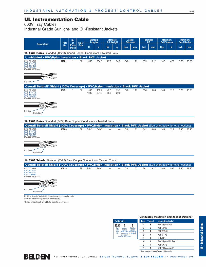
14 AWG Pairs Stranded (42x30) Tinned Copper Conductors • Twisted Pairs
Unshielded • PVC/Nylon Insulation • Black PVC Jacket9488 1 E2 1000 304.8 77.0 34.9 .048 1.22 .359 9.12 107 476 3.75 95.25
Overall Beldfoil® Shield (100% Coverage) • PVC/Nylon Insulation • Black PVC Jacket9343 1 E2 500 152.4 42.5 19.1 .048 1.22 .358 9.09 160 712 3.75 95.25
1000 304.8 86.0 39.0
14 AWG Pairs Stranded (7x22) Bare Copper Conductors • Twisted Pairs
Overall Beldfoil Shield (100% Coverage) • PVC/Nylon Insulation • Black PVC Jacket (See chart below for other options)3080A 1 E1 Bulk* Bulk* — — .048 1.22 .342 8.69 160 712 3.50 88.90
14 AWG Triads Stranded (7x22) Bare Copper Conductors • Twisted Triads
Overall Beldfoil Shield (100% Coverage) • PVC/Nylon Insulation • Black PVC Jacket (See chart below for other options)3081A 1 E1 Bulk* Bulk* — — .048 1.22 .361 9.17 200 890 3.50 88.90
E1, E2 = Refer to Technical Information section for color code.Alternate color coding available upon request.
*Bulk = Check length available for specific construction.
Rip Cord
Rip CordDrain Wire
Rip CordDrain Wire
Rip CordDrain Wire
Conductor, Insulation and Jacket Options**
Bare Tinned Insulation/JacketA B PVC-Nylon/PVCC D XLPE/PVCE F FRPO/PVCG H XLPE/TPEK L TPE/TPEM N PVC-Nylon/Oil Res IIQ R XLPE/CPES T XLPE/Haloarrest®
**For 1000 and 3000 Series cables only.
NEC: TC, NPLFICEA S-73-532ICEA S-61-402ICEA T-29-520FT4/IEEE 1202/383
NEC: TC, NPLFICEA S-73-532ICEA S-61-402ICEA T-29-520FT4/IEEE 1202/383
NEC: TC, NPLFICEA S-73-532ICEA S-61-402ICEA T-29-520FT4/IEEE 1202/383
NEC: TC, NPLFICEA S-73-532ICEA S-61-402ICEA T-29-520FT4/IEEE 1202/383
1234 A EStart Add or Add for with replace ExposedPart letter code Run rating No. for desired if desired
conductor,insulation & jacket
To Specify:
UL Instrumentation Cable600V Tray CablesIndustrial Grade Sunlight- and Oil-Resistant Jackets
I N D U S T R I A L A U T O M A T I O N & P R O C E S S C O N T R O L C A B L E S 18.62
F o r m o r e i n f o r m a t i o n , c o n t a c t B e l d e n Te c h n i c a l S u p p o r t : 1 - 8 0 0 - B E L D E N - 1 • w w w . b e l d e n . c o m
Standard Lengths
Ft.
ColorCode
mm
Jacket Thickness
Inch mm
Nominal OD
Lbs. N
MaximumPull Tension
Inch
PartNo.Description
MinimumBend Radius
m
StandardUnit Weight
No.of
Pairs/Triads Lbs. kg Inch mm
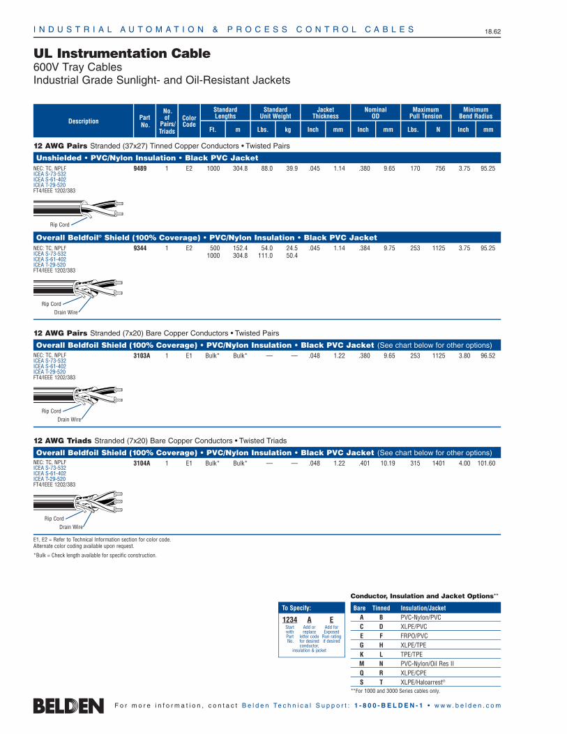
12 AWG Pairs Stranded (37x27) Tinned Copper Conductors • Twisted Pairs
Unshielded • PVC/Nylon Insulation • Black PVC Jacket9489 1 E2 1000 304.8 88.0 39.9 .045 1.14 .380 9.65 170 756 3.75 95.25
Overall Beldfoil® Shield (100% Coverage) • PVC/Nylon Insulation • Black PVC Jacket9344 1 E2 500 152.4 54.0 24.5 .045 1.14 .384 9.75 253 1125 3.75 95.25
1000 304.8 111.0 50.4
12 AWG Pairs Stranded (7x20) Bare Copper Conductors • Twisted Pairs
Overall Beldfoil Shield (100% Coverage) • PVC/Nylon Insulation • Black PVC Jacket (See chart below for other options)3103A 1 E1 Bulk* Bulk* — — .048 1.22 .380 9.65 253 1125 3.80 96.52
12 AWG Triads Stranded (7x20) Bare Copper Conductors • Twisted Triads
Overall Beldfoil Shield (100% Coverage) • PVC/Nylon Insulation • Black PVC Jacket (See chart below for other options)3104A 1 E1 Bulk* Bulk* — — .048 1.22 .401 10.19 315 1401 4.00 101.60
E1, E2 = Refer to Technical Information section for color code.Alternate color coding available upon request.
*Bulk = Check length available for specific construction.
Rip Cord
Rip Cord
Conductor, Insulation and Jacket Options**
Bare Tinned Insulation/JacketA B PVC-Nylon/PVCC D XLPE/PVCE F FRPO/PVCG H XLPE/TPEK L TPE/TPEM N PVC-Nylon/Oil Res IIQ R XLPE/CPES T XLPE/Haloarrest®
**For 1000 and 3000 Series cables only.
Drain Wire
Rip CordDrain Wire
Rip CordDrain Wire
NEC: TC, NPLFICEA S-73-532ICEA S-61-402ICEA T-29-520FT4/IEEE 1202/383
NEC: TC, NPLFICEA S-73-532ICEA S-61-402ICEA T-29-520FT4/IEEE 1202/383
NEC: TC, NPLFICEA S-73-532ICEA S-61-402ICEA T-29-520FT4/IEEE 1202/383
NEC: TC, NPLFICEA S-73-532ICEA S-61-402ICEA T-29-520FT4/IEEE 1202/383
1234 A EStart Add or Add for with replace ExposedPart letter code Run rating No. for desired if desired
conductor,insulation & jacket
To Specify:

I N D U S T R I A L A U T O M A T I O N & P R O C E S S C O N T R O L C A B L E S 18.63
18•
Indu
stria
l Cab
les
F o r m o r e i n f o r m a t i o n , c o n t a c t B e l d e n Te c h n i c a l S u p p o r t : 1 - 8 0 0 - B E L D E N - 1 • w w w . b e l d e n . c o m
UL Control Cable600V Type TC Cables — Overview
Introduction
Belden offers a wide selection of UL-rated600V Tray Cable for a variety of controlapplications.
Multi-conductor versions are available asstandards from 18 to 1 AWG. 1/0 through4/0 are also available as custom made constructions. These are unshielded andshielded versions that come with variousinsulation and jacket combinations.
These TC cables are installed in cabletrays, ducts and conduit and can be used in direct burial applications. They are extensively used in manufacturing facilities,especially in the process industries such as petrochemical, steel, pulp and paper,cement and mining.
These flexible, space efficient cables can be substantially more economical than traditional wiring methods.
Construction
Soft annealed bare or tinned copper conductors, with various insulation andjacketing options as seen in chart below.
Application
These cables are suitable for installation in wet or dry locations. Cable jackets areresistant to sunlight, moisture and vapor penetration. The cables can be used in raceways (supported by messenger wire),outdoor applications and direct burial applications.
Unshielded
Cabled non-shielded conductors provide a minimal O.D. allowing greater tray and conduit fill. Non-shielded control cable maybe utilized when recommended by theequipment manufacturer and used in ametallic conduit.
Overall Shield
Recommended for use in control applicationswhere signals are transmitted in excess of100 millivolts, except in areas where highvoltage and current sources create exces-sive noise interference. The Beldfoil® shieldwith drain wire provides 100% coverage formaximum shield effectiveness. Copper tapeshield available upon request.
Only 2-conductor round constructions can be shielded. Flat constructions cannot be shielded.
Ground Wire Non-insulated, bare copper ground
wires are included for constructions 8 through 1 AWG. Non-insulated, barecopper, full sized ground wires may be requested on other constructions.
All shielded PVC-Nylon/PVC constructionsinclude full sized ground (drain) wires.
Color Code
Multi-conductor control cables (10 AWG to 18 AWG) are printed alpha-numericallyin addition to being color coded per ICEATable E2.
8 AWG and larger are black and numberedper ICEA Method 4.
Refer to Technical Information Sectionfor ICEA color code charts.
Specifications
UL Subject 1277 Type TC
XLPE/Haloarrest jacketed cables are UL 1277 TC-LS rated
UL Subject 1424 (per outline for NPLFrequirements dated May 3, 1979)
UL 1685 (UL 1581) Vertical Flame Test comparable to IEEE 383-1974 (70,000BTU/hr) Flame Test
Approved for cable tray use in Class 1,Division 2 areas, per NEC Articles 340,318 and 501, and for Class 1 circuits as permitted in Article 725
PVC-Nylon/PVC, XLPE/PVC andXLPE/CPE constructed cables meetIEEE 1202/IEEE 383-2003/FT4 (70,000 BTU/hr) Flame Test
TC-ER Rated Cables
As an option, Belden offers all PVC-nylon/PVC, XLPE/PVC and XLPE/CPE jacketedtray cables with a TC-ER (Exposed Run)rating, formerly referred to as Open Wiring.
Per NEC Article 336, a TC-ER rated cablemay be installed in an industrial establishmentbetween a cable tray and the utilizationequipment or device. A TC-ER rated cablemust meet the crush and impact require-ments of UL Type MC cable. By eliminatingthe need for metal conduit and/or armor,using a TC-ER rated cable results in savings in both installation and maintenance.
Standard lengths may be subject to tolerance. Custom lengths may be available upon request. Contact the BeldenElectronics Division Customer ServiceDepartment for additional information. 1-800-BELDEN-1
Tray Cable Construction Options
UL Listed for MC and TC
Insulation/Jacket Flame Tests Ratings*Max. Temp Rating
Wet Dry
PVC-Nylon/PVC 75°C 90°C UL 1685 ICEA S-73-532(THHN or THWN) FT4/IEEE 1202/383 ICEA S-95-65814 AWG & larger ICEA T-29-520 ICEA S-61-402PVC-Nylon/PVC NA 90°C UL 1685 ICEA S-73-532(TFN or TFFN) FT4/IEEE 1202/383 ICEA S-95-65816 & 18 AWG ICEA T-29-520 ICEA S-61-402XLPE/PVC or CPE 90°C 90°C UL 1685 ICEA S-73-532(XHHW–2) FT4/IEEE 1202/383 ICEA S-95-65814 AWG & larger VW-1 rated singles ICEA S-66-524
ICEA T-29-520XLPE/PVC or CPE 75°C 75°C UL 1685 ICEA S-73-532(RFH–2) FT4/IEEE 1202/383 ICEA S-95-65816 & 18 AWG VW-1 rated singles ICEA S-66-524
ICEA T-29-520FRPO/PVC — 75°C UL 168518 AWG & largerTPE/TPE 75°C 90°C UL 1685FRPO/PVC 75°C 90°C UL 1685XLPE/Haloarrest® 90°C 90°C UL 1685 TC-LS(XHHW-2) 14 AWG & larger FT4/IEEE 1202/383
ICEA T-29-520XLPE/Haloarrest 75°C 75°C UL 1685 TC-LS(RFH-2) 16 & 18 AWG FT4/IEEE 1202/383
ICEA T-29-520FEP/PVC 90°C 90°C UL 1685CPE = Chlorinated Polyethylene • FEP = Fluorinated Ethylene-propylene • FRPO = Flame-retardant Polyolefin •PVC = Polyvinyl Chloride • TPE = Thermoplastic Elastomer • XLPE = Cross-linked Polyethylene*Applicable to TC-rated cables only.

I N D U S T R I A L A U T O M A T I O N & P R O C E S S C O N T R O L C A B L E S 18.64
F o r m o r e i n f o r m a t i o n , c o n t a c t B e l d e n Te c h n i c a l S u p p o r t : 1 - 8 0 0 - B E L D E N - 1 • w w w . b e l d e n . c o m
UL Control Cable600V Type TC CablesIndustrial Grade Sunlight- and Oil-Resistant Jackets
18 AWG Multi-conductor Stranded (7x26) Bare Copper Conductors
PVC/Nylon Insulation and PVC Jacket Constructions (See chart below for other options)27916A† 2 E2 Bulk Bulk 33.0 49.1 .045 1.14 .180 4.57 44 195.8 2.7 68.58
x x.266 6.76
27325A†† 2 E2 Bulk Bulk 34.0 50.6 .045 1.14 .270 6.86 44 195.8 2.7 68.58
27334A 3 E2 Bulk Bulk 45.0 67.0 .045 1.14 .280 7.11 66 293.7 2.8 71.12
27326A 4 E2 Bulk Bulk 52.0 77.4 .045 1.14 .310 7.87 88 391.6 3.1 78.74
27335A 5 E2 Bulk Bulk 62.0 92.3 .045 1.14 .330 8.38 110 489.5 3.3 83.82
27600A 6 E2 Bulk Bulk 72.0 107.2 .045 1.14 .350 8.89 132 587.4 3.5 88.90
27327A 7 E2 Bulk Bulk 79.0 117.6 .045 1.14 .350 8.89 154 685.3 3.5 88.90
27601A 8 E2 Bulk Bulk 89.0 132.5 .045 1.14 .390 9.83 176 783.2 3.8 96.52
27336A 9 E2 Bulk Bulk 104.0 154.8 .045 1.14 .410 10.41 198 881.1 4.1 104.14
27328A 10 E2 Bulk Bulk 111.0 165.2 .060 1.52 .450 11.43 220 979.0 4.5 114.30
27602A 11 E2 Bulk Bulk — — .060 1.52 .450 11.43 242 1076.9 4.5 114.30
27329A 12 E2 Bulk Bulk 127.0 189.0 .060 1.52 .450 11.43 264 1174.8 4.5 114.30
27603A 13 E2 Bulk Bulk 142.0 211.3 .060 1.52 .470 11.94 286 1272.7 4.7 119.38
27604A 14 E2 Bulk Bulk — — .060 1.52 .480 12.19 308 1370.6 4.8 121.92
27605A 15 E2 Bulk Bulk 175.0 260.4 .060 1.52 .510 12.95 330 1468.5 5.1 129.54
27606A 16 E2 Bulk Bulk 167.0 248.5 .060 1.52 .500 12.70 352 1566.4 5.0 127.00
27607A 17 E2 Bulk Bulk — — .060 1.52 .570 14.48 374 1664.3 5.7 144.78
27608A 18 E2 Bulk Bulk 196.0 291.7 .060 1.52 .570 14.48 396 1762.2 5.7 144.78
27609A 19 E2 Bulk Bulk 202.0 300.6 .060 1.52 .570 14.48 418 1860.1 5.7 144.78
27610A 20 E2 Bulk Bulk 214.0 318.5 .060 1.52 .600 15.24 440 1958.0 5.9 149.86
27611A 25 E2 Bulk Bulk 258.0 384.0 .060 1.52 .660 16.76 550 2447.5 6.6 167.64
27612A 30 E2 Bulk Bulk 300.0 446.5 .060 1.52 .690 17.53 660 2937.0 6.6 167.64
27613A 37 E2 Bulk Bulk 360.0 535.8 .080 2.03 .740 18.80 814 3622.3 7.4 187.96
27614A 50 E2 Bulk Bulk 511.0 760.5 .080 2.03 .910 23.11 1100 4895.0 9.1 231.14
27632A 60 E2 Bulk Bulk 627.0 933.1 .080 2.03 .960 24.38 1320 5874.0 9.6 243.84
18 AWG Multi-conductor Stranded (7x26) Bare Copper Conductors • Overall Beldfoil® Shield (100% Coverage) with Drain Wire
PVC/Nylon Insulation and PVC Jacket Constructions (See chart below for other options)27325AS 2 E2 Bulk Bulk 34.0 50.6 .045 1.14 .270 6.86 67 298 2.70 68.58
27334AS 3 E2 Bulk Bulk 45.0 67.0 .045 1.14 .280 7.11 90 400 2.80 71.12
27326AS 4 E2 Bulk Bulk 60.0 89.3 .045 1.14 .300 7.62 112 498 3.10 81.28
E2 = Refer to Technical Information section for color code.† Flat construction; overall shield not available.
†† Twisted Conductors.
Bulk = 5000 ft. or 10,000 ft. put-up one piece, ±10%. Check length available for specific construction.
Standard Lengths
Ft.
ColorCode
mm
Jacket Thickness
Inch mm
Nominal OD
Lbs. N
MaximumPull Tension
Inch
PartNo.Description
MinimumBend Radius
m
WeightNo.of
Cond. Lbs./1000′ kg/km Inch mm
12345 A SStart add addwith Conductor, “S” forcore Insulation, optionalPart Jacket BeldfoilNo. type Shield
To Specify:
Conductor, Insulation and Jacket Options
Bare Tinned Insulation/JacketA B PVC-Nylon/PVCC D XLPE/PVCE F FRPO/PVCG H XLPE/TPEK L TPE/TPEM N PVC-Nylon/Oil Res IIQ R XLPE/CPES T XLPE/Haloarrest®
Drain Wire
NEC: TC, NPLFFT4/IEEE 1202/383ICEA S-73-532ICEA S-95-658ICEA S-61-402ICEA T-29-520
NEC: TC, NPLFFT4/IEEE 1202/383ICEA S-73-532ICEA S-95-658ICEA S-61-402ICEA T-29-520
Rip Cord
Rip Cord
Note: To specify TC-ER (Exposed Run) rated control cable, simplyreplace the second digit of the part number from a 7 to an 8. For example: 27080A with TC-ER rating becomes 28080A.

I N D U S T R I A L A U T O M A T I O N & P R O C E S S C O N T R O L C A B L E S 18.65
18•
Indu
stria
l Cab
les
F o r m o r e i n f o r m a t i o n , c o n t a c t B e l d e n Te c h n i c a l S u p p o r t : 1 - 8 0 0 - B E L D E N - 1 • w w w . b e l d e n . c o m
UL Control Cable600V Type TC CablesIndustrial Grade Sunlight- and Oil-Resistant Jackets
16 AWG Multi-conductor Stranded (7x24) Bare Copper Conductors
PVC/Nylon Insulation and PVC Jacket Constructions (See chart below for other options)27917A† 2 E2 Bulk Bulk 42.0 62.5 .045 1.14 .190 4.83 70 312 2.9 73.66
x x.290 7.37
27337A†† 2 E2 Bulk Bulk 45.0 67.0 .045 1.14 .299 7.60 70 312 2.9 73.66
27331A 3 E2 Bulk Bulk 55.0 81.9 .045 1.14 .307 7.80 105 467 3.1 78.74
27338A 4 E2 Bulk Bulk 69.0 102.7 .045 1.14 .332 8.18 140 623 3.3 83.82
27339A 5 E2 Bulk Bulk 83.0 123.5 .045 1.14 .360 9.14 175 779 3.6 91.44
27615A 6 E2 Bulk Bulk 96.0 142.9 .045 1.14 .390 9.91 210 935 3.9 99.06
27323A 7 E2 Bulk Bulk 106.0 157.7 .045 1.14 .390 9.91 245 1090 3.9 99.06
27616A 8 E2 Bulk Bulk 122.0 181.6 .045 1.14 .420 10.67 280 1246 4.2 106.68
27340A 9 E2 Bulk Bulk 138.0 200.4 .045 1.14 .450 11.43 315 1402 4.5 114.30
27617A 10 E2 Bulk Bulk 149.0 221.7 .045 1.14 .490 12.45 350 1558 4.9 124.46
27618A 11 E2 Bulk Bulk 161.0 239.6 .045 1.14 .490 12.45 385 1713 4.9 124.46
27341A 12 E2 Bulk Bulk 174.0 258.9 .045 1.14 .500 12.70 420 1869 5.0 127.00
27619A 13 E2 Bulk Bulk 203.0 302.1 .045 1.14 .570 14.48 455 2025 5.7 144.78
27620A 14 E2 Bulk Bulk 223.0 331.8 .045 1.14 .570 14.48 490 2181 5.7 144.78
27621A 15 E2 Bulk Bulk 229.0 340.8 .060 1.52 .590 14.99 525 2336 5.9 149.86
27330A 16 E2 Bulk Bulk 241.0 358.7 .045 1.14 .600 15.24 560 2492 6.0 152.40
27622A 17 E2 Bulk Bulk 267.0 397.3 .060 1.52 .630 16.00 595 2648 6.3 160.02
27623A 18 E2 Bulk Bulk — — .060 1.52 .630 16.00 630 2804 6.3 160.02
27624A 19 E2 Bulk Bulk 287.0 427.1 .060 1.52 .630 16.00 665 2959 6.3 160.02
27625A 20 E2 Bulk Bulk 304.0 452.4 .060 1.52 .660 16.76 700 3115 6.6 167.64
27324A 25 E2 Bulk Bulk 367.0 546.1 .080 2.03 .730 18.54 875 3894 7.3 185.42
27626A 30 E2 Bulk Bulk 428.0 636.9 .080 2.03 .770 19.56 1050 4673 7.7 195.58
27627A 37 E2 Bulk Bulk 514.0 764.8 .080 2.03 .830 21.08 1295 5763 8.3 210.82
27628A 50 E2 Bulk Bulk 723.0 1075.8 .080 2.03 1.000 25.40 1750 7788 10.0 254.00
27633A 60 E2 Bulk Bulk 844.0 1255.9 .080 2.03 1.100 27.94 2100 9345 11.0 279.40
16 AWG Multi-conductor Stranded (7x24) Bare Copper Conductors • Overall Beldfoil® Shield (100% Coverage) with Drain Wire
PVC/Nylon Insulation and PVC Jacket Constructions (See chart below for other options)27337AS 2 E2 Bulk Bulk 45.0 67.0 .045 1.14 .302 7.67 94 418 3.00 76.20
27331AS 3 E2 Bulk Bulk 55.0 81.8 .045 1.14 .320 8.13 130 578 3.20 81.28
E2 = Refer to Technical Information section for color code.† Flat construction; overall shield not available.
†† Twisted Conductors.
Bulk = 5000 ft. or 10,000 ft. put-up one piece, ±10%. Check length available for specific construction.
Standard Lengths
Ft.
ColorCode
mm
Jacket Thickness
Inch mm
Nominal OD
Lbs. N
MaximumPull Tension
Inch
PartNo.Description
MinimumBend Radius
m
WeightNo.of
Cond. Lbs./1000′ kg/km Inch mm
12345 A SStart add addwith Conductor, “S” forcore Insulation, optionalPart Jacket BeldfoilNo. type Shield
To Specify:
Conductor, Insulation and Jacket Options
Bare Tinned Insulation/JacketA B PVC-Nylon/PVCC D XLPE/PVCE F FRPO/PVCG H XLPE/TPEK L TPE/TPEM N PVC-Nylon/Oil Res IIQ R XLPE/CPES T XLPE/Haloarrest®
Drain Wire
Rip Cord
Rip Cord
NEC: TC, NPLFFT4/IEEE 1202/383ICEA S-73-532ICEA S-95-658ICEA S-61-402ICEA T-29-520
NEC: TC, NPLFFT4/IEEE 1202/383ICEA S-73-532ICEA S-95-658ICEA S-61-402ICEA T-29-520
Note: To specify TC-ER (Exposed Run) rated control cable, simplyreplace the second digit of the part number from a 7 to an 8. For example: 27080A with TC-ER rating becomes 28080A.
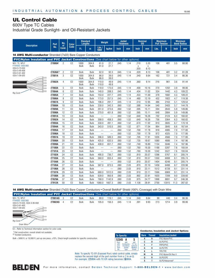
14 AWG Multi-conductor Stranded (7x22) Bare Copper Conductors
PVC/Nylon Insulation and PVC Jacket Constructions (See chart below for other options)27080A† 2 E2 1000 304.8 61.0 27.7 .045 1.14 .210 5.33 108 481 3.5 88.90
Bulk Bulk 61.0 27.7 x x.320 8.13
27636A†† 2 E2 Bulk Bulk 62.0 92.3 .045 1.14 .320 8.13 108 481 3.2 81.2827081A 3 E2 1000 304.8 86.0 39.0 .045 1.14 .340 8.64 162 721 3.4 86.36
Bulk Bulk 86.0 39.027082A 4 E2 1000 304.8 110.0 49.9 .045 1.14 .360 9.14 216 961 3.6 91.44
Bulk Bulk 110.0 49.927083A 5 E2 Bulk Bulk 118.0 175.6 .045 1.14 .400 10.16 270 1202 3.9 99.0627084A 6 E2 Bulk Bulk 140.0 208.3 .045 1.14 .434 11.02 324 1442 4.3 109.2227085A 7 E2 Bulk Bulk 153.0 227.7 .045 1.14 .433 11.00 378 1682 4.3 109.2227086A 8 E2 Bulk Bulk 173.0 257.5 .045 1.14 .480 12.19 432 1922 4.7 119.3827087A 9 E2 Bulk Bulk 196.0 291.7 .045 1.14 .510 12.95 486 2163 5.1 129.5427088A 10 E2 Bulk Bulk 230.0 342.3 .060 1.52 .588 14.94 540 2403 5.7 144.7827089A 11 E2 Bulk Bulk 251.0 373.6 .060 1.52 .595 15.11 594 2643 5.9 149.8627090A 12 E2 Bulk Bulk 270.0 401.8 .060 1.52 .595 15.11 648 2884 5.9 149.8627091A 13 E2 Bulk Bulk — — .060 1.52 .640 16.26 702 3124 6.3 160.0227092A 14 E2 Bulk Bulk 308.0 458.3 .060 1.52 .640 16.26 756 3364 6.3 160.0227093A 15 E2 Bulk Bulk 330.0 491.1 .060 1.52 .670 17.02 810 3605 6.7 170.1827094A 16 E2 Bulk Bulk 343.0 510.5 .060 1.52 .671 17.04 864 3845 6.6 167.6427095A 17 E2 Bulk Bulk — — .060 1.52 .700 17.78 918 4085 7.0 177.8027096A 18 E2 Bulk Bulk — — .060 1.52 .700 17.78 972 4325 7.0 177.8027097A 19 E2 Bulk Bulk 396.0 589.3 .060 1.52 .705 17.91 1026 4566 7.0 177.8027098A 20 E2 Bulk Bulk 425.0 632.5 .060 1.52 .735 18.67 1080 4806 7.4 187.9627099A 21 E2 Bulk Bulk 438.0 651.7 .060 1.52 .740 18.80 1134 5046 7.4 187.9627100A 22 E2 Bulk Bulk — — .060 1.52 .760 19.30 1188 5287 7.6 193.0427101A 23 E2 Bulk Bulk — — .060 1.52 .760 19.30 1242 5527 7.6 193.0427102A 24 E2 Bulk Bulk 495.0 736.7 .060 1.52 .810 20.57 1296 5767 8.1 205.7427103A 25 E2 Bulk Bulk 560.0 833.4 .060 1.52 .810 20.57 1350 6008 8.1 205.7427104A 26 E2 Bulk Bulk — — .060 1.52 .810 20.57 1404 6248 8.1 205.7427105A 27 E2 Bulk Bulk 587.0 873.5 .080 2.03 .870 22.10 1458 6488 8.7 220.9827106A 28 E2 Bulk Bulk — — .080 2.03 .910 23.11 1512 6728 9.1 231.1427107A 29 E2 Bulk Bulk 680.0 1012.0 .080 2.03 .910 23.11 1566 6969 9.1 231.1427108A 30 E2 Bulk Bulk 639.0 950.8 .080 2.03 .902 22.91 1620 7209 9.0 228.6027629A 37 E2 Bulk Bulk 768.0 1142.9 .080 2.03 .975 24.77 1998 8891 9.7 246.3827912A 50 E2 Bulk Bulk 1080.0 1607.3 .080 2.03 1.138 28.91 2700 12015 11.3 287.02
14 AWG Multi-conductor Stranded (7x22) Bare Copper Conductors • Overall Beldfoil® Shield (100% Coverage) with Drain Wire
PVC/Nylon Insulation and PVC Jacket Constructions (See chart below for other options)27081AS 3 E2 Bulk Bulk 80.0 119.1 .045 1.14 .340 8.64 99 440 3.4 86.36
27082AS 4 E2 Bulk Bulk 105.0 156.3 .045 1.14 .391 9.93 273 1214 3.9 99.06
E2 = Refer to Technical Information section for color code.† Flat construction; overall shield not available.
†† Twisted Conductors.
Bulk = 5000 ft. or 10,000 ft. put-up one piece, ±10%. Check length available for specific construction.
I N D U S T R I A L A U T O M A T I O N & P R O C E S S C O N T R O L C A B L E S 18.66
F o r m o r e i n f o r m a t i o n , c o n t a c t B e l d e n Te c h n i c a l S u p p o r t : 1 - 8 0 0 - B E L D E N - 1 • w w w . b e l d e n . c o m
UL Control Cable600V Type TC CablesIndustrial Grade Sunlight- and Oil-Resistant Jackets
Standard Lengths
Ft.
ColorCode
mm
Jacket Thickness
Inch mm
Nominal OD
Lbs. N
MaximumPull Tension
Inch
PartNo.Description
MinimumBend Radius
m
WeightNo.of
Cond. Lbs./1000′ kg/km Inch mm
12345 A SStart add addwith Conductor, “S” forcore Insulation, optionalPart Jacket BeldfoilNo. type Shield
To Specify:
Conductor, Insulation and Jacket Options
Bare Tinned Insulation/JacketA B PVC-Nylon/PVCC D XLPE/PVCE F FRPO/PVCG H XLPE/TPEK L TPE/TPEM N PVC-Nylon/Oil Res IIQ R XLPE/CPES T XLPE/Haloarrest®
Drain Wire
NEC: TC, NPLFFT4/IEEE 1202/383ICEA S-73-532ICEA S-95-658ICEA S-61-402ICEA T-29-520
NEC: TC, NPLFFT4/IEEE 1202/383ICEA S-73-532, ICEA S-95-658ICEA S-61-402, ICEA T-29-520
Note: To specify TC-ER (Exposed Run) rated control cable, simplyreplace the second digit of the part number from a 7 to an 8. For example: 27080A with TC-ER rating becomes 28080A.
Rip Cord
Rip Cord

I N D U S T R I A L A U T O M A T I O N & P R O C E S S C O N T R O L C A B L E S 18.67
18•
Indu
stria
l Cab
les
F o r m o r e i n f o r m a t i o n , c o n t a c t B e l d e n Te c h n i c a l S u p p o r t : 1 - 8 0 0 - B E L D E N - 1 • w w w . b e l d e n . c o m
UL Control Cable600V Type TC CablesIndustrial Grade Sunlight- and Oil-Resistant Jackets
12 AWG Multi-conductor Stranded (7x20) Bare Copper Conductors
PVC/Nylon Insulation and PVC Jacket Constructions (See chart below for other options)27109A† 2 E2 1000 304.8 74.0 110.0 .045 1.14 .220 5.59 172 765 3.5 88.90
Bulk Bulk 74.0 110.0 x x.350 8.89
27641A†† 2 E2 Bulk Bulk 86.0 128.0 .045 1.14 .360 9.14 172 765 3.6 91.44
27110A 3 E2 1000 304.8 110.0 163.7 .045 1.14 .374 9.50 258 1148 3.7 93.98Bulk Bulk 110.0 163.7
27111A 4 E2 1000 304.8 134.0 199.0 .045 1.14 .410 10.41 344 1531 4.1 104.14Bulk Bulk 134.0 199.0
27112A 5 E2 Bulk Bulk 165.0 245.6 .045 1.14 .450 11.43 430 1914 4.5 114.30
27113A 6 E2 Bulk Bulk 197.0 293.2 .045 1.14 .480 12.19 516 2296 4.8 121.92
27114A 7 E2 Bulk Bulk 216.0 321.5 .045 1.14 .480 12.19 602 2679 4.8 121.92
27115A 8 E2 Bulk Bulk 263.0 391.4 .060 1.52 .560 14.22 688 3062 5.6 142.24
27116A 9 E2 Bulk Bulk 297.0 442.0 .060 1.52 .600 15.24 774 3444 6.0 152.40
27117A 10 E2 Bulk Bulk 324.0 482.2 .060 1.52 .660 16.76 860 3827 6.6 167.64
27118A 11 E2 Bulk Bulk — — .060 1.52 .670 17.02 946 4210 6.7 170.18
27119A 12 E2 Bulk Bulk 378.0 562.5 .060 1.52 .670 17.02 1032 4592 6.7 170.18
27120A 13 E2 Bulk Bulk — — .060 1.52 .700 17.78 1118 4975 7.0 177.80
27121A 14 E2 Bulk Bulk — — .060 1.52 .700 17.78 1204 5358 7.0 177.80
27122A 15 E2 Bulk Bulk 468.0 696.5 .060 1.52 .740 18.80 1290 5741 7.4 187.96
27123A 16 E2 Bulk Bulk 490.0 729.2 .060 1.52 .750 19.05 1376 6123 7.5 190.50
27124A 17 E2 Bulk Bulk — — .060 1.52 .770 19.56 1462 6506 7.7 195.58
27125A 18 E2 Bulk Bulk — — .060 1.52 .770 19.56 1548 6889 7.7 195.58
27126A 19 E2 Bulk Bulk 568.0 845.3 .060 1.52 .790 20.07 1634 7271 7.9 200.66
27127A 20 E2 Bulk Bulk 640.0 952.4 .080 2.03 .870 22.10 1720 7654 8.7 220.98
27128A 21 E2 Bulk Bulk — — .080 2.03 .870 22.10 1806 8037 8.7 220.98
27129A 22 E2 Bulk Bulk — — .080 2.03 .890 22.61 1892 8419 8.9 226.06
27130A 23 E2 Bulk Bulk — — .080 2.03 .890 22.61 1978 8802 8.9 226.06
27131A 24 E2 Bulk Bulk — — .080 2.03 .940 23.88 2064 9185 9.4 238.76
27132A 25 E2 Bulk Bulk 775.0 1153.4 .080 2.03 .960 24.38 2150 9568 9.6 243.84
27133A 26 E2 Bulk Bulk — — .080 2.03 .960 24.38 2236 9950 9.6 243.84
27134A 27 E2 Bulk Bulk 828.0 1232.2 .080 2.03 .960 24.38 2322 10333 9.6 243.84
27135A 28 E2 Bulk Bulk — — .080 2.03 .990 25.15 2408 10716 9.9 251.46
27136A 29 E2 Bulk Bulk — — .080 2.03 .990 25.15 2494 11098 9.9 251.46
27137A 30 E2 Bulk Bulk 910.0 1354.3 .080 2.03 1.020 25.91 2580 11481 10.2 259.08
27630A 37 E2 Bulk Bulk 1100.0 1637.0 .080 2.03 1.090 27.69 3182 14160 10.9 276.86
27634A 50 E2 Bulk Bulk 1450.0 2157.9 .080 2.03 1.300 33.02 4300 19135 13.0 330.20E2 = Refer to Technical Information section for color code.† Flat construction; overall shield not available.
†† Twisted Conductors.
Bulk = 5000 ft. or 10,000 ft. put-up one piece, ±10%. Check length available for specific construction.
Standard Lengths
Ft.
ColorCode
mm
Jacket Thickness
Inch mm
Nominal OD
Lbs. N
MaximumPull Tension
Inch
PartNo.Description
MinimumBend Radius
m
WeightNo.of
Cond. Lbs./1000′ kg/km Inch mm
12345 A SStart add addwith Conductor, “S” forcore Insulation, optionalPart Jacket Beldfoil®No. type Shield
To Specify:
Conductor, Insulation and Jacket Options
Bare Tinned Insulation/JacketA B PVC-Nylon/PVCC D XLPE/PVCE F FRPO/PVCG H XLPE/TPEK L TPE/TPEM N PVC-Nylon/Oil Res IIQ R XLPE/CPES T XLPE/Haloarrest®
NEC: TC, NPLFFT4/IEEE 1202/383ICEA S-73-532ICEA S-95-658ICEA S-61-402ICEA T-29-520
Note: To specify TC-ER (Exposed Run) rated control cable, simplyreplace the second digit of the part number from a 7 to an 8. For example: 27080A with TC-ER rating becomes 28080A.
Rip Cord

I N D U S T R I A L A U T O M A T I O N & P R O C E S S C O N T R O L C A B L E S 18.68
F o r m o r e i n f o r m a t i o n , c o n t a c t B e l d e n Te c h n i c a l S u p p o r t : 1 - 8 0 0 - B E L D E N - 1 • w w w . b e l d e n . c o m
UL Control Cable600V Type TC CablesIndustrial Grade Sunlight- and Oil-Resistant Jackets
10 AWG Multi-conductor Stranded (7x18) Bare Copper Conductors
PVC/Nylon Insulation and PVC Jacket Constructions (See chart below for other options)27138A† 2 E2 Bulk Bulk 83.0 123.5 .045 1.14 .260 6.60 296 1317 4.2 106.68
x x.420 10.67
27643A†† 2 E2 Bulk Bulk 131.0 195.0 .045 1.14 .420 10.67 296 1317 4.2 106.68
27139A 3 E2 1000 304.8 164.0 244.0 .045 1.14 .450 11.43 444 1976 4.5 114.30Bulk Bulk 164.0 244.0
27140A 4 E2 1000 304.8 216.0 321.0 .045 1.14 .490 12.45 592 2634 4.9 124.46Bulk Bulk 216.0 321.0
27141A 5 E2 Bulk Bulk 276.0 410.7 .060 1.52 .570 14.48 740 3293 5.7 144.78
27142A 6 E2 Bulk Bulk 329.0 489.6 .060 1.52 .620 15.75 888 3952 6.2 157.48
27143A 7 E2 Bulk Bulk 361.0 537.2 .060 1.52 .620 15.75 1036 4610 6.2 157.48
27144A 8 E2 Bulk Bulk 411.0 611.7 .060 1.52 .680 17.27 1184 5269 6.8 172.72
27145A 9 E2 Bulk Bulk 465.0 692.0 .060 1.52 .720 18.29 1332 5927 7.2 182.88
27146A 10 E2 Bulk Bulk 542.0 806.6 .060 1.52 .790 20.07 1480 6586 7.9 200.66
27147A 11 E2 Bulk Bulk 582.0 866.0 .060 1.52 .790 20.07 1628 7245 7.9 200.66
27148A 12 E2 Bulk Bulk 620.0 922.7 .080 2.03 .820 20.83 1776 7903 8.2 208.28
8 AWG Multi-conductor Stranded (7x16) Bare Copper Conductors • 10 AWG Bare Copper Ground Wire
PVC/Nylon Insulation and PVC Jacket Constructions (See chart below for other options)27149A 2 ** Bulk Bulk 220.0 327.4 .060 1.52 .560 14.22 384 1709 5.6 142.24
27150A 3 ** 1000 304.8 354.0 527.0 .060 1.52 .590 14.99 576 2563 5.9 149.86Bulk Bulk 354.0 527.0
27151A 4 ** Bulk Bulk 394.0 327.4 .060 1.52 .650 16.51 768 3418 6.5 165.10
**ICEA Method 4 Color Code
6 AWG Multi-conductor Stranded (7x14) Bare Copper Conductors • 8 AWG Bare Copper Ground Wire
PVC/Nylon Insulation and PVC Jacket Constructions (See chart below for other options)27152A 2 ** Bulk Bulk 316.0 434.6 .060 1.52 .630 16.00 610 2715 6.3 160.02
27153A 3 ** 1000 304.8 477.0 710.0 .060 1.52 .670 17.02 915 4072 6.7 170.18Bulk Bulk 477.0 710.0
27154A 4 ** Bulk Bulk 519.0 759.0 .060 1.52 .730 18.54 1220 5429 7.3 185.42
**ICEA Method 4 Color Code
E2 = Refer to Technical Information section for color code.† Flat construction; overall shield not available.
†† Twisted Conductors.
Bulk = 5000 ft. or 10,000 ft. put-up one piece, ±10%. Check length available for specific construction.
Standard Lengths
Ft.
ColorCode
mm
Jacket Thickness
Inch mm
Nominal OD
Lbs. N
MaximumPull Tension
Inch
PartNo.Description
MinimumBend Radius
m
WeightNo.of
Cond. Lbs./1000′ kg/km Inch mm
12345 A SStart add addwith Conductor, “S” forcore Insulation, optionalPart Jacket Beldfoil®No. type Shield
To Specify:
Conductor, Insulation and Jacket Options
Bare Tinned Insulation/JacketA B PVC-Nylon/PVCC D XLPE/PVCE F FRPO/PVCG H XLPE/TPEK L TPE/TPEM N PVC-Nylon/Oil Res IIQ R XLPE/CPES T XLPE/Haloarrest®
NEC: TC, NPLFFT4/IEEE 1202/383ICEA S-73-532ICEA S-95-658ICEA S-61-402ICEA T-29-520
NEC: TC, NPLFFT4/IEEE 1202/383ICEA S-73-532ICEA S-95-658ICEA S-61-402ICEA T-29-520
NEC: TC, NPLFFT4/IEEE 1202/383ICEA S-73-532ICEA S-95-658ICEA S-61-402ICEA T-29-520
Note: To specify TC-ER (Exposed Run) rated control cable, simplyreplace the second digit of the part number from a 7 to an 8. For example: 27080A with TC-ER rating becomes 28080A.
Rip Cord
Rip Cord
Rip Cord

I N D U S T R I A L A U T O M A T I O N & P R O C E S S C O N T R O L C A B L E S 18.69
18•
Indu
stria
l Cab
les
F o r m o r e i n f o r m a t i o n , c o n t a c t B e l d e n Te c h n i c a l S u p p o r t : 1 - 8 0 0 - B E L D E N - 1 • w w w . b e l d e n . c o m
UL Control Cable600V Type TC CablesIndustrial Grade Sunlight- and Oil-Resistant Jackets
4 AWG Multi-conductor Stranded (7x12) Bare Copper Conductors • 8 AWG Bare Copper Ground Wire
PVC/Nylon Insulation and PVC Jacket Constructions (See chart below for other options)27155A 2 ** Bulk Bulk 455.0 677.1 .060 1.52 .770 19.56 970 4317 7.7 195.58
27156A 3 ** Bulk Bulk 630.0 937.6 .080 2.03 .820 20.83 1455 6475 8.2 208.28
27157A 4 ** Bulk Bulk 850.0 1265.0 .080 2.03 .950 24.13 1940 8633 9.5 241.30
**ICEA Method 4 Color Code
2 AWG Multi-conductor Stranded (7x10) Bare Copper Conductors • 6 AWG Bare Copper Ground Wire
PVC/Nylon Insulation and PVC Jacket Constructions (See chart below for other options)27158A 2 ** Bulk Bulk 716.0 1065.6 .080 2.03 .970 24.64 1544 6871 9.7 246.38
27159A 3 ** Bulk Bulk 960.0 1428.7 .080 2.03 .990 25.15 2316 10306 9.9 251.46
27160A 4 ** Bulk Bulk 1213.0 1805.2 .080 2.03 1.090 27.69 3088 13742 10.9 276.86
**ICEA Method 4 Color Code
1 AWG Multi-conductor Stranded (19x14) Bare Copper Conductors • 6 AWG Bare Copper Ground Wire
PVC/Nylon Insulation and PVC Jacket Constructions (See chart below for other options)27161A 3 ** Bulk Bulk — — .080 2.03 1.120 28.45 2919 12990 11.2 284.48
**ICEA Method 4 Color Code
Bulk = 5000 ft. or 10,000 ft. put-up one piece, ±10%. Check length available for specific construction.
Standard Lengths
Ft.
ColorCode
mm
Jacket Thickness
Inch mm
Nominal OD
Lbs. N
MaximumPull Tension
Inch
PartNo.Description
MinimumBend Radius
m
WeightNo.of
Cond. Lbs./1000′ kg/km Inch mm
12345 A SStart add addwith Conductor, “S” forcore Insulation, optionalPart Jacket Beldfoil®No. type Shield
To Specify:
Conductor, Insulation and Jacket Options
Bare Tinned Insulation/JacketA B PVC-Nylon/PVCC D XLPE/PVCE F FRPO/PVCG H XLPE/TPEK L TPE/TPEM N PVC-Nylon/Oil Res IIQ R XLPE/CPES T XLPE/Haloarrest®
NEC: TC, NPLFFT4/IEEE 1202/383ICEA S-73-532ICEA S-95-658ICEA S-61-402ICEA T-29-520
NEC: TC, NPLFFT4/IEEE 1202/383ICEA S-73-532ICEA S-95-658ICEA S-61-402ICEA T-29-520
NEC: TC, NPLFFT4/IEEE 1202/383ICEA S-73-532ICEA S-95-658ICEA S-61-402ICEA T-29-520
Note: To specify TC-ER (Exposed Run) rated control cable, simplyreplace the second digit of the part number from a 7 to an 8. For example: 27080A with TC-ER rating becomes 28080A.
Rip Cord
Rip Cord
Rip Cord
I N D U S T R I A L A U T O M A T I O N & P R O C E S S C O N T R O L C A B L E S 18.70
F o r m o r e i n f o r m a t i o n , c o n t a c t B e l d e n Te c h n i c a l S u p p o r t : 1 - 8 0 0 - B E L D E N - 1 • w w w . b e l d e n . c o m
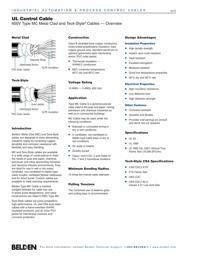
UL Control Cable600V Type MC Metal Clad and Teck-Style® Cables — Overview
Introduction
Belden® Metal Clad (MC) and Teck-Stylecables are designed to meet demandingindustrial needs by combining rugged durability and corrosion resistance with flexibility and easy handling.
MC and Teck-Style cables are available in a wide range of constructions to meetthe needs of pulp and paper, chemical,petroleum and other demanding industrialand resource industry environments. Theyare ideal for use in wet or dry areas; ventilated, non-ventilated or ladder-typecable troughs; ventilated flexible cableways;and for direct burial. Custom cables areavailable to meet exacting requirements.
Belden Type MC Cable is marked sunlight-resistant for cable tray use in direct burial designations, and cable constructions are listed to NEC Type MC.
Teck-Style cables are price-competitive,high-performance, UL and CSA dual-rated cables with a flame-retardant XHHW insulated conductor and an inner PVC jacket for mechanical moisture and corrosion protection.
Construction
Class B stranded bare copper conductors,cross-linked polyethylene insulation, barecopper ground wire, standard aluminum oroptional galvanized steel interlockingarmor, PVC outer jacket.
Thermoset insulation — XHHW-2 conductors
NEC conductor temperature90°C dry and 90°C wet
Voltage Rating
14 AWG — 2 AWG: 600 Volt
Application
Type MC Cable is a general-purpose cable used in the pulp and paper, mining,petroleum and chemical industries as well as in commercial buildings.
MC Cable may be used under the following conditions:
Exposed or concealed wiring in dry or wet conditions
In ventilated, non-ventilated or ladder-type cable trays in dry or wet conditions
On walls or beams
Directly buried
Class I and II Div. 2 and Class III Div. 1 and 2 hazardous locations
Minimum Bending Radius
12 times the overall cable diameter
Pulling Tensions
The combined use of Kellems grips and pulling eyes is recommended.
Design Advantages
Insulation Properties
High tensile strength
Impact- and crush-resistant
Heat-resistant
Excellent elongation
Moisture-resistant
Good low temperature properties
90°C dry and 90°C wet
Electrical Properties
High insulation resistance
Low dielectric loss
High dielectric strength
Other Features
Corrosion-resistant
Versatile and flexible
Provides cost savings as conduit and ducts are not required
Specifications
UL 44
UL 1569
UL 1685 (UL 1581) Vertical Tray Flame Test (70,000 BTU/hr)
Tech-Style CSA Specifications
CSA C22.2 #131
FT4 Flame Test
HAZ LOC
CSA C22.2 #0.3 Clause 4.31 Low Acid Gas
PVC Outer Jacket
Interlocked Armor
Polyester Wrap
XLPE Insulation
PVC Outer Jacket
Interlocked Armor
Inner Jacket
XLPE Insulation
Metal Clad
Teck-Style

I N D U S T R I A L A U T O M A T I O N & P R O C E S S C O N T R O L C A B L E S 18.71
18•
Indu
stria
l Cab
les
F o r m o r e i n f o r m a t i o n , c o n t a c t B e l d e n Te c h n i c a l S u p p o r t : 1 - 8 0 0 - B E L D E N - 1 • w w w . b e l d e n . c o m
UL Control Cable600V Type MC Metal Clad CablesIndustrial Grade Sunlight- and Oil-Resistant Jackets
Part Number
Steel Armor
No.of
Cond.AluminumArmor
Outer Jacket Thickness
InsulationThickness
mm Inch
Armor OD
Inchmm mm Inch mm
Nominal OD
InchDescription
MinimumBend Radius
Inch mm
14 AWG Stranded (7x22) Bare Copper Conductors • 14 AWG Bare Copper Ground Wire
Aluminum or Steel Interlocked Armor • Cross-linked Polyethylene Insulation • PVC JacketNEC: MC 27243 28243 2 .030 .76 .050 1.27 .48 12.19 .58 14.73 7.3 185.42
27244 28244 3 .030 .76 .050 1.27 .50 12.70 .61 15.49 7.6 193.04
27245 28245 4 .030 .76 .050 1.27 .54 13.72 .64 16.26 7.9 200.66
27246 28246 5 .030 .76 .050 1.27 .57 14.48 .68 17.27 8.4 213.36
27247 28247 6 .030 .76 .050 1.27 .62 15.75 .72 18.29 8.9 226.06
27248 28248 7 .030 .76 .050 1.27 .62 15.75 .72 18.29 8.9 226.06
27269 28269 8 .030 .76 .050 1.27 .69 17.53 .80 20.32 9.4 238.76
27535 28535 9 .030 .76 .050 1.27 .70 17.78 .80 20.32 10.0 254.00
27249 28249 10 .030 .76 .050 1.27 .75 19.05 .85 21.59 10.5 266.70
27250 28250 12 .030 .76 .050 1.27 .77 19.56 .87 22.10 10.8 274.32
27251 28251 15 .030 .76 .050 1.27 .87 22.10 .98 24.89 11.6 294.64
27969 28969 19 .030 .76 .050 1.27 1.00 25.40 1.11 28.19 12.1 307.34
27252 28252 20 .030 .76 .050 1.27 1.03 26.16 1.14 28.96 13.3 337.82
27270 28270 25 .030 .76 .050 1.27 1.10 27.94 1.21 30.73 14.4 365.76
27253 28253 30 .030 .76 .050 1.27 1.18 29.97 1.29 32.77 15.1 383.54
27292 28292 37 .030 .76 .050 1.27 1.14 28.96 1.24 31.50 16.1 408.94
27433 28433 40 .030 .76 .050 1.27 1.28 32.51 1.40 35.56 16.7 424.18
27434 28434 50 .030 .76 .050 1.27 1.40 35.56 1.52 38.61 18.4 467.36
12 AWG Stranded (7x20) Bare Copper Conductors • 12 AWG Bare Copper Ground Wire
Aluminum or Steel Interlocked Armor • Cross-linked Polyethylene Insulation • PVC JacketNEC: MC 27254 28254 2 .030 .76 .050 1.27 .52 13.21 .62 15.75 7.8 198.12
27255 28255 3 .030 .76 .050 1.27 .54 13.72 .64 16.26 8.0 203.20
27256 28256 4 .030 .76 .050 1.27 .58 14.73 .68 17.22 8.5 215.90
27271 28271 5 .030 .76 .050 1.27 .62 15.75 .72 18.29 9.1 231.14
27272 28272 6 .030 .76 .050 1.27 .67 17.02 .77 19.56 9.6 243.84
27273 28273 7 .030 .76 .050 1.27 .67 17.02 .77 19.56 9.6 243.84
27274 28274 8 .030 .76 .050 1.27 .77 19.56 .88 22.35 10.2 259.08
27538 28538 9 .030 .76 .050 1.27 .76 19.30 .86 21.84 10.8 274.32
27275 28275 10 .030 .76 .050 1.27 .80 20.32 .91 23.11 11.5 292.10
27276 28276 12 .030 .76 .050 1.27 .84 21.34 .94 23.88 11.7 297.18
27277 28277 15 .030 .76 .050 1.27 .94 23.88 1.05 26.67 13.4 340.36
27539 28539 19 .030 .76 .055 1.40 1.05 26.67 1.16 29.46 14.0 355.60
27278 28278 20 .030 .76 .055 1.40 1.16 29.46 1.27 32.26 14.6 370.84
27279 28279 25 .030 .76 .055 1.40 1.26 32.00 1.37 34.80 15.8 401.32
27280 28280 30 .030 .76 .055 1.40 1.29 32.77 1.40 35.56 16.8 426.72
27540 28540 37 .030 .76 .055 1.40 1.44 36.58 1.55 39.37 17.8 452.12
27432 28432 40 .030 .76 .055 1.40 1.50 38.10 1.63 41.40 18.4 467.36Color Code: Use ICEA Table E2 with printed numbers.
Non-stocked items. Check length available for specific construction. Minimum order may apply.
UL Control Cable600V Type MC Metal Clad CablesIndustrial Grade Sunlight- and Oil-Resistant Jackets
I N D U S T R I A L A U T O M A T I O N & P R O C E S S C O N T R O L C A B L E S 18.72
F o r m o r e i n f o r m a t i o n , c o n t a c t B e l d e n Te c h n i c a l S u p p o r t : 1 - 8 0 0 - B E L D E N - 1 • w w w . b e l d e n . c o m
Part Number
Steel Armor
No.of
Cond.AluminumArmor
Outer Jacket Thickness
InsulationThickness
mm Inch
Armor OD
Inchmm mm Inch mm
Nominal OD
InchDescription
MinimumBend Radius
Inch mm
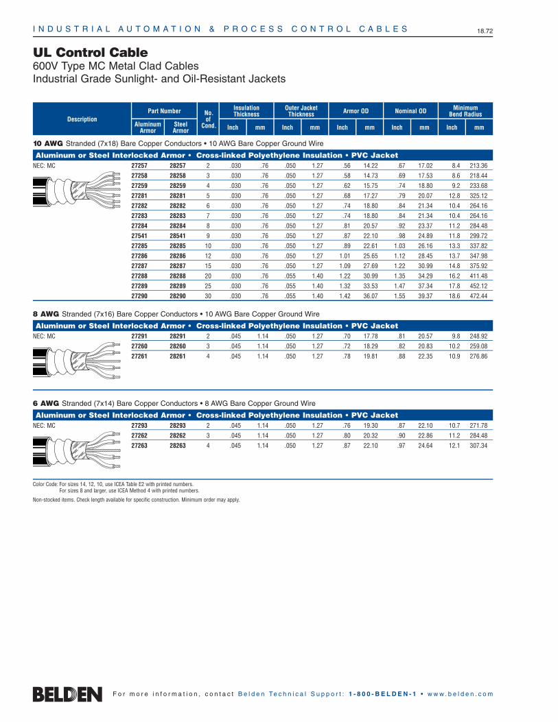
10 AWG Stranded (7x18) Bare Copper Conductors • 10 AWG Bare Copper Ground Wire
Aluminum or Steel Interlocked Armor • Cross-linked Polyethylene Insulation • PVC JacketNEC: MC 27257 28257 2 .030 .76 .050 1.27 .56 14.22 .67 17.02 8.4 213.36
27258 28258 3 .030 .76 .050 1.27 .58 14.73 .69 17.53 8.6 218.44
27259 28259 4 .030 .76 .050 1.27 .62 15.75 .74 18.80 9.2 233.68
27281 28281 5 .030 .76 .050 1.27 .68 17.27 .79 20.07 12.8 325.12
27282 28282 6 .030 .76 .050 1.27 .74 18.80 .84 21.34 10.4 264.16
27283 28283 7 .030 .76 .050 1.27 .74 18.80 .84 21.34 10.4 264.16
27284 28284 8 .030 .76 .050 1.27 .81 20.57 .92 23.37 11.2 284.48
27541 28541 9 .030 .76 .050 1.27 .87 22.10 .98 24.89 11.8 299.72
27285 28285 10 .030 .76 .050 1.27 .89 22.61 1.03 26.16 13.3 337.82
27286 28286 12 .030 .76 .050 1.27 1.01 25.65 1.12 28.45 13.7 347.98
27287 28287 15 .030 .76 .050 1.27 1.09 27.69 1.22 30.99 14.8 375.92
27288 28288 20 .030 .76 .055 1.40 1.22 30.99 1.35 34.29 16.2 411.48
27289 28289 25 .030 .76 .055 1.40 1.32 33.53 1.47 37.34 17.8 452.12
27290 28290 30 .030 .76 .055 1.40 1.42 36.07 1.55 39.37 18.6 472.44
8 AWG Stranded (7x16) Bare Copper Conductors • 10 AWG Bare Copper Ground Wire
Aluminum or Steel Interlocked Armor • Cross-linked Polyethylene Insulation • PVC JacketNEC: MC 27291 28291 2 .045 1.14 .050 1.27 .70 17.78 .81 20.57 9.8 248.92
27260 28260 3 .045 1.14 .050 1.27 .72 18.29 .82 20.83 10.2 259.08
27261 28261 4 .045 1.14 .050 1.27 .78 19.81 .88 22.35 10.9 276.86
6 AWG Stranded (7x14) Bare Copper Conductors • 8 AWG Bare Copper Ground Wire
Aluminum or Steel Interlocked Armor • Cross-linked Polyethylene Insulation • PVC JacketNEC: MC 27293 28293 2 .045 1.14 .050 1.27 .76 19.30 .87 22.10 10.7 271.78
27262 28262 3 .045 1.14 .050 1.27 .80 20.32 .90 22.86 11.2 284.48
27263 28263 4 .045 1.14 .050 1.27 .87 22.10 .97 24.64 12.1 307.34
Color Code: For sizes 14, 12, 10, use ICEA Table E2 with printed numbers.For sizes 8 and larger, use ICEA Method 4 with printed numbers.
Non-stocked items. Check length available for specific construction. Minimum order may apply.

I N D U S T R I A L A U T O M A T I O N & P R O C E S S C O N T R O L C A B L E S 18.73
18•
Indu
stria
l Cab
les
F o r m o r e i n f o r m a t i o n , c o n t a c t B e l d e n Te c h n i c a l S u p p o r t : 1 - 8 0 0 - B E L D E N - 1 • w w w . b e l d e n . c o m
UL Control Cable600V Type MC Metal Clad CablesIndustrial Grade Sunlight- and Oil-Resistant Jackets
Part Number
Steel Armor
No.of
Cond.AluminumArmor
Outer Jacket Thickness
InsulationThickness
mm Inch
Armor OD
Inchmm mm Inch mm
Nominal OD
InchDescription
MinimumBend Radius
Inch mm
4 AWG Stranded (7x12) Bare Copper Conductors • 8 AWG Bare Copper Ground Wire
Aluminum or Steel Interlocked Armor • Cross-linked Polyethylene Insulation • PVC JacketNEC: MC 27264 28264 3 .045 1.14 .050 1.27 .90 22.86 1.00 25.40 13.1 332.74
27265 28265 4 .045 1.14 .050 1.27 1.97 50.04 1.08 27.43 14.2 360.68
2 AWG Stranded (7x10) Bare Copper Conductors • 6 AWG Bare Copper Ground Wire
Aluminum or Steel Interlocked Armor • Cross-linked Polyethylene Insulation • PVC JacketNEC: MC 27267 28267 3 .045 1.14 .050 1.27 1.02 25.91 1.13 28.70 14.7 373.38
27268 28268 4 .045 1.14 .050 1.27 1.11 28.19 1.22 30.99 16.0 406.40
Composite 14 AWG (7x22) and 12 AWG (7x20) Stranded Bare Copper Conductors • 12 AWG Bare Copper Ground Wire
Aluminum or Steel Interlocked Armor • Cross-linked Polyethylene Insulation • PVC JacketNEC: MC 27428 28428 3c/14 .030 .76 .050 1.27 .70 17.78 .81 20.57 9.7 246.38
3c/12 .030 .76
Composite 14 AWG (7x22) and 10 AWG (7x18) Stranded Bare Copper Conductors • 10 AWG Bare Copper Ground Wire
Aluminum or Steel Interlocked Armor • Cross-linked Polyethylene Insulation • PVC JacketNEC: MC 27429 28429 3c/14 .030 .76 .050 1.27 .74 18.80 .85 21.59 10.2 259.08
3c/10 .030 .76
Composite 14 AWG (7x22) and 8 AWG (7x16) Stranded Bare Copper Conductors • 10 AWG Bare Copper Ground Wire
Aluminum or Steel Interlocked Armor • Cross-linked Polyethylene Insulation • PVC JacketNEC: MC 27430 28430 3c/14 .030 .76 .050 1.27 .83 21.08 .94 23.88 11.2 284.48
3c/8 .045 1.14
Composite 14 AWG (7x22) and 6 AWG (7x14) Stranded Bare Copper Conductors • 8 AWG Bare Copper Ground Wire
Aluminum or Steel Interlocked Armor • Cross-linked Polyethylene Insulation • PVC JacketNEC: MC 27431 28431 3c/14 .030 .76 .050 1.27 .89 22.61 1.01 25.65 12.0 304.80
3c/6 .045 1.14
Color Code: For sizes 14, 12, 10, use ICEA Table E2 with printed numbers.For sizes 8 and larger, use ICEA Method 4 with printed numbers.
Non-stocked items. Check length available for specific construction. Minimum order may apply.

I N D U S T R I A L A U T O M A T I O N & P R O C E S S C O N T R O L C A B L E S 18.74
F o r m o r e i n f o r m a t i o n , c o n t a c t B e l d e n Te c h n i c a l S u p p o r t : 1 - 8 0 0 - B E L D E N - 1 • w w w . b e l d e n . c o m
UL Control Cable600V Teck-Style® CablesDual-Rated Type MC/Teck 90
Inner Jacket OD
mm Inch
Armor ODPart Number
Steel Armor
AluminumArmor
InsulationThicknessNo.
ofCond.
NominalOD
Inch
Maximum Pull Tension
mm mm Inch mmInchDescription
MinimumBend Radius
Inch mmLbs. N
14 AWG Stranded (7x22) Bare Copper Conductors • 14 AWG Bare Copper Ground Wire
Aluminum or Steel Armor • Cross-linked Polyethylene Insulation • PVC Inner Jacket • PVC Outer JacketNEC: MC 27840 28840 2 .030 .76 .37 9.40 .56 14.22 .67 17.02 66 294 8.0 203
27841 28841 3 .030 .76 .39 9.91 .58 14.73 .69 17.53 98 436 8.3 211
27842 28842 4 .030 .76 .43 10.92 .62 15.75 .73 18.54 131 583 8.7 221
27843 28843 5 .030 .76 .47 11.94 .66 16.76 .77 19.56 164 730 9.2 234
27844 28844 6 .030 .76 .51 12.95 .70 17.78 .81 20.57 191 850 9.7 246
27845 28845 7 .030 .76 .51 12.95 .70 17.78 .81 20.57 225 1001 9.7 246
27846 28846 8 .030 .76 .58 14.73 .77 19.56 .88 22.35 260 1157 10.5 267
27847 28847 10 .030 .76 .67 17.02 .93 23.62 1.04 26.42 321 1428 12.5 318
27848 28848 12 .030 .76 .69 17.53 .95 24.13 1.06 26.92 388 1726 10.9 277
27849 28849 15 .030 .76 .77 19.56 1.03 26.16 1.14 28.96 481 2140 13.7 348
27850 28850 20 .030 .76 .86 21.84 1.12 28.45 1.23 31.24 649 2887 15.3 389
27851 28851 25 .030 .76 .92 23.37 1.18 29.97 1.30 33.02 810 3603 16.3 414
CSA C22.2 #13127852 28852 30 .030 .76 .98 24.89 1.24 31.50 1.36 34.54 975 4337 17.0 432
FT4 Flame Test, HAZ LOC27885 28885 40 .030 .76 1.09 27.69 1.35 34.29 1.47 37.34 1301 5787 18.5 470
CSA C22.2 #0.3 Clause 4.31 Low Acid Gas 27886 28886 50 .030 .76 1.19 30.23 1.45 36.83 1.57 39.88 1630 7251 19.8 503
12 AWG Stranded (7x20) Bare Copper Conductors • 12 AWG Bare Copper Ground Wire
Aluminum or Steel Armor • Cross-linked Polyethylene Insulation • PVC Inner Jacket • PVC Outer JacketNEC: MC 27853 28853 2 .030 .76 .41 10.41 .60 15.24 .71 18.03 104 463 8.5 216
27854 28854 3 .030 .76 .43 10.92 .62 15.75 .73 18.54 156 694 8.8 224
27855 28855 4 .030 .76 .47 11.94 .66 16.76 .77 19.56 207 921 9.2 234
27856 28856 5 .030 .76 .52 13.21 .71 18.03 .82 20.83 260 1157 9.8 249
27857 28857 6 .030 .76 .59 14.99 .78 19.81 .89 22.61 310 1379 10.7 272
27858 28858 7 .030 .76 .59 14.99 .78 19.81 .89 22.61 361 1606 10.7 272
27859 28859 8 .030 .76 .64 16.26 .83 21.08 .94 23.88 415 1846 11.3 287
27860 28860 10 .030 .76 .75 19.05 1.01 25.65 1.12 28.45 520 2313 13.4 340
27861 28861 12 .030 .76 .77 19.56 1.03 26.16 1.14 28.96 619 2753 13.7 348
27862 28862 15 .030 .76 .87 22.10 1.13 28.70 1.25 31.75 718 3194 15.0 381
27863 28863 20 .030 .76 .96 24.38 1.22 30.99 1.33 33.78 1040 4626 15.9 404
CSA C22.2 #13127864 28864 25 .030 .76 1.04 26.42 1.30 33.02 1.42 36.07 1301 5787 17.0 432
FT4 Flame Test, HAZ LOC27865 28865 30 .030 .76 1.15 29.21 1.41 35.81 1.53 38.86 1560 6939 18.3 465
CSA C22.2 #0.3 Clause 4.31 Low Acid Gas 27887 28887 40 .030 .76 1.20 30.48 1.54 39.12 1.67 42.42 2020 8985 20.0 508Color Code: Use ICEA Table E2 with printed numbers.
Non-stocked items. Check length available for specific construction. Minimum order may apply.

I N D U S T R I A L A U T O M A T I O N & P R O C E S S C O N T R O L C A B L E S 18.75
18•
Indu
stria
l Cab
les
F o r m o r e i n f o r m a t i o n , c o n t a c t B e l d e n Te c h n i c a l S u p p o r t : 1 - 8 0 0 - B E L D E N - 1 • w w w . b e l d e n . c o m
UL Control Cable600V Teck-Style® CablesDual-Rated Type MC/Teck 90
10 AWG Stranded (7x18) Bare Copper Conductors • 10 AWG Bare Copper Ground Wire
Aluminum or Steel Armor • Cross-linked Polyethylene Insulation • PVC Inner Jacket • PVC Outer JacketNEC: MC 27866 28866 2 .030 .76 .46 11.68 .65 16.51 .74 18.80 166 738 9.1 231
27867 28867 3 .030 .76 .48 12.19 .67 17.02 .77 19.56 249 1108 9.4 239
27868 28868 4 .030 .76 .56 14.22 .75 19.05 .84 21.34 330 1468 10.3 262
27869 28869 5 .030 .76 .67 17.02 .86 21.84 .96 24.38 415 1846 11.6 295
27870 28870 6 .030 .76 .67 17.02 .86 21.84 .96 24.38 491 2184 11.6 295
27877 28877 7 .030 .76 .70 17.78 .90 22.86 1.00 25.40 560 2491 12.1 307
27878 28878 8 .030 .76 .75 19.05 .95 24.13 1.05 26.67 640 2847 12.7 323
27879 28879 10 .030 .76 .78 19.81 1.04 26.42 1.15 29.21 801 3563 13.8 351
27880 28880 12 .030 .76 .89 22.61 1.15 29.21 1.26 32.00 960 4270 15.1 384
27881 28881 15 .030 .76 .93 23.62 1.19 30.23 1.30 33.02 1195 5316 15.6 396
CSA C22.2 #13127882 28882 20 .030 .76 1.06 26.92 1.32 33.53 1.44 36.58 1600 7117 17.3 439
FT4 Flame Test, HAZ LOC27883 28883 25 .030 .76 1.12 28.45 1.44 36.58 1.58 40.13 1990 8852 19.0 483
CSA C22.2 #0.3 Clause 4.31 Low Acid Gas 27884 28884 30 .030 .76 1.28 32.51 1.54 39.12 1.67 42.42 2355 10476 20.0 508
8 AWG Stranded (7x16) Bare Copper Conductors • 10 AWG Bare Copper Ground Wire
Aluminum or Steel Armor • Cross-linked Polyethylene Insulation • PVC Inner Jacket • PVC Outer JacketNEC: MC 27871 28871 2 .045 1.14 .59 14.99 .78 19.81 .89 22.61 264 1174 10.7 272
27872 28872 3 .045 1.14 .62 15.75 .81 20.57 .91 23.11 396 1762 10.9 277
27873 28873 4 .045 1.14 .68 17.27 .94 23.88 1.05 26.67 528 2349 12.6 320
CSA C22.2 #131, FT4 Flame Test, HAZ LOC, CSA C22.2 #0.3 Clause 4.31 Low Acid Gas
6 AWG Stranded (7x14) Bare Copper Conductors • 8 AWG Bare Copper Ground Wire
Aluminum or Steel Armor • Cross-linked Polyethylene Insulation • PVC Inner Jacket • PVC Outer JacketNEC: MC 27874 28874 2 .060 1.52 .71 18.03 .97 24.64 1.08 27.43 420 1868 13.0 330
27875 28875 3 .060 1.52 .76 19.30 1.02 25.91 1.13 28.70 630 2802 13.5 343
27876 28876 4 .060 1.52 .88 22.35 1.14 28.96 1.25 31.75 840 3737 15.0 381
CSA C22.2 #131, FT4 Flame Test, HAZ LOC, CSA C22.2 #0.3 Clause 4.31 Low Acid Gas
4 AWG Stranded (7x12) Bare Copper Conductors • 8 AWG Bare Copper Ground Wire
Aluminum or Steel Armor • Cross-linked Polyethylene Insulation • PVC Inner Jacket • PVC Outer JacketNEC: MC 27894 28894 3 .060 1.52 .91 23.11 1.17 29.72 1.29 32.77 1002 4457 15.5 394
27895 28895 4 .060 1.52 .99 25.15 1.25 31.75 1.37 34.80 1335 5938 16.4 417
CSA C22.2 #131, FT4 Flame Test, HAZ LOC, CSA C22.2 #0.3 Clause 4.31 Low Acid Gas
3 AWG Stranded (7x11) Bare Copper Conductors • 6 AWG Bare Copper Ground Wire
Aluminum or Steel Armor • Cross-linked Polyethylene Insulation • PVC Inner Jacket • PVC Outer JacketNEC: MC 27896 28896 3 .060 1.52 .96 24.38 1.22 30.99 1.33 33.78 1263 5618 16.0 406
CSA C22.2 #131, FT4 Flame Test, HAZ LOC, CSA C22.2 #0.3 Clause 4.31 Low Acid Gas
Color Code: For sizes 14, 12, 10, use ICEA Table E2 with printed numbers.For sizes 8 and larger, use ICEA Method 4 with printed numbers.
Non-stocked items. Check length available for specific construction. Minimum order may apply.
Inner Jacket OD
mm Inch
Armor ODPart Number
Steel Armor
AluminumArmor
InsulationThicknessNo.
ofCond.
NominalOD
Inch
Maximum Pull Tension
mm mm Inch mmInchDescription
MinimumBend Radius
Inch mmLbs. N

I N D U S T R I A L A U T O M A T I O N & P R O C E S S C O N T R O L C A B L E S 18.76
F o r m o r e i n f o r m a t i o n , c o n t a c t B e l d e n Te c h n i c a l S u p p o r t : 1 - 8 0 0 - B E L D E N - 1 • w w w . b e l d e n . c o m
UL Control Cable600V Teck-Style® CablesDual-Rated Type MC/Teck 90
2 AWG Stranded (7x10) Bare Copper Conductors • 6 AWG Bare Copper Ground Wire
Aluminum or Steel Armor • Cross-linked Polyethylene Insulation • PVC Inner Jacket • PVC Outer JacketNEC: MC 27888 28888 3 .060 1.52 1.08 27.43 1.28 32.51 1.40 35.56 1593 7086 16.8 427
27889 28889 4 .060 1.52 1.12 28.45 1.38 35.05 1.50 38.10 2124 9448 18.0 457
CSA C22.2 #131, FT4 Flame Test, HAZ LOC, CSA C22.2 #0.3 Clause 4.31 Low Acid Gas
Composite 14 AWG (7x22) and 12 AWG (7x20) Bare Copper Conductors • 12 AWG Bare Copper Ground Wire
Aluminum or Steel Armor • Cross-linked Polyethylene Insulation • PVC Inner Jacket • PVC Outer JacketNEC: MC 27890 28890 3c/14 .030 .76 .56 14.22 .75 19.05 .86 21.84 202 899 10.3 262
3c/12 .030 .76
CSA C22.2 #131, FT4 Flame Test, HAZ LOC, CSA C22.2 #0.3 Clause 4.31 Low Acid Gas
Composite 14 AWG (7x22) and 10 AWG (7x18) Bare Copper Conductors • 10 AWG Bare Copper Ground Wire
Aluminum or Steel Armor • Cross-linked Polyethylene Insulation • PVC Inner Jacket • PVC Outer JacketNEC: MC 27891 28891 3c/14 .030 .76 .61 15.49 .80 20.32 .91 23.11 305 1357 10.9 277
3c/10 .030 .76
CSA C22.2 #131, FT4 Flame Test, HAZ LOC, CSA C22.2 #0.3 Clause 4.31 Low Acid Gas
Composite 14 AWG (7x22) and 8 AWG (7x16) Bare Copper Conductors • 10 AWG Bare Copper Ground Wire
Aluminum or Steel Armor • Cross-linked Polyethylene Insulation • PVC Inner Jacket • PVC Outer JacketNEC: MC 27892 28892 3c/14 .045 1.14 .70 17.78 .96 24.38 1.07 27.18 435 1935 12.8 325
3c/8 .030 .76
CSA C22.2 #131, FT4 Flame Test, HAZ LOC, CSA C22.2 #0.3 Clause 4.31 Low Acid Gas
Composite 14 AWG (7x22) and 6 AWG (7x14) Bare Copper Conductors • 8 AWG Bare Copper Ground Wire
Aluminum or Steel Armor • Cross-linked Polyethylene Insulation • PVC Inner Jacket • PVC Outer JacketNEC: MC 27893 28893 3c/14 .060 1.52 .90 22.86 1.15 29.21 1.26 32.00 655 2914 15.1 384
3c/6 .030 .76
CSA C22.2 #131, FT4 Flame Test, HAZ LOC, CSA C22.2 #0.3 Clause 4.31 Low Acid Gas
Color Code: For sizes 14, 12, 10, use ICEA Table E2 with printed numbers.For sizes 8 and larger, use ICEA Method 4 with printed numbers.
Non-stocked items. Check length available for specific construction. Minimum order may apply.
Inner Jacket OD
mm Inch
Armor ODPart Number
Steel Armor
AluminumArmor
InsulationThicknessNo.
ofCond.
NominalOD
Inch
Maximum Pull Tension
mm mm Inch mmInchDescription
MinimumBend Radius
Inch mmLbs. N

I N D U S T R I A L A U T O M A T I O N & P R O C E S S C O N T R O L C A B L E S 18.77
18•
Indu
stria
l Cab
les
F o r m o r e i n f o r m a t i o n , c o n t a c t B e l d e n Te c h n i c a l S u p p o r t : 1 - 8 0 0 - B E L D E N - 1 • w w w . b e l d e n . c o m
CSA Instrumentation & Thermocouple Tray Cable300V TC/CIC Paired and Triad Constructions
20 AWG1 22000 21100 21114 21128 211422 22001 21101 21115 21129 211434 22002 21102 21116 21130 211446 22003 21103 21117 21131 211458 22004 21104 21118 21132 2114610 22005 21105 21119 21133 2114712 22006 21106 21120 21134 2114816 22007 21107 21121 21135 2114920 22008 21108 21122 21136 2115024 22009 21109 21123 21137 2115130 22010 21110 21124 21138 2115236 22011 21111 21125 21139 2115340 22012 21112 21126 21140 2115450 22013 21113 21127 21141 21155
18 AWG1 22027 21156 21170 21184 211982 22028 21157 21171 21185 211994 22029 21158 21172 21186 212006 22030 21159 21173 21187 212018 22031 21160 21174 21188 2120210 22032 21161 21175 21189 2120312 22033 21162 21176 21190 2120416 22034 21163 21177 21191 2120520 22035 21164 21178 21192 2120624 22036 21165 21179 21193 2120730 22037 21166 21180 21194 2120836 22038 21167 21181 21195 2120940 22039 21168 21182 21196 2121050 22040 21169 21183 21197 21211
16 AWG1 22054 21212 21226 21240 212542 22055 21213 21227 21241 212554 22056 21214 21228 21242 212566 22057 21215 21229 21243 212578 22058 21216 21230 21244 2125810 22059 21217 21231 21245 2125912 22060 21218 21232 21246 2126016 22061 21219 21233 21247 2126120 22062 21220 21234 21248 2126224 22063 21221 21235 21249 2126330 22064 21222 21236 21250 2126436 22065 21223 21237 21251 2126540 22066 21224 21238 21252 2126650 22067 21225 21239 21253 21267
Part Numbers
7 StrandCopper
Solid EX Chromel/Constantan
SolidJX Iron/
Constantan
Solid KX Chromel/
Alumel
Solid TX Copper/Constantan
No.of
Pairs
Part Numbers
20 AWG(7 Strand)
18 AWG(7 Strand)
16 AWG(7 Strand)
No.of
Triads
1 22014 22041 220682 22015 22042 220694 22016 22043 220706 22017 22044 220718 22018 22045 2207210 22019 22046 2207312 22020 22047 2207416 22021 22048 2207520 22022 22049 2207624 22023 22050 2207730 22024 22051 2207836 22025 22052 22079
Triad Constructions, Copper Conductor
Cable Specifications
CSA C22.2 #239 Control and Instrumentation
CSA C22.2 #230 Type TC
CSA FT4 70,000 BTU Flame Test
PVC Insulation 90°C Dry & 75°C Wet
XLPE Insulation Optional 90°C Dry and Wet
-40°C Cold Bend, -25°C Cold Impact
-25°C Installation temp
Per CEC Part 1, Suitable for use in hazardous locations: Class 1 – Zone 2 Class 2 – Division 2
Sun Res/UV resistant
Direct Burial
To Create a Part Number
Add suffixes for Conductor, Insulation andJacket Type and Shielding as shown below:
A = Bare Copper Conductor or Thermocouplealloy, PVC insulation, PVC Jacket
B = Tinned Copper Conductor,PVC Insulation, PVC Jacket
C = Bare Copper Conductor or Thermocouplealloy, XLPE Insulation, PVC Jacket
D = Tinned Copper Conductor,XLPE Insulation, PVC Jacket
1 = Overall Foil Shield + Drain Wire
2 = Individual and Overall Foil Shield + Drain Wire
Sample Part Number:
22001B2 = 300V, 2-Pair 20 AWG Tinned CopperConductor cable with PVC Insulation,PVC Jacket, with Individual andOverall Foil Shields plus Drain Wire
Insulation Color CodeANSISymbol
JacketColor Positive ( + ) Negative ( - )
Thermocouple Color Codes
EX Purple Purple RedJX Black White RedKX Yellow Yellow RedTX Blue Blue Red
Pairs/Triads Color Combination
Copper Color Codes
Pairs Black & WhiteTriads Black, White & Red

I N D U S T R I A L A U T O M A T I O N & P R O C E S S C O N T R O L C A B L E S 18.78
CSA Instrumentation Cable300V CIC
F o r m o r e i n f o r m a t i o n , c o n t a c t B e l d e n Te c h n i c a l S u p p o r t : 1 - 8 0 0 - B E L D E N - 1 • w w w . b e l d e n . c o m
Cable Weight
20 AWG Pairs Stranded (7x28) TC Conductors • Individual Beldfoil® + Polyester Isolation Tape • Overall Beldfoil Shield (100% Coverage)
PVC Insulation • Black PVC Jacket (Color Code: Black and White with Numbers)CSA C22.2#239, Type CIC 22671* 1 71 106 .045 1.14 .260 6.60CSA C22.2 #0.3 Clause 4.31 Low Acid Gas 22638 2 143 213 .045 1.14 .400 10.16FT4 Flame Test
22639 4 217 323 .045 1.14 .460 11.68
22640 6 320 476 .045 1.14 .570 14.48
22641 8 405 603 .060 1.52 .610 15.49
22676 12 573 853 .060 1.52 .730 18.54
22643 16 722 1076 .060 1.52 .810 20.57
-25°C Installed22647 24 1103 1641 .080 2.03 1.040 26.42
-40°C to +105°C (Dry) (75°C Wet) 22670 36 1548 2304 .080 2.03 1.190 30.23
20 AWG Triads Stranded (7x28) TC Conductors • Individual Beldfoil + Polyester Isolation Tape • Overall Beldfoil Shield (100% Coverage)
PVC Insulation • Black PVC Jacket (Color Code: Black, White and Red with Numbers)CSA C22.2#239, Type CIC 22660* 1 89 132 .045 1.14 .270 6.86CSA C22.2 #0.3 Clause 4.31 Low Acid Gas 22662 2 177 263 .045 1.14 .420 10.67FT4 Flame Test
22663 4 277 412 .045 1.14 .490 12.45
22672 8 521 775 .060 1.52 .650 16.51
22673 16 1000 1488 .080 2.03 .910 23.11
22674 24 1414 2104 .080 2.03 1.110 28.19
-25°C Installed • -40°C to +105°C (Dry) (75°C Wet)
18 AWG Pairs Stranded (7x26) TC Conductors • Individual Beldfoil + Polyester Isolation Tape • Overall Beldfoil Shield (100% Coverage)
PVC Insulation • Black PVC Jacket (Color Code: Black and White with Numbers)CSA C22.2#239, Type CIC 22645* 1 97 144 .045 1.14 .300 7.62CSA C22.2 #0.3 Clause 4.31 Low Acid Gas 22633 2 196 292 .045 1.14 .480 12.19FT4 Flame Test
22648 4 338 503 .045 1.14 .580 14.73
22634 6 473 704 .060 1.52 .670 17.02
22635 8 570 848 .060 1.52 .730 18.54
22636 12 869 1293 .060 1.52 .920 23.37
22654 16 1095 1630 .080 2.03 1.020 25.91
22637 24 1552 2310 .080 2.03 1.260 32.00-25°C Installed • -40°C to +105°C (Dry) (75°C Wet)
18 AWG Triads Stranded (7x26) TC Conductors • Individual Beldfoil + Polyester Isolation Tape • Overall Beldfoil Shield (100% Coverage)
PVC Insulation • Black PVC Jacket (Color Code: Black, White and Red with Numbers)CSA C22.2#239, Type CIC 22677* 1 121 180 .045 1.14 .303 7.70CSA C22.2 #0.3 Clause 4.31 Low Acid Gas 22678 2 256 381 .045 1.14 .480 12.19FT4 Flame Test
22679 4 427 636 .060 1.52 .620 15.75
22680 8 597 888 .060 1.52 .710 18.03
22681 16 740 1101 .060 1.52 .770 19.56
22682 24 1130 1682 .080 2.03 .980 24.89
22683 16 1436 2137 .080 2.03 1.090 27.69
22684 24 2049 3049 .080 2.03 1.340 34.04-25°C Installed • -40°C to +105°C (Dry) (75°C Wet)
*One pair/triad cables have one shield and drain wire TC = Tinned Copper
Inch
Nominal ODNo.of
Pairsor Triads mm
Jacket Thickness
mmInchDescription Part
NumberLbs./1000 Ft. kg/km
Belden offers a complete line of high performance and high qualityCSA certified instrumentation cables (300V/600V and CIC/ACIC).These cables are designed to minimize noise and signal interferenceto deliver clean signals in harsh petrochemical, pulp and paper and process industry environments, as well as for use in general manufacturing operations.
Contact Belden Customer Service for other options: 150V XLPE insulation (add D suffix to part number) Thermocouple alloy conductors Overall foil shield only Other pair and triad counts
Rip CordDrain Wires
Rip CordDrain Wires
Rip CordDrain Wires
Rip CordDrain Wires

I N D U S T R I A L A U T O M A T I O N & P R O C E S S C O N T R O L C A B L E S 18.79
CSA Instrumentation Cable300V CIC
18•
Indu
stria
l Cab
les
F o r m o r e i n f o r m a t i o n , c o n t a c t B e l d e n Te c h n i c a l S u p p o r t : 1 - 8 0 0 - B E L D E N - 1 • w w w . b e l d e n . c o m
16 AWG Pairs Stranded (7x24) TC Conductors • Individual Beldfoil® + Polyester Isolation Tape • Overall Beldfoil Shield (100% Coverage)
PVC Insulation • Black PVC Jacket (Color Code: Black and White with Numbers)CSA C22.2#239, Type CIC 22646* 1 122 182 .045 1.14 .320 8.13CSA C22.2 #0.3 Clause 4.31 Low Acid Gas 22628 2 262 390 .045 1.14 .520 13.21FT4 Flame Test
22629 4 438 652 .060 1.52 .628 15.95
22630 6 603 897 .060 1.52 .740 18.80
22631 8 752 1119 .060 1.52 .800 20.32
22632 12 1148 1708 .080 2.03 1.010 25.65
22685 16 1461 2174 .080 2.03 1.120 28.45
22686 24 2091 3112 .080 2.03 1.380 35.05-25°C Installed-40°C to +105°C (Dry) (75°C Wet)
16 AWG Triads Stranded (7x24) TC Conductors • Individual Beldfoil + Polyester Isolation Tape • Overall Beldfoil Shield (100% Coverage)
PVC Insulation • Black PVC Jacket (Color Code: Black, White and Red with Numbers)CSA C22.2#239, Type CIC 22603* 1 152 226 .045 1.14 .329 8.36CSA C22.2 #0.3 Clause 4.31 Low Acid Gas 22687 2 344 512 .045 1.14 .580 14.73FT4 Flame Test
22675 4 564 839 .060 1.52 .670 17.02
22688 6 819 1219 .060 1.52 .780 19.81
22689 8 1063 1582 .080 2.03 .940 23.88
22690 12 1524 2268 .080 2.03 1.080 27.43
-25°C Installed-40°C to +105°C (Dry) (75°C Wet)
TC = Tinned Copper
*One pair/triad cables have one shield and drain wire
Cable Weight
Inch
Nominal ODNo.of
Pairsor Triads mm
Jacket Thickness
mmInchDescription Part
NumberLbs./1000 Ft. kg/km
Rip CordDrain Wires
Rip CordDrain Wires

I N D U S T R I A L A U T O M A T I O N & P R O C E S S C O N T R O L C A B L E S 18.80
F o r m o r e i n f o r m a t i o n , c o n t a c t B e l d e n Te c h n i c a l S u p p o r t : 1 - 8 0 0 - B E L D E N - 1 • w w w . b e l d e n . c o m
CSA Instrumentation Cable300V ACIC Armored Cables
20 AWG Pairs Stranded (7x28) TC Cond. • Individual Beldfoil® + Polyester Isolation Tape • Overall Beldfoil Shield (100% Coverage) • Drain Wires
Interlocked Armor • PVC Insulation* • PVC Inner Jacket • Chrome PVC Outer JacketCSA C22.2#239, Type ACIC 23543** 26530** 1 140 208 230 342 .020 .51 .26 6.6 .56 14.2CSA C22.2#174, HLABCD 23534 26531 2 206 307 325 484 .020 .51 .40 10.2 .70 17.8CSA C22.2#0.3, Clause 4.31
23514 26532 4 255 379 390 580 .020 .51 .46 11.7 .76 19.3Low Acid Gas23513 26533 6 297 442 494 735 .020 .51 .57 14.5 .88 22.4FT4 Flame Test
23503 26534 8 361 537 563 840 .020 .51 .63 16.0 .92 23.4
23521 26535 12 480 714 694 1033 .020 .51 .75 19.1 1.06 26.9
23532 26536 16 600 893 900 1339 .020 .51 .79 20.1 1.16 29.5
23506 26537 24 800 1191 1175 1749 .020 .51 1.05 26.7 1.42 36.1
23544 26538 36 1050 1563 1500 2232 .020 .51 1.14 29.0 1.57 39.9
-25°C Installed 23575 26546 50 1468 2185 2010 2991 .020 .51 1.37 34.8 1.75 44.5-40°C to +105°C (Dry) (75°C Wet)
20 AWG Triads Stranded (7x28) TC Cond. • Individual Beldfoil + Polyester Isolation Tape • Overall Beldfoil Shield (100% Coverage) • Drain Wires
Interlocked Armor • PVC Insulation* • PVC Inner Jacket • Chrome PVC Outer JacketCSA C22.2#239, Type ACIC 23545** 26539** 1 139 207 235 350 .020 .51 .27 6.9 .57 14.5CSA C22.2#174, HLBCD 23546 26540 2 210 313 345 513 .020 .51 .43 10.9 .73 18.5CSA C22.2#0.3, Clause 4.31
23547 26541 4 270 402 425 632 .020 .51 .50 12.7 .80 20.3Low Acid Gas, FT4 Flame Test23548 26542 8 444 661 650 967 .020 .51 .69 17.5 1.00 25.4
23571 26553 12 632 941 970 1444 .020 .51 .82 20.8 1.24 31.5
23549 26543 16 740 1101 1090 1622 .020 .51 .91 23.1 1.28 32.5
23550 26544 24 990 1473 1360 2024 .020 .51 1.11 28.2 1.48 37.6
-25°C Installed • -40°C to +105°C (Dry) (75°C Wet)
18 AWG Pairs Stranded (7x26) TC Cond. • Individual Beldfoil + Polyester Isolation Tape • Overall Beldfoil Shield (100% Coverage) • Drain Wires
Interlocked Armor • PVC Insulation* • PVC Inner Jacket • Chrome PVC Outer JacketCSA C22.2#239, Type ACIC 23533** 26514** 1 160 238 258 384 .025 .64 .30 7.6 .60 15.2CSA C22.2#174, HLABCD 23511 26515 2 247 368 384 572 .025 .64 .48 12.2 .78 19.8CSA C22.2#0.3, Clause 4.31
23530 26516 4 340 506 500 744 .025 .64 .58 14.7 .88 22.4Low Acid Gas23528 26517 6 420 625 644 958 .025 .64 .67 17.0 .98 24.9FT4 Flame Test
23531 26518 8 543 808 827 1230 .025 .64 .73 18.5 1.03 26.2
23524 26519 12 725 1079 1045 1555 .025 .64 .90 22.9 1.28 32.5
23519 26520 16 850 1265 1210 1801 .025 .64 .99 25.1 1.37 34.8
23542 26521 24 1100 1637 1510 2247 .025 .64 1.24 31.5 1.63 41.4
23554 26555 36 1465 2180 1960 2917 .025 .64 1.41 35.8 1.80 45.7
-25°C Installed • -40°C to +105°C (Dry) (75°C Wet)
18 AWG Triads Stranded (7x26) TC Cond. • Individual Beldfoil + Polyester Isolation Tape • Overall Beldfoil Shield (100% Coverage) • Drain Wires
Interlocked Armor • PVC Insulation* • PVC Inner Jacket • Chrome PVC Outer JacketCSA C22.2#239, Type ACIC 23505** 26522** 1 175 260 275 409 .025 .64 .33 8.4 .61 15.5CSA C22.2#174, HLBCD 23516 26523 2 275 409 417 621 .025 .64 .51 13.0 .81 20.6CSA C22.2#0.3, Clause 4.31
23515 26524 4 385 573 555 826 .025 .64 .62 15.7 .93 23.6Low Acid Gas, FT4 Flame Test23508 26525 6 535 796 780 1161 .025 .64 .75 19.1 1.11 28.2
23523 26526 8 680 1012 995 1481 .025 .64 .81 20.6 1.18 30.0
23512 26527 12 916 1363 1215 1808 .025 .64 1.03 26.2 1.40 35.6
23537 26528 16 1020 1518 1400 2083 .025 .64 1.13 28.7 1.50 38.1
23536 26529 24 1335 1987 1775 2642 .025 .64 1.37 34.8 1.80 45.7
-25°C Installed • -40°C to +105°C (Dry) (75°C Wet)
Color Code: Pairs — Black and White with Numbers. TC = Tinned Copper *Note: Add D suffix for XLPE insulation. Example: 23543D.Triads — Black, White and Red with Numbers. **One pair/triad cables have one foil shield and drain wire
SteelArmor
Cable WeightAluminum Armor
Lbs./1000 Ft.
No.of
Pairs/Triads mm
Insulation Thickness
InchDescription
kg/km
Cable WeightSteel Armor
AluminumArmor
Part No.
Lbs./1000 Ft. kg/km mm
Nominal ODInner Jacket
Inch mm
Nominal ODOuter Jacket
Inch
Rip CordDrain Wires
Rip CordDrain Wires
Rip CordDrain Wires
Rip CordDrain Wires

I N D U S T R I A L A U T O M A T I O N & P R O C E S S C O N T R O L C A B L E S 18.81
CSA Instrumentation Cable300V ACIC Armored Cables
18•
Indu
stria
l Cab
les
F o r m o r e i n f o r m a t i o n , c o n t a c t B e l d e n Te c h n i c a l S u p p o r t : 1 - 8 0 0 - B E L D E N - 1 • w w w . b e l d e n . c o m
Part No.
AluminumArmor
16 AWG Pairs Stranded (7x24) TC Conductors • Individual Beldfoil® + Polyester Isolation Tape • Overall Beldfoil Shield (100% Coverage)
Interlocked Armor • PVC Insulation* • PVC Inner Jacket • Chrome PVC Outer JacketCSA C22.2#239, Type ACIC 23501** 26500** 1 175 260 280 417 .025 .64 .33 8.4 .62 15.8CSA C22.2#174, HLABCD 23527 26501 2 280 417 425 635 .025 .64 .52 13.2 .81 20.6CSA C22.2#0.3, Clause 4.31
23509 26503 4 395 588 570 848 .025 .64 .63 16.0 .93 23.6Low Acid Gas23500 26504 6 510 759 715 1064 .025 .64 .73 18.5 1.03 26.2FT4 Flame Test
23510 26505 8 625 930 910 1354 .025 .64 .79 20.1 1.16 29.5
23525 26506 12 875 1302 1230 1831 .025 .64 1.00 25.4 1.37 34.8
23539 26507 16 1054 1569 1445 2151 .025 .64 1.12 28.2 1.48 37.6
23538 26508 24 1397 2079 1840 2738 .025 .64 1.36 34.5 1.75 44.5
23568 26551 36 1920 2857 2460 3661 .025 .64 1.60 40.6 1.97 50.0
-25°C Installed • -40°C to +105°C (Dry) (75°C Wet)
16 AWG Triads Stranded (7x24) TC Conductors • Individual Beldfoil + Polyester Isolation Tape • Overall Beldfoil Shield (100% Coverage)
Interlocked Armor • PVC Insulation* • PVC Inner Jacket • Chrome PVC Outer JacketCSA C22.2#239, Type ACIC 23507** 26502** 1 190 282 295 439 .025 .64 .35 8.9 .63 16.0CSA C22.2#174, HLBCD 23522 26509 2 342 508 500 744 .025 .64 .58 14.7 .90 22.9CSA C22.2#0.3, Clause 4.31
23520 26510 4 450 670 640 953 .025 .64 .68 17.3 .95 24.1Low Acid Gas23529 26511 6 650 967 928 1381 .025 .64 .78 19.8 1.19 30.2FT4 Flame Test
23526 26512 8 825 1228 1130 1682 .025 .64 .93 23.6 1.30 33.0
23541 26513 12 1082 1610 1511 2249 .025 .64 1.13 28.7 1.50 38.1
23567 26545 16 1285 1912 1705 2537 .025 .64 1.25 31.8 1.64 41.7
23578 26547 24 1725 2567 2200 3274 .025 .64 1.58 40.1 1.95 49.5
-25°C Installed • -40°C to +105°C (Dry) (75°C Wet)
TC = Tinned Copper
*Note: Add D suffix for XLPE insulation. Example: 23501D.**One pair/triad cables have one foil shield and drain wire
Color Code: Pairs — Black and White with Numbers.Triads — Black, White and Red with Numbers.
SteelArmor
Cable WeightAluminum Armor
Lbs./1000 Ft.
No.of
Pairs/Triads mm
Insulation Thickness
InchDescription
kg/km
Cable WeightSteel Armor
Lbs./1000 Ft. kg/km mm
Nominal ODInner Jacket
Inch mm
Nominal ODOuter Jacket
Inch
Rip CordDrain Wires
Rip CordDrain Wires
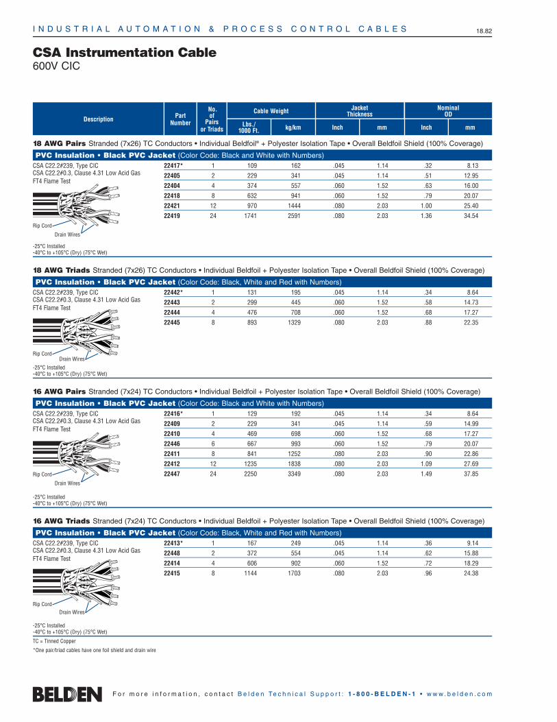
I N D U S T R I A L A U T O M A T I O N & P R O C E S S C O N T R O L C A B L E S 18.82
F o r m o r e i n f o r m a t i o n , c o n t a c t B e l d e n Te c h n i c a l S u p p o r t : 1 - 8 0 0 - B E L D E N - 1 • w w w . b e l d e n . c o m
CSA Instrumentation Cable600V CIC
kg/kmLbs./1000 Ft.
Nominal OD
Jacket ThicknessPart
Number
No.of
Pairsor Triads
Cable Weight
mmInch Inch mm
18 AWG Pairs Stranded (7x26) TC Conductors • Individual Beldfoil® + Polyester Isolation Tape • Overall Beldfoil Shield (100% Coverage)
PVC Insulation • Black PVC Jacket (Color Code: Black and White with Numbers)CSA C22.2#239, Type CIC 22417* 1 109 162 .045 1.14 .32 8.13CSA C22.2#0.3, Clause 4.31 Low Acid Gas 22405 2 229 341 .045 1.14 .51 12.95FT4 Flame Test
22404 4 374 557 .060 1.52 .63 16.00
22418 8 632 941 .060 1.52 .79 20.07
22421 12 970 1444 .080 2.03 1.00 25.40
22419 24 1741 2591 .080 2.03 1.36 34.54
-25°C Installed-40°C to +105°C (Dry) (75°C Wet)
18 AWG Triads Stranded (7x26) TC Conductors • Individual Beldfoil + Polyester Isolation Tape • Overall Beldfoil Shield (100% Coverage)
PVC Insulation • Black PVC Jacket (Color Code: Black, White and Red with Numbers)CSA C22.2#239, Type CIC 22442* 1 131 195 .045 1.14 .34 8.64CSA C22.2#0.3, Clause 4.31 Low Acid Gas 22443 2 299 445 .060 1.52 .58 14.73FT4 Flame Test
22444 4 476 708 .060 1.52 .68 17.27
22445 8 893 1329 .080 2.03 .88 22.35
-25°C Installed-40°C to +105°C (Dry) (75°C Wet)
16 AWG Pairs Stranded (7x24) TC Conductors • Individual Beldfoil + Polyester Isolation Tape • Overall Beldfoil Shield (100% Coverage)
PVC Insulation • Black PVC Jacket (Color Code: Black and White with Numbers)CSA C22.2#239, Type CIC 22416* 1 129 192 .045 1.14 .34 8.64CSA C22.2#0.3, Clause 4.31 Low Acid Gas 22409 2 229 341 .045 1.14 .59 14.99FT4 Flame Test
22410 4 469 698 .060 1.52 .68 17.27
22446 6 667 993 .060 1.52 .79 20.07
22411 8 841 1252 .080 2.03 .90 22.86
22412 12 1235 1838 .080 2.03 1.09 27.69
22447 24 2250 3349 .080 2.03 1.49 37.85
-25°C Installed-40°C to +105°C (Dry) (75°C Wet)
16 AWG Triads Stranded (7x24) TC Conductors • Individual Beldfoil + Polyester Isolation Tape • Overall Beldfoil Shield (100% Coverage)
PVC Insulation • Black PVC Jacket (Color Code: Black, White and Red with Numbers)CSA C22.2#239, Type CIC 22413* 1 167 249 .045 1.14 .36 9.14CSA C22.2#0.3, Clause 4.31 Low Acid Gas 22448 2 372 554 .045 1.14 .62 15.88FT4 Flame Test
22414 4 606 902 .060 1.52 .72 18.29
22415 8 1144 1703 .080 2.03 .96 24.38
-25°C Installed-40°C to +105°C (Dry) (75°C Wet)
TC = Tinned Copper
*One pair/triad cables have one foil shield and drain wire
Description
Rip Cord
Drain Wires
Rip CordDrain Wires
Rip Cord
Drain Wires
Rip CordDrain Wires

I N D U S T R I A L A U T O M A T I O N & P R O C E S S C O N T R O L C A B L E S 18.83
18•
Indu
stria
l Cab
les
F o r m o r e i n f o r m a t i o n , c o n t a c t B e l d e n Te c h n i c a l S u p p o r t : 1 - 8 0 0 - B E L D E N - 1 • w w w . b e l d e n . c o m
CSA Instrumentation Cable600V ACIC Armored Cables
18 AWG Pairs Stranded (7x26) TC Cond. • Individual Beldfoil® + Polyester Isolation Tape • Overall Beldfoil Shield (100% Coverage)
Interlocked Armor • PVC Insulation* • PVC Inner Jacket • Chrome PVC Outer JacketCSA C22.2#239, Type ACIC 24511** 25506** 1 154 229 257 382 .030 .76 .32 8.13 .61 15.49CSA C22.2#174, HLABCD 24512 25514 2 238 354 387 575 .030 .76 .51 12.95 .82 20.83CSA C22.2#0.3, Clause 4.31
24513 25503 4 335 499 504 750 .030 .76 .63 16.00 .93 23.62Low Acid Gas, FT4 Flame Test24514 25505 8 536 798 829 1233 .030 .76 .79 20.27 1.15 29.21
24515 25501 12 739 1100 1092 1624 .030 .76 1.00 25.40 1.36 34.54
24520 25517 24 1169 1740 1674 2490 .030 .76 1.36 34.54 1.75 44.45
-25°C Installed • -40°C to +105°C (Dry) (75°C Wet)
18 AWG Triads Stranded (7x26) TC Conductors • Individual Beldfoil + Polyester Isolation Tape • Overall Beldfoil Shield (100% Coverage)
Interlocked Armor • PVC Insulation* • PVC Inner Jacket • Chrome PVC Outer JacketCSA C22.2#239, Type ACIC 24516** 25500** 1 166 247 276 411 .030 .76 .34 8.64 .63 16.00CSA C22.2#174, HLBCD 24517 25522 2 293 436 455 677 .030 .76 .58 14.73 .89 22.61CSA C22.2#0.3, Clause 4.31
24518 25520 4 391 582 572 851 .030 .76 .66 16.76 .99 25.15Low Acid Gas, FT4 Flame Test24519 25523 8 673 1002 988 1470 .030 .76 .88 22.35 1.29 32.77
-25°C Installed • -40°C to +105°C (Dry) (75°C Wet)
16 AWG Pairs Stranded (7x24) TC Cond. • Individual Beldfoil + Polyester Isolation Tape • Overall Beldfoil Shield (100% Coverage)
Interlocked Armor • PVC Insulation* • PVC Inner Jacket • Chrome PVC Outer JacketCSA C22.2#239, Type ACIC 24500** 25504** 1 171 254 279 415 .030 .76 .34 8.64 .64 16.26CSA C22.2#174, HLABCD 24505 25510 2 299 445 455 677 .030 .76 .59 14.99 .89 22.61CSA C22.2#0.3, Clause 4.31
24502 25511 4 450 670 583 868 .030 .76 .68 17.27 .98 24.89Low Acid Gas, FT4 Flame Test24506 25512 6 576 857 880 1310 .030 .76 .79 20.07 1.16 29.46
24503 25513 8 679 1010 1005 1496 .030 .76 .90 22.86 1.27 32.26
24504 25518 12 908 1351 1280 1905 .030 .76 1.09 27.69 1.46 37.08
24510 25519 24 1502 2235 2030 3021 .030 .76 1.49 37.85 1.88 47.75
-25°C Installed • -40°C to +105°C (Dry) (75°C Wet)
16 AWG Triads Stranded (7x24) TC Conductors • Individual Beldfoil + Polyester Isolation Tape • Overall Beldfoil Shield (100% Coverage)
Interlocked Armor • PVC Insulation* • PVC Inner Jacket • Chrome PVC Outer JacketCSA C22.2#239, Type ACIC 24501** 25502** 1 195 290 309 460 .030 .76 .36 9.14 .66 16.76CSA C22.2#174, HLBCD 24507 25507 2 339 505 465 692 .030 .76 .62 15.75 .94 23.88CSA C22.2#0.3, Clause 4.31
24508 25509 4 464 691 793 1180 .030 .76 .72 18.29 1.05 26.67Low Acid Gas, FT4 Flame Test24509 25508 8 807 1201 1250 1860 .030 .76 .96 24.38 1.33 33.78
-25°C Installed • -40°C to +105°C (Dry) (75°C Wet)
Color Code: Pairs — Black and White with Numbers. TC = Tinned Copper *Note: Add D suffix for XLPE insulation. Example: 24511D.Triads — Black, White and Red with Numbers. **One pair/triad cables have one foil shield and drain wire
SteelArmor
Cable WeightAluminum Armor
Lbs./1000 Ft.
No.of
Pairs/Triads mm
Insulation Thickness
InchDescription
kg/km
Cable WeightSteel Armor
AluminumArmor
Part No.
Lbs./1000 Ft. kg/km mm
Nominal ODInner Jacket
Inch mm
Nominal ODOuter Jacket
Inch
Rip CordDrain Wires
Rip CordDrain Wires
Rip CordDrain Wires
Rip CordDrain Wires
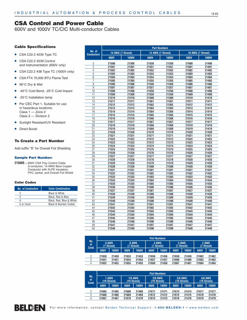
I N D U S T R I A L A U T O M A T I O N & P R O C E S S C O N T R O L C A B L E S 18.84
F o r m o r e i n f o r m a t i o n , c o n t a c t B e l d e n Te c h n i c a l S u p p o r t : 1 - 8 0 0 - B E L D E N - 1 • w w w . b e l d e n . c o m
600V 1000V
2 AWG(7 Strand)
600V 1000V
3 AWG(7 Strand)
600V 1000V
4 AWG(7 Strand)
600V 1000V
6 AWG(7 Strand)
CSA Control and Power Cable 600V and 1000V TC/CIC Multi-conductor Cables
Part Numbers
600V 1000V 600V 1000V 600V 1000V
No. ofConductors 14 AWG (7 Strand) 12 AWG (7 Strand) 10 AWG (7 Strand)
Part Numbers
600V 1000V
No.of
Cond.
8 AWG(7 Strand)
2 21650 21450 21653 21453 21656 21456 21659 21459 21662 214623 21651 21451 21654 21454 21657 21457 21660 21460 21663 214634 21652 21452 21655 21455 21658 21458 21661 21461 21664 21464
Cable Specifications
CSA C22.2 #230 Type TC
CSA C22.2 #239 Control and Instrumentation (600V only)
CSA C22.2 #38 Type TC (1000V only)
CSA FT4 70,000 BTU Flame Test
90°C Dry & Wet
-40°C Cold Bend, -25°C Cold Impact
-25°C Installation temp
Per CEC Part 1, Suitable for use in hazardous locations: Class 1 — Zone 2 Class 2 — Division 2
Sunlight Resistant/UV Resistant
Direct Burial
To Create a Part Number
Add suffix “S” for Overall Foil Shielding
Sample Part Number:
21500S = 600V CSA Tray Control Cable2-conductor, 14 AWG Bare CopperConductor with XLPE Insulation, PVC Jacket, and Overall Foil Shield
No. of Conductors Color Combination
Color Codes
2 Black & White3 Black, Red & Blue4 Black, Red, Blue & White5 or more Black & Number Coded
600V 1000V
4/0 AWG(19 Strand)
600V 1000V
3/0 AWG(19 Strand)
600V 1000V
2/0 AWG(19 Strand)
600V 1000V
1/0 AWG(19 Strand)
Part Numbers
600V 1000V
No.of
Cond.
1 AWG(19 Strand)
2 21665 21465 21668 21468 21671 21471 21674 21474 21677 214773 21666 21466 21669 21469 21672 21472 21675 21475 21678 214784 21667 21467 21670 21470 21673 21473 21676 21476 21679 21479
2 21500 21300 21550 21350 21600 214003 21501 21301 21551 21351 21601 214014 21502 21302 21552 21352 21602 214025 21503 21303 21553 21353 21603 214036 21504 21304 21554 21354 21604 214047 21505 21305 21555 21355 21605 214058 21506 21306 21556 21356 21606 214069 21507 21307 21557 21357 21607 2140710 21508 21308 21558 21358 21608 2140811 21509 21309 21559 21359 21609 2140912 21510 21310 21560 21360 21610 2141013 21511 21311 21561 21361 21611 2141114 21512 21312 21562 21362 21612 2141215 21513 21313 21563 21363 21613 2141316 21514 21314 21564 21364 21614 2141417 21515 21315 21565 21365 21615 2141518 21516 21316 21566 21366 21616 2141619 21517 21317 21567 21367 21617 2141720 21518 21318 21568 21368 21618 2141821 21519 21319 21569 21369 21619 2141922 21520 21320 21570 21370 21620 2142023 21521 21321 21571 21371 21621 2142124 21522 21322 21572 21372 21622 2142225 21523 21323 21573 21373 21623 2142326 21524 21324 21574 21374 21624 2142427 21525 21325 21575 21375 21625 2142528 21526 21326 21576 21376 21626 2142629 21527 21327 21577 21377 21627 2142730 21528 21328 21578 21378 21628 2142831 21529 21329 21579 21379 21629 2142932 21530 21330 21580 21380 21630 2143033 21531 21331 21581 21381 21631 2143134 21532 21332 21582 21382 21632 2143235 21533 21333 21583 21383 21633 2143336 21534 21334 21584 21384 21634 2143437 21535 21335 21585 21385 21635 2143538 21536 21336 21586 21386 21636 2143639 21537 21337 21587 21387 21637 2143740 21538 21338 21588 21388 21638 2143841 21539 21339 21589 21389 21639 2143942 21540 21340 21590 21390 21640 2144043 21541 21341 21591 21391 21641 2144144 21542 21342 21592 21392 21642 2144245 21543 21343 21593 21393 21643 2144346 21544 21344 21594 21394 21644 2144447 21545 21345 21595 21395 21645 2144548 21546 21346 21596 21396 21646 2144649 21547 21347 21597 21397 21647 2144750 21548 21348 21598 21398 21648 21448

I N D U S T R I A L A U T O M A T I O N & P R O C E S S C O N T R O L C A B L E S 18.85
18•
Indu
stria
l Cab
les
F o r m o r e i n f o r m a t i o n , c o n t a c t B e l d e n Te c h n i c a l S u p p o r t : 1 - 8 0 0 - B E L D E N - 1 • w w w . b e l d e n . c o m
CSA Control Cable600V CIC Multi-conductor Cables
No.of
Cond.
Cable Weight
Lbs./1000 Ft.
Description PartNumber
14 AWG Stranded (7x22) Bare Copper Conductors
Cross-linked Polyethylene Insulation • Black PVC Jacket (Color Code: Black and Numbered)CSA C22.2#131, Type CIC 22100 2 62 92 .030 .76 .045 1.14 .367 9.32CSA C22.2#0.3, Clause 4.31 Low Acid Gas 22101 3 81 121 .030 .76 .045 1.14 .388 9.86FT4 Flame Test
22102 4 101 150 .030 .76 .045 1.14 .423 10.74
22103 5 122 182 .030 .76 .045 1.14 .462 11.74
22104 6 143 213 .030 .76 .045 1.14 .504 12.80
22105 7 160 238 .030 .76 .045 1.14 .504 12.80
22106 8 197 293 .030 .76 .060 1.52 .576 14.63
22107 9 220 327 .030 .76 .060 1.52 .618 15.70
22108 10 226 336 .030 .76 .060 1.52 .669 17.00
22110 12 279 415 .030 .76 .060 1.52 .689 17.50
-25°C Installed22114 16 357 531 .030 .76 .060 1.52 .764 19.41
-40°C to +90°C (Dry) (75°C Wet) 22118 20 467 695 .030 .76 .080 2.03 .886 22.50
12 AWG Stranded (7x20) Bare Copper Conductors
Cross-linked Polyethylene Insulation • Black PVC Jacket (Color Code: Black and Numbered)CSA C22.2#131, Type CIC 22120 2 82 122 .030 .76 .045 1.14 .405 10.29CSA C22.2#0.3, Clause 4.31 Low Acid Gas 22121 3 109 162 .030 .76 .045 1.14 .429 10.90FT4 Flame Test
22122 4 140 208 .030 .76 .045 1.14 .469 11.91
22123 5 170 253 .030 .76 .045 1.14 .515 13.08
22124 6 214 319 .030 .76 .060 1.52 .591 15.01
22125 7 240 357 .030 .76 .060 1.52 .591 15.01
22126 8 270 402 .030 .76 .060 1.52 .639 16.23
22127 9 302 449 .030 .76 .060 1.52 .687 17.45
22128 10 336 500 .030 .76 .060 1.52 .745 18.92
22130 12 390 580 .030 .76 .060 1.52 .768 19.51
-25°C Installed22134 16 584 869 .030 .76 .080 2.03 .893 22.68
-40°C to +90°C (Dry) (75°C Wet) 22138 20 655 975 .030 .76 .080 2.03 .992 25.20
10 AWG Stranded (7x18) Bare Copper Conductors
Cross-linked Polyethylene Insulation • Black PVC Jacket (Color Code: Black and Numbered)CSA C22.2#131, Type CIC 22140 2 148 220 .030 .76 .045 1.14 .736 18.69CSA C22.2#0.3, Clause 4.31 Low Acid Gas 22141 3 189 281 .030 .76 .045 1.14 .763 19.38FT4 Flame Test
22142 4 248 369 .030 .76 .060 1.52 .839 21.31
22143 5 293 436 .030 .76 .060 1.52 .891 22.63
22144 6 338 503 .030 .76 .060 1.52 .944 23.98
22145 7 378 563 .030 .76 .060 1.52 .944 23.98
22146 8 424 631 .030 .76 .060 1.52 .999 25.38
22147 9 469 698 .030 .76 .060 1.52 1.074 27.28
22148 10 548 816 .030 .76 .080 2.03 1.182 30.02
22150 12 631 939 .030 .76 .080 2.03 1.209 30.71
-25°C Installed22152 14 717 1067 .030 .76 .080 2.03 1.255 31.88
-40°C to +90°C (Dry) (75°C Wet) 22154 16 805 1198 .030 .76 .080 2.03 1.307 33.20
Jacket Thickness
Inchmm
Insulation Thickness
Inch
Nominal OD
mm mmkg/km Inch
Rip Cord
Rip Cord
Rip Cord
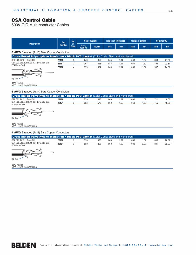
I N D U S T R I A L A U T O M A T I O N & P R O C E S S C O N T R O L C A B L E S 18.86
F o r m o r e i n f o r m a t i o n , c o n t a c t B e l d e n Te c h n i c a l S u p p o r t : 1 - 8 0 0 - B E L D E N - 1 • w w w . b e l d e n . c o m
CSA Control Cable600V CIC Multi-conductor Cables
8 AWG Stranded (7x16) Bare Copper Conductors
Cross-linked Polyethylene Insulation • Black PVC Jacket (Color Code: Black and Numbered)CSA C22.2#131, Type CIC 22160 2 240 357 .045 1.14 .060 1.52 .863 21.92CSA C22.2#0.3, Clause 4.31 Low Acid Gas 22161 3 308 458 .045 1.14 .060 1.52 .898 22.81FT4 Flame Test
22162 4 379 564 .045 1.14 .060 1.52 .957 24.31
-25°C Installed-40°C to +90°C (Dry) (75°C Wet)
6 AWG Stranded (7x14) Bare Copper Conductors
Cross-linked Polyethylene Insulation • Black PVC Jacket (Color Code: Black and Numbered)CSA C22.2#131, Type CIC 22170 2 279 415 .060 1.52 .060 1.52 .711 18.06CSA C22.2#0.3, Clause 4.31 Low Acid Gas 22171 3 383 570 .060 1.52 .060 1.52 .756 19.20FT4 Flame Test
-25°C Installed-40°C to +90°C (Dry) (75°C Wet)
4 AWG Stranded (7x12) Bare Copper Conductors
Cross-linked Polyethylene Insulation • Black PVC Jacket (Color Code: Black and Numbered)CSA C22.2#131, Type CIC 22180 2 390 580 .060 1.52 .060 1.52 .800 20.32CSA C22.2#0.3, Clause 4.31 Low Acid Gas 22181 3 580 863 .060 1.52 .080 2.03 .891 22.63FT4 Flame Test
-25°C Installed-40°C to +90°C (Dry) (75°C Wet)
No.of
Cond.
Cable Weight
Lbs./1000 Ft.
Description PartNumber
Jacket Thickness
Inchmm
Insulation Thickness
Inch
Nominal OD
mm mmkg/km Inch
Rip Cord
Rip Cord
Rip Cord
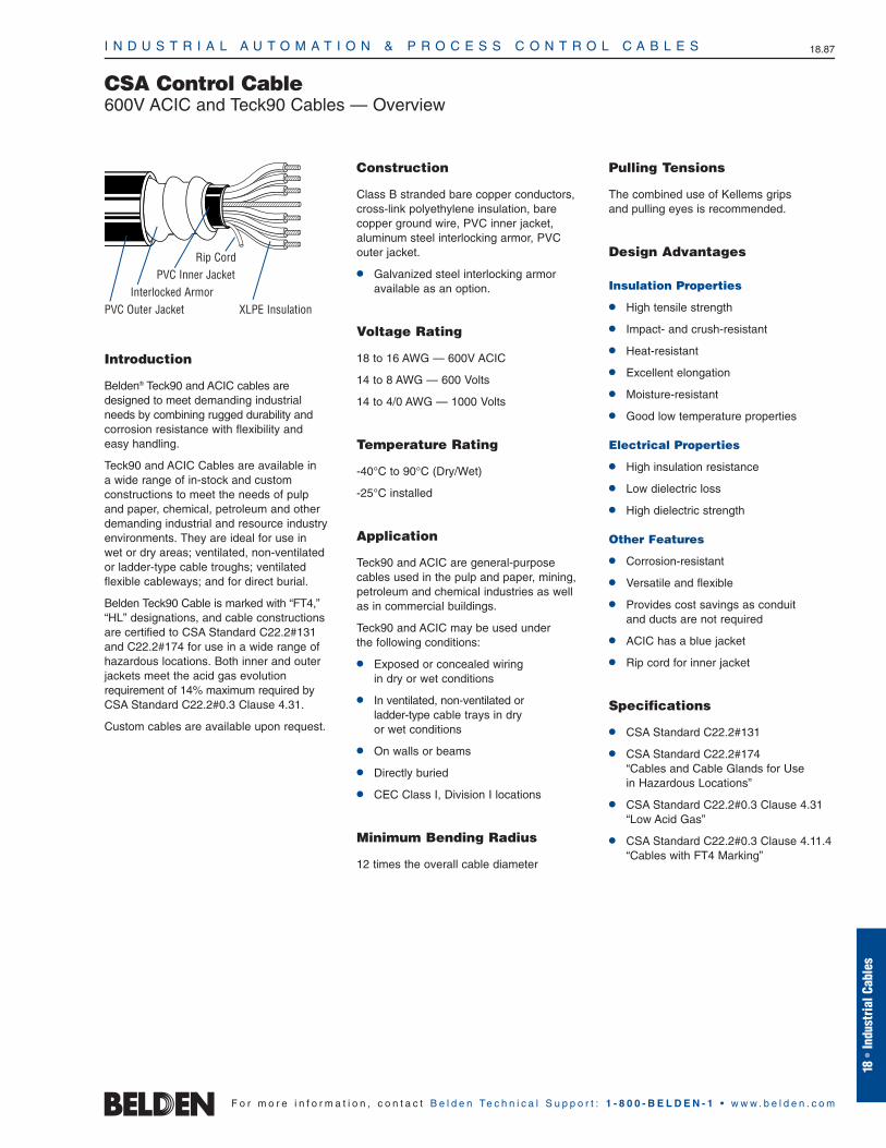
I N D U S T R I A L A U T O M A T I O N & P R O C E S S C O N T R O L C A B L E S 18.87
18•
Indu
stria
l Cab
les
CSA Control Cable600V ACIC and Teck90 Cables — Overview
Introduction
Belden® Teck90 and ACIC cables aredesigned to meet demanding industrialneeds by combining rugged durability andcorrosion resistance with flexibility andeasy handling.
Teck90 and ACIC Cables are available in a wide range of in-stock and custom constructions to meet the needs of pulpand paper, chemical, petroleum and otherdemanding industrial and resource industryenvironments. They are ideal for use in wet or dry areas; ventilated, non-ventilatedor ladder-type cable troughs; ventilatedflexible cableways; and for direct burial.
Belden Teck90 Cable is marked with “FT4,”“HL” designations, and cable constructionsare certified to CSA Standard C22.2#131and C22.2#174 for use in a wide range of hazardous locations. Both inner and outerjackets meet the acid gas evolution requirement of 14% maximum required byCSA Standard C22.2#0.3 Clause 4.31.
Custom cables are available upon request.
Construction
Class B stranded bare copper conductors,cross-link polyethylene insulation, barecopper ground wire, PVC inner jacket, aluminum steel interlocking armor, PVCouter jacket.
Galvanized steel interlocking armoravailable as an option.
Voltage Rating
18 to 16 AWG — 600V ACIC
14 to 8 AWG — 600 Volts
14 to 4/0 AWG — 1000 Volts
Temperature Rating
-40°C to 90°C (Dry/Wet)
-25°C installed
Application
Teck90 and ACIC are general-purpose cables used in the pulp and paper, mining,petroleum and chemical industries as wellas in commercial buildings.
Teck90 and ACIC may be used under the following conditions:
Exposed or concealed wiring in dry or wet conditions
In ventilated, non-ventilated or ladder-type cable trays in dry or wet conditions
On walls or beams
Directly buried
CEC Class I, Division I locations
Minimum Bending Radius
12 times the overall cable diameter
Pulling Tensions
The combined use of Kellems grips and pulling eyes is recommended.
Design Advantages
Insulation Properties
High tensile strength
Impact- and crush-resistant
Heat-resistant
Excellent elongation
Moisture-resistant
Good low temperature properties
Electrical Properties
High insulation resistance
Low dielectric loss
High dielectric strength
Other Features
Corrosion-resistant
Versatile and flexible
Provides cost savings as conduit and ducts are not required
ACIC has a blue jacket
Rip cord for inner jacket
Specifications
CSA Standard C22.2#131
CSA Standard C22.2#174 “Cables and Cable Glands for Use in Hazardous Locations”
CSA Standard C22.2#0.3 Clause 4.31“Low Acid Gas”
CSA Standard C22.2#0.3 Clause 4.11.4“Cables with FT4 Marking”
PVC Outer JacketInterlocked Armor
PVC Inner JacketRip Cord
XLPE Insulation
F o r m o r e i n f o r m a t i o n , c o n t a c t B e l d e n Te c h n i c a l S u p p o r t : 1 - 8 0 0 - B E L D E N - 1 • w w w . b e l d e n . c o m

Description PartNo.
No.of
Cond. kg/kmLbs./1000 Ft.
Cable Weight
18 AWG Stranded (7x26) Bare Copper Conductors • 18 AWG Bare Copper Ground Wire
Aluminum Interlocked Armor • .030″ (.76mm) XLPE Insulation • PVC Inner Jacket • Blue PVC Outer JacketCSA C22.2#239 29030 2 163 243 .32 8.13 .52 13.21 .62 15.75 44 196 7.4 187.96FT4 Flame Test 29031 3 177 263 .34 8.64 .54 13.72 .64 16.26 66 294 7.6 193.04
29032 4 195 290 .37 9.40 .57 14.48 .67 17.02 88 392 8.0 203.20
29033 5 219 326 .41 10.41 .61 15.49 .71 18.03 110 490 8.5 215.90
29034 6 239 356 .45 11.43 .65 16.51 .75 19.05 132 587 9.0 228.60
29035 7 245 365 .45 11.43 .65 16.51 .75 19.05 154 685 9.0 228.60
29036 8 266 396 .48 12.19 .68 17.27 .78 19.81 176 783 9.3 236.22
29038 10 331 493 .56 14.22 .76 19.30 .87 22.10 220 979 10.6 269.24
29040 12 353 525 .62 15.75 .82 20.83 .93 23.62 264 1175 11.1 281.94
29043 15 401 597 .65 16.51 .85 21.59 .96 24.38 330 1469 11.5 292.10
29048 20 466 694 .73 18.54 .93 23.62 1.04 26.42 440 1958 12.4 314.96
29053 25 589 877 .79 20.07 1.05 26.67 1.16 29.46 550 2448 13.9 353.06
29058 30 698 1039 .88 22.35 1.14 28.96 1.25 31.75 660 2937 15.0 381.00
HAZ LOC29068 40 827 1231 .97 24.64 1.23 31.24 1.35 34.29 880 3916 16.2 411.48
CSA C22.2#0.3 Clause 4.31 Low Acid Gas 29078 50 965 1436 1.09 27.69 1.35 34.29 1.47 37.34 1100 4895 17.6 447.04
16 AWG Stranded (7x24) Bare Copper Conductors • 16 AWG Bare Copper Ground Wire
Aluminum Interlocked Armor • .030″ (.76mm) XLPE Insulation • PVC Inner Jacket • Blue PVC Outer JacketCSA C22.2#239 29017 2 202 301 .34 8.64 .54 13.72 .65 16.51 70 312 7.7 195.58FT4 Flame Test 29004 3 221 329 .36 9.14 .56 14.22 .66 16.76 105 467 7.9 200.66
29018 4 242 360 .39 9.91 .59 14.99 .70 17.78 140 623 8.3 210.82
29019 5 264 393 .42 10.67 .62 15.75 .73 18.54 175 779 8.6 218.44
29005 6 292 435 .46 11.68 .66 16.76 .77 19.56 210 935 9.1 231.14
29020 7 314 467 .47 11.94 .67 17.02 .77 19.56 245 1090 9.2 233.68
29021 8 364 542 .50 12.70 .70 17.78 .80 20.32 280 1246 9.6 243.84
29022 10 412 613 .61 15.49 .81 20.57 .92 23.37 350 1558 10.9 276.86
29006 12 441 656 .63 16.00 .83 21.08 .94 23.88 420 1869 11.2 284.48
29023 15 502 748 .68 17.27 .88 22.35 1.00 25.40 525 2336 11.9 302.26
29007 20 636 947 .77 19.56 1.03 26.16 1.13 28.70 700 3115 13.7 347.98
29024 25 845 1258 .89 22.61 1.15 29.21 1.26 32.00 875 3894 15.1 383.54
29008 30 922 1372 .94 23.88 1.20 30.48 1.30 33.02 1050 4673 15.8 401.32
29009 40 1109 1650 1.06 26.92 1.32 33.53 1.41 35.81 1400 6230 17.3 439.42
HAZ LOC29016 50 1306 1944 1.19 30.23 1.45 36.83 1.54 39.12 1750 7788 18.8 477.52
CSA C22.2#0.3 Clause 4.31 Low Acid Gas 29025 60 1390 2070 1.27 32.26 1.53 38.86 1.66 42.16 2100 9345 19.9 505.46XLPE = Cross-linked Polyethylene
Color Code: #1 conductor is white; remaining conductors are black with number coding. Other color codes available upon request.
CSA Control Cable600V ACIC Cables
I N D U S T R I A L A U T O M A T I O N & P R O C E S S C O N T R O L C A B L E S 18.88
F o r m o r e i n f o r m a t i o n , c o n t a c t B e l d e n Te c h n i c a l S u p p o r t : 1 - 8 0 0 - B E L D E N - 1 • w w w . b e l d e n . c o m
mm
Armor OD
Inch
Outer Jacket
Inchmm
Inner Jacket OD
mm Lbs. N
MaximumPull Tension
Inch
MinimumBend Radius
Inch mm
Rip Cord
Rip Cord

Lbs./1000 Ft.
Cable WeightNo.of
Cond.
PartNo.Description
I N D U S T R I A L A U T O M A T I O N & P R O C E S S C O N T R O L C A B L E S 18.89
18•
Indu
stria
l Cab
les
F o r m o r e i n f o r m a t i o n , c o n t a c t B e l d e n Te c h n i c a l S u p p o r t : 1 - 8 0 0 - B E L D E N - 1 • w w w . b e l d e n . c o m
kg/km mm
Armor OD
Inch
Outer Jacket
Inchmm
Inner Jacket OD
mm Lbs. N
MaximumPull Tension
Inch
MinimumBend Radius
Inch mm
14 AWG Stranded (7x22) Bare Copper Conductors • 14 AWG Bare Copper Ground Wire
Aluminum Interlocked Armor • .030″ (.76mm) XLPE Insulation • PVC Inner Jacket • Black PVC Outer JacketCSA C22.2#131 C5500 2 198 296 .36 9.14 .56 14.22 .66 16.76 108 481 7.8 198.12FT4 Flame Test C5501 3 222 331 .39 9.91 .58 14.73 .66 16.76 162 721 8.2 208.28
C5502 4 251 375 .42 10.67 .62 15.75 .71 18.03 216 961 8.5 215.90
C5503 5 284 424 .47 11.94 .66 16.76 .74 18.80 270 1202 9.0 228.60
C5504 6 317 473 .51 12.95 .70 17.78 .78 19.81 324 1442 9.5 241.30
C5505 7 331 494 .51 12.95 .70 17.78 .78 19.81 378 1682 9.5 241.30
C5506 8 414 618 .58 14.73 .77 19.56 .86 21.84 432 1922 10.4 264.16
C5508 10 510 761 .67 17.02 .93 23.62 .95 24.13 540 2403 12.3 312.42
C5510 12 551 822 .69 17.53 .95 24.13 .97 24.64 648 2884 12.6 320.04
C5513 15 636 949 .77 19.56 1.03 26.16 1.11 28.19 810 3605 14.1 358.14
C5518 20 810 1209 .90 22.86 1.16 29.46 1.24 31.50 1080 4806 15.1 383.54
C5523 25 948 1415 .90 22.86 1.24 31.50 1.33 33.78 1350 6008 16.1 408.94
C5528 30 1047 1563 1.05 26.67 1.30 33.02 1.40 35.56 1620 7209 16.8 426.72
HAZ LOCC5529 40 1310 1955 1.20 30.48 1.42 36.07 1.51 38.35 2160 9612 18.3 464.82
CSA C22.2#0.3 Clause 4.31 Low Acid Gas C6064 50 1620 2418 1.35 34.29 1.60 40.64 1.66 42.16 2700 12015 20.5 520.70
12 AWG Stranded (7x20) Bare Copper Conductors • 14 AWG Bare Copper Ground Wire
Aluminum Interlocked Armor • .030″ (.76mm) XLPE Insulation • PVC Inner Jacket • Black PVC Outer JacketCSA C22.2#131 C5530 2 225 336 .41 10.41 .60 15.24 .69 17.53 172 765 8.3 210.82FT4 Flame Test C5531 3 261 390 .43 10.92 .62 15.75 .70 17.78 258 1148 8.6 218.44
C5532 4 301 449 .47 11.94 .66 16.76 .73 18.54 344 1531 9.1 231.14
C5533 5 348 519 .52 13.21 .71 18.03 .78 19.81 430 1914 9.1 231.14
C5534 6 435 649 .59 14.99 .78 19.81 .86 21.84 516 2296 10.5 266.70
C5535 7 450 672 .59 14.99 .78 19.81 .86 21.84 602 2679 10.5 266.70
C5536 8 506 755 .64 16.26 .83 21.08 .92 23.37 688 3062 11.1 281.94
C5538 10 633 945 .75 19.05 1.01 25.65 1.02 25.91 860 3827 13.3 337.82
C5540 12 696 1039 .77 19.56 1.03 26.16 1.12 28.45 1032 4592 13.5 342.90
C5543 15 823 1228 .90 22.86 1.16 29.46 1.24 31.50 1290 5741 15.1 383.54
C5548 20 1035 1545 .99 25.15 1.25 31.75 1.34 34.04 1720 7654 16.5 419.10
HAZ LOCC5553 25 1230 1836 1.10 27.94 1.36 34.54 1.45 36.83 2150 9568 17.6 447.04
CSA C22.2#0.3 Clause 4.31 Low Acid Gas C5558 30 1390 2075 1.20 30.48 1.46 37.08 1.51 38.35 2580 11481 17.6 447.04XLPE = Cross-linked Polyethylene
Color Code: 2 conductors — Black, White (If required, a Red conductor can be used in place of White.)3 conductors — Black, Red, Blue (If required, a White conductor can be used in place of Blue.)4 conductors — Black, Red, Blue, White5 or more conductors — Black and numbered
CSA Control Cable600V Teck90 Cables
Rip Cord
Rip Cord
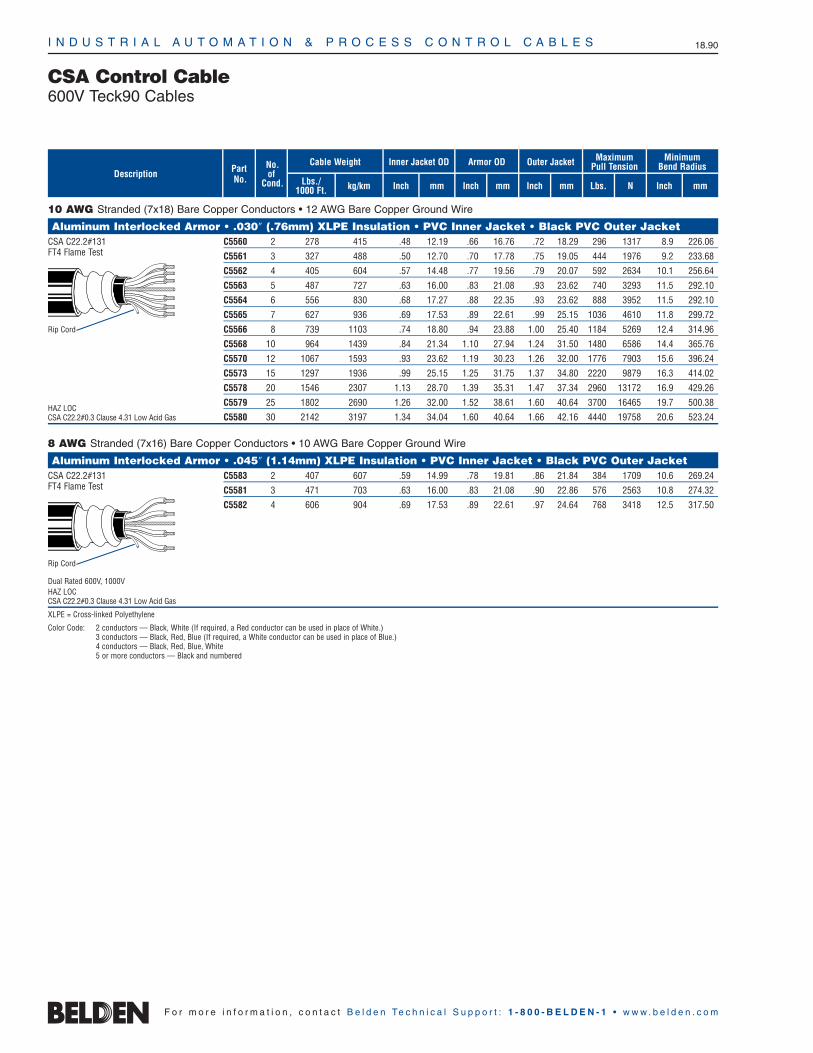
No.of
Cond.
PartNo.
I N D U S T R I A L A U T O M A T I O N & P R O C E S S C O N T R O L C A B L E S 18.90
F o r m o r e i n f o r m a t i o n , c o n t a c t B e l d e n Te c h n i c a l S u p p o r t : 1 - 8 0 0 - B E L D E N - 1 • w w w . b e l d e n . c o m
10 AWG Stranded (7x18) Bare Copper Conductors • 12 AWG Bare Copper Ground Wire
Aluminum Interlocked Armor • .030″ (.76mm) XLPE Insulation • PVC Inner Jacket • Black PVC Outer JacketCSA C22.2#131 C5560 2 278 415 .48 12.19 .66 16.76 .72 18.29 296 1317 8.9 226.06FT4 Flame Test C5561 3 327 488 .50 12.70 .70 17.78 .75 19.05 444 1976 9.2 233.68
C5562 4 405 604 .57 14.48 .77 19.56 .79 20.07 592 2634 10.1 256.64
C5563 5 487 727 .63 16.00 .83 21.08 .93 23.62 740 3293 11.5 292.10
C5564 6 556 830 .68 17.27 .88 22.35 .93 23.62 888 3952 11.5 292.10
C5565 7 627 936 .69 17.53 .89 22.61 .99 25.15 1036 4610 11.8 299.72
C5566 8 739 1103 .74 18.80 .94 23.88 1.00 25.40 1184 5269 12.4 314.96
C5568 10 964 1439 .84 21.34 1.10 27.94 1.24 31.50 1480 6586 14.4 365.76
C5570 12 1067 1593 .93 23.62 1.19 30.23 1.26 32.00 1776 7903 15.6 396.24
C5573 15 1297 1936 .99 25.15 1.25 31.75 1.37 34.80 2220 9879 16.3 414.02
C5578 20 1546 2307 1.13 28.70 1.39 35.31 1.47 37.34 2960 13172 16.9 429.26
HAZ LOCC5579 25 1802 2690 1.26 32.00 1.52 38.61 1.60 40.64 3700 16465 19.7 500.38
CSA C22.2#0.3 Clause 4.31 Low Acid Gas C5580 30 2142 3197 1.34 34.04 1.60 40.64 1.66 42.16 4440 19758 20.6 523.24
8 AWG Stranded (7x16) Bare Copper Conductors • 10 AWG Bare Copper Ground Wire
Aluminum Interlocked Armor • .045″ (1.14mm) XLPE Insulation • PVC Inner Jacket • Black PVC Outer JacketCSA C22.2#131 C5583 2 407 607 .59 14.99 .78 19.81 .86 21.84 384 1709 10.6 269.24FT4 Flame Test C5581 3 471 703 .63 16.00 .83 21.08 .90 22.86 576 2563 10.8 274.32
C5582 4 606 904 .69 17.53 .89 22.61 .97 24.64 768 3418 12.5 317.50
Dual Rated 600V, 1000VHAZ LOCCSA C22.2#0.3 Clause 4.31 Low Acid Gas
XLPE = Cross-linked Polyethylene
Color Code: 2 conductors — Black, White (If required, a Red conductor can be used in place of White.)3 conductors — Black, Red, Blue (If required, a White conductor can be used in place of Blue.)4 conductors — Black, Red, Blue, White5 or more conductors — Black and numbered
CSA Control Cable600V Teck90 Cables
kg/kmLbs./1000 Ft.
Cable Weight
mm
Armor OD
Inch
Outer Jacket
Inchmm
Inner Jacket OD
mm Lbs. N
MaximumPull Tension
InchDescription
MinimumBend Radius
Inch mm
Rip Cord
Rip Cord
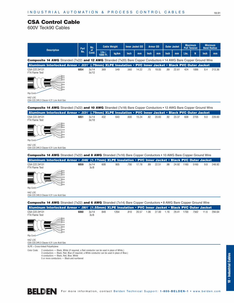
No.of
Cond.
PartNo.Description
I N D U S T R I A L A U T O M A T I O N & P R O C E S S C O N T R O L C A B L E S 18.91
18•
Indu
stria
l Cab
les
F o r m o r e i n f o r m a t i o n , c o n t a c t B e l d e n Te c h n i c a l S u p p o r t : 1 - 8 0 0 - B E L D E N - 1 • w w w . b e l d e n . c o m
CSA Control Cable600V Teck90 Cables
Composite 14 AWG Stranded (7x22) and 12 AWG Stranded (7x20) Bare Copper Conductors • 14 AWG Bare Copper Ground Wire
Aluminum Interlocked Armor • .031″ (.79mm) XLPE Insulation • PVC Inner Jacket • Black PVC Outer JacketCSA C22.2#131 6054 3c/14 369 549 .560 14.22 .75 19.05 .89 22.61 424 1886 8.4 213.36FT4 Flame Test 3c/12
HAZ LOCCSA C22.2#0.3 Clause 4.31 Low Acid Gas
Composite 14 AWG Stranded (7x22) and 10 AWG Stranded (7x18) Bare Copper Conductors • 12 AWG Bare Copper Ground Wire
Aluminum Interlocked Armor • .031″ (.79mm) XLPE Insulation • PVC Inner Jacket • Black PVC Outer JacketCSA C22.2#131 6051 3c/14 432 643 .600 15.24 .82 20.83 .92 23.37 608 2705 9.0 228.60FT4 Flame Test 3c/10
HAZ LOCCSA C22.2#0.3 Clause 4.31 Low Acid Gas
Composite 14 AWG Stranded (7x22) and 8 AWG Stranded (7x16) Bare Copper Conductors • 10 AWG Bare Copper Ground Wire
Aluminum Interlocked Armor • .046″ (1.17mm) XLPE Insulation • PVC Inner Jacket • Black PVC Outer JacketCSA C22.2#131 6059 3c/14 608 905 .700 17.78 .89 22.51 .98 24.92 1160 5160 9.8 248.92FT4 Flame Test 3c/8
HAZ LOCCSA C22.2#0.3 Clause 4.31 Low Acid Gas
Composite 14 AWG Stranded (7x22) and 6 AWG Stranded (7x14) Bare Copper Conductors • 8 AWG Bare Copper Ground Wire
Aluminum Interlocked Armor • .061″ (1.55mm) XLPE Insulation • PVC Inner Jacket • Black PVC Outer JacketCSA C22.2#131 6060 3c/14 849 1264 .810 20.57 1.06 27.00 1.16 29.41 1700 7562 11.6 294.64FT4 Flame Test 3c/6
HAZ LOCCSA C22.2#0.3 Clause 4.31 Low Acid Gas
XLPE = Cross-linked Polyethylene
Color Code: 2 conductors — Black, White (If required, a Red conductor can be used in place of White.)3 conductors — Black, Red, Blue (If required, a White conductor can be used in place of Blue.)4 conductors — Black, Red, Blue, White5 or more conductors — Black and numbered
kg/kmLbs./1000 Ft.
Cable Weight
mm
Armor OD
Inch
Outer Jacket
Inchmm
Inner Jacket OD
mm Lbs. N
MaximumPull Tension
Inch
MinimumBend Radius
Inch mm
Rip Cord
Rip Cord
Rip Cord
Rip Cord

I N D U S T R I A L A U T O M A T I O N & P R O C E S S C O N T R O L C A B L E S 18.92
F o r m o r e i n f o r m a t i o n , c o n t a c t B e l d e n Te c h n i c a l S u p p o r t : 1 - 8 0 0 - B E L D E N - 1 • w w w . b e l d e n . c o m
kg/kmLbs./1000 Ft.
Cable Weight
mm
Armor OD
Inch
Outer Jacket
Inchmm
Inner Jacket OD
mm Lbs. N
MaximumPull Tension
Inch
PartNo.Description
MinimumBend RadiusNo.
ofCond. Inch mm
14 AWG Stranded (7x22) Bare Copper Conductors • 14 AWG Bare Copper Ground Wire
Aluminum Interlocked Armor • .045″ (1.14mm) XLPE Insulation • PVC Inner Jacket • Black PVC Outer JacketCSA C22.2#131 C5701 3 251 374 .47 11.94 .67 17.02 .73 18.54 162 721 9.2 233.68FT4 Flame Test C5702 4 301 448 .51 12.95 .71 18.03 .81 20.57 216 961 9.7 246.38
HAZ LOCCSA C22.2#0.3 Clause 4.31 Low Acid Gas
12 AWG Stranded (7x20) Bare Copper Conductors • 14 AWG Bare Copper Ground Wire
Aluminum Interlocked Armor • .045″ (1.14mm) XLPE Insulation • PVC Inner Jacket • Black PVC Outer JacketCSA C22.2#131 C5730 2 253 377 .48 12.19 .68 17.27 .74 18.80 172 765 9.3 236.22FT4 Flame Test C5731 3 291 433 .51 12.95 .71 18.03 .76 19.30 258 1148 9.7 246.38
C5732 4 368 548 .59 14.99 .75 19.05 .85 21.59 344 1531 10.8 274.32
HAZ LOCCSA C22.2#0.3 Clause 4.31 Low Acid Gas
10 AWG Stranded (7x18) Bare Copper Conductors • 12 AWG Bare Copper Ground Wire
Aluminum Interlocked Armor • .045″ (1.14mm) XLPE Insulation • PVC Inner Jacket • Black PVC Outer JacketCSA C22.2#131 C5760 2 285 424 .56 14.22 .79 19.99 .70 17.71 296 1317 10.3 261.62FT4 Flame Test C5761 3 389 581 .59 14.99 .79 20.07 .85 21.59 444 1976 10.3 261.62
C5762 4 460 687 .65 16.51 .85 21.59 .90 22.86 592 2634 11.5 292.10
HAZ LOCCSA C22.2#0.3 Clause 4.31 Low Acid Gas
8 AWG Stranded (7x16) Bare Copper Conductors • 10 AWG Bare Copper Ground Wire
Aluminum Interlocked Armor • .045″ (1.14mm) XLPE Insulation • PVC Inner Jacket • Black PVC Outer JacketCSA C22.2#131 C5583 2 407 607 .59 14.99 .78 19.81 .86 21.84 384 1709 10.6 269.24FT4 Flame Test C5581 3 471 703 .63 16.00 .83 21.08 .90 22.86 576 2563 10.8 274.32
C5582 4 606 905 .69 17.53 .89 22.61 .97 24.64 768 3418 12.5 317.50
Dual Rated 600V, 1000VHAZ LOCCSA C22.2#0.3 Clause 4.31 Low Acid Gas
XLPE = Cross-linked Polyethylene
Color Code: 2 conductors — Black, White (If required, a Red conductor can be used in place of White.)3 conductors — Black, Red, Blue (If required, a White conductor can be used in place of Blue.)4 conductors — Black, Red, Blue, White5 or more conductors — Black and numbered
CSA Control Cable1000V Teck90 Cables
Rip Cord
Rip Cord
Rip Cord
Rip Cord

No.of
Cond.
I N D U S T R I A L A U T O M A T I O N & P R O C E S S C O N T R O L C A B L E S 18.93
18•
Indu
stria
l Cab
les
F o r m o r e i n f o r m a t i o n , c o n t a c t B e l d e n Te c h n i c a l S u p p o r t : 1 - 8 0 0 - B E L D E N - 1 • w w w . b e l d e n . c o m
6 AWG Stranded (7x14) Bare Copper Conductors • 8 AWG Bare Copper Ground Wire
Aluminum Interlocked Armor • .060″ (1.53mm) XLPE Insulation • PVC Inner Jacket • Black PVC Outer JacketCSA C22.2#131 C5590 2 567 844 .73 18.54 .99 25.15 1.10 27.94 610 2713 12.8 325.12FT4 Flame Test C5591 3 685 1019 .78 19.81 1.04 26.42 1.15 29.21 915 4072 13.4 340.36
C5592 4 927 1380 .89 22.61 1.15 29.21 1.24 31.50 1220 5429 14.9 378.46
HAZ LOCCSA C22.2#0.3 Clause 4.31 Low Acid Gas
4 AWG Stranded (7x12) Bare Copper Conductors • 8 AWG Bare Copper Ground Wire
Aluminum Interlocked Armor • .060″ (1.53mm) XLPE Insulation • PVC Inner Jacket • Black PVC Outer JacketCSA C22.2#131 C5601 3 961 1430 .91 23.11 1.17 29.72 1.23 31.24 1455 6475 15.2 386.08FT4 Flame Test C5602 4 1202 1794 .91 23.11 1.25 31.75 1.33 33.78 1940 8633 16.2 411.48
HAZ LOCCSA C22.2#0.3 Clause 4.31 Low Acid Gas
3 AWG Stranded (7x11) Bare Copper Conductors • 6 AWG Bare Copper Ground Wire
Aluminum Interlocked Armor • .060″ (1.53mm) XLPE Insulation • PVC Inner Jacket • Black PVC Outer JacketCSA C22.2#131 C5611 3 1126 1681 .97 24.64 1.23 31.24 1.30 33.02 1836 8170 15.8 401.32FT4 Flame Test
HAZ LOCCSA C22.2#0.3 Clause 4.31 Low Acid Gas
2 AWG Stranded (7x10) Bare Copper Conductors • 6 AWG Bare Copper Ground Wire
Aluminum Interlocked Armor • .060″ (1.53mm) XLPE Insulation • PVC Inner Jacket • Black PVC Outer JacketCSA C22.2#131 C5621 3 1291 1927 1.02 25.91 1.28 32.51 1.37 34.80 2316 10302 16.5 419.10FT4 Flame Test C5622 4 1691 2524 1.12 28.45 1.38 35.05 1.48 37.59 3088 13736 17.7 449.58
HAZ LOCCSA C22.2#0.3 Clause 4.31 Low Acid Gas
XLPE = Cross-linked Polyethylene
Color Code: 2 conductors — Black, White (If required, a Red conductor can be used in place of White.)3 conductors — Black, Red, Blue (If required, a White conductor can be used in place of Blue.)4 conductors — Black, Red, Blue, White
CSA Control Cable1000V Teck90 Cables
kg/kmLbs./1000 Ft.
Cable Weight
mm
Armor OD
Inch
Outer Jacket
Inchmm
Inner Jacket OD
mm Lbs. N
MaximumPull Tension
Inch
PartNo.Description
MinimumBend Radius
Inch mm
Rip Cord
Rip Cord
Rip Cord
Rip Cord
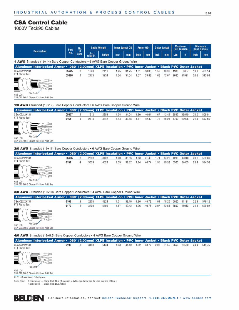
No.of
Cond.
I N D U S T R I A L A U T O M A T I O N & P R O C E S S C O N T R O L C A B L E S 18.94
F o r m o r e i n f o r m a t i o n , c o n t a c t B e l d e n Te c h n i c a l S u p p o r t : 1 - 8 0 0 - B E L D E N - 1 • w w w . b e l d e n . c o m
kg/kmLbs./1000 Ft.
Cable Weight
mm
Armor OD
Inch
Outer Jacket
Inchmm
Inner Jacket OD
mm Lbs. N
MaximumPull Tension
Inch
PartNo.Description
MinimumBend Radius
Inch mm
1 AWG Stranded (19x14) Bare Copper Conductors • 6 AWG Bare Copper Ground Wire
Aluminum Interlocked Armor • .080″ (2.03mm) XLPE Insulation • PVC Inner Jacket • Black PVC Outer JacketCSA C22.2#131 C5625 3 1620 2411 1.25 31.75 1.51 38.35 1.59 40.39 1980 8807 19.1 485.14FT4 Flame Test C5626 4 2173 3234 1.34 34.04 1.57 39.88 1.68 42.67 2680 11921 20.2 513.08
HAZ LOCCSA C22.2#0.3 Clause 4.31 Low Acid Gas
1/0 AWG Stranded (19x12) Bare Copper Conductors • 6 AWG Bare Copper Ground Wire
Aluminum Interlocked Armor • .080″ (2.03mm) XLPE Insulation • PVC Inner Jacket • Black PVC Outer JacketCSA C22.2#131 C5627 3 1912 2854 1.34 34.04 1.60 40.64 1.67 42.42 3582 15940 20.0 508.0FT4 Flame Test 6164 4 2514 3742 1.44 36.58 1.67 42.42 1.78 45.21 4700 20906 21.4 543.56
HAZ LOCCSA C22.2#0.3 Clause 4.31 Low Acid Gas
2/0 AWG Stranded (19x11) Bare Copper Conductors • 6 AWG Bare Copper Ground Wire
Aluminum Interlocked Armor • .080″ (2.03mm) XLPE Insulation • PVC Inner Jacket • Black PVC Outer JacketCSA C22.2#131 C5635 3 2300 3423 1.40 35.56 1.63 41.40 1.74 44.20 4200 12010 20.9 530.86FT4 Flame Test 6157 4 3039 4523 1.55 39.37 1.84 46.74 1.95 49.53 5500 24465 23.4 594.36
HAZ LOCCSA C22.2#0.3 Clause 4.31 Low Acid Gas
3/0 AWG Stranded (19x10) Bare Copper Conductors • 4 AWG Bare Copper Ground Wire
Aluminum Interlocked Armor • .080″ (2.03mm) XLPE Insulation • PVC Inner Jacket • Black PVC Outer JacketCSA C22.2#131 6163 3 2905 4324 1.51 38.10 1.80 45.72 1.91 48.26 5020 11121 22.9 579.12FT4 Flame Test 6179 4 3700 5506 1.67 42.42 1.96 49.78 2.07 52.58 6500 28913 24.8 629.92
HAZ LOCCSA C22.2#0.3 Clause 4.31 Low Acid Gas
4/0 AWG Stranded (19x9.5) Bare Copper Conductors • 4 AWG Bare Copper Ground Wire
Aluminum Interlocked Armor • .080″ (2.03mm) XLPE Insulation • PVC Inner Jacket • Black PVC Outer JacketCSA C22.2#131 6193 3 3450 5134 1.63 41.40 1.92 48.77 2.03 51.56 6650 29580 24.4 619.76FT4 Flame Test
\
HAZ LOCCSA C22.2#0.3 Clause 4.31 Low Acid Gas
XLPE = Cross-linked Polyethylene
Color Code: 3 conductors — Black, Red, Blue (If required, a White conductor can be used in place of Blue.)4 conductors — Black, Red, Blue, White
CSA Control Cable1000V Teck90 Cables
Rip Cord
Rip Cord
Rip Cord
Rip Cord
Rip Cord

PartNumber
I N D U S T R I A L A U T O M A T I O N & P R O C E S S C O N T R O L C A B L E S 18.95
CSA Control Cable1000V Variable Frequency Drive Cable
18•
Indu
stria
l Cab
les
F o r m o r e i n f o r m a t i o n , c o n t a c t B e l d e n Te c h n i c a l S u p p o r t : 1 - 8 0 0 - B E L D E N - 1 • w w w . b e l d e n . c o m
Cable Specifications
CSA C22.2 #38 Type TC
CSA C22.2 #230 Type TC
CSA FT4 70,000 BTU Flame Test
90°C Dry and Wet
-40°C Cold Bend, -25°C Cold Impact
-25°C Installation temp
Per CEC Part 1, Suitable for Use in Hazardous Locations: Class 1 — Zone 2 Class 2 — Division 2
Sunlight Resistant/UV Resistant
Direct Burial
14 to 2 AWG with Foil/Braid Shield
Belden’s classic line of VFD cables, withfoil/braid shield, is offered in 14 to 2 AWG,and continues to be the highest-performingsolution in the market. The oversized XLPEinsulation provides the lowest capacitanceavailable in a VFD cable. Its highly effectivedual shielding provides the lowest resistanceto ground path, which improves commonmode current containment. Included are afull-size, insulated green ground wire with a yellow stripe, as well as a drain wire forease of installation and termination. The85% braid coverage offers optimum EMIlow frequency noise protection, while the100% aluminum/Mylar tape offers RFI highfrequency noise protection. Cables areround and smooth for proper sealing ofglands and molding applications.
Large AWG (1 to 4/0) with CopperTape Shield, Symmetrical Design
Belden’s symmetrical design combines thebenefits of our classic line of VFD cables,with additional features for use on larger,more powerful AC motor drives. Its highlyeffective shielding provides a low resistanceground path, which improves common modecurrent containment. The spirally applieddual copper tapes provide improved flexibilityand EMI/RFI noise protection. Three symmetrical bare ground wires provide abalanced ground system. This reduces thelikelihood of premature motor bearing ormotor insulation failure.
14 to 2 AWG (3) Stranded Bare Copper Circuit Conductors + (1) Full-sized PVC InsulatedGround • Overall Beldfoil® (100% Coverage) + TC Braid Shield (85% Coverage) • Full SizeTC Drain Wire (ICEA Method 4 Color Code: Black and Numbered, Green/Yellow Ground)
XLPE Insulation • Black Sunlight- and Oil-resistant PVC Jacket1000V CSA TC 29550 14 7 BeldfoilFT4 29551 12 7 (100% Coverage)RW90 Circuit Conductors 29552 10 7 + TC Braid
29553 8 7 (85% Coverage)
29554 6 7 29555 4 7 29556 2 7
1 to 4/0 AWG (3) Stranded Bare Copper Circuit Conductors + (3) Symmetrical Bare Copper Grounds • (2) Spiral Copper Tape Shields
XLPE Insulation • Black Sunlight- and Oil-resistant PVC Jacket1000V CSA TC 29557 1 19 (2) SpiralFT4 29558 1/0 19 Copper TapesXHHW-2 Circuit Conductors 29559 2/0 19
29560 3/0 19 29561 4/0 19
Products listed are subject to minimum order quantities.
Description Stranding ShieldAWG
Drain Wire

I N D U S T R I A L A U T O M A T I O N & P R O C E S S C O N T R O L C A B L E S 18.96
F o r m o r e i n f o r m a t i o n , c o n t a c t B e l d e n Te c h n i c a l S u p p o r t : 1 - 8 0 0 - B E L D E N - 1 • w w w . b e l d e n . c o m
ArmorOD Range
(Inch)
Non-HazardousPart No.
HazardousPart No.
MaximumInch mm
MinimumInch mm
Alternative Seal 1498Diameter
MaximumInch mm
NPTSizeMinimum
Inch mm
Standard Seal 1348Diameter
711-A .590 14.99 .820 20.83 .470 11.94 .610 15.49 1/2711-B .790 20.07 .060 26.92 .630 16.00 .840 21.34 3/4711-C .930 23.62 1.310 33.27 .830 21.08 1.090 27.69 1711-C2 1.260 32.00 1.690 42.93 1.100 27.94 1.340 34.04 1-1/4711-D 1.690 42.93 2.060 52.32 1.300 33.02 1.610 40.89 2711-E 2.050 52.07 2.560 65.02 1.810 45.97 2.160 54.86 2-1/2711-F 2.560 65.02 3.070 77.98 2.240 56.90 2.640 67.06 3711-H 2.990 75.95 3.520 89.41 Special Order 3-1/2711-J 3.500 88.90 4.110 104.39 Special Order 4
Technical InformationGland Information for Armored Cables
Range Over Jacket
Minimum MaximumInch mm Inch mm
PartNo.
Hub SizeNPT
ST050-462 1/2 .525 13.34 .650 16.51ST050-464 1/2 .600 15.24 .760 19.30ST050-465 1/2 .725 18.42 .885 22.48ST050-466 1/2 .825 20.96 .985 25.02ST075-467 3/4 .880 22.35 1.065 27.05ST075-468 3/4 1.025 26.04 1.205 30.61ST100-469 1 1.187 30.15 1.375 34.93ST125-470 1-1/4 1.350 34.29 1.625 41.28ST125-550 1-1/4 1.500 38.10 1.625 41.28ST125-471 1-1/4 1.600 40.64 1.875 47.63ST150-472 1-1/2 1.700 43.18 1.965 49.91ST150-473 1-1/2 1.900 48.26 2.187 55.55ST200-551 2 1.900 48.26 2.187 55.55ST200-474 2 2.100 53.34 2.375 60.33ST200-475 2 2.300 58.42 2.565 65.15ST200-476 2 2.500 63.50 2.750 69.85ST250-477 2-1/2 2.380 60.45 2.640 67.06ST250-478 2-1/2 2.580 65.53 2.840 72.14ST300-479 3 2.790 70.87 3.060 77.72ST300-480 3 3.000 76.20 3.270 83.06ST300-481 3 3.210 81.53 3.480 88.39ST350-482 3-1/2 3.420 86.67 3.690 93.73ST350-483 3-1/2 3.610 91.69 3.870 98.30ST400-484 4 3.810 96.77 4.030 102.36ST400-485 4 3.965 100.71 4.185 106.30ST400-486 4 4.120 104.65 4.340 110.24
Thomas and Betts
HawkeSizeRef.
Hawke
NPTThread
Size
1/2 .440 to .650 TMC165 TMCX165*3/4 .600 to .850 TMC285 TMCX285*1 .800 to 1.120 TMC3112 TMCX3112*
1-1/4 1.100 to 1.400 TMC4140 TMCX4140*1-1/2 1.330 to 1.610 TMC5161 TMCX5161*
2 1.570 to 2.060 TMC6206 TMCX6206*2-1/2 1.930 to 2.470 TMC7247 TMCX7247*
3 2.450 to 3.020 TMC8302 TMCX83023-1/2 2.950 to 3.520 TMC9352 TMCX9352
4 3.500 to 4.020 TMC10402 TMCX10402*TMCX Catalog numbers listed are suitable for use with Type TC tray cable in hazardous locations
when installed in accordance with NEC Articles 501-5(e) and 502-5. TMCX series is not suitable for use in Class III locations when used with tray cable.
Crouse Hinds
Diameter Over Jacket
Minimum Maximum
Inch mmInch mm
ConduitSize
PartNo.**
PS/PSX 45-05 .350 8.89 .450 11.43 1/2PS/PSX 55-05 .450 11.43 .550 13.97 1/2PS/PSX 65-05 .550 13.97 .650 16.51 1/2PS/PSX 75-05 .650 16.51 .750 19.05 1/2PS/PSX 85-05 .750 19.05 .850 21.59 1/2PS/PSX 95-05 .850 21.59 .950 24.13 1/2PS/PSX 99-07 .850 21.59 .990 25.15 3/4PS/PSX 107-07 .920 23.37 1.070 27.18 3/4PS/PSX 113-07 .980 24.89 1.130 28.70 3/4PS/PSX 121-07 1.070 27.18 1.210 30.73 3/4PS/PSX 112-10 1.000 25.40 1.120 28.45 1PS/PSX 125-10 1.120 28.45 1.250 31.25 1PS/PSX 138-10 1.220 30.99 1.380 35.05 1PS/PSX 138-12 1.280 32.51 1.380 35.05 1-1/4PS/PSX 156-12 1.380 35.05 1.560 39.62 1-1/4PS/PSX 174-12 1.560 39.62 1.740 44.20 1-1/4PS/PSX 188-12 1.740 44.20 1.880 47.75 1-1/4PS/PSX 174-15 1.600 40.64 1.740 44.20 1-1/2PS/PSX 188-15 1.740 44.20 1.880 47.75 1-1/2PS/PSX 200-15 1.880 47.75 2.000 50.80 1-1/2PS/PSX 218-15 2.000 50.80 2.180 55.37 1-1/2PS/PSX 219-20 2.050 52.07 2.190 55.63 2PS/PSX 236-20 2.190 55.63 2.360 59.94 2PS/PSX 247-20 2.350 59.69 2.470 62.74 2PS/PSX 261-20 2.470 62.74 2.610 66.29 2PS/PSX 263-25 2.460 62.48 2.630 66.80 2-1/2PS/PSX 280-25 2.620 66.55 2.800 71.12 2-1/2PS/PSX 296-25 2.800 71.12 2.960 75.18 2-1/2PS/PSX 297-30 2.800 71.12 2.970 75.44 3PS/PSX 311-30 2.950 74.93 3.110 78.99 3PS/PSX 327-30 3.100 78.74 3.270 83.06 3PS/PSX 343-30 3.260 82.80 3.430 87.12 3PS/PSX 359-30 3.420 86.87 3.590 91.19 3PS/PSX 375-35 3.520 89.41 3.750 95.25 3-1/2PS/PSX 392-35 3.750 95.25 3.920 99.57 3-1/2PS/PSX 412-35 3.900 99.06 4.120 104.65 3-1/2PS/PSX 423-40 4.050 102.87 4.230 107.44 4PS/PSX 437-40 4.200 106.68 4.370 111.00 4PS/PSX 451-40 4.340 110.24 4.510 114.55 4PS/PSX 462-40 4.430 112.52 4.620 117.35 4
**Use PS for non-hazardous locations and PSX for hazardous locations.
Adalet — PLM

I N D U S T R I A L A U T O M A T I O N & P R O C E S S C O N T R O L C A B L E S 18.97
18•
Indu
stria
l Cab
les
F o r m o r e i n f o r m a t i o n , c o n t a c t B e l d e n Te c h n i c a l S u p p o r t : 1 - 8 0 0 - B E L D E N - 1 • w w w . b e l d e n . c o m
Low-Smoke, Zero-HalogenJacketed Cable Specifications
600V, 90°C TC-LSNEC 340/UL 1277 & 1685
Instrumentation 18 to 12 AWG, BC or TC 90°C XLPE insulation UL 44 XHHW-2 — 90°C dry/wet Shielded or unshielded Haloarrest jacket
Control or Power 14 to 4/0 AWG, BC or TC 90°C XLPE insulation UL 44 XHHW-2 — 90°C dry/wet Shielded or unshielded Haloarrest jacket
Technical InformationLSZH Jacketed Cables and Hazardous Locations Reference
Article 500
Class I Division 1 Hazards
Locations where flammable gases or vapors may exist under normal operating conditions, under frequentrepair or maintenance operations, or where breakdown or faulty operation of process equipment might also cause simultaneous failure of electrical equipment.
Use conduit or MI cable with approved termination fittings.
Class I Division 2 Hazards
Locations where flammable gases,vapors or volatile liquids are handledeither in a closed system, or confinedwithin suitable enclosures, or wherehazardous concentrations are normallyprevented by positive mechanical ventilation. Areas adjacent to Division 1areas belong in Division 2.
Use PLTC, ITC, TC, MC, MV, MI with approved termination fittings.
Class II Division 1
Locations where combustible dustsexist under normal conditions.
Use conduit or MI with approved termination fittings.
Class II Division 2
Locations where combustible dustsexist under abnormal conditions.
Use conduit or PLTC, ITC, TC, MC with ventilated channel cable trays.
Use conduit or MC, MI with approved termination fittings.
Class III Division 1
Locations where easily ignitible fibers and flyings exist under normal conditions.
Use conduit or MC, MI with approved termination fittings.
Class III Division 2
Locations where easily ignitible fibers and flyings exist under abnormal conditions.
Use conduit or MC, MI with approved termination fittings.
Article 504
Intrinsically Safe
Equipment and wiring that are incapableof releasing sufficient electrical energyunder normal or abnormal conditions tocause ignition of a specific hazardousatmospheric mixture in its most easilyignited concentration.
Use CL3, CL2, PLTC, TC or CM cable,colored light blue, with approved sealingand separation.
Hazardous Location CableReference per Canadian ElectricalCode CEC Section 18
All Armored cables printed “HL” per CSA C22.2 #174 are rated for all Hazardous Location Classes and Divisions(ie. Class 1, Div. 1).
All Tray Cables printed “TC” per per CSA C22.2 #230 are rated for all Hazardous Location Classes and Division 2or lower. (ie. Class 1, Div. 2 or lower).
XLPE InsulationPhysical: (per UL-44)
Tensile (min) 1500 psiElongation (min) 150%Deformation (max) 3.35
LOI 27
Haloarrest® JacketPhysical
Tensile (min) 1500 psiElongation (min) 100%Tear resistance 74 lbs/inch
LOI 38Halogen Content
IEC 754-1 0%BS6425 0%MIL-C-24643 <0.2%
NBS Smoke Chamber (.100″ wall)Flaming Mode 141 Dm corrected typicalSmoldering Mode 311 Dm corrected typical
Acid GasIEC 754-2 4.3 pH, 28 µS/cmVDE 0472 Part 813 4.3 pH, 27 µS/cm
Toxicity IndexNES 713 1
Approvals and Standards/Performance Data for Low-Smoke, Zero-Halogen Jacketed Cable
Hazardous Locations Cable Reference

I N D U S T R I A L A U T O M A T I O N & P R O C E S S C O N T R O L C A B L E S 18.98
F o r m o r e i n f o r m a t i o n , c o n t a c t B e l d e n Te c h n i c a l S u p p o r t : 1 - 8 0 0 - B E L D E N - 1 • w w w . b e l d e n . c o m
PVC-Nylon/PVC 75°C 90°C UL 1685(THHN or THWN) FT4/14 AWG & larger IEEE 1202/383
ICEA T-29-520
PVC-Nylon/PVC NA 90°C UL 1685(TFN or TFFN) FT4/16 & 18 AWG IEEE 1202/383
ICEA T-29-520
XLPE/PVC or CPE 90°C 90°C UL 1685(XHHW–2) FT4/14 AWG & larger IEEE 1202/383
VW-1 rated singlesICEA T-29-520
XLPE/PVC or CPE 75°C 75°C UL 1685(RFH–2) FT4/16 & 18 AWG IEEE 1202/383
VW-1 rated singlesICEA T-29-520
FRPO/PVC — 75°C UL 168518 AWG & larger
TPE/TPE 75°C 90°C UL 1685
FRPO/PVC 75°C 90°C UL 1685
XLPE/Haloarrest 90°C 90°C UL 1685(XHHW-2) FT4/IEEE 1202/38314 AWG & larger ICEA T-29-520
XLPE/Haloarrest 75°C 75°C UL 1685(RFH-2) FT4/IEEE 1202/38316 & 18 AWG ICEA T-29-520
FEP/PVC 90°C 90°C UL 1685
ICEA T-29-520IEC 323-3IEEE 383-1974FT4/IEEE 1202/IEEE 383-2003UL-1685 (UL-1581)
Technical Information
UL Listed for PLTC
Insulation/Jacket Max. Temp Rating
XLPE/PVC 90°C
XLPE/CPE 90°C
PVC/PVC 105°C
PVC/CPE 105°C
PE/PVC 75°C
FPE/PVC 75°C
TPE/TPE 105°C
XLPE/Haloarrest® 90°C
FEP/FEP 200°C
UL Listed for MC and TC
Insulation/Jacket Flame TestsMax. Temp Rating
Wet Dry
Test
Flame Test Chamber Vertical Tray Vertical Tray Vertical Tray Vertical Tray Vertical TrayBurner Type Ribbon gas burner Ribbon gas burner Ribbon gas burner Ribbon gas burner Ribbon gas burnerTheoretical Heat Input 70,000 BTU/hr 70,000 BTU/hr 70,000 BTU/hr 70,000 BTU/hr 210,000 BTU/hrBurner Positioning horizontal 3″ 20° up from horizontal 3″ horizontal horizontal 8-1/4″
from samples horizontal 2.95″ from samples 2.95″ from from cable surfacefrom cable surface 18″ above cable surface 12-1/4″ above
18″ from tray base 11.8" above floor tray bottom 23.6″ above floor tray baseTray Dimensions 8′ length 9.84′ length 8′ length 11.5′ length 8′ length
12″ width 11.81″ width 12″ width 19.7″ width 12″ width3″ side flanges 2.85″ side flanges 3″ side flanges none 3″ side flanges
Sample Spacing 1/2 cable diameter 1/2 cable diameter 1/2 cable diameter lesser of 1/2 cable 1/2 cable diameterdiameter and .78″
Duration of 20 minutes 20 minutes 20 minutes 20 minutes 20 minutesFlame ApplicationMode of Failure Cable blistering or Cable char has Cable blistering or Cable charring has Cable blistering or
charring has reached exceeded a length charring has reached reached a height of charring has reachedthe top of the sample of 4.92′. the top of the sample 98.4″ above the the top of the sampleafter the cable has after the cable has bottom of the burner. after the cable hasself-extinguished. self-extinguished. self-extinguished.
Vertical Tray Flame Test Comparison
UL Approved Insulation/Jacketing Options
Abbreviations Key
CPE Chlorinated Polyethylene
FEP Fluorinated Ethylene-propylene
FPE Foam Polyethylene
FRPO Flame-Retardant Polyolefin
PE Polyethylene
PVC Polyvinyl Chloride Nylon insulated singles are type THHN or THWN for conductors 14 AWG or larg-er. Conductor sizes 16 and 18 AWG are Type TFN or TFFN singles.
TPE Thermoplastic Elastomer
XLPE Cross-Linked PolyethyleneCross-Linked Polyethylene (XLPE) insulated singles are type XHHW-2 for conductors 14 AWG or larger. Conductor sizes 16 and 18 AWG are RFH-2.
19
Please refer to “Terms of Use of Master Catalog” on page 22.22
Table of ContentsBroadcast Cables Page No.
Introduction 19.2Microphone and Musical Instrument Cable 19.3–19.8
Single-Conductor, High-Impedance 19.4Two-Conductor, Low-Impedance 19.5Three-Conductor, Low-Impedance 19.7Four-Conductor Star Quad, Low-Impedance 19.8
Line Level Analog Audio Cable 19.9–19.15Single- and Double-Pair 19.9
Analog Multi-Pair Snake Cable 19.16–19.25Super-Flexible, High-Performance, 26 AWG Star Quads 19.17CMR Rated, 24 AWG Twisted Pairs 19.18Flexible, CM Rated, 24 AWG Twisted Pairs 19.19FleXnake® Super-Flexible, 24 AWG Twisted Pairs 19.20CMR Rated, 22 AWG Twisted Pairs 19.21Flexible Low-Capacitance, 22 AWG Twisted Pairs 19.22CM Rated, 22 AWG Twisted Pairs 19.23CMP Rated, 22 AWG Plenum Twisted Pairs 19.24
AES/EBU Digital Audio Cable 19.26–19.30Single- and Double-Pair 19.27Multi-Pair Snake Cables 19.28
Speaker Wire and Cable 19.31–19.37Electrolytic Tough Pitch (ETP) Speaker Cables 19.32Low-Cap, Oxygen-Free High-Conductivity (OFHC) Speaker Cables 19.36High-Flex Bi-amp and Tri-amp Speaker Connections 19.37
Special Audio, Communication & Instrumentation Cable 19.38–19.40Audio Connecting Cables 19.38Dual Channel Audio Cables 19.38Multimedia Control Cables 19.39Microphone/Musical Instrument Cables 19.40
75 Ohm Standard Analog Video Coax 19.41–19.48Miniature Coax 19.41High-Frequency Conformable® Coax 19.42RG-59/U Type 19.43RG-6/U Type 19.47RG-11/U Type 19.48
Precision Video Coax for Analog and Digital 19.49–19.58Subminiature RG-59/U Type 19.50Miniature RG-59/U Type 19.51RG-59/U Type 19.52RG-59/U Type, Double Braided 19.52RG-6/U Type, Low Loss Serial Digital 19.54RG-11/U Type, Low Loss Serial Digital 19.54Bundled VideoFLEX® Snake Cables 19.55Parallel Digital Video 19.57Digital Video Time Code 19.58Precision Video Twinax 19.58
Video Triax Cable 19.59–19.62A/V and Composite Camera Cable 19.63–19.68RGB Component Video Cable 19.69–19.73RJ-45 Cable for A/V Applications 19.74–19.76S-Video Cable 19.77Technical Information 19.78
Bro
adca
st C
able
s
19.1
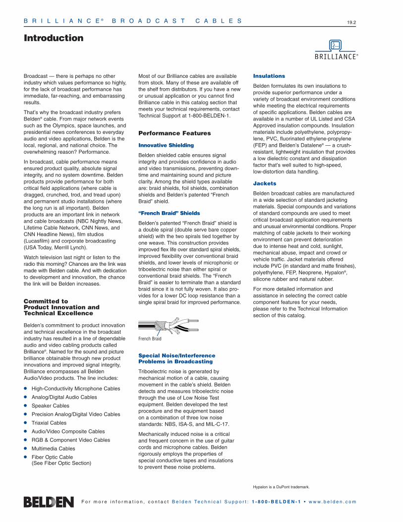
B R I L L I A N C E ® B R O A D C A S T C A B L E S 19.2
Introduction
Broadcast — there is perhaps no otherindustry which values performance so highly,for the lack of broadcast performance hasimmediate, far-reaching, and embarrassingresults.
That’s why the broadcast industry prefersBelden® cable. From major network eventssuch as the Olympics, space launches, andpresidential news conferences to everydayaudio and video applications, Belden is thelocal, regional, and national choice. Theoverwhelming reason? Performance.
In broadcast, cable performance meansensured product quality, absolute signalintegrity, and no system downtime. Beldenproducts provide performance for both critical field applications (where cable isdragged, crunched, trod, and tread upon)and permanent studio installations (wherethe long run is all important). Belden products are an important link in networkand cable broadcasts (NBC Nightly News,Lifetime Cable Network, CNN News, andCNN Headline News), film studios(Lucasfilm) and corporate broadcasting(USA Today, Merrill Lynch).
Watch television last night or listen to theradio this morning? Chances are the link wasmade with Belden cable. And with dedicationto development and innovation, the chancethe link will be Belden increases.
Committed to Product Innovation andTechnical Excellence
Belden’s commitment to product innovationand technical excellence in the broadcastindustry has resulted in a line of dependableaudio and video cabling products calledBrilliance®. Named for the sound and picturebrilliance obtainable through new productinnovations and improved signal integrity,Brilliance encompasses all BeldenAudio/Video products. The line includes:
High-Conductivity Microphone Cables
Analog/Digital Audio Cables
Speaker Cables
Precision Analog/Digital Video Cables
Triaxial Cables
Audio/Video Composite Cables
RGB & Component Video Cables
Multimedia Cables
Fiber Optic Cable(See Fiber Optic Section)
Most of our Brilliance cables are availablefrom stock. Many of these are available offthe shelf from distributors. If you have a newor unusual application or you cannot findBrilliance cable in this catalog section thatmeets your technical requirements, contactTechnical Support at 1-800-BELDEN-1.
Performance Features
Innovative Shielding
Belden shielded cable ensures signalintegrity and provides confidence in audioand video transmissions, preventing down-time and maintaining sound and pictureclarity. Among the shield types availableare: braid shields, foil shields, combinationshields and Belden’s patented “FrenchBraid” shield.
“French Braid” Shields
Belden’s patented “French Braid” shield isa double spiral (double serve bare coppershield) with the two spirals tied together byone weave. This construction providesimproved flex life over standard spiral shields,improved flexibility over conventional braidshields, and lower levels of microphonic ortriboelectric noise than either spiral or conventional braid shields. The “FrenchBraid” is easier to terminate than a standardbraid since it is not fully woven. It also pro-vides for a lower DC loop resistance than asingle spiral braid for improved performance.
Special Noise/Interference Problems in Broadcasting
Triboelectric noise is generated by mechanical motion of a cable, causingmovement in the cable’s shield. Beldendetects and measures triboelectric noisethrough the use of Low Noise Test equipment. Belden developed the test procedure and the equipment based on a combination of three low noise standards: NBS, ISA-S, and MIL-C-17.
Mechanically induced noise is a critical and frequent concern in the use of guitarcords and microphone cables. Belden rigorously employs the properties of special conductive tapes and insulations to prevent these noise problems.
Insulations
Belden formulates its own insulations toprovide superior performance under a variety of broadcast environment conditionswhile meeting the electrical requirements of specific applications. Belden cables areavailable in a number of UL Listed and CSAApproved insulation compounds. Insulationmaterials include polyethylene, polypropy-lene, PVC, fluorinated ethylene-propylene(FEP) and Belden’s Datalene® — a crush-resistant, lightweight insulation that providesa low dielectric constant and dissipationfactor that’s well suited to high-speed, low-distortion data handling.
Jackets
Belden broadcast cables are manufacturedin a wide selection of standard jacketingmaterials. Special compounds and variationsof standard compounds are used to meetcritical broadcast application requirementsand unusual environmental conditions. Propermatching of cable jackets to their workingenvironment can prevent deterioration due to intense heat and cold, sunlight,mechanical abuse, impact and crowd orvehicle traffic. Jacket materials offeredinclude PVC (in standard and matte finishes),polyethylene, FEP, Neoprene, Hypalon®, silicone rubber and natural rubber.
For more detailed information and assistance in selecting the correct cablecomponent features for your needs, please refer to the Technical Information section of this catalog.
Hypalon is a DuPont trademark.
French Braid
F o r m o r e i n f o r m a t i o n , c o n t a c t B e l d e n Te c h n i c a l S u p p o r t : 1 - 8 0 0 - B E L D E N - 1 • w w w . b e l d e n . c o m

B R I L L I A N C E ® B R O A D C A S T C A B L E S 19.3
Microphone and Musical Instrument CableOverview
19•
Brill
ianc
e®Br
oadc
ast
F o r m o r e i n f o r m a t i o n , c o n t a c t B e l d e n Te c h n i c a l S u p p o r t : 1 - 8 0 0 - B E L D E N - 1 • w w w . b e l d e n . c o m
Flexible Microphone Cables
Belden® microphone cable is used for connecting low level micro-phones or musical instruments. Key properties of microphone (MIC)cable are ruggedness, flexibility, flex life and interference immunity.
MIC cable constructions utilize either 1-, 2-, 3- or 4-conductor configurations. Cable selection depends on whether the MIC orinstrument is of a high- or low-impedance design. High-impedanceMICs require unbalanced single conductor (coaxial) cables whilelow-impedance MICs utilize balanced 2-, 3-, or 4-conductor (quad)designs. Quad MIC cables are connected by attaching the twowhite conductors to one pin and two blue conductors to the other pinin a balanced-line XLR type connector. Besides the common-moderejection of a standard balanced line, this gives common-mode rejection at each pin, greatly reducing noise and interference.
High-conductivity Copper
All Belden microphone cables with bare copper conductors utilize onlyhigh-conductivity copper produced by a process called ElectrolyticTough Pitch (ETP). This refining process produces a copper conductor that is 99.95% pure copper resulting in high-conductivityper ASTM B115. The high purity obtained from ETP copper resultsin microphone cable performance that is comparable to that of oxygen-free copper cables.
Plastic cables recommended for: Lower capacitance, lower loss, greater ozone and oil resistance, lighter weight, smaller diameter.
Rubber cables recommended for: Greater abrasion and impact resistance and extra limpness so the cable will lie flat on stage or on studio floors.
Four-Conductor Star Quad Low-Impedance Cables
Quad connection scheme: The two blue wires (or wires directlyopposite one another) are connected together to form one conductor, and similarly the two white wires (or remaining wires) are connected together to form the second conductor.
Conductors joined in this manner lower the possibility of induced noise.

B R I L L I A N C E ® B R O A D C A S T C A B L E S
25 AWG Stranded (7x33) Composite Copper Conductor • (3) Strands TC, (4) Strands TCCS • TC Spiral Shield (90% Coverage)
PVC Insulation • Matte Gray PVC Jacket 1000 VDC, 60°C 9396 — 1 N/A 250 76.2 2.8 1.3 .018 .46 .017 .43 .100 2.54 — — 75 246
25 AWG Stranded (7x33) Composite Copper Conductor† • Rayon Braid + TC Braid Shield (80% Coverage) • Cotton Serve
EPDM Rubber Insulation • Cotton Serve • Black EPDM Rubber Jacket3000 VDC, 60°C 8410 — 1 N/A 500 152.4 18.5 8.4 .058 1.47 .024 .61 .245 6.22 — — 33 108
20 AWG Stranded (27x34) High-conductivity TC Conductor • Conductive Textile (100%) plus TC Spiral Shields (95% Coverage) • Paper Tape
EPDM Rubber Insulation • Black Neoprene Jacket60°C 9394 — 1 N/A 1000 304.8 26.0 11.8 .030 .76 .033 .84 .190 4.83 — — 55 180
20 AWG Stranded (26x34) High-conductivity TC Conductor • Conductive Textile (100%) plus TC Spiral Shields (75% Coverage) • Paper Tape
EPDM Rubber Insulation • Black Neoprene Jacket60°C 9778 — 1 N/A 1000 304.8 39.0 17.7 .040 1.02 .050 1.27 .235 5.97 — — 45 148
18 AWG Stranded (41x34) High-conductivity TC Conductor • Conductive Textile (100%) plus TC Spiral Shields (68% Coverage) • Paper Tape
EPDM Rubber Insulation • Black Neoprene Jacket600V RMS, 60°C 9395 — 1 N/A 1000 304.8 38.0 17.2 .045 1.14 .034 .86 .235 5.97 — — 55 180
EPDM = Ethylene Propylene Diene Monomer • TC = Tinned Copper • TCCS = Tinned Copper-covered Steel
*Capacitance between conductors.**Capacitance between center conductor and outer shield.†(3) Strands TC, (4) Strands TCCS.
Microphone and Musical Instrument CableSingle-Conductor, High-Impedance CablesHigh-Conductivity Copper
19.4
F o r m o r e i n f o r m a t i o n , c o n t a c t B e l d e n Te c h n i c a l S u p p o r t : 1 - 8 0 0 - B E L D E N - 1 • w w w . b e l d e n . c o m
UL NEC/C(UL) CEC
Type
Part No.
No.of
Cond. Ft. m
Standard Lengths StandardUnit Weight
Lbs. kg
InsulationThickness
Inch mmDescription Color
Code
JacketThickness
Inch mm
Nominal OD
Inch mm
Nominal Capacitance
*pF/Ft.
*pF/m
**pF/Ft.
**pF/m

B R I L L I A N C E ® B R O A D C A S T C A B L E S 19.5
19•
Brill
ianc
e®Br
oadc
ast
24 AWG Stranded (105x44) High-conductivity Bare Copper Conductors† • Double Bare Copper Spiral Shield (97% Coverage)
PVC Insulation • Matte Black PVC Jacket300V RMS 80°C 9397 — 2 White, 500 152.4 12.0 5.5 .012 .30 .031 .79 .176 4.47 47 154 86 283
Green 1000 304.8 24.0 10.9
24 AWG Stranded (45x40) TC Alloy Conductors† • Conductive Textile Wrap (100% Coverage) • TC Braid Shield (56% Coverage) • Cotton Spiral
EPDM Rubber Insulation • Black EPDM Jacket300V RMS 90°C 8413 — 2 White, 100 30.5 2.3 1.0 .016 .41 .017 .43 .199 5.05 30 98 55 180
Black U-500 U-152.4 13.0 5.9500 152.4 11.5 5.2
24 AWG Stranded (45x40) BC Alloy Conductors† • Conductive Textile Wrap (100% Coverage) • TC Braid Shield (65% Coverage) • Cotton Spiral
EPDM Rubber Insulation • Brown EPDM Jacket300V RMS 90°C 9399 — 2 Blue, 500 152.4 12.5 5.7 .016 .41 .020 .51 .200 5.08 30 98 55 180
Red
24 AWG Stranded (42x40) High-conductivity BC Conductors† • TC “French Braid” Shield (95% Coverage) • BC Drain Wire
Datalene® Insulation • Matte PVC Jacket (Available in Red, Yellow, Green, Blue, Gray or Black)
Digital MIC Cable 1800F NEC: 2 Black, 500 152.4 12.0 5.5 .017 .43 .037 .94 .211 5.36 12 39 26 85High-Flex 110 Ohm CL2R Red U-1000 U-304.8 26.0 11.8300V RMS 60°C AES/EBU 1000 304.8 24.0 10.9
500 ft. and 1000 ft. put-ups available in Black only.
24 AWG Stranded (42x40) High-conductivity BC Conductors† • Double Bare Copper Spiral Shield (95% Coverage)
PVC Insulation • PVC Inner Jacket • Matte PVC Outer Jacket (Available in Red, Yellow, Green, Blue or Black)
100V RMS 60°C 1812A — 2 Brown, 328 100.0 9.8 4.5 .012 .30 .037 .94 .213 5.41 33 108 54 177White 1000 304.8 31.0 14.1
328 ft. put-up not available in Green.
BC = Bare Copper • EPDM = Ethylene Propylene Diene Monomer • TC = Tinned Copper
*Capacitance between conductors.**Capacitance between one conductor and other conductors connected to shield.†Conductors cabled with fillers.
Not RoHS compliant at time of printing. Please check with Belden Technical Support for current compliance information at 1-800-BELDEN-1.
Datalene insulation features include a low dielectric constant and a low dissipation factor for high-speed, low-distortion data handling. Physical properties include good crush resistance and light weight.
Microphone and Musical Instrument CableTwo-Conductor, Low-Impedance CablesHigh-Conductivity Copper
French Braid
F o r m o r e i n f o r m a t i o n , c o n t a c t B e l d e n Te c h n i c a l S u p p o r t : 1 - 8 0 0 - B E L D E N - 1 • w w w . b e l d e n . c o m
UL NEC/C(UL) CEC
Type
Part No.
No.of
Cond. Ft. m
Standard Lengths StandardUnit Weight
Lbs. kg
InsulationThickness
Inch mmDescription Color
Code
JacketThickness
Inch mm
Nominal OD
Inch mm
Nominal Capacitance
*pF/Ft.
*pF/m
**pF/Ft.
**pF/m

24 AWG Stranded (19x36) HC TC Conductors • Twisted Pair • Noise Reducing Tape • Beldfoil® Shield (100% Coverage) • TC Drain Wire
High-density Polyethylene Insulation • Black PVC Jacket200V RMS 75°C 9452 — 2 Black, U-500 U-152.4 6.5 3.0 .008 .20 .020 .51 .135 3.43 30 98 58 190
Red 500 152.4 6.0 2.7U-1000 U-304.8 12.0 5.5
1000 304.8 12.0 5.5
24 AWG Stranded (27x38) High-conductivity Bare Copper Conductors • Bare Copper Spiral Shield (92% Coverage)
PVC Insulation • Black Matte PVC Jacket100V RMS 60°C 1813A — 2 Red, 328 100.0 10.2 4.6 .017 .43 .055 1.40 .236 5.99 33 108 61 200
Blue 1000 304.8 31.0 14.1
22 AWG Stranded (16x34) High-conductivity Tinned Copper Conductors • Cotton Braid • Double TC Braid Shield (85% Coverage)
Polyethylene Insulation • Chrome PVC Jacket1000V RMS 80°C 8422 — 2 Clear, 500 152.4 15.0 6.8 .021 .53 .022 .56 .231 5.87 18 59 32 105
Black U-1000 U-304.8 31.0 14.11000 304.8 33.0 15.0
20 AWG Stranded (26x34) High-conductivity TC Conductors • Rayon Braid • TC Braid Shield (85% Coverage) • Cotton Wrap
EPDM Rubber Insulation • EPDM Jacket (Available in Black, Red, Yellow or Blue)
600V RMS 90°C 8412 — 2 White, 100 30.5 5.2 2.4 .023 .58 .035 .89 .262 6.65 30 98 55 180Black 250 76.2 12.0 5.5
U-500 U-152.4 24.0 10.9500 152.4 22.0 10.0
U-1000 U-304.8 46.0 20.9Red, Yellow or Blue available in 1000 ft. put-up only. 1000 304.8 47.0 21.4
EPDM Rubber Insulation • Brown Hypalon® Jacket600V RMS 60°C 8402 — 2 White, 500 152.4 25.0 11.3 .023 .58 .035 .89 .263 6.68 30 98 55 180VW-1 Black U-1000 U-304.8 52.0 23.6
18 AWG Stranded (41x34) High-conductivity TC Conductors • Rayon Braid • TC Braid Shield (85% Coverage) • Cotton Wrap
EPDM Rubber Insulation • Black Neoprene Jacket600V RMS 60°C 8428 — 2 White, 100 30.5 6.3 2.8 .023 .58 .030 .76 .290 7.37 35 115 60 197
Black U-500 U-152.4 29.0 13.2500 152.4 28.0 12.7
1000 304.8 59.0 26.8
16 AWG Stranded (65x34) High-conductivity TC Conductors • Rayon Braid • Paper Wrap • TC Braid Shield (85% Coverage) • Cotton Wrap
EPDM Rubber Insulation • Brown Hypalon® Heavy-duty Jacket600V RMS 60°C 8408 — 2 Black, 500 152.4 50.0 22.7 .037 .94 .040 1.02 .380 9.65 30 98 55 180VW-1 White
BC = Bare Copper • EPDM = Ethylene Propylene Diene Monomer • HC = High-conductivity • TC = Tinned Copper
*Capacitance between conductors. **Capacitance between one conductor and other conductors connected to shield.
Microphone and Musical Instrument CableTwo-Conductor, Low-Impedance CablesHigh-Conductivity Copper
B R I L L I A N C E ® B R O A D C A S T C A B L E S 19.6
F o r m o r e i n f o r m a t i o n , c o n t a c t B e l d e n Te c h n i c a l S u p p o r t : 1 - 8 0 0 - B E L D E N - 1 • w w w . b e l d e n . c o m
UL NEC/C(UL) CEC
Type
Part No.
No.of
Cond. Ft. m
Standard Lengths StandardUnit Weight
Lbs. kg
InsulationThickness
Inch mmDescription Color
Code
JacketThickness
Inch mm
Nominal OD
Inch mm
Nominal Capacitance
*pF/Ft.
*pF/m
**pF/Ft.
**pF/m
Shorting Fold
Hypalon is a DuPont trademark.

B R I L L I A N C E ® B R O A D C A S T C A B L E S 19.7
19•
Brill
ianc
e®Br
oadc
ast
F o r m o r e i n f o r m a t i o n , c o n t a c t B e l d e n Te c h n i c a l S u p p o r t : 1 - 8 0 0 - B E L D E N - 1 • w w w . b e l d e n . c o m
Microphone and Musical Instrument CableThree-Conductor, Low-Impedance CablesHigh-Conductivity Copper
24 AWG Stranded (105x44) High-conductivity Bare Copper Conductors • Double Bare Copper Spiral Shield (97% Coverage)
PVC Insulation • Matte Black PVC Jacket300V RMS 80°C 9398 — 3 White, 1000 304.8 25.0 11.4 .012 .30 .030 .76 .185 4.70 40 131 110 361
Green,Brown
24 AWG Stranded (45x40) TC Alloy Conductors • Conductive Textile Wrap (100% Coverage) • TC Braid Shield (60% Coverage)
EPDM Rubber Insulation • Black EPDM Rubber Jacket300V 90°C 8406 — 3 Black, 100 30.5 3.0 1.4 .016 .41 .025 .64 .223 5.66 30 98 55 180
Red, 500 152.4 15.0 6.8White
24 AWG Stranded (19x32) High-conductivity Tinned Copper Conductors • Rayon Braid • TC Braid Shield (89% Coverage)
Polyethylene Insulation • Chrome PVC Jacket600V RMS 80°C 8403 — 3 Clear, 500 152.4 20.5 9.3 .016 .41 .033 .84 .244 6.20 25 82 45 148VW-1 Black, 1000 304.8 45.0 20.5
Red
20 AWG Stranded (26x34) High-conductivity TC Conductors • Rayon Braid • TC Braid Shield (85% Coverage) • Cotton Wrap
EPDM Rubber Insulation • Black EPDM Jacket600V RMS 90°C 8423 — 3 White, 100 30.5 6.0 2.7 .023 .58 .040 1.02 .272 6.91 30 98 55 180
Black, 500 152.4 26.0 11.8Red 1000 304.8 56.0 25.5
EPDM = Ethylene Propylene Diene Monomer • TC = Tinned Copper
*Capacitance between conductors.**Capacitance between one conductor and other conductors connected to shield.
Not RoHS compliant at time of printing. Please check with Belden Technical Support for current compliance information at 1-800-BELDEN-1.
UL NEC/C(UL) CEC
Type
Part No.
No.of
Cond. Ft. m
Standard Lengths StandardUnit Weight
Lbs. kg
InsulationThickness
Inch mmDescription Color
Code
JacketThickness
Inch mm
Nominal OD
Inch mm
Nominal Capacitance
*pF/Ft.
*pF/m
**pF/Ft.
**pF/m

Microphone and Musical Instrument CableFour-Conductor Star Quad, Low-Impedance Cables†
High-Conductivity Copper
B R I L L I A N C E ® B R O A D C A S T C A B L E S 19.8
F o r m o r e i n f o r m a t i o n , c o n t a c t B e l d e n Te c h n i c a l S u p p o r t : 1 - 8 0 0 - B E L D E N - 1 • w w w . b e l d e n . c o m
UL NEC/C(UL) CEC
Type
Part No.
No.of
Cond. Ft. m
Standard Lengths StandardUnit Weight
Lbs. kg
InsulationThickness
Inch mmDescription Color
Code
JacketThickness
Inch mm
Nominal OD
Inch mm
Nominal Capacitance
*pF/Ft.
*pF/m
**pF/Ft.
**pF/m
2/c 25 AWG equivalent DCR when connected to a 3-pin XLR.
28 AWG Stranded (19x40) High-conductivity Silver-plated Copper Alloy Conductors • Tinned Copper Braid Shield (78% Coverage)
Polypropylene Insulation • Matte PVC Jacket (Available in Red, Yellow, Blue, Beige or Black)
Mini Star Quad 1804A — 4 Blue/White, 100 30.5 1.6 0.7 .006 .15 .014 .36 .115 2.92 40 131 60 197100V RMS 60°C White/Blue 500 152.4 4.5 2.0
100 ft. put-up available in Black only.May contain more than one piece. Min. length of any one piece is 50 ft.One Blue conductor and one White conductor are striped for use in MIDI and other four conductor applications.
26 AWG Stranded (30x40) High-conductivity BC Conductors • TC “French Braid” Shield (95% Coverage) • BC Drain Wire
Polyethylene Insulation • Matte PVC Jacket (Available in Red, Green, Yellow, Blue, Gray or Black)
100V RMS 60°C 1172A — 4 Blue/White, 500 152.4 13.5 6.1 .011 .28 .030 .76 .190 4.83 39 128 57 187White/Blue 1000 304.8 25.0 11.3
500 ft. put-up available in Black only.One Blue conductor and one White conductor are striped for use in MIDI and other four conductor applications.
24 AWG Stranded (42x40) High-conductivity Bare Copper Conductors • Tinned Copper Braid Shield (95% Coverage)
Polyethylene Insulation • Matte PVC Jacket (Available in Red, Green, Yellow, Blue, Gray or Black)
100V RMS 75°C 1192A — 4 Blue/White, 100 30.5 4.1 1.8 .016 .41 .045 1.14 .245 6.22 39 128 57 187White/Blue 500 152.4 16.5 7.5
1000 304.8 37.0 16.8
100 ft. put-up available in Black only. 500 ft. put-up available in Blue or Black only.One Blue conductor and one White conductor are striped for use in MIDI and other four conductor applications.
20 AWG Stranded (19x32) High-conductivity Tinned Copper Conductors • Rayon Braid • Tinned Copper Braid Shield (85% Coverage)
Polyethylene Insulation • Chrome PVC JacketUL AWM Style 2094 8404 — 4 Clear, 100 30.5 5.4 2.4 .016 .41 .032 .81 .252 6.40 23 75 49 161(300V RMS 60°C) Black, 500 152.4 23.0 10.4VW-1 Red, U-1000 U-304.8 48.0 21.8
Green 1000 304.8 49.0 22.3
20 AWG Stranded (26x34) High-conductivity Tinned Copper Conductors • Rayon Braid • TC Braid Shield (85% Coverage) • Cotton Wrap
EPDM Rubber Insulation • Black EPDM Rubber Jacket600V RMS 90°C 8424 — 4 Black, 100 30.5 6.8 3.1 .023 .58 .036 .91 .294 7.47 47 154 59 194
White, 250 76.2 15.3 6.9Red, U-500 U-152.4 32.0 14.5
Green 500 152.4 30.5 13.81000 304.8 64.0 29.1
16 AWG Stranded (65x34) High-conductivity Tinned Copper Conductors • Rayon Braid • TC Braid Shield (85% Coverage) • Cotton Wrap
EPDM Rubber Insulation • Black Neoprene Jacket600V RMS 60°C 8407 — 4 Black, 100 30.5 11.3 5.1 .031 .79 .043 1.09 .416 10.57 30 98 66 216VW-1 White, 250 76.2 28.3 12.8
Red,Green
BC = Bare Copper • EPDM = Ethylene Propylene Diene Monomer • TC = Tinned Copper
*Capacitance between conductors. **Nom. capacitance between conductors in a Quad configuration.
Not RoHS compliant at time of printing. Please check with Belden Technical Support for current compliance information at 1-800-BELDEN-1.
†Quad connection scheme: The two blue wires (or wires directly opposite one another) areconnected together to form one conductor, and similarly the two white wires (or remainingwires) are connected together to form the second conductor.
French Braid2/c 23 AWG equivalent DCR when connected to a 3-pin XLR.
2/c 21 AWG equivalent DCR when connected to a 3-pin XLR.
2/c 17 AWG equivalent DCR when connected to a 3-pin XLR.
2/c 17 AWG equivalent DCR when connected to a 3-pin XLR.
2/c 13 AWG equivalent DCR when connected to a 3-pin XLR.

B R I L L I A N C E ® B R O A D C A S T C A B L E S 19.9
19•
Brill
ianc
e®Br
oadc
ast
F o r m o r e i n f o r m a t i o n , c o n t a c t B e l d e n Te c h n i c a l S u p p o r t : 1 - 8 0 0 - B E L D E N - 1 • w w w . b e l d e n . c o m
Line Level Analog Audio CableSingle-Pair Cables
24 AWG Stranded (7x32) TC Conductors • Twisted Pair • Overall Beldfoil Shield (100% Coverage) • 24 AWG Stranded TC Drain Wire
Polypropylene Insulation • PVC Jacket (Available in Brown, Red, Green, Lt. Blue, Purple, Gray, White or Black)
300V RMS 60°C 1883A NEC: 1 Black, U-1000 U-304.8 11.0 5.0 .008 .20 .020 .51 .123 3.12 31 102 58 190CMR Red 1000 304.8 11.0 5.0CEC:
CMG FT4
1000 ft. put-up available in Gray only.Jacket and shield are bonded so both can be removed with automatic stripping equipment.
Polyolefin Insulation • Black Matte PVC JacketHigh-Flex 1508A NEC: 1 Black, 500 152.4 6.5 2.9 .008 .20 .024 .61 .131 3.33 31 102 58 190300V RMS 60°C CM Red 1000 304.8 11.0 5.0
CEC:CM
Jacket and shield are bonded so both can be removed with automatic stripping equipment.
24 AWG Stranded (7x32) TC Conductors • Twisted Pair • Overall Beldfoil Shield (100% Coverage)†† • 24 AWG Stranded TC Drain Wire
Polyethylene Insulation • Chrome PVC JacketLow-Capacitance 8641 NEC: 1 Black, 100 30.5 2.3 1.0 .016 .41 .025 .64 .168 4.27 22 72 42 138UL AWM Style 2092 CM Clear U-500 U-152.4 7.5 3.4(300V RMS 60°C) CEC: 500 152.4 7.0 3.2
CM U-1000 U-304.8 14.0 6.41000 304.8 14.0 6.42000 609.6 28.0 12.7
Plenum • FEP Insulation • Red FEP Jacket300V RMS 200°C, Non-conduit 88641 NEC: 1 Black, 100 30.5 2.4 1.1 .006 .15 .014 .36 .106 2.69 31 102 59 194
CMP Red 500 † 152.4 6.0 2.7CEC: 1000 † 304.8 9.0 4.1
CMP FT6
Plenum • FEP Insulation • Natural Flamarrest® Jacket300V RMS 60°C, Non-conduit 82641 NEC: 1 Black, U-1000 †† U-304.8 9.0 4.1 .006 .15 .014 .36 .106 2.69 31 102 59 194
CMP Red 1000 †† 304.8 8.0 3.6CEC:
CMP FT6
FEP = Fluorinated Ethylene Propylene • TC = Tinned Copper
*Capacitance between conductors. **Capacitance between one conductor and other conductors connected to shield.†Spools and/or UnReel® cartons are one piece, but length may vary ±10% for spools and ±5% for UnReel from length shown. ††Length may vary ±10% for UnReel.
For Plenum versions of 8641, see 88641 or 82641.
For cross-connect use with 1408R (et al.) Snake Cables, see page 19.18.
For cross-connect use with 1408R (et al.) Snake Cables, see page 19.18.
Z-Fold®
UL NEC/C(UL) CEC
Type
Part No.
No.of
Pairs Ft. m
Standard Lengths StandardUnit Weight
Lbs. kg
InsulationThickness
Inch mmDescription Color
Code
JacketThickness
Inch mm
Nominal OD
Inch mm
Nominal Capacitance
*pF/Ft.
*pF/m
**pF/Ft.
**pF/m
Belden analog audio cables are used for connecting line level audioequipment in either permanent or semi-permanent installations.They consist of one or two individually foil-shielded, twisted pairs.Once installed, they are not intended to be moved while in service.For cables that are in motion during use, refer to the Microphoneand Musical Instrument Cable section in this catalog.
Belden’s analog audio cable offering consists of a selection of designs to handle a variety of audio applications. Belden part
no. 8451 utilizes a paper tape separator to facilitate easy long lengthjacket stripping. Part no. 9451 comes with a bonded Beldfoil® shield so that the shield and jacket strip simultaneously. A special mattePVC jacket material is employed on part no. 1508A making it a highlyflexible construction. Double pair cables are available in a roundconstruction (part no. 8723) or in a ZIP cord style (part no. 1504A) for easy separation in two-channel or stereo hook-ups.

22 AWG Stranded (7x30) TC Conductors • Twisted Pair • Overall Beldfoil® Shield (100% Coverage) • 24 AWG Stranded TC Drain Wire
Polypropylene Insulation • PVC Jacket (Available in Brown, Red, Orange, Yellow, Green, Blue, Purple, Gray, White or Black)
300V RMS 60°C 1266A NEC: 1 Black, U-1000 U-304.8 15.0 6.8 .010 .25 .020 .51 .143 3.63 30 99 54 177CM Red 1000 304.8 15.0 6.8CEC:CM
1000 ft. put-up available in Black only. Unique design features lower capacitance and greater flexibility than standard audio pair constructions.
PVC Insulation • PVC Jacket (Available in Brown, Red, Orange, Yellow, Green, Blue, Purple, Gray, White or Black)
300V RMS 90°C 1503A NEC: 1 Black, U-1000 U-304.8 16.0 7.3 .010 .25 .020 .51 .142 3.61 53 174 97 318CM RedCEC:CM
22 AWG Stranded (7x30) TC Conductors • Twisted Pair • Overall Beldfoil Shield (100% Coverage) • 22 AWG Stranded TC Drain Wire
Polypropylene Insulation • Paper Wrap • Gray or Black PVC Jacket300V RMS 75°C 8451 NEC: 1 Black, 100 30.5 2.3 1.1 .008 .20 .020 .51 .138 3.51 34 111 67 220
CMR Red U-500 U-152.4 8.5 3.9CEC: 500 152.4 8.0 3.6
CMG FT4 U-1000 U-304.8 16.0 7.31000 304.8 16.0 7.3
100 ft. put-up available in Black only.Unique paper separator facilitates jacket stripping.
Polypropylene Insulation • PVC Jacket (Available in Brown, Red, Orange, Yellow, Green, Blue, Purple, Gray, White or Black)
300V RMS 75°C 9451 NEC: 1 Black, U-500 U-152.4 8.5 3.9 .008 .20 .020 .51 .135 3.43 35 115 67 220CMR Red 500 152.4 8.0 3.6CEC: T-1000 T-304.8 18.0 8.2
CMG FT4 U-1000 U-304.8 15.0 6.85000 1524.0 75.0 34.0
U-500 ft., 500 ft. and T-1000 ft. put-ups available in Gray only. The jacket and shield are bonded so both can be removed on automatic stripping equipment. Drain wire is inside foil shield.
Polypropylene Insulation • Black Low-Smoke, Zero-Halogen Jacket LSZH and ABS Type Approved 9451SB NEC: 1 Black, 1000 304.8 20.0 9.1 .008 .20 .032 .81 .160 4.06 35 114 67 220300V RMS 105°C u CMG-LS Red
CEC:CMG-LS FT4
Limited Smoke
The jacket and shield are bonded so both can be removed on automatic stripping equipment. Drain wire is inside foil shield.
Plenum • FEP Insulation • Flamarrest® Jacket (Brown, Red, Orange, Yellow, Green, Blue, Purple, Gray, White or Black)
300V RMS 60°C 9451P NEC: 1 Black, U-1000 U-304.8 16.0 7.3 .007 .18 .017 .43 .127 3.23 35 115 67 220u CMP Red 5000 1524.0 75.0 34.0
CEC:CMP FT6
The jacket and shield are bonded so both can be removed on automatic stripping equipment. Drain wire is inside foil shield.
22 AWG Solid Tinned Copper Conductors • Twisted Pair • Overall Beldfoil Shield (100% Coverage) • 22 AWG Solid TC Drain Wire
Polypropylene Insulation • Gray or Black PVC Jacket300V RMS 75°C 8450 NEC: 1 Black, U-500 U-152.4 7.5 3.4 .007 .18 .018 .46 .118 3.00 40 131 76 249
CM Red U-1000 U-304.8 14.0 6.4CEC: 1000 304.8 13.0 5.9CM
U-500 ft. and U-1000 ft. put-ups available in Black only.Belden’s Miniature Type Broadcast Audio and Instrumentation Cables occupy 1/2 to 2/3 less space than standard cables.
FEP = Fluorinated Ethylene Propylene • TC = Tinned Copper
*Capacitance between conductors.**Capacitance between one conductor and other conductors connected to shield.
Line Level Analog Audio CableSingle-Pair Cables
B R I L L I A N C E ® B R O A D C A S T C A B L E S 19.10
F o r m o r e i n f o r m a t i o n , c o n t a c t B e l d e n Te c h n i c a l S u p p o r t : 1 - 8 0 0 - B E L D E N - 1 • w w w . b e l d e n . c o m
Z-Fold®
Z-Fold®
UL NEC/C(UL) CEC
Type
Part No.
No.of
Pairs Ft. m
Standard Lengths StandardUnit Weight
Lbs. kg
InsulationThickness
Inch mmDescription Color
Code
JacketThickness
Inch mm
Nominal OD
Inch mm
Nominal Capacitance
*pF/Ft.
*pF/m
**pF/Ft.
**pF/m
For cross-connect use with 1814R (et al.) Snake Cables, see page 19.21
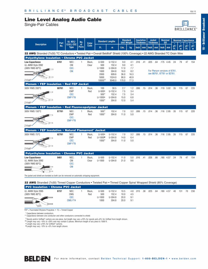
B R I L L I A N C E ® B R O A D C A S T C A B L E S 19.11
19•
Brill
ianc
e®Br
oadc
ast
F o r m o r e i n f o r m a t i o n , c o n t a c t B e l d e n Te c h n i c a l S u p p o r t : 1 - 8 0 0 - B E L D E N - 1 • w w w . b e l d e n . c o m
Line Level Analog Audio CableSingle-Pair Cables
22 AWG Stranded (7x30) TC Conductors • Twisted Pair • Overall Beldfoil® Shield (100% Coverage) • 22 AWG Stranded TC Drain Wire
Polyethylene Insulation • Chrome PVC JacketLow-Capacitance 8761 NEC: 1 Black, U-500 U-152.4 9.0 4.1 .016 .41 .025 .64 .175 4.45 24 79 47 154UL AWM Style 2092 CM Clear 500 152.4 9.0 4.1(300V RMS 60°C) CEC: U-1000 U-304.8 17.0 7.7
CM 1000 304.8 18.0 8.22000 609.6 36.0 16.35000 1524.0 90.0 40.9
10000†† 3048.0 170.0 77.3
Plenum • FEP Insulation • Red FEP Jacket300V RMS 200°C 88761 NEC: 1 Black, 100 30.5 2.7 1.2 .006 .15 .014 .36 .119 3.02 35 115 67 220
CMP Red U-500 U-152.4 7.5 3.4CEC: 500† 152.4 7.5 3.4
CMP FT6 U-1000 U-304.8 15.0 6.81000† 304.8 12.0 5.4
Plenum • FEP Insulation • Red Fluorocopolymer Jacket300V RMS 150°C 87761 NEC: 1 Black, 500† 152.4 7.0 3.2 .006 .15 .014 .36 .116 2.95 35 115 67 220
CMP Red 1000† 304.8 11.0 5.0CEC:
CMP FT6
Plenum • FEP Insulation • Natural Flamarrest® Jacket300V RMS 75°C 82761 NEC: 1 Black, U-500 U-152.4 7.0 3.2 .006 .15 .014 .36 .116 2.95 35 115 67 220
CMP Red U-1000 U-304.8 14.0 6.4CEC: 1000† 304.8 11.0 5.0
CMP FT6
Polyethylene Insulation • Chrome PVC JacketLow-Capacitance 9461 NEC: 1 Black, U-500 U-152.4 11.0 5.0 .016 .41 .026 .66 .180 4.57 24 79 47 154UL AWM Style 2092 CM Clear U-1000 U-304.8 21.0 9.6(300V RMS 60°C) CEC:
CM
The jacket and shield are bonded so both can be removed on automatic stripping equipment.
22 AWG Stranded (7x30) Tinned Copper Conductors • Twisted Pair • Tinned Copper Spiral Wrapped Shield (85% Coverage)
PVC Insulation • Chrome PVC JacketUL AWM Style 2095 8737 NEC: 1 Black, U-500 U-152.4 10.5 4.8 .015 .38 .025 .64 .180 4.57 40 131 70 230(300V RMS 80°C) CMG Red 500 152.4 10.0 4.5
CEC: U-1000 U-304.8 20.0 9.1CMG FT4 1000 304.8 20.0 9.1
FEP = Fluorinated Ethylene Propylene • TC = Tinned Copper
* Capacitance between conductors.** Capacitance between one conductor and other conductors connected to shield.
† Spools and/or UnReel® cartons are one piece, but length may vary ±10% for spools and ±5% for UnReel from length shown.†† Length may vary -10% to +20% and may contain 2 pieces. Minimum length of any piece is 1500 ft.
Length may vary ±10% for UnReel® cartons. Length may vary -10% to +5% from length shown.
Z-Fold®
For Plenum versions of 8761, see 88761, 87761 or 82761.
UL NEC/C(UL) CEC
Type
Part No.
No.of
Pairs Ft. m
Standard Lengths StandardUnit Weight
Lbs. kg
InsulationThickness
Inch mmDescription Color
Code
JacketThickness
Inch mm
Nominal OD
Inch mm
Nominal Capacitance
*pF/Ft.
*pF/m
**pF/Ft.
**pF/m
Z-Fold®
Z-Fold®
Z-Fold®
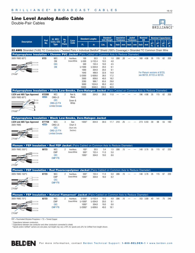
Line Level Analog Audio CableDouble-Pair Cables
B R I L L I A N C E ® B R O A D C A S T C A B L E S 19.12
F o r m o r e i n f o r m a t i o n , c o n t a c t B e l d e n Te c h n i c a l S u p p o r t : 1 - 8 0 0 - B E L D E N - 1 • w w w . b e l d e n . c o m
22 AWG Stranded (7x30) TC Conductors • Twisted Pairs • Individual Beldfoil® Shield (100% Coverage) • Stranded TC Common Drain Wire
Polypropylene Insulation • Chrome PVC Jacket (Pairs Cabled on Common Axis to Reduce Diameter)
300V RMS 60°C 8723 NEC: 2 Red/Black, 100 30.5 2.3 1.0 .008 .20 — — .160 4.06 35 115 62 203CM Green/White U-500 U-152.4 10.5 4.8CEC: 500 152.4 10.0 4.5CM U-1000 U-304.8 20.0 9.1
1000 304.8 20.0 9.11640 499.9 32.8 14.9
U-2000 U-609.6 38.0 17.22000 609.6 40.0 18.23280 999.7 65.6 29.85000 1524.0 95.0 43.2
10000 3048.0 200.0 90.9
Polypropylene Insulation • Black Low-Smoke, Zero-Halogen Jacket (Pairs Cabled on Common Axis to Reduce Diameter)
LSZH and ABS Type Approved 8723SB NEC: 2 Red & 1000 304.8 26.0 11.8 — — — — .196 4.98 35 115 62 203300V RMS 60°C u CMG-LS Black,
CEC: Green & CMG-LS FT4 White
Limited Smoke
Polypropylene Insulation • Black Low-Smoke, Zero-Halogen JacketLSZH and ABS Type Approved 8777SB NEC: 3 See 1000† 304.8 39.0 17.7 .010 .25 — — .273 6.93 30 98 55 180300V RMS u CMG-LS Chart 3
CEC: (Tech InfoCMG-LS FT4 Section)
Limited Smoke
Plenum • FEP Insulation • Red FEP Jacket (Pairs Cabled on Common Axis to Reduce Diameter)
300V RMS 200°C 88723 NEC: 2 Red/Black, 100† 30.5 3.4 1.5 .006 .15 — — .148 3.76 35 115 67 220CMP Green/White 500† 152.4 11.0 5.0CEC: 1000† 304.8 19.0 8.6
CMP FT6
Plenum • FEP Insulation • Red Fluorocopolymer Jacket (Pairs Cabled on Common Axis to Reduce Diameter)
300V RMS 150°C 87723 NEC: 2 Red/Black, 500† 152.4 11.0 5.0 .006 .15 — — .148 3.76 35 115 67 220CMP Green/White 1000† 304.8 18.0 8.2CEC:
CMP FT6
Plenum • FEP Insulation • Natural Flamarrest® Jacket (Pairs Cabled on Common Axis to Reduce Diameter)
300V RMS 75°C 82723 NEC: 2 Red/Black, U-500† U-152.4 10.5 4.8 .006 .15 — — .153 3.89 43 141 75 246CMP Green/White U-1000†† U-304.8 20.0 9.1CEC: 1000† 304.8 19.0 8.6
CMP FT6 U-2000† U-609.6 40.0 18.1
FEP = Fluorinated Ethylene Propylene • TC = Tinned Copper
*Capacitance between conductors.**Capacitance between one conductor and other conductors connected to shield.† Spools and/or UnReel® cartons are one piece, but length may vary ±10% for spools and ±5% for UnReel from length shown.
Z-Fold®
Z-Fold®
Z-Fold®
Z-Fold®
For Plenum versions of 8723,see 88723, 87723 or 82723.
UL NEC/C(UL) CEC
Type
Part No.
No.of
Pairs Ft. m
Standard Lengths StandardUnit Weight
Lbs. kg
InsulationThickness
Inch mmDescription Color
Code
JacketThickness
Inch mm
Nominal OD
Inch mm
Nominal Capacitance
*pF/Ft.
*pF/m
**pF/Ft.
**pF/m
Z-Fold®
Z-Fold®

B R I L L I A N C E ® B R O A D C A S T C A B L E S 19.13
19•
Brill
ianc
e®Br
oadc
ast
F o r m o r e i n f o r m a t i o n , c o n t a c t B e l d e n Te c h n i c a l S u p p o r t : 1 - 8 0 0 - B E L D E N - 1 • w w w . b e l d e n . c o m
Line Level Analog Audio CableSingle- and Double-Pair Cables
22 AWG Stranded (19x34) TC Conductors • Dual Twisted Pairs • Overall Beldfoil® Shield (100% Coverage) • 24 AWG Stranded TC Drain Wire
PVC Insulation • PVC Jacket in Zip-Cord Construction (Red & Green, Red & Black, Red & Purple or Red & Gray)150V RMS 60°C 1504A NEC: 2 Black, U-1000 U-304.8 32.0 14.5 .010 .25 .020 .51 .143 3.63 57 187 100 328
CM Red 2000 609.8 64.0 29.0 x xCEC: .286 7.26CM
2000 ft. put-up available in Red & Gray or Red & Green only.The jacket and shield are bonded so both can be removed on automatic stripping equipment. Drain wire is inside foil shield.
22 AWG Stranded (7x30) TC Conductors • Dual Twisted Pairs • Overall Beldfoil Shield (100% Coverage) • 22 AWG Stranded TC Drain Wire
Polyolefin Insulation • PVC Jacket in Zip-Cord Construction (Red & Green, Red & Gray, Red & Black or Red & Purple)300V RMS 105°C 9451D NEC: 2 Black, U-1000 U-304.8 29.0 13.2 .008 .20 .020 .51 .135 3.43 34 112 67 220
CMR Red 2000 620.8 62.0 28.1 x xCEC: .270 6.86
CMG FT4
2000 ft. put-up available in Red & Green only.The jacket and shield are bonded so both can be removed on automatic stripping equipment. Drain wire is inside foil shield.
Plenum • FEP Insulation • White Flamarrest® Jacket in Zip-Cord Construction300V RMS 60°C 9451DP NEC: 2 Black & 1000 304.8 24.0 10.9 .007 .18 .017 .43 .127 3.23 35 115 67 220
u CMP Red, x xCEC: Black & .269 6.83
CMP FT6 White
The jacket and shield are bonded so both can be removed on automatic stripping equipment. Drain wire is inside foil shield.
20 AWG Stranded (7x28) TC Conductors • Twisted Pair • Overall Beldfoil Shield (100% Coverage) • 20 AWG Stranded TC Drain Wire
PVC Insulation • Beige PVC JacketUL AWM Style 2464 9154 NEC: 1 Black, U-500 U-152.4 11.5 5.2 .014 .36 .031 .79 .198 5.03 60 197 100 328(300V RMS 80°C) CMG Red 500 152.4 12.0 5.5
CEC: U-1000 U-304.8 22.0 10.0CMG FT4 1000 304.8 23.0 10.5
9154 has 22 AWG stranded tinned copper drain wire.
Polyethylene Insulation • Chrome PVC JacketUL AWM Style 2092 8762 NEC: 1 Black, 100 30.5 3.2 1.5 .016 .41 .028 .71 .204 5.18 27 89 49 161(300V RMS 60°C) CM Clear 250 76.2 6.3 2.8
CEC: U-500 U-152.4 12.0 5.5CM 500 152.4 12.0 5.5
U-1000 U-304.8 23.0 10.51000 304.8 23.0 10.52000 609.6 46.0 20.9
10000 3048.0 240.0 109.1
UL AWM Style 2092 9464 NEC: 1 Black, U-500 U-152.4 17.0 7.7 .016 .41 .035 .89 .214 5.44 27 89 49 161(300V RMS 60°C) CM Clear U-1000 U-304.8 32.0 14.5
CEC:CM
The jacket and shield are bonded so both can be removed on automatic stripping equipment. Drain wire is on the inside of foil shield.
20 AWG Stranded (7x28) Tinned Copper Conductors • Twisted Pair • Tinned Copper Spiral Wrapped Shield (89% Coverage)
PVC Insulation • Chrome PVC JacketUL AWM Style 2095 8759 NEC: 1 Black, U-500 U-152.4 12.5 5.7 .016 .41 .025 .64 .199 5.05 47 154 79 259(300V RMS 80°C) CMG Red U-1000 U-304.8 24.0 10.9
CEC: 1000 304.8 25.0 11.4CMG FT4
FEP = Fluorinated Ethylene Propylene • TC = Tinned Copper
*Capacitance between conductors.**Capacitance between one conductor and other conductors connected to shield.
Z-Fold®
Shorting Fold
UL NEC/C(UL) CEC
Type
Part No.
No.of
Pairs Ft. m
Standard Lengths StandardUnit Weight
Lbs. kg
InsulationThickness
Inch mmDescription Color
Code
JacketThickness
Inch mm
Nominal OD
Inch mm
Nominal Capacitance
*pF/Ft.
*pF/m
**pF/Ft.
**pF/m

B R I L L I A N C E ® B R O A D C A S T C A B L E S 19.14
Line Level Analog Audio CableSingle-Pair Cables
F o r m o r e i n f o r m a t i o n , c o n t a c t B e l d e n Te c h n i c a l S u p p o r t : 1 - 8 0 0 - B E L D E N - 1 • w w w . b e l d e n . c o m
18 AWG Stranded (16x30) TC Conductors • Twisted Pair • Overall Beldfoil® Shield (100% Coverage) • 20 AWG Stranded TC Drain Wire
Polyethylene Insulation • Chrome PVC JacketLow-Capacitance 9460 NEC: 1 Black, U-500 U-152.4 18.5 8.4 .019 .48 .030 .76 .230 5.84 30 98 44 144UL AWM Style 2092 CM Clear U-1000 U-304.8 36.0 16.4(300V RMS 60°C) CEC:
CM
The jacket and shield are bonded so both can be removed on automatic stripping equipment. Drain wire is on the inside of foil shield.
Low-Capacitance 8760 NEC: 1 Black, 250 76.2 6.8 3.1 .019 .48 .028 .71 .222 5.64 30 98 44 144UL AWM Style 2092 CM Clear U-500 U-152.4 13.5 6.1(300V RMS 60°C) CEC: 500 152.4 13.0 5.9
CM U-1000 U-304.8 25.0 11.31000 304.8 26.0 11.82000 609.6 50.0 22.75000 1524.0 135.0 61.4
10000 3048.0 260.0 118.2
18 AWG Stranded (19x30) TC Conductors • Twisted Pair • Overall Beldfoil Shield (100% Coverage) • 20 AWG Stranded TC Drain Wire
Plenum • FEP Insulation • Red FEP Jacket300V RMS 200°C 88760 NEC: 1 Black, 100 30.5 3.7 1.7 .007 .18 .014 .36 .153 3.89 51 167 97 318
CMP Red U-500† U-152.4 12.5 5.7CEC: 500† 152.4 11.0 5.0
CMP FT6 U-1000† U-304.8 24.0 10.91000† 304.8 22.0 10.0
Plenum • FEP Insulation • Red Fluorocopolymer Jacket300V RMS 150°C 87760 NEC: 1 Black, U-500† U-152.4 12.5 5.7 .007 .18 .014 .36 .150 3.81 51 167 97 318
CMP Red 500† 152.4 10.5 4.8CEC: 1000† 304.8 21.0 9.5
CMP FT6
Plenum • FEP Insulation • Natural Flamarrest® Jacket300V RMS 75°C 82760 NEC: 1 Black, U-500† U-152.4 12.0 5.5 .007 .18 .014 .36 .150 3.81 51 167 97 318
CMP Red U-1000†† U-304.8 22.0 10.0CEC: 1000† 304.8 21.0 9.5
CMP FT6
18 AWG Stranded (7x26) Tinned Copper Conductors • Twisted Pair • Tinned Copper Spiral Wrapped Shield (85% Coverage)
PVC Insulation • Chrome PVC Jacket300V RMS 60°C 8790 NEC: 1 Red, U-500 U-152.4 17.5 7.9 .022 .56 .028 .71 .241 6.12 53 174 92 302
CMG White 500 152.4 17.0 7.7CEC: U-1000 U-304.8 33.0 15.0
CMG FT4 1000 304.8 35.0 15.9
FEP = Fluorinated Ethylene Propylene • TC = Tinned Copper
*Capacitance between conductors.**Capacitance between one conductor and other conductors connected to shield.† Spools and/or UnReel® cartons are one piece, but length may vary ±10% for spools and ±5% for UnReel from length shown.
††Spools and/or UnReel® cartons are one piece, but length may vary -0% to +10%.
Shorting Fold
Z-Fold®
Z-Fold®
Z-Fold®
For Plenum versions of 8760, see 88760, 87760 or 82760.
UL NEC/C(UL) CEC
Type
Part No.
No.of
Pairs Ft. m
Standard Lengths StandardUnit Weight
Lbs. kg
InsulationThickness
Inch mmDescription Color
Code
JacketThickness
Inch mm
Nominal OD
Inch mm
Nominal Capacitance
*pF/Ft.
*pF/m
**pF/Ft.
**pF/m

B R I L L I A N C E ® B R O A D C A S T C A B L E S 19.15
19•
Brill
ianc
e®Br
oadc
ast
F o r m o r e i n f o r m a t i o n , c o n t a c t B e l d e n Te c h n i c a l S u p p o r t : 1 - 8 0 0 - B E L D E N - 1 • w w w . b e l d e n . c o m
Line Level Analog Audio CableSingle-Pair Cables
16 AWG Stranded (19x29) Tinned Copper Conductors • Twisted Pair • Tinned Copper Spiral Wrapped Shield (85% Coverage)
PVC Insulation • Chrome PVC Jacket300V RMS 60°C 8780 NEC: 1 Black, 500 152.4 23.5 10.7 .023 .58 .030 .76 .280 7.11 57 187 98 322
CMG White U-1000 U-304.8 44.0 20.0CEC: 1000 304.8 46.0 20.9
CMG FT4
16 AWG Stranded (19x29) TC Conductors • Twisted Pair • Overall Beldfoil® Shield (100% Coverage) • 18 AWG Stranded TC Drain Wire
Polyethylene Insulation • Chrome PVC JacketLow-Capacitance 8719 NEC: 1 Black, U-500 U-152.4 24.0 10.9 .032 .81 .032 .81 .313 7.95 23 75 44 144UL AWM Style 20253 CM, CL2 Clear 500 152.4 25.5 11.6(600V RMS 80°C) CEC: U-1000 U-304.8 47.0 21.3
CM 1000 304.8 50.0 22.72000 609.6 100.0 45.55000 1524.0 245.0 111.4
10000 † 3048.0 510.0 231.3
14 AWG Stranded (19x27) TC Conductors • Twisted Pair • Overall Beldfoil Shield (100% Coverage) • 16 AWG Stranded TC Drain Wire
Polyethylene Insulation • Chrome PVC JacketLow-Capacitance 8720 NEC: 1 Black, U-500 U-152.4 34.0 15.4 .032 .81 .035 .89 .355 9.02 24 79 47 154UL AWM Style 20253 CL2 Clear 500 152.4 35.0 15.9(600V RMS 80°C) 1000 304.8 71.0 32.3
2000 609.6 138.0 62.7
12 AWG Stranded (19x25) TC Conductors • Twisted Pair • Overall Beldfoil Shield (100% Coverage) • 14 AWG Stranded TC Drain Wire
Polyethylene Insulation • Chrome PVC JacketLow-Capacitance 8718 NEC 1 Black, U-500 U-152.4 47.5 21.6 .037 .94 .040 1.02 .400 10.16 25 82 49 161UL AWM Style 20253 CL2 Clear 500 152.4 50.5 22.9(600V RMS 80°C) 1000 304.8 100.0 45.5
2000 609.6 198.0 90.0
TC = Tinned Copper
*Capacitance between conductors.**Capacitance between one conductor and other conductors connected to shield.
† Final put-up length may vary -10% to +20% from length shown. May contain 2 pieces. Minimum length of any one piece is 1500 ft.
Z-Fold®
Z-Fold®
Shorting Fold
UL NEC/C(UL) CEC
Type
Part No.
No.of
Pairs Ft. m
Standard Lengths StandardUnit Weight
Lbs. kg
InsulationThickness
Inch mmDescription Color
Code
JacketThickness
Inch mm
Nominal OD
Inch mm
Nominal Capacitance
*pF/Ft.
*pF/m
**pF/Ft.
**pF/m
Analog Multi-Pair Snake CableHigh-Flex and NEC Rated Cables
B R I L L I A N C E ® B R O A D C A S T C A B L E S 19.16
F o r m o r e i n f o r m a t i o n , c o n t a c t B e l d e n Te c h n i c a l S u p p o r t : 1 - 8 0 0 - B E L D E N - 1 • w w w . b e l d e n . c o m
Especially designed for the broadcastindustry, Belden’s full family of multi-pairaudio “Snake” cables feature options andconstruction for virtually every application.
Applications
Snake cables are used to connect multipleaudio channels in low-level (microphone)and high-level (line) componentry such asconsole board equipment for recording studios, radio television stations, post-production facilities, and sound systeminstallations. With Belden’s individuallyshielded and jacketed snakes, pairs can be split out of the overall jacket for anylength and connectorized directly withoutthe need for heat shrink tubing or costly and time-consuming preparation. 22 AWGand 24 AWG sizes are also ideal for punch down connector applications.
Numbered and Color Coded
Jacketed pairs are individually numberedand color coded (following the familiarresistor color code) for easy identification.
Low-Capacitance Design
Belden’s 1200 Series Snake Cables featurea low-capacitance design in a flexible, high-performance construction.
New “French Braid” Shield
Belden’s patented “French Braid” shield isa double spiral (double serve) bare coppershield with the two spirals tied together byone weave. This improves flex life overstandard spiral shields, improves flexibilityover conventional braid shields, and lowersmicrophonic or triboelectric noise.
The “French Braid” is easy to terminatesince it is not fully woven. It also providesfor lower DC loop resistance than a singlespiral braid. The “French Braid” is featuredon Belden’s FleXnake® Cables (1900 Series)and Quad Snake Cables (7880 Series).
How to Choose a Snake Cable
Permanent Installations
For installed jobs, where you must have an NEC rating, choose your preferred pair-count from within one of the followingBelden® snake cable series:
1400R Series Page 19.19
CMR Rated24 AWGIndividually Shielded and Jacketed Pairs
1500C Series Page 19.20
Flexible, CM Rated24 AWGIndividually Shielded and Jacketed Pairs
1800R Series Page 19.22
CMR Rated22 AWGIndividually Shielded and Jacketed Pairs
8769–8778/9767–9769 Series Page 19.24
CM Rated22 AWGIndividually Shielded Pairs
80000 Series Page 19.25
CMP Rated (Plenum-Rated)22 AWGIndividually Shielded Pairs
6540PA Series Page 19.26
CMP Rated (Plenum-Rated)22 AWGIndividually Shielded Pairs
Temporary Installations or Field Use
For non-installed jobs, where cable flexibilityis more important than NEC rating, chooseyour preferred pair-count from these snakecables series:
1500C Series Page 19.20
Flexible, CM Rated24 AWGIndividually Shielded and Jacketed Pairs
1200B Series Page 19.23
Flexible, Low-Capacitance22 AWGIndividually Shielded and Jacketed Pairs
1900A Series Page 19.21
Super-Flexible24 AWGIndividually Shielded and Jacketed Pairswith “French Braid” Shield
7880A Series Page 19.18
Super-Flexible Star Quads26 AWGIndividually Shielded and Jacketed Quadswith “French Braid” Shield
For AES/EBU Digital Multi-Snake CablesSee Pages 19.28 –19.30
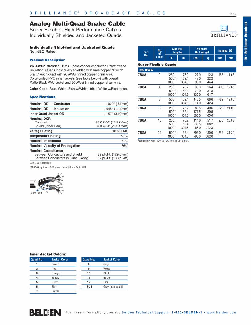
B R I L L I A N C E ® B R O A D C A S T C A B L E S 19.17
Analog Multi-Quad Snake Cable Super-Flexible, High-Performance CablesIndividually Shielded and Jacketed Quads
19•
Brill
ianc
e®Br
oadc
ast
F o r m o r e i n f o r m a t i o n , c o n t a c t B e l d e n Te c h n i c a l S u p p o r t : 1 - 8 0 0 - B E L D E N - 1 • w w w . b e l d e n . c o m
Individually Shielded and Jacketed QuadsNot NEC Rated
Product Description
26 AWG* stranded (19x38) bare copper conductor. Polyethyleneinsulation. Quads individually shielded with bare copper “FrenchBraid,” each quad with 26 AWG tinned copper drain wire. Color-coded PVC inner jackets (see table below) with overall Matte Black PVC jacket and 20 AWG tinned copper drain wire.
Color Code: Blue, White, Blue w/White stripe, White w/Blue stripe.
Specifications
Nominal OD — Conductor .020″ (.51mm)
Nominal OD — Insulation .045″ (1.14mm)
Inner Quad Jacket OD .157″ (3.99mm)
Nominal DCRConductor 36.0 Ω/M′ (11.8 Ω/km)Shield (Inner Pair) 6.8 Ω/M′ (2.23 Ω/km)
Voltage Rating 100V RMS
Temperature Rating 60°C
Nominal Impedance 40Ω
Nominal Velocity of Propagation 66%
Nominal CapacitanceBetween Conductors and Shield 39 pF/Ft. (129 pF/m)Between Conductors in Quad Config. 57 pF/Ft. (188 pF/m)
DCR = DC Resistance
*22 AWG equivalent DCR when connected to a 3-pin XLR
No.of
Quads mFt.
StandardLengths
kg
Standard Unit Weight Nominal OD
Inch mmLbs.
PartNo.
Super-Flexible Quads
26 AWG7884A 2 250 76.2 27.0 12.3 .458 11.63
500 † 152.4 49.0 22.21000 † 304.8 98.0 44.4
7885A 4 250 76.2 36.3 16.4 .498 12.65500 † 152.4 70.0 31.8
1000 † 304.8 136.0 61.77886A 8 500 † 152.4 146.5 66.6 .782 19.86
1000 † 304.8 314.0 142.47887A 12 250 76.2 89.5 40.6 .828 21.03
500 † 152.4 177.5 80.51000 † 304.8 365.0 165.6
7888A 16 250 76.2 114.0 51.7 .938 23.83500 † 152.4 238.5 108.2
1000 † 304.8 468.0 212.37889A 24 500 † 152.4 396.0 180.0 1.232 31.29
1000 † 304.8 798.0 362.0†Length may vary -10% to +0% from length shown.
French Braid
Inner Jacket Colors:
Quad No. Jacket Color1 Brown
2 Red
3 Orange
4 Yellow
5 Green
6 Blue
7 Purple
Quad No. Jacket Color8 Gray
9 White
10 Black
11 Beige
12 Pink
13-24 Gray (numbered)

B R I L L I A N C E ® B R O A D C A S T C A B L E S 19.18
Analog Multi-Pair Snake Cable CMR Rated CablesIndividually Shielded and Jacketed Twisted Pairs
F o r m o r e i n f o r m a t i o n , c o n t a c t B e l d e n Te c h n i c a l S u p p o r t : 1 - 8 0 0 - B E L D E N - 1 • w w w . b e l d e n . c o m
Individually Shielded and Jacketed PairsNEC: CMR (CEC: CMG FT4)
Product Description
24 AWG stranded (7x30) tinned copper conductor. Polyolefin insulation. Twisted pairs individual Beldfoil® shield (100% Coverage)and have numbered and color-coded PVC jackets (see Chart 7 inTechnical Information Section for colors). Pair jackets and shieldsare bonded so both strip simultaneously with automatic strippingequipment. Overall Beldfoil shield and 18 AWG tinned copper drainwire, plus overall Black PVC jacket and nylon rip cord.
Color Code: Red, Black.
Specifications
Nominal OD — Conductor .024″ (.61mm)
Nominal OD — Insulation .040″ (1.02mm)
Inner Pair Jacket OD .111″ (2.82mm)
ApprovalsNEC CMRCEC CMG FT4
Nominal DCRConductor 23.3Ω/M′ (76.4Ω/km)Shield (Inner Pair) 15.9Ω/M′ (52.1Ω/km)
Voltage Rating 300V RMS
Temperature Rating 75°C
Nominal Impedance 50Ω
Nominal Velocity of Propagation 66%
Nominal CapacitanceBetween Conductors 31 pF/Ft. (102 pF/m)Between Conductor/Shield* 58 pF/Ft. (191 pF/m)
DCR = DC Resistance
*Capacitance between one conductor and other conductors connected to shield.
No.of
Pairs mFt.
StandardLengths
kg
Standard Unit Weight Nominal OD
Inch mmLbs.
PartNo.
CMR Rated Twisted Pairs NEC: CMR (CEC: CMG FT4)
24 AWG1408R 4 500 152.4 36.0 16.3 .346 8.79
1000 304.8 73.0 33.21409R 6 500 152.4 50.5 22.9 .412 10.46
1000 304.8 100.0 45.41410R 8 500 152.4 62.0 28.1 .446 11.33
1000 304.8 122.0 55.31411R 12 500 152.4 91.0 41.3 .555 14.10
1000 304.8 175.0 79.41412R 16 500 152.4 117.0 53.1 .622 15.80
1000 304.8 232.0 105.21413R 20 500 152.4 145.0 65.8 .704 17.88
1000 304.8 293.0 132.91414R 24 500 152.4 182.0 82.6 .801 20.35
1000 304.8 374.0 169.61415R 26 500 152.4 193.5 87.8 .816 20.73
1000 304.8 397.0 180.11416R 32 500 152.4 228.5 103.7 .890 22.61
1000 304.8 465.0 210.9

B R I L L I A N C E ® B R O A D C A S T C A B L E S 19.19
19•
Brill
ianc
e®Br
oadc
ast
F o r m o r e i n f o r m a t i o n , c o n t a c t B e l d e n Te c h n i c a l S u p p o r t : 1 - 8 0 0 - B E L D E N - 1 • w w w . b e l d e n . c o m
Analog Multi-Pair Snake Cable Flexible, CM Rated CablesIndividually Shielded and Jacketed Twisted Pairs
Individually Shielded and Jacketed PairsNEC: CM (CEC: CM)
Product Description
24 AWG stranded (7x32) tinned copper conductor. Polyolefin insulation. Twisted pairs individual Beldfoil® shield (100% coverage)and have numbered and color-coded PVC jackets (see Chart 7 inTechnical Information Section for colors). Jackets and shields arebonded so both strip simultaneously. Overall Beldfoil shield and 24 AWG tinned copper drain wire, plus overall Matte Black PVCjacket and nylon rip cord.
Color Code: Red, Black.
Specifications
Nominal OD — Conductor .024″ (.61mm)
Nominal OD — Insulation .040″ (1.02mm)
Inner Pair Jacket OD .111″ (2.82mm)
ApprovalsNEC CMCEC CM
Nominal DCRConductor 23.3Ω/M′ (76.4Ω/km)Shield (Inner Pair) 15.9Ω/M′ (52.2Ω/km)
Voltage Rating 300V RMS
Temperature Rating 75°C
Nominal Impedance 50Ω
Nominal Velocity of Propagation 66%
Nominal CapacitanceBetween Conductors 31 pF/Ft. (102 pF/m)Between Conductor/Shield* 58 pF/Ft. (191 pF/m)
DCR = DC Resistance
*Capacitance between one conductor and other conductors connected to shield.
No.of
Pairs mFt.
StandardLengths
kg
Standard Unit Weight Nominal OD
Inch mmLbs.
PartNo.
Flexible, CM Rated Twisted Pairs NEC: CM (CEC: CM)
24 AWG1509C 2 500 152.4 24.0 10.9 .301 7.65
1000 304.8 46.0 20.91510C 4 500 152.4 35.5 16.1 .352 8.94
1000 304.8 72.0 32.61511C 6 500 152.4 52.0 23.6 .418 10.61
1000 304.8 102.0 46.31512C 8 500 152.4 65.5 29.7 .452 11.48
1000 304.8 124.0 56.31513C 12 500 152.4 89.5 40.6 .561 14.25(DT-12) 1000 304.8 178.0 80.71514C 16 500 152.4 122.5 55.6 .628 15.95
1000 304.8 241.0 109.31515C 20 500 152.4 142.5 64.6 .710 19.56
1000 304.8 288.0 130.61516C 24 500 152.4 180.5 81.9 .807 20.50
1000 304.8 371.0 168.31517C 26 500 152.4 187.5 85.1 .823 20.90
1000 304.8 385.0 174.61518C 32 500 152.4 236.5 107.3 .897 22.78
1000 304.8 481.0 218.21519C 52 500 152.4 372.5 169.0 1.117 28.37
1000 304.8 731.0 331.6
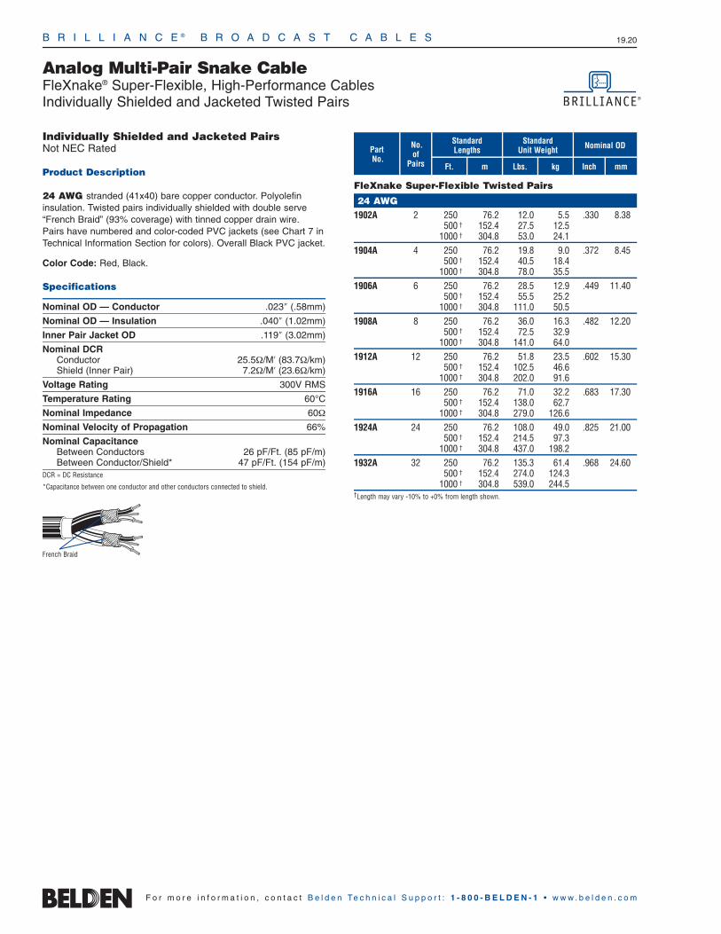
B R I L L I A N C E ® B R O A D C A S T C A B L E S 19.20
F o r m o r e i n f o r m a t i o n , c o n t a c t B e l d e n Te c h n i c a l S u p p o r t : 1 - 8 0 0 - B E L D E N - 1 • w w w . b e l d e n . c o m
Analog Multi-Pair Snake Cable FleXnake® Super-Flexible, High-Performance CablesIndividually Shielded and Jacketed Twisted Pairs
Individually Shielded and Jacketed PairsNot NEC Rated
Product Description
24 AWG stranded (41x40) bare copper conductor. Polyolefin insulation. Twisted pairs individually shielded with double serve“French Braid” (93% coverage) with tinned copper drain wire. Pairs have numbered and color-coded PVC jackets (see Chart 7 inTechnical Information Section for colors). Overall Black PVC jacket.
Color Code: Red, Black.
Specifications
Nominal OD — Conductor .023″ (.58mm)
Nominal OD — Insulation .040″ (1.02mm)
Inner Pair Jacket OD .119″ (3.02mm)
Nominal DCRConductor 25.5Ω/M′ (83.7Ω/km)Shield (Inner Pair) 7.2Ω/M′ (23.6Ω/km)
Voltage Rating 300V RMS
Temperature Rating 60°C
Nominal Impedance 60Ω
Nominal Velocity of Propagation 66%
Nominal CapacitanceBetween Conductors 26 pF/Ft. (85 pF/m)Between Conductor/Shield* 47 pF/Ft. (154 pF/m)
DCR = DC Resistance
*Capacitance between one conductor and other conductors connected to shield.
No.of
Pairs mFt.
StandardLengths
kg
Standard Unit Weight Nominal OD
Inch mmLbs.
PartNo.
FleXnake Super-Flexible Twisted Pairs
24 AWG1902A 2 250 76.2 12.0 5.5 .330 8.38
500 † 152.4 27.5 12.51000 † 304.8 53.0 24.1
1904A 4 250 76.2 19.8 9.0 .372 8.45500 † 152.4 40.5 18.4
1000 † 304.8 78.0 35.51906A 6 250 76.2 28.5 12.9 .449 11.40
500 † 152.4 55.5 25.21000 † 304.8 111.0 50.5
1908A 8 250 76.2 36.0 16.3 .482 12.20500 † 152.4 72.5 32.9
1000 † 304.8 141.0 64.01912A 12 250 76.2 51.8 23.5 .602 15.30
500 † 152.4 102.5 46.61000 † 304.8 202.0 91.6
1916A 16 250 76.2 71.0 32.2 .683 17.30500 † 152.4 138.0 62.7
1000 † 304.8 279.0 126.61924A 24 250 76.2 108.0 49.0 .825 21.00
500 † 152.4 214.5 97.31000 † 304.8 437.0 198.2
1932A 32 250 76.2 135.3 61.4 .968 24.60500 † 152.4 274.0 124.3
1000 † 304.8 539.0 244.5†Length may vary -10% to +0% from length shown.
French Braid
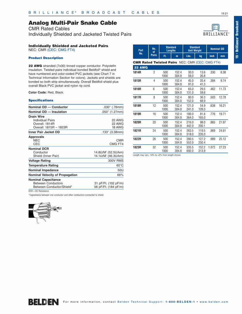
B R I L L I A N C E ® B R O A D C A S T C A B L E S 19.21
19•
Brill
ianc
e®Br
oadc
ast
F o r m o r e i n f o r m a t i o n , c o n t a c t B e l d e n Te c h n i c a l S u p p o r t : 1 - 8 0 0 - B E L D E N - 1 • w w w . b e l d e n . c o m
Analog Multi-Pair Snake Cable CMR Rated CablesIndividually Shielded and Jacketed Twisted Pairs
Individually Shielded and Jacketed PairsNEC: CMR (CEC: CMG FT4)
Product Description
22 AWG stranded (7x30) tinned copper conductor. Polyolefin insulation. Twisted pairs individual bonded Beldfoil® shield andhave numbered and color-coded PVC jackets (see Chart 7 inTechnical Information Section for colors). Jackets and shields arebonded so both strip simultaneously. Overall Beldfoil shield plusoverall Black PVC jacket and nylon rip cord.
Color Code: Red, Black.
Specifications
Nominal OD — Conductor .030″ (.76mm)
Nominal OD — Insulation .050″ (1.27mm)
Drain WireIndividual Pairs 22 AWGOverall: 1814R 22 AWGOverall: 1815R – 1823R 18 AWG
Inner Pair Jacket OD .133″ (3.38mm)
ApprovalsNEC CMRCEC CMG FT4
Nominal DCRConductor 14.8Ω/M′ (52.5Ω/km)Shield (Inner Pair) 14.1Ω/M′ (46.3Ω/km)
Voltage Rating 300V RMS
Temperature Rating 60°C
Nominal Impedance 50Ω
Nominal Velocity of Propagation 66%
Nominal CapacitanceBetween Conductors 31 pF/Ft. (102 pF/m)Between Conductor/Shield* 56 pF/Ft. (184 pF/m)
DCR = DC Resistance
*Capacitance between one conductor and other conductors connected to shield.
No.of
Pairs mFt.
StandardLengths
kg
Standard Unit Weight Nominal OD
Inch mmLbs.
PartNo.
CMR Rated Twisted Pairs NEC: CMR (CEC: CMG FT4)
22 AWG1814R 2 500 152.4 30.0 13.6 .330 8.38
1000 304.8 59.0 26.81815R 4 500 152.4 45.0 20.4 .384 9.74
1000 304.8 91.0 41.31816R 6 500 152.4 65.0 29.5 .462 11.73
1000 304.8 131.0 59.61817R 8 500 152.4 80.0 36.3 .503 12.78
1000 304.8 152.0 68.91818R 12 500 152.4 121.0 54.9 .638 16.21
1000 304.8 241.0 109.31819R 16 500 152.4 180.0 81.6 .776 19.71
1000 304.8 364.0 165.01820R 20 500 152.4 216.0 98.0 .865 21.97
1000 304.8 442.0 200.11821R 24 500 152.4 263.5 119.5 .969 24.61
1000 304.8 518.0 235.01822R 26 500 152.4 280.5 127.2 .989 25.12
1000 304.8 552.0 250.41823R 32 500 152.4 335.5 152.2 1.072 27.23
1000 304.8 692.0 313.9Length may vary -10% to +0% from length shown.

B R I L L I A N C E ® B R O A D C A S T C A B L E S 19.22
Analog Multi-Pair Snake Cable Flexible, Low-Capacitance CablesIndividually Shielded and Jacketed Twisted Pairs
F o r m o r e i n f o r m a t i o n , c o n t a c t B e l d e n Te c h n i c a l S u p p o r t : 1 - 8 0 0 - B E L D E N - 1 • w w w . b e l d e n . c o m
Individually Shielded and Jacketed PairsNot NEC Rated
Product Description
22 AWG stranded (7x30) tinned copper conductor. Datalene®
insulation. Twisted pairs individual Beldfoil® shield (100% Coverage)and have numbered and color-coded PVC jackets (see Chart 7 inTechnical Information Section for colors). Pair jackets and shieldsare bonded so both strip simultaneously with automatic strippingequipment. Overall Matte Black PVC jacket and nylon rip cord.
Datalene insulation features include a low dielectric constant and alow dissipation factor for high-speed, low-distortion data handling.Physical properties include good crush resistance and light weight.
Color Code: Red, Black.
Specifications
Nominal OD — Conductor .030″ (.76mm)
Nominal OD — Insulation .060″ (1.52mm)
Inner Pair Jacket OD .153″ (3.89mm)
Nominal DCRConductor 15.0Ω/M′ (52.5Ω/km)Shield (Inner Pair) 10.6Ω/M′ (34.8Ω/km)
Voltage Rating 150V RMS
Temperature Rating 60°C
Nominal Impedance 70Ω
Nominal Velocity of Propagation 78%
Nominal CapacitanceBetween Conductors 19 pF/Ft. (62 pF/m)Between Conductor/Shield* 35 pF/Ft. (115 pF/m)
DCR = DC Resistance
*Capacitance between one conductor and other conductors connected to shield.
No.of
Pairs mFt.
StandardLengths
kg
Standard Unit Weight Nominal OD
Inch mmLbs.
PartNo.
Flexible, Low-Capacitance Twisted Pairs
22 AWG1217B 4 500 152.4 53.0 24.0 .458 11.63
1000 304.8 107.0 48.51218B 6 500 152.4 79.5 36.1 .578 14.68
1000 304.8 152.0 68.91219B 9 500 152.4 115.5 52.4 .700 17.78
1000 304.8 234.0 106.11220B 12 500 152.4 141.0 70.0 .760 19.30
1000 304.8 286.0 129.71222B 16 500 152.4 188.0 85.3 .852 21.64
1000 304.8 384.0 174.21225B 20 500 152.4 240.0 108.8 .960 24.38
1000 304.8 471.0 213.61427B 24 1000 304.8 588.0 266.7 1.088 27.641221B 28 500 152.4 335.0 152.0 1.140 28.96
1000 304.8 676.0 306.61226B 32 500 152.4 369.0 167.4 1.183 30.05
1000 304.8 744.0 337.51428B† 52 1000 304.8 1141.0 517.5 1.496 38.00†1428B available by special order. Please contact Belden for lead time.
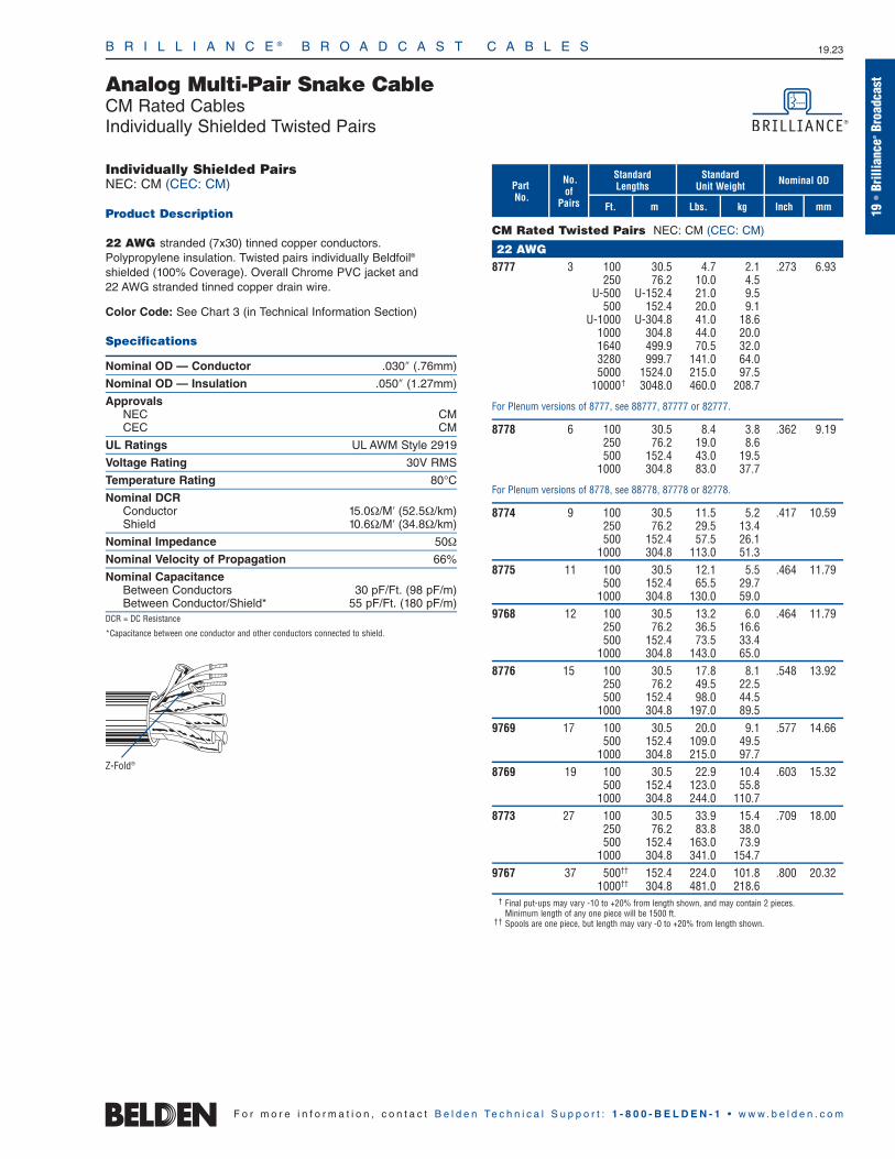
B R I L L I A N C E ® B R O A D C A S T C A B L E S 19.23
Analog Multi-Pair Snake Cable CM Rated CablesIndividually Shielded Twisted Pairs
19•
Brill
ianc
e®Br
oadc
ast
F o r m o r e i n f o r m a t i o n , c o n t a c t B e l d e n Te c h n i c a l S u p p o r t : 1 - 8 0 0 - B E L D E N - 1 • w w w . b e l d e n . c o m
Individually Shielded PairsNEC: CM (CEC: CM)
Product Description
22 AWG stranded (7x30) tinned copper conductors.Polypropylene insulation. Twisted pairs individually Beldfoil®
shielded (100% Coverage). Overall Chrome PVC jacket and 22 AWG stranded tinned copper drain wire.
Color Code: See Chart 3 (in Technical Information Section)
Specifications
Nominal OD — Conductor .030″ (.76mm)
Nominal OD — Insulation .050″ (1.27mm)
ApprovalsNEC CMCEC CM
UL Ratings UL AWM Style 2919
Voltage Rating 30V RMS
Temperature Rating 80°C
Nominal DCRConductor 15.0Ω/M′ (52.5Ω/km)Shield 10.6Ω/M′ (34.8Ω/km)
Nominal Impedance 50Ω
Nominal Velocity of Propagation 66%
Nominal CapacitanceBetween Conductors 30 pF/Ft. (98 pF/m)Between Conductor/Shield* 55 pF/Ft. (180 pF/m)
DCR = DC Resistance
*Capacitance between one conductor and other conductors connected to shield.
Z-Fold®
No.of
Pairs mFt.
StandardLengths
kg
Standard Unit Weight Nominal OD
Inch mmLbs.
PartNo.
CM Rated Twisted Pairs NEC: CM (CEC: CM)
22 AWG8777 3 100 30.5 4.7 2.1 .273 6.93
250 76.2 10.0 4.5U-500 U-152.4 21.0 9.5
500 152.4 20.0 9.1U-1000 U-304.8 41.0 18.6
1000 304.8 44.0 20.01640 499.9 70.5 32.03280 999.7 141.0 64.05000 1524.0 215.0 97.5
10000† 3048.0 460.0 208.7
For Plenum versions of 8777, see 88777, 87777 or 82777.
8778 6 100 30.5 8.4 3.8 .362 9.19250 76.2 19.0 8.6500 152.4 43.0 19.5
1000 304.8 83.0 37.7
For Plenum versions of 8778, see 88778, 87778 or 82778.
8774 9 100 30.5 11.5 5.2 .417 10.59250 76.2 29.5 13.4500 152.4 57.5 26.1
1000 304.8 113.0 51.38775 11 100 30.5 12.1 5.5 .464 11.79
500 152.4 65.5 29.71000 304.8 130.0 59.0
9768 12 100 30.5 13.2 6.0 .464 11.79250 76.2 36.5 16.6500 152.4 73.5 33.4
1000 304.8 143.0 65.08776 15 100 30.5 17.8 8.1 .548 13.92
250 76.2 49.5 22.5500 152.4 98.0 44.5
1000 304.8 197.0 89.59769 17 100 30.5 20.0 9.1 .577 14.66
500 152.4 109.0 49.51000 304.8 215.0 97.7
8769 19 100 30.5 22.9 10.4 .603 15.32500 152.4 123.0 55.8
1000 304.8 244.0 110.78773 27 100 30.5 33.9 15.4 .709 18.00
250 76.2 83.8 38.0500 152.4 163.0 73.9
1000 304.8 341.0 154.79767 37 500†† 152.4 224.0 101.8 .800 20.32
1000†† 304.8 481.0 218.6† Final put-ups may vary -10 to +20% from length shown, and may contain 2 pieces.
Minimum length of any one piece will be 1500 ft.†† Spools are one piece, but length may vary -0 to +20% from length shown.
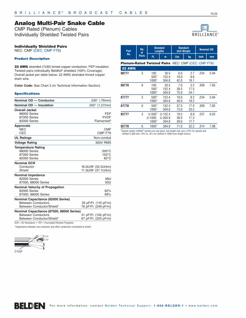
B R I L L I A N C E ® B R O A D C A S T C A B L E S 19.24
F o r m o r e i n f o r m a t i o n , c o n t a c t B e l d e n Te c h n i c a l S u p p o r t : 1 - 8 0 0 - B E L D E N - 1 • w w w . b e l d e n . c o m
Analog Multi-Pair Snake Cable CMP Rated (Plenum) CablesIndividually Shielded Twisted Pairs
Individually Shielded PairsNEC: CMP (CEC: CMP FT6)
Product Description
22 AWG stranded (7x30) tinned copper conductors. FEP insulation.Twisted pairs individually Beldfoil® shielded (100% Coverage).Overall jacket per table below. 22 AWG stranded tinned copperdrain wire.
Color Code: See Chart 3 (in Technical Information Section)
Specifications
Nominal OD — Conductor .030″ (.76mm)
Nominal OD — Insulation .050″ (1.27mm)
Overall Jacket88000 Series FEP87000 Series PVDF82000 Series Flamarrest®
ApprovalsNEC CMPCEC CMP FT6
UL Ratings Non-conduit
Voltage Rating 300V RMS
Temperature Rating88000 Series 200°C87000 Series 150°C82000 Series 60°C
Nominal DCRConductor 16.0Ω/M′ (52.5Ω/km)Shield 11.3Ω/M′ (37.1Ω/km)
Nominal Impedance82000 Series 46Ω87000, 88000 Series 50Ω
Nominal Velocity of Propagation82000 Series 62%87000, 88000 Series 69%
Nominal Capacitance (82000 Series)Between Conductors 35 pF/Ft. (115 pF/m)Between Conductor/Shield* 76 pF/Ft. (249 pF/m)
Nominal Capacitance (87000, 88000 Series)Between Conductors 31 pF/Ft. (102 pF/m)Between Conductor/Shield* 67 pF/Ft. (220 pF/m)
DCR = DC Resistance • FEP = Fluorinated Ethylene Propylene
*Capacitance between one conductor and other conductors connected to shield.
No.of
Pairs mFt.
StandardLengths
kg
Standard Unit Weight Nominal OD
Inch mmLbs.
PartNo.
Plenum-Rated Twisted Pairs NEC: CMP (CEC: CMP FT6)
22 AWG88777 3 100 30.5 6.0 2.7 .234 5.94
500† 152.4 19.0 8.61000† 304.8 42.0 19.1
88778 6 100 30.5 7.0 3.2 .309 7.85500† 152.4 38.5 17.5
1000† 304.8 75.0 34.187777 3 500† 152.4 18.0 8.2 .234 5.94
1000† 304.8 40.0 18.287778 6 500† 152.4 37.5 17.0 .309 7.85
1000† 304.8 73.0 33.282777 3 U-500† U-152.4 19.5 8.9 .237 6.02
U-1000 U-304.8 38.0 17.31000† 304.8 39.0 17.7
82778 6 1000† 304.8 71.0 32.2 .314 7.98†Spools and/or UnReel® cartons are one piece, but length may vary ±10% for spools and
UnReel U-500 and -10% to +5% for UnReel U-1000 from length shown.
Z-Fold®
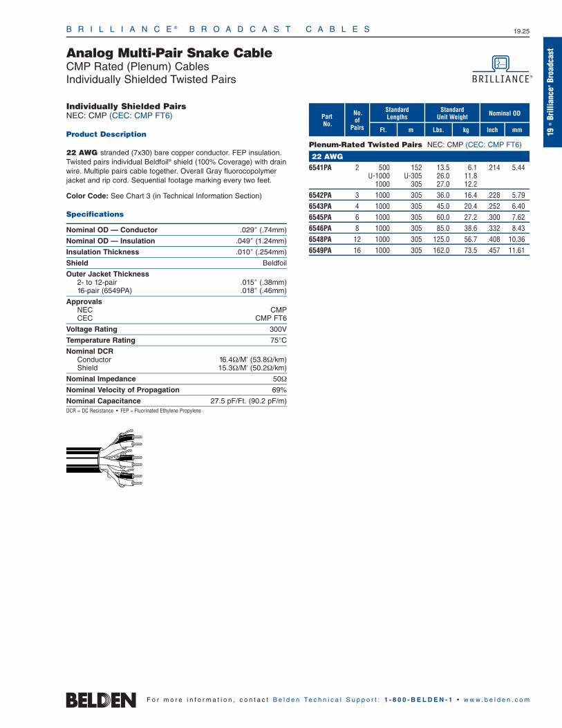
B R I L L I A N C E ® B R O A D C A S T C A B L E S 19.25
Analog Multi-Pair Snake Cable CMP Rated (Plenum) CablesIndividually Shielded Twisted Pairs
19•
Brill
ianc
e®Br
oadc
ast
F o r m o r e i n f o r m a t i o n , c o n t a c t B e l d e n Te c h n i c a l S u p p o r t : 1 - 8 0 0 - B E L D E N - 1 • w w w . b e l d e n . c o m
Individually Shielded PairsNEC: CMP (CEC: CMP FT6)
Product Description
22 AWG stranded (7x30) bare copper conductor. FEP insulation.Twisted pairs individual Beldfoil® shield (100% Coverage) with drainwire. Multiple pairs cable together. Overall Gray fluorocopolymerjacket and rip cord. Sequential footage marking every two feet.
Color Code: See Chart 3 (in Technical Information Section)
Specifications
Nominal OD — Conductor .029″ (.74mm)
Nominal OD — Insulation .049″ (1.24mm)
Insulation Thickness .010″ (.254mm)
Shield Beldfoil
Outer Jacket Thickness2- to 12-pair .015″ (.38mm)16-pair (6549PA) .018″ (.46mm)
ApprovalsNEC CMPCEC CMP FT6
Voltage Rating 300V
Temperature Rating 75°C
Nominal DCRConductor 16.4Ω/M′ (53.8Ω/km)Shield 15.3Ω/M′ (50.2Ω/km)
Nominal Impedance 50Ω
Nominal Velocity of Propagation 69%
Nominal Capacitance 27.5 pF/Ft. (90.2 pF/m)DCR = DC Resistance • FEP = Fluorinated Ethylene Propylene
No.of
Pairs mFt.
StandardLengths
kg
Standard Unit Weight Nominal OD
Inch mmLbs.
PartNo.
Plenum-Rated Twisted Pairs NEC: CMP (CEC: CMP FT6)
22 AWG6541PA 2 500 152 13.5 6.1 .214 5.44
U-1000 U-305 26.0 11.81000 305 27.0 12.2
6542PA 3 1000 305 36.0 16.4 .228 5.796543PA 4 1000 305 45.0 20.4 .252 6.406545PA 6 1000 305 60.0 27.2 .300 7.626546PA 8 1000 305 85.0 38.6 .332 8.436548PA 12 1000 305 125.0 56.7 .408 10.366549PA 16 1000 305 162.0 73.5 .457 11.61
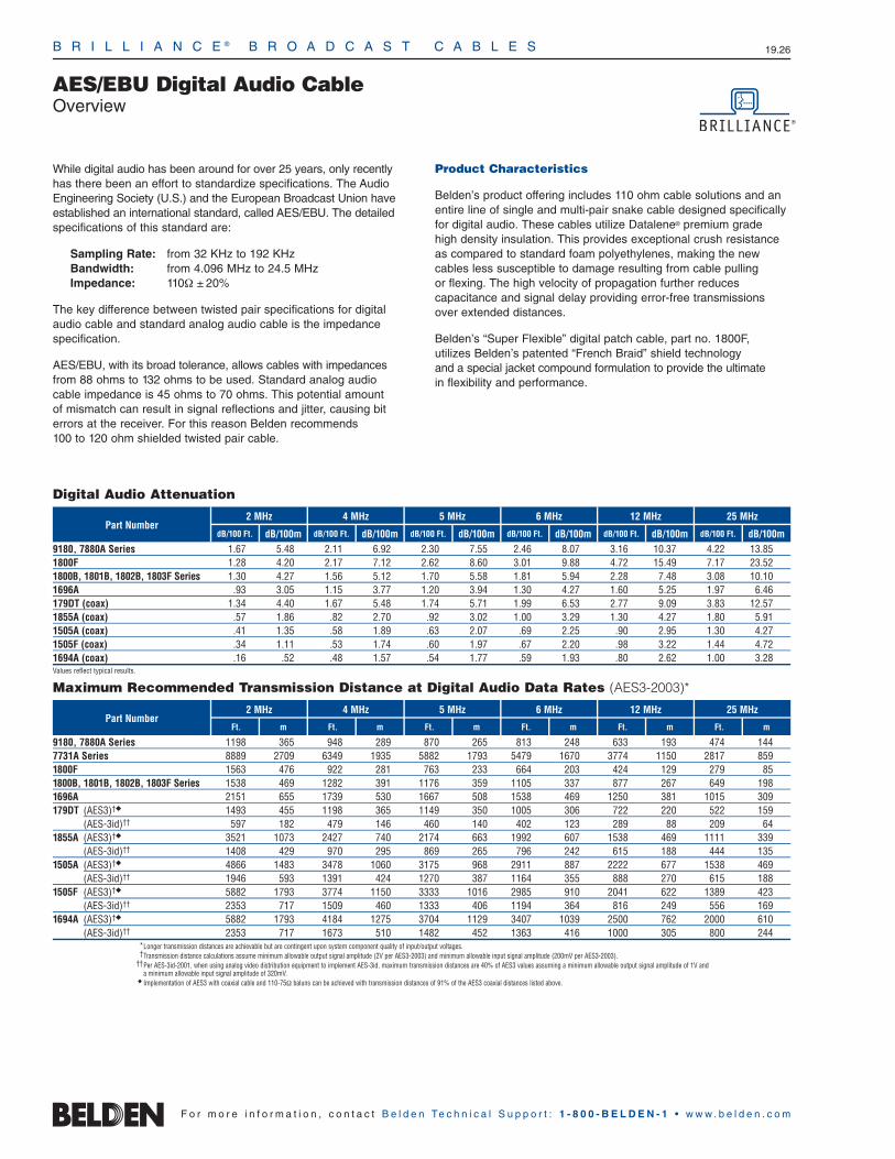
B R I L L I A N C E ® B R O A D C A S T C A B L E S 19.26
AES/EBU Digital Audio CableOverview
F o r m o r e i n f o r m a t i o n , c o n t a c t B e l d e n Te c h n i c a l S u p p o r t : 1 - 8 0 0 - B E L D E N - 1 • w w w . b e l d e n . c o m
While digital audio has been around for over 25 years, only recentlyhas there been an effort to standardize specifications. The AudioEngineering Society (U.S.) and the European Broadcast Union haveestablished an international standard, called AES/EBU. The detailedspecifications of this standard are:
Sampling Rate: from 32 KHz to 192 KHzBandwidth: from 4.096 MHz to 24.5 MHzImpedance: 110Ω ± 20%
The key difference between twisted pair specifications for digitalaudio cable and standard analog audio cable is the impedancespecification.
AES/EBU, with its broad tolerance, allows cables with impedancesfrom 88 ohms to 132 ohms to be used. Standard analog audio cable impedance is 45 ohms to 70 ohms. This potential amount of mismatch can result in signal reflections and jitter, causing biterrors at the receiver. For this reason Belden recommends 100 to 120 ohm shielded twisted pair cable.
Product Characteristics
Belden’s product offering includes 110 ohm cable solutions and anentire line of single and multi-pair snake cable designed specificallyfor digital audio. These cables utilize Datalene® premium grade high density insulation. This provides exceptional crush resistanceas compared to standard foam polyethylenes, making the newcables less susceptible to damage resulting from cable pulling or flexing. The high velocity of propagation further reduces capacitance and signal delay providing error-free transmissionsover extended distances.
Belden’s “Super Flexible” digital patch cable, part no. 1800F, utilizes Belden’s patented “French Braid” shield technology and a special jacket compound formulation to provide the ultimate in flexibility and performance.
2 MHz 4 MHz 5 MHz 6 MHz 12 MHz 25 MHzPart Number
Ft. m Ft. m Ft. m Ft. m Ft. m Ft. m
Maximum Recommended Transmission Distance at Digital Audio Data Rates (AES3-2003)*
Digital Audio Attenuation
dB/100 Ft. dB/100m
2 MHz 4 MHz 5 MHz 6 MHz 12 MHz 25 MHzPart Number
9180, 7880A Series 1.67 5.48 2.11 6.92 2.30 7.55 2.46 8.07 3.16 10.37 4.22 13.851800F 1.28 4.20 2.17 7.12 2.62 8.60 3.01 9.88 4.72 15.49 7.17 23.521800B, 1801B, 1802B, 1803F Series 1.30 4.27 1.56 5.12 1.70 5.58 1.81 5.94 2.28 7.48 3.08 10.101696A .93 3.05 1.15 3.77 1.20 3.94 1.30 4.27 1.60 5.25 1.97 6.46179DT (coax) 1.34 4.40 1.67 5.48 1.74 5.71 1.99 6.53 2.77 9.09 3.83 12.571855A (coax) .57 1.86 .82 2.70 .92 3.02 1.00 3.29 1.30 4.27 1.80 5.911505A (coax) .41 1.35 .58 1.89 .63 2.07 .69 2.25 .90 2.95 1.30 4.271505F (coax) .34 1.11 .53 1.74 .60 1.97 .67 2.20 .98 3.22 1.44 4.721694A (coax) .16 .52 .48 1.57 .54 1.77 .59 1.93 .80 2.62 1.00 3.28Values reflect typical results.
9180, 7880A Series 1198 365 948 289 870 265 813 248 633 193 474 1447731A Series 8889 2709 6349 1935 5882 1793 5479 1670 3774 1150 2817 8591800F 1563 476 922 281 763 233 664 203 424 129 279 851800B, 1801B, 1802B, 1803F Series 1538 469 1282 391 1176 359 1105 337 877 267 649 1981696A 2151 655 1739 530 1667 508 1538 469 1250 381 1015 309179DT (AES3)† 1493 455 1198 365 1149 350 1005 306 722 220 522 159
(AES-3id)†† 597 182 479 146 460 140 402 123 289 88 209 641855A (AES3)† 3521 1073 2427 740 2174 663 1992 607 1538 469 1111 339
(AES-3id)†† 1408 429 970 295 869 265 796 242 615 188 444 1351505A (AES3)† 4866 1483 3478 1060 3175 968 2911 887 2222 677 1538 469
(AES-3id)†† 1946 593 1391 424 1270 387 1164 355 888 270 615 1881505F (AES3)† 5882 1793 3774 1150 3333 1016 2985 910 2041 622 1389 423
(AES-3id)†† 2353 717 1509 460 1333 406 1194 364 816 249 556 1691694A (AES3)† 5882 1793 4184 1275 3704 1129 3407 1039 2500 762 2000 610
(AES-3id)†† 2353 717 1673 510 1482 452 1363 416 1000 305 800 244*Longer transmission distances are achievable but are contingent upon system component quality of input/output voltages.†Transmission distance calculations assume minimum allowable output signal amplitude (2V per AES3-2003) and minimum allowable input signal amplitude (200mV per AES3-2003).
††Per AES-3id-2001, when using analog video distribution equipment to implement AES-3id, maximum transmission distances are 40% of AES3 values assuming a minimum allowable output signal amplitude of 1V and a minimum allowable input signal amplitude of 320mV.
Implementation of AES3 with coaxial cable and 110-75Ω baluns can be achieved with transmission distances of 91% of the AES3 coaxial distances listed above.
dB/100 Ft. dB/100m dB/100 Ft. dB/100m dB/100 Ft. dB/100m dB/100 Ft. dB/100m dB/100 Ft. dB/100m

B R I L L I A N C E ® B R O A D C A S T C A B L E S 19.27
AES/EBU Digital Audio CableSingle- and Double-Pair Cables
19•
Brill
ianc
e®Br
oadc
ast
F o r m o r e i n f o r m a t i o n , c o n t a c t B e l d e n Te c h n i c a l S u p p o r t : 1 - 8 0 0 - B E L D E N - 1 • w w w . b e l d e n . c o m
110 Ohm • 26 AWG Stranded (7x34) .018″ TC Conductors • Twisted Pair • Beldfoil® Shield (100% Coverage) • 26 AWG Stranded TC Drain Wire
Datalene® Insulation • Chrome or Purple PVC Jacket2-Conductor Digital 9180 NEC: 1 Black, 1000 304.8 10.0 4.5 37.3Ω/M′ 23.1Ω/M′ .144 3.66 110 76% 13 43 26 85Video Time Code Cable CMR White 122.3Ω/km 75.8Ω/km75°C CEC:
CMG FT4
24 AWG Stranded (7x32) Tinned Copper Conductors • Twisted Pairs • Overall Beldfoil Shield (100% Coverage) • 24 AWG Drain Wire
Datalene Insulation • Gray or Purple PVC Jacket60°C 1800B NEC: 1 Black, 500 152.4 8.0 3.6 23.7Ω/M′ 18.9Ω/M′ .177 4.57 110 76% 12 39 26 85
CMG Red U-1000 U-304.8 17.0 7.7 77.7Ω/km 62.0Ω/kmCEC: 1000 304.8 16.0 7.3
CMG FT4 5000 1524.0 90.0 40.8
500 ft. put-up available in Gray only. 5000 ft. put-up available in Purple only.The jacket and shield are bonded so both can be removed with automatic stripping equipment.
24 AWG Stranded (42x40) HC BC Conductors • Conductors Cabled with Fillers • TC “French Braid” Shield (95% Coverage) • BC Drain Wire
Datalene Insulation • Matte PVC Jacket (Available in Red, Yellow, Green, Blue, Gray or Black)Digital Mic Cable 1800F NEC: 1 Black, 500 152.4 12.0 5.5 23.7Ω/M′ 5.0Ω/M′ .211 5.36 110 76% 12 39 26 85High-Flex CL2R Red U-1000 U-304.8 26.0 11.8 77.7Ω/km 16.4Ω/km60°C 1000 304.8 24.0 10.9
500 ft. and 1000 ft. put-ups available in Black only.
24 AWG Stranded (7x32) TC Conductors • Twisted Pairs • Overall Beldfoil Shield (100% Coverage) • 24 AWG TC Drain Wire
Plenum • Foam FEP Teflon® Insulation • Flamarrest® Jacket (Available in Natural White or Purple) 75°C, Non-conduit 1801B NEC: 1 Black, 500 152.4 6.0 2.7 23.7Ω/M′ 18.9Ω/M′ .165 4.19 110 78% 12 39 26 85
CMP Red U-1000 U-304.8 14.0 6.4 77.7Ω/km 62.0Ω/kmCEC: 1000 304.8 12.0 5.5
CMP FT6
24 AWG Stranded (7x32) TC Conductors • Dual Twisted Pairs • Overall Beldfoil Shield (100% Coverage) • 24 AWG TC Drain Wire
Datalene Insulation • Purple PVC Jacket in Zip-Cord Construction60°C 1802B NEC: 2 Black, 500 152.4 16.5 7.5 23.7Ω/M′ 18.9Ω/M′ .180 4.57 110 76% 12 39 26 85
CMG Red U-1000 U-304.8 35.0 15.9 77.7Ω/km 62.0Ω/km x xCEC: 1000 304.8 37.0 16.8 .360 9.14
CMG FT4
The jacket and shield are bonded so both can be removed with automatic stripping equipment.
22 AWG Stranded (7x30) TC Conductors • Twisted Pair with Fillers • Overall Beldfoil + TC Braid Shield (90% Coverage) • 24 AWG Drain Wire
Datalene Insulation • Black High-Flex Matte PVC JacketDMX512 Type 1696A — 1 Blue, 250 76.2 8.0 3.6 17.8Ω/M′ 4.6Ω/M′ .234 5.94 110 76% 13 43 26 85High-Flex White 500 152.4 14.5 6.6 48.5Ω/km 15.2Ω/km60°C U-1000 U-304.8 30.0 13.6
1000 304.8 32.0 14.5
BC = Bare Copper • DCR = DC Resistance • FEP = Fluorinated Ethylene Propylene • HC = High-conductivity • TC = Tinned Copper
*Capacitance between conductors. **Capacitance between one conductor and other conductors connected to shield.
UL NEC/C(UL) CEC
Type
Part No.
No.of
Pairs Ft. m
Standard Lengths
StandardUnit Weight
Lbs. kg
Nom. DCR
Cond. ShieldDescription Color
Code
Nominal OD
Inch mm
Nom.Imp.(Ω)
Nom.Vel.of
Prop.
Nom. Capacitance
*pF/Ft.
*pF/m
**pF/Ft.
**pF/m
For cross-connect use with 1803F (et al.) Digital Audio Snake Cables, see page 19.28.
For Plenum version of 1800B, see 1801B.
For cross-connect use with 7891A (et al.) Digital Audio Snake Cables, see page 19.28.
Teflon is a DuPont trademark.
Shorting Fold
French Braid
Z-Fold®

B R I L L I A N C E ® B R O A D C A S T C A B L E S 19.28
AES/EBU Digital Audio CableMulti-Pair Snake CablesIndividually Shielded and Jacketed Pairs
F o r m o r e i n f o r m a t i o n , c o n t a c t B e l d e n Te c h n i c a l S u p p o r t : 1 - 8 0 0 - B E L D E N - 1 • w w w . b e l d e n . c o m
Individually Shielded and Jacketed PairsNEC: CMG (CEC: CMG FT4)
Product Description
26 AWG or 24 AWG stranded tinned copper conductor. Datalene®
insulation. Pairs individually shielded with bonded Beldfoil® with adrain wire and have numbered and color-coded PVC jackets (seeChart 7 in Technical Information Section for colors). Pair jacketsand shields are bonded so both strip simultaneously with automaticstripping equipment. Overall Beldfoil shield/drain wire plus overallPurple PVC jacket and nylon rip cord.
Datalene insulation features include low dielectric constant and a dissipation factor for high-speed, low-distortion data handling. Physical properties include good crush resistance and light weight.
Color Code: Black, Red.
Specifications
Nominal OD — Conductor26 AWG .019″ (.48mm)24 AWG .024″ (.60mm)
Nominal OD — Insulation26 AWG .054″ (1.37mm)24 AWG .070″ (1.78mm)
Inner Pair Jacket OD26 AWG .136″ (3.45mm)24 AWG .167″ (4.24mm)
ApprovalsNEC CMGCEC CMG FT4
Nominal DCR (26 AWG)Conductor 37.3Ω/M′ (122.3Ω/km)Shield 25.5Ω/M′ (83.6Ω/km)
Nominal DCR (24 AWG)Conductor 23.7Ω/M′ (77.7Ω/km)Shield 18.9Ω/M′ (62.0Ω/km)
Nominal Impedance 110Ω ±10Ω
Nominal Velocity of Propagation 76%
Nominal Capacitance (26 AWG)Between Conductors 12.5 pF/Ft. (41 pF/m)Between Conductor/Shield* 25 pF/Ft. (82 pF/m)
Nominal Capacitance (24 AWG)Between Conductors 12 pF/Ft. (39 pF/m)Between Conductor/Shield* 26 pF/Ft. (86 pF/m)
DCR = DC Resistance
*Capacitance between one conductor and other conductors connected to shield.
No.of
Pairs mFt.
StandardLengths
kg
Standard Unit Weight Nominal OD
Inch mmLbs.
PartNo.
Individually Shielded & Jacketed NEC: CMG (CEC: CMG FT4)
26 AWG (7x34)
7891A 2 500 152.4 28.0 12.7 .343 8.711000 304.8 56.0 25.5
7890A 4 100 30.5 8.2 3.7 .399 10.13250 76.2 18.0 8.2500 152.4 31.0 14.1
1000 304.8 61.0 27.77880A† 8 250 76.2 28.0 12.7 .541 13.74
500 152.4 57.0 25.91000 304.8 142.0 64.4
Fits metal shell 25-pin D-sub connectors.
7892A 12 500 152.4 85.5 37.9 .679 17.251000 304.8 174.0 79.1
7893A 16 500 152.4 109.5 49.8 .770 19.561000 304.8 240.0 109.1
Individually Shielded & Jacketed NEC: CMG (CEC: CMG FT4)
24 AWG (7x32) • Flexible1803F 4 500 152.4 57.5 26.1 .488 12.39
1000 304.8 107.0 48.61805F 8 500 152.4 106.5 48.3 .661 16.79
1000 304.8 211.0 95.71806F 12 500 152.4 160.0 72.6 .829 21.06
1000 304.8 330.0 149.71850F 16 500 152.4 208.0 94.4 .944 23.98
1000 304.8 407.0 184.61852F 24 500 152.4 321.0 145.6 1.205 30.61
1000 304.8 644.0 292.11854F 32 1000 304.8 841.0 381.5 1.346 34.19†7880A is designed to fit in 25-pin D-sub connectors used in digital console board equipment.
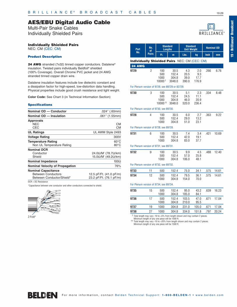
B R I L L I A N C E ® B R O A D C A S T C A B L E S 19.29
AES/EBU Digital Audio CableMulti-Pair Snake CablesIndividually Shielded Pairs
19•
Brill
ianc
e®Br
oadc
ast
F o r m o r e i n f o r m a t i o n , c o n t a c t B e l d e n Te c h n i c a l S u p p o r t : 1 - 8 0 0 - B E L D E N - 1 • w w w . b e l d e n . c o m
Individually Shielded PairsNEC: CM (CEC: CM)
Product Description
24 AWG stranded (7x32) tinned copper conductors. Datalene®
insulation. Twisted pairs individually Beldfoil® shielded (100% Coverage). Overall Chrome PVC jacket and 24 AWGstranded tinned copper drain wire.
Datalene insulation features include low dielectric constant and a dissipation factor for high-speed, low-distortion data handling. Physical properties include good crush resistance and light weight.
Color Code: See Chart 3 (in Technical Information Section)
Specifications
Nominal OD — Conductor .024″ (.60mm)
Nominal OD — Insulation .061″ (1.55mm)
ApprovalsNEC CMCEC CM
UL Ratings UL AWM Style 2493
Voltage Rating 300V
Temperature Rating 60°CNon UL Temperature Rating 80°C
Nominal DCRConductor 24.0Ω/M′ (78.7Ω/km)Shield 15.0Ω/M′ (49.2Ω/km)
Nominal Impedance 100Ω
Nominal Velocity of Propagation 76%
Nominal Capacitance Between Conductors 12.5 pF/Ft. (41.0 pF/m)Between Conductor/Shield* 23.2 pF/Ft. (76.1 pF/m)
DCR = DC Resistance
*Capacitance between one conductor and other conductors connected to shield.
Z-Fold®
No.of
Pairs mFt.
StandardLengths
kg
Standard Unit Weight Nominal OD
Inch mmLbs.
PartNo.
Individually Shielded Pairs NEC: CM (CEC: CM)
24 AWG9729 2 100 30.5 4.3 2.0 .266 6.76
500 152.4 20.5 9.31000 304.8 39.0 17.7
10000 † 3048.0 390.0 176.9
For Plenum version of 9729, see 89729 or 82729.
9730 3 100 30.5 5.1 2.3 .334 8.48500 152.4 24.5 11.1
1000 304.8 46.0 20.910000 †† 3048.0 520.0 236.4
For Plenum version of 9730, see 89730.
9728 4 100 30.5 6.0 2.7 .363 9.22500 152.4 29.0 13.2
1000 304.8 51.0 23.1
For Plenum version of 9728, see 89728.
9731 6 100 30.5 7.4 3.4 .421 10.69500 152.4 42.0 19.1
1000 304.8 83.0 37.7
For Plenum version of 9731, see 89731.
9732 9 100 30.5 9.9 4.5 .488 12.40500 152.4 57.0 25.8
1000 304.8 106.0 48.1
For Plenum version of 9732, see 89732.
9733 11 500 152.4 75.0 34.1 .575 14.619734 12 500 152.4 79.5 36.1 .575 14.61
1000 304.8 154.0 70.0
For Plenum version of 9734, see 89734.
9735 15 500 152.4 95.0 43.2 .639 16.231000 304.8 185.0 84.1
9736 17 500 152.4 103.5 47.0 .671 17.041000 304.8 210.0 95.5
9737 19 1000 304.8 231.0 105.0 .671 17.049738 27 1000 304.8 334.0 151.8 .797 20.24
† Total length may vary -10 to +5% from length shown and may contain 2 pieces.Minimum length of any one piece will be 1500 ft.
†† Total length may vary -10 to +20% from length shown and may contain 2 pieces.Minimum length of any one piece will be 1500 ft.
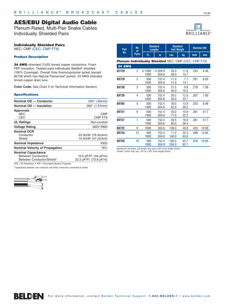
B R I L L I A N C E ® B R O A D C A S T C A B L E S 19.30
AES/EBU Digital Audio CablePlenum-Rated, Multi-Pair Snake CablesIndividually Shielded Pairs
F o r m o r e i n f o r m a t i o n , c o n t a c t B e l d e n Te c h n i c a l S u p p o r t : 1 - 8 0 0 - B E L D E N - 1 • w w w . b e l d e n . c o m
Individually Shielded PairsNEC: CMP (CEC: CMP FT6)
Product Description
24 AWG stranded (7x32) tinned copper conductors. Foam FEP insulation. Twisted pairs individually Beldfoil® shielded (100% Coverage). Overall Gray fluorocopolymer jacket (except82729 which has Natural Flamarrest® jacket). 24 AWG strandedtinned copper drain wire.
Color Code: See Chart 5 (in Technical Information Section)
Specifications
Nominal OD — Conductor .024″ (.60mm)
Nominal OD — Insulation .062″ (1.57mm)
ApprovalsNEC CMPCEC CMP FT6
UL Ratings Non-conduit
Voltage Rating 300V RMS
Nominal DCRConductor 23.3Ω/M′ (76.4Ω/km)Shield 14.4Ω/M′ (47.2Ω/km)
Nominal Impedance 100Ω
Nominal Velocity of Propagation 76%
Nominal Capacitance Between Conductors 13.5 pF/Ft. (44 pF/m)Between Conductor/Shield* 22.5 pF/Ft. (73.8 pF/m)
DCR = DC Resistance • FEP = Fluorinated Ethylene Propylene
*Capacitance between one conductor and other conductors connected to shield.
No.of
Pairs mFt.
StandardLengths
kg
Standard Unit Weight Nominal OD
Inch mmLbs.
PartNo.
Plenum Individually Shielded NEC: CMP (CEC: CMP FT6)
24 AWG82729 2 U-1000 U-304.8 26.0 11.8 .255 6.48
1000 304.8 28.0 12.789729 2 500 152.4 17.0 7.7 .261 6.63
1000 304.8 31.0 14.189730 3 500 152.4 21.5 9.8 .278 7.06
1000 304.8 40.0 18.289728 4 500 152.4 26.5 12.0 .307 7.80
1000 304.8 50.0 22.789705 5 500 152.4 30.5 13.9 .333 8.46
1000 304.8 62.0 28.289731 6 500 152.4 35.0 15.9 .361 9.17
1000 304.8 71.0 32.389757 7 500 152.4 39.5 18.0 .361 9.17
1000 304.8 80.0 36.489732 9 1000 304.8 108.0 49.0 .433 10.9989734 12 500 152.4 71.0 32.3 .498 12.65
1000 304.8 140.0 63.689758 18 500 152.4 100.5 45.7 .616 15.65
1000 304.8 204.0 92.7Spools are one piece, but length may vary ±10% from length shown. Unreel® carton may vary -5% to +10% from length shown.

B R I L L I A N C E ® B R O A D C A S T C A B L E S 19.31
Speaker Wire and CableOverview
19•
Brill
ianc
e®Br
oadc
ast
F o r m o r e i n f o r m a t i o n , c o n t a c t B e l d e n Te c h n i c a l S u p p o r t : 1 - 8 0 0 - B E L D E N - 1 • w w w . b e l d e n . c o m
Electrolytic Tough Pitch (ETP)High-conductivity Copper Speaker Cables
Speaker cables are used to connect receivers or power amplifiers to speakers and are also used for the internal wiring of the speakers themselves.
High-conductivity Copper
All Belden® speaker cables utilize only high-conductivity copper produced by a process called Electrolytic Tough Pitch. This refiningprocess produces a conductor that is 99.95% pure copper resultingin high-conductivity per ASTM B115. The high purity obtained fromETP copper results in audio cable performance that is comparableto that of oxygen-free copper cables.
Gage Selection
Because the impedance of the loud-speaker is quite low (typically 3 to 10 ohms) much of the power conducted through the cable is carried in the current domain which is affected by conductorresistance. The resistance of the cable between the speaker andthe amplifier turns some of the amplifier’s power into heat and does not get to the speaker.
The feedback from the speaker is altered by the cable. This feedbackis used by the amplifier to correct the speaker’s non-linearity. It ismeasured as the Damping factor by amplifier designers and is called“Servoing” by the Hi-Fi community.
In general, the higher the cable resistance, the lower the powerlevel getting to the speaker, resulting in “sloppier” speaker performance due to damping.
Ultimately, the system designer must decide how to compromisesystem performance against system cost. In general, one of theleast expensive ways to squeeze more and better performance out of the system hardware is to use larger speaker cables and cut yourlosses where they occur rather than try to “Band-Aid” the systemlater with equalization or more power.
The Cable Selection Guide can aid in determining the proper gageselection depending on the speaker impedance, acceptable powerloss and cable run length.
11%.5
50%3.0
70V Speaker*
21%1.0
11%.5
50%3.0
8Ω Speaker
21%1.0
11%.5
50%3.0
12 140 305 1150 285 610 2285 6920 14890 5600014 90 195 740 185 395 1480 4490 9650 3630016 60 125 470 115 250 935 2840 6100 2295018 40 90 340 85 190 685 2070 4450 1672020 25 50 195 50 105 390 1170 2520 950022 15 35 135 35 70 275 820 1770 665024 10 25 85 20 45 170 520 1120 4210
The number of feet of cable you can run for a given loss and performance budget.
Step One Select the appropriate speaker impedance column.
Step Two Select the appropriate power loss column deemed to be acceptable.
Step Three Select the applicable wire gage size and follow the row over to the columns determined in steps one and two.The number listed is the maximum cable run length.
Example The maximum run for 12 AWG in a 4 Ohm speaker system with 11% or .5 dB loss is 140 ft.
*70 volt line drive systems, while considered a potential for Hi-Fi performance, follow the same cable loss physics as the higher current (lower impedance) system. For the sake of this calculation a 25 watt 70 volts system (196Ω) was used.
Speaker Cable Selection Guide
How to Use the Guide
4Ω Speaker
21%1.0
AWGPower (%) / Loss (dB/Ft.)
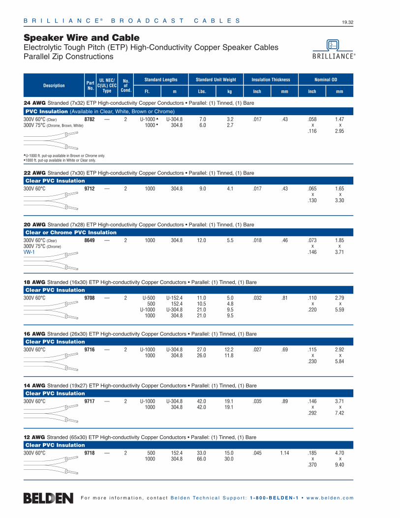
24 AWG Stranded (7x32) ETP High-conductivity Copper Conductors • Parallel: (1) Tinned, (1) Bare
PVC Insulation (Available in Clear, White, Brown or Chrome)
300V 60°C (Clear) 8782 — 2 U-1000 U-304.8 7.0 3.2 .017 .43 .058 1.47300V 75°C (Chrome, Brown, White) 1000 304.8 6.0 2.7 x x
.116 2.95
U-1000 ft. put-up available in Brown or Chrome only.1000 ft. put-up available in White or Clear only.
22 AWG Stranded (7x30) ETP High-conductivity Copper Conductors • Parallel: (1) Tinned, (1) Bare
Clear PVC Insulation300V 60°C 9712 — 2 1000 304.8 9.0 4.1 .017 .43 .065 1.65
x x.130 3.30
20 AWG Stranded (7x28) ETP High-conductivity Copper Conductors • Parallel: (1) Tinned, (1) Bare
Clear or Chrome PVC Insulation300V 60°C (Clear) 8649 — 2 1000 304.8 12.0 5.5 .018 .46 .073 1.85300V 75°C (Chrome) x xVW-1 .146 3.71
18 AWG Stranded (16x30) ETP High-conductivity Copper Conductors • Parallel: (1) Tinned, (1) Bare
Clear PVC Insulation300V 60°C 9708 — 2 U-500 U-152.4 11.0 5.0 .032 .81 .110 2.79
500 152.4 10.5 4.8 x xU-1000 U-304.8 21.0 9.5 .220 5.59
1000 304.8 21.0 9.5
16 AWG Stranded (26x30) ETP High-conductivity Copper Conductors • Parallel: (1) Tinned, (1) Bare
Clear PVC Insulation300V 60°C 9716 — 2 U-1000 U-304.8 27.0 12.2 .027 .69 .115 2.92
1000 304.8 26.0 11.8 x x.230 5.84
14 AWG Stranded (19x27) ETP High-conductivity Copper Conductors • Parallel: (1) Tinned, (1) Bare
Clear PVC Insulation300V 60°C 9717 — 2 U-1000 U-304.8 42.0 19.1 .035 .89 .146 3.71
1000 304.8 42.0 19.1 x x.292 7.42
12 AWG Stranded (65x30) ETP High-conductivity Copper Conductors • Parallel: (1) Tinned, (1) Bare
Clear PVC Insulation300V 60°C 9718 — 2 500 152.4 33.0 15.0 .045 1.14 .185 4.70
1000 304.8 66.0 30.0 x x.370 9.40
F o r m o r e i n f o r m a t i o n , c o n t a c t B e l d e n Te c h n i c a l S u p p o r t : 1 - 8 0 0 - B E L D E N - 1 • w w w . b e l d e n . c o m
B R I L L I A N C E ® B R O A D C A S T C A B L E S 19.32
Speaker Wire and CableElectrolytic Tough Pitch (ETP) High-Conductivity Copper Speaker CablesParallel Zip Constructions
UL NEC/C(UL) CEC
Type
Part No.
No.of
Cond. Ft. m
Standard Lengths Standard Unit Weight
Lbs. kg
Insulation Thickness
Inch mmDescription
Inch mm
Nominal OD

B R I L L I A N C E ® B R O A D C A S T C A B L E S 19.33
Speaker Wire and CableElectrolytic Tough Pitch (ETP) High-Conductivity Copper Speaker CablesOpen Twisted Construction
19•
Brill
ianc
e®Br
oadc
ast
F o r m o r e i n f o r m a t i o n , c o n t a c t B e l d e n Te c h n i c a l S u p p o r t : 1 - 8 0 0 - B E L D E N - 1 • w w w . b e l d e n . c o m
22 AWG Stranded (7x30) ETP High-conductivity Copper Conductors • Cabled: (1) Tinned, (1) Bare
PVC Insulation • (Color Code: White)
UL Listed. Wires Misc. 9151 — 2 U-1000 U-304.8 7.0 3.2 .012 .30 .108 2.7490V 90°CVW-1
18 AWG Stranded (7x26) ETP High-conductivity Tinned Copper Conductors • Cabled
PVC Insulation • (Color Code: Black, Natural)
UL AWM Style 1007 8460 — 2 U-1000 U-304.8 18.0 8.2 .020 .51 .180 4.57(300V 80°C) 1000 304.8 18.0 8.2VW-1
18 AWG Stranded (19x30) ETP High-conductivity Bare Copper Conductors • Cabled
Plenum • Flamarrest® Insulation • (Color Code: Black, Natural)
75°C 1863A NEC: 2 1000 304.8 19.0 8.6 .022 .56 .178 4.52CL2P
16 AWG Stranded (19x29) ETP High-conductivity Tinned Copper Conductors • Cabled
PVC Insulation • (Color Code: Black & Natural for 8470; Black & Orange for 9497)
UL AWM Style 1007 8470 — 2 500 152.4 13.0 5.9 .023 .58 .210 5.33(300V 80°C) U-1000 U-304.8 26.0 11.8VW-1 1000 304.8 26.0 11.8
9497 — 2 1000 304.8 30.0 13.6 .023 .58 .210 5.33
16 AWG Stranded (19x29) ETP High-conductivity Bare Copper Conductors • Cabled
Plenum • Flamarrest Insulation • (Color Code: Black, Natural)
75°C 1862A NEC: 2 1000 304.8 26.0 11.8 .022 .56 .202 5.13CL2P
UL NEC/C(UL) CEC
Type
Part No.
No.of
Cond. Ft. m
Standard Lengths Standard Unit Weight
Lbs. kg
Insulation Thickness
Inch mmDescription
Inch mm
Nominal OD

B R I L L I A N C E ® B R O A D C A S T C A B L E S 19.34
Speaker Wire and CableElectrolytic Tough Pitch (ETP) High-Conductivity Copper Speaker CablesOpen Twisted Construction
F o r m o r e i n f o r m a t i o n , c o n t a c t B e l d e n Te c h n i c a l S u p p o r t : 1 - 8 0 0 - B E L D E N - 1 • w w w . b e l d e n . c o m
14 AWG Stranded (19x27) ETP High-conductivity Bare Copper Conductors • Cabled
Plenum • Flamarrest® Insulation • (Color Code: Black, Natural)
150V RMS 75°C, 1861A NEC: 2 1000 304.8 36.0 16.3 .022 .56 .236 5.99CL2P
12 AWG Stranded (19x25) ETP High-conductivity Bare Copper Conductors • Cabled
Plenum • Flamarrest Insulation • (Color Code: Black, Natural)
150V RMS 75°C, 1860A NEC: 2 1000 304.8 58.0 26.4 .022 .56 .270 6.86CL2P
UL NEC/C(UL) CEC
Type
Part No.
No.of
Cond. Ft. m
Standard Lengths Standard Unit Weight
Lbs. kg
Insulation Thickness
Inch mmDescription
Inch mm
Nominal OD

B R I L L I A N C E ® B R O A D C A S T C A B L E S 19.35
Speaker Wire and CableElectrolytic Tough Pitch (ETP) High-Conductivity Copper Speaker CablesTwisted Jacketed Construction
19•
Brill
ianc
e®Br
oadc
ast
F o r m o r e i n f o r m a t i o n , c o n t a c t B e l d e n Te c h n i c a l S u p p o r t : 1 - 8 0 0 - B E L D E N - 1 • w w w . b e l d e n . c o m
22 AWG Stranded (7x30) Tinned Copper Conductors • Conductors Cabled
PVC Insulation • Chrome PVC Jacket300V RMS 60°C 8442 NEC: 2 Black, 100 30.5 2.4 1.0 .015 .38 .025 .64 .170 4.32
CMG Red U-500 U-152.4 7.5 3.4CEC: 500 152.4 7.5 3.4
CMG FT4 U-1000 U-304.8 15.0 6.81000 304.8 15.0 6.8
10000 3048.0 150.0 68.2
20 AWG Stranded (7x28) Tinned Copper Conductors • Twisted Pair
PVC Insulation • Chrome PVC Jacket300V RMS 80°C 8205 NEC: 2 Black, 100 30.5 2.6 1.2 .013 .33 .025 .64 .180 4.57
CMG Red U-500 U-152.4 9.0 4.1CEC: 500 152.4 9.0 4.1
CMG FT4 U-1000 U-304.8 17.0 7.71000 304.8 18.0 8.2
18 AWG Stranded (7x26) Tinned Copper Conductors • Twisted Pair
PVC Insulation • Chrome PVC Jacket 300V RMS 80°C 8461 NEC: 2 Black, 100 30.5 3.2 1.4 .022 .56 .028 .71 .234 5.94
CMG White U-500 U-152.4 13.5 6.1CEC: 500 152.4 13.5 6.1
CMG FT4 U-1000 U-304.8 26.0 11.81000 304.8 27.0 12.2
16 AWG Stranded (19x29) Tinned Copper Conductors • Twisted Pair
PVC Insulation • Chrome PVC JacketUL AWM Style 2598 8471 NEC: 2 Black, U-500 U-152.4 20.0 9.1 .023 .58 .032 .81 .274 6.96(300V 60°C) CMG White 500 152.4 20.0 9.1(80°C non-UL) CEC: U-1000 U-304.8 38.0 17.2
CMG FT4 1000 304.8 40.0 18.2
14 AWG Stranded (42x30) Tinned Copper Conductors • Twisted Pair
PVC Insulation • Chrome PVC JacketUL AWM Style 2587 8473 NEC: 2 Black, U-500 U-152.4 29.0 13.2 .031 .79 .032 .81 .340 8.64(600V 90°C) CL3 White 500 152.4 30.5 13.9
CEC: 1000 304.8 58.0 26.4FAS 90 FT4
See NEC Guidelines for applicable CL3 voltage ratings (300V RMS).
12 AWG Stranded (65x30) Tinned Copper Conductors • Twisted Pair
PVC Insulation • Chrome PVC JacketUL AWM Style 2587 8477 NEC: 2 Black, U-500 U-152.4 41.5 18.8 .032 .81 .035 .89 .386 9.80(600V 90°C) CL3R White 500 152.4 43.5 19.7
1000 304.8 85.0 38.6
See NEC Guidelines for applicable CL3 voltage ratings (300V RMS).
UL NEC/C(UL) CEC
Type
Part No.
No.of
Cond. Ft. m
Standard Lengths StandardUnit Weight
Lbs. kg
InsulationThickness
Inch mmDescription Color
Code
JacketThickness
Inch mm
Nominal OD
Inch mm
For Plenum versions of 8442, see 88442 or 82442.

B R I L L I A N C E ® B R O A D C A S T C A B L E S 19.36
Speaker Wire and CableLow-Capacitance Oxygen-Free, High-Conductivity (OFHC) Speaker CableTwisted Jacketed Construction
F o r m o r e i n f o r m a t i o n , c o n t a c t B e l d e n Te c h n i c a l S u p p o r t : 1 - 8 0 0 - B E L D E N - 1 • w w w . b e l d e n . c o m
Color Code Chart
Cond. Color1 Black2 Red3 White4 Green
Nominal Capacitance*
pF/Ft. pF/m
UL NEC/C(UL) CEC
Type
PartNo.
No.of
Cond. Ft. m
Standard Lengths StandardUnit Weight
Lbs. kg
InsulationThickness
InchDescription
JacketThickness Nominal OD
Inch mmmm Inch mm
Low Cap • 16 AWG Stranded (65x34) Oxygen-free High-Conductivity Bare Copper Conductors • Conductors Cabled • Unshielded
Polyolefin Insulation • PVC Jacket (Available in Black, White, Gray, Blue or Green)1307A NEC: 2 U-500 U-152.4 15.0 6.8 .013 .32 .022 .56 .210 5.33 19.9 65.3u CMR, CL3R 1000 † 304.8 29.0 13.2
CEC:CMG FT4
Suitable for Direct Burial applications. White and Black jackets are Sunlight-resistant.
1308A NEC: 4 U-500 U-152.4 26.5 12.0 .013 .32 .026 .66 .270 6.86 19.9 65.3u CMR, CL3R 1000 † 304.8 54.0 24.5
CEC:CMG FT4
Suitable for Direct Burial applications. White and Black jackets are Sunlight-resistant.
Low Cap • 14 AWG Stranded (105x34) Oxygen-free High-Conductivity Bare Copper Conductors • Conductors Cabled • Unshielded
Polyolefin Insulation • PVC Jacket (Available in Black, White, Gray, Blue or Green)For Audio Use Only 1309A NEC: 2 U-500 U-152.4 22.5 10.2 .016 .39 .027 .69 .264 6.71 20.5 67.3
u CMR, CL3R 1000 † 304.8 46.0 20.9CEC:
CMG FT4
Suitable for Direct Burial applications. White and Black jackets are Sunlight-resistant.
For Audio Use Only 1310A NEC: 4 U-500 U-152.4 41.5 18.8 .016 .39 .033 .94 .319 8.10 20.5 67.3u CMR, CL3R 1000 † 304.8 84.0 38.1
CEC:CMG FT4
Suitable for Direct Burial applications. White and Black jackets are Sunlight-resistant.
Low Cap • 12 AWG Stranded (168x34) Oxygen-free High-Conductivity Bare Copper Conductors • Conductors Cabled • Unshielded
Polyolefin Insulation • PVC Jacket (Available in Black, White or Gray)For Audio Use Only 1311A NEC: 2 U-500 U-152.4 36.5 16.6 .018 .46 .036 .91 .352 8.94 22.3 73.2
u CMR, CL3R 500 152.4 36.5 16.6CEC: 1000 † 304.8 74.0 33.6
CMG FT4
Suitable for Direct Burial applications. White and Black jackets are Sunlight-resistant.
For Audio Use Only 1312A NEC: 4 500 152.4 66.5 30.2 .018 .46 .043 1.09 .423 10.74 22.3 73.2u CMR, CL3R 1000 † 304.8 132.0 59.9
CEC:CMG FT4
Suitable for Direct Burial applications. White and Black jackets are Sunlight-resistant.
Low Cap • 10 AWG Stranded (259x34) Oxygen-free High-Conductivity Bare Copper Conductors • Conductors Cabled
Polyolefin Insulation • PVC Jacket (Available in Black, White or Gray)For Audio Use Only 1313A NEC: 2 500 152.4 55.0 25.0 .019 .48 .044 1.12 .428 10.87 23.2 76.1
u CMR, CL3R 1000 † 304.8 109.0 49.5CEC:
CMG FT4
Suitable for Direct Burial applications. White and Black jackets are Sunlight-resistant.
OFHC = Oxygen-Free High-Conductivity
*Capacitance between conductors.†1000 ft. put-ups not available in Blue or Green.
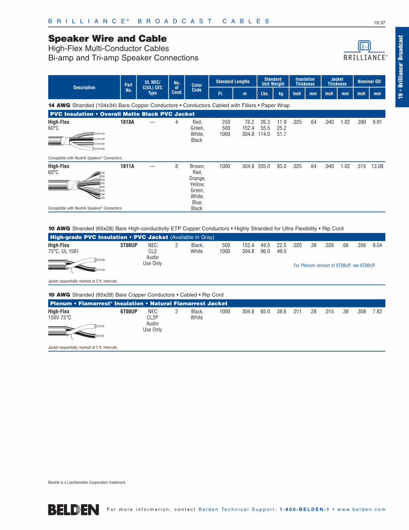
B R I L L I A N C E ® B R O A D C A S T C A B L E S 19.37
Speaker Wire and CableHigh-Flex Multi-Conductor CablesBi-amp and Tri-amp Speaker Connections
19•
Brill
ianc
e®Br
oadc
ast
F o r m o r e i n f o r m a t i o n , c o n t a c t B e l d e n Te c h n i c a l S u p p o r t : 1 - 8 0 0 - B E L D E N - 1 • w w w . b e l d e n . c o m
UL NEC/C(UL) CEC
Type
Part No.
No.of
Cond. Ft. m
Standard Lengths StandardUnit Weight
Lbs. kg
InsulationThickness
Inch mmDescription Color
Code
JacketThickness
Inch mm
Nominal OD
Inch mm
14 AWG Stranded (104x34) Bare Copper Conductors • Conductors Cabled with Fillers • Paper Wrap
PVC Insulation • Overall Matte Black PVC JacketHigh-Flex 1810A — 4 Red, 250 76.2 26.3 11.9 .025 .64 .040 1.02 .390 9.9160°C Green, 500 152.4 55.5 25.2
White, 1000 304.8 114.0 51.7Black
Compatible with Neutrik Speakon® Connectors.
High-Flex 1811A — 8 Brown, 1000 304.8 205.0 93.0 .025 .64 .040 1.02 .515 13.0860°C Red,
Orange,Yellow,Green,White,Blue,
Compatible with Neutrik Speakon® Connectors. Black
10 AWG Stranded (65x28) Bare High-conductivity ETP Copper Conductors • Highly Stranded for Ultra Flexibility • Rip Cord
High-grade PVC Insulation • PVC Jacket (Available in Gray)
High-Flex 5T00UP NEC: 2 Black, 500 152.4 49.5 22.5 .020 .38 .026 .66 .356 9.0475°C, UL 1581 CL2 White 1000 304.8 96.0 49.5
AudioUse Only
Jacket sequentially marked at 2 ft. intervals.
10 AWG Stranded (65x28) Bare Copper Conductors • Cabled • Rip Cord
Plenum • Flamarrest® Insulation • Natural Flamarrest JacketHigh-Flex 6T00UP NEC: 2 Black, 1000 304.8 85.0 38.6 .011 .28 .015 .38 .308 7.82150V 75°C CL2P White
AudioUse Only
Jacket sequentially marked at 2 ft. intervals.
Neutrik is a Liechtenstein Corporation trademark.
For Plenum version of 5T00UP, see 6T00UP.

B R I L L I A N C E ® B R O A D C A S T C A B L E S 19.38
Special Application Audio, Communication and Instrumentation CableAudio Connecting Cables and Dual Channel Audio Cables
F o r m o r e i n f o r m a t i o n , c o n t a c t B e l d e n Te c h n i c a l S u p p o r t : 1 - 8 0 0 - B E L D E N - 1 • w w w . b e l d e n . c o m
Ft.
StandardLengths
25 AWG Stranded (7x33) Conductor • (3) TC, (4) TCCS • Double Beldfoil® Shield (100% Coverage) • 26 AWG Stranded TC Drain Wire
FPE Insulation • Chrome PVC JacketMiniature 8417 — 1 — 250 76.2 3.3 1.5 .020 .51 .026 .66 .140 3.56 29 9580°C
25 AWG Stranded (7x33) Conductor • (3) TC, (4) TCCS • Tinned Copper Spiral Wrapped Shield (86% Coverage)
FPE Insulation • Chrome PVC JacketLow-Capacitance 8421 — 1 — 250 76.2 4.5 2.0 .051 1.30 .023 .58 .180 4.57 16 5380°C
24 AWG Uni-strand (7x32) Tinned Copper Conductor • Beldfoil Shield (100% Coverage)
Flame-retardant Polypropylene Insulation • Black PVC JacketUL AWM Style 1770 9264 — 1 — 1000 304.8 14.0 6.4 .027 .69 .020 .51 .122 3.10 30 99(300V 80°C) x xVW-1 .146 3.71
Nominal impedance: 50 ohms.Tear-drop, machine strippable coaxial cable.
Dual Channel • 30 AWG Stranded (7x38) TCCS Conductors • Individual Tinned Copper Spiral Wrapped Shield (85% Coverage)
FPE Insulation • Black PVC Jacket • Polarity RibbedLow-Capacitance 9454 — 2 — 100 30.5 3.5 1.6 .049 1.24 .020 .51 .160 4.06 12 3970°C x x each
.320 8.13 channel
Stereo connecting cable
Dual Channel • 25 AWG Stranded (7x38) Conductors • (3) TC, (4) TCCS • Individual TC Spiral Wrapped Shield (90% Coverage)
Polyethylene Insulation • Gray PVC Jacket • Polarity Rib on Red Conductor80°C 8416 — 2 — 250 76.2 4.8 2.2 .018 .46 .020 .51 .106 2.69 36 118
x x each
.213 5.41 channel
For use with head sets, stereo and language labs.
FPE = Foam Polyethylene • TC = Tinned Copper • TCCS = Tinned Copper-covered Steel
*Capacitance between conductors.
UL NEC/C(UL) CEC
Type
Part No.
No.of
Cond.Description Color
Codem
StandardUnit Weight
InsulationThickness
JacketThickness
Nominal OD
NominalCapacitance
Lbs. kg Inch mm Inch mm Inch mm pF/Ft.* pF/m*
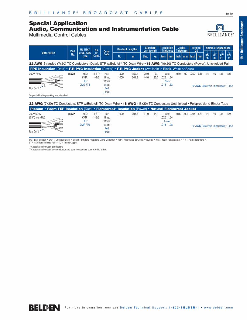
B R I L L I A N C E ® B R O A D C A S T C A B L E S 19.39
Special Application Audio, Communication and Instrumentation CableMultimedia Control Cables
19•
Brill
ianc
e®Br
oadc
ast
F o r m o r e i n f o r m a t i o n , c o n t a c t B e l d e n Te c h n i c a l S u p p o r t : 1 - 8 0 0 - B E L D E N - 1 • w w w . b e l d e n . c o m
22 AWG Stranded (7x30) TC Conductors (Data), STP w/Beldfoil®, TC Drain Wire • 18 AWG (16x30) TC Conductors (Power), Unshielded Pair
FPE Insulation (Data) • F-R PVC Insulation (Power) • F-R PVC Jacket (Available in Black, White or Aqua)
300V 75°C 1502R NEC: 1 STP Pair: 500 152.4 20.0 9.1 Data: .039 .99 .250 6.35 14 46 38 125CMR +2/C Blue, 1000 304.8 44.0 20.0 .025 .64CEC: White Power:
CMG FT4 Cond.: .013 .33Red,
BlackSequential footing marking every two feet.
22 AWG (7x30) TC Conductors, STP w/Beldfoil, TC Drain Wire • 18 AWG (16x30) TC Conductors Unshielded • Polypropylene Binder Tape
Plenum • Foam FEP Insulation (Data) • Flamarrest® Insulation (Power) • Natural Flamarrest Jacket 300V 60°C 1502P NEC: 1 STP Pair: 1000 304.8 31.0 14.1 Data: .015 .381 .205 5.21 14 46 38 125(75°C non-UL) CMP +2/C Blue, .025 .64
CEC: White Power:CMP FT6 Cond.: .011 .28
Red,Black
BC = Bare Copper • DCR = DC Resistance • EPDM = Ethylene Propylene Diene Monomer • FEP = Fluorinated Ethylene Propylene • FPE = Foam Polyethylene • F -R = Flame-retardant •STP = Shielded Twisted Pair • TC = Tinned Copper
*Capacitance between conductors.**Capacitance between one conductor and other conductors connected to shield.
UL NEC/C(UL) CEC
Type
Part No.
No.of
Cond. Ft. m
Standard Lengths StandardUnit Weight
Lbs. kg
InsulationThickness
Inch mmDescription Color
Code
JacketThickness
Inch mm
Nominal OD
Inch mm
Nominal Capacitance
*pF/Ft.
*pF/m
**pF/Ft.
**pF/m
Rip Cord
Rip Cord
22 AWG Data Pair Impedance: 100Ω
22 AWG Data Pair Impedance: 100Ω

Mic • 20 AWG Stranded (19x32) High-conductivity TC Conductors, Cabled • Rayon Braid • TC Braid Shield (84% Coverage)
Polyethylene Insulation • Chrome PVC JacketLow-Impedance 8405 — 5 Black, 250 46.2 14.8 6.7 .016 .41 .035 .89 .281 7.14 23 76 40 131UL AWM Style 2094 Clear, 500 152.4 29.5 13.4(300V 60°C) Green, 1000 304.8 63.0 28.6VW-1 Red,
Blue
Mic • 20 AWG Stranded (26x34) High-conductivity TC Conductors, Cabled • Cotton Wrap • Rayon Braid • TC Braid Shield (85% Coverage)
Rubber Insulation • Black EPDM Rubber JacketLow-Impedance 8425 — 5 Blue, 100 30.5 7.8 3.5 .023 .58 .031 .79 .318 8.08 30 98 55 180600V RMS 90°C Orange, 250 46.2 17.3 7.8(60°C non-UL) Black,
White,Brown
8426 — 6 (Same as 8425) 100 30.5 9.0 4.1 .023 .58 .037 .94 .342 8.69 30 98 55 180+ 250 46.2 21.0 9.5
Green
8427 — 7 (Same as 8426) 100 30.5 9.8 4.5 .023 .58 .041 1.04 .355 9.02 30 98 55 180+ 250 46.2 22.3 10.1
Red
8418 — 8 (Same as 8427) 100 30.5 11.0 5.0 .023 .58 .037 .94 .381 9.68 30 98 55 180+ 250 46.2 25.0 11.3
Yellow
EPDM = Ethylene Propylene Diene Monomer • TC = Tinned Copper
*Capacitance between conductors.**Capacitance between one conductor and other conductors connected to shield.
B R I L L I A N C E ® B R O A D C A S T C A B L E S 19.40
Special Application Audio, Communication and Instrumentation CableMicrophone/Musical Instrument Cables
F o r m o r e i n f o r m a t i o n , c o n t a c t B e l d e n Te c h n i c a l S u p p o r t : 1 - 8 0 0 - B E L D E N - 1 • w w w . b e l d e n . c o m
UL NEC/C(UL) CEC
Type
Part No.
No.of
Cond. Ft. m
Standard Lengths StandardUnit Weight
Lbs. kg
InsulationThickness
Inch mmDescription Color
Code
JacketThickness
Inch mm
Nominal OD
Inch mm
Nominal Capacitance
*pF/Ft.
*pF/m
**pF/Ft.
**pF/m

B R I L L I A N C E ® B R O A D C A S T C A B L E S 19.41
19•
Brill
ianc
e®Br
oadc
astStandard Analog Video Cable
75 Ohm Miniature Coax
F o r m o r e i n f o r m a t i o n , c o n t a c t B e l d e n Te c h n i c a l S u p p o r t : 1 - 8 0 0 - B E L D E N - 1 • w w w . b e l d e n . c o m
dB/100m
30 AWG Stranded (7x38) .012″ Tinned Copper Conductor • Tinned Copper Braid Shield (89% Coverage)
Foam HDPE Insulation • Black PVC JacketUL AWM 9221 — 100 30.5 1.5 1.0 30 AWG .058 1.47 TC Braid .097 2.46 75 78% 17.3 56.8Style 1375 U-500 U-152.4 4.0 1.8 (7x38) 89% Shield(30V 60°C) 500 152.4 4.0 1.8 .012″ Coverage
TC 11.7Ω/M′100.0Ω/M′ 38.4Ω/km328.0Ω/km
27 AWG Stranded (7x35) .017″ Bare Copper-covered Steel Conductor • Tinned Copper Braid Shield (93% Coverage)
Polyethylene Insulation • Black PVC JacketUL AWM 8218 — U-500 U-152.4 8.5 3.9 27 AWG .100 2.54 TC Braid .150 3.81 75 66% 20.5 67.3Style 1354 500 152.4 8.0 3.6 (7x35) 93% Shield(30V 60°C) U-1000 U-304.8 16.0 7.3 .017″ Coverage(1700V non-UL) 1000 304.8 14.0 6.4 BCCS 5.7Ω/M′
120.0Ω/M′ 18.7Ω/km393.7Ω/km
Miniature • 25 AWG Solid .018″ Tinned Copper Conductors • Duobond® (100% Coverage) + TC Braid Shield (95% Coverage)
Gas-injected Foam HDPE Insulation • Black PVC Jacket1281R NEC: 1 1000 304.8 8.0 3.6 25 AWG .074 1.88 Duobond .114 2.90 75 80% 17.0 55.8u CMR (solid) (100%)
CEC: .018″ TC + TC BraidCMG 34.0Ω/M′ 5.4Ω/M′
111.6Ω/km 17.7Ω/km
Plenum • FPFA Insulation • Black Flamarrest® Jacket1282P NEC: 1 1000 304.8 10.0 4.5 25 AWG .074 1.88 Duobond .114 2.90 75 81% 17.0 55.8u CMP (solid) (100%)
CEC: .018″ TC + TC Braid CMP FT6 31.8Ω/M′ 5.8Ω/M′
104.3Ω/km 19.0Ω/km
BCCS = Bare Copper-covered Steel • DCR = DC Resistance • FPFA = Foam Perfluoroalkoxy • HDPE = High-density Polyethylene • TC = Tinned Copper
1 .7 2.34 1.3 4.35 1.6 5.2
10 2.2 7.250 5.1 16.7
100 7.3 23.9200 10.5 34.4400 15.5 50.9
1000 26.6 87.3
1 1.2 3.910 2.4 7.950 4.2 13.8
100 5.7 18.7200 8.3 27.2400 12.1 39.7700 16.5 54.1900 19.0 62.3
1000 20.0 65.6
ShieldingMaterialsNom. DCR
Nom.Imp.(Ω)
Insulation Diameter Nominal OD
Inch mm Inch mm
Conductor(stranding)DiameterNom. DCR
StandardUnit WeightStandard Lengths
Lbs. kgFt. m
UL NEC/C(UL) CEC
Type
PartNo.
MHz dB/100 Ft.
Nominal Attenuation
Nominal Capacitance
pF/mpF/Ft.
Nom.Vel.of
Prop.Description
Belden standard video cables are typically used in non-critical videoapplications such as video equipment rack wiring, closed circuit TV(CCTV), master antenna TV(MATV) and color or monochrome videomonitor hook-ups. Applications such as these do not require PrecisionVideo coaxes which have extremely tight electrical tolerances. (See Precision Video cables, pages 19.49 through 19.58.)
Video coax cables have a characteristic impedance of 75 ohms.This value was not chosen arbitrarily. Physics shows that optimumattenuation characteristics occur at 77 ohms. Materials and designlead to the selection of 75 ohms as the optimum compromise for low power applications.
Standard video coaxes are available in both solid and strandeddesigns. Stranded designs are recommended for flexing applications such as interconnection of CCTV cameras with pan and tilt capabilities, or remote camera hook-ups where thecable is constantly being spooled and despooled from a reel.Belden’s Brilliance high-flex part no. 8241F is ideal for these types of applications.
Sweep Tested 5 MHZ to 850 MHz.Guaranteed Return Loss –20dB Max.
See page 19.71 for Bundled versions.
1 .4 1.3 5 .9 3.0
50 3.7 12.1 100 5.0 16.4 200 7.0 23.0 400 10.0 32.8 700 14.5 47.6 900 17.0 55.8
1000 17.5 57.4 3000 37.0 121.4
Sweep Tested 5 MHZ to 850 MHz.Guaranteed Return Loss –20dB Max.
See page 19.71 for Bundled versions.
1 .5 1.7 5 1.2 3.8
50 3.7 12.1 100 4.9 16.1 200 6.7 22.0 400 9.5 31.2 700 13.4 44.0 900 15.0 49.2
1000 15.8 51.8 3000 31.2 102.4

B R I L L I A N C E ® B R O A D C A S T C A B L E S 19.42
Standard Analog Video Cable75 Ohm High-Frequency CablesConformable® Coax Cable
F o r m o r e i n f o r m a t i o n , c o n t a c t B e l d e n Te c h n i c a l S u p p o r t : 1 - 8 0 0 - B E L D E N - 1 • w w w . b e l d e n . c o m
29 AWG Solid .011″ Silver-coated Copper-covered Steel Conductor • Copper-Tin Composite Shield (100% Coverage)
TFE Teflon® Insulation • UnjacketedUL AWM 1672A* — 500 †† 152.4 7.5 3.4 29 AWG .062 1.57 CT .087 2.21 75 69.5% 19.5 64.0Style 10245 1000 †† 304.8 14.0 6.4 (solid) Composite(30V 105°C) .011″ 100% Shield(1500V RMS 200°C non-UL) SCCCS Coverage
205.0Ω/M′ 10.0Ω/M′672.4Ω/km 33.5Ω/km
TFE Teflon Insulation • PVC Jacket (Black or Clear)UL AWM 1672J* — 100 † 30.5 3.1 1.4 29 AWG .062 1.57 CT .127 3.23 75 69.5% 19.5 64.0Style 10245 500 † 152.4 9.5 4.3 (solid) Composite(30V 105°C) 1000 †† 304.8 17.0 7.7 .011″ 100% Shield(1500V RMS 200°C non-UL) SCCCS Coverage
205.0Ω/M′ 10.0Ω/M′672.4Ω/km 33.5Ω/km
100 ft. put-up available in Clear only.
29 AWG Solid .011″ Silver-plated Copper Conductor • Copper-Tin Composite Shield (100% Coverage)
TFE Teflon Insulation • UnjacketedUL AWM 1672B* — 100 † 30.5 2.5 1.1 29 AWG .062 1.57 CT .087 2.21 75 69.5% 19.5 64.0Style 10245 500 † 152.4 7.5 3.4 (solid) Composite(30V 105°C) 1000 † 304.8 14.0 6.4 .011″ 100% Shield(1500V RMS 200°C non-UL) SPC Coverage
11.0Ω/M′ 10.0Ω/M′36.9Ω/km 33.5Ω/km
Non-ferrous design
CT = Copper Tin • DCR = DC Resistance • SCCCS = Silver-coated Copper-covered Steel • SPC = Silver-plated Copper
Contact the Belden Customer Service Department for a Comprehensive Connector Cross Reference. 1-800-BELDEN-1.
*Protected by one or more of U.S. Patent Nos. 4,694,122 and 5,292,001. Patent held in the U.S., Singapore, Australia, Germany, France and England. Patent pending in Japan.†May contain more than one piece. Minimum length of any one piece is 25 ft.††500 ft. put-up: Exact 5 pieces (maximum), 50 feet minimum length
1000 ft. put-up: Exact 8 pieces (maximum), 50 feet minimum length
1 1.6 5.310 1.8 5.950 4.1 13.5
100 6.5 21.3200 9.0 29.5400 12.8 42.0700 18.0 59.1
1000 22.1 72.5
1 1.2 3.910 1.8 5.950 4.1 13.5
100 6.5 21.3200 9.0 29.5400 12.8 42.0700 18.0 59.1
1000 22.1 72.5
1 1.6 5.310 1.8 5.950 4.1 13.5
100 6.5 21.3200 9.0 29.5400 12.8 42.0700 18.0 59.1
1000 22.1 72.5
Teflon is a DuPont trademark.
ShieldingMaterialsNom. DCR
Nom.Imp.(Ω)
Insulation Diameter Nominal OD
Inch mm Inch mm
Conductor(stranding)DiameterNom. DCR
StandardUnit WeightStandard Lengths
Lbs. kgFt. m
UL NEC/C(UL) CEC
Type
PartNo.
MHz dB/100 Ft.
dB/100m
Nominal Attenuation
Nominal Capacitance
pF/mpF/Ft.
Nom.Vel.of
Prop.Description
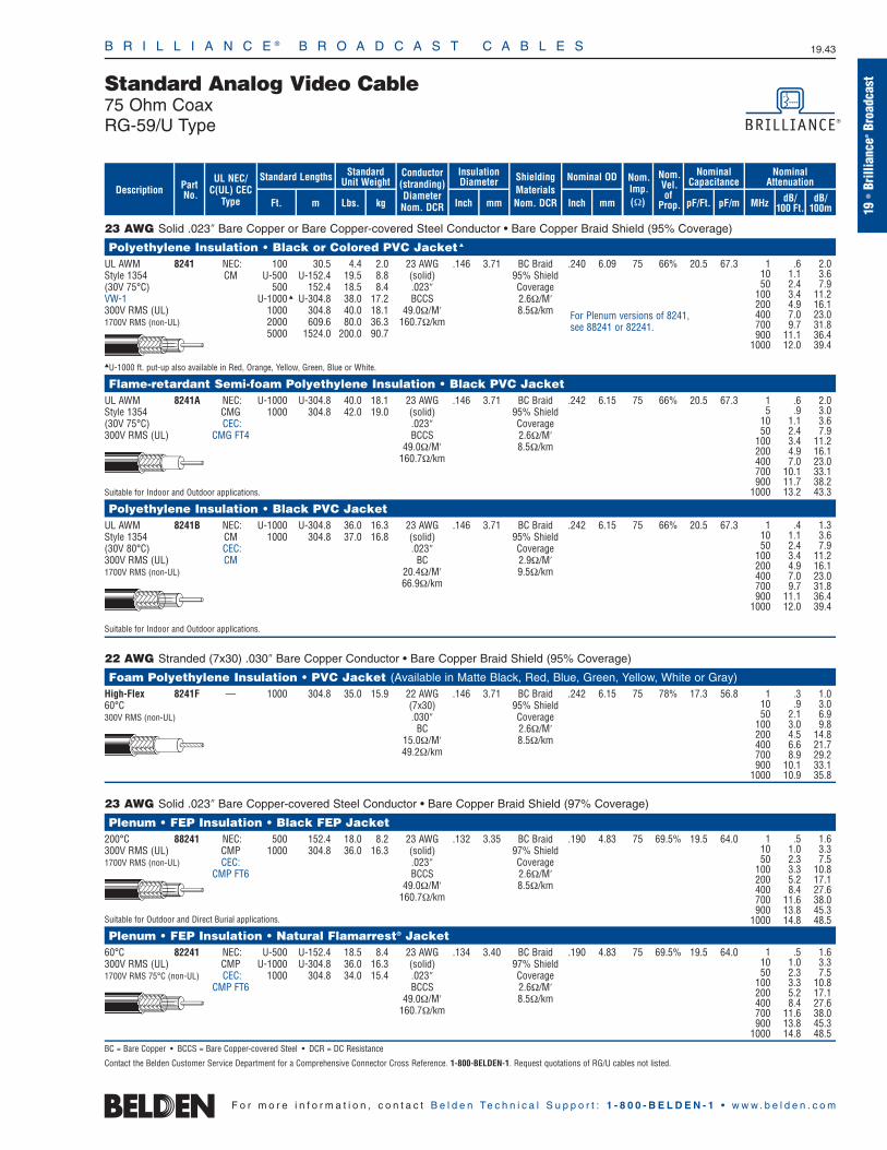
B R I L L I A N C E ® B R O A D C A S T C A B L E S 19.43
19•
Brill
ianc
e®Br
oadc
astStandard Analog Video Cable
75 Ohm CoaxRG-59/U Type
F o r m o r e i n f o r m a t i o n , c o n t a c t B e l d e n Te c h n i c a l S u p p o r t : 1 - 8 0 0 - B E L D E N - 1 • w w w . b e l d e n . c o m
23 AWG Solid .023″ Bare Copper or Bare Copper-covered Steel Conductor • Bare Copper Braid Shield (95% Coverage)
Polyethylene Insulation • Black or Colored PVC Jacket
UL AWM 8241 NEC: 100 30.5 4.4 2.0 23 AWG .146 3.71 BC Braid .240 6.09 75 66% 20.5 67.3Style 1354 CM U-500 U-152.4 19.5 8.8 (solid) 95% Shield(30V 75°C) 500 152.4 18.5 8.4 .023″ CoverageVW-1 U-1000 U-304.8 38.0 17.2 BCCS 2.6Ω/M′300V RMS (UL) 1000 304.8 40.0 18.1 49.0Ω/M′ 8.5Ω/km1700V RMS (non-UL) 2000 609.6 80.0 36.3 160.7Ω/km
5000 1524.0 200.0 90.7
U-1000 ft. put-up also available in Red, Orange, Yellow, Green, Blue or White.
Flame-retardant Semi-foam Polyethylene Insulation • Black PVC JacketUL AWM 8241A NEC: U-1000 U-304.8 40.0 18.1 23 AWG .146 3.71 BC Braid .242 6.15 75 66% 20.5 67.3Style 1354 CMG 1000 304.8 42.0 19.0 (solid) 95% Shield(30V 75°C) CEC: .023″ Coverage300V RMS (UL) CMG FT4 BCCS 2.6Ω/M′
49.0Ω/M′ 8.5Ω/km160.7Ω/km
Suitable for Indoor and Outdoor applications.
Polyethylene Insulation • Black PVC JacketUL AWM 8241B NEC: U-1000 U-304.8 36.0 16.3 23 AWG .146 3.71 BC Braid .242 6.15 75 66% 20.5 67.3Style 1354 CM 1000 304.8 37.0 16.8 (solid) 95% Shield(30V 80°C) CEC: .023″ Coverage300V RMS (UL) CM BC 2.9Ω/M′1700V RMS (non-UL) 20.4Ω/M′ 9.5Ω/km
66.9Ω/km
Suitable for Indoor and Outdoor applications.
22 AWG Stranded (7x30) .030″ Bare Copper Conductor • Bare Copper Braid Shield (95% Coverage)
Foam Polyethylene Insulation • PVC Jacket (Available in Matte Black, Red, Blue, Green, Yellow, White or Gray)High-Flex 8241F — 1000 304.8 35.0 15.9 22 AWG .146 3.71 BC Braid .242 6.15 75 78% 17.3 56.860°C (7x30) 95% Shield300V RMS (non-UL) .030″ Coverage
BC 2.6Ω/M′15.0Ω/M′ 8.5Ω/km49.2Ω/km
23 AWG Solid .023″ Bare Copper-covered Steel Conductor • Bare Copper Braid Shield (97% Coverage)
Plenum • FEP Insulation • Black FEP Jacket200°C 88241 NEC: 500 152.4 18.0 8.2 23 AWG .132 3.35 BC Braid .190 4.83 75 69.5% 19.5 64.0300V RMS (UL) CMP 1000 304.8 36.0 16.3 (solid) 97% Shield1700V RMS (non-UL) CEC: .023″ Coverage
CMP FT6 BCCS 2.6Ω/M′49.0Ω/M′ 8.5Ω/km
160.7Ω/km
Suitable for Outdoor and Direct Burial applications.
Plenum • FEP Insulation • Natural Flamarrest® Jacket60°C 82241 NEC: U-500 U-152.4 18.5 8.4 23 AWG .134 3.40 BC Braid .190 4.83 75 69.5% 19.5 64.0300V RMS (UL) CMP U-1000 U-304.8 36.0 16.3 (solid) 97% Shield1700V RMS 75°C (non-UL) CEC: 1000 304.8 34.0 15.4 .023″ Coverage
CMP FT6 BCCS 2.6Ω/M′49.0Ω/M′ 8.5Ω/km
160.7Ω/km
BC = Bare Copper • BCCS = Bare Copper-covered Steel • DCR = DC Resistance
Contact the Belden Customer Service Department for a Comprehensive Connector Cross Reference. 1-800-BELDEN-1. Request quotations of RG/U cables not listed.
1 .6 2.010 1.1 3.650 2.4 7.9
100 3.4 11.2200 4.9 16.1400 7.0 23.0700 9.7 31.8900 11.1 36.4
1000 12.0 39.4
1 .6 2.05 .9 3.0
10 1.1 3.650 2.4 7.9
100 3.4 11.2200 4.9 16.1400 7.0 23.0700 10.1 33.1900 11.7 38.2
1000 13.2 43.3
1 .5 1.610 1.0 3.350 2.3 7.5
100 3.3 10.8200 5.2 17.1400 8.4 27.6700 11.6 38.0900 13.8 45.3
1000 14.8 48.5
1 .5 1.610 1.0 3.350 2.3 7.5
100 3.3 10.8200 5.2 17.1400 8.4 27.6700 11.6 38.0900 13.8 45.3
1000 14.8 48.5
For Plenum versions of 8241, see 88241 or 82241.
1 .4 1.310 1.1 3.650 2.4 7.9
100 3.4 11.2200 4.9 16.1400 7.0 23.0700 9.7 31.8900 11.1 36.4
1000 12.0 39.4
1 .3 1.010 .9 3.050 2.1 6.9
100 3.0 9.8200 4.5 14.8400 6.6 21.7700 8.9 29.2900 10.1 33.1
1000 10.9 35.8
ShieldingMaterialsNom. DCR
Nom.Imp.(Ω)
Insulation Diameter Nominal OD
Inch mm Inch mm
Conductor(stranding)DiameterNom. DCR
StandardUnit WeightStandard Lengths
Lbs. kgFt. m
UL NEC/C(UL) CEC
Type
PartNo.
MHz dB/100 Ft.
dB/100m
Nominal Attenuation
Nominal Capacitance
pF/mpF/Ft.
Nom.Vel.of
Prop.Description
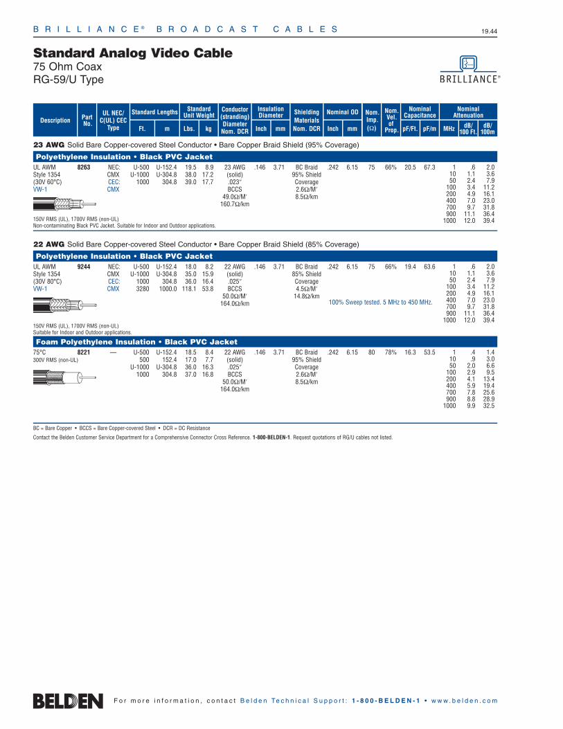
B R I L L I A N C E ® B R O A D C A S T C A B L E S 19.44
Standard Analog Video Cable75 Ohm CoaxRG-59/U Type
F o r m o r e i n f o r m a t i o n , c o n t a c t B e l d e n Te c h n i c a l S u p p o r t : 1 - 8 0 0 - B E L D E N - 1 • w w w . b e l d e n . c o m
23 AWG Solid Bare Copper-covered Steel Conductor • Bare Copper Braid Shield (95% Coverage)
Polyethylene Insulation • Black PVC JacketUL AWM 8263 NEC: U-500 U-152.4 19.5 8.9 23 AWG .146 3.71 BC Braid .242 6.15 75 66% 20.5 67.3Style 1354 CMX U-1000 U-304.8 38.0 17.2 (solid) 95% Shield(30V 60°C) CEC: 1000 304.8 39.0 17.7 .023″ CoverageVW-1 CMX BCCS 2.6Ω/M′
49.0Ω/M′ 8.5Ω/km160.7Ω/km
150V RMS (UL), 1700V RMS (non-UL)Non-contaminating Black PVC Jacket. Suitable for Indoor and Outdoor applications.
22 AWG Solid Bare Copper-covered Steel Conductor • Bare Copper Braid Shield (85% Coverage)
Polyethylene Insulation • Black PVC JacketUL AWM 9244 NEC: U-500 U-152.4 18.0 8.2 22 AWG .146 3.71 BC Braid .242 6.15 75 66% 19.4 63.6Style 1354 CMX U-1000 U-304.8 35.0 15.9 (solid) 85% Shield(30V 80°C) CEC: 1000 304.8 36.0 16.4 .025″ CoverageVW-1 CMX 3280 1000.0 118.1 53.8 BCCS 4.5Ω/M′
50.0Ω/M′ 14.8Ω/km164.0Ω/km
150V RMS (UL), 1700V RMS (non-UL)Suitable for Indoor and Outdoor applications.
Foam Polyethylene Insulation • Black PVC Jacket75°C 8221 — U-500 U-152.4 18.5 8.4 22 AWG .146 3.71 BC Braid .242 6.15 80 78% 16.3 53.5300V RMS (non-UL) 500 152.4 17.0 7.7 (solid) 95% Shield
U-1000 U-304.8 36.0 16.3 .025″ Coverage1000 304.8 37.0 16.8 BCCS 2.6Ω/M′
50.0Ω/M′ 8.5Ω/km164.0Ω/km
BC = Bare Copper • BCCS = Bare Copper-covered Steel • DCR = DC Resistance
Contact the Belden Customer Service Department for a Comprehensive Connector Cross Reference. 1-800-BELDEN-1. Request quotations of RG/U cables not listed.
1 .6 2.010 1.1 3.650 2.4 7.9
100 3.4 11.2200 4.9 16.1400 7.0 23.0700 9.7 31.8900 11.1 36.4
1000 12.0 39.4
1 .4 1.410 .9 3.050 2.0 6.6
100 2.9 9.5200 4.1 13.4400 5.9 19.4700 7.8 25.6900 8.8 28.9
1000 9.9 32.5
100% Sweep tested. 5 MHz to 450 MHz.
1 .6 2.010 1.1 3.650 2.4 7.9
100 3.4 11.2200 4.9 16.1400 7.0 23.0700 9.7 31.8900 11.1 36.4
1000 12.0 39.4
ShieldingMaterialsNom. DCR
Nom.Imp.(Ω)
Insulation Diameter Nominal OD
Inch mm Inch mm
Conductor(stranding)DiameterNom. DCR
StandardUnit WeightStandard Lengths
Lbs. kgFt. m
UL NEC/C(UL) CEC
Type
PartNo.
MHz dB/100 Ft.
dB/100m
Nominal Attenuation
Nominal Capacitance
pF/mpF/Ft.
Nom.Vel.of
Prop.Description
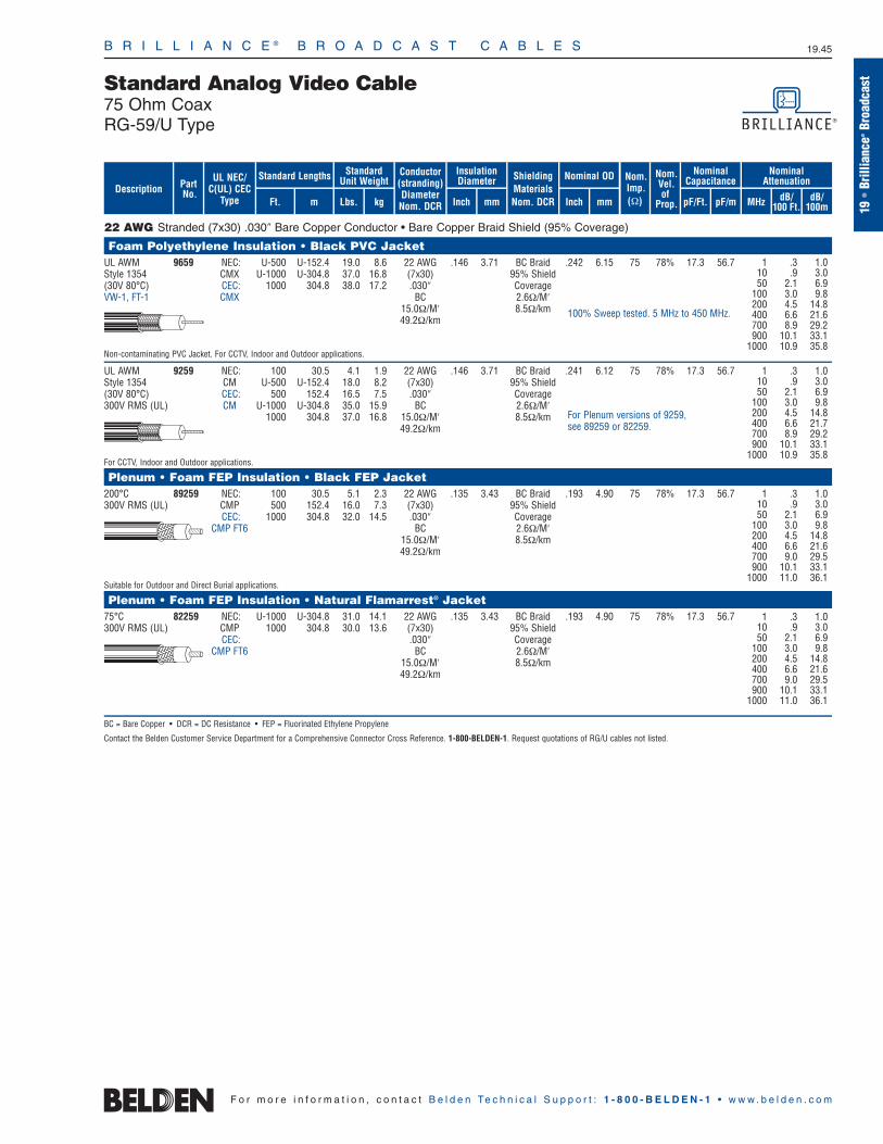
B R I L L I A N C E ® B R O A D C A S T C A B L E S 19.45
19•
Brill
ianc
e®Br
oadc
astStandard Analog Video Cable
75 Ohm CoaxRG-59/U Type
F o r m o r e i n f o r m a t i o n , c o n t a c t B e l d e n Te c h n i c a l S u p p o r t : 1 - 8 0 0 - B E L D E N - 1 • w w w . b e l d e n . c o m
22 AWG Stranded (7x30) .030″ Bare Copper Conductor • Bare Copper Braid Shield (95% Coverage)
Foam Polyethylene Insulation • Black PVC JacketUL AWM 9659 NEC: U-500 U-152.4 19.0 8.6 22 AWG .146 3.71 BC Braid .242 6.15 75 78% 17.3 56.7Style 1354 CMX U-1000 U-304.8 37.0 16.8 (7x30) 95% Shield(30V 80°C) CEC: 1000 304.8 38.0 17.2 .030″ CoverageVW-1, FT-1 CMX BC 2.6Ω/M′
15.0Ω/M′ 8.5Ω/km49.2Ω/km
Non-contaminating PVC Jacket. For CCTV, Indoor and Outdoor applications.
UL AWM 9259 NEC: 100 30.5 4.1 1.9 22 AWG .146 3.71 BC Braid .241 6.12 75 78% 17.3 56.7Style 1354 CM U-500 U-152.4 18.0 8.2 (7x30) 95% Shield(30V 80°C) CEC: 500 152.4 16.5 7.5 .030″ Coverage300V RMS (UL) CM U-1000 U-304.8 35.0 15.9 BC 2.6Ω/M′
1000 304.8 37.0 16.8 15.0Ω/M′ 8.5Ω/km49.2Ω/km
For CCTV, Indoor and Outdoor applications.
Plenum • Foam FEP Insulation • Black FEP Jacket200°C 89259 NEC: 100 30.5 5.1 2.3 22 AWG .135 3.43 BC Braid .193 4.90 75 78% 17.3 56.7300V RMS (UL) CMP 500 152.4 16.0 7.3 (7x30) 95% Shield
CEC: 1000 304.8 32.0 14.5 .030″ CoverageCMP FT6 BC 2.6Ω/M′
15.0Ω/M′ 8.5Ω/km49.2Ω/km
Suitable for Outdoor and Direct Burial applications.
Plenum • Foam FEP Insulation • Natural Flamarrest® Jacket75°C 82259 NEC: U-1000 U-304.8 31.0 14.1 22 AWG .135 3.43 BC Braid .193 4.90 75 78% 17.3 56.7300V RMS (UL) CMP 1000 304.8 30.0 13.6 (7x30) 95% Shield
CEC: .030″ CoverageCMP FT6 BC 2.6Ω/M′
15.0Ω/M′ 8.5Ω/km49.2Ω/km
BC = Bare Copper • DCR = DC Resistance • FEP = Fluorinated Ethylene Propylene
Contact the Belden Customer Service Department for a Comprehensive Connector Cross Reference. 1-800-BELDEN-1. Request quotations of RG/U cables not listed.
1 .3 1.010 .9 3.050 2.1 6.9
100 3.0 9.8200 4.5 14.8400 6.6 21.6700 8.9 29.2900 10.1 33.1
1000 10.9 35.8
1 .3 1.010 .9 3.050 2.1 6.9
100 3.0 9.8200 4.5 14.8400 6.6 21.7700 8.9 29.2900 10.1 33.1
1000 10.9 35.8
For Plenum versions of 9259, see 89259 or 82259.
1 .3 1.010 .9 3.050 2.1 6.9
100 3.0 9.8200 4.5 14.8400 6.6 21.6700 9.0 29.5900 10.1 33.1
1000 11.0 36.1
1 .3 1.010 .9 3.050 2.1 6.9
100 3.0 9.8200 4.5 14.8400 6.6 21.6700 9.0 29.5900 10.1 33.1
1000 11.0 36.1
100% Sweep tested. 5 MHz to 450 MHz.
ShieldingMaterialsNom. DCR
Nom.Imp.(Ω)
Insulation Diameter Nominal OD
Inch mm Inch mm
Conductor(stranding)DiameterNom. DCR
StandardUnit WeightStandard Lengths
Lbs. kgFt. m
UL NEC/C(UL) CEC
Type
PartNo.
MHz dB/100 Ft.
dB/100m
Nominal Attenuation
Nominal Capacitance
pF/mpF/Ft.
Nom.Vel.of
Prop.Description

B R I L L I A N C E ® B R O A D C A S T C A B L E S 19.46
F o r m o r e i n f o r m a t i o n , c o n t a c t B e l d e n Te c h n i c a l S u p p o r t : 1 - 8 0 0 - B E L D E N - 1 • w w w . b e l d e n . c o m
20 AWG Solid .032″ Bare Copper-covered Steel Conductor • Bare Copper Braid Shield (80% Coverage)
Foam Polyethylene Insulation • Black PVC Jacket75°C 9240 — 1000† 304.8 31.0 14.1 20 AWG .143 3.63 BC Braid .241 6.12 75 78% 17.3 56.7
(solid) 80% Shield.032″ CoverageBCCS 5.6Ω/M′
44.5Ω/M′ 18.4Ω/km146.0Ω/km
20 AWG Solid .032″ Bare Copper-covered Steel Conductor • Bare Copper Braid Shield (95% Coverage)
Foam Polyethylene Insulation • Black Polyethylene Jacket80°C 8212 — U-500 U-152.4 16.5 7.5 20 AWG .143 3.63 BC Braid .242 6.15 75 78% 17.3 56.7
500 152.4 15.0 6.8 (solid) 95% ShieldU-1000 U-304.8 31.0 14.1 .032″ Coverage
1000 304.8 33.0 15.0 BCCS 2.6Ω/M′44.5Ω/M′ 8.5Ω/km
146.0Ω/km
Foam Polyethylene Insulation • Black PVC Jacket80°C 9274 NEC: 500 152.4 15.5 7.0 20 AWG .143 3.63 BC Braid .240 6.10 75 82% 16.3 53.5
CM 1000 304.8 35.0 15.9 (solid) 95% ShieldCEC: .032″ CoverageCM BCCS 3.5Ω/M′
44.5Ω/M′ 11.5Ω/km146.0Ω/km
20 AWG Solid .032″ Bare Copper Conductor • Bare Copper Braid Shield (95% Coverage)
Gas-injected Foam HDPE Insulation • Black PVC JacketUL AWM 1426A NEC: U-1000 U-304.8 35.0 15.9 20 AWG .145 3.68 BC Braid .242 6.15 75 83% 16.3 53.5Style 1354 CM (solid) 95% Shield(30V 75°C) .032″ Coverage60°C (UL) BC 2.6Ω/M′
10.0Ω/M′ 8.5Ω/km32.8Ω/km
Series 59 • 20 AWG Solid .032″ Bare Copper-covered Steel Conductor • Duofoil® or Duobond® + Aluminum Braid Shield (40% Coverage)
Gas-injected Foam Polyethylene Insulation • Black PVC Jacket80°C 9275 NEC: U-500 U-152.4 12.0 5.5 20 AWG .144 3.66 Duofoil .237 6.02 75 83% 16.2 53.1
CATV CM U-1000 U-304.8 23.0 10.4 (solid) + 40% CEC: 1000 304.8 24.0 10.9 .032″ AluminumCM BCCS Braid
44.5Ω/M′ 17.0Ω/M′146.0Ω/km 55.8Ω/km
U-1000 ft. put-up also available in White.
80°C 9100 NEC: U-500 U-152.4 12.0 5.5 20 AWG .144 3.66 Duobond II .237 6.02 75 83% 16.2 53.1CATV CM U-1000 U-304.8 23.0 10.4 (solid) + 40%
CEC: 1000 304.8 24.0 10.9 .032″ AluminumCM BCCS Braid
44.5Ω/M′ 17.0Ω/M′146.0Ω/km 55.8Ω/km
U-1000 ft. put-up also available in White.
BC = Bare Copper • BCCS = Bare Copper-covered Steel • DCR = DC Resistance
Contact the Belden Customer Service Department for a Comprehensive Connector Cross Reference. 1-800-BELDEN-1. Request quotations of RG/U cables not listed.†Spools and/or UnReel® cartons are one piece, but length may vary ±5% from length shown.
1 .6 2.010 1.0 3.350 2.1 6.9
100 3.0 9.8200 4.5 14.8400 6.6 21.6700 8.9 29.2900 10.1 33.1
1000 10.9 35.8
1 .6 2.010 1.0 3.350 2.1 6.9
100 3.0 9.8200 4.5 14.8400 6.6 21.6700 8.9 29.2900 10.1 33.1
1000 10.9 35.8
1 .6 2.010 1.0 3.350 2.1 6.9
100 3.0 9.8200 4.5 14.8400 6.6 21.6700 8.9 29.2900 10.1 33.1
1000 10.9 35.8
1 .3 1.010 .9 3.050 1.9 6.2
100 2.6 8.5200 3.6 11.8400 5.0 16.4700 7.0 23.0900 8.0 26.3
1000 8.5 27.9
100% Sweep tested. 5 MHz to 850 MHz.
100% Sweep tested. 5 MHz to 450 MHz.
100% Sweep tested. 5 MHz to 450 MHz.
ShieldingMaterialsNom. DCR
Nom.Imp.(Ω)
Nominal Core OD Nominal OD
Inch mm Inch mm
Conductor(stranding)DiameterNom. DCR
StandardUnit WeightStandard Lengths
Lbs. kgFt. m
UL NEC/C(UL) CEC
Type
PartNo.
MHz dB/100 Ft.
dB/100m
Nominal Attenuation
Nominal Capacitance
pF/mpF/Ft.
Nom.Vel.of
Prop.Description
See Chart on page 6.88
See Chart on page 6.88
100% Sweep tested. 5 MHz to 550 MHz.
100% Sweep tested. 5 MHz to 1 GHz.
Standard Analog Video Cable75 Ohm CoaxRG-59/U Type

B R I L L I A N C E ® B R O A D C A S T C A B L E S 19.47
19•
Brill
ianc
e®Br
oadc
astStandard Analog Video Cable
75 Ohm CoaxRG-6/U Type
F o r m o r e i n f o r m a t i o n , c o n t a c t B e l d e n Te c h n i c a l S u p p o r t : 1 - 8 0 0 - B E L D E N - 1 • w w w . b e l d e n . c o m
21 AWG Solid .028″ Bare Copper-covered Steel Conductor • Bare Copper Double Braid Shields (98% Coverage)
Polyethylene Insulation • Black Polyethylene JacketMATV Cable 8215 — 1000 304.8 74.0 33.6 21 AWG .185 4.70 (2) BC .332 8.43 75 66% 20.5 67.280°C (solid) Braids
.028″ 98% ShieldBCCS Coverage
32.0Ω/M′ 1.1Ω/M′105.0Ω/km 3.6Ω/km
18 AWG Solid .037″ Bare Copper Conductor • Bare Copper Double Braid Shields (98% Coverage)
Foam Polyethylene Insulation • Black PVC Jacket80°C 9290 NEC: 1000 304.8 59.0 26.8 18 AWG .180 4.57 (2) BC .288 7.32 75 81% 17.3 56.7
CM 2000 609.6 118.0 53.5 (solid) BraidsCEC: .037″ 98% ShieldCM BC Coverage
7.5Ω/M′ 2.0Ω/M′24.6Ω/km 6.6Ω/km
Suitable for Indoor and Outdoor applications.
18 AWG Solid .040″ Bare Copper Conductor • Duofoil® (100% Coverage) + Tinned Copper Braid Shield (60% Coverage)
Gas-injected Foam HDPE Insulation • Black PVC JacketUL AWM 9248 NEC: U-500 U-152.4 16.5 7.5 18 AWG .180 4.57 Duofoil .270 6.86 75 82% 16.2 53.1Style 1354 CM 500 152.4 15.0 6.8 (solid) + 60% TC(30V 80°C) CEC: U-1000 U-304.8 32.0 14.5 .040″ Braid
CM 1000 304.8 33.0 15.0 BC 5.6Ω/M′1640 500.0 55.8 25.3 6.4Ω/M′ 18.4Ω/km3280 1000.0 108.2 49.2 21.0Ω/km
18 AWG Solid .040″ Bare Copper Conductor • Duofoil® (100% Coverage) + Tinned Copper Braid Shield (65% Coverage)
Plenum • Foam FEP Insulation • Black FEP Jacket200°C 89248 NEC: 500 152.4 15.0 6.8 18 AWG .170 4.32 Duofoil .222 5.64 75 82% 16.5 54.1
CMP 1000 304.8 33.0 15.0 (solid) + 65% TCCEC: 2000 609.6 64.0 29.0 .040″ Braid
CMP FT6 BC 5.1Ω/M′6.4Ω/M′ 16.7Ω/km
21.0Ω/km
Suitable for Outdoor and Direct Burial applications.
Plenum • Foam FEP Insulation • Natural Flamarrest® Jacket75°C 82248 NEC: U-1000 U-304.8 29.0 13.2 18 AWG .170 4.32 Duofoil .222 5.64 75 82% 16.5 54.1
CMP 1000 304.8 31.0 14.1 (solid) + 65% TCCEC: .040″ Braid
CMP FT6 BC 5.1Ω/M′6.4Ω/M′ 16.7Ω/km
21.0Ω/km
BC = Bare Copper • BCCS = Bare Copper-covered Steel • DCR = DC Resistance • FEP = Fluorinated Ethylene Propylene • HDPE = High-density Polyethylene • TC = Tinned Copper
Contact the Belden Customer Service Department for a Comprehensive Connector Cross Reference. 1-800-BELDEN-1. Request quotations of RG/U cables not listed.
1 .4 1.310 .8 2.650 1.9 6.2
100 2.7 8.9200 4.1 13.4400 5.9 19.4700 8.1 26.6900 9.4 30.8
1000 9.8 32.1
1 .2 .710 .7 2.350 1.7 5.6
100 2.5 8.2200 3.6 11.8400 5.0 16.4700 7.2 23.6900 8.3 27.2
1000 8.8 28.9
1 .3 1.010 .7 2.350 1.5 4.9
100 2.0 6.6200 2.8 9.2400 4.0 13.1700 5.3 17.4900 6.1 20.0
1000 6.5 21.3
1 .3 1.010 .7 2.350 1.6 5.2
100 2.2 7.2200 3.0 9.8400 4.6 15.1700 6.6 21.6900 7.7 25.3
1000 8.2 26.9
1 .3 1.010 .7 2.350 1.5 4.9
100 2.1 6.9200 3.1 10.2400 4.5 14.8700 6.0 19.7900 6.9 22.6
1000 7.3 23.9
For Plenum versions of 9248, see 89248 or 82248.
100% Sweep tested. 5 MHz to 450 MHz.
100% Sweep tested. 5 MHz to 450 MHz.
100% Sweep tested. 5 MHz to 450 MHz.
100% Sweep tested. 5 MHz to 450 MHz.
100% Sweep tested. 5 MHz to 450 MHz.
ShieldingMaterialsNom. DCR
Nom.Imp.(Ω)
Nominal Core OD Nominal OD
Inch mm Inch mm
Conductor(stranding)DiameterNom. DCR
StandardUnit WeightStandard Lengths
Lbs. kgFt. m
UL NEC/C(UL) CEC
Type
PartNo.
MHz dB/100 Ft.
dB/100m
Nominal Attenuation
Nominal Capacitance
pF/mpF/Ft.
Nom.Vel.of
Prop.Description
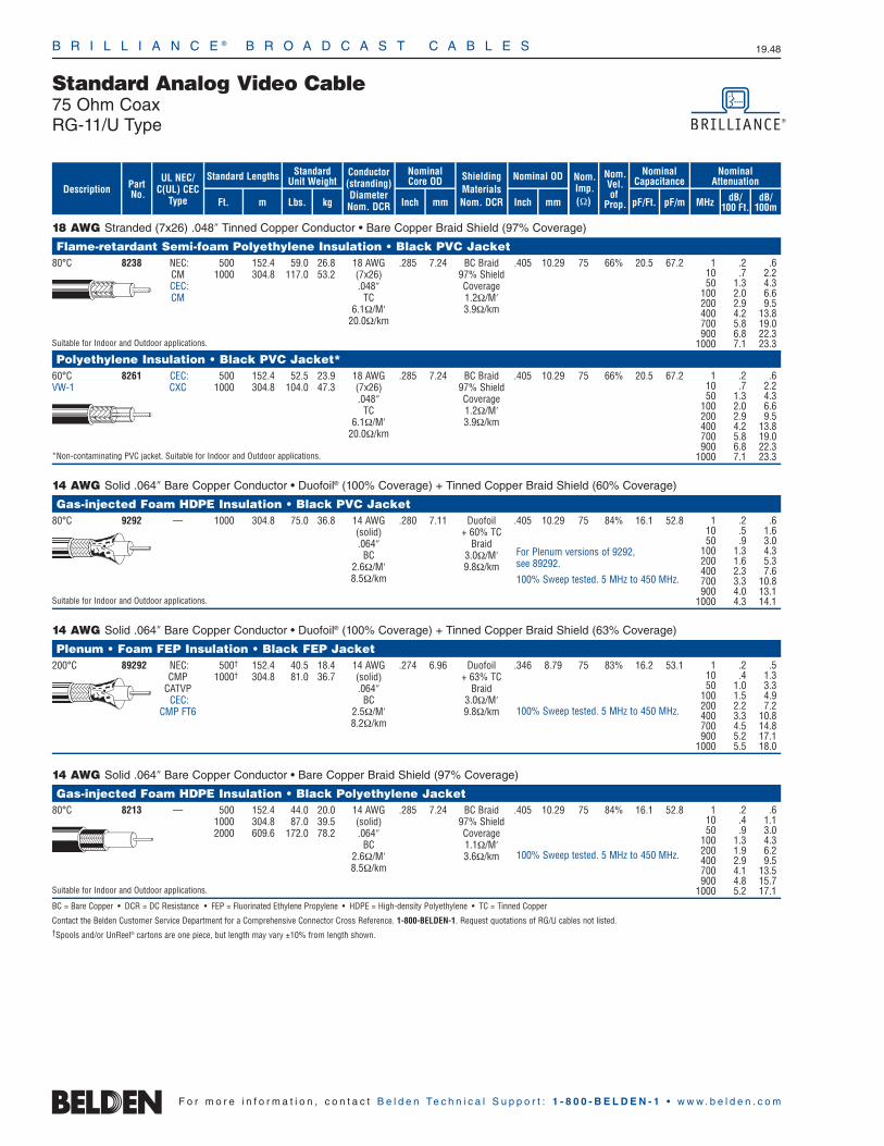
B R I L L I A N C E ® B R O A D C A S T C A B L E S 19.48
F o r m o r e i n f o r m a t i o n , c o n t a c t B e l d e n Te c h n i c a l S u p p o r t : 1 - 8 0 0 - B E L D E N - 1 • w w w . b e l d e n . c o m
18 AWG Stranded (7x26) .048″ Tinned Copper Conductor • Bare Copper Braid Shield (97% Coverage)
Flame-retardant Semi-foam Polyethylene Insulation • Black PVC Jacket80°C 8238 NEC: 500 152.4 59.0 26.8 18 AWG .285 7.24 BC Braid .405 10.29 75 66% 20.5 67.2
CM 1000 304.8 117.0 53.2 (7x26) 97% ShieldCEC: .048″ CoverageCM TC 1.2Ω/M′
6.1Ω/M′ 3.9Ω/km20.0Ω/km
Suitable for Indoor and Outdoor applications.
Polyethylene Insulation • Black PVC Jacket*60°C 8261 CEC: 500 152.4 52.5 23.9 18 AWG .285 7.24 BC Braid .405 10.29 75 66% 20.5 67.2VW-1 CXC 1000 304.8 104.0 47.3 (7x26) 97% Shield
.048″ CoverageTC 1.2Ω/M′
6.1Ω/M′ 3.9Ω/km20.0Ω/km
*Non-contaminating PVC jacket. Suitable for Indoor and Outdoor applications.
14 AWG Solid .064″ Bare Copper Conductor • Duofoil® (100% Coverage) + Tinned Copper Braid Shield (60% Coverage)
Gas-injected Foam HDPE Insulation • Black PVC Jacket80°C 9292 — 1000 304.8 75.0 36.8 14 AWG .280 7.11 Duofoil .405 10.29 75 84% 16.1 52.8
(solid) + 60% TC.064″ Braid
BC 3.0Ω/M′2.6Ω/M′ 9.8Ω/km8.5Ω/km
Suitable for Indoor and Outdoor applications.
14 AWG Solid .064″ Bare Copper Conductor • Duofoil® (100% Coverage) + Tinned Copper Braid Shield (63% Coverage)
Plenum • Foam FEP Insulation • Black FEP Jacket200°C 89292 NEC: 500† 152.4 40.5 18.4 14 AWG .274 6.96 Duofoil .346 8.79 75 83% 16.2 53.1
CMP 1000† 304.8 81.0 36.7 (solid) + 63% TCCATVP .064″ Braid
CEC: BC 3.0Ω/M′CMP FT6 2.5Ω/M′ 9.8Ω/km
8.2Ω/km
14 AWG Solid .064″ Bare Copper Conductor • Bare Copper Braid Shield (97% Coverage)
Gas-injected Foam HDPE Insulation • Black Polyethylene Jacket80°C 8213 — 500 152.4 44.0 20.0 14 AWG .285 7.24 BC Braid .405 10.29 75 84% 16.1 52.8
1000 304.8 87.0 39.5 (solid) 97% Shield2000 609.6 172.0 78.2 .064″ Coverage
BC 1.1Ω/M′2.6Ω/M′ 3.6Ω/km8.5Ω/km
Suitable for Indoor and Outdoor applications.
BC = Bare Copper • DCR = DC Resistance • FEP = Fluorinated Ethylene Propylene • HDPE = High-density Polyethylene • TC = Tinned Copper
Contact the Belden Customer Service Department for a Comprehensive Connector Cross Reference. 1-800-BELDEN-1. Request quotations of RG/U cables not listed.†Spools and/or UnReel® cartons are one piece, but length may vary ±10% from length shown.
1 .2 .610 .7 2.250 1.3 4.3
100 2.0 6.6200 2.9 9.5400 4.2 13.8700 5.8 19.0900 6.8 22.3
1000 7.1 23.3
1 .2 .610 .7 2.250 1.3 4.3
100 2.0 6.6200 2.9 9.5400 4.2 13.8700 5.8 19.0900 6.8 22.3
1000 7.1 23.3
1 .2 .610 .4 1.150 .9 3.0
100 1.3 4.3200 1.9 6.2400 2.9 9.5700 4.1 13.5900 4.8 15.7
1000 5.2 17.1
1 .2 .610 .5 1.650 .9 3.0
100 1.3 4.3200 1.6 5.3400 2.3 7.6700 3.3 10.8900 4.0 13.1
1000 4.3 14.1
1 .2 .510 .4 1.350 1.0 3.3
100 1.5 4.9200 2.2 7.2400 3.3 10.8700 4.5 14.8900 5.2 17.1
1000 5.5 18.0
For Plenum versions of 9292, see 89292.
100% Sweep tested. 5 MHz to 450 MHz.
100% Sweep tested. 5 MHz to 450 MHz.
100% Sweep tested. 5 MHz to 450 MHz.
ShieldingMaterialsNom. DCR
Nom.Imp.(Ω)
Nominal Core OD Nominal OD
Inch mm Inch mm
Conductor(stranding)DiameterNom. DCR
StandardUnit WeightStandard Lengths
Lbs. kgFt. m
UL NEC/C(UL) CEC
Type
PartNo.
MHz dB/100 Ft.
dB/100m
Nominal Attenuation
Nominal Capacitance
pF/mpF/Ft.
Nom.Vel.of
Prop.Description
Standard Analog Video Cable75 Ohm CoaxRG-11/U Type
B R I L L I A N C E ® B R O A D C A S T C A B L E S 19.49
19•
Brill
ianc
e®Br
oadc
ast
F o r m o r e i n f o r m a t i o n , c o n t a c t B e l d e n Te c h n i c a l S u p p o r t : 1 - 8 0 0 - B E L D E N - 1 • w w w . b e l d e n . c o m
Precision Video Cable for Analog and DigitalOverview
Analog Video
Belden® precision video cables are used in critical analog and digitalvideo circuits and high quality applications such as live broadcast innetwork studios and pre- or post-production facilities. They shouldbe used where superior signal integrity is required.
Precision video cables usually have solid center conductors anddual shields. The dielectrics can either be foamed or solid. Tighterimpedance and attenuation tolerances, superior Return Loss (RL)specifications, and improved shielding give precision video cablestheir no-compromise performance.
The frequency response loss curves of the solid dielectric cables,such as 8281, are different from those with foam dielectric, like1505A. Therefore, different equalization equipment is necessaryand commercially available. Avoid mixing 8281 and 1505A for this reason.
Digital Video
Precision video cables are also recommended for the latest digitalvideo applications. Since its inception in the early ‘80s, digitalbroadcast is quickly becoming the preferred video format. Theadvantages of the digital format are many. Digital is very stable, minimizing equipment adjustments. Copies or reproductions retainthe quality of the original. Signal degradation is virtually eliminated,and noise immunity is greatly improved. Digital video is transmittedover a cable in either a Parallel or Serial format.
Parallel Digital Video (D1, D2 & D3)
The Parallel format transmits each bit of an 8 or 10 bit digital wordsimultaneously or parallel down a separate signal path at a frequencyof 27 Mb/s. This type of transmission requires the use of a 100 to120 ohm 12-1/2 pair data cable (Belden part nos. 8142 or 8112page 19.56). These cables are limited to a transmission distance ofless than 30 meters.
Serial Digital Video (SDI)
The Society of Motion Picture and Television Engineers (SMPTE)has developed two different standards for serial digital transmissions(SDI). A third format that transmits at 540 Mb/s is under development.There is also a European standards body known as ITU (formerlyCCIR) that developed the specifications for Europe known as PAL.Each of these specifications differs in frequency and transmissiontechnology, i.e., composite or component.
SMPTE 259M — Covers digital video transmissions of composite NTSC 143 Mb/s (Level A) and PAL 177 Mb/s (Level B). It also covers 525/625 component transmissions of 270 Mb/s (Level C) and 360 Mb/s (Level D).
SMPTE 292M — Covers the newest format for HDTV transmissions at 1.458 Gb/s.
SMPTE 344M — Covers component widescreen transmissions of 540 Mb/s.
ITU-R BT.601 — International standard covers component PAL transmissions of 177 Mb/s.
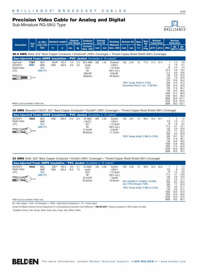
B R I L L I A N C E ® B R O A D C A S T C A B L E S 19.50
F o r m o r e i n f o r m a t i o n , c o n t a c t B e l d e n Te c h n i c a l S u p p o r t : 1 - 8 0 0 - B E L D E N - 1 • w w w . b e l d e n . c o m
28.5 AWG Solid .012″ Bare Copper Conductor • Duobond® (100% Coverage) + Tinned Copper Braid Shield (95% Coverage)
Gas-injected Foam HDPE Insulation • PVC Jacket (Available in 10 colors)*DigiTruck® 179DT NEC: 500 152.4 5.0 2.3 28.5 AWG .056 1.42 Duobond .100 2.54 75 77% 17.4 57.4SDI/HDTV u CMR 1000 304.8 8.0 3.6 (solid) (100%)Digital Video CEC: .012″ + TC Braid75°C CMG FT4 BC (95% Cov.)
108Ω/M′ 8.9Ω/M′350Ω/km 29.2Ω/km
500 ft. put-up available in Black only.
25 AWG Stranded (19x37) .021″ Bare Copper Conductor • Duofoil® (100% Coverage) + Tinned Copper Braid Shield (95% Coverage)
Gas-injected Foam HDPE Insulation • PVC Jacket (Available in 10 colors)*SDI/HDTV 1865A NEC: 1000 304.8 14.0 6.4 25 AWG .094 2.39 Duofoil .150 3.81 75 82% 16.5 54.1Digital Video CMR (19x37) (100%)75°C CEC: .021″ + TC Braid
CMG FT4 BC (95% Cov.)27.4Ω/M′ 5.4Ω/M′89.9Ω/km 17.7Ω/km
23 AWG Solid .023″ Bare Copper Conductor • Duofoil (100% Coverage) + Tinned Copper Braid Shield (95% Coverage)
Gas-injected Foam HDPE Insulation • PVC Jacket (Available in 10 colors)*SDI/HDTV 1855A NEC: 500 152.4 9.0 4.1 23 AWG .102 2.59 Duofoil .159 4.03 75 82% 16.3 53.5Digital Video CMR 1000 304.8 16.0 7.3 (solid) (100%)75°C CEC: .023″ + TC Braid
CMG FT4 BC (95% Cov.)20.1Ω/M′ 7.6Ω/M′65.9Ω/km 24.9Ω/km
500 ft. put-up available in Black only.
BC = Bare Copper • DCR = DC Resistance • HDPE = High-density Polyethylene • TC = Tinned Copper
Contact the Belden Customer Service Department for a Comprehensive Connector Cross Reference. 1-800-BELDEN-1. Request quotations of RG/U cables not listed.
*Available in Brown, Red, Orange, Yellow, Green, Blue, Purple, Gray, White or Black.
1 .5 1.53.6 1.0 3.110 1.6 5.2
71.5 3.7 12.1135 5.0 16.4270 7.1 23.3360 8.2 26.9540 10.1 33.1720 11.8 38.7750 12.0 39.4
1000 13.9 45.61500 17.0 55.82250 20.8 68.23000 24.0 78.7
1 .4 1.33.6 .8 2.610 1.2 3.9
71.5 3.1 10.0135 3.8 12.5270 5.4 17.7360 6.2 20.3540 7.7 25.3720 9.5 31.1750 9.6 31.5
1000 10.5 34.41500 13.0 42.62250 16.0 52.53000 18.5 60.7
Also available in multiples, bundled. See 7787A through 7792A.
100% Sweep tested. 5 MHz to 3 GHz.
100% Sweep tested. 5 MHz to 3 GHz.
ShieldingMaterialsNom. DCR
Nom.Imp.(Ω)
Nominal Core OD Nominal OD
Inch mm Inch mm
Conductor(stranding)DiameterNom. DCR
StandardUnit WeightStandard Lengths
Lbs. kgFt. m
UL NEC/C(UL) CEC
Type
PartNo.
MHz dB/100 Ft.
dB/100m
Nominal Attenuation
Nominal Capacitance
pF/mpF/Ft.
Nom.Vel.of
Prop.Description
100% Sweep Tested to 3 GHz.Guaranteed Return Loss: -21dB Min.
1 1.2 3.9 5 1.9 6.1
10 2.4 7.8 67.5 5.9 19.3 71.5 6.0 19.6 100 6.9 22.6 135 7.9 25.8 270 10.8 35.4 360 12.5 41.0 540 15.4 50.5 720 17.9 58.7 750 18.3 60.0
1000 21.3 69.9 1500 26.3 86.3 2000 30.8 101.1 2250 32.8 107.63000 38.3 125.7
Precision Video Cable for Analog and DigitalSub-Miniature RG-59/U Type
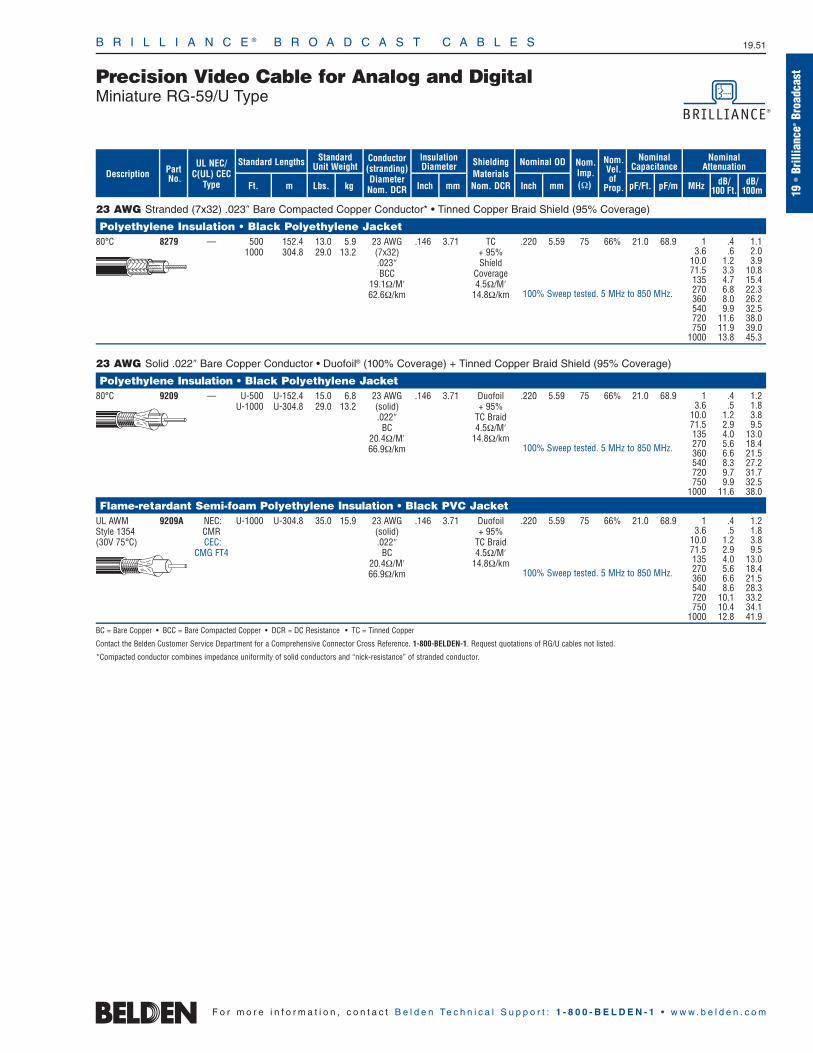
Precision Video Cable for Analog and DigitalMiniature RG-59/U Type
B R I L L I A N C E ® B R O A D C A S T C A B L E S 19.51
19•
Brill
ianc
e®Br
oadc
ast
F o r m o r e i n f o r m a t i o n , c o n t a c t B e l d e n Te c h n i c a l S u p p o r t : 1 - 8 0 0 - B E L D E N - 1 • w w w . b e l d e n . c o m
23 AWG Stranded (7x32) .023″ Bare Compacted Copper Conductor* • Tinned Copper Braid Shield (95% Coverage)
Polyethylene Insulation • Black Polyethylene Jacket80°C 8279 — 500 152.4 13.0 5.9 23 AWG .146 3.71 TC .220 5.59 75 66% 21.0 68.9
1000 304.8 29.0 13.2 (7x32) + 95% .023″ ShieldBCC Coverage
19.1Ω/M′ 4.5Ω/M′62.6Ω/km 14.8Ω/km
23 AWG Solid .022″ Bare Copper Conductor • Duofoil® (100% Coverage) + Tinned Copper Braid Shield (95% Coverage)
Polyethylene Insulation • Black Polyethylene Jacket80°C 9209 — U-500 U-152.4 15.0 6.8 23 AWG .146 3.71 Duofoil .220 5.59 75 66% 21.0 68.9
U-1000 U-304.8 29.0 13.2 (solid) + 95%.022″ TC Braid
BC 4.5Ω/M′20.4Ω/M′ 14.8Ω/km66.9Ω/km
Flame-retardant Semi-foam Polyethylene Insulation • Black PVC JacketUL AWM 9209A NEC: U-1000 U-304.8 35.0 15.9 23 AWG .146 3.71 Duofoil .220 5.59 75 66% 21.0 68.9Style 1354 CMR (solid) + 95%(30V 75°C) CEC: .022″ TC Braid
CMG FT4 BC 4.5Ω/M′20.4Ω/M′ 14.8Ω/km66.9Ω/km
BC = Bare Copper • BCC = Bare Compacted Copper • DCR = DC Resistance • TC = Tinned Copper
Contact the Belden Customer Service Department for a Comprehensive Connector Cross Reference. 1-800-BELDEN-1. Request quotations of RG/U cables not listed.
*Compacted conductor combines impedance uniformity of solid conductors and “nick-resistance” of stranded conductor.
1 .4 1.13.6 .6 2.0
10.0 1.2 3.971.5 3.3 10.8135 4.7 15.4270 6.8 22.3360 8.0 26.2540 9.9 32.5720 11.6 38.0750 11.9 39.0
1000 13.8 45.3
1 .4 1.23.6 .5 1.8
10.0 1.2 3.871.5 2.9 9.5135 4.0 13.0270 5.6 18.4360 6.6 21.5540 8.3 27.2720 9.7 31.7750 9.9 32.5
1000 11.6 38.0
1 .4 1.23.6 .5 1.8
10.0 1.2 3.871.5 2.9 9.5135 4.0 13.0270 5.6 18.4360 6.6 21.5540 8.6 28.3720 10.1 33.2750 10.4 34.1
1000 12.8 41.9
100% Sweep tested. 5 MHz to 850 MHz.
100% Sweep tested. 5 MHz to 850 MHz.
100% Sweep tested. 5 MHz to 850 MHz.
ShieldingMaterialsNom. DCR
Nom.Imp.(Ω)
Insulation Diameter Nominal OD
Inch mm Inch mm
Conductor(stranding)DiameterNom. DCR
StandardUnit WeightStandard Lengths
Lbs. kgFt. m
UL NEC/C(UL) CEC
Type
PartNo.
MHz dB/100 Ft.
dB/100m
Nominal Attenuation
Nominal Capacitance
pF/mpF/Ft.
Nom.Vel.of
Prop.Description
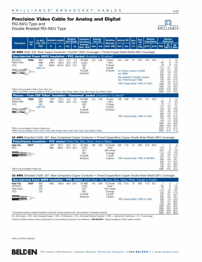
B R I L L I A N C E ® B R O A D C A S T C A B L E S 19.52
F o r m o r e i n f o r m a t i o n , c o n t a c t B e l d e n Te c h n i c a l S u p p o r t : 1 - 8 0 0 - B E L D E N - 1 • w w w . b e l d e n . c o m
20 AWG Solid .032″ Bare Copper Conductor • Duofoil® (100% Coverage) + Tinned Copper Braid Shield (95% Coverage)
Gas-injected Foam HDPE Insulation • PVC Jacket (Available in 10 colors)
SDI/HDTV 1505A NEC: 500 152.4 15.5 7.0 20 AWG .145 3.68 Duofoil .233 5.92 75 83% 16.3 53.5Digital Video CMR 1000 304.8 35.0 15.9 (solid) + 95%75°C CEC: 5000 1524.0 165.0 74.8 .032″ TC Braid
CMG FT4 BC 3.8Ω/M′10.0Ω/M′ 12.5Ω/km32.8Ω/km
500 ft. put-up available in Black, Red or Blue only.1000 ft. and 5000 ft. put-ups available in all ten colors: Brown, Red, Orange, Yellow, Green, Blue, Purple, Gray, White or Black.
Plenum • Foam FEP Teflon® Insulation • Flamarrest® Jacket (Available in 10 colors)
SDI/HDTV 1506A NEC: 500 152.4 14.5 6.6 20 AWG .133 3.38 Duofoil .196 4.98 75 84% 16.1 52.8Digital Video CMP 1000 304.8 29.0 13.2 (solid) + 95%75°C CEC: .032″ TC Braid
CMP FT6 BC 3.2Ω/M′10.0Ω/M′ 10.5Ω/km32.8Ω/km
500 ft. put-up available in Black or Natural only.1000 ft. put-up available in all ten colors: Brown, Red, Orange, Yellow, Green, Blue, Purple, Gray, Natural or Black.
22 AWG Stranded (7x29) .031″ Bare Compacted Copper Conductor* • Tinned Copper/Bare Copper Double Braid Shield (98% Coverage)
Polyethylene Insulation • PVC Jacket (Matte Red, Blue, Green, Gray or Black)High-Flex 8281F — 500 152.4 34.5 15.7 22 AWG .198 4.90 TC Double .305 7.75 75 66% 21.0 68.960°C 1000 304.8 67.0 30.4 (7x29) Braid
.031″ 98% ShieldBCC Coverage
12.2Ω/M′ 1.7Ω/M′40.0Ω/km 5.6Ω/km
500 ft. put-up available in Black only.
22 AWG Stranded (7x29) .031″ Bare Compacted Copper Conductor* • Tinned Copper/Bare Copper Double Braid Shield (95% Coverage)
Gas-injected Foam HDPE Insulation • PVC Jacket (Matte Black, Red, Green, Blue, Yellow, White, Orange or Purple)High-Flex 1505F NEC: 1000 304.8 45.0 20.4 22 AWG .145 3.68 TC Double .242 6.15 75 80% 17.0 55.7SDI/HDTV CM (7x29) BraidVideo Patch CEC: .031″ 95% Shield75°C CM BCC Coverage
12.2Ω/M′ 2.4Ω/M′40.0Ω/km 7.8Ω/km
*Compacted conductor combines impedance uniformity of solid conductors and “nick-resistance” of stranded conductor.
BC = Bare Copper • BCC = Bare Compacted Copper • DCR = DC Resistance • FEP = Fluorinated Ethylene Propylene • HDPE = High-density Polyethylene • TC = Tinned Copper
Contact the Belden Customer Service Department for a Comprehensive Connector Cross Reference. 1-800-BELDEN-1. Request quotations of RG/U cables not listed.
1 .3 1.03.6 .6 1.810 .9 2.9
71.5 2.1 6.9135 2.7 8.9270 3.8 12.5360 4.4 14.4540 5.5 18.0720 6.4 21.0750 6.5 21.3
1000 7.6 24.91500 9.3 30.52250 11.6 38.03000 13.4 44.0
1 .3 1.03.6 .6 2.010 1.1 3.4
71.5 2.3 7.4135 3.2 10.5270 4.6 14.9360 5.3 17.2540 6.4 21.0720 7.3 23.9750 7.5 24.6
1000 9.4 30.81500 12.8 42.02250 17.5 57.43000 21.9 71.8
For Plenum version of 1505A, see 1506A.
Also available in bundled versions. See 7794A through 7798A.
100% Sweep tested. 5 MHz to 3 GHz.
100% Sweep tested. 5 MHz to 3 GHz.
ShieldingMaterialsNom. DCR
Nom.Imp.(Ω)
Nominal Core OD Nominal OD
Inch mm Inch mm
Conductor(stranding)DiameterNom. DCR
StandardUnit WeightStandard Lengths
Lbs. kgFt. m
UL NEC/C(UL) CEC
Type
PartNo.
MHz dB/100 Ft.
dB/100m
Nominal Attenuation
Nominal Capacitance
pF/mpF/Ft.
Nom.Vel.of
Prop.Description
1 .2 .73.6 .5 1.610 .9 2.9
71.5 2.5 8.2135 3.5 11.5270 5.1 16.7360 6.0 19.7540 7.4 24.3720 8.7 28.5750 8.9 29.2
1000 10.5 34.41500 13.3 43.62250 16.9 55.43000 20.3 66.6
100% Sweep tested. 5 MHz to 3 GHz.
Precision Video Cable for Analog and DigitalRG-59/U Type and Double Braided RG-59/U Type
1 .3 .93.6 .5 1.7
10.0 .9 2.971.5 2.5 8.0135 3.6 11.6270 5.1 16.7360 6.0 19.7540 7.4 24.3720 8.7 28.5750 8.9 29.2
1000 10.5 34.4
100% Sweep tested. 5 MHz to 830 MHz.
Teflon is a DuPont trademark.

B R I L L I A N C E ® B R O A D C A S T C A B L E S 19.53
19•
Brill
ianc
e®Br
oadc
astPrecision Video Cable for Analog and Digital
Double Braided RG-59/U Type
F o r m o r e i n f o r m a t i o n , c o n t a c t B e l d e n Te c h n i c a l S u p p o r t : 1 - 8 0 0 - B E L D E N - 1 • w w w . b e l d e n . c o m
20 AWG Solid .031″ Bare Copper Conductor • Tinned Copper/Bare Copper Double Braid Shield (98% Coverage)
Polyethylene Insulation • Gray PVC Jacket †
60°C 9231 NEC: 500 152.4 39.0 17.7 20 AWG .198 5.03 TC Double .305 7.75 75 66% 21.0 68.9VW-1 CMH 1000 304.8 76.0 34.5 (solid) Braid
CEC: .031″ 98% ShieldCMH FT1 BC Coverage
9.9Ω/M′ 1.1Ω/M′32.5Ω/km 3.6Ω/km
†Non-contaminating PVC jacket
Polyethylene Insulation • Clear Polyethylene JacketIndoor Use 9141 — 1000 304.8 73.0 33.2 20 AWG .200 5.06 TC Double .305 7.75 75 66% 20.0 65.680°C (solid) Braid
.031″ 98% ShieldBC Coverage
9.9Ω/M′ 1.1Ω/M′32.5Ω/km 3.6Ω/km
20 AWG Solid .031″ Bare Copper Conductor • Tinned Copper/Bare Copper Double Braid Shield (98% Coverage)
Polyethylene Insulation • Polyethylene Jacket (Available in Red, Yellow, Green, Blue, White, Orange or Black)80°C 8281 — 500 152.4 37.5 17.0 20 AWG .198 5.03 TC Double .305 7.75 75 66% 21.0 68.9
1000 304.8 74.0 33.6 (solid) Braid.031″ 98% Shield
BC Coverage9.9Ω/M′ 1.1Ω/M′
32.5Ω/km 3.6Ω/km
500 ft. put-up not available in White.
Flame-retardant Semi-Foam Polyethylene Insulation • PVC Jacket (Available in 9 colors)
UL AWM 8281B NEC: 1000 304.8 84.0 38.1 20 AWG .198 5.03 TC Double .305 7.75 75 66% 21.0 68.9Style 1354 CMR (solid) Braid(30V 80°C) CEC: .031″ 98% Shield
CMG FT4 BC Coverage9.9Ω/M′ 1.1Ω/M′
32.5Ω/km 3.6Ω/km
8281B available in Red, Orange, Yellow, Green, Blue, Purple, Gray, White or Black.
20 AWG Solid .031″ Bare Copper Conductor • Tinned Copper/Bare Copper Double Braid Shield (98% Coverage)
Plenum • FEP Insulation • Black Fluorocopolymer Jacket150°C 88281 NEC: 500 152.4 44.5 20.2 20 AWG .185 4.70 TC Double .271 6.88 75 70% 19.0 62.4
CMP 1000 304.8 86.0 39.1 (solid) BraidCEC: .031″ 98% Shield
CMP FT6 BC Coverage9.9Ω/M′ 1.1Ω/M′
32.5Ω/km 3.6Ω/km
Suitable for Outdoor and Direct Burial applications.
BC = Bare Copper • DCR = DC Resistance • FEP = Fluorinated Ethylene Propylene • TC = Tinned Copper
Contact the Belden Customer Service Department for a Comprehensive Connector Cross Reference. 1-800-BELDEN-1. Request quotations of RG/U cables not listed.
*Compacted conductor combines impedance uniformity of solid conductors and “nick-resistance” of stranded conductor.
1 .3 1.03.6 .5 1.6
10.0 .8 2.671.5 2.0 6.6135 3.5 11.5270 4.3 14.1360 5.0 16.4540 6.2 20.3720 7.2 23.6750 7.4 24.3
1000 9.1 29.8
1 .3 .83.6 .5 1.8
10.0 .8 2.671.5 2.1 6.9135 3.0 9.8270 4.3 14.1360 5.1 16.6540 6.3 20.7720 7.4 24.3750 7.6 24.9
1000 9.2 30.2
1 .3 .83.6 .5 1.8
10.0 .8 2.671.5 2.1 6.9135 3.0 9.8270 4.4 14.4360 5.1 16.6540 6.6 21.5720 7.8 25.4750 8.0 26.2
1000 10.2 33.5
1 .2 .73.6 .5 1.6
10.0 .8 2.671.5 2.3 7.5135 3.3 10.8270 5.1 16.7360 6.1 20.0540 8.0 26.2720 9.7 31.8750 10.0 32.8
1000 12.3 40.3
For Plenum version of 8281B, see 88281.
100% Sweep tested. 5 MHz to 850 MHz.
100% Sweep tested. 5 MHz to 850 MHz.
For Plenum version of 8281, see 88281.
100% Sweep tested. 5 MHz to 850 MHz.
100% Sweep tested. 5 MHz to 216 MHz.
ShieldingMaterialsNom. DCR
Nom.Imp.(Ω)
Nominal Core OD Nominal OD
Inch mm Inch mm
Conductor(stranding)DiameterNom. DCR
StandardUnit WeightStandard Lengths
Lbs. kgFt. m
UL NEC/C(UL) CEC
Type
PartNo.
MHz dB/100 Ft.
dB/100m
Nominal Attenuation
Nominal Capacitance
pF/mpF/Ft.
Nom.Vel.of
Prop.Description
1 .3 1.03.6 .5 1.6
10.0 .8 2.671.5 2.0 6.6135 3.5 11.5270 4.3 14.1360 5.0 16.4540 6.2 20.3720 7.2 23.6750 7.4 24.3
1000 9.1 29.8
100% Sweep tested. 5 MHz to 850 MHz.

RG-6/U Type • 18 AWG Solid .040″ Bare Copper Conductor • Duofoil® (100% Coverage) + Tinned Copper Braid Shield (95% Coverage)
Gas-injected Foam HDPE Insulation • PVC Jacket (Available in 10 colors)*SDI/HDTV 1694A NEC: 500 152.4 20.5 9.3 18 AWG .180 4.57 Duofoil .274 6.96 75 82% 16.2 53.1Digital Video CMR 1000 304.8 45.0 20.5 (solid) + 95%75°C CEC: 4500 1371.6 202.5 91.9 .040″ TC Braid
CMG FT4 BC 2.8Ω/M′6.4Ω/M′ 9.2Ω/km
21.0Ω/km
500 ft. put-up available in Black only.
Gas-injected Foam HDPE Insulation • Black Low-Smoke, Zero-Halogen Jacket LSZH and ABS 1694SB NEC: 1000 304.8 46.0 20.9 18 AWG .180 4.57 Duofoil .274 6.96 75 82% 16.2 53.1Type Approved u CMG-LS (solid) + 95%SDI/HDTV CEC: .040″ TC BraidDigital Video CMG-LS FT4 BC 2.8Ω/M′75°C Limited Smoke 6.4Ω/M′ 9.2Ω/km
21.0Ω/km
Plenum • Foam FEP Teflon® Insulation • Flamarrest® Jacket (Available in 10 colors)**SDI/HDTV 1695A NEC: 500 152.4 20.5 9.3 18 AWG .170 4.32 Duofoil .234 5.94 75 82% 16.2 53.1Digital Video CMP 1000 304.8 45.0 20.5 (solid) + 95%75°C CEC: .040″ TC Braid
CMP FT6 BC 2.8Ω/M′6.4Ω/M′ 9.2Ω/km
21.0Ω/km
Black jacket suitable for Indoor, Outdoor and Aerial applications.500 ft. put-up available in Black or Natural only.
RG-11/U Type • 14 AWG Solid .064″ Bare Copper Conductor • Duofoil (100% Coverage) + Tinned Copper Braid Shield (95% Coverage)
Gas-injected Foam HDPE Insulation • PVC Jacket (Available in 10 colors)*SDI/HDTV 7731A NEC: 500 152.4 46.5 21.1 14 AWG .280 7.11 Duofoil .400 10.2 75 85% 16.0 52.4Digital Video CMR 1000 304.8 95.0 43.1 (solid) + 95%75°C CEC: 4000 1219.2 388.0 176.0 .064″ TC Braid
CMG FT4 BC 1.5Ω/M′2.5Ω/M′ 4.9Ω/km8.2Ω/km
500 ft. put-up available in Red or Black only.
Plenum • Foam FEP Teflon Insulation • Fluorocopolymer Jacket (Available in 10 colors)**SDI/HDTV 7732A NEC: 500 152.4 45.0 20.5 14 AWG .274 6.96 Duofoil .348 8.84 75 83% 16.3 53.5Digital Video CMP 1000 304.8 90.0 40.8 (solid) + 95%150°C CEC: 2000 609.6 176.0 80.0 .064″ TC Braid
CMP FT6 BC 1.6Ω/M′2.5Ω/M′ 5.3Ω/km8.2Ω/km
500 ft. put-up available in Black or Natural only.2000 ft. put-up available in Natural only. Suitable for Outdoor and Direct Burial applications.
BC = Bare Copper • DCR = DC Resistance • FEP = Fluorinated Ethylene Propylene • HDPE = High-density Polyethylene • TC = Tinned CopperContact the Belden Customer Service Department for a Comprehensive Connector Cross Reference. 1-800-BELDEN-1. Request quotations of RG-U cables not listed.
* Available in Black, Brown, Red, Orange, Yellow, Green, Blue, Purple, Gray or White.** Available in Black, Brown, Red, Orange, Yellow, Green, Blue, Purple, Gray or Natural.
B R I L L I A N C E ® B R O A D C A S T C A B L E S 19.54
F o r m o r e i n f o r m a t i o n , c o n t a c t B e l d e n Te c h n i c a l S u p p o r t : 1 - 8 0 0 - B E L D E N - 1 • w w w . b e l d e n . c o m
1 .2 .83.6 .5 1.510 .7 2.4
71.5 1.6 5.2135 2.1 6.9270 3.0 9.7360 3.4 11.3540 4.3 13.9720 4.9 16.1750 5.0 16.4
1000 5.9 19.31500 7.3 24.02250 9.1 30.03000 10.7 35.0
1 .2 .83.6 .5 1.510 .8 2.5
71.5 1.8 5.8135 2.4 7.9270 3.4 11.2360 4.0 13.1540 5.2 17.1720 6.1 20.0750 6.2 20.3
1000 7.3 23.91500 9.2 30.22250 11.6 38.03000 13.7 44.9
1 .2 .53.6 .3 1.010 .5 1.5
71.5 1.1 3.6135 1.5 4.8270 2.1 6.9360 2.5 8.0540 3.1 10.0720 3.6 11.7750 3.7 12.0
1000 4.3 14.11500 5.5 18.02250 6.9 22.63000 8.2 26.9
1 .2 .53.6 .3 .910 .4 1.3
71.5 1.2 4.1135 1.8 5.8270 2.6 8.5360 3.1 10.2540 3.9 12.8720 4.6 15.0750 4.7 15.4
1000 5.5 18.01500 6.9 22.72250 9.2 30.23000 10.2 33.5
For Plenum version of 1694A, see 1695A.
Also available in bundled versions. See 7710A through 7713A.
100% Sweep tested. 5 MHz to 3 GHz.
100% Sweep tested. 5 MHz to 4.5 GHz.
100% Sweep tested. 5 MHz to 3 GHz.
100% Sweep tested. 5 MHz to 3 GHz.
100% Sweep tested. 5 MHz to 3 GHz.
ShieldingMaterialsNom. DCR
Nom.Imp.(Ω)
Nominal Core OD Nominal OD
Inch mm Inch mm
Conductor(stranding)DiameterNom. DCR
StandardUnit WeightStandard Lengths
Lbs. kgFt. m
UL NEC/C(UL) CEC
Type
PartNo.
MHz dB/100 Ft.
dB/100m
Nominal Attenuation
Nominal Capacitance
pF/mpF/Ft.
Nom.Vel.of
Prop.Description
Precision Video Cable for Analog and DigitalLow Loss Serial Digital CoaxRG-6/U and RG-11/U Type
Teflon is a DuPont trademark.
1 .2 .83.6 .5 1.510 .7 2.4
71.5 1.6 5.2135 2.1 6.9270 3.0 9.7360 3.4 11.3540 4.3 13.9720 4.9 16.1750 5.0 16.4
1000 5.9 19.31500 7.3 24.02250 9.1 30.03000 10.7 35.0
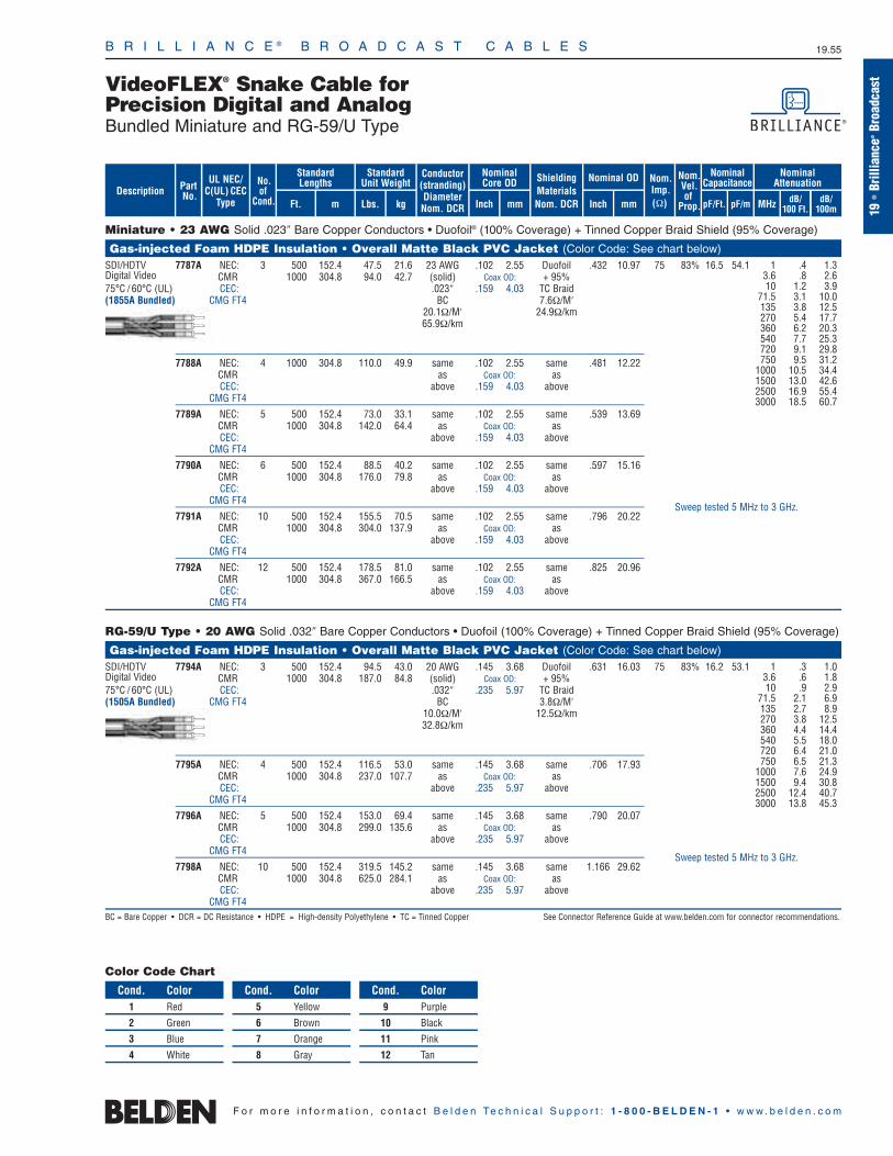
B R I L L I A N C E ® B R O A D C A S T C A B L E S 19.55
19•
Brill
ianc
e®Br
oadc
astVideoFLEX® Snake Cable for
Precision Digital and AnalogBundled Miniature and RG-59/U Type
F o r m o r e i n f o r m a t i o n , c o n t a c t B e l d e n Te c h n i c a l S u p p o r t : 1 - 8 0 0 - B E L D E N - 1 • w w w . b e l d e n . c o m
Conductor(stranding)DiameterNom. DCR
ShieldingMaterialsNom. DCR
No.of
Cond.
Nom.Imp.(Ω)
Nominal Core OD Nominal OD
Inch mm Inch mm
StandardUnit Weight
Standard Lengths
Lbs. kgFt. m
UL NEC/C(UL) CEC
Type MHz dB/100 Ft.
dB/100m
Nominal Attenuation
Nominal Capacitance
pF/mpF/Ft.
Nom.Vel.of
Prop.
Miniature • 23 AWG Solid .023″ Bare Copper Conductors • Duofoil® (100% Coverage) + Tinned Copper Braid Shield (95% Coverage)
Gas-injected Foam HDPE Insulation • Overall Matte Black PVC Jacket (Color Code: See chart below)SDI/HDTV 7787A NEC: 3 500 152.4 47.5 21.6 23 AWG .102 2.55 Duofoil .432 10.97 75 83% 16.5 54.1Digital Video CMR 1000 304.8 94.0 42.7 (solid) Coax OD: + 95% 75°C / 60°C (UL) CEC: .023″ .159 4.03 TC Braid(1855A Bundled) CMG FT4 BC 7.6Ω/M′
20.1Ω/M′ 24.9Ω/km. 65.9Ω/km
7788A NEC: 4 1000 304.8 110.0 49.9 same .102 2.55 same .481 12.22CMR as Coax OD: asCEC: above .159 4.03 above
CMG FT4
7789A NEC: 5 500 152.4 73.0 33.1 same .102 2.55 same .539 13.69CMR 1000 304.8 142.0 64.4 as Coax OD: asCEC: above .159 4.03 above
CMG FT4
7790A NEC: 6 500 152.4 88.5 40.2 same .102 2.55 same .597 15.16CMR 1000 304.8 176.0 79.8 as Coax OD: asCEC: above .159 4.03 above
CMG FT4
7791A NEC: 10 500 152.4 155.5 70.5 same .102 2.55 same .796 20.22CMR 1000 304.8 304.0 137.9 as Coax OD: asCEC: above .159 4.03 above
CMG FT4
7792A NEC: 12 500 152.4 178.5 81.0 same .102 2.55 same .825 20.96CMR 1000 304.8 367.0 166.5 as Coax OD: asCEC: above .159 4.03 above
CMG FT4
RG-59/U Type • 20 AWG Solid .032″ Bare Copper Conductors • Duofoil (100% Coverage) + Tinned Copper Braid Shield (95% Coverage)
Gas-injected Foam HDPE Insulation • Overall Matte Black PVC Jacket (Color Code: See chart below)SDI/HDTV 7794A NEC: 3 500 152.4 94.5 43.0 20 AWG .145 3.68 Duofoil .631 16.03 75 83% 16.2 53.1Digital Video CMR 1000 304.8 187.0 84.8 (solid) Coax OD: + 95%75°C / 60°C (UL) CEC: .032″ .235 5.97 TC Braid(1505A Bundled) CMG FT4 BC 3.8Ω/M′
10.0Ω/M′ 12.5Ω/km32.8Ω/km
7795A NEC: 4 500 152.4 116.5 53.0 same .145 3.68 same .706 17.93CMR 1000 304.8 237.0 107.7 as Coax OD: asCEC: above .235 5.97 above
CMG FT4
7796A NEC: 5 500 152.4 153.0 69.4 same .145 3.68 same .790 20.07CMR 1000 304.8 299.0 135.6 as Coax OD: asCEC: above .235 5.97 above
CMG FT4
7798A NEC: 10 500 152.4 319.5 145.2 same .145 3.68 same 1.166 29.62CMR 1000 304.8 625.0 284.1 as Coax OD: asCEC: above .235 5.97 above
CMG FT4BC = Bare Copper • DCR = DC Resistance • HDPE = High-density Polyethylene • TC = Tinned Copper See Connector Reference Guide at www.belden.com for connector recommendations.
PartNo. dB/
100m
Description
Color Code Chart
Cond. Color1 Red
2 Green
3 Blue
4 White
Cond. Color5 Yellow
6 Brown
7 Orange
8 Gray
Cond. Color9 Purple
10 Black
11 Pink
12 Tan
1 .4 1.33.6 .8 2.610 1.2 3.9
71.5 3.1 10.0135 3.8 12.5270 5.4 17.7360 6.2 20.3540 7.7 25.3720 9.1 29.8750 9.5 31.2
1000 10.5 34.41500 13.0 42.62500 16.9 55.43000 18.5 60.7
1 .3 1.03.6 .6 1.810 .9 2.9
71.5 2.1 6.9135 2.7 8.9270 3.8 12.5360 4.4 14.4540 5.5 18.0720 6.4 21.0750 6.5 21.3
1000 7.6 24.91500 9.4 30.82500 12.4 40.73000 13.8 45.3
Sweep tested 5 MHz to 3 GHz.
Sweep tested 5 MHz to 3 GHz.
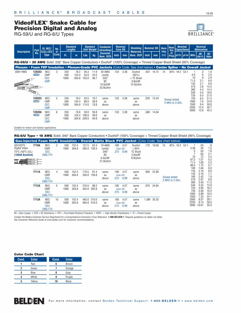
B R I L L I A N C E ® B R O A D C A S T C A B L E S 19.56
F o r m o r e i n f o r m a t i o n , c o n t a c t B e l d e n Te c h n i c a l S u p p o r t : 1 - 8 0 0 - B E L D E N - 1 • w w w . b e l d e n . c o m
RG-59/U • 20 AWG Solid .032″ Bare Copper Conductors • Duofoil® (100% Coverage) + Tinned Copper Braid Shield (95% Coverage)
Plenum • Foam FEP Insulation • Plenum-Grade PVC Jackets (Color Code: See chart below) • Center Spline • No Overall Jacket300V RMS 1283S3 NEC: 3 250 76.2 26.3 11.9 20 AWG .133 3.38 Duofoil .422 10.72 75 83% 16.2 53.1
u CMP 500 152.4 54.0 24.5 (solid) (95%)CEC: 1000 304.8 103.0 46.7 .032″ + TC BraidCMP BC 3.8Ω/M′
10.0Ω/M′ 12.5Ω/km32.8Ω/km
1283S5 NEC: 5 250 76.2 43.5 19.7 same .133 3.38 same .529 13.44u CMP 500 152.4 88.0 39.9 as as
CEC: 1000 304.8 174.0 78.9 above aboveCMP
1283S6 NEC: 6 250 76.6 59.0 26.8 same .133 3.38 same .588 14.94u CMP 500 152.4 108.0 49.0 as as
CEC: 1000 304.8 209.0 94.8 above aboveCMP
Suitable for Indoor and Outdoor applications.
RG-6/U Type • 18 AWG Solid .040″ Bare Copper Conductors • Duofoil® (100% Coverage) + Tinned Copper Braid Shield (95% Coverage)
Gas-injected Foam HDPE Insulation • Overall Matte Black PVC Jacket (Color Code: See chart below)SDI/HDTV 7710A NEC: 3 500 152.4 137.5 62.4 18 AWG .180 4.57 Duofoil .770 19.56 75 82% 16.2 53.1Digital Video CMR 1000 304.8 285.0 129.3 (solid) Coax OD: + 95%75°C / 60°C (UL) CEC: .040″ .275 6.99 TC Braid(1694A Bundled) CMG FT4 BC 3.0Ω/M′
6.4Ω/M′ 9.9Ω/km21.0Ω/km
7711A NEC: 4 500 152.4 179.5 81.4 same .180 4.57 same .900 22.86CMR 1000 304.8 350.0 158.8 as Coax OD: asCEC: above .275 6.99 above
CMG FT4
7712A NEC: 5 500 152.4 216.5 98.2 same .180 4.57 same .970 24.64CMR 1000 304.8 454.0 205.9 as Coax OD: asCEC: above .275 6.99 above
CMG FT4
7713A NEC: 10 500 152.4 463.0 210.0 same .180 4.57 same 1.386 35.20CMR 1000 304.8 904.0 410.0 as Coax OD: asCEC: above .275 6.99 above
CMG FT4BC = Bare Copper • DCR = DC Resistance • FEP = Fluorinated Ethylene Propylene • HDPE = High-density Polyethylene • TC = Tinned Copper
Contact the Belden Customer Service Department for a Comprehensive Connector Cross Reference. 1-800-BELDEN-1. Request quotations of cables not listed.See Connector Reference Guide at www.belden.com for connector recommendations.
Color Code Chart
Cond. Color1 Red
2 Green
3 Blue
4 White
5 Yellow
Cond. Color6 Brown
7 Orange
8 Gray
9 Purple
10 Black
1 .24 .83.58 .45 1.5
5 .54 1.87 .63 2.1
10 .72 2.467.5 1.57 5.271.5 1.60 5.388.5 1.75 5.7100 1.84 6.0135 2.10 6.9143 2.16 7.1180 2.42 7.9270 2.97 9.8360 3.43 11.3540 4.25 13.9720 4.95 16.2750 5.00 16.4
1000 5.89 19.31500 7.33 24.12000 8.57 28.12250 9.14 30.03000 10.67 35.0
Sweep tested 5 MHz to 3 GHz.
Conductor(stranding)DiameterNom. DCR
ShieldingMaterialsNom. DCR
No.of
Cond.
Nom.Imp.(Ω)
Nominal Core OD Nominal OD
Inch mm Inch mm
StandardUnit Weight
Standard Lengths
Lbs. kgFt. m
UL NEC/C(UL) CEC
Type MHz dB/100 Ft.
dB/100m
Nominal Attenuation
Nominal Capacitance
pF/mpF/Ft.
Nom.Vel.of
Prop.
PartNo. dB/
100m
Description
VideoFLEX® Snake Cable for Precision Digital and AnalogRG-59/U and RG-6/U Types
1 .3 1.0 3.6 .6 2.0 10 .9 2.9
71.5 2.1 6.9135 2.7 8.9 270 3.8 12.5 360 4.4 14.4 540 5.5 18.0 720 6.4 21.0 750 6.5 21.3
1000 7.6 24.9 1500 9.4 30.8 2500 12.4 40.7 3000 13.8 45.3
Sweep tested. 5 MHz to 3 GHz.
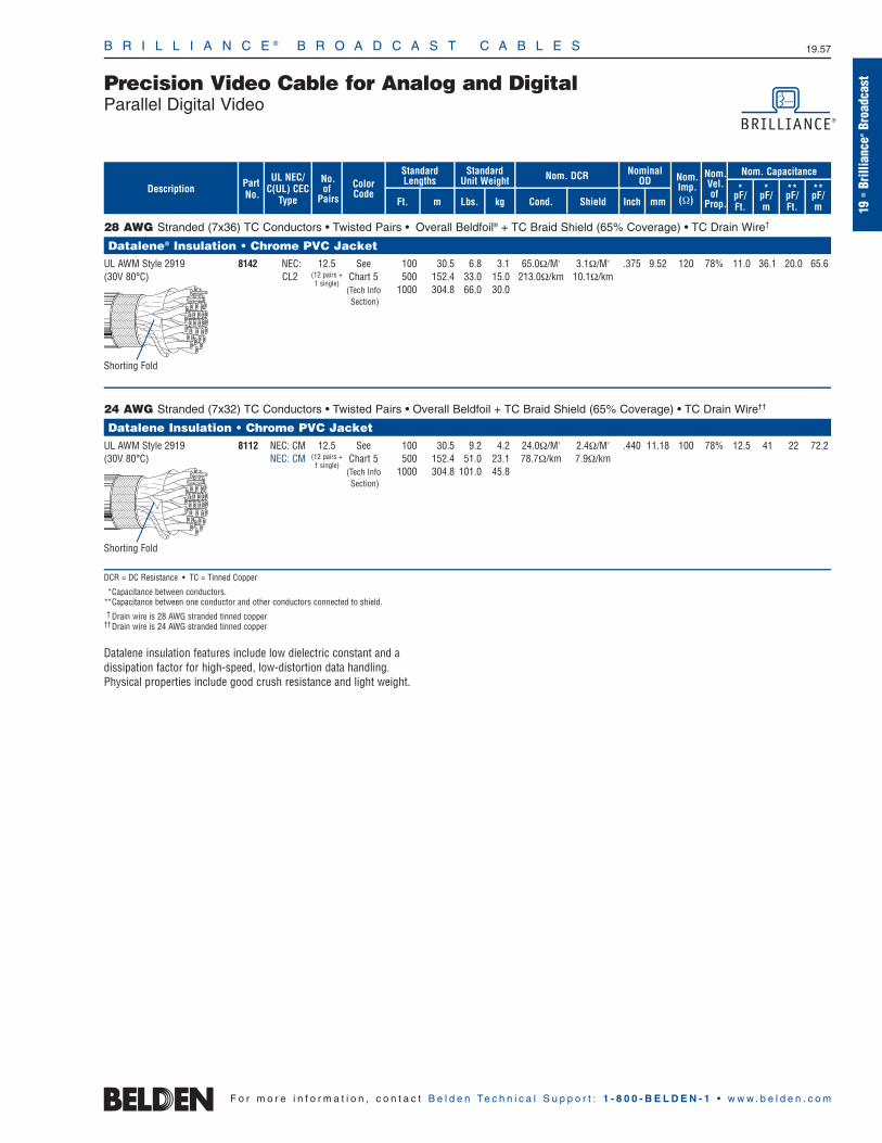
B R I L L I A N C E ® B R O A D C A S T C A B L E S 19.57
19•
Brill
ianc
e®Br
oadc
astPrecision Video Cable for Analog and Digital
Parallel Digital Video
F o r m o r e i n f o r m a t i o n , c o n t a c t B e l d e n Te c h n i c a l S u p p o r t : 1 - 8 0 0 - B E L D E N - 1 • w w w . b e l d e n . c o m
28 AWG Stranded (7x36) TC Conductors • Twisted Pairs • Overall Beldfoil® + TC Braid Shield (65% Coverage) • TC Drain Wire†
Datalene® Insulation • Chrome PVC JacketUL AWM Style 2919 8142 NEC: 12.5 See 100 30.5 6.8 3.1 65.0Ω/M′ 3.1Ω/M′ .375 9.52 120 78% 11.0 36.1 20.0 65.6(30V 80°C) CL2 (12 pairs + Chart 5 500 152.4 33.0 15.0 213.0Ω/km 10.1Ω/km
1 single)(Tech Info 1000 304.8 66.0 30.0Section)
24 AWG Stranded (7x32) TC Conductors • Twisted Pairs • Overall Beldfoil + TC Braid Shield (65% Coverage) • TC Drain Wire††
Datalene Insulation • Chrome PVC Jacket UL AWM Style 2919 8112 NEC: CM 12.5 See 100 30.5 9.2 4.2 24.0Ω/M′ 2.4Ω/M′ .440 11.18 100 78% 12.5 41 22 72.2(30V 80°C) NEC: CM (12 pairs + Chart 5 500 152.4 51.0 23.1 78.7Ω/km 7.9Ω/km
1 single)(Tech Info 1000 304.8 101.0 45.8Section)
DCR = DC Resistance • TC = Tinned Copper
*Capacitance between conductors. **Capacitance between one conductor and other conductors connected to shield.† Drain wire is 28 AWG stranded tinned copper
††Drain wire is 24 AWG stranded tinned copper
Datalene insulation features include low dielectric constant and a dissipation factor for high-speed, low-distortion data handling. Physical properties include good crush resistance and light weight.
UL NEC/C(UL) CEC
Type
Part No.
No.of
Pairs Ft. m
Standard Lengths
StandardUnit Weight
Lbs. kg
Nom. DCR
Cond. ShieldDescription Color
Code
Nominal OD
Inch mm
Nom.Imp.(Ω)
Nom.Vel.of
Prop.
Nom. Capacitance
*pF/Ft.
*pF/m
**pF/Ft.
**pF/m
Shorting Fold
Shorting Fold

B R I L L I A N C E ® B R O A D C A S T C A B L E S 19.58
ShieldingMaterialsNom. DCR
110 Ohm • 26 AWG Stranded (7x34) .018″ TC Conductors • Twisted Pair • Beldfoil® Shield (100% Coverage) • 26 AWG Stranded TC Drain Wire
Datalene® Insulation (Color Code: Black, White) • PVC Jacket (Chrome or Purple)75°C 9180 NEC: 1000 304.8 10.0 4.5 26 AWG .049 1.24 Beldfoil .144 3.66 110 76% 13.0 42.7
CMR (7x34) w/StrandedCEC: .018″ TC Drain
CMG FT4 TC Wire37.3Ω/M′ 23.1Ω/M′
122.3Ω/km 75.8Ω/km
Twinax • 124 Ohm • 16 AWG Solid .051″ BC Conductors • Duofoil® (100% Coverage) + TC Braid Shield (90% Coverage)
Foam Polyethylene Insulation (Color Code: Clear, Blue) • Black PVC JacketUL AWM 9860 NEC: 500 152.4 52.0 23.6 16 AWG .322 8.18 Duofoil .440 11.18 124 78% 10.9 35.8Style 2448 CMX 1000 304.8 103.0 46.8 (solid) + 90%(30V 60°C) CEC: 2000 609.6 202.0 91.8 .051″ TC Braid
CMX BC 1.3Ω/M′4.2Ω/M′ 4.3Ω/km
13.8Ω/km
BC = Bare Copper • DCR = DC Resistance • TC = Tinned Copper
Contact the Belden Customer Service Department for a Comprehensive Connector Cross Reference. 1-800-BELDEN-1.
Nom.Imp.(Ω)
Nominal Core OD Nominal OD
Inch mm Inch mm
Conductor(stranding)DiameterNom. DCR
StandardUnit WeightStandard Lengths
Lbs. kgFt. m
UL NEC/C(UL) CEC
Type
PartNo.
MHz dB/100 Ft.
dB/100m
Nominal Attenuation
Nominal Capacitance
pF/mpF/Ft.
Nom.Vel.of
Prop.Description
F o r m o r e i n f o r m a t i o n , c o n t a c t B e l d e n Te c h n i c a l S u p p o r t : 1 - 8 0 0 - B E L D E N - 1 • w w w . b e l d e n . c o m
.38 .8 2.6
.77 1.2 4.01.0 1.3 4.31.5 1.5 5.02.0 1.7 5.63.1 1.9 6.34.1 2.1 7.05.6 2.4 8.08.2 2.8 9.3
11.3 3.1 10.312.3 3.2 10.624.6 4.2 14.0
1 .2 .610 .7 2.350 1.8 5.9
100 2.9 9.5200 4.1 13.5400 6.2 20.3
Shorting Fold
Maximum Transmission Distance at Serial Digital Data Rates
1865A 810 247 760 232 600 183 520 158 420 128 170 52
8279 910 277 810 247 640 195 550 168 440 134 170 52
1855A–7787A 1000 305 910 277 750 229 650 198 530 162 210 64
9209 1030 314 930 283 750 229 650 198 540 165 200 61
9209A 1030 314 930 283 750 229 650 198 540 165 200 61
1505A–7794A 1430 436 1320 402 1110 338 960 293 790 241 300 91
1505F 1200 366 1071 326 857 261 732 223 588 179 225 69
1506A 1360 415 1200 366 940 286 810 247 670 204 270 82
9231 1430 436 1270 387 1000 305 850 259 680 207 260 79
9141 1430 436 1270 387 1000 305 850 259 680 207 260 79
8281 1430 436 1270 387 1000 305 860 262 700 213 260 79
8281B 1430 436 1270 387 1000 305 850 259 680 207 250 76
8281F 1250 381 1100 335 860 262 730 222 590 180 240 73
88281 1300 396 1150 351 910 277 770 235 600 183 200 61
1694A–7710A 1760 536 1620 494 1360 415 1180 360 970 296 370 113
1695A 1670 509 1520 463 1250 381 1080 329 880 268 310 94
7855A 2220 677 2000 610 1670 509 1460 445 1210 369 470 143
7731A 2730 832 2460 750 2000 610 1740 530 1430 436 540 165
7732A 2420 738 2140 652 1690 515 1440 439 1150 351 430 131*Values proposed at time of printing.The serial digital interconnect standards are designed to operate where the signal loss at 1/2 the clock frequency does not exceed the approximate loss values listed below. The maximum length values shown are based on typical attenuation values for the cables listed and the following criteria:
Maximum length = 30 dB loss at 1/2 the clock frequency: SMPTE 259M, PAL, Widescreen.Maximum length = 20 dB loss at 1/2 the clock frequency: SMPTE 292M.
The bit error rate (BER) can vary dramatically as the calculated distances are approached. BER is dependent on receiver design and the losses of the actual coax used. Distribution and routing equipment manufacturers should be contacted to verify their maximum recommended transmission.
Data Rate: 143 Mb/s
SMPTE 259M
Composite NTSC
Ft. m
177 Mb/s 270 Mb/s 360 Mb/s 540 Mb/s 1.5 Gb/s
Spec:
Application:
Part No.
ITU-R BT. 601
Composite PAL
Ft. m
SMPTE 259M
Component Video
Ft. m
SMPTE 259M
Component Widescreen
Ft. m
SMPTE 344M*
Component Widescreen
Ft. m
SMPTE 292M
HDTV
Ft. m
Precision Video Cable for Analog and DigitalDigital Video Time Code and Precision Video Twinax
Return Loss Headroom — Refer to graph on page 19.78.
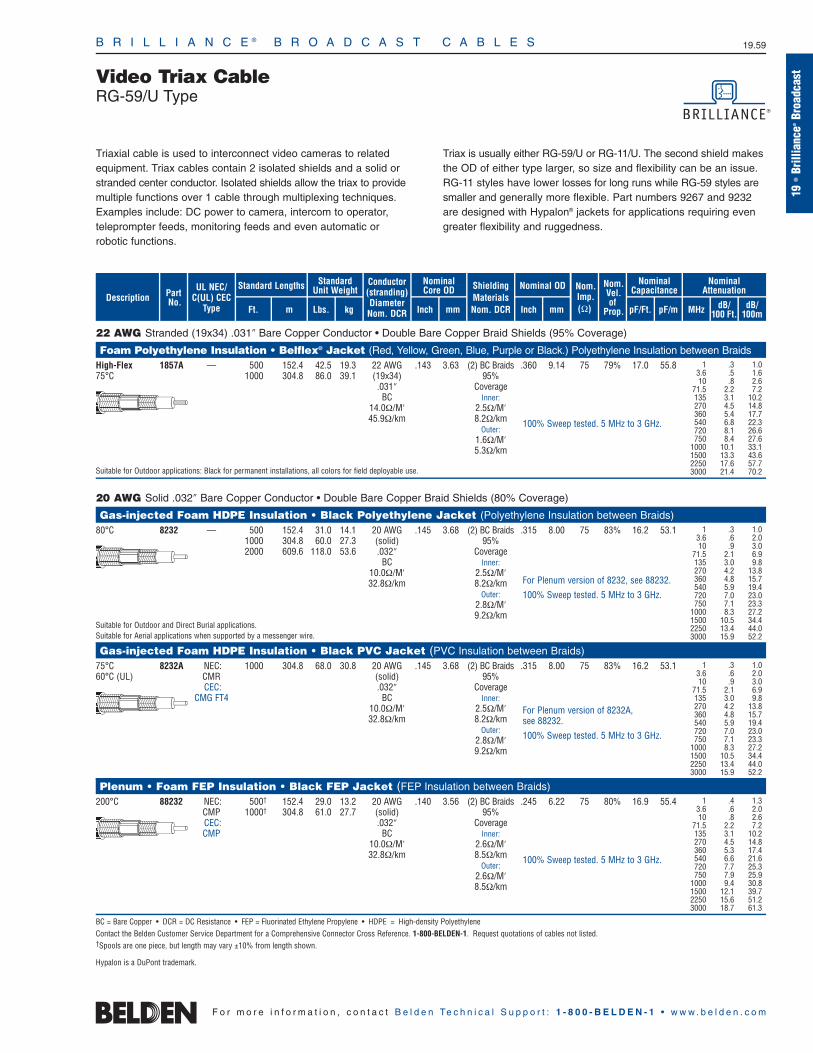
B R I L L I A N C E ® B R O A D C A S T C A B L E S 19.59
19•
Brill
ianc
e®Br
oadc
astVideo Triax Cable
RG-59/U Type
F o r m o r e i n f o r m a t i o n , c o n t a c t B e l d e n Te c h n i c a l S u p p o r t : 1 - 8 0 0 - B E L D E N - 1 • w w w . b e l d e n . c o m
22 AWG Stranded (19x34) .031″ Bare Copper Conductor • Double Bare Copper Braid Shields (95% Coverage)
Foam Polyethylene Insulation • Belflex® Jacket (Red, Yellow, Green, Blue, Purple or Black.) Polyethylene Insulation between BraidsHigh-Flex 1857A — 500 152.4 42.5 19.3 22 AWG .143 3.63 (2) BC Braids .360 9.14 75 79% 17.0 55.875°C 1000 304.8 86.0 39.1 (19x34) 95%
.031″ CoverageBC Inner:
14.0Ω/M′ 2.5Ω/M′45.9Ω/km 8.2Ω/km
Outer:1.6Ω/M′5.3Ω/km
Suitable for Outdoor applications: Black for permanent installations, all colors for field deployable use.
20 AWG Solid .032″ Bare Copper Conductor • Double Bare Copper Braid Shields (80% Coverage)
Gas-injected Foam HDPE Insulation • Black Polyethylene Jacket (Polyethylene Insulation between Braids)80°C 8232 — 500 152.4 31.0 14.1 20 AWG .145 3.68 (2) BC Braids .315 8.00 75 83% 16.2 53.1
1000 304.8 60.0 27.3 (solid) 95%2000 609.6 118.0 53.6 .032″ Coverage
BC Inner:10.0Ω/M′ 2.5Ω/M′32.8Ω/km 8.2Ω/km
Outer:2.8Ω/M′9.2Ω/km
Suitable for Outdoor and Direct Burial applications. Suitable for Aerial applications when supported by a messenger wire.
Gas-injected Foam HDPE Insulation • Black PVC Jacket (PVC Insulation between Braids)75°C 8232A NEC: 1000 304.8 68.0 30.8 20 AWG .145 3.68 (2) BC Braids .315 8.00 75 83% 16.2 53.160°C (UL) CMR (solid) 95%
CEC: .032″ CoverageCMG FT4 BC Inner:
10.0Ω/M′ 2.5Ω/M′32.8Ω/km 8.2Ω/km
Outer:2.8Ω/M′9.2Ω/km
Plenum • Foam FEP Insulation • Black FEP Jacket (FEP Insulation between Braids)200°C 88232 NEC: 500† 152.4 29.0 13.2 20 AWG .140 3.56 (2) BC Braids .245 6.22 75 80% 16.9 55.4
CMP 1000† 304.8 61.0 27.7 (solid) 95% CEC: .032″ CoverageCMP BC Inner:
10.0Ω/M′ 2.6Ω/M′32.8Ω/km 8.5Ω/km
Outer:2.6Ω/M′8.5Ω/km
BC = Bare Copper • DCR = DC Resistance • FEP = Fluorinated Ethylene Propylene • HDPE = High-density PolyethyleneContact the Belden Customer Service Department for a Comprehensive Connector Cross Reference. 1-800-BELDEN-1. Request quotations of cables not listed.†Spools are one piece, but length may vary ±10% from length shown.
1 .3 1.03.6 .5 1.610 .8 2.6
71.5 2.2 7.2135 3.1 10.2270 4.5 14.8360 5.4 17.7540 6.8 22.3720 8.1 26.6750 8.4 27.6
1000 10.1 33.11500 13.3 43.62250 17.6 57.73000 21.4 70.2
1 .3 1.03.6 .6 2.010 .9 3.0
71.5 2.1 6.9135 3.0 9.8270 4.2 13.8360 4.8 15.7540 5.9 19.4720 7.0 23.0750 7.1 23.3
1000 8.3 27.21500 10.5 34.42250 13.4 44.03000 15.9 52.2
1 .3 1.03.6 .6 2.010 .9 3.0
71.5 2.1 6.9135 3.0 9.8270 4.2 13.8360 4.8 15.7540 5.9 19.4720 7.0 23.0750 7.1 23.3
1000 8.3 27.21500 10.5 34.42250 13.4 44.03000 15.9 52.2
1 .4 1.33.6 .6 2.010 .8 2.6
71.5 2.2 7.2135 3.1 10.2270 4.5 14.8360 5.3 17.4540 6.6 21.6720 7.7 25.3750 7.9 25.9
1000 9.4 30.81500 12.1 39.72250 15.6 51.23000 18.7 61.3
For Plenum version of 8232A, see 88232.
100% Sweep tested. 5 MHz to 3 GHz.
For Plenum version of 8232, see 88232.
100% Sweep tested. 5 MHz to 3 GHz.
100% Sweep tested. 5 MHz to 3 GHz.
100% Sweep tested. 5 MHz to 3 GHz.
ShieldingMaterialsNom. DCR
Nom.Imp.(Ω)
Nominal Core OD Nominal OD
Inch mm Inch mm
Conductor(stranding)DiameterNom. DCR
StandardUnit WeightStandard Lengths
Lbs. kgFt. m
UL NEC/C(UL) CEC
Type
PartNo.
MHz dB/100 Ft.
dB/100m
Nominal Attenuation
Nominal Capacitance
pF/mpF/Ft.
Nom.Vel.of
Prop.Description
Triaxial cable is used to interconnect video cameras to relatedequipment. Triax cables contain 2 isolated shields and a solid orstranded center conductor. Isolated shields allow the triax to providemultiple functions over 1 cable through multiplexing techniques.Examples include: DC power to camera, intercom to operator,teleprompter feeds, monitoring feeds and even automatic or robotic functions.
Triax is usually either RG-59/U or RG-11/U. The second shield makesthe OD of either type larger, so size and flexibility can be an issue.RG-11 styles have lower losses for long runs while RG-59 styles aresmaller and generally more flexible. Part numbers 9267 and 9232are designed with Hypalon® jackets for applications requiring evengreater flexibility and ruggedness.
Hypalon is a DuPont trademark.
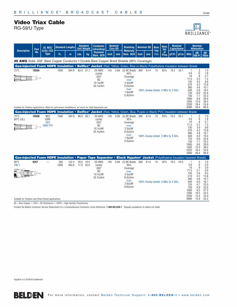
B R I L L I A N C E ® B R O A D C A S T C A B L E S 19.60
F o r m o r e i n f o r m a t i o n , c o n t a c t B e l d e n Te c h n i c a l S u p p o r t : 1 - 8 0 0 - B E L D E N - 1 • w w w . b e l d e n . c o m
20 AWG Solid .032″ Bare Copper Conductor • Double Bare Copper Braid Shields (95% Coverage)
Gas-injected Foam HDPE Insulation • Belflex® Jacket (Red, Yellow, Green, Blue or Black) Polyethylene Insulation between Braids
75°C 1856A — 1000 304.8 83.0 37.7 20 AWG .145 3.68 (2) BC Braids .360 9.14 75 83% 16.2 53.1(solid) 95% .032″ Coverage
BC Inner:10.1Ω/M′ 2.5Ω/M′33.1Ω/km 8.2Ω/km
Outer:1.6Ω/M′5.3Ω/km
Suitable for Outdoor applications: Black for permanent installations, all colors for field deployable use.
Gas-injected Foam HDPE Insulation • Belflex® Jacket (Red, Yellow, Green, Blue, Purple or Black) PVC Insulation between Braids
75°C 1856B NEC: 1000 304.8 86.0 39.1 20 AWG .145 3.68 (2) BC Braids .360 9.14 75 83% 16.2 53.160°C (UL) CMR (solid) 95%
CEC: .032″ CoverageCMG FT4 BC Inner:
10.1Ω/M′ 2.5Ω/M′33.1Ω/km 8.2Ω/km
Outer:1.6Ω/M′5.2Ω/km
Gas-injected Foam HDPE Insulation • Paper Tape Separator • Black Hypalon® Jacket (Polyethylene Insulation between Braids)
80°C 9267 — 500 152.4 39.5 18.0 20 AWG .145 3.68 (2) BC Braids .360 9.14 75 82% 16.3 53.5VW-1 1000 304.8 77.0 35.0 (solid) 95%
.032″ CoverageBC Inner:
10.1Ω/M′ 2.5Ω/M′33.1Ω/km 8.3Ω/km
Outer:2.6Ω/M′8.6Ω/km
Suitable for Outdoor and Direct Burial applications.
BC = Bare Copper • DCR = DC Resistance • HDPE = High-density Polyethylene
Contact the Belden Customer Service Department for a Comprehensive Connector Cross Reference. 1-800-BELDEN-1. Request quotations of cables not listed.
1 .3 1.03.6 .6 1.810 .8 2.7
71.5 2.2 7.2135 3.0 9.8270 4.2 13.8360 4.8 15.7540 5.9 19.4720 6.9 22.6750 7.1 23.3
1000 8.8 28.91500 12.0 39.42250 16.4 53.83000 20.4 66.9
1 .3 1.03.6 .6 1.810 .8 2.7
71.5 2.2 7.2135 3.0 9.8270 4.2 13.8360 4.8 15.7540 5.9 19.4720 6.9 22.6750 7.1 23.3
1000 8.8 28.91500 12.0 39.42250 16.4 53.83000 20.4 66.9
1 .3 1.03.6 .6 2.010 .9 3.0
71.5 2.1 6.9135 2.9 9.5270 4.2 13.8360 4.8 15.7540 6.0 19.7720 6.7 22.0750 6.9 22.6
1000 8.3 27.21500 10.5 34.42250 13.4 44.03000 15.9 52.2
Hypalon is a DuPont trademark.
100% Sweep tested. 5 MHz to 3 GHz.
100% Sweep tested. 5 MHz to 3 GHz.
100% Sweep tested. 5 MHz to 3 GHz.
ShieldingMaterialsNom. DCR
Nom.Imp.(Ω)
Nominal Core OD Nominal OD
Inch mm Inch mm
Conductor(stranding)DiameterNom. DCR
StandardUnit WeightStandard Lengths
Lbs. kgFt. m
UL NEC/C(UL) CEC
Type
PartNo.
MHz dB/100 Ft.
dB/100m
Nominal Attenuation
Nominal Capacitance
pF/mpF/Ft.
Nom.Vel.of
Prop.Description
Video Triax CableRG-59/U Type

B R I L L I A N C E ® B R O A D C A S T C A B L E S 19.61
19•
Brill
ianc
e®Br
oadc
astVideo Triax Cable
RG-11/U Type
F o r m o r e i n f o r m a t i o n , c o n t a c t B e l d e n Te c h n i c a l S u p p o r t : 1 - 8 0 0 - B E L D E N - 1 • w w w . b e l d e n . c o m
15 AWG Stranded (19x27) .064″ Bare Copper Conductor • Double Bare Copper Braid Shield (95% Coverage)
Gas-injected Foam HDPE Insulation • Belflex® Jacket (Red, Yellow, Green, Blue, Purple or Black) Polyethylene Insulation between Braids
High-Flex 1858A — 500 152.4 80.5 36.5 15 AWG .312 7.92 (2) BC Braids .520 13.20 75 78% 17.3 56.875°C 1000 304.8 157.0 71.2 (19x27) 95%
.064″ CoverageBC Inner:
3.1Ω/M′ 1.8Ω/M′8.9Ω/km 5.2Ω/km
Outer:1.4Ω/M′4.6Ω/km
Suitable for Outdoor applications: Black for permanent installations, all colors for field deployable use.
Plenum • Foam FEP Teflon® Insulation • Black Fluorocopolymer Jacket (Fluorocopolymer Insulation between Braids)125°C 1859A NEC: 500 152.4 66.5 30.2 15 AWG .285 7.24 (2) BC Braids .406 10.30 75 80% 16.5 54.1
CMP 1000 304.8 134.0 60.9 (19x27) 95% CEC: .064″ Coverage
CMP FT6 BC Inner:3.1Ω/M′ 1.4Ω/M′8.9Ω/km 4.6Ω/km
Outer:1.4Ω/M′
Suitable for Outdoor and Direct Burial applications. 4.6Ω/kmSuitable for Aerial applications when supported by a messenger wire.
15 AWG Stranded (19x27) .064″ Bare Copper Conductor • Double Bare Copper Braid Shield (90% Coverage)
Gas-injected Foam HDPE Insulation • Yellow PVC Jacket (Polyethylene Insulation between Braids)UL AWM 9192 NEC: 1000 304.8 150.0 68.2 15 AWG .312 7.92 (2) BC Braids .520 13.20 75 78% 17.3 56.8Style 1641 CL2X (19x27) 90% (30V 75°C) .064″ CoverageVW-1 BC Inner:
3.1Ω/M′ 1.6Ω/M′8.9Ω/km 5.2Ω/km
Outer:1.6Ω/M′5.2Ω/km
Suitable for Outdoor applications: Black for permanent installations, all colors for field deployable use.
Gas-injected Foam HDPE Insulation • Paper Tape Separator • Black Hypalon® Jacket (Polyethylene Insulation between Braids)UL AWM 9232 — 500 152.4 76.5 34.7 15 AWG .312 7.92 (2) BC Braids .520 13.20 75 78% 17.3 56.8Style 1641 1000 304.8 145.0 65.9 (19x27) 90% (30V 75°C) .064″ CoverageVW-1 BC Inner:
3.1Ω/M′ 1.6Ω/M′8.9Ω/km 5.2Ω/km
Outer:1.6Ω/M′5.2Ω/km
Suitable for Outdoor and Direct Burial applications.
BC = Bare Copper • DCR = DC Resistance • FEP = Fluorinated Ethylene Propylene • HDPE = High-density Polyethylene
Contact the Belden Customer Service Department for a Comprehensive Connector Cross Reference. 1-800-BELDEN-1. Request quotations of cables not listed.
1 .1 .53.6 .3 1.010 .5 1.6
71.5 1.2 3.9135 1.8 5.9270 2.6 8.5360 3.1 10.2540 3.9 12.8720 4.7 15.4750 4.8 15.7
1000 5.7 18.7
1 .1 .53.6 .3 1.010 .5 1.6
71.5 1.2 3.9135 1.8 5.9270 2.6 8.5360 3.1 10.2540 3.9 12.8720 4.7 15.4750 4.8 15.7
1000 5.7 18.7
1 .1 .53.6 .3 1.010 .5 1.6
71.5 1.2 3.9135 1.8 5.9270 2.6 8.5360 3.1 10.2540 3.9 12.8720 4.7 15.4750 4.8 15.7
1000 5.7 18.7
1 .1 .53.6 .2 .710 .5 1.6
71.5 1.3 4.3135 1.9 6.2270 3.0 9.8360 3.6 11.8540 4.5 14.8720 5.4 17.7750 5.6 18.4
1000 6.6 21.6
Hypalon is a DuPont trademark.
Teflon is a DuPont trademark.
100% Sweep tested. 5 MHz to 850 MHz.
100% Sweep tested. 5 MHz to 850 MHz.
100% Sweep tested. 5 MHz to 850 MHz.
100% Sweep tested. 5 MHz to 850 MHz.
ShieldingMaterialsNom. DCR
Nom.Imp.(Ω)
Nominal Core OD Nominal OD
Inch mm Inch mm
Conductor(stranding)DiameterNom. DCR
StandardUnit WeightStandard Lengths
Lbs. kgFt. m
UL NEC/C(UL) CEC
Type
PartNo.
MHz dB/100 Ft.
dB/100m
Nominal Attenuation
Nominal Capacitance
pF/mpF/Ft.
Nom.Vel.of
Prop.Description

B R I L L I A N C E ® B R O A D C A S T C A B L E S 19.62
F o r m o r e i n f o r m a t i o n , c o n t a c t B e l d e n Te c h n i c a l S u p p o r t : 1 - 8 0 0 - B E L D E N - 1 • w w w . b e l d e n . c o m
14 AWG Solid .064″ Bare Copper Conductor • Double Bare Copper Shield (95% Coverage)
Gas-injected Foam HDPE Insulation • Black Polyethylene Jacket (Polyethylene Insulation between Braids)
80°C 8233 — 500 152.4 63.0 28.6 14 AWG .285 7.24 (2) BC Braids .475 12.07 75 84% 16.1 52.81000 304.8 122.0 55.5 (solid) 95% 2000 609.6 240.0 109.1 .064″ Coverage
BC Inner:2.5Ω/M′ 1.6Ω/M′8.2Ω/km 5.2Ω/km
Outer:1.4Ω/M′4.6Ω/km
Suitable for Outdoor and Direct Burial applications.
Gas-injected Foam HDPE Insulation • Black PVC Jacket (PVC Insulation between Braids)
75°C 8233A NEC: 1000 304.8 136.0 61.7 14 AWG .285 7.24 (2) BC Braids .475 12.07 75 84% 16.1 52.860°C (UL) CMR 2000 609.6 266.0 120.7 (solid) 95%
CEC: 4000 1219.2 572.0 259.5 .064″ CoverageCMG BC Inner:
2.5Ω/M′ 1.6Ω/M′8.2Ω/km 5.2Ω/km
Outer:1.4Ω/M′4.6Ω/km
Gas-injected Foam HDPE Insulation • Black Polyethylene Jacket (PE Insulation between Braids; Flooding Compound on Outer Braid)
Flooded 7803A — 500 152.4 64.0 29.1 14 AWG .285 7.24 (2) BC Braids .475 12.07 75 84% 16.1 52.880°C 1000 304.8 123.0 55.9 (solid) 95%
3000 914.4 381.0 173.2 .064″ CoverageBC Inner:
2.5Ω/M′ 1.6Ω/M′8.2Ω/km 5.2Ω/km
Outer:1.4Ω/M′4.6Ω/km
Suitable for Outdoor and Direct Burial applications.
BC = Bare Copper • DCR = DC Resistance • HDPE = High-density Polyethylene • PE = Polyethylene
Contact the Belden Customer Service Department for a Comprehensive Connector Cross Reference. 1-800-BELDEN-1. Request quotations of cables not listed.
1 .2 .73.6 .3 1.010 .4 1.3
71.5 1.1 3.6135 1.5 4.9270 2.3 7.5360 2.7 8.9540 3.5 11.5720 4.2 13.8750 4.3 14.1
1000 5.2 17.11500 7.1 23.32250 9.6 31.53000 12.0 39.4
1 .2 .73.6 .3 1.010 .4 1.3
71.5 1.1 3.6135 1.5 4.9270 2.3 7.5360 2.7 8.9540 3.5 11.5720 4.2 13.8750 4.3 14.1
1000 5.2 17.11500 7.1 23.32250 9.6 31.53000 12.0 39.4
1 .2 .73.6 .3 1.010 .4 1.3
71.5 1.1 3.6135 1.5 4.9270 2.3 7.5360 2.7 8.9540 3.5 11.5720 4.2 13.8750 4.3 14.1
1000 5.2 17.11500 7.1 23.32250 9.6 31.53000 12.0 39.4
100% Sweep tested. 5 MHz to 3 GHz.
100% Sweep tested. 5 MHz to 3 GHz.
100% Sweep tested. 5 MHz to 3 GHz.
ShieldingMaterialsNom. DCR
Nom.Imp.(Ω)
Nominal Core OD Nominal OD
Inch mm Inch mm
Conductor(stranding)DiameterNom. DCR
StandardUnit WeightStandard Lengths
Lbs. kgFt. m
UL NEC/C(UL) CEC
Type
PartNo.
MHz dB/100 Ft.
dB/100m
Nominal Attenuation
Nominal Capacitance
pF/mpF/Ft.
Nom.Vel.of
Prop.Description
Video Triax CableRG-11/U Type

B R I L L I A N C E ® B R O A D C A S T C A B L E S 19.63
19•
Brill
ianc
e®Br
oadc
astAudio and Video Composite Camera Cable
Overview
F o r m o r e i n f o r m a t i o n , c o n t a c t B e l d e n Te c h n i c a l S u p p o r t : 1 - 8 0 0 - B E L D E N - 1 • w w w . b e l d e n . c o m
Audio and Video Composite Camera Cables
Audio/video composite cables are used in camera cable applications requiring one or more coaxes for video and one or more shielded pairs for audio and power.
Applications for such cables include interconnect of remote fieldcameras for Electronic News Gathering (ENG), Electronic FieldProduction (EFP) and Closed Circuit Television (CCTV).
ENG cameras are used in shooting on-site News reports which may be live or recorded. EFP applications involve on-siterecording of videos produced for companies or private enterprises(i.e., advertisement or training films).
The three most common audio/video configurations are one coax-one pair, one coax-three pair and two coax-three pair designs.
One Coax-One Pair
The most common use for cable of this design is the interconnectionof cameras requiring one coax for the video connection to the cameraand one pair for audio.
The audio pair may be connected either to the camera itself, to an audio junction box or directly into a microphone.
Another common application for this design is the connection ofCCTV surveillance cameras where the coax is used for the videoconnection and the twisted pair to power the camera.
One Coax-Three Pair
This cable is used in camera applications requiring a coaxial videofeed, one audio pair for a MIC hook-up, and two audio pairs for theInterrupted Feedback (IFB) connections to the camera person andtalent (anchor). IFB is the audio feed(s) to the talent and cameraperson’s headset which enables them to listen and receive informationand directions from the news director as they make the recording.
Two Coax-Three Pair
Camera applications utilizing this design again utilize one coax forthe camera video connection and three audio pairs for the MIC andIFB hook-ups. The additional coax can be used to provide video toa portable TV monitor so the talent can view him or herself as thereport is being recorded.
HDTV Fiber/Copper Composite Cable
Designed specifically for high-definition cameras, these composite cables can multiplex audio and video signals and power. The cables meet all the requirements of the SMPTE 311 standard developed by the Society of Motion Picture and Television Engineers (SMPTE). They are also compatible with industry standard SMPTE 304M connectors.

Nominal OD
Inch mm
ShieldingMaterialsNom. DCR
B R I L L I A N C E ® B R O A D C A S T C A B L E S 19.64
dB/1000 Ft.
Nominal Optical Attenuation (@1310nm)
4 Power Conductors • SM Fiber w/24 and 20 AWG Stranded (7x32 and 19x32) TC Conductors • TC Braid Shield (95% Coverage)
PVC Insulation • Black Belflex® Jacket7804R NEC: 328 100.0 33.1 15.0 (2) Fibers: .035 .89 36 AWG .362 9.20 .14 .45
CMR 500 152.4 47.5 21.6 SM/125µ/900µ TC BraidCEC: 1000 304.8 96.0 43.5 (core/clad/buffer) 95% Shield
CMG FT4 1640 500.0 152.5 69.2 (2) Cond.: .050 1.27 Coverage3280 1000.0 314.9 142.8 24 AWG 2.9Ω/M′
(7x32) 9.5Ω/km.024″
Tinned Copper23.3Ω/M′76.4Ω/km
(4) Cond.: .063 1.6020 AWG(19x32).037″
Tinned Copper8.8Ω/M′
28.9Ω/km
2 Power Conductors • SM Fiber w/24 and 16 AWG Stranded (7x32 and 65x34) TC Conductors • TC Braid Shield (95% Coverage)
PVC Insulation • Black Belflex Jacket7804C NEC: 328 100.0 32.8 14.9 (2) Breakout .079 2.00 38 AWG .362 9.20 .14 .45
CMR 500 152.4 49.0 22.2 Fibers: TC BraidCEC: 1000 304.8 99.0 44.9 SM/125µ/900µ 95% Shield
CMG FT4 1640 500.0 157.4 71.4 (core/clad/buffer) Coverage3280 1000.0 324.7 147.3 (2) Cond.: .050 1.27 2.8Ω/M′
24 AWG 9.2Ω/km(7x32).024″
Tinned Copper23.3Ω/M′76.4Ω/km
(2) Cond.: .093 2.3616 AWG(65x34).059″
Tinned Copper4.3Ω/M′
Fibers and aramid fillers contained within a .008 in (2.0mm) diameter PVC breakout jacket. 14.1Ω/kmDCR = DC Resistance • SM = Single-mode • TC = Tinned Copper
Contact the Belden Customer Service Department for a Comprehensive Connector Cross Reference. 1-800-BELDEN-1. Request quotations of cables not listed.
Nominal Core OD
Inch mm
Conductor(stranding)Nom. DCR
StandardUnit WeightStandard Lengths
Lbs. kgFt. m
UL NEC/C(UL) CEC
Type
PartNo.
F o r m o r e i n f o r m a t i o n , c o n t a c t B e l d e n Te c h n i c a l S u p p o r t : 1 - 8 0 0 - B E L D E N - 1 • w w w . b e l d e n . c o m
dB/kmDescription
Plenum version and other conductor counts/diameters available by special order.
Plenum version and other conductor counts/diameters available by special order.
Audio and Video Composite Camera CableSMPTE 311M HDTV CablesSingle-mode Fiber with Copper Conductors

Composite Camera CableTelevision Camera and CCTV CablesRG-59/U Type Coax with Shielded Twisted Pair(s)
B R I L L I A N C E ® B R O A D C A S T C A B L E S 19.65
19•
Brill
ianc
e®Br
oadc
ast
F o r m o r e i n f o r m a t i o n , c o n t a c t B e l d e n Te c h n i c a l S u p p o r t : 1 - 8 0 0 - B E L D E N - 1 • w w w . b e l d e n . c o m
ShieldingMaterialsNom. DCR
22 AWG Stranded (7x30) Conductors • BC Coax w/BC Braid Shield (95% Coverage) • TC Twisted Pair w/Beldfoil® Shield (100% Cov.) +Drain Wire
Foam Polyethylene (Coax) and PVC (Pairs) Insulation • Black PVC JacketUL AWM 9265 NEC: 500 152.4 32.5 14.7 (1) Coax: .146 3.71 BC .242 6.15 75 78% 17.3 56.8Style 20006 CL2 1000 304.8 62.0 28.1 22 AWG Coax OD: Braid x x30V 60°C (7x30) .242 6.15 95% Shield .470 11.94
.030″ BC Coverage15.0Ω/M′ 2.6Ω/M′49.2Ω/km 8.5Ω/km
(2) Cond: .054 1.37 Pair: 35 58% 51.0 167.322 AWG Pair OD: Beldfoil(7x30) .112 2.84 Shielded
.030″ TC 100% Shield15.0Ω/M′ Coverage w/49.2Ω/km 22 AWG Drain WireBlack, Red 11.0Ω/M′
Siamese Type Construction 36.1Ω/km
22 AWG Stranded (7x30) Conductors • BC Coax w/BC Braid Shield (95% Cov.) • (3) TC STP Individually Beldfoil Shielded (100% Cov.) w/Drain Wire
Foam Polyethylene (Coax) and PVC (Pairs) Insulation • Black PVC JacketUL AWM 9165 NEC: 500 152.4 50.0 22.7 (1) Coax: .146 3.71 BC .290 7.37 75 78% 17.3 56.8Style 20006 CL2X 1000 304.8 94.0 42.7 22 AWG Coax OD: Braid x x30V 60°C (7x30) .242 6.15 95% Shield .561 14.25
.030″ BC Coverage15.0Ω/M′ 2.6Ω/M′49.2Ω/km 8.5Ω/km
(3) Pairs: .054 1.37 Each Pair: 35 58% 51.0 167.322 AWG Pair OD: Individually(7x30) .116 2.95 Beldfoil
.030″ TC Shielded 15.0Ω/M′ 100% Shield49.2Ω/km Coverage w/Red & Black, 22 AWG Drain Wire
Orange & Brown, 11.0Ω/M′Siamese Type Construction Green & White 36.1Ω/kmBC = Bare Copper • DCR = DC Resistance • STP = Shielded Twisted Pairs • TC = Tinned Copper
Contact the Belden Customer Service Department for a Comprehensive Connector Cross Reference. 1-800-BELDEN-1. Request quotations of cables not listed.
Nom.Imp.(Ω)
Nominal Core OD
OverallNominal OD
Inch mm Inch mm
Conductor(stranding)DiameterNom. DCR
StandardUnit WeightStandard Lengths
Lbs. kgFt. m
UL NEC/C(UL) CEC
Type
PartNo.
MHz dB/100 Ft.
dB/100m
Nominal Attenuation
Nominal Capacitance
pF/mpF/Ft.
Nom.Vel.of
Prop.
1 .3 1.05 .7 2.3
10 1.0 3.350 2.1 6.9
100 3.0 9.8
1 .3 1.05 .7 2.3
10 1.0 3.350 2.1 6.9
100 3.0 9.8400 7.4 24.3
Description
Z-Fold®
Z-Fold®

ShieldingMaterialsNom. DCR
Nom.Imp.(Ω)
Nominal Core OD Nominal OD
Inch mm Inch mm
Conductor(stranding)DiameterNom. DCR
StandardUnit WeightStandard Lengths
Lbs. kgFt. m
UL NEC/C(UL) CEC
Type
PartNo.
MHz dB/100 Ft.
dB/100m
Nominal Attenuation
Nominal Capacitance
pF/mpF/Ft.
Nom.Vel.of
Prop.Description
B R I L L I A N C E ® B R O A D C A S T C A B L E S 19.66
F o r m o r e i n f o r m a t i o n , c o n t a c t B e l d e n Te c h n i c a l S u p p o r t : 1 - 8 0 0 - B E L D E N - 1 • w w w . b e l d e n . c o m
12-conductor EFP and ENG Camera Cable
Foam Polyethylene (Coax) and Polypropylene (Pairs) Insulation • Overall Chrome PVC Jacket75°C 9170 — 1000 304.8 113.0 51.4 (2) Coax: .100 2.54 Each Coax: .490 12.45 75 78% 17.3 56.8VW-1 25 AWG Coax OD: TC
(7x33) .150 3.81 Braid .022″ BC 93% Shield31.2Ω/M′ Coverage
102.0Ω/km 6.0Ω/M′Black, 19.7Ω/km
Black withHash Marks
(5) Pairs: .044 1.12 Each Pair: 66% 27.0 88.6 24 AWG Pair OD: Beldfoil®
(7x32) .095 2.41 Shielded.024″ TC 100% Shield24.0Ω/M′ Coverage78.0Ω/km with 24 AWGBlack & Red, Drain Wire
Black & White, 18.0Ω/M′Black & Green, 59.1Ω/kmBlack & Blue,
Black & Yellow
14-conductor EFP and ENG Camera Cable
Foam Polyethylene (Coax) and PVC (Pairs and Conductors) Insulation • Overall Chrome PVC Jacket75°C 9171 — 500 152.4 97.5 44.3 (2) Coax: .146 3.71 Each Coax: .585 14.86 75 78% 17.3 56.8
1000 304.8 193.0 87.7 22 AWG Coax OD: BC(7x30) .242 6.15 Braid
.030″ BC 95% Shield15.0Ω/M′ Coverage49.2Ω/km 2.5Ω/M′
Black, 8.6Ω/kmBlack with
Hash Marks
(5) Pairs: .054 1.37 Each Pair: 51.0 167.322 AWG Pair OD: Beldfoil(7x30) .110 2.79 Shielded
.030″ TC 100% Shield15.0Ω/M′ Coverage49.2Ω/km with 22 AWGBlack & Red, Drain Wire
Black & White, 11.6Ω/M′Black & Green, 38.0Ω/kmBlack & Blue,
Black & Yellow
(2) Cond: Each Cond. OD:16 AWG .092 2.34(26x30).060″ TC4.0Ω/M′
13.1Ω/kmBlack, White
BC = Bare Copper • DCR = DC Resistance • EFP = Electronic Field Production • ENG = Electronic News Gathering • TC = Tinned Copper
Contact the Belden Customer Service Department for a Comprehensive Connector Cross Reference. 1-800-BELDEN-1. Request quotations of cables not listed.
1 .4 1.310 1.5 4.950 3.8 12.5
100 5.6 18.4300 10.6 34.8500 13.8 45.3
1 .3 1.02 .6 2.0
10 1.0 3.350 2.3 7.5
100 3.2 10.5
Z-Fold®
Z-Fold®
Composite Camera CableAudio and Video, ENG and EFP CablesMultiple Coax with Shielded Twisted Pairs
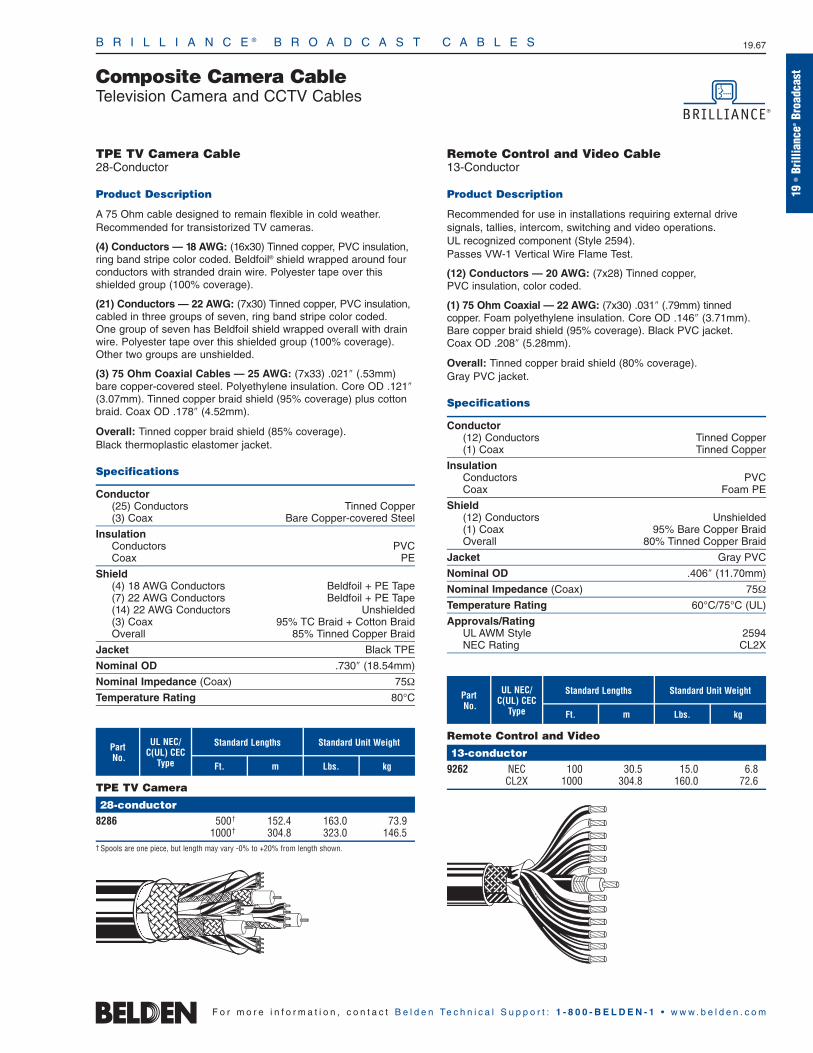
B R I L L I A N C E ® B R O A D C A S T C A B L E S 19.67
19•
Brill
ianc
e®Br
oadc
astComposite Camera Cable
Television Camera and CCTV Cables
F o r m o r e i n f o r m a t i o n , c o n t a c t B e l d e n Te c h n i c a l S u p p o r t : 1 - 8 0 0 - B E L D E N - 1 • w w w . b e l d e n . c o m
Ft.
Standard Lengths
TPE TV Camera Cable28-Conductor
Product Description
A 75 Ohm cable designed to remain flexible in cold weather.Recommended for transistorized TV cameras.
(4) Conductors — 18 AWG: (16x30) Tinned copper, PVC insulation,ring band stripe color coded. Beldfoil® shield wrapped around fourconductors with stranded drain wire. Polyester tape over thisshielded group (100% coverage).
(21) Conductors — 22 AWG: (7x30) Tinned copper, PVC insulation,cabled in three groups of seven, ring band stripe color coded. One group of seven has Beldfoil shield wrapped overall with drainwire. Polyester tape over this shielded group (100% coverage).Other two groups are unshielded.
(3) 75 Ohm Coaxial Cables — 25 AWG: (7x33) .021″ (.53mm) bare copper-covered steel. Polyethylene insulation. Core OD .121″(3.07mm). Tinned copper braid shield (95% coverage) plus cottonbraid. Coax OD .178″ (4.52mm).
Overall: Tinned copper braid shield (85% coverage). Black thermoplastic elastomer jacket.
Specifications
Conductor(25) Conductors Tinned Copper(3) Coax Bare Copper-covered Steel
InsulationConductors PVCCoax PE
Shield(4) 18 AWG Conductors Beldfoil + PE Tape(7) 22 AWG Conductors Beldfoil + PE Tape(14) 22 AWG Conductors Unshielded(3) Coax 95% TC Braid + Cotton BraidOverall 85% Tinned Copper Braid
Jacket Black TPE
Nominal OD .730″ (18.54mm)
Nominal Impedance (Coax) 75Ω
Temperature Rating 80°C
UL NEC/C(UL) CEC
Type
PartNo.
TPE TV Camera
28-conductor8286 500† 152.4 163.0 73.9
1000† 304.8 323.0 146.5† Spools are one piece, but length may vary -0% to +20% from length shown.
m kg
Standard Unit Weight
Lbs.
Ft.
Standard Lengths
Remote Control and Video Cable13-Conductor
Product Description
Recommended for use in installations requiring external drive signals, tallies, intercom, switching and video operations. UL recognized component (Style 2594). Passes VW-1 Vertical Wire Flame Test.
(12) Conductors — 20 AWG: (7x28) Tinned copper, PVC insulation, color coded.
(1) 75 Ohm Coaxial — 22 AWG: (7x30) .031″ (.79mm) tinned copper. Foam polyethylene insulation. Core OD .146″ (3.71mm). Bare copper braid shield (95% coverage). Black PVC jacket. Coax OD .208″ (5.28mm).
Overall: Tinned copper braid shield (80% coverage). Gray PVC jacket.
Specifications
Conductor(12) Conductors Tinned Copper(1) Coax Tinned Copper
InsulationConductors PVCCoax Foam PE
Shield(12) Conductors Unshielded(1) Coax 95% Bare Copper BraidOverall 80% Tinned Copper Braid
Jacket Gray PVC
Nominal OD .406″ (11.70mm)
Nominal Impedance (Coax) 75Ω
Temperature Rating 60°C/75°C (UL)
Approvals/RatingUL AWM Style 2594NEC Rating CL2X
UL NEC/C(UL) CEC
Type
PartNo.
Remote Control and Video
13-conductor9262 NEC 100 30.5 15.0 6.8
CL2X 1000 304.8 160.0 72.6
m kg
Standard Unit Weight
Lbs.

Ft.
Standard Lengths
Audio and Video Composite Cable3 Paired, RG-59U Type
Product Description
Recommended for Electronic News Gathering (ENG) applications.
(3) Pairs — 22 AWG: (7x30) Tinned copper, polypropylene insulation. Nominal insulated conductor OD .046″ (1.17 mm). Individually Beldfoil® shielded with drain wire. PVC jacket, OD .125″(3.20mm). Jacket colors: Brown, Red and Orange. Nominal impedance: 50Ω. Nominal velocity of propagation: 66%. Nominalcapacitance: 32 pF/ft. (105 pF/m)*, 58 pF/ft. (191 pF/m)**.
(2) 75 Ohm Coaxial Cables — 25 AWG: (7x33) .021″ (.53mm) Bare copper. Foam polyethylene insulation. Nominal Core OD .100″(2.54mm). Duofoil® plus tinned copper braid shield (95% coverage).PVC Jacket OD .160″ (4.06mm). Jacket colors: Red and Black.Nominal Impedance: 75Ω. Nominal velocity of propagation: 78%.Nominal capacitance: 17.3 pF/ft. (56.8 pF/m). Nominal attenuationvalue for respective frequencies:
1 MHz .5 db/100 ft. 1.5 db/100m5 MHz 1.1 db/100 ft. 3.6 db/100m
10 MHz 1.5 db/100 ft. 4.9 db/100m50 MHz 3.2 db/100 ft. 10.5 db/100m
100 MHz 4.3 db/100 ft. 14.1 db/100m300 MHz 10.6 db/100 ft. 34.8 db/100m500 MHz 13.8 db/100 ft. 45.3 db/100m
Overall: Matte Black PVC jacket.
Specifications
Conductor(3) Pairs Tinned Copper(2) Coax Bare Copper
InsulationPairs PolypropyleneCoax Foam Polyethylene
Shield(3) 22 AWG Pairs Beldfoil(2) Coax Tinned Copper Braid
Jacket Matte Black PVC
Nominal OD .492″ (12.50mm)
Nominal Impedance (Coax) 75Ω*Capacitance between conductors.
**Capacitance between one conductor and other conductors connected to shield.
UL NEC/C(UL) CEC
Type
PartNo.
Audio and Video Composite Cable
RG-59/U Type • 3 Paired1263B 500 152.4 58.5 26.6
1000 304.8 113.0 51.4
m kg
Standard Unit Weight
Lbs.
Ft.
Standard Lengths
Camera Extension Cable13-Conductor
Product Description
UL Recognized Component (Style 2497). Recommended forremote control, closed circuit and cue line applications. Style 2497 is specified for the Dage 800 and other similar cameras. Passes VW-1 Vertical Wire Flame Test.
(2) Conductors — 20 AWG: (10x30) Tinned copper, PVC insulation,color coded, twisted pair, Mylar® tape wrapped.
(9) Conductors — 22 AWG: (7x30) Tinned copper, PVC insulation.(2) conductors cabled with Beldfoil shield. (2) conductors cabled,unshielded. (5) conductors unshielded.
(2) 75 Ohm Coaxial Cables — 26 AWG: (7x34) .019″ (.48mm) bare copper-covered steel. Foam high-density polyethylene insulation. Core OD .088″ (2.24mm). Tinned copper braid shield(95% coverage). PVC jacket, color coded. Coax OD .142″ (3.61mm).
Overall: Tinned copper braid shield (85% coverage). Chrome PVC jacket.
Specifications
Conductor(11) Conductors Tinned Copper(2) Coax Bare Copper-covered Steel
InsulationConductors PVCCoax Foam PE
Shield(7) Conductors Unshielded(2) Conductors Beldfoil(2) Conductors Mylar Tape(2) Coax 95% Tinned Copper BraidOverall 85% Tinned Copper Braid
Jacket Chrome PVC
Nominal OD .550″ (13.97mm)
Nominal Impedance (Coax) 75Ω
Temperature Rating 60°C
Approvals/RatingUL AWM Style 2497NEC Rating CL2X
UL NEC/C(UL) CEC
Type
PartNo.
Camera Extension Cable
13-conductor9254 NEC 250† 30.5 45.5 20.7
CL2X 1000† 304.8 177.0 80.5†Spools are one piece, but length may vary -0% to +20% from length shown.
m kg
Standard Unit Weight
Lbs.
B R I L L I A N C E ® B R O A D C A S T C A B L E S 19.68
F o r m o r e i n f o r m a t i o n , c o n t a c t B e l d e n Te c h n i c a l S u p p o r t : 1 - 8 0 0 - B E L D E N - 1 • w w w . b e l d e n . c o m
Mylar is a DuPont trademark.
Composite Camera CableTelevision Camera and CCTV Cables

B R I L L I A N C E ® B R O A D C A S T C A B L E S 19.69
19•
Brill
ianc
e®Br
oadc
astRGB Component Video Cable
Bundled RGB Coaxial CablesMiniature and High-Flex Type
F o r m o r e i n f o r m a t i o n , c o n t a c t B e l d e n Te c h n i c a l S u p p o r t : 1 - 8 0 0 - B E L D E N - 1 • w w w . b e l d e n . c o m
Miniature • 30 AWG Stranded (7x38) .012″ TC Conductors • Coax: Duofoil® (100% Cov.) + TC Braid (90% Cov.) • Overall Beldfoil® Shield
Foam HDPE Insulation • Inner PVC Jackets (Color Code: See chart below) • Overall Black PVC JacketUL AWM 1520A NEC: 3 500 152.4 23.0 10.4 30 AWG .056 1.42 Coaxes: .283 7.19 75 78% 17.3 56.7Style 1354 CL2 1000 304.8 50.0 22.7 (7x38) Coax OD: Duofoil(30V 60°C) .012″ .102 2.59 + 90%
TC TC Braid100.0Ω/M′ Overall:328.0Ω/km Beldfoil
9.5Ω/M′31.2Ω/km
1521A NEC: 4 500 152.4 31.0 14.1 same .056 1.42 same .310 7.87CL2 1000 304.8 60.0 27.3 as Coax OD: as
above .102 2.59 above
1522A NEC: 5 500 152.4 34.5 15.6 same .056 1.42 same .338 8.59CL2 1000 304.8 67.0 30.4 as Coax OD: as
above .102 2.59 above
High-Flex • 26 AWG Stranded (7x34) .019″ Bare Copper Conductors • Duofoil (100% Coverage) + TC Braid Shield (93% Coverage)
Foam HDPE Insulation • Inner PVC Jackets (Color Code: See chart below) • Overall Matte Black PVC Jacket60°C 1406B — 3 1000 † 304.8 79.0 35.8 26 AWG .089 2.29 Duofoil .388 9.86 75 78% 17.3 56.7
(7x34) Coax OD: + 93%.019″ .146 3.71 TC Braid
BC 8.6Ω/M′41.5Ω/M′ 28.2Ω/km
136.0Ω/km
1407B — 4 1000 † 304.8 100.0 45.5 same .089 2.29 same .455 11.56as Coax OD: as
above .146 3.71 above
1417B — 5 1000 † 304.8 110.0 49.9 same .089 2.29 same .477 12.12as Coax OD: as
above .146 3.71 above
BC = Bare Copper • DCR = DC Resistance • HDPE = High-density Polyethylene • TC = Tinned Copper
Contact the Belden Customer Service Department for a Comprehensive Connector Cross Reference. 1-800-BELDEN-1. Request quotations of cables not listed.†Spools are one piece, but length may vary ±10% from length shown.
1 .8 2.65 1.5 4.9
10 2.2 7.230 4.0 13.150 5.4 17.7
100 8.2 26.9200 12.5 41.0400 18.9 62.0700 26.5 86.9900 30.8 101.0
1000 32.8 107.6
1 .6 2.05 1.3 4.3
10 1.8 5.930 3.1 10.250 3.9 12.8
100 5.4 17.7200 7.5 24.6400 10.4 34.1700 13.5 44.3900 15.2 49.9
1000 15.9 52.2
Conductor(stranding)DiameterNom. DCR
ShieldingMaterialsNom. DCR
No.of
Cond.
Nom.Imp.(Ω)
Nominal Core OD Nominal OD
Inch mm Inch mm
StandardUnit Weight
Standard Lengths
Lbs. kgFt. m
UL NEC/C(UL) CEC
Type MHz dB/100 Ft.
dB/100m
Nominal Attenuation
Nominal Capacitance
pF/mpF/Ft.
Nom.Vel.of
Prop.
PartNo. dB/
100m
Description
RGB coaxial cables are used for sending red, green and blue signalsthrough separate coaxes in COMPONENT video applications. This type of video transmission provides a sharper, clearer picturethan does the composite video format. COMPONENT video andRGB cabling is ideal for use in graphics, animation and computerdisplay applications.
These bundled coaxial cables are available in 3, 4, 5 and 6 conductor versions and are color coded for easy identification. Cable selection depends on whether the component transmission
is RGB (3 conductor), RGB and Sync (4 conductor), or RGB, Sync and Hold (5 conductor). 6 conductor designs are used for digital audio (AES 3id) and SPDIF (Sony-Phillips Digital Interface)applications, and for specialized component video, multi-channelvideo, or combination applications.
All Belden® RGB cables are pre-timed to less than 5.0 ns/100 ft.delay difference between each coax. This allows for cut-and-connectinstallation with no TDR or Vectorscope timing required.
Color Code Chart
Cond. Color1 Red
2 Green
3 Blue
4 White
5 Yellow
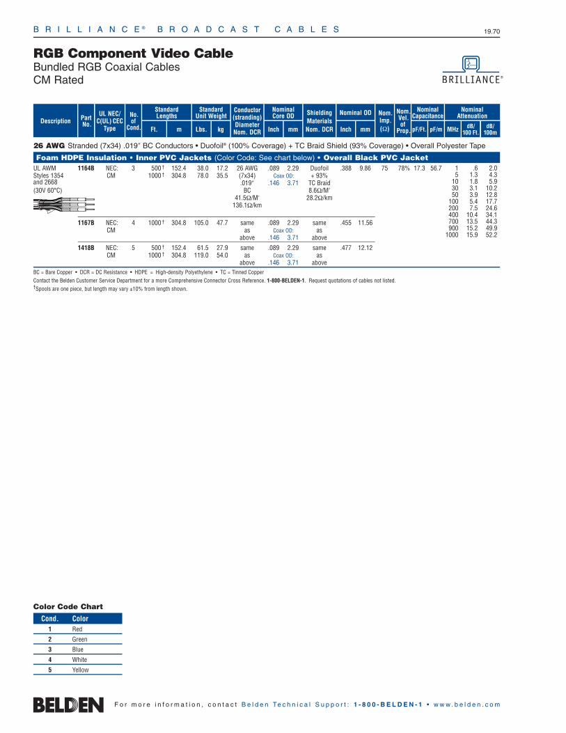
B R I L L I A N C E ® B R O A D C A S T C A B L E S 19.70
F o r m o r e i n f o r m a t i o n , c o n t a c t B e l d e n Te c h n i c a l S u p p o r t : 1 - 8 0 0 - B E L D E N - 1 • w w w . b e l d e n . c o m
26 AWG Stranded (7x34) .019″ BC Conductors • Duofoil® (100% Coverage) + TC Braid Shield (93% Coverage) • Overall Polyester Tape
Foam HDPE Insulation • Inner PVC Jackets (Color Code: See chart below) • Overall Black PVC Jacket UL AWM 1164B NEC: 3 500 † 152.4 38.0 17.2 26 AWG .089 2.29 Duofoil .388 9.86 75 78% 17.3 56.7Styles 1354 CM 1000 † 304.8 78.0 35.5 (7x34) Coax OD: + 93%and 2668 .019″ .146 3.71 TC Braid(30V 60°C) BC 8.6Ω/M′
41.5Ω/M′ 28.2Ω/km. 136.1Ω/km
1167B NEC: 4 1000 † 304.8 105.0 47.7 same .089 2.29 same .455 11.56CM as Coax OD: as
above .146 3.71 above
1418B NEC: 5 500 † 152.4 61.5 27.9 same .089 2.29 same .477 12.12CM 1000 † 304.8 119.0 54.0 as Coax OD: as
above .146 3.71 aboveBC = Bare Copper • DCR = DC Resistance • HDPE = High-density Polyethylene • TC = Tinned CopperContact the Belden Customer Service Department for a more Comprehensive Connector Cross Reference. 1-800-BELDEN-1. Request quotations of cables not listed.†Spools are one piece, but length may vary ±10% from length shown.
1 .6 2.05 1.3 4.3
10 1.8 5.930 3.1 10.250 3.9 12.8
100 5.4 17.7200 7.5 24.6400 10.4 34.1700 13.5 44.3900 15.2 49.9
1000 15.9 52.2
Conductor(stranding)DiameterNom. DCR
ShieldingMaterialsNom. DCR
No.of
Cond.
Nom.Imp.(Ω)
Nominal Core OD Nominal OD
Inch mm Inch mm
StandardUnit Weight
Standard Lengths
Lbs. kgFt. m
UL NEC/C(UL) CEC
Type MHz dB/100 Ft.
dB/100m
Nominal Attenuation
Nominal Capacitance
pF/mpF/Ft.
Nom.Vel.of
Prop.
PartNo. dB/
100m
Description
RGB Component Video CableBundled RGB Coaxial CablesCM Rated
Color Code Chart
Cond. Color1 Red
2 Green
3 Blue
4 White
5 Yellow
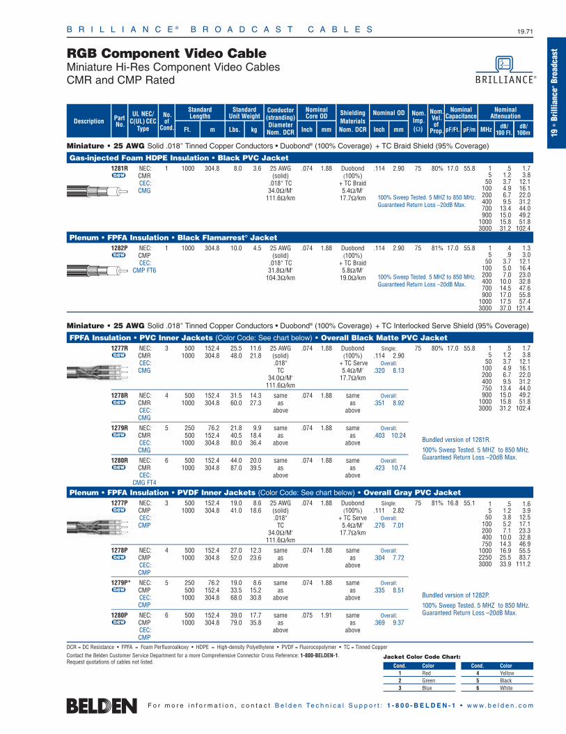
B R I L L I A N C E ® B R O A D C A S T C A B L E S 19.71
19•
Brill
ianc
e®Br
oadc
astRGB Component Video Cable
Miniature Hi-Res Component Video CablesCMR and CMP Rated
F o r m o r e i n f o r m a t i o n , c o n t a c t B e l d e n Te c h n i c a l S u p p o r t : 1 - 8 0 0 - B E L D E N - 1 • w w w . b e l d e n . c o m
Miniature • 25 AWG Solid .018″ Tinned Copper Conductors • Duobond® (100% Coverage) + TC Braid Shield (95% Coverage)
Gas-injected Foam HDPE Insulation • Black PVC Jacket1281R NEC: 1 1000 304.8 8.0 3.6 25 AWG .074 1.88 Duobond .114 2.90 75 80% 17.0 55.8u CMR (solid) (100%)
CEC: .018″ TC + TC BraidCMG 34.0Ω/M′ 5.4Ω/M′
111.6Ω/km 17.7Ω/km
Plenum • FPFA Insulation • Black Flamarrest® Jacket1282P NEC: 1 1000 304.8 10.0 4.5 25 AWG .074 1.88 Duobond .114 2.90 75 81% 17.0 55.8u CMP (solid) (100%)
CEC: .018″ TC + TC Braid CMP FT6 31.8Ω/M′ 5.8Ω/M′
104.3Ω/km 19.0Ω/km
Miniature • 25 AWG Solid .018″ Tinned Copper Conductors • Duobond® (100% Coverage) + TC Interlocked Serve Shield (95% Coverage)
FPFA Insulation • PVC Inner Jackets (Color Code: See chart below) • Overall Black Matte PVC Jacket1277R NEC: 3 500 152.4 25.5 11.6 25 AWG .074 1.88 Duobond Single: 75 80% 17.0 55.8u CMR 1000 304.8 48.0 21.8 (solid) (100%) .114 2.90
CEC: .018″ + TC Serve Overall:CMG TC 5.4Ω/M′ .320 8.13
34.0Ω/M′ 17.7Ω/km111.6Ω/km
1278R NEC: 4 500 152.4 31.5 14.3 same .074 1.88 same Overall:u CMR 1000 304.8 60.0 27.3 as as .351 8.92
CEC: above aboveCMG
1279R NEC: 5 250 76.2 21.8 9.9 same .074 1.88 same Overall:u CMR 500 152.4 40.5 18.4 as as .403 10.24
CEC: 1000 304.8 80.0 36.4 above aboveCMG
1280R NEC: 6 500 152.4 44.0 20.0 same .074 1.88 same Overall:u CMR 1000 304.8 87.0 39.5 as as .423 10.74
CEC: above aboveCMG FT4
Plenum • FPFA Insulation • PVDF Inner Jackets (Color Code: See chart below) • Overall Gray PVC Jacket1277P NEC: 3 500 152.4 19.0 8.6 25 AWG .074 1.88 Duobond Single: 75 81% 16.8 55.1u CMP 1000 304.8 41.0 18.6 (solid) (100%) .111 2.82
CEC: .018″ + TC Serve Overall:CMP TC 5.4Ω/M′ .276 7.01
34.0Ω/M′ 17.7Ω/km111.6Ω/km
1278P NEC: 4 500 152.4 27.0 12.3 same .074 1.88 same Overall:u CMP 1000 304.8 52.0 23.6 as as .304 7.72
CEC: above aboveCMP
1279P* NEC: 5 250 76.2 19.0 8.6 same .074 1.88 same Overall:u CMP 500 152.4 33.5 15.2 as as .335 8.51
CEC: 1000 304.8 68.0 30.8 above aboveCMP
1280P NEC: 6 500 152.4 39.0 17.7 same .075 1.91 same Overall:u CMP 1000 304.8 79.0 35.8 as as .369 9.37
CEC: above aboveCMP
DCR = DC Resistance • FPFA = Foam Perfluoroalkoxy • HDPE = High-density Polyethylene • PVDF = Fluorocopolymer • TC = Tinned CopperContact the Belden Customer Service Department for a more Comprehensive Connector Cross Reference: 1-800-BELDEN-1.Request quotations of cables not listed.
Conductor(stranding)DiameterNom. DCR
ShieldingMaterialsNom. DCR
No.of
Cond.
Nom.Imp.(Ω)
Nominal Core OD Nominal OD
Inch mm Inch mm
StandardUnit Weight
Standard Lengths
Lbs. kgFt. m
UL NEC/C(UL) CEC
Type MHz dB/100 Ft.
dB/100m
Nominal Attenuation
Nominal Capacitance
pF/mpF/Ft.
Nom.Vel.of
Prop.
PartNo. dB/
100m
Description
Bundled version of 1282P.
100% Sweep Tested. 5 MHZ to 850 MHz.Guaranteed Return Loss –20dB Max.
100% Sweep Tested. 5 MHZ to 850 MHz.Guaranteed Return Loss –20dB Max.
1 .5 1.7 5 1.2 3.8
50 3.7 12.1 100 4.9 16.1 200 6.7 22.0 400 9.5 31.2 750 13.4 44.0 900 15.0 49.2
1000 15.8 51.8 3000 31.2 102.4
Bundled version of 1281R.
100% Sweep Tested. 5 MHZ to 850 MHz.Guaranteed Return Loss –20dB Max.
1 .5 1.6 5 1.2 3.9
50 3.8 12.5 100 5.2 17.1 200 7.1 23.3 400 10.0 32.8 750 14.3 46.9
1000 16.9 55.5 2250 25.5 83.7 3000 33.9 111.2
1 .4 1.3 5 .9 3.0
50 3.7 12.1 100 5.0 16.4 200 7.0 23.0 400 10.0 32.8 700 14.5 47.6 900 17.0 55.8
1000 17.5 57.4 3000 37.0 121.4
100% Sweep Tested. 5 MHZ to 850 MHz.Guaranteed Return Loss –20dB Max.
1 .5 1.7 5 1.2 3.8
50 3.7 12.1 100 4.9 16.1 200 6.7 22.0 400 9.5 31.2 700 13.4 44.0 900 15.0 49.2
1000 15.8 51.8 3000 31.2 102.4
Jacket Color Code Chart:
Cond. Color1 Red2 Green3 Blue
Cond. Color4 Yellow5 Black6 White

B R I L L I A N C E ® B R O A D C A S T C A B L E S 19.72
F o r m o r e i n f o r m a t i o n , c o n t a c t B e l d e n Te c h n i c a l S u p p o r t : 1 - 8 0 0 - B E L D E N - 1 • w w w . b e l d e n . c o m
Miniature • 25 AWG Solid .018″ TC Conductors • Duobond® (100% Coverage) + TC Interlocked Serve Shield (95% Coverage)
Gas-injected Foam HDPE Insulation • PVC Jackets (Color Code: See chart below) • Center Spline • No Overall Jacket1281S3 NEC: 3 500 † 152.4 17.0 7.7 25 AWG .074 1.88 Duobond Single: 75 80% 17.0 55.8u CMR 1000 † 304.8 31.0 14.1 (solid) (100%) .114 2.90
CEC: .018″ + TC Serve Overall:CMG TC (95%) .246 6.25
34.0Ω/M′ 5.4Ω/M′111.6Ω/km 17.7Ω/km
1281S4 NEC: 4 500 † 152.4 23.5 10.7 same .074 1.88 same Single:u CMR 1000 † 304.8 44.0 20.0 as as .114 2.90
CEC: above above Overall:CMG .275 6.99
1281S5 NEC: 5* 250 † 76.2 16.0 7.3 same .074 1.88 same Single:u CMR 500 † 152.4 28.5 12.9 as as .114 2.90
CEC: 1000 † 304.8 55.0 25.0 above above Overall:CMG .308 7.82
1281S6 NEC: 6* 500 † 152.4 33.5 15.2 same .074 1.88 same Single:u CMR 1000 † 304.8 68.0 30.8 as as .114 2.90
CEC: above above Overall:CMG FT4 .342 8.69
Plenum • FPFA • Flamarrest® Jackets (Color Code: See chart below) • Center Spline • No Overall Jacket1282S3 NEC: 3 500 152.4 18.5 8.4 25 AWG .075 1.91 Duobond Single: 75 81% 16.8 55.1u CMP 1000 304.8 34.0 15.4 (solid) (100%) .114 2.90
CEC: .018″ + TC Serve Overall:CMP TC (95%) .246 6.25
34.0Ω/M′ 5.4Ω/M′111.6Ω/km 17.7Ω/km
1282S4 NEC: 4 500 152.4 25.5 11.6 same .075 1.91 same Single:u CMP 1000 304.8 49.0 22.2 as as .114 2.90
CEC: above above Overall:CMP .275 6.99
1282S5 NEC: 5* 250 76.2 18.0 8.2 same .075 1.91 same Single:u CMP 500 152.4 33.0 15.0 as as .114 2.90
CEC: 1000 304.8 67.0 30.4 above above Overall:CMP .308 7.82
1282S6 NEC: 6* 500 152.4 39.5 17.9 same .075 1.91 same Single:u CMP 1000 304.8 80.0 36.3 as as .114 2.90
CEC: above above Overall:CMP .342 8.69
DCR = DC Resistance • FPFA = Foam Perfluoroalkoxy • HDPE = High-density Polyethylene • TC = Tinned Copper
Contact the Belden Customer Service Department for a more Comprehensive Connector Cross Reference. 1-800-BELDEN-1. Request quotations of cables not listed.†Spools are one piece, but length may vary ±10% from length shown.*Also available with all Black jackets.
1 .52 1.7 5 1.2 3.8
50 3.7 12.1 100 4.9 16.1 200 6.7 22.0 400 9.5 31.2 750 13.4 44.0 900 15.0 49.2
1000 15.8 51.8 3000 31.2 102.4
1 .50 1.6 5 1.2 3.9
50 3.8 12.1 100 5.2 17.1 200 7.1 23.1 400 10.0 32.9 750 14.3 47.0
1000 16.9 55.4 2250 25.5 83.6 3000 33.9 111.3
100% Sweep tested. 5 MHz to 850 MHz.Guaranteed Return Loss -20db max.
U.S. Patent 7,049,523
100% Sweep tested. 5 MHz to 850 MHz.Guaranteed Return Loss -20db max.
U.S. Patent 7,049,523
Conductor(stranding)DiameterNom. DCR
ShieldingMaterialsNom. DCR
No.of
Cond.
Nom.Imp.(Ω)
Nominal Core OD Nominal OD
Inch mm Inch mm
StandardUnit Weight
Standard Lengths
Lbs. kgFt. m
UL NEC/C(UL) CEC
Type MHz dB/100 Ft.
dB/100m
Nominal Attenuation
Nominal Capacitance
pF/mpF/Ft.
Nom.Vel.of
Prop.
PartNo. dB/
100m
Description
Color Code Chart:
Cond. Color1 Red
2 Green
3 Blue
Cond. Color4 Yellow
5 Black
6 White
RGB Component Video CableBanana Peel® Unjacketed Bundles Mini Hi-Res Component VideoCMR and CMP Rated

B R I L L I A N C E ® B R O A D C A S T C A B L E S 19.73
19•
Brill
ianc
e®Br
oadc
ast
F o r m o r e i n f o r m a t i o n , c o n t a c t B e l d e n Te c h n i c a l S u p p o r t : 1 - 8 0 0 - B E L D E N - 1 • w w w . b e l d e n . c o m
RGB Component Video CableBanana Peel® Unjacketed VideoFLEX® Bundles; RG-59/U TypePlenum Rated
RG-59/U • 20 AWG Solid .032″ Bare Copper Conductors • Duofoil® (100% Coverage) + Tinned Copper Braid Shield (95% Coverage)
Plenum • Foam FEP Insulation • Plenum-Grade PVC Jackets (Color Code: See chart below) • Center Spline • No Overall Jacket300V RMS 1283S3 NEC: 3 250 76.2 26.3 11.9 20 AWG .133 3.38 Duofoil .422 10.72 75 83% 16.2 53.1
u CMP 500 152.4 54.0 24.5 (solid) (95%)CEC: 1000 304.8 103.0 46.7 .032″ + TC BraidCMP BC 3.8Ω/M′
10.0Ω/M′ 12.5Ω/km32.8Ω/km
1283S5 NEC: 5 250 76.2 43.5 19.7 same .133 3.38 same .529 13.44u CMP 500 152.4 88.0 39.9 as as
CEC: 1000 304.8 174.0 78.9 above aboveCMP
1283S6 NEC: 6 250 76.6 59.0 26.8 same .133 3.38 same .588 14.94u CMP 500 152.4 108.0 49.0 as as
CEC: 1000 304.8 209.0 94.8 above aboveCMP
Suitable for Indoor and Outdoor applications.
BC = Bare Copper • DCR = DC Resistance • FEP = Fluorinated Ethylene Propylene • TC = Tinned Copper
Contact the Belden Customer Service Department for a more Comprehensive Connector Cross Reference. 1-800-BELDEN-1. Request quotations of cables not listed.
1 .3 1.0 3.6 .6 2.0 10 .9 2.9
71.5 2.1 6.9135 2.7 8.9 270 3.8 12.5 360 4.4 14.4 540 5.5 18.0 720 6.4 21.0 750 6.5 21.3
1000 7.6 24.9 1500 9.4 30.8 2500 12.4 40.7 3000 13.8 45.3
100% Sweep tested. 5 MHz to 3 GHz.
U.S. Patent 7,049,523
Conductor(stranding)DiameterNom. DCR
ShieldingMaterialsNom. DCR
No.of
Cond.
Nom.Imp.(Ω)
Nominal Core OD Nominal OD
Inch mm Inch mm
StandardUnit Weight
Standard Lengths
Lbs. kgFt. m
UL NEC/C(UL) CEC
Type MHz dB/100 Ft.
dB/100m
Nominal Attenuation
Nominal Capacitance
pF/mpF/Ft.
Nom.Vel.of
Prop.
PartNo. dB/
100m
Description
Color Code Chart:
Cond. Color1 Red
2 Green
3 Blue
Cond. Color4 Yellow
5 Black
6 White

B R I L L I A N C E ® B R O A D C A S T C A B L E S 19.74
F o r m o r e i n f o r m a t i o n , c o n t a c t B e l d e n Te c h n i c a l S u p p o r t : 1 - 8 0 0 - B E L D E N - 1 • w w w . b e l d e n . c o m
Nanoskew™ 24 AWG Solid BC Conductors • Twisted Pairs • Skew 2.2ns/100m nom. • Rip cord • See Color Code Chart (below)
Non-Plenum • Polyolefin Insulation • Maroon PVC Jacket 300V RMS 7987R NEC: 4 U-1000 U-304.8 20.0 9.1 .195 4.95 9.0 100 15.0
u CMR U-1640 U-500.0 32.8 14.9CEC:CMG
Plenum • FEP Insulation • Maroon Flamarrest® PVC Jacket 300V RMS 7987P NEC: 4 U-1000 U-304.8 22.0 10.0 .200 5.08 9.0 100 15.0
u CMP U-1640 U-500.0 36.1 16.4CEC:CMP
Third party verified to TIA/EIA-568-B.2, Category 5e
BC = Bare Copper • DCR = DC Resistance • FEP = Fluorinated Ethylene Propylene • RL = Return Loss • UTP = Unshielded Twisted Pair(s)
*Values provided for information only.
For economy, some system designers seek to use UTP (unshieldedtwisted pair) cable for video applications. However, Digital Videoand Digital Data are processed and viewed differently. Digital Videocontains much more information, requiring more bandwidth thanEthernet data. In addition, video has to be streaming — viewablelive and continuously — whereas data can be sent in packets,resent as necessary, and given time to recompile. Such delays areunacceptable in video. Be cautious, digital signals are not all thesame thing!
Delay Skew should be kept to a minimum for component video and RGB applications for better picture quality and the ability totransmit over longer distances. Delay skew is the difference in thetime of arrival of the components transmitted over different cablecomponents — pairs in the case of UTP. Skew is inherent in allcables, but especially in UTP cables because the pairs are normally
twisted to differing degrees for Ethernet data purposes, specificallyto reduce crosstalk. Obviously picture clarity is lost when the red,green, and blue components arrive out of time with each other, andvarying twist rates cause exactly that to occur.
Cables in this section are NanoSkew, a UTP cable with no Ethernetdata rating (all pairs have the same twist rate), and BrillianceVideoTwist Cat 5e and Cat 6 rated cables with lower, carefully monitored skew relative to standard data cables. Cables designedonly for data applications meet their own skew requirements, butthose are too high for better video transmission, and may be variedby manufacturers without notice. For guaranteed low and consistentskew performance from UTP cables, only NanoSkew or VideoTwistshould be used. The Cat 5e and Cat 6 rated versions are ideal forKVM and blade-edge computer applications.
Rip Cord
Rip Cord
RJ-45 Cables for Audio and Video Applications4-Pair UTP Cables for RGB VideoNanoSkew™ Non-Data and Brilliance VideoTwist® Low-Skew Data Rated Types
Color Codes: DataTwist 5e
Pair No. Color Combination1 White/Blue Stripe & Blue
2 White/Orange Stripe & Orange
3 White/Green Stripe & Green
4 White/Brown Stripe & Brown
PartNo.Description
Nominal OD
Inch mm
Standard Lengths
Ft. m
No.of
Pairs
Standard Unit Wt.
Lbs. kg
UL NEC/C(UL) CEC
Type
Max.DCR(Ω/
100m)
Nom.Imped.
(Ω)
Min.RL(dB)
Freq.(MHz)
Max.Atten.(dB/
100m)
148
10162025
31.2562.5100155200250*350*
2.04.15.86.58.29.3
10.411.717.022.028.132.036.444.8
(same as above)
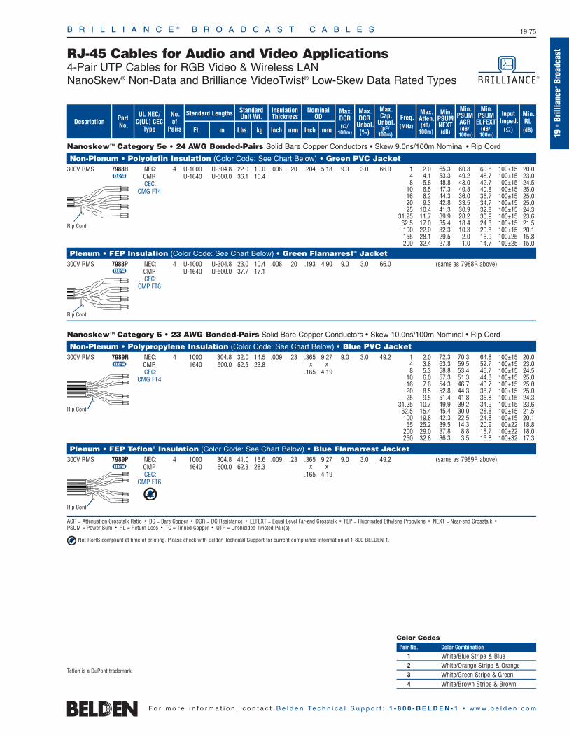
B R I L L I A N C E ® B R O A D C A S T C A B L E S 19.75
19•
Brill
ianc
e®Br
oadc
ast
F o r m o r e i n f o r m a t i o n , c o n t a c t B e l d e n Te c h n i c a l S u p p o r t : 1 - 8 0 0 - B E L D E N - 1 • w w w . b e l d e n . c o m
RJ-45 Cables for Audio and Video Applications4-Pair UTP Cables for RGB Video & Wireless LANNanoSkew® Non-Data and Brilliance VideoTwist® Low-Skew Data Rated Types
Nanoskew™ Category 5e • 24 AWG Bonded-Pairs Solid Bare Copper Conductors • Skew 9.0ns/100m Nominal • Rip Cord
Non-Plenum • Polyolefin Insulation (Color Code: See Chart Below) • Green PVC Jacket300V RMS 7988R NEC: 4 U-1000 U-304.8 22.0 10.0 .008 .20 .204 5.18 9.0 3.0 66.0
u CMR U-1640 U-500.0 36.1 16.4CEC:
CMG FT4
Plenum • FEP Insulation (Color Code: See Chart Below) • Green Flamarrest® Jacket300V RMS 7988P NEC: 4 U-1000 U-304.8 23.0 10.4 .008 .20 .193 4.90 9.0 3.0 66.0
u CMP U-1640 U-500.0 37.7 17.1CEC:
CMP FT6
Nanoskew™ Category 6 • 23 AWG Bonded-Pairs Solid Bare Copper Conductors • Skew 10.0ns/100m Nominal • Rip Cord
Non-Plenum • Polypropylene Insulation (Color Code: See Chart Below) • Blue PVC Jacket 300V RMS 7989R NEC: 4 1000 304.8 32.0 14.5 .009 .23 .365 9.27 9.0 3.0 49.2
u CMR 1640 500.0 52.5 23.8 x xCEC: .165 4.19
CMG FT4
Plenum • FEP Teflon® Insulation (Color Code: See Chart Below) • Blue Flamarrest Jacket300V RMS 7989P NEC: 4 1000 304.8 41.0 18.6 .009 .23 .365 9.27 9.0 3.0 49.2
u CMP 1640 500.0 62.3 28.3 x xCEC: .165 4.19
CMP FT6
ACR = Attenuation Crosstalk Ratio • BC = Bare Copper • DCR = DC Resistance • ELFEXT = Equal Level Far-end Crosstalk • FEP = Fluorinated Ethylene Propylene • NEXT = Near-end Crosstalk •PSUM = Power Sum • RL = Return Loss • TC = Tinned Copper • UTP = Unshielded Twisted Pair(s)
Not RoHS compliant at time of printing. Please check with Belden Technical Support for current compliance information at 1-800-BELDEN-1.
Rip Cord
Rip Cord
Rip Cord
PartNo.Description
Nominal OD
Inch mm
Standard Lengths
Ft. m
No.of
Pairs
StandardUnit Wt.
InsulationThickness
Lbs. kg Inch mm
UL NEC/C(UL) CEC
Type
Max.DCR(Ω/
100m)
Max.DCR
Unbal.(%)
Max.Cap.
Unbal.(pF/
100m)
Freq.(MHz)
Max.Atten.(dB/
100m)
Min.PSUMNEXT(dB)
Min.PSUMACR(dB/100m)
Min.PSUM
ELFEXT(dB/100m)
InputImped.
(Ω)
Min.RL(dB)
65.353.348.847.344.342.841.339.935.432.329.527.8
60.349.243.040.836.033.530.928.218.410.32.01.0
100±15100±15100±15100±15100±15100±15100±15100±15100±15100±15100±25100±25
148
10162025
31.2562.5100155200
2.04.15.86.58.29.3
10.411.717.022.028.132.4
(same as 7988R above)
20.023.024.525.025.025.024.323.621.520.115.815.0
60.848.742.740.836.734.732.830.924.820.816.914.7
(same as 7989R above)
Rip Cord
72.363.358.857.354.352.851.449.945.442.339.537.836.3
70.359.553.451.346.744.341.839.230.022.514.38.83.5
64.852.746.744.840.738.736.834.928.824.820.918.716.8
20.023.024.525.025.025.024.323.621.520.118.818.017.3
100±15100±15100±15100±15100±15100±15100±15100±15100±15100±15100±22100±22100±32
148
10162025
31.2562.5100155200250
2.03.85.36.07.68.59.5
10.715.419.825.229.032.8
Color CodesPair No. Color Combination
1 White/Blue Stripe & Blue2 White/Orange Stripe & Orange3 White/Green Stripe & Green4 White/Brown Stripe & Brown
Teflon is a DuPont trademark.

B R I L L I A N C E ® B R O A D C A S T C A B L E S 19.76
F o r m o r e i n f o r m a t i o n , c o n t a c t B e l d e n Te c h n i c a l S u p p o r t : 1 - 8 0 0 - B E L D E N - 1 • w w w . b e l d e n . c o m
RJ-45 Cables for Audio and Video Applications4-Pair ScTP Cat 5e Indoor/Outdoor for Wireless LAN andHigh-Flex and Rugged Cat 5e Patch Cable
Wireless LAN • 24 AWG Solid BC Conductors • Twisted Pairs • Overall Beldfoil Shield (100% Coverage) • Stranded TC Drain Wire
Non-Plenum • Polyolefin Insulation (Color Code: See Chart Below) • Oil- and Sun-Resistant Black PVC Jacket 300V RMS 1300A NEC: 4 500 152.4 18.5 8.4 .010 .25 .265 6.73 9.3 3.0 330
u CMR, CMX 1000 304.8 34.0 15.4CEC:
CMG FT4
Shield bonded to jacket. Jacket sequentially marked at 2 ft. intervals.
Non-Plenum • Polypropylene Insulation (Color Code: See Chart Below) • Black Low-Smoke, Zero-Halogen Jacket 300V RMS 1300SB NEC: 4 1000 304.8 35.0 15.9 .010 .25 .260 6.60 9.3 3.0 330
u CMG-LSCEC:
CMG-LS FT4Limited Smoke
LSZH and ABS Type ApprovedJacket sequentially marked at 2 ft. intervals.
Hi-Flex Patch • 24 AWG Bonded Pairs Stranded (7x32) Bare Copper Conductors
Non-Plenum • Polyolefin Insulation (Color Code: See Chart Below) • Black Industrial-Grade PVC Jacket 300V RMS 1304A 4 500 152.4 14.5 6.6 .009 .22 .245 6.22 9.0 3.0 66
u 1000 304.8 28.0 12.7
Jacket sequentially marked at 2 ft. intervals.
Non-Plenum • Polyolefin Insulation (Color Code: See Chart Below) • PVC Inner Jacket • Matte Black PVC Outer Jacket 300V RMS 1305A 4 500 152.4 23.0 10.4 .009 .22 .295 7.49 9.0 3.0 66
u 1000 304.8 42.0 19.1
Jacket sequentially marked at 2 ft. intervals.
ACR = Attenuation Crosstalk Ratio • BC = Bare Copper • DCR = DC Resistance • ELFEXT = Equal Level Far-end Crosstalk • FEP = Fluorinated Ethylene Propylene • NEXT = Near-end Crosstalk •PSUM = Power Sum • RL = Return Loss • TC = Tinned Copper • UTP = Unshielded Twisted Pair(s)
PartNo.Description
Nominal OD
Inch mm
Standard Lengths
Ft. m
No.of
Pairs
StandardUnit Wt.
InsulationThickness
Lbs. kg Inch mm
UL NEC/C(UL) CEC
Type
Max.DCR(Ω/
100m)
Max.DCR
Unbal.(%)
Max.Cap.
Unbal.(pF/
100m)
Freq.(MHz)
Max.Atten.(dB/
100m)
Min.PSUMNEXT(dB)
Min.PSUMACR(dB/100m)
Min.PSUM
ELFEXT(dB/100m)
InputImped.
(Ω)
Min.RL(dB)
62.353.348.847.344.342.841.339.935.432.3
60.049.043.041.036.033.530.928.019.011.0
60.848.742.740.836.734.732.830.924.820.8
20.023.024.525.025.025.024.323.621.520.1
100±15100±15100±15100±15100±15100±15100±15100±15100±15100±15
148
10162025
31.2562.5100
2.04.15.86.58.29.3
10.411.717.022.0
65.356.351.850.347.345.844.342.938.435.328.227.2
62.951.545.042.637.534.831.929.018.39.2——
60.848.742.740.836.734.732.830.924.820.811.29.9
20.023.024.525.025.025.024.323.621.520.118.017.0
100±12100±12100±12100±12100±12100±12100±15100±15100±15100±18100±20100±22
148
10162025
31.2562.5100300350
2.44.86.87.79.7
11.012.413.920.226.048.653.2
62.353.348.847.344.342.841.339.935.432.3
60.349.243.040.836.133.530.928.218.410.3
60.848.742.740.836.734.732.830.924.820.8
20.023.024.525.025.025.024.323.621.520.1
100±15100±15100±15100±15100±15100±15100±15100±15100±15100±15
148
10162025
31.2562.5100
2.04.15.86.58.29.3
10.411.717.022.0
Color CodesPair No. Color Combination
1 White/Blue Stripe & Blue2 White/Orange Stripe & Orange3 White/Green Stripe & Green4 White/Brown Stripe & Brown
Rip Cord
Drain Wire
Drain Wire
Teflon is a DuPont trademark.
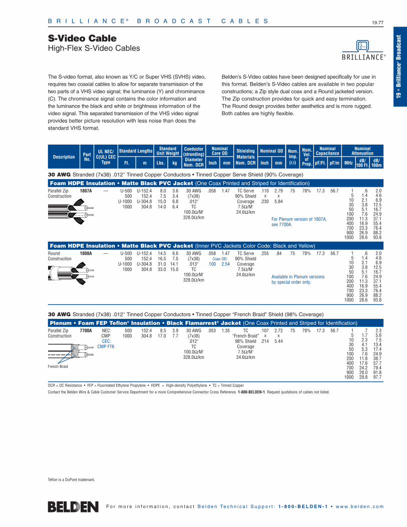
B R I L L I A N C E ® B R O A D C A S T C A B L E S 19.77
19•
Brill
ianc
e®Br
oadc
ast
F o r m o r e i n f o r m a t i o n , c o n t a c t B e l d e n Te c h n i c a l S u p p o r t : 1 - 8 0 0 - B E L D E N - 1 • w w w . b e l d e n . c o m
S-Video CableHigh-Flex S-Video Cables
30 AWG Stranded (7x38) .012″ Tinned Copper Conductors • Tinned Copper Serve Shield (90% Coverage)
Foam HDPE Insulation • Matte Black PVC Jacket (One Coax Printed and Striped for Identification)Parallel Zip 1807A — U-500 U-152.4 8.0 3.6 30 AWG .058 1.47 TC Serve .110 2.79 75 78% 17.3 56.7Construction 500 152.4 7.5 3.4 (7x38) 90% Shield x x
U-1000 U-304.8 15.0 6.8 .012″ Coverage .230 5.841000 304.8 14.0 6.4 TC 7.5Ω/M′
100.0Ω/M′ 24.6Ω/km328.0Ω/km
Foam HDPE Insulation • Matte Black PVC Jacket (Inner PVC Jackets Color Code: Black and Yellow)Round 1808A — U-500 U-152.4 14.5 6.6 30 AWG .058 1.47 TC Serve .255 .84 75 78% 17.3 56.7Construction 500 152.4 16.5 7.5 (7x38) Coax OD: 90% Shield
U-1000 U-304.8 31.0 14.1 .013″ .100 2.54 Coverage1000 304.8 33.0 15.0 TC 7.5Ω/M′
100.0Ω/M′ 24.6Ω/km328.0Ω/km
30 AWG Stranded (7x38) .012″ Tinned Copper Conductors • Tinned Copper “French Braid” Shield (98% Coverage)
Plenum • Foam FEP Teflon® Insulation • Black Flamarrest® Jacket (One Coax Printed and Striped for Identification)Parallel Zip 7700A NEC: 500 152.4 8.5 3.9 30 AWG .053 1.35 TC .107 2.72 75 78% 17.3 56.7Construction CMP 1000 304.8 17.0 7.7 (7x38) “French Braid” x x
CEC: .012″ 98% Shield .214 5.44CMP FT6 TC Coverage
100.0Ω/M′ 7.5Ω/M′328.0Ω/km 24.6Ω/km
DCR = DC Resistance • FEP = Fluorinated Ethylene Propylene • HDPE = High-density Polyethylene • TC = Tinned Copper
Contact the Belden Wire & Cable Customer Service Department for a more Comprehensive Connector Cross Reference. 1-800-BELDEN-1. Request quotations of cables not listed.
Available in Plenum versions by special order only.
For Plenum version of 1807A,see 7700A.
1 .6 2.05 1.4 4.6
10 2.1 6.930 3.8 12.550 5.1 16.7
100 7.6 24.9200 11.3 37.1400 16.9 55.4700 23.3 76.4900 26.9 88.2
1000 28.6 93.8
1 .6 2.05 1.4 4.6
10 2.1 6.930 3.8 12.550 5.1 16.7
100 7.6 24.9200 11.3 37.1400 16.9 55.4700 23.3 76.4900 26.9 88.2
1000 28.6 93.8
1 .7 2.35 1.7 5.6
10 2.3 7.530 4.1 13.450 5.3 17.4
100 7.6 24.9200 11.8 38.7400 17.6 57.7700 24.2 79.4900 28.0 91.8
1000 29.8 97.7
French Braid
ShieldingMaterialsNom. DCR
Nom.Imp.(Ω)
Nominal Core OD Nominal OD
Inch mm Inch mm
Conductor(stranding)DiameterNom. DCR
StandardUnit WeightStandard Lengths
Lbs. kgFt. m
UL NEC/C(UL) CEC
Type
PartNo.
MHz dB/100 Ft.
dB/100m
Nominal Attenuation
Nominal Capacitance
pF/mpF/Ft.
Nom.Vel.of
Prop.Description
The S-video format, also known as Y/C or Super VHS (SVHS) video,requires two coaxial cables to allow for separate transmission of thetwo parts of a VHS video signal; the luminance (Y) and chrominance(C). The chrominance signal contains the color information and the luminance the black and white or brightness information of thevideo signal. This separated transmission of the VHS video signal provides better picture resolution with less noise than does the standard VHS format.
Belden’s S-Video cables have been designed specifically for use in this format. Belden’s S-Video cables are available in two popular constructions; a Zip style dual coax and a Round jacketed version.The Zip construction provides for quick and easy termination. The Round design provides better aesthetics and is more rugged.Both cables are highly flexible.
Teflon is a DuPont trademark.
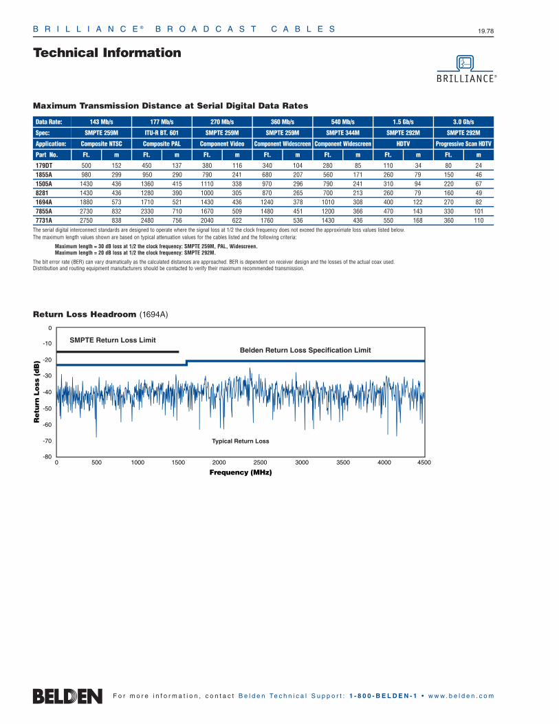
B R I L L I A N C E ® B R O A D C A S T C A B L E S 19.78
Technical Information
F o r m o r e i n f o r m a t i o n , c o n t a c t B e l d e n Te c h n i c a l S u p p o r t : 1 - 8 0 0 - B E L D E N - 1 • w w w . b e l d e n . c o m
Return Loss Headroom (1694A)
0
-10
-20
-30
-40
-50
-70
-60
-80
Retu
rn L
oss
(dB
)
Frequency (MHz)0 500 1000 1500 2000 2500 3000 3500 4000 4500
SMPTE Return Loss LimitBelden Return Loss Specification Limit
Typical Return Loss
Maximum Transmission Distance at Serial Digital Data Rates
179DT 500 152 450 137 380 116 340 104 280 85 110 34 80 241855A 980 299 950 290 790 241 680 207 560 171 260 79 150 461505A 1430 436 1360 415 1110 338 970 296 790 241 310 94 220 678281 1430 436 1280 390 1000 305 870 265 700 213 260 79 160 491694A 1880 573 1710 521 1430 436 1240 378 1010 308 400 122 270 827855A 2730 832 2330 710 1670 509 1480 451 1200 366 470 143 330 1017731A 2750 838 2480 756 2040 622 1760 536 1430 436 550 168 360 110
The serial digital interconnect standards are designed to operate where the signal loss at 1/2 the clock frequency does not exceed the approximate loss values listed below. The maximum length values shown are based on typical attenuation values for the cables listed and the following criteria:
Maximum length = 30 dB loss at 1/2 the clock frequency: SMPTE 259M, PAL, Widescreen.Maximum length = 20 dB loss at 1/2 the clock frequency: SMPTE 292M.
The bit error rate (BER) can vary dramatically as the calculated distances are approached. BER is dependent on receiver design and the losses of the actual coax used. Distribution and routing equipment manufacturers should be contacted to verify their maximum recommended transmission.
Data Rate: 143 Mb/s
SMPTE 259M
Composite NTSC
Ft. m
177 Mb/s 270 Mb/s 360 Mb/s 540 Mb/s 1.5 Gb/s
Spec:
Application:
Part No.
ITU-R BT. 601
Composite PAL
Ft. m
SMPTE 259M
Component Video
Ft. m
SMPTE 259M
Component Widescreen
Ft. m
SMPTE 344M
Component Widescreen
Ft. m
SMPTE 292M
HDTV
Ft. m
3.0 Gb/s
SMPTE 292M
Progressive Scan HDTV
Ft. m
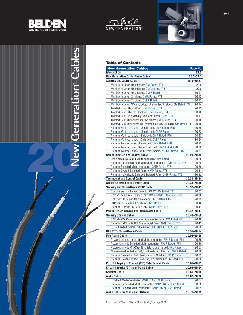
20
Please refer to “Terms of Use of Master Catalog” on page 22.22
New
Gen
erat
ion
®Cab
les
20.1
Table of ContentsNew Generation Cables Page No.
Introduction 20.2New Generation Cable Finder Guide 20.3–20.7Security and Alarm Cable 20.8–20.27
Multi-conductor, Unshielded: CM Rated, FT1 20.8Multi-conductor, Unshielded: CMR Rated, FT4 20.9Multi-conductor, Unshielded: CL3R Rated 20.11Multi-conductor, Shielded: CMR Rated, FT4 20.12Multi-conductor, Shielded: CL3R Rated 20.13Multi-conductor, Water-blocked, Unshielded/Shielded: CM Rated, FT1 20.14Twisted Pairs, Unshielded: CMR Rated, FT4 20.15Twisted Pairs, Overall Shielded: CMR Rated, FT4 20.16Twisted Pairs, Individually Shielded: CMR Rated, FT4 20.17Twisted Pairs+Conductor(s), Shielded: CMR Rated, FT4 20.18Twisted Pairs+Conductor(s), Water-blocked, Shielded: CM Rated, FT1 20.19Plenum Multi-conductor, Unshielded: CMP Rated, FT6 20.20Plenum Multi-conductor, Unshielded: CL2P Rated 20.22Plenum Multi-conductor, Shielded: CMP Rated, FT6 20.23Plenum Multi-conductor, Shielded: CL2P Rated 20.24Plenum Twisted Pairs, Unshielded: CMP Rated, FT6 20.25Plenum Twisted Pairs, Overall Shielded: CMP Rated, FT6 20.26Plenum Twisted Pairs+Conductors, Shielded: CMP Rated, FT6 20.27
Communication and Control Cable 20.28–20.32Unshielded Pairs and Multi-conductor: CM Rated 20.28Plenum Unshielded Pairs and Multi-conductor: CMP Rated, FT6 20.29Plenum Shielded Multi-conductor: CMP Rated, FT6 20.30Plenum Overall Shielded Pairs: CMP Rated, FT6 20.31Plenum Individually Shielded Twisted Pairs: CMP Rated, FT6 20.32
Thermostat and Control Cable 20.33–20.34Access Control Banana Peel® Cable 20.35–20.36Security and Surveillance CCTV Cable 20.37–20.41
Coax or Water-blocked Coax for CCTV: CM Rated, FT1 20.37Composite Coax + Twisted Pair: CM or CMP (Plenum) Rated 20.38Coax for CCTV and Card Readers: CMP Rated, FT6 20.39UTP for CCTV and PTZ: CM or CMR Rated 20.40Plenum UTP for CCTV and PTZ: CMP Rated, FT6 20.41
Pan/Tilt/Zoom Banana Peel Composite Cable 20.42–20.47Security Coaxial Cable 20.48–20.50
CATV/MATV, Commercial or Schlage Systems: CM Rated, FT1 20.48Plenum CATV or MATV Commercial Coax: CMP Rated, FT6 20.49CCTV Limited Combustible Coax: CMP Rated, FHC 25/50 20.50
UTP CCTV Surveillance Cable 20.51–20.54Fire Alarm Cable 20.55–20.60
Power-Limited, Unshielded Multi-conductor: FPLR Rated, FT4 20.55Power-Limited, Shielded Multi-conductor: FPLR Rated, FT4 20.56Power-Limited, Mid-Cap, Unshielded or Shielded: FPL Rated 20.57Non-Power-Limited Signal, Unshielded or Shielded: NPLF Rated 20.58Plenum Power-Limited, Unshielded or Shielded: FPLP Rated 20.59Plenum Power-Limited, Mid-Cap, Unshielded or Shielded: FPLP 20.60
Circuit Integrity In Conduit (CIC) Safe-T-Line® Cable 20.61–20.62Circuit Integrity (CI) Safe-T-Line Cable 20.63–20.64Speaker Cable 20.65–20.66Audio Cable 20.67–20.70
Shielded Multi-conductor: CMR FT4 or CL3R Rated 20.67Plenum Unshielded Multi-conductor: CMP FT6 or CL2P Rated 20.68Plenum Shielded Multi-conductor: CMP FT6 or CL2P Rated 20.69
Audio Cable for Nurse Call Stations 20.71–20.72
N E W G E N E R A T I O N ® C A B L E S 20.2
Sound, Security and Alarm CablesIntroduction
Market needs are continually challengingthe limits of cable technology. And nowhereis the demand for uncompromising qualityand leading-edge technology more criticalthan in sound and security applications.
Belden’s answer to this challenge is a line of low voltage, electronic cables that provide the selection, imagination,technical expertise and quality required to meet the demands of increasingly complex sound and security systems. We call this line New Generation.
Unmatched Selection, Quality And Service
Our New Generation cable line includesone of the largest, most economical, and up-to-date selections of reliable multi-conductor and coaxial products on the market today. A full complement of cables for sound, control, computer interconnect, alarm, security, CCTV and other security applications is offered.And behind every one of these cables isyears of research and development andBelden’s unequaled reputation for qualityand service.
Most of our New Generation cables areavailable from stock. Many of these areavailable off the shelf from distributors. If you have a new or unusual application or you cannot find a New Generation cablein this catalog section that meets your technical requirements, contact TechnicalSupport at 1-800-BELDEN-1.
Innovative and Advanced Cables
For over 90 years, Belden has been committed to the development and supportof highly effective cabling solutions. WithBelden® New Generation cable products,you can be assured that you’re getting themost innovative and advanced cables available today. Here are a few examplesof our commitment to making our cables not only work better but also better to work with:
Sequential footage markings on the cable jacket quickly eliminate guesswork and waste.
The cables are predominantly NEC Riser Rated (CMR and FPLR) or above to meet even unusually stringent application conditions. All Belden CM, CMR and CMP types are both UL and C(UL) approved.
A rip cord underneath the jacket providesfor easy removal at installation.
Easy set-up and easy-pulling, space-saving, tangle-free coil packages available for many codes.These revolutionary coil packages vastly reduce job clean-up and waste removal as well.
Water-blocked options for multi-conductorcables and for coax — where security, surveillance and fire alarm cables are installed in intermittently wet environments.
Our Banana Peel® Composite Cablesare designed for easier and fasterinstallation than traditional compositecables. They offer no overall jacketwhich eliminates the stripping of thejacket, individual cable components thatare all instantly identifiable, a smallerOD, breakout versatility, prevention ofshort circuits caused by contact with the center conductor while stripping the outer jacket, and color-coded individual cables by application for easy identification.
Our New Generation Safe-T-Line®
Cables for Circuit Integrity meet Article760 of the National Electrical Code forFire-Alarm Circuit Integrity (CI) cable,the National Fire Alarm Code (NFPA 72)requirements for survivability; ULStandard 1424 — Cables for Power-limited Fire Alarm Circuits, and ULStandard 2196 — Circuit Integrity Two-hour Flame Test.
Quality You Can Count On
A system failure, or loss of continuity, canbe catastrophic. That’s why you need acable that is recognized the world over forits quality. And that cable is a Belden cable.All of our New Generation cables aredesigned with quality as a top priority.Belden was the first major designer andmanufacturer of electronic wire and cableproducts to earn ISO 9001:2000 registrationfor all its domestic and overseas facilities.In achieving total ISO 9001:2000 registration;United States’ Belden passed some of
the United States’ and Europe’s most rigorous tests for quality and, once again,demonstrated the company’s dedication to total quality.
New GenerationCable Packaging
UnReel® Dispenser
As with most Belden cables, several NewGeneration cable products are available in Belden’s UnReel cardboard dispenser.The UnReel is a unique packaging dispensing system developed by Belden to save time and labor compared to spools, and eliminate the need for dereeling equipment. Lightweight and more economical than conventional drums or reels, UnReel dispensers have pre-punched handles for easy, individualtransport as well as rectangular boxes foreasy pallet delivery and storage. UnReelcable pays out smoothly and evenly with less kinking, twisting or backlashing. It also rolls out 60% faster than cable from spools or reels.
Revolutionary Coil Package
New this year, certain New Generationcables are available in a coil package.These revolutionary coils are an easy-to-handle standard package size so palletloading is uniform. In addition, this densely packaged coil results in less space requirements for your wire, savingshelf space, truck space and cage space at the job. Plus, with no box and no spool,there is far less waste and clean-uprequired after the job.
Coils are the most tangle-proof packageavailable. And, because the wire pulls fromthe middle you only have to pull the weightof the length of wire that is your distancefrom the coil. In pulling spools, you arealways pulling the whole package weight toget it spinning. And with spools, when youstop pulling, the spool doesn’t stop spinning.Help is required to stop this from happeningand to keep the payouts tangle free. Withcoils, that help can be doing somethingmore productive. What’s more, five coilsmay be stacked and pulled in parallelthrough their common center.
So ask for New Generation’s coil package,and leave reel jacks and payout standsbehind along with any worries about wetboxes or discarding of empty boxes.
F o r m o r e i n f o r m a t i o n , c o n t a c t B e l d e n Te c h n i c a l S u p p o r t : 1 - 8 0 0 - B E L D E N - 1 • w w w . b e l d e n . c o m

N E W G E N E R A T I O N ® C A B L E S 20.3
Sound, Security and Alarm CablesCable Finder Guide — By ConstructionPaired and Multiconductor
20•
New
Gene
ratio
n®Ca
bles
F o r m o r e i n f o r m a t i o n , c o n t a c t B e l d e n Te c h n i c a l S u p p o r t : 1 - 8 0 0 - B E L D E N - 1 • w w w . b e l d e n . c o m
Stranding
No. of Cond.
or Pairs Part No. Rating Page No.
Non-Shielded
Non-Plenum Plenum
Part No. Rating Page No. Part No. Rating Page No. Part No. Rating Page No.
Shielded
Non-Plenum PlenumAWGSize
Paired18 2 PR 7 5341UE CMR 20.15 6341UE CMP 20.25 5341FE CMR 20.16 — — —
3 PR 7 5342UE CMR 20.15 6342UE CMP 20.25 5342FE CMR 20.16 6342FE CMP 20.264 PR 7 5343UE CMR 20.15 6343UE CMP 20.25 5343FE CMR 20.16 6343FE CMP 20.266 PR 7 5345UE CMR 20.15 6345UE CMP 20.25 5345FE CMR 20.16 6345FE CMP 20.269 PR 7 5347UE CMR 20.15 6347UE CMP 20.25 — — — 6347FE CMP 20.26
20 2 PR 7 — — — — — — 5441FE CMR 20.16 6441FE CMP 20.263 PR 7 — — — — — — 5442FE CMR 20.16 — — —4 PR 7 — — — — — — — — — 6443FE CMP 20.266 PR 7 — — — — — — 5445FE CMR 20.16 — — —
22 2 PR Solid — — — 6561UE CMP 20.25 5561FE CMR 20.16 6561FE CMP 20.262 PR 7 5541UE CMR 20.15 6541UE CMP 20.25 5541FE CMR 20.16 6541FE CMP 20.263 PR Solid — — — — — — 5562FE CMR 20.16 — — —3 PR 7 5542UE CMR 20.15 6542UE CMP 20.25 5542FE CMR 20.16 6542FE CMP 20.264 PR Solid — — — — — — 5563FE CMR 20.16 — — —4 PR 7 5543UE CMR 20.15 6543UE CMP 20.25 5543FE CMR 20.16 6543FE CMP 20.266 PR 7 — — — 6545UE CMP 20.25 5545FE CMR 20.16 6545FE CMP 20.269 PR 7 5547UE CMR 20.15 6547UE CMP 20.25 — — — 6547FE CMP 20.26
Shielded Twisted Pairs22 4 STP 7 — — — — — — 5543PE CMR 20.17 — — —
Combination Pairs + Conductors18 1STP 7 — — — — — — 5302GE CMR 20.18 — — —
+2/C20 1STP 7 — — — — — — 5401GE CMR 20.18 6401GE CMP 20.27
+1/C1STP 7 — — — — — — 5402GE CMR 20.18 — — —+2/C
22 1STP 7 — — — — — — 5501GE CMR 20.18 6501GE CMP 20.27+1/C1STP 7 — — — — — — 5502GE CMR 20.18 6502GE CMP 20.27+2/C1STP 7 — — — — — — 5542GE CMR 20.18 — — —+2TP
Water-blocked18 2/C 7 5300U1 CM 20.14 — — — 5300F1 CM 20.14 — — —20 2/C 7 — — — — — — 5400F1 CM 20.14 — — —22 2/C 7 — — — — — — 5500F1 CM 20.14 — — —
1STP Solid — — — — — — 5521G1 CM 20.19 — — —+1/C1STP 7 — — — — — — 5501G1 CM 20.19 — — —+1/C1STP Solid — — — — — — 5522G1 CM 20.19 — — —+2/C1STP 7 — — — — — — 5502G1 CM 20.19 — — —+2/C1STP 7 — — — — — — 5504G1 CM 20.19 — — —+4/C
STP = Shielded Twisted Pair(s) • TP = Twisted Pair(s) • PR = Pair(s) • /C = Conductor(s)
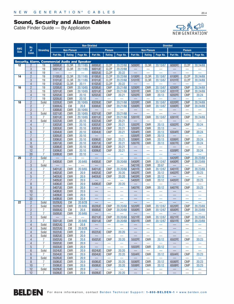
N E W G E N E R A T I O N ® C A B L E S 20.4
F o r m o r e i n f o r m a t i o n , c o n t a c t B e l d e n Te c h n i c a l S u p p o r t : 1 - 8 0 0 - B E L D E N - 1 • w w w . b e l d e n . c o m
Sound, Security and Alarm CablesCable Finder Guide — By Application
StrandingNo. of
Cond.Part No. Rating Page No.
Non-Shielded
Non-Plenum Plenum
Part No. Rating Page No. Part No. Rating Page No. Part No. Rating Page No.
Shielded
Non-Plenum PlenumAWGSize
Security, Alarm, Commercial Audio and Speaker12 2 19 5000UE CL3R 20.11/65 6000UE CL2P 20.22/68 5000FE CL3R 20.13/67 6000FE CL2P 20.24/69
3 19 5001UE CL3R 20.11/65 6001UE CL2P 20.22/68 — — — — — —4 19 — — — 6002UE CL2P 20.22 — — — — — —
14 2 19 5100UE CL3R 20.11/65 6100UE CL2P 20.22/68 5100FE CL3R 20.13/67 6100FE CL2P 20.24/693 19 5101UE CL3R 20.11/65 6101UE CL2P 20.22/68 5101FE CL3R 20.13/67 6101FE CL2P 20.24/694 19 5102UE CL3R 20.11 6102UE CL2P 20.22 — — — — — —
16 2 19 5200UE CMR 20.10/65 6200UE CMP 20.21/68 5200FE CMR 20.13/67 6200FE CMP 20.24/693 19 5201UE CMR 20.10/65 6201UE CMP 20.21/68 5201FE CMR 20.13/67 6201FE CMP 20.24/694 19 5202UE CMR 20.10 6202UE CMP 20.21 5202FE CMR 20.13 6202FE CMP 20.247 19 5205UE CMR 20.10 — — — — — — — — —
18 2 Solid 5320UE CMR 20.10/65 6320UE CMP 20.21/68 5320FE CMR 20.13/67 6320FE CMP 20.24/692 7 5300UG CM 20.8 6300UE CMP 20.21/68 5300FE CMR 20.13/67 6300FE CMP 20.24/692 7 5300UE CMR 20.10/65 — — — — — — — — —3 Solid 5321UE CMR 20.10/65 6321UE CMP 20.21/68 — — — — — —3 7 5301UE CMR 20.10/65 6301UE CMP 20.21/68 5301FE CMR 20.13/67 6301FE CMP 20.24/694 Solid 5322UE CMR 20.10 6322UE CMP 20.21 — — — — — —4 7 5302UE CMR 20.10 6302UE CMP 20.21 5302FE CMR 20.13 6302FE CMP 20.245 7 5303UE CMR 20.10 6303UE CMP 20.21 5303FE CMR 20.13 — — —6 7 5304UE CMR 20.10 6304UE CMP 20.21 5304FE CMR 20.13 6304FE CMP 20.247 7 5305UE CMR 20.10 — — — 5305FE CMR 20.13 — — —8 7 5306UE CMR 20.10 6306UE CMP 20.21 5306FE CMR 20.13 6306FE CMP 20.249 7 5307UE CMR 20.10 6307UE CMP 20.21 5307FE CMR 20.13 6307FE CMP 20.2410 7 5308UE CMR 20.10 6308UE CMP 20.21 — — — — — —12 7 5309UE CMR 20.10 6309UE CMP 20.21 — — — 6309FE CMP 20.2420 7 530BUE CMR 20.10 — — — — — — — — —
20 2 Solid — — — — — — — — — 6420FE CMP 20.23/692 7 5400UE CMR 20.9/65 6400UE CMP 20.20/68 5400FE CMR 20.12/67 6400FE CMP 20.23/693 Solid — — — — — — 5421FE CMR 20.67 — — —3 7 5401UE CMR 20.9/65 6401UE CMP 20.20/68 5401FE CMR 20.12/67 6401FE CMP 20.23/694 7 5402UE CMR 20.9 6402UE CMP 20.20 5402FE CMR 20.12 6402FE CMP 20.235 7 5403UE CMR 20.9 6403UE CMP 20.20 5403FE CMR 20.12 — — —7 7 5405UE CMR 20.9 — — — 5405FE CMR 20.12 6405FE CMP 20.238 7 5406UE CMR 20.9 6406UE CMP 20.20 — — — — — —9 7 5407UE CMR 20.9 — — — 5407FE CMR 20.12 6407FE CMP 20.2310 7 5408UE CMR 20.9 — — — — — — — — —12 7 5409UE CMR 20.9 — — — — — — — — —20 7 540BUE CMR 20.9 — — — — — — — — —
22 2 Solid 5520UG CM 20.8/28 — — — — — — — — —2 Solid 5520UE CMR 20.9/65 6520UE CMP 20.20/68 5520FE CMR 20.12/67 6520FE CMP 20.23/692 7 5500UG CM 20.8 6500UE CMP 20.20/68 5500FE CMR 20.12/67 6500FE CMP 20.23/692 7 5500UE CMR 20.9/65 — — — — — — — — —3 Solid — — — 6521UE CMP 20.20/68 5521FE CMR 20.12/67 6521FE CMP 20.23/693 7 5501UE CMR 20.9/65 6501UE CMP 20.20/68 5501FE CMR 20.12/67 6501FE CMP 20.23/694 Solid 5582UG CM 20.8 — — — — — — — — —4 Solid 5522UG CM 20.8/28 — — — — — — — — —4 Solid 5522UE CMR 20.9 6522UE CMP 20.20 — — — — — —4 Solid 5582UE CMR 20.9 — — — — — — — — —4 7 5502UG CM 20.8 6502UE CMP 20.20 5502FE CMR 20.12 6502FE CMP 20.234 7 5502UE CMR 20.9 — — — — — — — — —5 7 5503UE CMR 20.9 — — — 5503FE CMR 20.12 — — —6 Solid 5524UE CMR 20.9 6524UE CMP 20.20 — — — — — —6 7 5504UE CMR 20.9 6504UE CMP 20.20 5504FE CMR 20.12 6504FE CMP 20.238 Solid 5526UE CMR 20.9 — — — — — — — — —8 7 5506UE CMR 20.9 6506UE CMP 20.20 5506FE CMR 20.12 6506FE CMP 20.2310 7 5508UE CMR 20.9 6508UE CMP 20.20 5508FE CMR 20.12 6508FE CMP 20.2312 Solid 5529UE CMR 20.9 — — — — — — — — —12 7 5509UE CMR 20.9 6509UE CMP 20.20 — — — — — —

N E W G E N E R A T I O N ® C A B L E S 20.5
20•
New
Gene
ratio
n®Ca
bles
F o r m o r e i n f o r m a t i o n , c o n t a c t B e l d e n Te c h n i c a l S u p p o r t : 1 - 8 0 0 - B E L D E N - 1 • w w w . b e l d e n . c o m
Sound, Security and Alarm CablesCable Finder Guide — By Application
StrandingNo. of Cond.
or Pairs Part No. Rating Page No.
Non-Shielded
Non-Plenum Plenum
Part No. Rating Page No. Part No. Rating Page No. Part No. Rating Page No.
Shielded
Non-Plenum PlenumAWGSize
Security, Alarm, Commercial Audio and Speaker (continued)
24 2/C 7 — — — — — — 5600FE CMR 20.12/67 — — —6/C Solid 5624UG CM 20.28/71 6624UG CM 20.29/72 — — — — — —8/C Solid 5626UG CM 20.28/71 6626UG CM 20.29/72 — — — — — —
3 PR Solid 5662UG CM 20.28/71 6662UG CM 20.29/72 — — — — — —Pro Audio Plenum, Lower Capacitance
18 2/C 7 — — — — — — — — — 6300FC CMP 20.30/704/C 7 — — — — — — — — — 6302FC CMP 20.30/70
2 STP 7 — — — — — — — — — 6341PC CMP 20.323 STP 7 — — — — — — — — — 6342PC CMP 20.324 STP 7 — — — — — — — — — 6343PC CMP 20.326 STP 7 — — — — — — — — — 6345PC CMP 20.32
20 2/C 7 — — — — — — — — — 6400FC CMP 20.30/7022 2/C 7 — — — — — — — — — 6500FC CMP 20.30/70
4/C 7 — — — — — — — — — 6502FC CMP 20.30/702 STP 7 — — — — — — — — — 6541PA CMP 20.323 STP 7 — — — — — — — — — 6542PA CMP 20.324 STP 7 — — — — — — — — — 6543PA CMP 20.326 STP 7 — — — — — — — — — 6545PA CMP 20.328 STP 7 — — — — — — — — — 6546PA CMP 20.3212 STP 7 — — — — — — — — — 6548PA CMP 20.3216 STP 7 — — — — — — — — — 6549PA CMP 20.32
24 2 TP* 7 — — — — — — — — — 6641FC CMP 20.31High-Strand Speaker Cable
10 2/C 65 5T00UP CL2 20.66 6T00UP CL2P 20.68 — — — — — —12 2/C 65 5000UP CL3 20.66 — — — — — — — — —
4/C 65 5002UP CL3 20.66 — — — — — — — — —14 2/C 42 5100UP CL3 20.66 — — — — — — — — —
4/C 42 5102UP CL3 20.66 — — — — — — — — —16 2/C 65 5200UP CM 20.66 — — — — — — — — —
4/C 65 5202UP CM 20.66 — — — — — — — — —18 2/C 42 5300UP CM 20.66 — — — — — — — — —
4/C 42 5302UP CM 20.66 — — — — — — — — —Fire Alarm
12 2/C Solid 5020UL FPLR 20.55 6020UL FPLP 20.59 5020FL FPLR 20.56 6020FL FPLP 20.5914 2/C Solid 5120UL FPLR 20.55 6120UL FPLP 20.59 5120FL FPLR 20.56 6120FL FPLP 20.59
4/C Solid 5122UL FPLR 20.55 6122UL FPLP 20.59 5122FL FPLR 20.56 6122FL FPLP 20.5916 2/C Solid 5220UL FPLR 20.55 6220UL FPLP 20.59 5220FL FPLR 20.56 6220FL FPLP 20.59
4/C Solid 5222UL FPLR 20.55 6222UL FPLP 20.59 5222FL FPLR 20.56 6222FL FPLP 20.5918 2/C Solid 5320UL FPLR 20.55 6320UL FPLP 20.59 5320FL FPLR 20.56 6320FL FPLP 20.59
3/C Solid — — — 6321UL FPLP 20.59 — — — — — —4/C Solid 5322UL FPLR 20.55 6322UL FPLP 20.59 5322FL FPLR 20.56 6322FL FPLP 20.596/C Solid 5324UL FPLR 20.55 6324UL FPLP 20.59 — — — — — —8/C Solid 5326UL FPLR 20.55 6326UL FPLP 20.59 — — — — — —10/C Solid 5328UL FPLR 20.55 6328UL FPLP 20.59 — — — — — —12/C Solid 5329UL FPLR 20.55 — — — — — — — — —
22 4/C Solid 5522UL FPLR 20.55 6522UL FPLP 20.59 5522FL FPLR 20.56 — — —6/C Solid 5524UL FPLR 20.55 6524UL FPLP 20.59 — — — — — —
STP = Shielded Twisted Pair(s) • TP = Twisted Pair(s) • /C = Conductor(s)*Overall Shielded
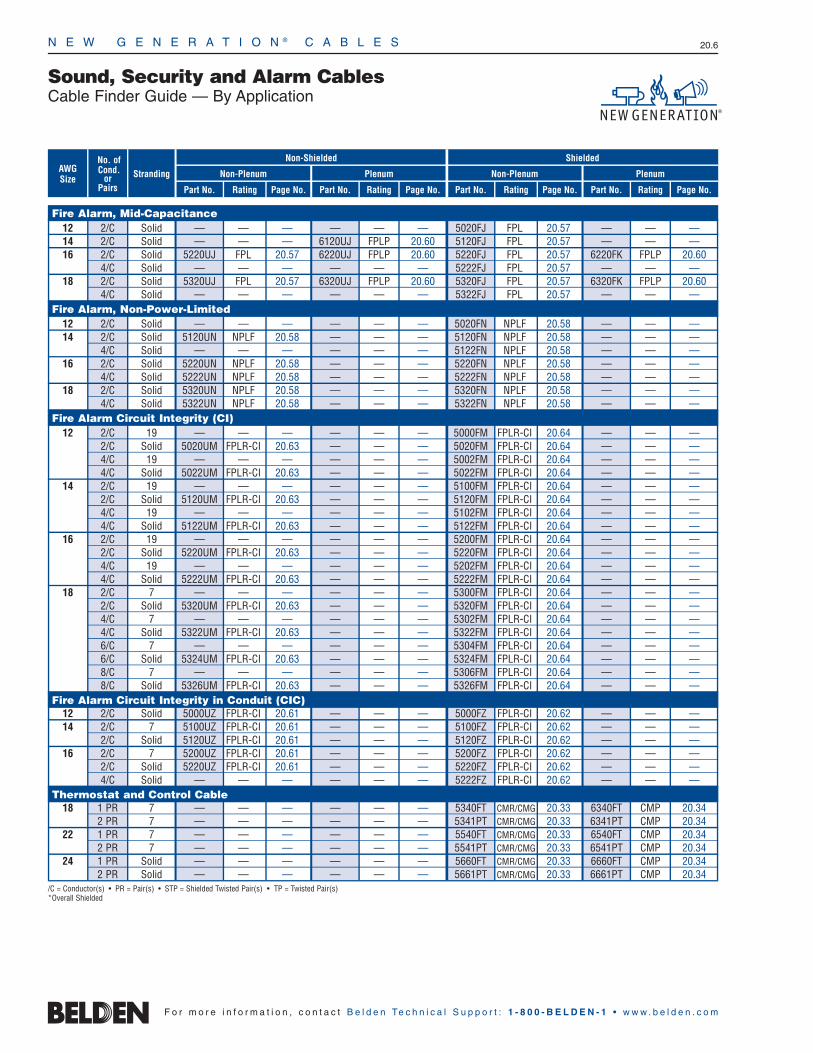
Sound, Security and Alarm CablesCable Finder Guide — By Application
StrandingNo. of Cond.
or Pairs Part No. Rating Page No.
Non-Shielded
Non-Plenum Plenum
Part No. Rating Page No. Part No. Rating Page No. Part No. Rating Page No.
Shielded
Non-Plenum PlenumAWGSize
Fire Alarm, Mid-Capacitance 12 2/C Solid — — — — — — 5020FJ FPL 20.57 — — —14 2/C Solid — — — 6120UJ FPLP 20.60 5120FJ FPL 20.57 — — —16 2/C Solid 5220UJ FPL 20.57 6220UJ FPLP 20.60 5220FJ FPL 20.57 6220FK FPLP 20.60
4/C Solid — — — — — — 5222FJ FPL 20.57 — — —18 2/C Solid 5320UJ FPL 20.57 6320UJ FPLP 20.60 5320FJ FPL 20.57 6320FK FPLP 20.60
4/C Solid — — — — — — 5322FJ FPL 20.57 — — —Fire Alarm, Non-Power-Limited
12 2/C Solid — — — — — — 5020FN NPLF 20.58 — — —14 2/C Solid 5120UN NPLF 20.58 — — — 5120FN NPLF 20.58 — — —
4/C Solid — — — — — — 5122FN NPLF 20.58 — — —16 2/C Solid 5220UN NPLF 20.58 — — — 5220FN NPLF 20.58 — — —
4/C Solid 5222UN NPLF 20.58 — — — 5222FN NPLF 20.58 — — —18 2/C Solid 5320UN NPLF 20.58 — — — 5320FN NPLF 20.58 — — —
4/C Solid 5322UN NPLF 20.58 — — — 5322FN NPLF 20.58 — — —Fire Alarm Circuit Integrity (CI)
12 2/C 19 — — — — — — 5000FM FPLR-CI 20.64 — — —2/C Solid 5020UM FPLR-CI 20.63 — — — 5020FM FPLR-CI 20.64 — — —4/C 19 — — — — — — 5002FM FPLR-CI 20.64 — — —4/C Solid 5022UM FPLR-CI 20.63 — — — 5022FM FPLR-CI 20.64 — — —
14 2/C 19 — — — — — — 5100FM FPLR-CI 20.64 — — —2/C Solid 5120UM FPLR-CI 20.63 — — — 5120FM FPLR-CI 20.64 — — —4/C 19 — — — — — — 5102FM FPLR-CI 20.64 — — —4/C Solid 5122UM FPLR-CI 20.63 — — — 5122FM FPLR-CI 20.64 — — —
16 2/C 19 — — — — — — 5200FM FPLR-CI 20.64 — — —2/C Solid 5220UM FPLR-CI 20.63 — — — 5220FM FPLR-CI 20.64 — — —4/C 19 — — — — — — 5202FM FPLR-CI 20.64 — — —4/C Solid 5222UM FPLR-CI 20.63 — — — 5222FM FPLR-CI 20.64 — — —
18 2/C 7 — — — — — — 5300FM FPLR-CI 20.64 — — —2/C Solid 5320UM FPLR-CI 20.63 — — — 5320FM FPLR-CI 20.64 — — —4/C 7 — — — — — — 5302FM FPLR-CI 20.64 — — —4/C Solid 5322UM FPLR-CI 20.63 — — — 5322FM FPLR-CI 20.64 — — —6/C 7 — — — — — — 5304FM FPLR-CI 20.64 — — —6/C Solid 5324UM FPLR-CI 20.63 — — — 5324FM FPLR-CI 20.64 — — —8/C 7 — — — — — — 5306FM FPLR-CI 20.64 — — —8/C Solid 5326UM FPLR-CI 20.63 — — — 5326FM FPLR-CI 20.64 — — —
Fire Alarm Circuit Integrity in Conduit (CIC) 12 2/C Solid 5000UZ FPLR-CI 20.61 — — — 5000FZ FPLR-CI 20.62 — — —14 2/C 7 5100UZ FPLR-CI 20.61 — — — 5100FZ FPLR-CI 20.62 — — —
2/C Solid 5120UZ FPLR-CI 20.61 — — — 5120FZ FPLR-CI 20.62 — — —16 2/C 7 5200UZ FPLR-CI 20.61 — — — 5200FZ FPLR-CI 20.62 — — —
2/C Solid 5220UZ FPLR-CI 20.61 — — — 5220FZ FPLR-CI 20.62 — — —4/C Solid — — — — — — 5222FZ FPLR-CI 20.62 — — —
Thermostat and Control Cable18 1 PR 7 — — — — — — 5340FT CMR/CMG 20.33 6340FT CMP 20.34
2 PR 7 — — — — — — 5341PT CMR/CMG 20.33 6341PT CMP 20.3422 1 PR 7 — — — — — — 5540FT CMR/CMG 20.33 6540FT CMP 20.34
2 PR 7 — — — — — — 5541PT CMR/CMG 20.33 6541PT CMP 20.3424 1 PR Solid — — — — — — 5660FT CMR/CMG 20.33 6660FT CMP 20.34
2 PR Solid — — — — — — 5661PT CMR/CMG 20.33 6661PT CMP 20.34/C = Conductor(s) • PR = Pair(s) • STP = Shielded Twisted Pair(s) • TP = Twisted Pair(s)*Overall Shielded
N E W G E N E R A T I O N ® C A B L E S 20.6
F o r m o r e i n f o r m a t i o n , c o n t a c t B e l d e n Te c h n i c a l S u p p o r t : 1 - 8 0 0 - B E L D E N - 1 • w w w . b e l d e n . c o m

N E W G E N E R A T I O N ® C A B L E S 20.7
20•
New
Gene
ratio
n®Ca
bles
F o r m o r e i n f o r m a t i o n , c o n t a c t B e l d e n Te c h n i c a l S u p p o r t : 1 - 8 0 0 - B E L D E N - 1 • w w w . b e l d e n . c o m
Sound, Security and Alarm CablesCable Finder Guide — Coax and Composite
Part No. Rating Shield/Braid Coverage Page No.StrandingAWG
SizePart No. Rating
Non-Plenum
Shield/Braid Coverage Page No.
PlenumCoaxSeries or
ComponentType
CATV/MATV CoaxRG-59/U 20 Solid — — — — 6439C8 CMP Duofoil + 80% Aluminum 20.49
20 Solid — — — — 6439Q8 CMP Quad Shield 20.49RG-6/U 18 Solid 5339B5 CM Duofoil + 60% Aluminum 20.48 633938 CMP Duofoil + 90% Aluminum 20.49
18 Solid 5339Q5 CM Quad Shield 20.48 6339Q8 CMP Quad Shield 20.49RG-11/U 14 Solid — — — — 6139B8 CMP Duofoil + 60% Aluminum 20.49
CCTV CoaxMini 59 25 Solid 573945 CM 94% Bare Copper 20.37 673948 CMP 95% Bare Copper 20.39RG-59/U 22 7 551945 CM 95% Bare Copper 20.37 — — — —
20 Solid 543945 CM 95% Bare Copper 20.37 643948 CMP 95% Bare Copper 20.39RG-6/U 18 Solid 533945 CM 95% Bare Copper 20.37 633948 CMP 95% Bare Copper 20.39RG-11/U 14 Solid 513945 CM 95% Bare Copper 20.37 613948 CMP 95% Bare Copper 20.39
CCTV Coax, SurveillanceRG-59/U 20 Solid — — — — 7986LC CMP 95% Bare Copper 20.50RG-6/U 18 Solid — — — — 7985LC CMP 95% Bare Copper 20.50
CATV Coax, Water-blockedRG-59/U 20 Solid 5439W5 CM Duofoil® + 95% TC 20.37 — — — —RG-6/U 18 Solid 5339W5 CM Duofoil + 60% Aluminum 20.37 — — — —
Security CoaxRG-62 22 Solid — — — — 6539Y8 CMP 95% Bare Copper 20.39
Schlage CoaxRG-6/U 18 Solid 5399B5 CM Duobond® + 60% Alum. 20.48 — — — —
CCTV Composite Coax with Unshielded Pair for Control or PowerMini 25 Solid 579945 CM 95% Bare Copper 20.38 679948 CMP 95% Bare Copper 20.38RG-59UTP 20 7 Unshielded UnshieldedRG-59 20 Solid 549945 CM 95% Bare Copper 20.38 649948 CMP 95% Bare Copper 20.38UTP 18 7 Unshielded UnshieldedRG-6 18 Solid 539945 CM 95% Bare Copper 20.38 639948 CMP 95% Bare Copper 20.38UTP 18 7 Unshielded Unshielded
Pan/Tilt /Zoom BananaPeel Composite CoaxRG-59/U 20 Solid 500PTZ CMR 95% Bare Copper Braid 20.42 600PTZ CMP 95% Bare Copper Braid 20.431UTP 23 Solid Unshielded Unshielded2/C 18 7 Unshielded UnshieldedRG-59/U 20 Solid 501PTZ CMR 95% Bare Copper Braid 20.44 601PTZ CMP 95% Bare Copper Braid 20.451STP 22 7 Beldfoil® Beldfoil2/C 18 7 Unshielded UnshieldedRG-59/U 20 Solid 502PTZ CMR 95% Bare Copper Braid 20.46 602PTZ CMP 95% Bare Copper Braid 20.471STP 18 7 Beldfoil Beldfoil2/C 18 7 Unshielded Unshielded
CCTV Surveillance UTP and Composite Cables2/C 16 19 5284US CMR Unshielded 20.51 6284US CMP Unshielded 20.522TP 24 Solid Unshielded Unshielded2/C 16 19 5284UE CMR Unshielded 20.51 6284UE CMP Unshielded 20.522TP 23 Solid Unshielded Unshielded2/C 16 19 5288US CMR Unshielded 20.51 6288US CMP Unshielded 20.524TP 23 Solid Unshielded Unshielded4TP 24 Solid 1583A CM Unshielded 20.40/53 1585A CMP Unshielded 20.41/544TP 24 Solid 1500A CM Unshielded 20.40/53 1501A CMP Unshielded 20.41/544TP 24 Solid 1583R CMR Unshielded 20.40/53 — — — —2TP 24 Solid 1500R CMR Unshielded 20.40/53 — — — —4TP 23 Solid 7881A CMR Unshielded 20.40/53 7882A CMP Unshielded 20.41/54
Access Control BananaPeel® Composite Cables4/C 18 7 558AFS CMR Beldfoil 20.36 658AFS CMP Beldfoil 20.353TP 22 7 Beldfoil Beldfoil 4/C 22 7 Beldfoil Beldfoil 2/C 22 7 Beldfoil Beldfoil 4/C 16 19 538AFS CMR Beldfoil 20.36 638AFS CMP Beldfoil 20.353TP 18 7 Beldfoil Beldfoil 4/C 18 7 Beldfoil Beldfoil 2/C 18 7 Beldfoil Beldfoil
STP = Shielded Twisted Pair • TC = Tinned Copper • TP = Twisted Pair(s) • UTP = Unshielded Twisted Pair • /C = Conductor(s) (Multi-conductor)

N E W G E N E R A T I O N ® C A B L E S 20.8
F o r m o r e i n f o r m a t i o n , c o n t a c t B e l d e n Te c h n i c a l S u p p o r t : 1 - 8 0 0 - B E L D E N - 1 • w w w . b e l d e n . c o m
Unshielded Multi-conductorCM FT1 Rated
Product Description
Bare copper conductors, polypropylene insulation,PVC jacket. Available in Beige, Brown, Orange,Yellow, Green, Blue, Purple, Gray or White jacketcolors (except as noted in footnote). Conductorsmay not be cabled. Sequential footage markingevery two feet.
Color Code: See chart below.
Specifications
Conductor Bare Copper
Insulation Polypropylene
Insulation Thickness .006″ (.152mm)
Jacket PVC
ApprovalsNEC CMCEC CM FT1
NEC Articles 800
Voltage Rating 300V
Temperature Rating 75°C
Applications• Security Systems
• Intercom/PA Systems
• Sound/Audio Systems
• Power-Limited Controls
• Single Line Telephone
• Station Wire (5582UG)
Solid Conductor
Stranded Conductor
StrandingNo. of Cond.
mFt.
StandardLengths
mmInchkg
Standard Unit Weight
Outer JacketThickness Nominal OD
Inch mmLbs.
Security and Alarm CableResidential, Light Commercial and Institutional ApplicationsUnshielded
PartNo.
Unshielded Multi-conductor (NEC CM and CEC CM FT1)
22 AWG5500UG* 2 7 C-500 C-152 3.5 1.6 .015 .38 .114 2.90
U-500 U-152 5.0 2.3C-1000 C-305 7.0 3.2U-1000 U-305 9.0 4.1
5582UG** 4 solid C-500 C-152 6.0 2.7 .015 .38 .122 3.10C-1000 C-305 12.0 5.4U-1000 U-305 13.0 6.0
5502UG 4 7 C-500 C-152 6.5 3.0 .015 .38 .131 3.33U-500 U-152 7.5 3.4
C-1000 C-305 13.0 6.0U-1000 U-305 14.0 6.4
5522UG† 4 solid C-500 C-152 6.0 2.7 .015 .38 .122 3.10u C-1000 C-305 12.0 5.45520UG 2 solid C-500 C-152 3.5 1.6 .015 .38 .106 2.69u C-1000 C-305 7.0 3.218 AWG
5300UG†† 2 7 C-500 C-152 7.5 3.4 .015 .38 .148 3.76U-500 U-152 8.5 3.9
U-1000 U-305 16.0 7.3* U-1000 available in Brown, Gray or Natural only.
** 5582UG available in Brown, Gray, White or Beige only.† 5522UG available in White only.
†† 5300UG available in Gray, Black or Natural only. 5502UG U-500 ft. put-up available in Gray or White only. 5520UG C-500 ft. put-up available in Gray or White only.
Color Code Chart
(5500UG, 5502UG, 5520UG, 5522UG, 5300UG)
Cond. No. Color
1 Black
2 Red
3 White
4 GreenExcept 5582UG which is Black, Red, Yellow, Green
for use as station wire.
Color Code Chart(5582UG)
Cond. No. Color
1 Black
2 Red
3 Yellow
4 Green

N E W G E N E R A T I O N ® C A B L E S 20.9
20•
New
Gene
ratio
n®Ca
bles
StrandingNo. of Cond.
mFt.
StandardLengths
mmInchkg
Standard Unit Weight
Outer JacketThickness Nominal OD
Inch mmLbs.
Security and Alarm CableCommercial ApplicationsUnshielded
F o r m o r e i n f o r m a t i o n , c o n t a c t B e l d e n Te c h n i c a l S u p p o r t : 1 - 8 0 0 - B E L D E N - 1 • w w w . b e l d e n . c o m
PartNo.
Unshielded Multi-conductor (NEC CMR and CEC CMG FT4)
22 AWG5520UE 2 solid C-500 C-152 4.0 1.8 .015 .38 .122 3.10
U-500 U-152 5.5 2.5C-1000 C-305 8.0 3.6U-1000 U-305 9.0 4.1
1000 305 9.0 4.15500UE 2 7 C-500 C-152 4.0 1.8 .015 .38 .128 3.25
U-500 U-152 5.5 2.5500 152 5.5 2.5
C-1000 C-305 8.0 3.6U-1000 U-305 10.0 4.5
1000 305 9.0 4.15501UE 3 7 U-1000 U-305 13.0 5.9 .015 .38 .135 3.43
1000 305 13.0 5.95522UE 4 solid U-1000 U-305 16.0 7.3 .015 .38 .141 3.58
1000 305 16.0 7.35582UE* 4 solid C-500 C-152 7.0 3.2 .015 .38 .141 3.58
U-500 U-152 6.5 3.0U-1000 U-305 12.0 5.5
1000 305 12.0 5.55502UE** 4 7 C-500 C-152 7.5 3.4 .015 .38 .148 3.76
U-500 U-152 9.0 4.1U-1000 U-305 16.0 7.3
1000 305 16.0 7.35503UE 5 7 U-1000 U-305 20.0 9.1 .015 .38 .162 4.11
1000 305 20.0 9.15524UE 6 solid C-500 C-152 10.5 4.8 .015 .38 .168 4.27
1000 305 22.0 10.05504UE** 6 7 C-500 C-152 12.5 5.7 .015 .38 .177 4.50
U-500 U-152 14.0 6.4500 152 13.5 6.1
U-1000 U-305 27.0 12.31000 305 27.0 12.3
5526UE 8 solid 1000 305 28.0 12.7 .015 .38 .182 4.625506UE 8 7 U-1000 U-305 29.0 13.2 .015 .38 .192 4.88
1000 305 30.0 13.65508UE 10 7 U-1000 U-305 36.0 16.3 .015 .38 .226 5.74
1000 305 41.0 18.65529UE 12 solid U-1000 U-305 40.0 18.1 .015 .38 .221 5.61
1000 305 42.0 19.15509UE 12 7 U-500 U-152 21.5 9.8 .015 .38 .233 5.92
U-1000 U-305 42.0 19.11000 305 47.0 21.4
20 AWG5400UE 2 7 C-500 C-152 6.0 2.7 .015 .38 .142 3.61
U-1000 U-305 13.0 5.91000 305 13.0 5.9
5401UE 3 7 500 152 9.0 4.1 .015 .38 .150 3.81U-1000 U-305 18.0 8.2
1000 305 18.0 8.25402UE 4 7 C-500 C-152 10.5 4.8 .015 .38 .165 4.19
U-1000 U-305 23.0 10.51000 305 23.0 10.5
5403UE 5 7 U-1000 U-305 27.0 12.2 .015 .38 .181 4.601000 305 28.0 12.7
5405UE 7 7 500 152 19.0 8.6 .015 .38 .198 5.031000 305 40.0 18.2
5406UE 8 7 U-1000 U-305 41.0 18.6 .015 .38 .215 5.461000 305 43.0 19.5
5407UE 9 7 1000 305 48.0 21.8 .015 .38 .233 5.925408UE 10 7 1000 305 53.0 24.1 .015 .38 .254 6.455409UE 12 7 1000 305 62.0 28.1 .015 .38 .262 6.65540BUE 20 7 1000 305 110.0 49.9 .025 .64 .347 8.81* 5582UE also available in Beige, Brown or White.
** 5502UE and 5504UE also available in White.
Color Code Chart ††
Cond. No. Color
1 Black
2 Red
3 White
4 Green
5 Brown
6 Blue
7 Orange
8 Yellow
9 Purple
10 Gray
Cond. No. Color
11 Pink
12 Tan
13 White/Black
14 White/Red
15 White/Green
16 White/Orange
17 White/Blue
18 White/Brown
19 White/Yellow
20 White/Purple††Except 5582UE which is Black, Red, Yellow, Green for use as station wire.
Unshielded Multi-conductorCMR/CMG FT4 Rated
Product Description
Bare copper conductors, PVC insulation, Gray PVCjacket with rip cord. Sequential footage markingevery two feet.
Color Code: See chart below.
Specifications
Conductor Bare Copper
Insulation PVC
Insulation Thickness .010″ (.254mm)
Jacket PVC
ApprovalsNEC CMRCEC CMG FT4
NEC Articles 800
Voltage Rating 300V
Temperature Rating 75°C
Applications• Security Systems
• Intercom/PA Systems
• Sound/Audio Systems
• Power-Limited Controls
• Single Line Telephone
Solid Conductor
Stranded Conductor
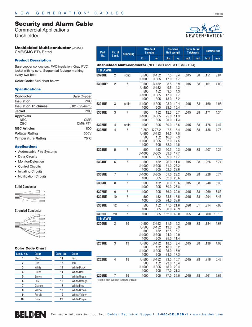
N E W G E N E R A T I O N ® C A B L E S 20.10
F o r m o r e i n f o r m a t i o n , c o n t a c t B e l d e n Te c h n i c a l S u p p o r t : 1 - 8 0 0 - B E L D E N - 1 • w w w . b e l d e n . c o m
StrandingNo. of Cond.
mFt.
StandardLengths
mmInchkg
Standard Unit Weight
Outer JacketThickness Nominal OD
Inch mmLbs.
Security and Alarm CableCommercial ApplicationsUnshielded
PartNo.
Unshielded Multi-conductor (NEC CMR and CEC CMG FT4)
18 AWG5320UE 2 solid C-500 C-152 7.5 3.4 .015 .38 .151 3.84
U-1000 U-305 17.0 7.75300UE* 2 7 C-500 C-152 8.5 3.9 .015 .38 .161 4.09
U-500 U-152 9.5 4.3500 152 9.5 4.3
U-1000 U-305 17.0 7.71000 305 18.0 8.2
5321UE 3 solid U-1000 U-305 23.0 10.4 .015 .38 .160 4.061000 305 23.0 10.4
5301UE 3 7 500 152 12.5 5.7 .015 .38 .171 4.34U-1000 U-305 25.0 11.3
1000 305 25.0 11.35322UE 4 solid 1000 305 30.0 13.6 .015 .38 .176 4.475302UE 4 7 C-250 C-76.2 7.5 3.4 .015 .38 .188 4.78
U-500 U-152 16.5 7.5500 152 16.0 7.3
U-1000 U-305 32.0 14.51000 305 32.0 14.5
5303UE 5 7 500 152 20.5 9.3 .015 .38 .207 5.26U-1000 U-305 39.0 17.7
1000 305 39.0 17.75304UE 6 7 500 152 26.0 11.8 .015 .38 .226 5.74
U-1000 U-305 51.0 23.21000 305 52.0 23.6
5305UE 7 7 U-1000 U-305 51.0 23.2 .015 .38 .226 5.741000 305 52.0 23.6
5306UE 8 7 500 152 30.0 13.6 .015 .38 .248 6.301000 305 59.0 26.8
5307UE 9 7 1000 305 66.0 30.0 .015 .38 .269 6.835308UE 10 7 500 152 38.5 17.5 .015 .38 .294 7.47
1000 305 74.0 33.65309UE 12 7 500 152 47.5 21.6 .020 .51 .314 7.98
1000 305 90.0 40.9530BUE 20 7 1000 305 152.0 69.0 .025 .64 .400 10.1616 AWG
5200UE 2 19 C-500 C-152 11.5 5.2 .015 .38 .184 4.67U-500 U-152 13.0 5.9
500 152 12.5 5.7U-1000 U-305 24.0 10.9
1000 305 25.0 11.45201UE 3 19 U-500 U-152 18.5 8.4 .015 .38 .196 4.98
500 152 18.0 8.2U-1000 U-305 35.0 15.9
1000 305 38.0 17.35202UE 4 19 U-500 U-152 23.5 10.7 .015 .38 .216 5.49
500 152 23.0 10.4U-1000 U-305 45.0 20.4
1000 305 47.0 21.35205UE 7 19 1000 305 77.0 35.0 .015 .38 .261 6.63*5300UE also available in White or Black.
Unshielded Multi-conductor (cont’d.)CMR/CMG FT4 Rated
Product Description
Bare copper conductors, PVC insulation, Gray PVCjacket with rip cord. Sequential footage markingevery two feet.
Color Code: See chart below.
Specifications
Conductor Bare Copper
Insulation PVC
Insulation Thickness .010″ (.254mm)
Jacket PVC
ApprovalsNEC CMRCEC CMG FT4
NEC Articles 800
Voltage Rating 300V
Temperature Rating 75°C
Applications• Addressable Fire Systems
• Data Circuits
• Monitor/Detection
• Control Circuits
• Initiating Circuits
• Notification Circuits
Solid Conductor
Stranded Conductor
Color Code Chart
Cond. No. Color
1 Black
2 Red
3 White
4 Green
5 Brown
6 Blue
7 Orange
8 Yellow
9 Purple
10 Gray
Cond. No. Color
11 Pink
12 Tan
13 White/Black
14 White/Red
15 White/Green
16 White/Orange
17 White/Blue
18 White/Brown
19 White/Yellow
20 White/Purple

N E W G E N E R A T I O N ® C A B L E S 20.11
20•
New
Gene
ratio
n®Ca
bles
StrandingNo. of Cond.
mFt.
StandardLengths
mmInchkg
Standard Unit Weight
Outer JacketThickness Nominal OD
Inch mmLbs.
Security and Alarm CableCommercial ApplicationsUnshielded
F o r m o r e i n f o r m a t i o n , c o n t a c t B e l d e n Te c h n i c a l S u p p o r t : 1 - 8 0 0 - B E L D E N - 1 • w w w . b e l d e n . c o m
PartNo.
Unshielded Multi-conductor (NEC CMR FPLR CL3R)
14 AWG5100UE* 2 19 500 152 20.0 9.1 .015 .38 .234 5.94
U-1000 U-305 38.0 17.21000 305 40.0 18.2
5101UE 3 19 1000 305 56.0 25.5 .015 .38 .249 6.325102UE 4 19 500 152 38.5 17.5 .015 .38 .276 7.01
1000 305 71.0 33.212 AWG
5000UE* 2 19 500 152 29.0 13.2 .015 .38 .268 6.811000 305 57.0 25.9
5001UE 3 19 1000 305 82.0 37.3 .015 .38 .286 7.26*5100UE and 5000UE also available in Red for Fire Alarm (FPLR).
Color Code Chart
Cond. No. Color
1 Black
2 White
3 Red
4 Green
Unshielded Multi-conductorCMR/CL3R Rated
Product Description
Bare copper conductors, PVC insulation, Gray PVCjacket with rip cord. Sequential footage markingevery two feet.
Color Code: See chart below.
Specifications
Conductor Bare Copper
Insulation PVC
Insulation Thickness .014″ (.356mm)
Jacket PVC
ApprovalsNEC CMR FPLR† & CL3R
NEC Articles 725 & 760
Voltage Rating 300V
Temperature Rating 75°C†CMR FPLR dual rating for 5000UE, 5100UE, 5000FE and 5100FE only.
Applications• Security Systems
• Intercom/PA Systems
• Sound/Audio Systems
• Power-Limited Controls
• Single Line Telephone
• Fire Alarm Systems (Red Only) Dual Rated**

N E W G E N E R A T I O N ® C A B L E S 20.12
F o r m o r e i n f o r m a t i o n , c o n t a c t B e l d e n Te c h n i c a l S u p p o r t : 1 - 8 0 0 - B E L D E N - 1 • w w w . b e l d e n . c o m
Shielded Multi-conductorCMR/CMG FT4 Rated
Product Description
Bare copper conductors, PVC insulation, cabled,Beldfoil® shield tape (foil side out) with drain wire,Gray PVC jacket with rip cord. Sequential footagemarking every two feet.
Color Code: See chart below.
Specifications
Conductor Bare Copper
Insulation PVC
Insulation Thickness .010″ (.254mm)
Shield Beldfoil
Jacket PVC
ApprovalsNEC CMRCEC CMG FT4
NEC Articles 800
Voltage Rating 300V
Temperature Rating 75°C
Applications• Security Systems
• Intercom/PA Systems
• Sound/Audio Systems
• Power-Limited Controls
Solid Conductor
Stranded Conductor
StrandingNo. of Cond.
mFt.
StandardLengths
mmInchkg
Standard Unit Weight
Outer JacketThickness Nominal OD
Inch mmLbs.
Security and Alarm CableCommercial ApplicationsShielded
PartNo.
Shielded Multi-conductor (NEC CMR and CEC CMG FT4)
24 AWG5600FE 2 7 U-1000 U-305 11.0 5.0 .015 .38 .120 3.05
1000 305 10.0 4.522 AWG
5520FE 2 solid C-500 C-152 6.5 3.0 .015 .38 .125 3.18C-1000 C-305 13.0 5.9U-1000 U-305 14.0 6.4
1000 305 14.0 6.45500FE 2 7 C-500 C-152 5.5 2.5 .015 .38 .130 3.30
U-500 U-152 6.5 3.0500 152 6.5 3.0
U-1000 U-305 12.0 5.41000 305 12.0 5.4
5521FE 3 solid U-1000 U-305 12.0 5.4 .015 .38 .132 3.351000 305 12.0 5.4
5501FE 3 7 C-500 C-152 7.0 3.2 .015 .38 .138 3.51U-500 U-152 8.0 3.6
500 152 7.5 3.4U-1000 U-305 15.0 6.8
1000 305 15.0 6.85502FE 4 7 C-500 C-152 8.5 3.9 .015 .38 .152 3.86
U-500 U-152 9.5 4.3500 152 9.5 4.3
U-1000 U-305 18.0 8.21000 305 18.0 8.2
5503FE 5 7 1000 305 22.0 10.0 .015 .38 .165 4.195504FE 6 7 C-500 C-152 13.5 6.1 .015 .38 .179 4.55
U-500 U-152 15.0 6.8U-1000 U-305 29.0 13.2
1000 305 29.0 13.25506FE 8 7 U-500 U-152 16.5 7.5 .015 .38 .196 4.98
U-1000 U-305 32.0 14.51000 305 32.0 14.5
5508FE 10 7 U-500 U-152 19.5 8.9 .015 .38 .230 5.84U-1000 U-305 38.0 17.2
1000 305 44.0 20.020 AWG
5400FE 2 7 C-500 C-152 8.0 3.6 .015 .38 .145 3.68U-500 U-152 9.0 4.1
500 152 8.5 3.9U-1000 U-305 17.0 7.2
1000 305 17.0 7.25401FE 3 7 U-500 U-152 11.0 5.0 .015 .38 .153 3.89
500 152 10.5 4.8U-1000 U-305 21.0 9.5
1000 305 21.0 9.55402FE 4 7 C-500 C-152 12.0 5.4 .015 .38 .168 4.27
U-500 U-152 12.5 5.7500 152 13.0 5.9
U-1000 U-305 25.0 11.31000 305 26.0 11.8
5403FE 5 7 U-1000 U-305 30.0 13.6 .015 .38 .184 4.671000 305 30.0 13.6
5405FE 7 7 U-1000 U-305 39.0 17.7 .015 .38 .201 5.111000 305 40.0 18.2
5407FE 9 7 1000 305 51.0 23.2 .015 .38 .236 5.99
Shorting Fold
Color Code Chart
Cond. No. Color
1 Black
2 Red
3 White
4 Green
5 Brown
6 Blue
7 Orange
8 Yellow
9 Purple
10 Gray
Shorting Fold

N E W G E N E R A T I O N ® C A B L E S 20.13
20•
New
Gene
ratio
n®Ca
bles
StrandingNo. of Cond.
mFt.
StandardLengths
mmInchkg
Standard Unit Weight
Outer JacketThickness Nominal OD
Inch mmLbs.
Security and Alarm CableCommercial ApplicationsShielded
F o r m o r e i n f o r m a t i o n , c o n t a c t B e l d e n Te c h n i c a l S u p p o r t : 1 - 8 0 0 - B E L D E N - 1 • w w w . b e l d e n . c o m
PartNo.
Shielded Multi-conductor (NEC CMR and CEC CMG FT4)
18 AWG5320FE 2 solid C-500 C-152 10.0 4.6 .015 .38 .155 3.94
U-1000 U-305 21.0 9.51000 305 21.0 9.5
5300FE 2 7 C-500 C-152 11.0 5.0 .015 .38 .165 4.19U-500 U-152 12.0 5.5
500 152 12.0 5.5U-1000 U-305 23.0 10.4
1000 305 23.0 10.45301FE 3 7 U-500 U-152 15.5 7.0 .015 .38 .175 4.45
500 152 15.0 6.8U-1000 U-305 30.0 13.6
1000 305 30.0 13.65302FE 4 7 C-250 C-76 8.8 4.0 .015 .38 .192 4.88
U-500 U-152 19.0 8.6500 152 20.5 9.3
U-1000 U-305 36.0 16.31000 305 37.0 16.8
5303FE 5 7 U-500 U-152 22.5 10.2 .015 .38 .211 5.36500 152 22.5 10.2
U-1000 U-305 43.0 19.51000 305 45.0 20.5
5304FE 6 7 U-500 U-152 28.5 12.9 .015 .38 .230 5.84500 152 26.0 11.8
1000 305 57.0 25.95305FE 7 7 1000 305 57.0 25.9 .015 .38 .230 5.845306FE* 8 7 500 152 32.0 14.5 .015 .38 .270 6.86
1000 305 64.0 29.15307FE 9 7 1000 305 71.0 32.3 .015 .38 .272 6.9116 AWG
5200FE** 2 19 U-500 U-152 16.5 7.5 .015 .38 .188 4.78500 152 16.5 7.5
U-1000 U-305 31.0 14.11000 305 32.0 14.5
5201FE 3 19 500 152 21.5 9.8 .015 .38 .200 5.08U-1000 U-305 42.0 19.1
1000 305 42.0 19.15202FE 4 19 500 152 26.5 12.0 .015 .38 .220 5.59
1000 305 54.0 24.5
Shielded Multi-conductor (NEC CL3R)
14 AWG5100FE† 2 19 500 152 28.5 12.9 .015 .38 .238 6.05
U-1000 U-305 49.0 22.21000 305 51.0 23.2
5101FE 3 19 1000 305 66.0 30.0 .015 .38 .253 6.4312 AWG
5000FE† 2 19 500 152 36.5 16.6 .015 .38 .272 6.911000 305 67.0 30.5
* 5306FE also available in Natural.** 5200FE also available in White.
† 5100FE and 5000FE available in Red or Gray for Fire Alarm (FPLR).
Shorting Fold
Shorting Fold
Cond. No. Color
1 Black
2 Red
3 White
4 Green
5 Brown
Cond. No. Color
6 Blue
7 Orange
8 Yellow
9 Purple
10 Gray
Color Code Chart (18 to16 AWG)
(14 to12 AWG)
Cond. No. Color
1 Black
2 White
3 Red
Shielded Multi-conductor (cont’d.)CMR/CMG FT4 Rated or CL3R Rated
Product Description
Bare copper conductors, PVC insulation, cabled,Beldfoil® shield tape (foil side out) with drain wire,Gray PVC jacket with rip cord. Sequential footagemarking every two feet.
Color Code: See chart below.
Specifications
Conductor Bare Copper
Insulation PVC
Insulation Thickness18 to 16 AWG .010″ (.254mm)14 to 12 AWG .014″ (.356mm)
Shield Beldfoil
Jacket PVC
ApprovalsNEC (18 to 16 AWG) CMR FPLR†
CEC (18 to 16 AWG) CMG FT4NEC (14 to 12 AWG) CL3R
NEC Articles18 to 16 AWG 80014 to 12 AWG 725
Voltage Rating 300V
Temperature Rating 75°C†CMR FPLR dual rating for 5000UE, 5100UE, 5000FE and 5100FE only.
Applications• Security Systems
• Intercom/PA Systems
• Sound/Audio Systems
• Power-Limited Controls
• Fire Alarm Systems (Red Only) Dual Rated†
Solid Conductor
Stranded Conductor

N E W G E N E R A T I O N ® C A B L E S 20.14
F o r m o r e i n f o r m a t i o n , c o n t a c t B e l d e n Te c h n i c a l S u p p o r t : 1 - 8 0 0 - B E L D E N - 1 • w w w . b e l d e n . c o m
StrandingNo. of Cond.
mFt.
StandardLengths
mmInchkg
Standard Unit Weight
Outer JacketThickness Nominal OD
Inch mmLbs.
Security and Alarm CableWater-Blocked for Use in Underground DuctsUnshielded and Shielded
PartNo.
Water-blocked, Unshielded Multi-conductor (NEC CM and CEC CM FT1)
18 AWG5300U1 2 7 U-500 U-152 12.0 5.5 .025 .64 .207 5.26
500 152 13.5 6.1U-1000 U-305 22.0 10.0
1000 305 24.0 10.9
Water-blocked, Shielded Multi-conductor (NEC CM and CEC CM FT1)
22 AWG5500F1 2 7 U-500 U-152 9.0 4.1 .025 .64 .192 4.88
500 152 9.0 4.1U-1000 U-305 16.0 7.3
1000 305 17.0 7.720 AWG
5400F1 2 7 U-500 U-152 11.5 5.2 .025 .64 .206 5.23500 152 11.0 5.0
U-1000 U-305 21.0 9.51000 305 21.0 9.5
18 AWG5300F1 2 7 U-500 U-152 15.0 6.8 .025 .64 .222 5.64
500 152 15.0 6.8U-1000 U-305 29.0 13.2
1000 305 30.0 13.6
Water-blocked,Unshielded Multi-conductorCM FT1 Rated
Product Description
Tinned copper conductors, PVC insulation, cabledwith overall water-blocking tape, Gray PVC jacketwith rip cord. Sequential footage marking every two feet.
Water-blocked,Shielded Multi-conductorCM FT1 Rated
Product Description
Tinned copper conductors, PVC insulation, cabledwith overall Beldfoil® shield and drain wire, overallwater-blocking tape, Gray PVC jacket with rip cord.Sequential footage marking every two feet.
Color Code: Black, Red.
Specifications
Conductor Tinned Copper
Insulation PVC
Insulation Thickness .010″ (.254mm)
Shield (where applicable) Beldfoil
Jacket PVC
ApprovalsNEC CMCEC CM FT1
NEC Articles 800
Voltage Rating 300V
Temperature Rating 105°C
Applications• Security Systems
• Intercom/PA Systems
• Sound/Audio Systems
• Power-Limited Controls
• Indoor or Outdoor Use
Unshielded Water-blocked
Shielded and Water-blocked
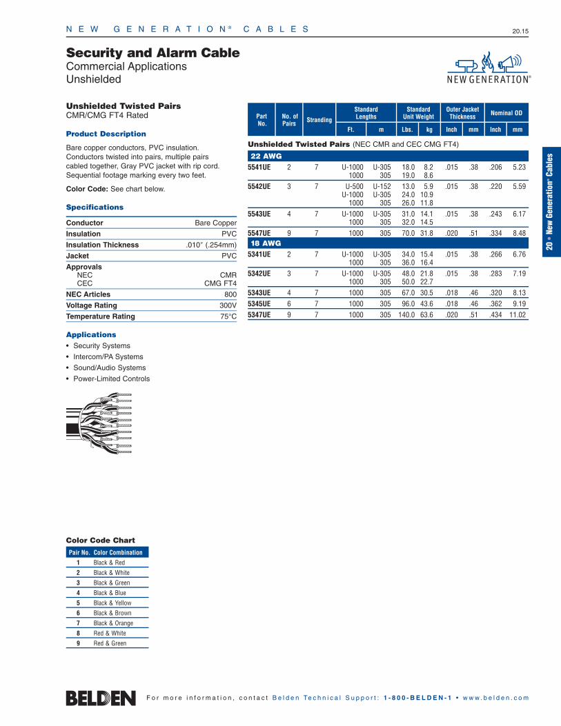
N E W G E N E R A T I O N ® C A B L E S 20.15
20•
New
Gene
ratio
n®Ca
bles
F o r m o r e i n f o r m a t i o n , c o n t a c t B e l d e n Te c h n i c a l S u p p o r t : 1 - 8 0 0 - B E L D E N - 1 • w w w . b e l d e n . c o m
Unshielded Twisted PairsCMR/CMG FT4 Rated
Product Description
Bare copper conductors, PVC insulation. Conductors twisted into pairs, multiple pairs cabled together, Gray PVC jacket with rip cord.Sequential footage marking every two feet.
Color Code: See chart below.
Specifications
Conductor Bare Copper
Insulation PVC
Insulation Thickness .010″ (.254mm)
Jacket PVC
ApprovalsNEC CMRCEC CMG FT4
NEC Articles 800
Voltage Rating 300V
Temperature Rating 75°C
Applications • Security Systems
• Intercom/PA Systems
• Sound/Audio Systems
• Power-Limited Controls
StrandingNo. of Pairs
mFt.
StandardLengths
mmInchkg
Standard Unit Weight
Outer JacketThickness Nominal OD
Inch mmLbs.
Security and Alarm CableCommercial ApplicationsUnshielded
PartNo.
Unshielded Twisted Pairs (NEC CMR and CEC CMG FT4)
22 AWG5541UE 2 7 U-1000 U-305 18.0 8.2 .015 .38 .206 5.23
1000 305 19.0 8.65542UE 3 7 U-500 U-152 13.0 5.9 .015 .38 .220 5.59
U-1000 U-305 24.0 10.91000 305 26.0 11.8
5543UE 4 7 U-1000 U-305 31.0 14.1 .015 .38 .243 6.171000 305 32.0 14.5
5547UE 9 7 1000 305 70.0 31.8 .020 .51 .334 8.4818 AWG
5341UE 2 7 U-1000 U-305 34.0 15.4 .015 .38 .266 6.761000 305 36.0 16.4
5342UE 3 7 U-1000 U-305 48.0 21.8 .015 .38 .283 7.191000 305 50.0 22.7
5343UE 4 7 1000 305 67.0 30.5 .018 .46 .320 8.135345UE 6 7 1000 305 96.0 43.6 .018 .46 .362 9.195347UE 9 7 1000 305 140.0 63.6 .020 .51 .434 11.02
Color Code Chart
Pair No. Color Combination
1 Black & Red
2 Black & White
3 Black & Green
4 Black & Blue
5 Black & Yellow
6 Black & Brown
7 Black & Orange
8 Red & White
9 Red & Green

N E W G E N E R A T I O N ® C A B L E S 20.16
F o r m o r e i n f o r m a t i o n , c o n t a c t B e l d e n Te c h n i c a l S u p p o r t : 1 - 8 0 0 - B E L D E N - 1 • w w w . b e l d e n . c o m
Overall Shielded Twisted PairsCMR/CMG FT4 Rated
Product Description
Bare copper conductors, PVC insulation.Conductors twisted into pairs, multiple pairs cabled together, overall Beldfoil® shield (foil side out) and drain wire, overall Gray PVC jacket with rip cord. Sequential footage marking every two feet.
Color Code: See chart below.
Specifications
Conductor Bare Copper
Insulation PVC
Insulation Thickness .010″ (.254mm)
Shield Beldfoil
Jacket PVC
ApprovalsNEC CMRCEC CMG FT4
NEC Articles 800
Voltage Rating 300V
Temperature Rating 75°C
Applications • Security Systems
• Intercom/PA Systems
• Sound/Audio Systems
• Power-Limited Controls
Solid Conductor
Stranded Conductor
StrandingNo. of Pairs
mFt.
StandardLengths
mmInchkg
Standard Unit Weight
Outer JacketThickness Nominal OD
Inch mmLbs.
Security and Alarm CableCommercial ApplicationsShielded
PartNo.
Overall Shielded Twisted Pairs (NEC CMR and CEC CMG FT4)
22 AWG5561FE 2 solid U-1000 U-305 21.0 9.5 .015 .38 .200 5.08
1000 305 22.0 10.05541FE 2 7 U-500 U-152 11.5 5.2 .015 .38 .209 5.31
U-1000 U-305 21.0 9.51000 305 23.0 10.4
5562FE 3 solid U-1000 U-305 26.0 11.8 .015 .38 .212 5.381000 305 28.0 12.7
5542FE 3 7 U-1000 U-305 27.0 12.3 .015 .38 .223 5.661000 305 29.0 13.2
5563FE 4 solid U-1000 U-305 33.0 15.0 .015 .38 .246 6.255543FE 4 7 1000 305 34.0 15.4 .015 .38 .246 6.255545FE 6 7 U-1000 U-305 46.0 20.9 .015 .38 .278 7.06
1000 305 48.0 21.820 AWG
5441FE 2 7 500 152 15.0 6.8 .015 .38 .235 5.97U-1000 U-305 29.0 13.2
1000 305 30.0 13.25442FE 3 7 U-1000 U-305 38.0 17.2 .015 .38 .252 6.40
1000 305 38.0 17.25445FE 6 7 1000 305 72.0 32.7 .020 .51 .323 8.2018 AWG
5341FE 2 7 500 152 21.0 9.5 .015 .38 .270 6.86U-1000 U-305 40.0 18.1
1000 305 42.0 19.15342FE 3 7 1000 305 52.0 23.6 .015 .38 .275 6.995343FE 4 7 1000 305 70.0 31.8 .015 .38 .318 8.085345FE 6 7 500 152 52.5 23.9 .020 .51 .373 9.47
1000 305 103.0 46.8
Shorting Fold
Color Code Chart
Pair No. Color Combination
1 Black & Red
2 Black & White
3 Black & Green
Pair No. Color Combination
4 Black & Blue
5 Black & Yellow
6 Black & Brown
Shorting Fold

N E W G E N E R A T I O N ® C A B L E S 20.17
20•
New
Gene
ratio
n®Ca
bles
F o r m o r e i n f o r m a t i o n , c o n t a c t B e l d e n Te c h n i c a l S u p p o r t : 1 - 8 0 0 - B E L D E N - 1 • w w w . b e l d e n . c o m
Individually Shielded Twisted PairsCMR/CMG FT4 Rated
Product Description
Bare copper conductors, PVC insulation.Conductors twisted into pairs and individuallyshielded with Beldfoil® tape (aluminum side facing in) and a drain wire, multiple pairs cabled together, Gray PVC jacket with rip cord. Sequential footage marking every two feet.
Color Code: See chart below.
Specifications
Conductor Bare Copper
Insulation PVC
Insulation Thickness .010″ (.254mm)
Shield Beldfoil
Jacket PVC
ApprovalsNEC CMRCEC CMG FT4
NEC Articles 800
Voltage Rating 300V
Temperature Rating 75°C
Applications • Security Systems
• Intercom/PA Systems
• Sound/Audio Systems
• Power-Limited Controls
StrandingNo. of Pairs
mFt.
StandardLengths
mmInchkg
Standard Unit Weight
Outer JacketThickness Nominal OD
Inch mmLbs.
Security and Alarm CableCommercial ApplicationsShielded
PartNo.
Individually Shielded Twisted Pairs (NEC CMR and CEC CMG FT4)
22 AWG5543PE 4 7 1000 305 55.0 25.0 .033 .84 .303 7.70
Color Code Chart
Pair No. Color Combination
1 Black/Red & Red
2 Black/White & White
3 Black/Green & Green
4 Black/Blue & Blue

N E W G E N E R A T I O N ® C A B L E S 20.18
F o r m o r e i n f o r m a t i o n , c o n t a c t B e l d e n Te c h n i c a l S u p p o r t : 1 - 8 0 0 - B E L D E N - 1 • w w w . b e l d e n . c o m
ShieldedTwisted Pair plus Conductor(s)CMR/CMG FT4 Rated
Product Description
Bare copper conductors, PVC insulation, Black/Redpair shielded with Beldfoil® tape (aluminum side facing in) and tinned copper drain wire, cabled with additional insulated conductor(s) as indicated, Gray PVC jacket with rip cord. Sequential footagemarking every two feet.
Color Code: Black & Red (shielded pair), White, Green. (5542GE Black & Red, Black & White,Black & Green pairs).
Specifications
Conductor Bare Copper
Insulation PVC
Insulation Thickness .010″ (.254mm)
Shield Beldfoil
Jacket PVC
ApprovalsNEC CMRCEC CMG FT4
NEC Articles 800
Voltage Rating 300V
Temperature Rating 75°C
Applications • Security Systems
• Intercom/PA Systems
• Sound/Audio Systems
• Power-Limited Controls
Stranding
No. of Pairs +No. ofCond. mFt.
StandardLengths
mmInchkg
Standard Unit Weight
Outer JacketThickness Nominal OD
Inch mmLbs.
Security and Alarm CableCommercial ApplicationsShielded
PartNo.
STP plus Conductor(s) (NEC CMR and CEC CMG FT4)
22 AWG5501GE 1 STP 7 U-1000 U-305 16.0 7.3 .015 .38 .171 4.34
+1/C5502GE 1 STP 7 U-500 U-152 10.0 4.5 .015 .38 .186 4.72
+2/C U-1000 U-305 19.0 8.61000 305 19.0 8.6
5542GE 1 STP 7 U-1000 U-305 26.0 11.8 .015 .38 .220 5.59+2TP
20 AWG5401GE 1 STP 7 1000 305 23.0 10.4 .015 .38 .196 4.98
+1/C5402GE 1 STP 7 U-1000 U-305 26.0 11.8 .015 .38 .200 5.08
+2/C18 AWG
5302GE 1 STP 7 U-1000 U-305 38.0 17.2 .015 .38 .225 5.72+2/C
STP = Shielded Twisted Pair(s) • /C = Conductor(s)
Shorting Fold
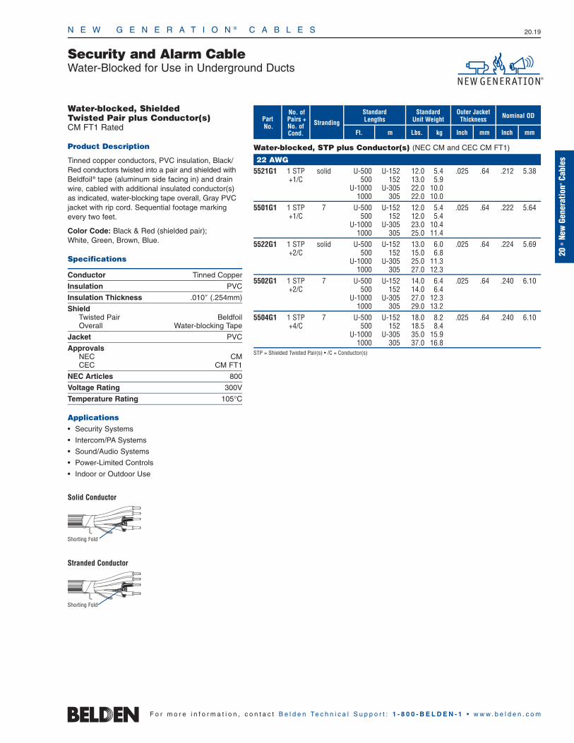
N E W G E N E R A T I O N ® C A B L E S 20.19
20•
New
Gene
ratio
n®Ca
bles
F o r m o r e i n f o r m a t i o n , c o n t a c t B e l d e n Te c h n i c a l S u p p o r t : 1 - 8 0 0 - B E L D E N - 1 • w w w . b e l d e n . c o m
Water-blocked, ShieldedTwisted Pair plus Conductor(s)CM FT1 Rated
Product Description
Tinned copper conductors, PVC insulation, Black/Red conductors twisted into a pair and shielded withBeldfoil® tape (aluminum side facing in) and drainwire, cabled with additional insulated conductor(s)as indicated, water-blocking tape overall, Gray PVCjacket with rip cord. Sequential footage markingevery two feet.
Color Code: Black & Red (shielded pair); White, Green, Brown, Blue.
Specifications
Conductor Tinned Copper
Insulation PVC
Insulation Thickness .010″ (.254mm)
ShieldTwisted Pair BeldfoilOverall Water-blocking Tape
Jacket PVC
ApprovalsNEC CMCEC CM FT1
NEC Articles 800
Voltage Rating 300V
Temperature Rating 105°C
Applications• Security Systems
• Intercom/PA Systems
• Sound/Audio Systems
• Power-Limited Controls
• Indoor or Outdoor Use
Solid Conductor
Stranded Conductor
Stranding
No. of Pairs +No. ofCond. mFt.
StandardLengths
mmInchkg
Standard Unit Weight
Outer JacketThickness Nominal OD
Inch mmLbs.
Security and Alarm CableWater-Blocked for Use in Underground Ducts
PartNo.
Water-blocked, STP plus Conductor(s) (NEC CM and CEC CM FT1)
22 AWG5521G1 1 STP solid U-500 U-152 12.0 5.4 .025 .64 .212 5.38
+1/C 500 152 13.0 5.9U-1000 U-305 22.0 10.0
1000 305 22.0 10.05501G1 1 STP 7 U-500 U-152 12.0 5.4 .025 .64 .222 5.64
+1/C 500 152 12.0 5.4U-1000 U-305 23.0 10.4
1000 305 25.0 11.45522G1 1 STP solid U-500 U-152 13.0 6.0 .025 .64 .224 5.69
+2/C 500 152 15.0 6.8U-1000 U-305 25.0 11.3
1000 305 27.0 12.35502G1 1 STP 7 U-500 U-152 14.0 6.4 .025 .64 .240 6.10
+2/C 500 152 14.0 6.4U-1000 U-305 27.0 12.3
1000 305 29.0 13.25504G1 1 STP 7 U-500 U-152 18.0 8.2 .025 .64 .240 6.10
+4/C 500 152 18.5 8.4U-1000 U-305 35.0 15.9
1000 305 37.0 16.8 STP = Shielded Twisted Pair(s) • /C = Conductor(s)
Shorting Fold
Shorting Fold

N E W G E N E R A T I O N ® C A B L E S 20.20
F o r m o r e i n f o r m a t i o n , c o n t a c t B e l d e n Te c h n i c a l S u p p o r t : 1 - 8 0 0 - B E L D E N - 1 • w w w . b e l d e n . c o m
Unshielded Multi-conductorCMP FT6 Rated
Product Description
Bare copper conductors, Flamarrest® insulation,conductors cabled, Natural Flamarrest jacket, rip cord. Sequential footage marking every two feet.
Color Code: See chart below.
Specifications
Conductor Bare Copper
Insulation Flamarrest
Insulation Thickness .009″ (.229mm)
Jacket Flamarrest
ApprovalsNEC CMPCEC CMP FT6
NEC Articles 800
Voltage Rating 300V
Temperature Rating 75°C
Applications• Security Systems
• Intercom/PA Systems
• Sound/Audio Systems
• Power-Limited Controls
Solid Conductor
Stranded Conductor
StrandingNo. of Cond.
mFt.
StandardLengths
mmInchkg
Standard Unit Weight
Outer JacketThickness Nominal OD
Inch mmLbs.
Security and Alarm CableCommercial ApplicationsUnshielded, Plenum-Rated
PartNo.
Unshielded Multi-conductor (NEC CMP and CEC CMP FT6)
22 AWG6520UE 2 solid U-1000 U-305 10.0 4.5 .015 .38 .118 3.00
1000 305 9.0 4.16500UE 2 7 C-500 C-152 4.5 2.0 .015 .38 .124 3.15
C-1000 C-305 9.0 4.1U-1000 U-305 10.0 4.5
1000 305 10.0 4.56521UE 3 solid 1000 305 13.0 5.9 .015 .38 .125 3.186501UE 3 7 U-1000 U-305 14.0 6.4 .015 .38 .131 3.33
1000 305 13.0 5.96522UE 4 solid U-500 U-152 8.5 3.9 .015 .38 .136 3.45
U-1000 U-305 17.0 7.71000 305 16.0 7.3
6502UE 4 7 C-500 C-152 8.0 3.6 .015 .38 .143 3.63U-500 U-152 9.0 4.1
500 152 8.5 3.9U-1000 U-305 17.0 7.7
1000 305 17.0 7.76524UE 6 solid C-500 C-152 10.5 4.8 .015 .38 .162 4.11
U-1000 U-305 23.0 10.56504UE 6 7 C-500 C-152 11.0 5.0 .015 .38 .171 4.34
500 152 12.0 5.5U-1000 U-305 24.0 10.9
1000 305 24.0 10.96506UE 8 7 U-500 U-152 15.5 7.0 .015 .38 .186 4.72
U-1000 U-305 30.0 13.61000 305 31.0 14.1
6508UE 10 7 U-1000 U-305 37.0 16.8 .015 .38 .218 5.541000 305 43.0 19.5
6509UE 12 7 U-500 U-152 22.5 10.2 .015 .38 .225 5.72U-1000 U-305 43.0 19.5
1000 305 45.0 20.420 AWG
6400UE 2 7 C-500 C-152 6.0 2.7 .015 .38 .138 3.51500 152 7.0 3.2
U-1000 U-305 14.0 6.41000 305 14.0 6.4
6401UE 3 7 U-1000 U-305 19.0 8.6 .015 .38 .146 3.711000 305 18.0 8.25000 1524 90.0 40.9
6402UE 4 7 U-1000 U-305 24.0 10.9 .015 .38 .160 4.061000 305 24.0 10.9
6403UE 5 7 U-1000 U-305 28.0 12.7 .015 .38 .176 4.471000 305 28.0 12.7
6406UE 8 7 1000 305 44.0 20.0 .015 .38 .209 5.31Color Code Chart
Cond. No. Color
1 Black
2 Red
3 White
4 Green
5 Brown
6 Blue
Cond. No. Color
7 Orange
8 Yellow
9 Purple
10 Gray
11 Pink
12 Tan
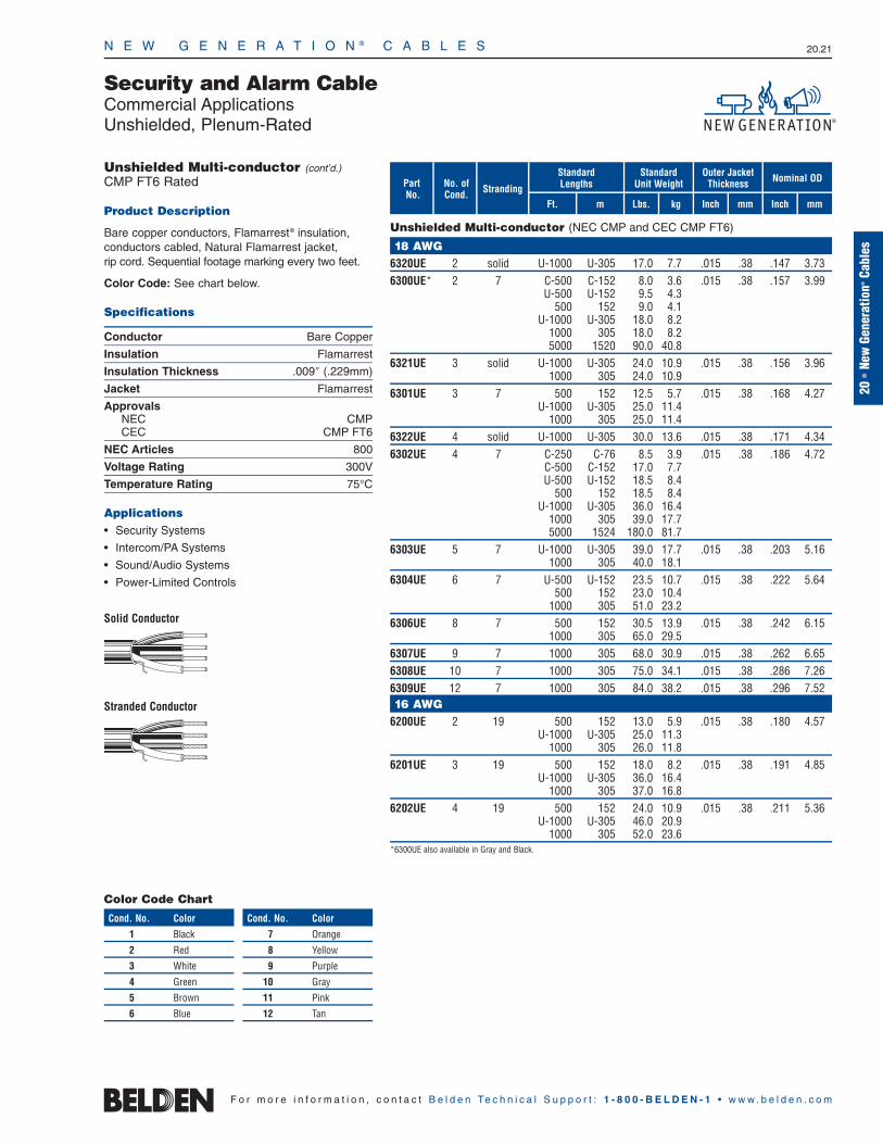
N E W G E N E R A T I O N ® C A B L E S 20.21
20•
New
Gene
ratio
n®Ca
bles
F o r m o r e i n f o r m a t i o n , c o n t a c t B e l d e n Te c h n i c a l S u p p o r t : 1 - 8 0 0 - B E L D E N - 1 • w w w . b e l d e n . c o m
StrandingNo. of Cond.
mFt.
StandardLengths
mmInchkg
Standard Unit Weight
Outer JacketThickness Nominal OD
Inch mmLbs.
Security and Alarm CableCommercial ApplicationsUnshielded, Plenum-Rated
PartNo.
Unshielded Multi-conductor (NEC CMP and CEC CMP FT6)
18 AWG6320UE 2 solid U-1000 U-305 17.0 7.7 .015 .38 .147 3.736300UE* 2 7 C-500 C-152 8.0 3.6 .015 .38 .157 3.99
U-500 U-152 9.5 4.3500 152 9.0 4.1
U-1000 U-305 18.0 8.21000 305 18.0 8.25000 1520 90.0 40.8
6321UE 3 solid U-1000 U-305 24.0 10.9 .015 .38 .156 3.961000 305 24.0 10.9
6301UE 3 7 500 152 12.5 5.7 .015 .38 .168 4.27U-1000 U-305 25.0 11.4
1000 305 25.0 11.46322UE 4 solid U-1000 U-305 30.0 13.6 .015 .38 .171 4.346302UE 4 7 C-250 C-76 8.5 3.9 .015 .38 .186 4.72
C-500 C-152 17.0 7.7U-500 U-152 18.5 8.4
500 152 18.5 8.4U-1000 U-305 36.0 16.4
1000 305 39.0 17.75000 1524 180.0 81.7
6303UE 5 7 U-1000 U-305 39.0 17.7 .015 .38 .203 5.161000 305 40.0 18.1
6304UE 6 7 U-500 U-152 23.5 10.7 .015 .38 .222 5.64500 152 23.0 10.4
1000 305 51.0 23.26306UE 8 7 500 152 30.5 13.9 .015 .38 .242 6.15
1000 305 65.0 29.56307UE 9 7 1000 305 68.0 30.9 .015 .38 .262 6.656308UE 10 7 1000 305 75.0 34.1 .015 .38 .286 7.266309UE 12 7 1000 305 84.0 38.2 .015 .38 .296 7.5216 AWG
6200UE 2 19 500 152 13.0 5.9 .015 .38 .180 4.57U-1000 U-305 25.0 11.3
1000 305 26.0 11.86201UE 3 19 500 152 18.0 8.2 .015 .38 .191 4.85
U-1000 U-305 36.0 16.41000 305 37.0 16.8
6202UE 4 19 500 152 24.0 10.9 .015 .38 .211 5.36U-1000 U-305 46.0 20.9
1000 305 52.0 23.6*6300UE also available in Gray and Black.
Unshielded Multi-conductor (cont’d.)CMP FT6 Rated
Product Description
Bare copper conductors, Flamarrest® insulation,conductors cabled, Natural Flamarrest jacket, rip cord. Sequential footage marking every two feet.
Color Code: See chart below.
Specifications
Conductor Bare Copper
Insulation Flamarrest
Insulation Thickness .009″ (.229mm)
Jacket Flamarrest
ApprovalsNEC CMPCEC CMP FT6
NEC Articles 800
Voltage Rating 300V
Temperature Rating 75°C
Applications• Security Systems
• Intercom/PA Systems
• Sound/Audio Systems
• Power-Limited Controls
Solid Conductor
Stranded Conductor
Color Code Chart
Cond. No. Color
1 Black
2 Red
3 White
4 Green
5 Brown
6 Blue
Cond. No. Color
7 Orange
8 Yellow
9 Purple
10 Gray
11 Pink
12 Tan
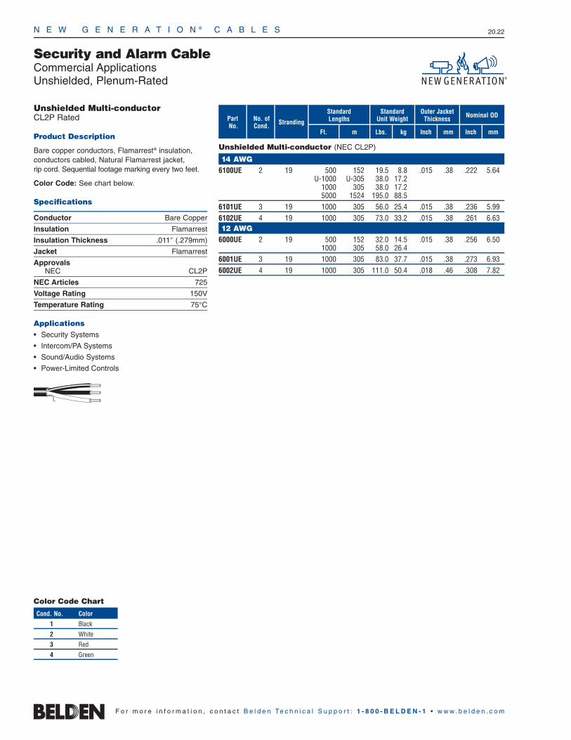
N E W G E N E R A T I O N ® C A B L E S 20.22
F o r m o r e i n f o r m a t i o n , c o n t a c t B e l d e n Te c h n i c a l S u p p o r t : 1 - 8 0 0 - B E L D E N - 1 • w w w . b e l d e n . c o m
Unshielded Multi-conductorCL2P Rated
Product Description
Bare copper conductors, Flamarrest® insulation,conductors cabled, Natural Flamarrest jacket, rip cord. Sequential footage marking every two feet.
Color Code: See chart below.
Specifications
Conductor Bare Copper
Insulation Flamarrest
Insulation Thickness .011″ (.279mm)
Jacket Flamarrest
ApprovalsNEC CL2P
NEC Articles 725
Voltage Rating 150V
Temperature Rating 75°C
Applications• Security Systems
• Intercom/PA Systems
• Sound/Audio Systems
• Power-Limited Controls
StrandingNo. of Cond.
mFt.
StandardLengths
mmInchkg
Standard Unit Weight
Outer JacketThickness Nominal OD
Inch mmLbs.
Security and Alarm CableCommercial ApplicationsUnshielded, Plenum-Rated
PartNo.
Unshielded Multi-conductor (NEC CL2P)
14 AWG6100UE 2 19 500 152 19.5 8.8 .015 .38 .222 5.64
U-1000 U-305 38.0 17.21000 305 38.0 17.25000 1524 195.0 88.5
6101UE 3 19 1000 305 56.0 25.4 .015 .38 .236 5.996102UE 4 19 1000 305 73.0 33.2 .015 .38 .261 6.6312 AWG
6000UE 2 19 500 152 32.0 14.5 .015 .38 .256 6.501000 305 58.0 26.4
6001UE 3 19 1000 305 83.0 37.7 .015 .38 .273 6.936002UE 4 19 1000 305 111.0 50.4 .018 .46 .308 7.82
Color Code Chart
Cond. No. Color
1 Black
2 White
3 Red
4 Green

N E W G E N E R A T I O N ® C A B L E S 20.23
20•
New
Gene
ratio
n®Ca
bles
F o r m o r e i n f o r m a t i o n , c o n t a c t B e l d e n Te c h n i c a l S u p p o r t : 1 - 8 0 0 - B E L D E N - 1 • w w w . b e l d e n . c o m
Shielded Multi-conductorCMP FT6 Rated
Product Description
Bare copper conductors, Flamarrest® insulation,conductors cabled, overall Beldfoil® tape shield (foil side out) and drain wire, Natural Flamarrestjacket with rip cord. Sequential footage markingevery two feet.
Color Code: See chart below.
Specifications
Conductor Bare Copper
Insulation Flamarrest
Insulation Thickness .009″ (.229mm)
Shield Beldfoil
Jacket Flamarrest
ApprovalsNEC CMPCEC CMP FT6
NEC Articles 800
Voltage Rating 300V
Temperature Rating 75°C
Applications• Security Systems
• Intercom/PA Systems
• Sound/Audio Systems
• Power-Limited Controls
Solid Conductor
Stranded Conductor
StrandingNo. of Cond.
mFt.
StandardLengths
mmInchkg
Standard Unit Weight
Outer JacketThickness Nominal OD
Inch mmLbs.
Security and Alarm CableCommercial ApplicationsShielded, Plenum-Rated
PartNo.
Shielded Multi-conductor (NEC CMP and CEC CMP FT6)
22 AWG6520FE 2 solid C-500 C-152 6.0 2.7 .015 .38 .122 3.10
C-1000 C-305 12.0 5.4U-1000 U-305 13.0 5.9
1000 305 13.0 5.96500FE 2 7 C-500 C-152 5.5 2.5 .015 .38 .128 3.25
U-500 U-152 7.0 3.2500 152 7.0 3.2
C-1000 C-305 11.0 5.0U-1000 U-305 13.0 5.9
1000 305 13.0 5.96521FE 3 solid 1000 305 16.0 7.3 .015 .38 .129 3.286501FE 3 7 500 152 8.0 3.6 .015 .38 .135 3.43
U-1000 U-305 16.0 7.31000 305 16.0 7.3
6502FE 4 7 C-500 C-152 9.0 4.1 .015 .38 .147 3.73500 152 10.0 4.5
U-1000 U-305 19.0 8.61000 305 20.0 9.1
6504FE 6 7 C-500 C-152 9.0 4.1 .015 .38 .175 4.45U-500 U-152 13.5 6.1
500 152 13.5 6.1U-1000 U-305 26.0 11.8
1000 305 26.0 11.86506FE 8 7 U-1000 U-305 33.0 15.0 .015 .38 .190 4.83
1000 305 35.0 15.96508FE 10 7 U-1000 U-305 40.0 18.1 .015 .38 .222 5.64
1000 305 42.0 19.020 AWG
6420FE 2 solid C-500 C-152 7.0 3.2 .015 .38 .134 3.40U-1000 U-305 16.0 7.3
1000 305 15.0 6.86400FE 2 7 C-500 C-152 7.5 3.4 .015 .38 .142 3.61
U-1000 U-305 17.0 7.71000 305 17.0 7.7
6401FE 3 7 U-1000 U-305 21.0 9.5 .015 .38 .150 3.811000 305 22.0 10.0
6402FE 4 7 U-1000 U-305 26.0 11.8 .015 .38 .164 4.171000 305 27.0 12.3
6405FE 7 7 1000 305 41.0 18.6 .015 .38 .196 4.976407FE 9 7 1000 305 52.0 23.6 .015 .38 .229 5.82Shorting Fold
Color Code Chart
Cond. No. Color
1 Black
2 Red
3 White
4 Green
5 Brown
6 Blue
Cond. No. Color
7 Orange
8 Yellow
9 Purple
10 Gray
11 Pink
12 Tan
Shorting Fold

N E W G E N E R A T I O N ® C A B L E S 20.24
F o r m o r e i n f o r m a t i o n , c o n t a c t B e l d e n Te c h n i c a l S u p p o r t : 1 - 8 0 0 - B E L D E N - 1 • w w w . b e l d e n . c o m
Shielded Multi-conductor (cont’d.)CMP FT6 Rated or CL2P Rated
Product Description
Bare copper conductors, Flamarrest® insulation,conductors cabled, overall Beldfoil® tape shield (foil side out) and drain wire, Natural Flamarrestjacket with rip cord. Sequential footage markingevery two feet.
Color Code: See chart below.
Specifications
Conductor Bare Copper
Insulation Flamarrest
Insulation Thickness18 and 16 AWG .009″ (.229mm)14 and 12 AWG .011″ (.279mm)
Shield Beldfoil
Jacket Flamarrest
ApprovalsNEC (18 and 16 AWG) CMPCEC (18 and 16 AWG) CMP FT6NEC (14 and 12 AWG) CL2P
NEC Articles18 and 16 AWG 80014 and 12 AWG 725
Voltage Rating18 and 16 AWG 300V14 and 12 AWG 150V
Temperature Rating 75°C
Applications• Security Systems
• Intercom/PA Systems
• Sound/Audio Systems
• Power-Limited Controls
Solid Conductor
Stranded Conductor
StrandingNo. of Cond.
mFt.
StandardLengths
mmInchkg
Standard Unit Weight
Outer JacketThickness Nominal OD
Inch mmLbs.
Security and Alarm CableCommercial ApplicationsShielded, Plenum-Rated
PartNo.
Shielded Multi-conductor (NEC CMP and CEC CMP FT6)
18 AWG6320FE 2 solid C-500 C-152 10.5 4.8 .015 .38 .150 3.89
1000 305 22.0 10.06300FE 2 7 C-500 C-152 11.0 5.0 .015 .38 .162 4.11
U-500 U-152 12.0 5.4500 152 12.0 5.4
U-1000 U-305 23.0 10.41000 305 23.0 10.4
6301FE 3 7 U-500 U-152 15.5 7.0 .015 .38 .172 4.37U-1000 U-305 30.0 13.6
1000 305 31.0 14.16302FE 4 7 C-250 C-76 8.8 4.0 .015 .38 .188 4.78
U-500 U-152 19.5 8.9500 152 19.0 8.6
U-1000 U-305 37.0 16.81000 305 37.0 16.8
6304FE 6 7 C-250 C-76 12.0 5.4 .015 .38 .226 5.74U-500 U-152 25.5 11.61000 305 52.0 23.6
6306FE 8 7 1000 305 66.0 30.0 .015 .38 .246 6.256307FE 9 7 500 152 39.5 18.0 .015 .38 .266 6.76
1000 305 73.0 33.26309FE 12 7 500 152 50.5 22.9 .018 .46 .306 7.77
1000 305 99.0 45.016 AWG
6200FE 2 19 500 152 16.5 7.5 .015 .38 .184 4.671000 305 33.0 15.0
6201FE 3 19 500 152 22.5 10.2 .015 .38 .195 4.95U-1000 U-305 43.0 19.5
1000 305 45.0 20.56202FE 4 19 500 152 29.0 13.2 .015 .38 .215 5.46
1000 305 59.0 26.8
Shielded Multi-conductor (NEC CL2P)
14 AWG6100FE 2 19 500 152 25.0 11.3 .015 .38 .220 5.59
U-1000 U-305 49.0 22.21000 305 51.0 23.1
6101FE 3 19 1000 305 66.0 29.9 .015 .38 .234 5.9412 AWG
6000FE 2 19 500 152 36.0 16.4 .015 .38 .260 6.601000 305 68.0 30.9
Cond. No. Color
1 Black
2 Red
3 White
4 Green
5 Brown
6 Blue
Cond. No. Color
7 Orange
8 Yellow
9 Purple
10 Gray
11 Pink
12 Tan
Shorting Fold
Shorting Fold
(14 to12 AWG)
Cond. No. Color
1 Black
2 White
3 Red
Color Code Chart (18 to16 AWG)

N E W G E N E R A T I O N ® C A B L E S 20.25
20•
New
Gene
ratio
n®Ca
bles
F o r m o r e i n f o r m a t i o n , c o n t a c t B e l d e n Te c h n i c a l S u p p o r t : 1 - 8 0 0 - B E L D E N - 1 • w w w . b e l d e n . c o m
Unshielded Twisted PairsCMP FT6 Rated
Product Description
Bare copper conductors, Flamarrest® insulation,twisted into pairs, multiple pairs cabled together,Natural Flamarrest jacket with rip cord. Sequentialfootage marking every two feet.
Color Code: See chart below.
Specifications
Conductor Bare Copper
Insulation Flamarrest
Insulation Thickness .009″ (.229mm)
Jacket Flamarrest
ApprovalsNEC CMPCEC CMP FT6
NEC Articles 800
Voltage Rating 300V
Temperature Rating 75°C
Applications• Security Systems
• Intercom/PA Systems
• Sound/Audio Systems
• Power-Limited Controls
Solid Conductor
Stranded Conductor
StrandingNo. of Pairs
mFt.
StandardLengths
mmInchkg
Standard Unit Weight
Outer JacketThickness Nominal OD
Inch mmLbs.
Security and Alarm CableCommercial ApplicationsUnshielded, Plenum-Rated
PartNo.
Unshielded Twisted Pairs (NEC CMP and CEC CMP FT6)
22 AWG6561UE 2 solid 1000 305 19.0 8.6 .015 .38 .188 4.786541UE 2 7 U-1000 U-305 19.0 8.6 .015 .38 .199 5.05
1000 305 20.0 9.16542UE 3 7 1000 305 27.0 12.2 .015 .38 .212 5.386543UE 4 7 1000 305 34.0 15.4 .015 .38 .234 5.946545UE 6 7 1000 305 47.0 21.4 .015 .38 .264 6.716547UE 9 7 1000 305 69.0 31.4 .018 .46 .318 8.0818 AWG
6341UE 2 7 500 152 21.0 9.5 .015 .38 .260 6.60U-1000 U-305 36.0 16.3
1000 305 38.0 17.36342UE 3 7 U-1000 U-305 48.0 21.8 .015 .38 .278 7.06
1000 305 50.0 22.76343UE 4 7 500 152 37.5 17.0 .015 .38 .314 7.98
1000 305 66.0 30.06345UE 6 7 1000 305 95.0 43.2 .018 .46 .355 9.026347UE 9 7 1000 305 138.0 62.7 .019 .48 .423 10.74
Color Code Chart
Pair No. Color Combination
1 Black & Red
2 Black & White
3 Black & Green
4 Black & Blue
5 Black & Yellow
Pair No. Color Combination
6 Black & Brown
7 Black & Orange
8 Red & White
9 Red & Green

N E W G E N E R A T I O N ® C A B L E S 20.26
F o r m o r e i n f o r m a t i o n , c o n t a c t B e l d e n Te c h n i c a l S u p p o r t : 1 - 8 0 0 - B E L D E N - 1 • w w w . b e l d e n . c o m
Overall Shielded Twisted PairsCMP FT6 Rated
Product Description
Bare copper conductors, Flamarrest® insulation,twisted into pairs, multiple pairs cabled together,overall Beldfoil® shield tape (foil side out) with drain wire, Natural Flamarrest jacket with rip cord.Sequential footage marking every two feet.
Color Code: See chart below.
Specifications
Conductor Bare Copper
Insulation Flamarrest
Insulation Thickness .009″ (.229mm)
Shield Beldfoil
Jacket Flamarrest
ApprovalsNEC CMPCEC CMP FT6
NEC Articles 800
Voltage Rating 300V
Temperature Rating 75°C
Applications• Security Systems
• Intercom/PA Systems
• Sound/Audio Systems
• Power-Limited Controls
Solid Conductor
Stranded Conductor
StrandingNo. of Pairs
mFt.
StandardLengths
mmInchkg
Standard Unit Weight
Outer JacketThickness Nominal OD
Inch mmLbs.
Security and Alarm CableCommercial ApplicationsShielded, Plenum-Rated
PartNo.
Overall Shielded Twisted Pairs (NEC CMP and CEC CMP FT6)
22 AWG6561FE 2 solid 1000 305 21.0 9.5 .015 .38 .193 4.906541FE 2 7 U-500 U-152 11.5 5.2 .015 .38 .203 5.16
U-1000 U-305 22.0 10.01000 305 23.0 10.4
6542FE 3 7 U-1000 U-305 28.0 12.7 .015 .38 .216 5.491000 305 29.0 13.2
6543FE 4 7 U-1000 U-305 35.0 15.9 .015 .38 .238 6.051000 305 41.0 18.6
6545FE 6 7 U-1000 U-305 48.0 21.8 .015 .38 .268 6.801000 305 50.0 22.7
6547FE 9 7 1000 305 72.0 32.7 .018 .46 .323 8.2020 AWG
6441FE 2 7 1000 305 31.0 14.1 .015 .38 .228 5.796443FE 4 7 U-1000 U-305 49.0 22.2 .015 .38 .269 6.83
1000 305 51.0 23.218 AWG
6342FE 3 7 500 152 28.0 12.7 .015 .38 .282 7.161000 305 56.0 25.5
6343FE 4 7 500 152 39.5 18.0 .015 .38 .318 8.081000 305 74.0 33.6
6345FE 6 7 500 152 50.0 22.7 .018 .46 .359 9.121000 305 101.0 45.9
6347FE 9 7 1000 305 145.0 65.8 .019 .48 .427 10.85
Shorting Fold
Color Code Chart
Pair No. Color Combination
1 Black & Red
2 Black & White
3 Black & Green
4 Black & Blue
5 Black & Yellow
Pair No. Color Combination
6 Black & Brown
7 Black & Orange
8 Red & White
9 Red & Green
Shorting Fold

N E W G E N E R A T I O N ® C A B L E S 20.27
20•
New
Gene
ratio
n®Ca
bles
F o r m o r e i n f o r m a t i o n , c o n t a c t B e l d e n Te c h n i c a l S u p p o r t : 1 - 8 0 0 - B E L D E N - 1 • w w w . b e l d e n . c o m
ShieldedTwisted Pair plus Conductor(s)CMP FT6 Rated
Product Description
Bare copper conductors, Flamarrest® insulation,Black/Red twisted pair shielded with Beldfoil®
tape (aluminum side facing in), drain wire, cabled with additional insulated conductor(s) as indicated, Natural Flamarrest jacket with rip cord.Sequential footage marking every two feet.
Color Code: Black & Red pair, White, Green.
Specifications
Conductor Bare Copper
Insulation Flamarrest
Insulation Thickness .009″ (.229mm)
Shield Beldfoil
Jacket Flamarrest
ApprovalsNEC CMPCEC CMP FT6
NEC Articles 800
Voltage Rating 300V
Temperature Rating 75°C
Applications• Security Systems
• Intercom/PA Systems
• Sound/Audio Systems
• Power-Limited Controls
Stranding
No. of Pairs +No. ofCond. mFt.
StandardLengths
mmInchkg
Standard Unit Weight
Outer JacketThickness Nominal OD
Inch mmLbs.
Security and Alarm CableCommercial ApplicationsShielded, Plenum-Rated
PartNo.
Shielded Twisted Pair plus Conductor(s) (NEC CMP and CEC CMP FT6)
22 AWG6501GE 1 STP 7 1000 305 18.0 8.2 .015 .38 .174 4.42
+1/C6502GE 1 STP 7 U-1000 U-305 21.0 9.5 .015 .38 .180 4.57
+2/C 1000 305 21.0 9.520 AWG
6401GE 1 STP 7 1000 305 24.0 10.9 .015 .38 .195 4.95+1/C
STP = Shielded Twisted Pair(s) • /C = Conductor(s)
Shorting Fold

Unshielded, Pairs or Multi-conductorCM FT1 Rated*
Product Description
Bare copper conductors, polypropylene (multicon-ductor) or polyolefin (paired) insulation, PVC jacketwith rip cord (except 5626UG and 5624UG whichdo not have rip cord).
5500 Series available in Beige, Brown, Orange,Yellow, Green, Blue, Purple, Gray or White jacketcolors (except as noted in footnote). Conductorsmay not be cabled. Sequential footage markingevery two feet. 5600 Series available in Dark Gray.
Color Code: See charts below.
Specifications
Conductor Bare Copper
Insulation Multiconductor PolypropylenePaired Polyolefin
Insulation Thickness5500 Series .0060″ (.152mm)5600 Series .0065″ (.165mm)
Jacket PVC
ApprovalsNEC CMCEC CM FT1*
Voltage Rating 300V*Only 5520UG and 5522UG are CEC/CM FT1 rated
Applications Applications(5500) (5600)• Security Systems • Nurse Call Systems• Intercom/PA Systems • Annunciators• Sound/Audio Systems • Voice Systems• Power-Limited Controls • Paging• Single Line Telephone • Commercial Sound
Systems
Paired
Multi-conductor
N E W G E N E R A T I O N ® C A B L E S 20.28
F o r m o r e i n f o r m a t i o n , c o n t a c t B e l d e n Te c h n i c a l S u p p o r t : 1 - 8 0 0 - B E L D E N - 1 • w w w . b e l d e n . c o m
Communication and Control CablePro Audio and Intercom SystemsUnshielded
StrandingNo. of Cond.
mFt.
StandardLengths
mmInchkg
Standard Unit Weight
Outer JacketThickness Nominal OD
Inch mmLbs.
PartNo.
Unshielded, Pairs (NEC CM and CEC CM FT1)
24 AWG, Cat. 5e5662UG 6 solid 1000 304.8 16.0 8.62 — — .172 4.37u (3/pr)
Unshielded, Multi-conductor (NEC CM and CEC CM)
24 AWG5626UG 8 solid 1000 304.8 29.0 13.15 .030 .762 .093 2.36u x x
.324 8.235624UG 6 solid 1000 304.8 19.0 8.62 .024 .610 .081 2.06u x x
.246 6.25
Unshielded Multi-conductor (NEC CM and CEC CM FT1)
22 AWG5522UG† 4 solid C-500 C-152 6.0 2.7 .015 .38 .122 3.10u C-1000 C-305 12.0 5.45520UG 2 solid C-500 C-152 3.5 1.6 .015 .38 .106 2.69u C-1000 C-305 7.0 3.2
† 5522UG available in White only. 5520UG C-500 ft. put-up available in Gray or White only.
Color Code Chart(5522UG, 5520UG)
Cond. No. Color
1 Black
2 Red
3 White
4 Green
Color Code Chart(5626UG)
Cond. No. Color1 Yellow
2 Blue
3 Black
4 Orange
5 Red
6 Green
7 White
8 Purple
Color Code Chart(5624UG)
Cond. No. Color1 Blue
2 Black
3 Orange
4 Red
5 Green
6 White
Color Code Chart — Paired(5662UG)
Pair No. Color Combinations1 White/Blue Stripe & Blue
2 White/Orange Stripe & Orange
3 White/Green Stripe & Green

N E W G E N E R A T I O N ® C A B L E S 20.29
StrandingNo. of Cond.
mFt.
StandardLengths
mmInchkg
Standard Unit Weight
Outer JacketThickness Nominal OD
Inch mmLbs.
Communication and Control CablePro Audio and Intercom SystemsUnshielded, Plenum-Rated
PartNo.
Plenum-rated, Unshielded, Pairs (NEC CMP and CEC CMP FT4, FT6)
24 AWG, Cat. 5e6662UG 6 solid 1000 304.8 23.0 10.4 — — .165 4.19u (3/pr)
Plenum-rated, Unshielded, Multi-conductor (NEC CMP and CEC CMP FT6)
24 AWG6626UG 8 solid 1000 304.8 28.0 12.70 .019 .483 .072 1.83u x x
.310 7.876624UG 6 solid 1000 304.8 21.0 9.53 .019 .483 .072 1.83u x x
.246 6.25
Unshielded, Pairs or Multi-conductorCMP FT6 Rated
Product Description
24 AWG solid bare copper conductors, FEP insulation, Dark Gray Flamarrest® jacket with rip cord.
Color Code: See Charts below.
Specifications
Conductor Bare Copper
Insulation FEP
Insulation Thickness .007″ (.178mm)
Jacket Flamarrest
Nominal Capacitance 15 pF/ft.
ApprovalsNEC CMPCEC CMP FT6
Voltage Rating 300V
Applications• Nurse Call Systems
• Commercial Sound Systems
• Annunciators
• Voice Systems
• Paging
Paired
Multi-conductor
20•
New
Gene
ratio
n®Ca
bles
F o r m o r e i n f o r m a t i o n , c o n t a c t B e l d e n Te c h n i c a l S u p p o r t : 1 - 8 0 0 - B E L D E N - 1 • w w w . b e l d e n . c o m
Color Code Chart(6626UG)
Cond. No. Color1 Yellow
2 Blue
3 Black
4 Orange
5 Red
6 Green
7 White
8 Purple
Color Code Chart(6624UG)
Cond. No. Color1 Blue
2 Black
3 Orange
4 Red
5 Green
6 White
Color Code Chart (6662UG)
Pair No. Color Combinations1 White/Blue Stripe & Blue
2 White/Orange Stripe & Orange
3 White/Green Stripe & Green

N E W G E N E R A T I O N ® C A B L E S 20.30
Communication and Control CablePro Audio and Intercom SystemsShielded, Plenum-Rated
F o r m o r e i n f o r m a t i o n , c o n t a c t B e l d e n Te c h n i c a l S u p p o r t : 1 - 8 0 0 - B E L D E N - 1 • w w w . b e l d e n . c o m
Shielded Multi-conductorCMP FT6 Rated
Product Description
Bare copper conductors, FEP insulation, conductorscabled with a Beldfoil® shield tape (foil side out) anddrain wire. Natural Flamarrest® jacket with rip cord.Sequential footage marking every two feet.
Color Code: See chart below.
Specifications
Conductor Bare Copper
Insulation FEP
Insulation Thickness22 AWG .0055″ (.140mm)20 AWG .0060″ (.152mm)18 AWG .0060″ (.152mm)
Shield Beldfoil
Jacket Flamarrest
ApprovalsNEC CMPCEC CMP FT6
NEC Articles 800
Voltage Rating 300V
Temperature Rating 75°C
Applications• Pro Audio Systems
• Intercom/PA Systems
• Security Systems
StrandingNo. of Cond.
mFt.
StandardLengths
mmInchkg
Standard Unit Weight
Outer JacketThickness Nominal OD
Inch mmLbs.
PartNo.
Shielded Multi-conductor (NEC CMP and CEC CMP FT6)
22 AWG6500FC 2 7 U-1000 U-305 11.0 5.0 .015 .38 .116 2.95
1000 305 11.0 5.06502FC 4 7 1000 305 18.0 8.2 .015 .38 .133 3.3820 AWG
6400FC 2 7 U-1000 U-305 15.0 6.8 .015 .38 .133 3.3818 AWG
6300FC 2 7 U-1000 U-305 23.0 10.4 .017 .42 .155 3.941000 305 22.0 10.0
6302FC 4 7 U-1000 U-305 34.0 15.5 .017 .42 .179 4.551000 305 36.0 16.3
Shorting Fold
Color Code Chart
Cond No. Color
1 Black
2 Red
3 White
4 Green
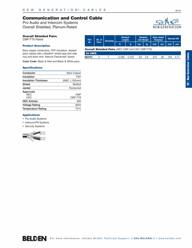
N E W G E N E R A T I O N ® C A B L E S 20.31
20•
New
Gene
ratio
n®Ca
bles
F o r m o r e i n f o r m a t i o n , c o n t a c t B e l d e n Te c h n i c a l S u p p o r t : 1 - 8 0 0 - B E L D E N - 1 • w w w . b e l d e n . c o m
Communication and Control CablePro Audio and Intercom SystemsOverall Shielded, Plenum-Rated
Overall Shielded PairsCMP FT6 Rated
Product Description
Bare copper conductors, FEP insulation, twistedpairs cabled with a Beldfoil® shield tape (foil sideout) and drain wire. Natural Flamarrest® jacket.
Color Code: Black & Red and Black & White pairs.
Specifications
Conductor Bare Copper
Insulation FEP
Insulation Thickness .0060″ (.152mm)
Shield Beldfoil
Jacket Flamarrest
ApprovalsNEC CMPCEC CMP FT6
NEC Articles 800
Voltage Rating 300V
Temperature Rating 75°C
Applications• Pro Audio Systems
• Intercom/PA Systems
• Security Systems
StrandingNo. of Pairs
mFt.
StandardLengths
mmInchkg
Standard Unit Weight
Outer JacketThickness Nominal OD
Inch mmLbs.
PartNo.
Overall Shielded Pairs (NEC CMP and CEC CMP FT6)
24 AWG6641FC 2 7 U-500 U-152 8.0 3.6 .015 .38 .164 4.17
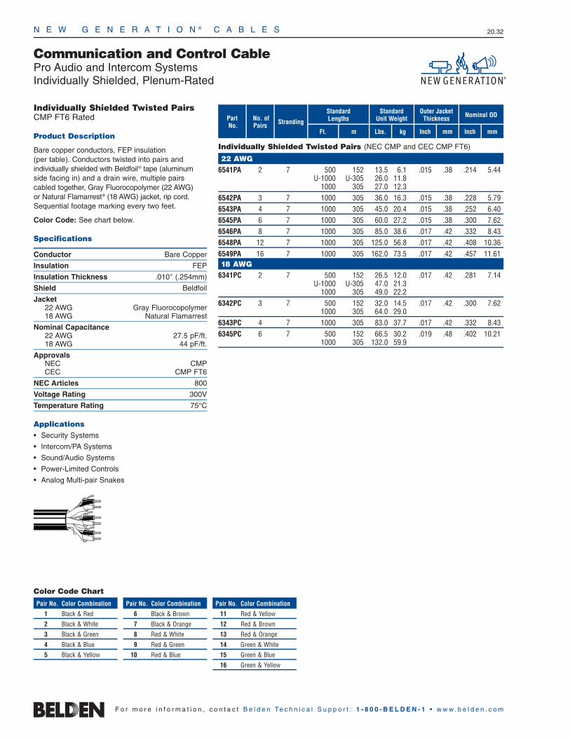
N E W G E N E R A T I O N ® C A B L E S 20.32
F o r m o r e i n f o r m a t i o n , c o n t a c t B e l d e n Te c h n i c a l S u p p o r t : 1 - 8 0 0 - B E L D E N - 1 • w w w . b e l d e n . c o m
StrandingNo. of Pairs
mFt.
StandardLengths
mmInchkg
Standard Unit Weight
Outer JacketThickness Nominal OD
Inch mmLbs.
Communication and Control CablePro Audio and Intercom SystemsIndividually Shielded, Plenum-Rated
PartNo.
Individually Shielded Twisted Pairs (NEC CMP and CEC CMP FT6)
22 AWG6541PA 2 7 500 152 13.5 6.1 .015 .38 .214 5.44
U-1000 U-305 26.0 11.81000 305 27.0 12.3
6542PA 3 7 1000 305 36.0 16.3 .015 .38 .228 5.796543PA 4 7 1000 305 45.0 20.4 .015 .38 .252 6.406545PA 6 7 1000 305 60.0 27.2 .015 .38 .300 7.626546PA 8 7 1000 305 85.0 38.6 .017 .42 .332 8.436548PA 12 7 1000 305 125.0 56.8 .017 .42 .408 10.366549PA 16 7 1000 305 162.0 73.5 .017 .42 .457 11.6118 AWG
6341PC 2 7 500 152 26.5 12.0 .017 .42 .281 7.14U-1000 U-305 47.0 21.3
1000 305 49.0 22.26342PC 3 7 500 152 32.0 14.5 .017 .42 .300 7.62
1000 305 64.0 29.06343PC 4 7 1000 305 83.0 37.7 .017 .42 .332 8.436345PC 6 7 500 152 66.5 30.2 .019 .48 .402 10.21
1000 305 132.0 59.9
Color Code Chart
Pair No. Color Combination
1 Black & Red
2 Black & White
3 Black & Green
4 Black & Blue
5 Black & Yellow
Pair No. Color Combination
6 Black & Brown
7 Black & Orange
8 Red & White
9 Red & Green
10 Red & Blue
Pair No. Color Combination
11 Red & Yellow
12 Red & Brown
13 Red & Orange
14 Green & White
15 Green & Blue
16 Green & Yellow
Individually Shielded Twisted PairsCMP FT6 Rated
Product Description
Bare copper conductors, FEP insulation (per table). Conductors twisted into pairs and individually shielded with Beldfoil® tape (aluminumside facing in) and a drain wire, multiple pairscabled together, Gray Fluorocopolymer (22 AWG) or Natural Flamarrest® (18 AWG) jacket, rip cord.Sequential footage marking every two feet.
Color Code: See chart below.
Specifications
Conductor Bare Copper
Insulation FEP
Insulation Thickness .010″ (.254mm)
Shield Beldfoil
Jacket22 AWG Gray Fluorocopolymer18 AWG Natural Flamarrest
Nominal Capacitance22 AWG 27.5 pF/ft.18 AWG 44 pF/ft.
ApprovalsNEC CMPCEC CMP FT6
NEC Articles 800
Voltage Rating 300V
Temperature Rating 75°C
Applications• Security Systems
• Intercom/PA Systems
• Sound/Audio Systems
• Power-Limited Controls
• Analog Multi-pair Snakes
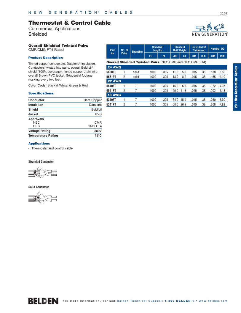
N E W G E N E R A T I O N ® C A B L E S 20.33
StrandingNo. of Pairs
mFt.
StandardLengths
mmInchkg
Standard Unit Weight
Outer JacketThickness Nominal OD
Inch mmLbs.
Thermostat & Control CableCommercial ApplicationsShielded
PartNo.
Overall Shielded Twisted Pairs (NEC CMR and CEC CMG FT4)
24 AWG5660FT 1 solid 1000 305 11.0 5.0 .015 .38 .138 3.505661PT 2 solid 1000 305 18.0 8.2 .015 .38 .165 4.1922 AWG
5540FT 1 7 1000 305 15.0 6.8 .015 .38 .172 4.375541PT 2 7 1000 305 25.0 11.3 .015 .38 .202 5.1318 AWG
5340FT 1 7 1000 305 34.0 15.4 .015 .38 .260 6.605341PT 2 7 1000 305 58.0 26.3 .015 .38 .308 7.82
Overall Shielded Twisted PairsCMR/CMG FT4 Rated
Product Description
Tinned copper conductors, Datalene® insulation.Conductors twisted into pairs, overall Beldfoil®
shield (100% coverage), tinned copper drain wire,overall Brown PVC jacket. Sequential footage marking every two feet.
Color Code: Black & White, Green & Red.
Specifications
Conductor Bare Copper
Insulation Datalene
Shield Beldfoil
Jacket PVC
ApprovalsNEC CMRCEC CMG FT4
Voltage Rating 300V
Temperature Rating 75°C
Applications • Thermostat and control cable
Stranded Conductor
Solid Conductor
20•
New
Gene
ratio
n®Ca
bles
F o r m o r e i n f o r m a t i o n , c o n t a c t B e l d e n Te c h n i c a l S u p p o r t : 1 - 8 0 0 - B E L D E N - 1 • w w w . b e l d e n . c o m
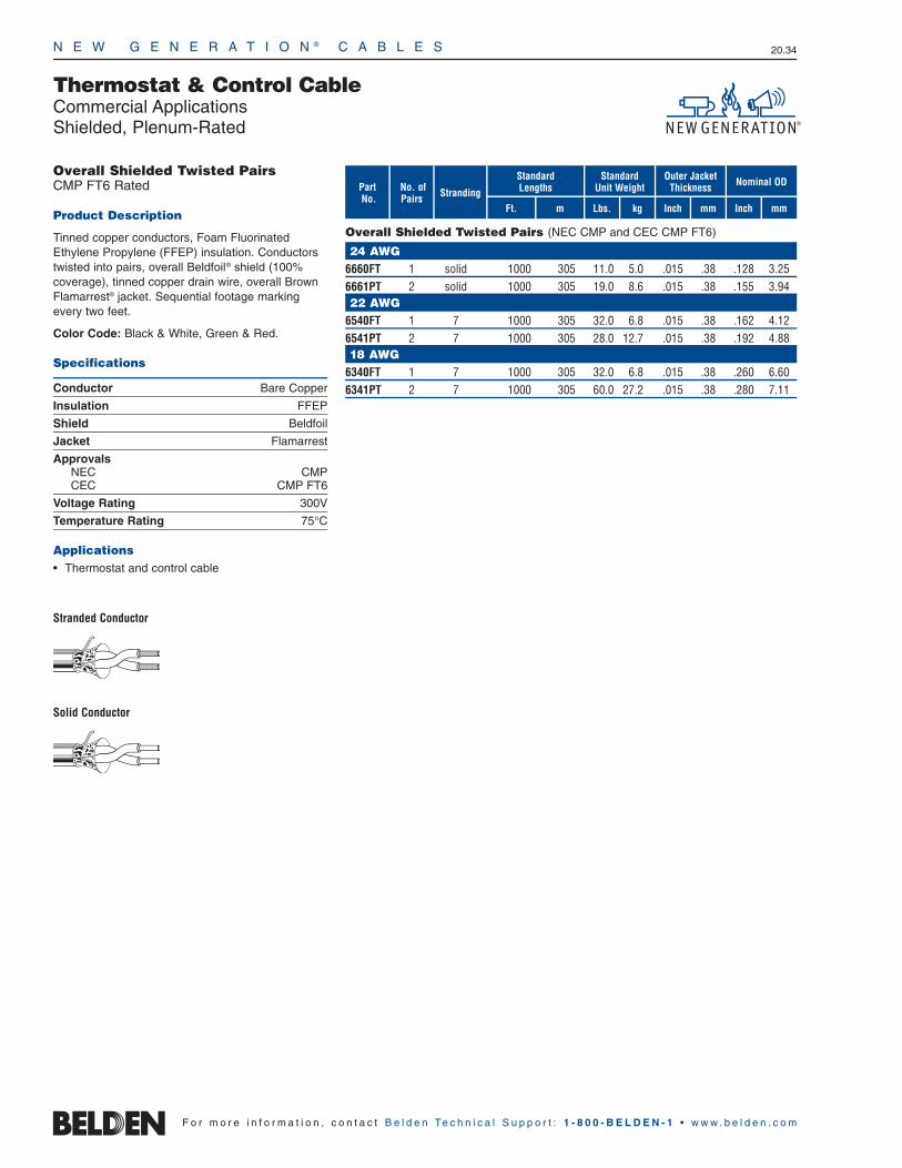
StrandingNo. of Pairs
mFt.
StandardLengths
mmInchkg
Standard Unit Weight
Outer JacketThickness Nominal OD
Inch mmLbs.
N E W G E N E R A T I O N ® C A B L E S 20.34
Thermostat & Control CableCommercial ApplicationsShielded, Plenum-Rated
PartNo.
Overall Shielded Twisted Pairs (NEC CMP and CEC CMP FT6)
24 AWG6660FT 1 solid 1000 305 11.0 5.0 .015 .38 .128 3.256661PT 2 solid 1000 305 19.0 8.6 .015 .38 .155 3.9422 AWG
6540FT 1 7 1000 305 32.0 6.8 .015 .38 .162 4.126541PT 2 7 1000 305 28.0 12.7 .015 .38 .192 4.8818 AWG
6340FT 1 7 1000 305 32.0 6.8 .015 .38 .260 6.606341PT 2 7 1000 305 60.0 27.2 .015 .38 .280 7.11
Overall Shielded Twisted PairsCMP FT6 Rated
Product Description
Tinned copper conductors, Foam FluorinatedEthylene Propylene (FFEP) insulation. Conductorstwisted into pairs, overall Beldfoil® shield (100%coverage), tinned copper drain wire, overall BrownFlamarrest® jacket. Sequential footage markingevery two feet.
Color Code: Black & White, Green & Red.
Specifications
Conductor Bare Copper
Insulation FFEP
Shield Beldfoil
Jacket Flamarrest
ApprovalsNEC CMPCEC CMP FT6
Voltage Rating 300V
Temperature Rating 75°C
Applications • Thermostat and control cable
Stranded Conductor
Solid Conductor
F o r m o r e i n f o r m a t i o n , c o n t a c t B e l d e n Te c h n i c a l S u p p o r t : 1 - 8 0 0 - B E L D E N - 1 • w w w . b e l d e n . c o m
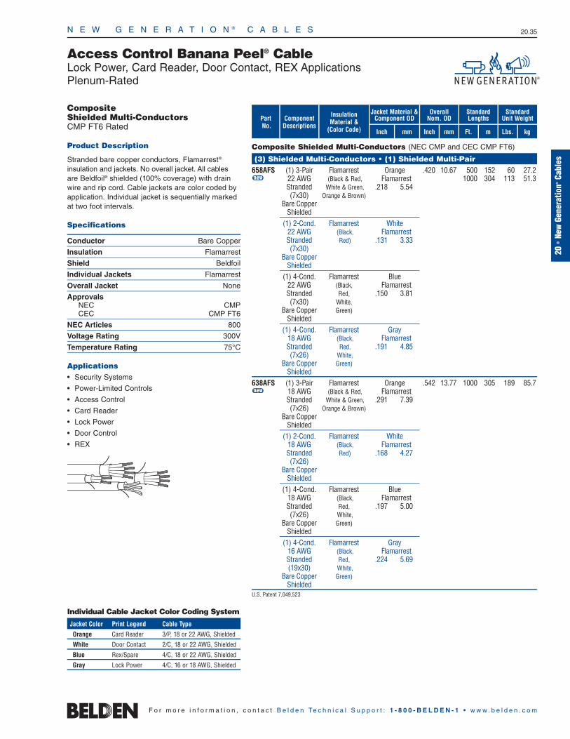
StandardLengths
Ft. m
Overall Nom. OD
Inch mm
N E W G E N E R A T I O N ® C A B L E S 20.35
20•
New
Gene
ratio
n®Ca
bles
Jacket Material & Component OD
Inch mm
Access Control Banana Peel® CableLock Power, Card Reader, Door Contact, REX ApplicationsPlenum-Rated
PartNo.
Composite Shielded Multi-Conductors (NEC CMP and CEC CMP FT6)
(3) Shielded Multi-Conductors • (1) Shielded Multi-Pair658AFS (1) 3-Pair Flamarrest Orange .420 10.67 500 152 60 27.2u 22 AWG (Black & Red, Flamarrest 1000 304 113 51.3
Stranded White & Green, .218 5.54(7x30) Orange & Brown)
Bare CopperShielded
(1) 2-Cond. Flamarrest White22 AWG (Black, FlamarrestStranded Red) .131 3.33(7x30)
Bare CopperShielded
(1) 4-Cond. Flamarrest Blue22 AWG (Black, FlamarrestStranded Red, .150 3.81(7x30) White,
Bare Copper Green)Shielded
(1) 4-Cond. Flamarrest Gray18 AWG (Black, FlamarrestStranded Red, .191 4.85(7x26) White,
Bare Copper Green)Shielded
638AFS (1) 3-Pair Flamarrest Orange .542 13.77 1000 305 189 85.7u 18 AWG (Black & Red, Flamarrest
Stranded White & Green, .291 7.39(7x26) Orange & Brown)
Bare CopperShielded
(1) 2-Cond. Flamarrest White18 AWG (Black, FlamarrestStranded Red) .168 4.27(7x26)
Bare CopperShielded
(1) 4-Cond. Flamarrest Blue18 AWG (Black, FlamarrestStranded Red, .197 5.00(7x26) White,
Bare Copper Green)Shielded
(1) 4-Cond. Flamarrest Gray16 AWG (Black, FlamarrestStranded Red, .224 5.69(19x30) White,
Bare Copper Green)Shielded
U.S. Patent 7,049,523
ComponentDescriptions
InsulationMaterial &
(Color Code)
StandardUnit Weight
Lbs. kg
CompositeShielded Multi-ConductorsCMP FT6 Rated
Product Description
Stranded bare copper conductors, Flamarrest®
insulation and jackets. No overall jacket. All cablesare Beldfoil® shielded (100% coverage) with drainwire and rip cord. Cable jackets are color coded byapplication. Individual jacket is sequentially markedat two foot intervals.
Specifications
Conductor Bare Copper
Insulation Flamarrest
Shield Beldfoil
Individual Jackets Flamarrest
Overall Jacket None
ApprovalsNEC CMPCEC CMP FT6
NEC Articles 800
Voltage Rating 300V
Temperature Rating 75°C
Applications• Security Systems
• Power-Limited Controls
• Access Control
• Card Reader
• Lock Power
• Door Control
• REX
Individual Cable Jacket Color Coding System
Jacket Color Print Legend Cable Type
Orange Card Reader 3/P, 18 or 22 AWG, Shielded
White Door Contact 2/C, 18 or 22 AWG, Shielded
Blue Rex/Spare 4/C, 18 or 22 AWG, Shielded
Gray Lock Power 4/C, 16 or 18 AWG, Shielded
F o r m o r e i n f o r m a t i o n , c o n t a c t B e l d e n Te c h n i c a l S u p p o r t : 1 - 8 0 0 - B E L D E N - 1 • w w w . b e l d e n . c o m

N E W G E N E R A T I O N ® C A B L E S 20.36
Access Control Banana Peel® CableLock Power, Card Reader, Door Contact, REX ApplicationsRiser-Rated
Composite Shielded Multi-Conductors (NEC CMR and CEC CMG)
(3) Shielded Multi-Conductors • (1) Shielded Multi-Pair558AFS (1) 3-Pair F-R PVC Orange .448 11.38 500 152 59 26.5u 22 AWG (Black & Red, FR-PVC 1000 305 108 49.0
Stranded White & Green, .233 5.92(7x30) Orange & Brown)
Bare CopperShielded
(1) 2-Cond. F-R PVC White22 AWG (Black, FR-PVCStranded Red) .140 3.56(7x30)
Bare CopperShielded
(1) 4-Cond. F-R PVC Blue22 AWG (Black, FR-PVCStranded Red, .161 4.09(7x30) White,
Bare Copper Green)Shielded
(1) 4-Cond. F-R PVC Gray18 AWG (Black, FR-PVCStranded Red, .202 5.13(7x26) White,
Bare Copper Green)Shielded
538AFS (1) 3-Pair PVC Orange .516 13.11 1000 305 182 82.6u 18 AWG (Black & Red, PVC
Stranded White & Green, .285 7.24(7x26) Orange & Brown)
Bare CopperShielded
(1) 2-Cond. PVC White18 AWG (Black, PVCStranded Red) .175 4.45(7x26)
Bare CopperShielded
(1) 4-Cond. PVC Blue18 AWG (Black, PVCStranded Red, .202 5.13(7x26) White,
Bare Copper Green)Shielded
(1) 4-Cond. PVC Gray16 AWG (Black, PVCStranded Red, .230 5.84(19x30) White,
Bare Copper Green)Shielded
F-R = Flame-retardant
U.S. Patent 7,049,523
F o r m o r e i n f o r m a t i o n , c o n t a c t B e l d e n Te c h n i c a l S u p p o r t : 1 - 8 0 0 - B E L D E N - 1 • w w w . b e l d e n . c o m
CompositeShielded Multi-ConductorsCMR/CMG Rated
Product Description
Stranded bare copper conductors, PVC or Flame-retardant PVC insulation and jackets. No overall jacket. All cables are Beldfoil® shielded(100% coverage) with drain wire and rip cord. Cablejackets are color coded by application. Individualjacket is sequentially marked at two foot intervals.
Specifications
Conductor Bare Copper
Insulation PVC or FR-PVC
Shield Beldfoil
Individual Jackets PVC or FR-PVC
Overall Jacket None
ApprovalsNEC CMRCEC CMG
NEC Articles 800
Voltage Rating 300V
Temperature Rating 75°C
Applications • Security Systems
• Power-Limited Controls
• Access Control
• Card Reader
• Lock Power
• Door Control
• REX
Individual Cable Jacket Color Coding System
Jacket Color Print Legend Cable Type
Orange Card Reader 3/P, 18 or 22 AWG, Shielded
White Door Contact 2/C, 18 or 22 AWG, Shielded
Blue Rex/Spare 4/C, 18 or 22 AWG, Shielded
Gray Lock Power 4/C, 16 or 18 AWG, Shielded
StandardLengths
Ft. m
Overall Nom. OD
Inch mm
Jacket Material & Component OD
Inch mm
PartNo.
ComponentDescriptions
InsulationMaterial &
(Color Code)
StandardUnit Weight
Lbs. kg
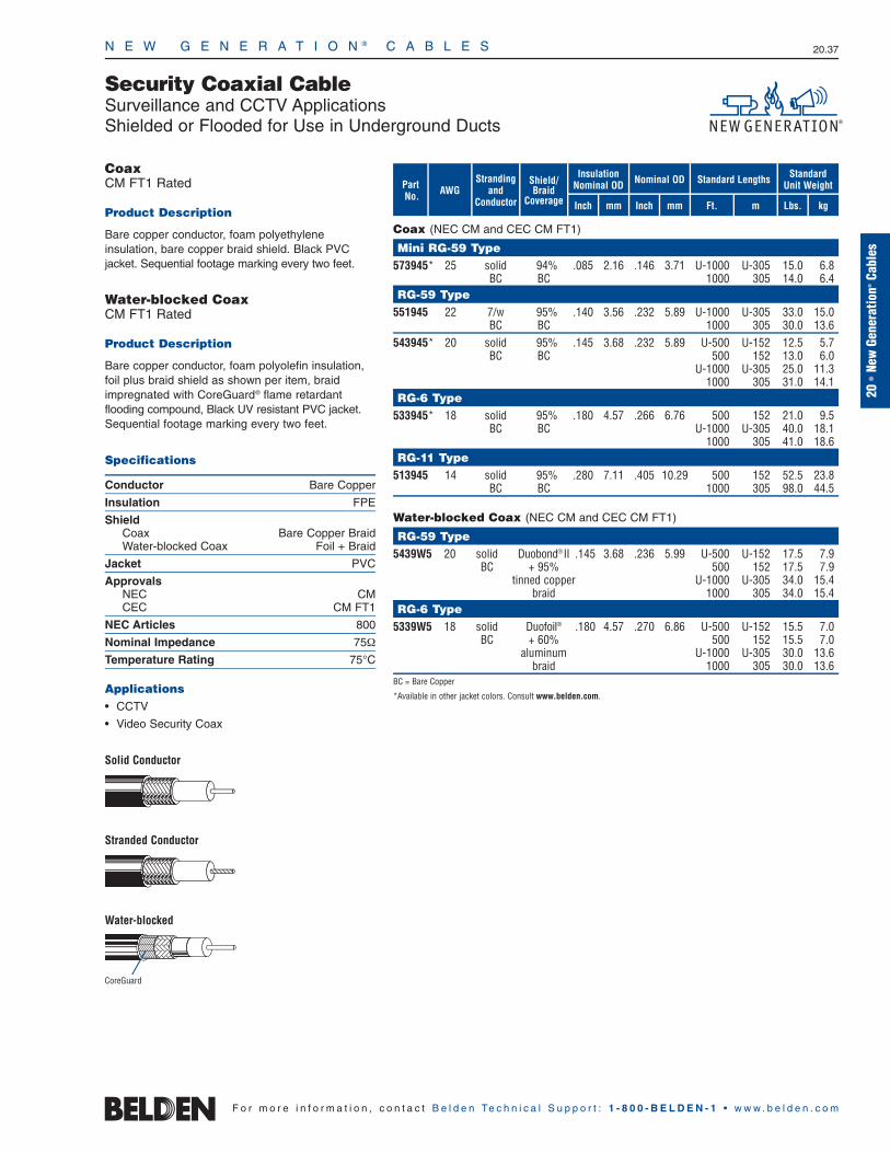
N E W G E N E R A T I O N ® C A B L E S 20.37
20•
New
Gene
ratio
n®Ca
bles
F o r m o r e i n f o r m a t i o n , c o n t a c t B e l d e n Te c h n i c a l S u p p o r t : 1 - 8 0 0 - B E L D E N - 1 • w w w . b e l d e n . c o m
Security Coaxial CableSurveillance and CCTV ApplicationsShielded or Flooded for Use in Underground Ducts
Coax (NEC CM and CEC CM FT1)
Mini RG-59 Type573945* 25 solid 94% .085 2.16 .146 3.71 U-1000 U-305 15.0 6.8
BC BC 1000 305 14.0 6.4RG-59 Type
551945 22 7/w 95% .140 3.56 .232 5.89 U-1000 U-305 33.0 15.0BC BC 1000 305 30.0 13.6
543945* 20 solid 95% .145 3.68 .232 5.89 U-500 U-152 12.5 5.7BC BC 500 152 13.0 6.0
U-1000 U-305 25.0 11.31000 305 31.0 14.1
RG-6 Type533945* 18 solid 95% .180 4.57 .266 6.76 500 152 21.0 9.5
BC BC U-1000 U-305 40.0 18.11000 305 41.0 18.6
RG-11 Type513945 14 solid 95% .280 7.11 .405 10.29 500 152 52.5 23.8
BC BC 1000 305 98.0 44.5
Water-blocked Coax (NEC CM and CEC CM FT1)
RG-59 Type5439W5 20 solid Duobond®II .145 3.68 .236 5.99 U-500 U-152 17.5 7.9
BC + 95% 500 152 17.5 7.9tinned copper U-1000 U-305 34.0 15.4
braid 1000 305 34.0 15.4RG-6 Type
5339W5 18 solid Duofoil® .180 4.57 .270 6.86 U-500 U-152 15.5 7.0BC + 60% 500 152 15.5 7.0
aluminum U-1000 U-305 30.0 13.6braid 1000 305 30.0 13.6
BC = Bare Copper
*Available in other jacket colors. Consult www.belden.com.
Shield/Braid
Coverage
Strandingand
ConductorAWGPart
No.mFt.
Standard Lengths
mmInch kg
Standard Unit Weight
InsulationNominal OD Nominal OD
Inch mm Lbs.
CoreGuard
CoaxCM FT1 Rated
Product Description
Bare copper conductor, foam polyethylene insulation, bare copper braid shield. Black PVCjacket. Sequential footage marking every two feet.
Water-blocked CoaxCM FT1 Rated
Product Description
Bare copper conductor, foam polyolefin insulation,foil plus braid shield as shown per item, braidimpregnated with CoreGuard® flame retardant flooding compound, Black UV resistant PVC jacket.Sequential footage marking every two feet.
Specifications
Conductor Bare Copper
Insulation FPE
ShieldCoax Bare Copper BraidWater-blocked Coax Foil + Braid
Jacket PVC
ApprovalsNEC CMCEC CM FT1
NEC Articles 800
Nominal Impedance 75Ω
Temperature Rating 75°C
Applications• CCTV
• Video Security Coax
Solid Conductor
Stranded Conductor
Water-blocked

N E W G E N E R A T I O N ® C A B L E S 20.38
F o r m o r e i n f o r m a t i o n , c o n t a c t B e l d e n Te c h n i c a l S u p p o r t : 1 - 8 0 0 - B E L D E N - 1 • w w w . b e l d e n . c o m
Security Composite CableCCTV plus Audio or Power or Pan and Tilt CCTV Control ApplicationsPlenum-Rated and Non-Plenum
Shield/Braid
Coverage
Strandingand
ConductorAWGPart
No.
CM-Rated Composite (NEC CM and CEC CM FT1)
Mini RG-59 Type579945 25(cx) solid BC 95% BC .085 2.16 .151 3.84 500 152 15.0 6.8u 20(pr) 7/w BC unshielded .056 1.42 x x 1000 305 29.0 13.2
.332 8.43RG-59 Type
549945 20(cx) solid BC 95% BC .145 3.68 .232 5.89 500 152 30.0 13.618(pr) 7/w BC unshielded .066 1.68 x x 1000 305 60.0 27.3
.460 11.68RG-6 Type
539945 18(cx) solid BC 95% BC .180 4.57 .266 6.76 500 152 34.0 15.518(pr) 7/w BC unshielded .066 1.68 x x 1000 305 69.0 31.3
.500 12.70
CMG-LS -Rated Composite (NEC CMG-LS and CEC CMG-LS FT4 Limited Smoke)
RG-6 Type1306SB 18(cx) solid BC 95% BC .180 4.57 .275 6.99 500 152 37.0 16.8u 18(pr) 7/w BC unshielded .059 1.59 x x 1000 305 76.0 34.5
.514 13.06
Plenum-Rated Composite (NEC CMP and CEC CMP FT6)
Mini RG-59 Type679948* 25(cx) solid BC 95% BC .078 1.98 .144 3.66 500 152 16.5 7.4u 20(pr) 7/w BC unshielded .048 1.22 x x 1000 305 34.0 15.5
.328 8.33RG-59 Type
649948 20(cx) solid BC 95% BC .134 3.40 .199 5.05 500 152 29.0 13.218(pr) 7/w BC unshielded .059 1.50 x x 1000 305 54.0 24.5
.383 9.72RG-6 Type
639948 18(cx) solid BC 95% BC .170 4.32 .232 5.89 500 152 32.0 14.518(pr) 7/w BC unshielded .059 1.50 x x 1000 305 60.0 27.2
.416 10.57BC = Bare Copper • cx = Coax • pr = Pair • LSZH = Low-Smoke, Zero-Halogen
*679948 also available in White.
mFt.
Standard Lengths
mmInch kg
Standard Unit Weight
InsulationNominal OD Nominal OD
Inch mm Lbs.
Non-Plenum Composite Coax plus Twisted PairCM FT1 or CMG-LS FT4 Rated
Product DescriptionCoax: Solid bare copper conductor, foam polyolefin insulation, bare copper braid shield. Black PVC jacket(1306SB has Black LSZH jacket).
Pair: Stranded bare copper conductor, PVC insulation, Black PVC jacket. (1306SB haspolypropylene insulation. Black LSZH jacket.) Color coded: Black & Red.
Plenum-Rated CompositeCoax plus Twisted PairCMP FT6 Rated
Product DescriptionCoax: Solid bare copper conductor, FEP insulation,bare copper braid shield, Natural Flamarrest® jacket.
Pair: Stranded FEP insulation, Natural Flamarrestjacket.Color coded: Black & Red.
Coax and pair in Siamese configuration. Sequential footage marking every two feet.
Specifications
Conductor Bare Copper
Insulation (Non-Plenum)Coax FPOPair PVC
Insulation (Plenum) FEP
Shield (Coax) Bare Copper Braid
JacketNon-Plenum PVCPlenum Flamarrest
Approvals (Non-Plenum)NEC CM CEC CM FT1
Approvals (LSZH)NEC CMG-LS CEC CMG-LS FT4 Limited Smoke
Approvals (Plenum)NEC CMPCEC CMP FT6
NEC Articles 800
Nominal Impedance (Coax) 75Ω
Temperature Rating 75°C
Applications• CCTV plus Audio or Power
• Pan, Tilt and Zoom CCTV Control
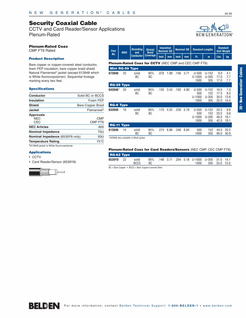
N E W G E N E R A T I O N ® C A B L E S 20.39
20•
New
Gene
ratio
n®Ca
bles
F o r m o r e i n f o r m a t i o n , c o n t a c t B e l d e n Te c h n i c a l S u p p o r t : 1 - 8 0 0 - B E L D E N - 1 • w w w . b e l d e n . c o m
Security Coaxial CableCCTV and Card Reader/Sensor ApplicationsPlenum-Rated
Plenum-Rated Coax for CCTV (NEC CMP and CEC CMP FT6)
Mini RG-59 Type673948 25 solid 95% .078 1.98 .146 3.71 U-500 U-152 9.0 4.1
BC BC U-1000 U-305 17.0 7.71000 305 17.0 7.7
RG-59 Type643948* 20 solid 95% .135 3.43 .193 4.90 U-500 U-152 16.0 7.3
BC BC 500 152 17.5 8.0U-1000 U-305 30.0 13.6
1000 305 32.0 14.5RG-6 Type
633948 18 solid 95% .170 4.32 .228 5.79 U-500 U-152 20.5 9.8BC BC 500 152 20.5 9.8
U-1000 U-305 40.0 18.11000 305 42.0 19.1
RG-11 Type613948 14 solid 95% .274 6.96 .348 8.84 500 152 44.5 20.2
BC BC 1000 305 90.0 40.9*643948 also available in Black jacket.
Plenum-Rated Coax for Card Readers/Sensors (NEC CMP, CEC CMP FT6)
RG-62 Type6539Y8 22 solid 95% .146 3.71 .204 5.18 U-1000 U-305 31.0 14.1
BCCS BC 1000 305 33.0 15.0BC = Bare Copper • BCCS = Bare Copper-covered Steel
Shield/Braid
Coverage
Strandingand
ConductorAWGPart
No.mFt.
Standard Lengths
mmInch kg
Standard Unit Weight
InsulationNominal OD Nominal OD
Inch mm Lbs.
Plenum-Rated CoaxCMP FT6 Rated
Product Description
Bare copper or copper-covered steel conductor,foam FEP insulation, bare copper braid shield. Natural Flamarrest® jacket (except 613948 which is White fluorocopolymer). Sequential footage marking every two feet.
Specifications
Conductor Solid BC or BCCS
Insulation Foam FEP
Shield Bare Copper Braid
Jacket Flamarrest†
ApprovalsNEC CMPCEC CMP FT6
NEC Articles 800
Nominal Impedance 75Ω
Nominal Impedance (6539Y8 only) 93Ω
Temperature Rating 75°C†613948 jacket is White fluorocopolymer.
Applications• CCTV
• Card Reader/Sensor (6539Y8)
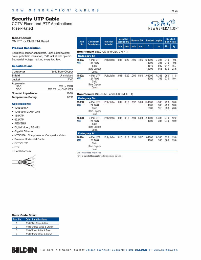
Security UTP CableCCTV Fixed and PTZ ApplicationsRiser-Rated
N E W G E N E R A T I O N ® C A B L E S 20.40
F o r m o r e i n f o r m a t i o n , c o n t a c t B e l d e n Te c h n i c a l S u p p o r t : 1 - 8 0 0 - B E L D E N - 1 • w w w . b e l d e n . c o m
Non-PlenumCM FT1 or CMR FT4 Rated
Product Description
Solid bare copper conductors, unshielded twistedpairs, polyolefin insulation, PVC jacket with rip cord.Sequential footage marking every two feet.
Specifications
Conductor Solid Bare Copper
Shield Unshielded
Jacket PVC
ApprovalsNEC CM or CMRCEC CM FT1 or CMR FT4
Nominal Impedance 100Ω
Temperature Rating 80°C
Applications: • 100BaseTX
• 100BaseVG ANYLAN
• 155ATM
• 622ATM
• AES/EBU
• Digital Video, RS-422
• Gigabit Ethernet
• NTSC/PAL Component or Composite Video
• Premise Horizontal Cable
• CCTV UTP
• PTZ
• Pan/Tilt/Zoom
Non-Plenum (NEC CM and CEC CM FT1)
Category 5e1583A 4-Pair UTP Polyolefin .008 0.20 .195 4.95 U-1000 U-305 21.0 9.5u 24 AWG 1000 305 21.0 9.5
Solid 1640 500 34.4 15.7Bare Copper 3000 915 63.0 28.6
Cond.1500A 4-Pair UTP Polyolefin .008 0.20 .200 5.08 A-1000 A-305 26.0 11.8u 24 AWG 1000 305 23.0 10.4
SolidBare Copper
Cond.
Non-Plenum (NEC CMR and CEC CMR FT4)
Category 5e1583R 4-Pair UTP Polyolefin .007 0.18 .197 5.00 U-1000 U-305 22.0 10.0u 24 AWG 1000 305 22.0 10.0
Solid 3000 915 63.0 28.6Bare Copper
Cond.1500R 4-Pair UTP Polyolefin .007 0.18 .194 5.00 A-1000 A-305 27.0 12.2u 24 AWG 1000 305 24.0 10.9
SolidBare Copper
Cond.Category 6
7881A 4-Pair UTP Polyolefin .010 0.18 .235 5.97 A-1000 A-305 33.0 15.0u 23 AWG 1000 305 30.0 13.6
SolidBare Copper
Cond.UTP = Unshielded Twisted Pair
Refer to www.belden.com for jacket colors and put-ups.
mFt.
Standard Lengths
mmInch kg
Standard Unit Weight
InsulationNominal OD Nominal OD
Inch mm Lbs.
PartNo.
ComponentDescriptions
InsulationMaterial
Color Code Chart
Pair No. Color Combinations1 White/Blue Stripe & Blue
2 White/Orange Stripe & Orange
3 White/Green Stripe & Green
4 White/Brown Stripe & Brown
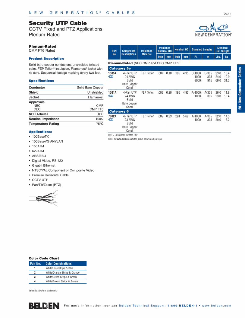
N E W G E N E R A T I O N ® C A B L E S 20.41
Security UTP CableCCTV Fixed and PTZ ApplicationsPlenum-Rated
20•
New
Gene
ratio
n®Ca
bles
F o r m o r e i n f o r m a t i o n , c o n t a c t B e l d e n Te c h n i c a l S u p p o r t : 1 - 8 0 0 - B E L D E N - 1 • w w w . b e l d e n . c o m
Plenum-RatedCMP FT6 Rated
Product Description
Solid bare copper conductors, unshielded twistedpairs, FEP Teflon® insulation, Flamarrest® jacket withrip cord. Sequential footage marking every two feet.
Specifications
Conductor Solid Bare Copper
Shield Unshielded
Jacket Flamarrest
ApprovalsNEC CMPCEC CMP FT6
NEC Articles 800
Nominal Impedance 100Ω
Temperature Rating 75°C
Applications: • 100BaseTX
• 100BaseVG ANYLAN
• 155ATM
• 622ATM
• AES/EBU
• Digital Video, RS-422
• Gigabit Ethernet
• NTSC/PAL Component or Composite Video
• Premise Horizontal Cable
• CCTV UTP
• Pan/Tilt/Zoom (PTZ)
Plenum-Rated (NEC CMP and CEC CMP FT6)
Category 5e1585A 4-Pair UTP FEP Teflon .007 0.18 .195 4.95 U-1000 U-305 23.0 10.4u 24 AWG 1000 305 24.0 10.9
Solid 3000 915 69.0 31.3Bare Copper
Cond.1501A 4-Pair UTP FEP Teflon .008 0.20 .195 4.95 A-1000 A-305 26.0 11.8u 24 AWG 1000 305 23.0 10.4
SolidBare Copper
Cond.Category 6
7882A 4-Pair UTP FEP Teflon .009 0.23 .224 5.69 A-1000 A-305 32.0 14.5u 23 AWG 1000 305 29.0 13.2
SolidBare Copper
Cond.UTP = Unshielded Twisted Pair
Refer to www.belden.com for jacket colors and put-ups.
mFt.
Standard Lengths
mmInch kg
Standard Unit Weight
InsulationNominal OD Nominal OD
Inch mm Lbs.
PartNo.
ComponentDescriptions
InsulationMaterial
Teflon is a DuPont trademark.
Color Code Chart
Pair No. Color Combinations1 White/Blue Stripe & Blue
2 White/Orange Stripe & Orange
3 White/Green Stripe & Green
4 White/Brown Stripe & Brown
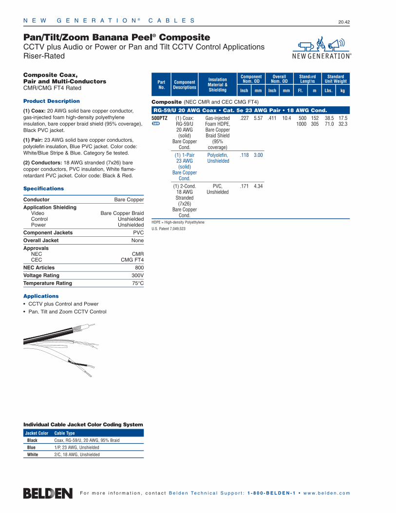
N E W G E N E R A T I O N ® C A B L E S 20.42
F o r m o r e i n f o r m a t i o n , c o n t a c t B e l d e n Te c h n i c a l S u p p o r t : 1 - 8 0 0 - B E L D E N - 1 • w w w . b e l d e n . c o m
Component Nom. OD
Overall Nom. OD
StandardLengths
Inch mm
Pan/Tilt/Zoom Banana Peel® CompositeCCTV plus Audio or Power or Pan and Tilt CCTV Control ApplicationsRiser-Rated
PartNo.
Composite (NEC CMR and CEC CMG FT4)
RG-59/U 20 AWG Coax • Cat. 5e 23 AWG Pair • 18 AWG Cond.500PTZ (1) Coax: Gas-injected .227 5.57 .411 10.4 500 152 38.5 17.5u RG-59/U Foam HDPE, 1000 305 71.0 32.3
20 AWG Bare Copper(solid) Braid Shield
Bare Copper (95% Cond. coverage)
(1) 1-Pair Polyolefin, .118 3.0023 AWG Unshielded(solid)
Bare CopperCond.
(1) 2-Cond. PVC, .171 4.3418 AWG UnshieldedStranded(7x26)
Bare CopperCond.
HDPE = High-density Polyethylene
U.S. Patent 7,049,523
Inch mm
ComponentDescriptions
InsulationMaterial &Shielding
StandardUnit Weight
Lbs. kgFt. m
Composite Coax,Pair and Multi-ConductorsCMR/CMG FT4 Rated
Product Description
(1) Coax: 20 AWG solid bare copper conductor,gas-injected foam high-density polyethylene insulation, bare copper braid shield (95% coverage),Black PVC jacket.
(1) Pair: 23 AWG solid bare copper conductors, polyolefin insulation, Blue PVC jacket. Color code:White/Blue Stripe & Blue. Category 5e tested.
(2) Conductors: 18 AWG stranded (7x26) barecopper conductors, PVC insulation, White flame-retardant PVC jacket. Color code: Black & Red.
Specifications
Conductor Bare Copper
Application ShieldingVideo Bare Copper BraidControl UnshieldedPower Unshielded
Component Jackets PVC
Overall Jacket None
ApprovalsNEC CMRCEC CMG FT4
NEC Articles 800
Voltage Rating 300V
Temperature Rating 75°C
Applications • CCTV plus Control and Power
• Pan, Tilt and Zoom CCTV Control
Individual Cable Jacket Color Coding System
Jacket Color Cable Type
Black Coax, RG-59/U, 20 AWG, 95% Braid
Blue 1/P, 23 AWG, Unshielded
White 2/C, 18 AWG, Unshielded

Composite Coax, Pair and Multi-ConductorsCMP FT6 Rated
Product Description
(1) Coax: 20 AWG solid bare copper conductor, FoamPerfluoroalkoxy (FPFA) insulation, bare copper braidshield (95% coverage), Black Flamarrest® jacket.
(1) Pair: 23 AWG solid bare copper conductors, FEP insulation, Blue Flamarrest jacket. Color code:White/Blue Stripe & Blue. Category 5e tested.
(2) Conductors: 18 AWG stranded (7x26) barecopper conductors, Flamarrest insulation, WhiteFlamarrest jacket. Color code: Black & Red.
Specifications
Conductor Bare Copper
Application ShieldingVideo Bare Copper BraidControl UnshieldedPower Unshielded
Component Jackets Flamarrest
Overall Jacket None
ApprovalsNEC CMPCEC CMP FT6
NEC Articles 800
Voltage Rating 300V
Temperature Rating 75°C
Applications • CCTV plus Control and Power
• Pan, Tilt and Zoom CCTV Control
N E W G E N E R A T I O N ® C A B L E S 20.43
20•
New
Gene
ratio
n®Ca
bles
F o r m o r e i n f o r m a t i o n , c o n t a c t B e l d e n Te c h n i c a l S u p p o r t : 1 - 8 0 0 - B E L D E N - 1 • w w w . b e l d e n . c o m
Pan/Tilt/Zoom Banana Peel® CompositeCCTV plus Audio or Power or Pan and Tilt CCTV Control ApplicationsPlenum-Rated
Component Nom. OD
Overall Nom. OD
StandardLengths
Inch mm
PartNo.
Plenum-rated Composite (NEC CMP and CEC CMP FT6)
RG-59/U 20 AWG Coax • Cat. 5e 23 AWG Pair • 18 AWG Cond.600PTZ (1) Coax: FPFA, .193 4.90 .351 8.9 500 152 38.5 17.5u RG-59/U Bare Copper 1000 305 71.0 32.2
20 AWG Braid Shield(solid) (95%
Bare Copper coverage)Cond.
(1) 1-Pair FEP, .116 2.9523 AWG Unshielded(solid)
Bare CopperCond.
(1) 2-Cond. Flamarrest, .158 4.0118 AWG Unshielded Stranded(7x26)
Bare CopperCond.
FEP = Fluorinated Ethylene Propylene • FPFA = Foam Perfluoroalkoxy
U.S. Patent 7,049,523
Inch mm
ComponentDescriptions
InsulationMaterial &Shielding
StandardUnit Weight
Lbs. kgFt. m
Individual Cable Jacket Color Coding System
Jacket Color Cable Type
Black Coax, RG-59/U, 20 AWG, BC Braid (95%)
Blue 1/P, 23 AWG, Unshielded
White 2/C, 18 AWG, Unshielded

N E W G E N E R A T I O N ® C A B L E S 20.44
F o r m o r e i n f o r m a t i o n , c o n t a c t B e l d e n Te c h n i c a l S u p p o r t : 1 - 8 0 0 - B E L D E N - 1 • w w w . b e l d e n . c o m
Component Nom. OD
Overall Nom. OD
StandardLengths
Inch mm
Pan/Tilt/Zoom Banana Peel® CompositeCCTV plus Audio or Power or Pan and Tilt CCTV Control ApplicationsRiser-Rated
PartNo.
Composite (NEC CMR and CEC CMG FT4)
RG-59/U 20 AWG Coax • Cat. 5e 22 AWG Pair • 18 AWG Cond.501PTZ (1) Coax: Gas-injected .227 5.57 .419 10.6 500 152 41.0 18.6u RG-59/U Foam HDPE, 1000 305 76.0 34.5
20 AWG BC Braid (solid) Shield
BC (95% Cond. coverage)
(1) 1-Pair Polyolefin, .177 4.5022 AWG Beldfoil(7x30) Shield
BC (100%Cond. coverage)
(1) 2-Cond. PVC, .171 4.3418 AWG UnshieldedStranded(7x26)
BCCond.
BC = Bare Copper • HDPE = High-density Polyethylene
U.S. Patent 7,049,523
Inch mm
ComponentDescriptions
InsulationMaterial &Shielding
StandardUnit Weight
Lbs. kgFt. m
Individual Cable Jacket Color Coding System
Jacket Color Cable Type
Black Coax: RG-59/U, 20 AWG, BC Braid Shield
Blue 1/P, 22 AWG, Beldfoil Shield
White 2/C, 18 AWG, Unshielded
Composite Coax, Pair and Multi-ConductorsCMR/CMG FT4 Rated
Product Description
(1) Coax: 20 AWG solid bare copper conductor,gas-injected foam high-density polyethylene insulation, bare copper braid shield (95% coverage),Black PVC jacket.
(1) Pair: 22 AWG stranded (7x30) bare copper conductors, polyolefin insulation, Beldfoil® shield(100% coverage), Blue PVC jacket. Color code:White/Blue Stripe & Blue. Category 5e tested.
(2) Conductors: 18 AWG stranded (7x26) barecopper conductors, PVC insulation, White flame-retardant PVC jacket. Color code: Black & Red.
Specifications
Conductor Bare Copper
Application ShieldingVideo Bare Copper BraidControl Aluminum/PolyesterPower Unshielded
Component Jackets PVC
Overall Jacket None
ApprovalsNEC CMRCEC CMG FT4
NEC Articles 800
Voltage Rating 300V
Temperature Rating 75°C
Applications • CCTV plus Control and Power
• Pan, Tilt and Zoom CCTV Control
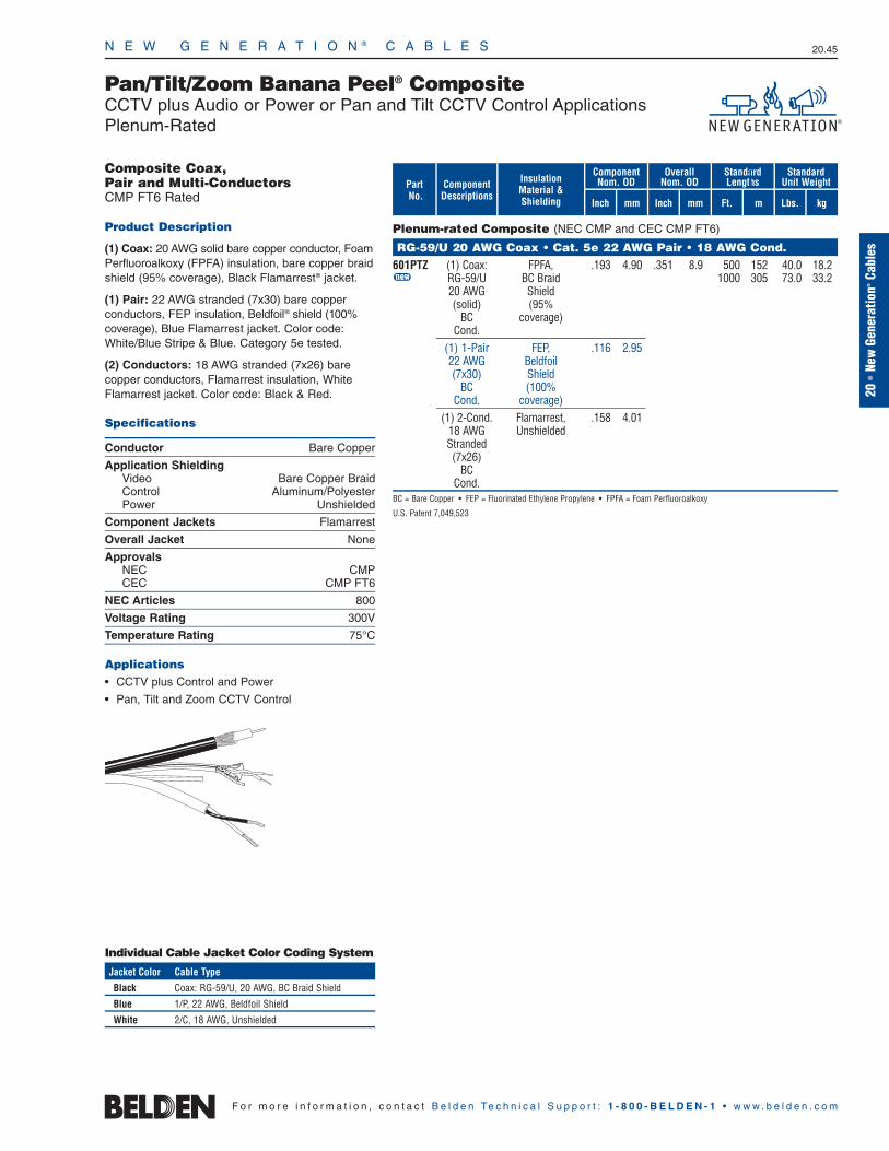
N E W G E N E R A T I O N ® C A B L E S 20.45
20•
New
Gene
ratio
n®Ca
bles
F o r m o r e i n f o r m a t i o n , c o n t a c t B e l d e n Te c h n i c a l S u p p o r t : 1 - 8 0 0 - B E L D E N - 1 • w w w . b e l d e n . c o m
Pan/Tilt/Zoom Banana Peel® CompositeCCTV plus Audio or Power or Pan and Tilt CCTV Control ApplicationsPlenum-Rated
Component Nom. OD
Overall Nom. OD
StandardLengths
Inch mm
PartNo.
Plenum-rated Composite (NEC CMP and CEC CMP FT6)
RG-59/U 20 AWG Coax • Cat. 5e 22 AWG Pair • 18 AWG Cond.601PTZ (1) Coax: FPFA, .193 4.90 .351 8.9 500 152 40.0 18.2u RG-59/U BC Braid 1000 305 73.0 33.2
20 AWG Shield(solid) (95%
BC coverage)Cond.
(1) 1-Pair FEP, .116 2.9522 AWG Beldfoil(7x30) Shield
BC (100%Cond. coverage)
(1) 2-Cond. Flamarrest, .158 4.0118 AWG Unshielded Stranded(7x26)
BCCond.
BC = Bare Copper • FEP = Fluorinated Ethylene Propylene • FPFA = Foam Perfluoroalkoxy
U.S. Patent 7,049,523
Inch mm
ComponentDescriptions
InsulationMaterial &Shielding
StandardUnit Weight
Lbs. kgFt. m
Composite Coax, Pair and Multi-ConductorsCMP FT6 Rated
Product Description
(1) Coax: 20 AWG solid bare copper conductor, FoamPerfluoroalkoxy (FPFA) insulation, bare copper braidshield (95% coverage), Black Flamarrest® jacket.
(1) Pair: 22 AWG stranded (7x30) bare copper conductors, FEP insulation, Beldfoil® shield (100%coverage), Blue Flamarrest jacket. Color code:White/Blue Stripe & Blue. Category 5e tested.
(2) Conductors: 18 AWG stranded (7x26) barecopper conductors, Flamarrest insulation, WhiteFlamarrest jacket. Color code: Black & Red.
Specifications
Conductor Bare Copper
Application ShieldingVideo Bare Copper BraidControl Aluminum/PolyesterPower Unshielded
Component Jackets Flamarrest
Overall Jacket None
ApprovalsNEC CMPCEC CMP FT6
NEC Articles 800
Voltage Rating 300V
Temperature Rating 75°C
Applications • CCTV plus Control and Power
• Pan, Tilt and Zoom CCTV Control
Individual Cable Jacket Color Coding System
Jacket Color Cable Type
Black Coax: RG-59/U, 20 AWG, BC Braid Shield
Blue 1/P, 22 AWG, Beldfoil Shield
White 2/C, 18 AWG, Unshielded
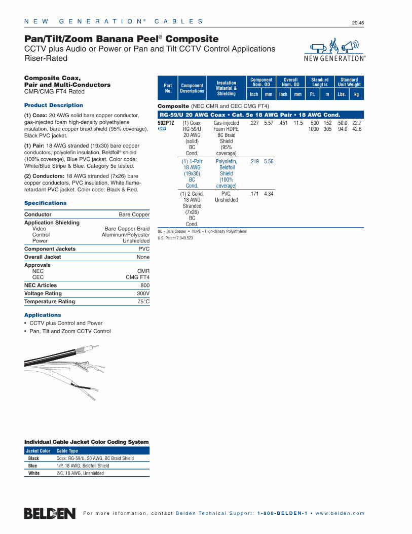
N E W G E N E R A T I O N ® C A B L E S 20.46
F o r m o r e i n f o r m a t i o n , c o n t a c t B e l d e n Te c h n i c a l S u p p o r t : 1 - 8 0 0 - B E L D E N - 1 • w w w . b e l d e n . c o m
Component Nom. OD
Overall Nom. OD
StandardLengths
Inch mm
Pan/Tilt/Zoom Banana Peel® CompositeCCTV plus Audio or Power or Pan and Tilt CCTV Control ApplicationsRiser-Rated
PartNo.
Composite (NEC CMR and CEC CMG FT4)
RG-59/U 20 AWG Coax • Cat. 5e 18 AWG Pair • 18 AWG Cond.502PTZ (1) Coax: Gas-injected .227 5.57 .451 11.5 500 152 50.0 22.7u RG-59/U Foam HDPE, 1000 305 94.0 42.6
20 AWG BC Braid(solid) Shield
BC (95% Cond. coverage)
(1) 1-Pair Polyolefin, .219 5.5618 AWG Beldfoil(19x30) Shield
BC (100%Cond. coverage)
(1) 2-Cond. PVC, .171 4.3418 AWG UnshieldedStranded(7x26)
BCCond.
BC = Bare Copper • HDPE = High-density Polyethylene
U.S. Patent 7,049,523
Inch mm
ComponentDescriptions
InsulationMaterial &Shielding
StandardUnit Weight
Lbs. kgFt. m
Composite Coax, Pair and Multi-ConductorsCMR/CMG FT4 Rated
Product Description
(1) Coax: 20 AWG solid bare copper conductor,gas-injected foam high-density polyethylene insulation, bare copper braid shield (95% coverage),Black PVC jacket.
(1) Pair: 18 AWG stranded (19x30) bare copperconductors, polyolefin insulation, Beldfoil® shield(100% coverage), Blue PVC jacket. Color code:White/Blue Stripe & Blue. Category 5e tested.
(2) Conductors: 18 AWG stranded (7x26) barecopper conductors, PVC insulation, White flame-retardant PVC jacket. Color code: Black & Red.
Specifications
Conductor Bare Copper
Application ShieldingVideo Bare Copper BraidControl Aluminum/PolyesterPower Unshielded
Component Jackets PVC
Overall Jacket None
ApprovalsNEC CMRCEC CMG FT4
NEC Articles 800
Voltage Rating 300V
Temperature Rating 75°C
Applications • CCTV plus Control and Power
• Pan, Tilt and Zoom CCTV Control
Individual Cable Jacket Color Coding System
Jacket Color Cable Type
Black Coax: RG-59/U, 20 AWG, BC Braid Shield
Blue 1/P, 18 AWG, Beldfoil Shield
White 2/C, 18 AWG, Unshielded

N E W G E N E R A T I O N ® C A B L E S 20.47
20•
New
Gene
ratio
n®Ca
bles
F o r m o r e i n f o r m a t i o n , c o n t a c t B e l d e n Te c h n i c a l S u p p o r t : 1 - 8 0 0 - B E L D E N - 1 • w w w . b e l d e n . c o m
Pan/Tilt/Zoom Banana Peel® CompositeCCTV plus Audio or Power or Pan and Tilt CCTV Control ApplicationsPlenum-Rated
Component Nom. OD
Overall Nom. OD
StandardLengths
Inch mm
PartNo.
Plenum-rated Composite (NEC CMP and CEC CMP FT6)
RG-59/U 20 AWG Coax • Cat. 5e 18 AWG Pair • 18 AWG Cond.602PTZ (1) Coax: FPFA, .193 4.90 .363 9.2 500 152 42.5 19.3u RG-59/U BC Braid 1000 305 79.0 35.8
20 AWG Shield(solid) (95%
BC coverage)Cond.
(1) 1-Pair FEP, .150 3.8118 AWG Beldfoil(19x30) Shield
BC (100%Cond. coverage)
(1) 2-Cond. Flamarrest, .158 4.0118 AWG Unshielded Stranded(7x26)
BCCond.
BC = Bare Copper • FEP = Fluorinated Ethylene Propylene • FPFA = Foam Perfluoroalkoxy
Inch mm
ComponentDescriptions
InsulationMaterial &Shielding
StandardUnit Weight
Lbs. kgFt. m
Composite Coax, Pair and Multi-ConductorsCMP FT6 Rated
Product Description
(1) Coax: 20 AWG solid bare copper conductors,Foam Perfluoroalkoxy (FPFA) insulation, bare copper braid shield (95% coverage), Black Flamarrest® jacket.
(1) Pair: 18 AWG stranded (19x30) bare copperconductor, FEP insulation, Beldfoil® shield (100%coverage), Blue Flamarrest jacket. Color code:White/Blue Stripe & Blue. Category 5e tested.
(2) Conductors: 18 AWG stranded (7x26) barecopper conductors, Flamarrest insulation, WhiteFlamarrest jacket. Color code: Black & Red.
Specifications
Conductor Bare Copper
Application ShieldingVideo Bare Copper BraidControl Aluminum/PolyesterPower Unshielded
Component Jackets Flamarrest
Overall Jacket None
ApprovalsNEC CMPCEC CMP FT6
NEC Articles 800
Voltage Rating 300V
Temperature Rating 75°C
Applications • CCTV plus Control and Power
• Pan, Tilt and Zoom CCTV Control
US Patent 7,049,523
Individual Cable Jacket Color Coding System
Jacket Color Cable Type
Black Coax: RG-59/U, 20 AWG, BC Braid Shield
Blue 1/P, 18 AWG, Beldfoil Shield
White 2/C, 18 AWG, Unshielded

N E W G E N E R A T I O N ® C A B L E S 20.48
F o r m o r e i n f o r m a t i o n , c o n t a c t B e l d e n Te c h n i c a l S u p p o r t : 1 - 8 0 0 - B E L D E N - 1 • w w w . b e l d e n . c o m
Security Coaxial CableCATV and MATV ApplicationsCommercial or Schlage Systems
Coax (NEC CM and CEC CM FT1)
Series 6 • RG-6 Type5339B5* 18 solid Duofoil .180 4.57 .266 6.76 U-500 U-152 17.5 7.9
BC + 60% 500 152 15.5 7.0AL braid U-1000 U-305 34.0 15.4
1000 305 35.0 15.95339Q5* 18 solid Quad** .180 4.57 .298 7.57 U-500 U-152 19.0 8.6
BC U-1000 U-305 36.0 16.31000 305 36.0 16.3
Schlage Coax (NEC CM and CEC CM FT1)
Series 6 • RG-6 Type5399B5 18 solid Duobond .180 4.50 .270 6.86 U-1000 U-305 28.0 12.7
BC + 60% 1000 305 29.0 13.2AL braid
AL = Aluminum • BC = Bare Copper
* Also available in White.** Quad Shield = Duofoil tape + 60% aluminum braid + Duofoil tape + 40% aluminum braid.
Commercial and Schlage CoaxCM FT1 Rated
Product Description
Bare copper conductor, foam polyolefin insulation,foil plus braid shield(s) as indicated, Black PVCjacket. Sequential footage marking every two feet.
Specifications
Conductor Bare Copper
Insulation FPO
ShieldCoax Duofoil® + Aluminum Braid(s)Schlage Duobond® + Aluminum Braid(s)
Jacket PVC
ApprovalsNEC CMCEC CM FT1
NEC Articles 820
Nominal Impedance 75Ω
Temperature Rating 75°C
Applications• CATV
• MATV
Duofoil Shield
Duobond Shield (Schlage Systems)
Quad Shield
Shield/Braid
Coverage
Strandingand
ConductorAWGPart
No.mFt.
Standard Lengths
mmInch kg
Standard Unit Weight
InsulationNominal OD Nominal OD
Inch mm Lbs.

N E W G E N E R A T I O N ® C A B L E S 20.49
20•
New
Gene
ratio
n®Ca
bles
F o r m o r e i n f o r m a t i o n , c o n t a c t B e l d e n Te c h n i c a l S u p p o r t : 1 - 8 0 0 - B E L D E N - 1 • w w w . b e l d e n . c o m
Security Coaxial CableCommercial CATV or MATV ApplicationsPlenum-Rated
Plenum-Rated Coax (NEC CMP and CEC CMP FT6)
Series 59 • RG-59 Type6439C8 20 solid Duofoil .135 3.43 .199 5.05 1000 305 20.0 9.1
BC + 80%AL braid
6439Q8 20 solid Quad* .135 3.43 .223 5.66 U-1000 U-305 24.0 10.9BC
Series 6 • RG-6 Type633938 18 solid Duofoil .170 4.32 .233 5.92 U-500 U-152 15.0 6.8
BC + 90% 500 152 15.0 6.8AL braid U-1000 U-305 29.0 13.2
1000 305 29.0 13.26339Q8 18 solid Quad* .170 4.32 .248 6.30 U-1000 U-305 30.0 13.6
BCCC 1000 305 32.0 14.5Series 11 • RG-11 Type
6139B8 14 solid Duofoil .274 6.96 .348 8.84 1000 305 66.0 30.0BC + 60%
AL braidAL = Aluminum • BC = Bare Copper • BCCC = Bare Copper Center Conductor
*Quad Shield: Duofoil tape + 60% copper braid + Duofoil tape + 40% copper braid.
Plenum-Rated CoaxCMP FT6 Rated
Product Description
Solid bare copper conductor. Foam FEP insulation.Foil plus aluminum braid shield(s) as indicated.Natural Flamarrest® jacket (except 6139B8 which is White fluorocopolymer). Sequential footage marking every two feet.
Specifications
Conductor Solid BC or BCCC
Insulation Foam FEP
Shield Duofoil® + Aluminum Braid(s)
Jacket Flamarrest†
ApprovalsNEC CMPCEC CMP FT6
NEC Articles 820
Nominal Impedance 75Ω
Temperature Rating 75°C†6139B8 jacket is White fluorocopolymer.
Applications• CATV
• MATV
Duofoil + Braid Shield
Quad Shield
Shield/Braid
Coverage
Strandingand
ConductorAWGPart
No.mFt.
Standard Lengths
mmInch kg
Standard Unit Weight
InsulationNominal OD Nominal OD
Inch mm Lbs.

N E W G E N E R A T I O N ® C A B L E S 20.50
F o r m o r e i n f o r m a t i o n , c o n t a c t B e l d e n Te c h n i c a l S u p p o r t : 1 - 8 0 0 - B E L D E N - 1 • w w w . b e l d e n . c o m
Security Coaxial CableSurveillance and CCTV ApplicationsLimited Combustible
Limited Combustible Coax (CMP FHC 25/50)
RG-59/U Type7986LC 20 solid 95% .135 3.43 .193 4.90 500 152 17.0 7.7u BC BC 1000 305 31.0 14.1RG-6/U Type
7985LC 18 solid 95% .170 4.31 .228 5.79 500 152 22.0 10.0u BC BC 1000 305 44.0 20.0BC = Bare Copper • FEP = Fluorinated Ethylene Propylene
Shield/Braid
Coverage
Strandingand
ConductorAWGPart
No.mFt.
Standard Lengths
mmInch kg
Standard Unit Weight
InsulationNominal OD Nominal OD
Inch mm Lbs.
Limited Combustible CoaxFHC 25/50 CMP
Product Description
Bare copper conductor, foam FEP insulation, barecopper braid shield (95% coverage). Black FEPjacket. Sequential footage marking every two feet.
Specifications
Conductor Bare Copper
Insulation FFEP
ShieldBare Copper Braid
Jacket FEP
ApprovalsNEC CMP FHC 25/50
NEC Articles 800
Nominal Impedance 75Ω
Temperature Rating 200°C
Applications• CCTV
• Video Security Coax
Solid Conductor
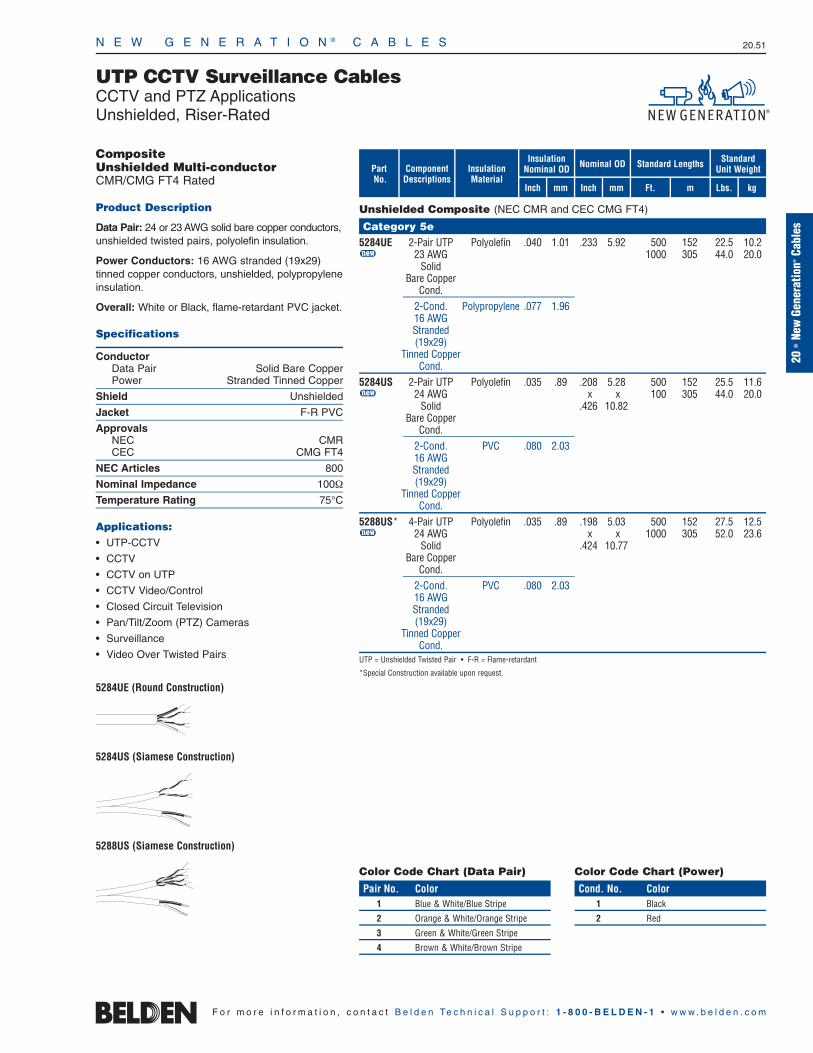
N E W G E N E R A T I O N ® C A B L E S 20.51
20•
New
Gene
ratio
n®Ca
bles
F o r m o r e i n f o r m a t i o n , c o n t a c t B e l d e n Te c h n i c a l S u p p o r t : 1 - 8 0 0 - B E L D E N - 1 • w w w . b e l d e n . c o m
UTP CCTV Surveillance CablesCCTV and PTZ ApplicationsUnshielded, Riser-Rated
Composite Unshielded Multi-conductorCMR/CMG FT4 Rated
Product Description
Data Pair: 24 or 23 AWG solid bare copper conductors,unshielded twisted pairs, polyolefin insulation.
Power Conductors: 16 AWG stranded (19x29)tinned copper conductors, unshielded, polypropyleneinsulation.
Overall: White or Black, flame-retardant PVC jacket.
Specifications
ConductorData Pair Solid Bare CopperPower Stranded Tinned Copper
Shield Unshielded
Jacket F-R PVC
ApprovalsNEC CMRCEC CMG FT4
NEC Articles 800
Nominal Impedance 100Ω
Temperature Rating 75°C
Applications: • UTP-CCTV
• CCTV
• CCTV on UTP
• CCTV Video/Control
• Closed Circuit Television
• Pan/Tilt/Zoom (PTZ) Cameras
• Surveillance
• Video Over Twisted Pairs
5284UE (Round Construction)
5284US (Siamese Construction)
5288US (Siamese Construction)
Unshielded Composite (NEC CMR and CEC CMG FT4)
Category 5e5284UE 2-Pair UTP Polyolefin .040 1.01 .233 5.92 500 152 22.5 10.2u 23 AWG 1000 305 44.0 20.0
SolidBare Copper
Cond.2-Cond. Polypropylene .077 1.9616 AWGStranded(19x29)
Tinned CopperCond.
5284US 2-Pair UTP Polyolefin .035 .89 .208 5.28 500 152 25.5 11.6u 24 AWG x x 100 305 44.0 20.0
Solid .426 10.82Bare Copper
Cond.2-Cond. PVC .080 2.0316 AWGStranded(19x29)
Tinned CopperCond.
5288US* 4-Pair UTP Polyolefin .035 .89 .198 5.03 500 152 27.5 12.5u 24 AWG x x 1000 305 52.0 23.6
Solid .424 10.77Bare Copper
Cond.2-Cond. PVC .080 2.0316 AWGStranded(19x29)
Tinned CopperCond.
UTP = Unshielded Twisted Pair • F-R = Flame-retardant
*Special Construction available upon request.
mFt.
Standard Lengths
mmInch kg
Standard Unit Weight
InsulationNominal OD Nominal OD
Inch mm Lbs.
PartNo.
ComponentDescriptions
InsulationMaterial
Color Code Chart (Data Pair)
Pair No. Color1 Blue & White/Blue Stripe
2 Orange & White/Orange Stripe
3 Green & White/Green Stripe
4 Brown & White/Brown Stripe
Color Code Chart (Power)
Cond. No. Color1 Black
2 Red

N E W G E N E R A T I O N ® C A B L E S 20.52
F o r m o r e i n f o r m a t i o n , c o n t a c t B e l d e n Te c h n i c a l S u p p o r t : 1 - 8 0 0 - B E L D E N - 1 • w w w . b e l d e n . c o m
UTP CCTV Surveillance CablesCCTV and PTZ ApplicationsUnshielded, Plenum-Rated
Unshielded Composite (NEC CMP and CEC CMP)
Category 5e6284UE 2-Pair UTP FEP .041 1.04 .220 5.59 500 152 19.5 8.8u 23 AWG 1000 305 38.0 17.2
SolidBare Copper
Cond.2-Cond. FEP .077 1.9616 AWGStranded(19x29)
Tinned CopperCond.
6284US 2-Pair UTP FEP .035 .89 .173 4.39 500 152 26.0 11.8u 24 AWG x x 1000 305 50.0 22.7
Solid .358 9.09Bare Copper
Cond.2-Cond. Flamarrest .077 1.9616 AWGStranded(19x29)
Tinned CopperCond.
6288US 4-Pair UTP FEP .042 1.07 .222 5.64 500 152 34.5 15.7u 23 AWG x x 1000 305 66.0 29.9
Solid .450 11.43Bare Copper
Cond.2-Cond. Flamarrest .077 1.9616 AWGStranded(19x29)
Tinned CopperCond.
FEP = Fluorinated Ethylene Propylene • UTP = Unshielded Twisted Pair
mFt.
Standard Lengths
mmInch kg
Standard Unit Weight
InsulationNominal OD Nominal OD
Inch mm Lbs.
PartNo.
ComponentDescriptions
InsulationMaterial
Composite Unshielded Multi-conductorCMP Rated
Product Description
Data Pair: 24 or 23 AWG solid bare copper conductors, unshielded twisted pairs, FEP insulation.
Power Conductors: 16 AWG stranded (19x29)tinned copper conductors, unshielded, FEP orFlamarrest® insulation.
Overall: White or Black, Flamarrest jacket.
Specifications
ConductorData Pair Solid Bare CopperPower Stranded Tinned Copper
Shield Unshielded
Jacket Flamarrest
ApprovalsNEC CMPCEC CMP
NEC Articles 800
Nominal Impedance 100Ω
Temperature Rating 75°C
Applications: • UTP-CCTV
• CCTV
• CCTV on UTP
• CCTV Video/Control
• Closed Circuit Television
• Pan/Tilt/Zoom (PTZ) Cameras
• Surveillance
• Video Over Twisted Pairs
6284UE (Round Construction)
6284US (Siamese Construction)
6288US (Siamese Construction)
Color Code Chart (Data Pair)
Pair No. Color1 Blue & White/Blue Stripe
2 Orange & White/Orange Stripe
3 Green & White/Green Stripe
4 Brown & White/Brown Stripe
Color Code Chart (Power)
Cond. No. Color1 Black
2 Red

N E W G E N E R A T I O N ® C A B L E S 20.53
20•
New
Gene
ratio
n®Ca
bles
F o r m o r e i n f o r m a t i o n , c o n t a c t B e l d e n Te c h n i c a l S u p p o r t : 1 - 8 0 0 - B E L D E N - 1 • w w w . b e l d e n . c o m
UTP CCTV Surveillance CablesCCTV Fixed and PTZ ApplicationsUnshielded, Non-Plenum
Unshielded Twisted PairsCM FT1 or CMR Rated
Product Description
Solid bare copper conductors, unshielded twistedpairs, polyolefin insulation, PVC jacket with rip cord.Sequential footage marking every two feet.
Specifications
Conductor Solid Bare Copper
Shield Unshielded
Jacket PVC
ApprovalsNEC CM or CMRCEC CM FT1 or CMR FT4
Nominal Impedance 100Ω
Temperature Rating 80°C
Applications: • 100BaseTX
• 100BaseVG ANYLAN
• 155ATM
• 622ATM
• AES/EBU
• Digital Video, RS-422
• Gigabit Ethernet
• NTSC/PAL Component or Composite Video
• Premise Horizontal Cable
• CCTV UTP
• PTZ
• Pan/Tilt/Zoom
Unshielded Twisted Pairs (NEC CM and CEC CM FT1)
Category 5e1583A 4-Pair UTP Polyolefin .008 0.20 .195 4.95 U-1000 U-305 21.0 9.5u 24 AWG 1000 305 21.0 9.5
Solid 1640 500 34.4 15.7Bare Copper 3000 915 63.0 28.6
Cond.1500A 4-Pair UTP Polyolefin .008 0.20 .200 5.08 A-1000 A-305 26.0 11.8u 24 AWG 1000 305 23.0 10.4
SolidBare Copper
Cond.
Unshielded Twisted Pairs (NEC CMR and CEC CMR FT4)
Category 5e1583R 4-Pair UTP Polyolefin .007 0.18 .197 5.00 U-1000 U-305 23.0 10.4u 24 AWG 1000 305 22.0 10.0
Solid 3000 915 63.0 28.6Bare Copper
Cond.1500R 4-Pair UTP Polyolefin .007 0.18 .194 5.00 A-1000 A-305 27.0 12.2u 24 AWG 1000 305 24.0 10.9
SolidBare Copper
Cond.Category 6
7881A 4-Pair UTP Polyolefin .010 0.18 .235 5.97 A-1000 A-305 33.0 15.0u 23 AWG 1000 305 30.0 13.6
SolidBare Copper
Cond.UTP = Unshielded Twisted Pair
Refer to www.belden.com for jacket colors and put-ups.
mFt.
Standard Lengths
mmInch kg
Standard Unit Weight
InsulationNominal OD Nominal OD
Inch mm Lbs.
PartNo.
ComponentDescriptions
InsulationMaterial
Color Code Chart
Pair No. Color Combinations1 White/Blue Stripe & Blue
2 White/Orange Stripe & Orange
3 White/Green Stripe & Green
4 White/Brown Stripe & Brown
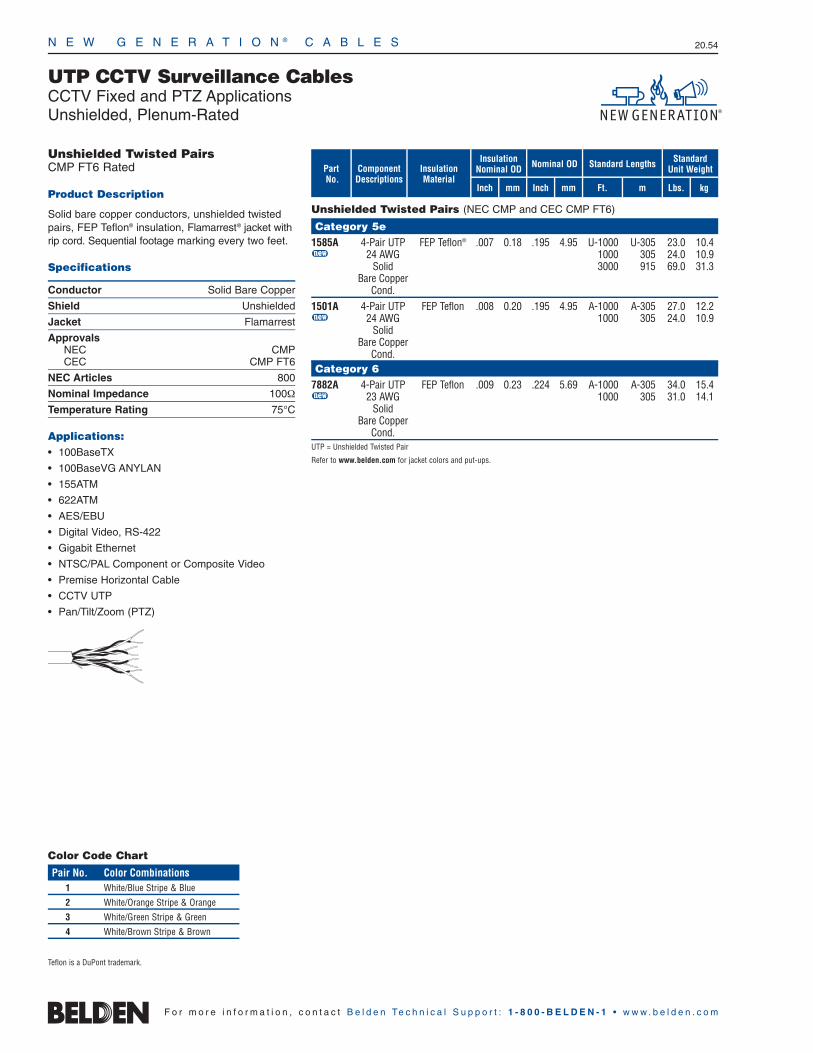
N E W G E N E R A T I O N ® C A B L E S 20.54
F o r m o r e i n f o r m a t i o n , c o n t a c t B e l d e n Te c h n i c a l S u p p o r t : 1 - 8 0 0 - B E L D E N - 1 • w w w . b e l d e n . c o m
UTP CCTV Surveillance CablesCCTV Fixed and PTZ ApplicationsUnshielded, Plenum-Rated
Unshielded Twisted PairsCMP FT6 Rated
Product Description
Solid bare copper conductors, unshielded twistedpairs, FEP Teflon® insulation, Flamarrest® jacket withrip cord. Sequential footage marking every two feet.
Specifications
Conductor Solid Bare Copper
Shield Unshielded
Jacket Flamarrest
ApprovalsNEC CMPCEC CMP FT6
NEC Articles 800
Nominal Impedance 100Ω
Temperature Rating 75°C
Applications: • 100BaseTX
• 100BaseVG ANYLAN
• 155ATM
• 622ATM
• AES/EBU
• Digital Video, RS-422
• Gigabit Ethernet
• NTSC/PAL Component or Composite Video
• Premise Horizontal Cable
• CCTV UTP
• Pan/Tilt/Zoom (PTZ)
Unshielded Twisted Pairs (NEC CMP and CEC CMP FT6)
Category 5e1585A 4-Pair UTP FEP Teflon® .007 0.18 .195 4.95 U-1000 U-305 23.0 10.4u 24 AWG 1000 305 24.0 10.9
Solid 3000 915 69.0 31.3Bare Copper
Cond.1501A 4-Pair UTP FEP Teflon .008 0.20 .195 4.95 A-1000 A-305 27.0 12.2u 24 AWG 1000 305 24.0 10.9
SolidBare Copper
Cond.Category 6
7882A 4-Pair UTP FEP Teflon .009 0.23 .224 5.69 A-1000 A-305 34.0 15.4u 23 AWG 1000 305 31.0 14.1
SolidBare Copper
Cond.UTP = Unshielded Twisted Pair
Refer to www.belden.com for jacket colors and put-ups.
mFt.
Standard Lengths
mmInch kg
Standard Unit Weight
InsulationNominal OD Nominal OD
Inch mm Lbs.
PartNo.
ComponentDescriptions
InsulationMaterial
Teflon is a DuPont trademark.
Color Code Chart
Pair No. Color Combinations1 White/Blue Stripe & Blue
2 White/Orange Stripe & Orange
3 White/Green Stripe & Green
4 White/Brown Stripe & Brown
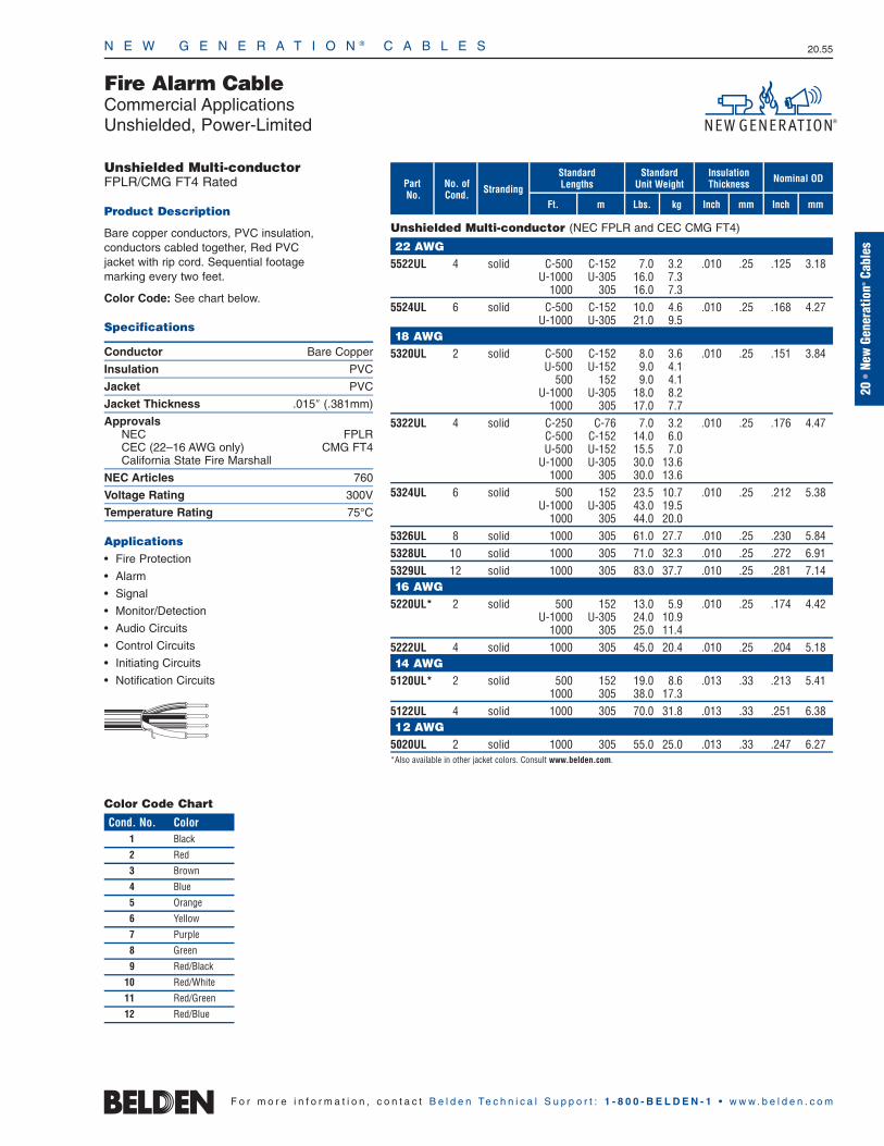
N E W G E N E R A T I O N ® C A B L E S 20.55
20•
New
Gene
ratio
n®Ca
bles
F o r m o r e i n f o r m a t i o n , c o n t a c t B e l d e n Te c h n i c a l S u p p o r t : 1 - 8 0 0 - B E L D E N - 1 • w w w . b e l d e n . c o m
Unshielded Multi-conductorFPLR/CMG FT4 Rated
Product Description
Bare copper conductors, PVC insulation, conductors cabled together, Red PVC jacket with rip cord. Sequential footage marking every two feet.
Color Code: See chart below.
Specifications
Conductor Bare Copper
Insulation PVC
Jacket PVC
Jacket Thickness .015″ (.381mm)
ApprovalsNEC FPLRCEC (22–16 AWG only) CMG FT4California State Fire Marshall
NEC Articles 760
Voltage Rating 300V
Temperature Rating 75°C
Applications• Fire Protection
• Alarm
• Signal
• Monitor/Detection
• Audio Circuits
• Control Circuits
• Initiating Circuits
• Notification Circuits
Fire Alarm CableCommercial ApplicationsUnshielded, Power-Limited
StrandingNo. of Cond.
mFt.
StandardLengths
mmInchkg
Standard Unit Weight
InsulationThickness Nominal OD
Inch mmLbs.
PartNo.
Unshielded Multi-conductor (NEC FPLR and CEC CMG FT4)
22 AWG5522UL 4 solid C-500 C-152 7.0 3.2 .010 .25 .125 3.18
U-1000 U-305 16.0 7.31000 305 16.0 7.3
5524UL 6 solid C-500 C-152 10.0 4.6 .010 .25 .168 4.27U-1000 U-305 21.0 9.5
18 AWG5320UL 2 solid C-500 C-152 8.0 3.6 .010 .25 .151 3.84
U-500 U-152 9.0 4.1500 152 9.0 4.1
U-1000 U-305 18.0 8.21000 305 17.0 7.7
5322UL 4 solid C-250 C-76 7.0 3.2 .010 .25 .176 4.47C-500 C-152 14.0 6.0U-500 U-152 15.5 7.0
U-1000 U-305 30.0 13.61000 305 30.0 13.6
5324UL 6 solid 500 152 23.5 10.7 .010 .25 .212 5.38U-1000 U-305 43.0 19.5
1000 305 44.0 20.05326UL 8 solid 1000 305 61.0 27.7 .010 .25 .230 5.845328UL 10 solid 1000 305 71.0 32.3 .010 .25 .272 6.915329UL 12 solid 1000 305 83.0 37.7 .010 .25 .281 7.1416 AWG
5220UL* 2 solid 500 152 13.0 5.9 .010 .25 .174 4.42U-1000 U-305 24.0 10.9
1000 305 25.0 11.45222UL 4 solid 1000 305 45.0 20.4 .010 .25 .204 5.1814 AWG
5120UL* 2 solid 500 152 19.0 8.6 .013 .33 .213 5.411000 305 38.0 17.3
5122UL 4 solid 1000 305 70.0 31.8 .013 .33 .251 6.3812 AWG
5020UL 2 solid 1000 305 55.0 25.0 .013 .33 .247 6.27*Also available in other jacket colors. Consult www.belden.com.
Color Code Chart
Cond. No. Color1 Black
2 Red
3 Brown
4 Blue
5 Orange
6 Yellow
7 Purple
8 Green
9 Red/Black
10 Red/White
11 Red/Green
12 Red/Blue

N E W G E N E R A T I O N ® C A B L E S 20.56
F o r m o r e i n f o r m a t i o n , c o n t a c t B e l d e n Te c h n i c a l S u p p o r t : 1 - 8 0 0 - B E L D E N - 1 • w w w . b e l d e n . c o m
Shielded Multi-conductorFPLR/CMG FT4 Rated
Product Description
Bare copper conductors, PVC insulation, conductors cabled together, Beldfoil® shield and drain wire, Red PVC jacket with rip cord.Sequential footage marking every two feet.
Color Code: See chart below.
Specifications
Conductor Bare Copper
Insulation PVC
Shield Beldfoil
Jacket PVC
Jacket Thickness .015″ (.381mm)
ApprovalsNEC FPLRCEC (22–16 AWG only) CMG FT4California State Fire Marshall
NEC Articles 760
Voltage Rating 300V
Temperature Rating 75°C
Applications• Fire Protection
• Alarm
• Signal
• Monitor/Detection
• Audio Circuits
• Control Circuits
• Initiating Circuits
• Notification Circuits
StrandingNo. of Cond.
mFt.
StandardLengths
mmInchkg
Standard Unit Weight
InsulationThickness Nominal OD
Inch mmLbs.
Fire Alarm CableCommercial ApplicationsShielded, Power-Limited
PartNo.
Shielded Multi-conductor (NEC FPLR and CEC CMG FT4)
22 AWG5522FL 4 solid C-500 C-152 9.0 4.1 .010 .25 .145 3.68
U-1000 U-305 19.0 8.61000 305 19.0 8.6
18 AWG5320FL* 2 solid C-500 C-152 10.5 4.8 .010 .25 .155 3.94
U-500 U-152 11.5 5.2500 152 11.5 5.2
U-1000 U-305 22.0 10.01000 305 22.0 10.0
5322FL 4 solid C-500 C-152 15.5 7.0 .010 .25 .170 4.32500 152 16.5 7.5
U-1000 U-305 32.0 14.51000 305 34.0 15.4
16 AWG5220FL* 2 solid 1000 305 29.0 13.2 .010 .25 .178 4.525222FL 4 solid 1000 305 50.0 22.7 .010 .25 .208 5.2814 AWG
5120FL* 2 solid 500 152 22.0 10.0 .013 .33 .217 5.511000 305 43.0 19.5
5122FL 4 solid 1000 305 79.0 35.9 .013 .33 .255 6.4812 AWG
5020FL 2 solid 1000 305 60.0 27.2 .013 .33 .251 6.38*Also available in other jacket colors. Consult www.belden.com.
Shorting Fold
Color Code Chart
Cond. No. Color1 Black
2 Red
3 Brown
4 Blue

N E W G E N E R A T I O N ® C A B L E S 20.57
20•
New
Gene
ratio
n®Ca
bles
F o r m o r e i n f o r m a t i o n , c o n t a c t B e l d e n Te c h n i c a l S u p p o r t : 1 - 8 0 0 - B E L D E N - 1 • w w w . b e l d e n . c o m
Unshielded Multi-conductorFPL Rated
Product Description
Bare copper conductors, foam high-density polyethylene insulation, cabled together, Red PVCjacket with rip cord. Sequential footage markingevery two feet.
Color Code: Black, Red.
Shielded Multi-conductorFPL Rated
Product Description
Bare copper conductors, foam high-density polyethylene insulation, cabled together, Beldfoil®
shield tape (foil side out), Red PVC jacket with ripcord. Sequential footage marking every two feet.
Color Code: See chart below.
Specifications
Conductor Bare Copper
Insulation FHDPE
Shield (where applicable) Beldfoil
Jacket PVC
Jacket Thickness .033″ (.838mm)
ApprovalsNEC FPLCalifornia State Fire Marshall
NEC Articles 760
Voltage Rating 300V
Temperature Rating 75°C
Nominal Capacitance*Unshielded† 13 pF/ft.Shielded†† 20–36 pF/ft.
*Capacitance between conductors.†60% lower capacitance than cables on page 20.55
††60% lower capacitance than cables on page 20.56
Applications• Addressable Fire Systems
• Data Circuits
• Audio Circuits
• Control Circuits
• Initiating Circuits
• Notification Circuits
StrandingNo. of Cond.
mFt.
StandardLengths
mmInchkg
Standard Unit Weight
InsulationThickness Nominal OD
Inch mmLbs.
Fire Alarm CableCommercial Applications, Addressable SystemsUnshielded or Shielded, Power-Limited, Mid-Capacitance
PartNo.
Unshielded Multi-conductor (NEC FPL)
18 AWG5320UJ 2 solid U-1000 U-305 22.0 10.0 .015 .38 .206 5.2316 AWG
5220UJ 2 solid 500 152 16.0 7.3 .015 .38 .230 5.841000 305 32.0 14.5
Shielded Multi-conductor (NEC FPL)
18 AWG5320FJ 2 solid U-1000 U-305 27.0 12.3 .015 .38 .211 5.36
1000 305 28.0 12.75322FJ 4 solid 1000 305 43.0 19.5 .015 .38 .240 6.1016 AWG
5220FJ 2 solid 500 152 18.0 8.2 .015 .38 .235 5.97U-1000 U-305 35.0 15.9
1000 305 37.0 16.85222FJ 4 solid 1000 305 59.0 26.8 .015 .38 .269 6.8314 AWG
5120FJ 2 solid 1000 305 49.0 22.3 .020 .51 .279 7.0912 AWG
5020FJ 2 solid 1000 305 69.0 31.3 .020 .51 .317 8.05
Unshielded
Shielded
Color Code Chart
Cond. No. Color1 Black
2 Red
3 Brown
4 Blue
Shorting Fold

N E W G E N E R A T I O N ® C A B L E S 20.58
F o r m o r e i n f o r m a t i o n , c o n t a c t B e l d e n Te c h n i c a l S u p p o r t : 1 - 8 0 0 - B E L D E N - 1 • w w w . b e l d e n . c o m
Unshielded Multi-conductorNPLF Rated150V Max. Per NEC Article 760Indoor (Non-conduit per NEC)
Product Description
Bare copper conductors, PVC/Nylon insulation,cabled together, Red PVC jacket with rip cord.Sequential footage marking every two feet.
Color Code: See chart below.
Shielded Multi-conductorNPLF Rated150V Max. Per NEC Article 760Indoor (Non-conduit per NEC)
Product Description
Bare copper conductors, PVC/Nylon insulation,cabled together, Beldfoil® shield tape (aluminumside out) plus drain wire, Red PVC jacket with rip cord. Sequential footage marking every two feet.
Color Code: See chart below.
Specifications
Conductor Bare Copper
Insulation PVC/Nylon
Insulation Thickness .021″ (.533mm)
Shield (where applicable) Beldfoil
Jacket PVC
ApprovalsNEC NPLF
NEC Articles 760
Voltage Rating 150V
Temperature Rating 75°C
Applications• Fire Alarm
• Audio Circuits
• Control Circuits
• Initiating Circuits
• Notification Circuits
StrandingNo. of Cond.
mFt.
StandardLengths
mmInchkg
Standard Unit Weight
Outer JacketThickness Nominal OD
Inch mmLbs.
Fire Alarm CableNPLF SystemsUnshielded or Shielded, Non-Power-Limited Signaling Cable
PartNo.
Unshielded Multi-conductor (NEC NPLF)
18 AWG5320UN 2 solid 500 152 14.0 6.4 .037 .94 .239 6.07
1000 305 31.0 14.15322UN 4 solid 500 152 28.0 12.7 .042 1.07 .283 7.19
1000 305 53.0 24.016 AWG
5220UN 2 solid 500 152 22.0 10.0 .037 .94 .262 6.651000 305 40.0 18.1
5222UN 4 solid 1000 305 71.0 32.3 .042 1.07 .311 7.9014 AWG
5120UN 2 solid 500 152 28.5 13.0 .042 1.07 .299 7.591000 305 53.0 24.1
Shielded Multi-conductor (NEC NPLF)
18 AWG5320FN 2 solid 500 152 15.5 7.0 .037 .94 .243 6.17
1000 305 35.0 15.95322FN 4 solid 500 152 31.0 14.1 .042 1.07 .287 7.29
1000 305 57.0 25.916 AWG
5220FN 2 solid 500 152 23.5 10.7 .037 .94 .266 6.761000 305 45.0 20.5
5222FN 4 solid 1000 305 76.0 34.5 .042 1.07 .315 8.0014 AWG
5120FN 2 solid 500 152 32.0 14.5 .042 1.07 .303 7.701000 305 61.0 27.7
5122FN 4 solid 500 152 50.5 23.0 .042 1.07 .348 8.841000 305 102.0 46.4
12 AWG5020FN 2 solid 500 152 43.0 19.5 .042 1.07 .337 8.56
1000 305 83.0 37.7
Unshielded
Shielded
Color Code Chart
Cond. No. Color
1 Black
2 Red
3 Brown
4 Blue
Shorting Fold

N E W G E N E R A T I O N ® C A B L E S 20.59
20•
New
Gene
ratio
n®Ca
bles
F o r m o r e i n f o r m a t i o n , c o n t a c t B e l d e n Te c h n i c a l S u p p o r t : 1 - 8 0 0 - B E L D E N - 1 • w w w . b e l d e n . c o m
Unshielded or Shielded Multi-conductorFPLP Rated
Product Description
Bare copper conductors, Flamarrest® insulation, cabled together, Red Flamarrest jacket with rip cord.Shielded version has overall Beldfoil® shield tape (foil side out) and drain wire. Sequential footagemarking every two feet.
Color Code: See chart below.
Specifications
Conductor Bare Copper
Insulation Flamarrest
Shield (where applicable) Beldfoil
Jacket Flamarrest
Jacket Thickness .015″ (.381mm)
ApprovalsNEC FPLPCalifornia State Fire Marshall
NEC Articles 760
Voltage Rating 300V
Temperature Rating 75°C
Applications• Fire Protection
• Alarm
• Signal
• Monitor/Detection
• Audio Circuits
• Control Circuits
• Initiating Circuits
• Notification Circuits
Unshielded
Shielded
StrandingNo. of Cond.
mFt.
StandardLengths
mmInchkg
Standard Unit Weight
InsulationThickness Nominal OD
Inch mmLbs.
Fire Alarm CableCommercial ApplicationsUnshielded or Shielded, Plenum-Rated, Power-Limited
PartNo.
Unshielded Multi-conductor (NEC FPLP)
22 AWG6522UL 4 solid U-1000 U-305 17.0 7.7 .009 .23 .136 3.45
1000 305 16.0 7.36524UL 6 solid C-500 C-152 10.5 4.8 .009 .23 .162 4.12
U-1000 U-305 22.0 10.01000 305 22.0 10.0
18 AWG6320UL* 2 solid C-500 C-152 8.0 3.6 .010 .25 .151 3.84
U-500 U-152 9.0 4.1U-1000 U-305 18.0 8.2
1000 305 17.0 7.76321UL 3 solid 1000 305 28.0 12.7 .010 .25 .160 4.066322UL 4 solid C-250 C-76 7.2 3.3 .010 .25 .183 4.64
C-500 C-152 14.5 6.61000 305 31.0 14.1
6324UL 6 solid U-1000 U-305 44.0 20.0 .010 .25 .211 5.361000 305 46.0 20.9
6326UL 8 solid 1000 305 63.0 28.6 .010 .25 .230 5.846328UL 10 solid 1000 305 73.0 33.1 .010 .25 .272 6.9116 AWG
6220UL* 2 solid C-500 C-152 12.0 5.4 .010 .25 .174 4.42500 152 12.5 5.7
U-1000 U-305 25.0 11.41000 305 26.0 11.8
6222UL 4 solid 500 152 24.5 11.1 .010 .25 .204 5.181000 305 47.0 21.3
14 AWG6120UL* 2 solid 500 152 19.0 8.6 .011 .28 .205 5.21
1000 305 38.0 17.36122UL 4 solid 500 152 35.5 16.1 .011 .28 .241 6.12
1000 305 70.0 31.812 AWG
6020UL 2 solid 1000 305 59.0 26.8 .011 .28 .239 6.07
Shielded Multi-conductor (NEC FPLP)
18 AWG6320FL* 2 solid C-500 C-152 10.5 4.8 .010 .25 .158 4.01
U-1000 U-305 22.0 10.01000 305 22.0 10.0
6322FL 4 solid 1000 305 36.0 16.4 .010 .25 .183 4.6516 AWG
6220FL* 2 solid C-500 C-152 14.5 6.6 .010 .25 .181 4.601000 305 31.0 14.1
6222FL 4 solid 1000 305 58.0 26.3 .010 .25 .211 5.3614 AWG
6120FL* 2 solid 500 152 23.5 10.7 .011 .28 .209 5.311000 305 45.0 20.4
6122FL 4 solid 500 152 42.0 19.1 .011 .28 .245 6.221000 305 77.0 35.0
12 AWG6020FL 2 solid 500 152 30.5 13.9 .011 .28 .243 6.17
1000 305 61.0 27.7*Also available in other jacket colors. Consult www.belden.com.
Color Code Chart
Cond. No. Color
1 Black
2 Red
3 Brown
4 Blue
5 Orange
Cond. No. Color
6 Yellow
7 Purple
8 Green
9 Red/Black
10 Red/White
Shorting Fold

N E W G E N E R A T I O N ® C A B L E S 20.60
Unshielded Multi-conductorFPLP Rated
Product Description
Bare copper conductors, FEP insulation, cabledtogether, Red Flamarrest® jacket with rip cord.Sequential footage marking every two feet.
Color Code: Black, Red.
Shielded Multi-conductorFPLP Rated
Product Description
Bare copper conductors, FEP insulation, cabledtogether, Beldfoil® shield tape (aluminum side out)with tinned copper drain wire, Red Flamarrest jacket with rip cord. Sequential footage marking every two feet.
Color Code: Black, Red.
Specifications
Conductor Bare Copper
Insulation FEP
Shield (where applicable) Beldfoil
Jacket Flamarrest
Jacket Thickness .015″ (.381mm)
ApprovalsNEC FPLPCalifornia State Fire Marshall
NEC Articles 760
Voltage Rating 300V
Temperature Rating 75°C
Nominal Capacitance*Unshielded† 26 pF/ft.Shielded†† 26–31 pF/ft.
*Capacitance between conductors.†20% lower capacitance than cables on page 13.39
††60% lower capacitance than cables on page 13.39
Applications• Addressable Fire Systems
• Data Circuits
• Monitor/Detection
• Control Circuits
• Initiating Circuits
• Notification Circuits
StrandingNo. of Cond.
mFt.
StandardLengths
mmInchkg
Standard Unit Weight
InsulationThickness Nominal OD
Inch mmLbs.
Fire Alarm CableCommercial Applications, Addressable SystemsUnshielded and Shielded, Plenum-Rated, Power-Limited, Mid-Capacitance
PartNo.
Unshielded Multi-conductor (NEC FPLP)
18 AWG6320UJ 2 solid 1000 305 16.0 7.3 .007 .18 .138 3.5116 AWG
6220UJ 2 solid 1000 305 24.0 10.9 .007 .18 .162 4.1114 AWG
6120UJ 2 solid 1000 305 32.0 14.5 .007 .18 .186 4.72
Shielded Multi-conductor (NEC FPLP)
18 AWG6320FK 2 solid 500 152 14.0 6.4 .018 .46 .185 4.70
U-1000 U-305 28.0 12.71000 305 27.0 12.2
16 AWG6220FK 2 solid 1000 305 37.0 16.8 .018 .46 .210 5.33
Unshielded
Shielded
Shorting Fold
F o r m o r e i n f o r m a t i o n , c o n t a c t B e l d e n Te c h n i c a l S u p p o r t : 1 - 8 0 0 - B E L D E N - 1 • w w w . b e l d e n . c o m

N E W G E N E R A T I O N ® C A B L E S 20.61
StrandingNo. of Cond.
mFt.
StandardLengths
mmInchkg
Standard Unit Weight
Outer JacketThickness Nominal OD
Inch mmLbs.
Circuit Integrity in Conduit (CIC) Safe-T-Line® CableCommercial Applications, Addressable SystemsUnshielded, Riser-Rated
PartNo.
Unshielded Multi-conductor (NEC FPLR-CIC)
16 AWG5200UZ 2 7 1000 305 68.0 30.9 .056 1.42 .37 9.40u5220UZ 2 solid 1000 305 64.0 29.0 .056 1.42 .35 8.89u14 AWG
5100UZ 2 7 1000 305 87.0 39.5 .056 1.42 .40 10.16u5120UZ 2 solid 1000 305 79.0 35.8 ..056 1.42 .38 9.65u12 AWG
5000UZ 2 7 1000 305 108.0 50.0 .056 1.42 .37 9.40u5020UZ 2 solid 1000 305 101.0 45.8 .056 1.42 .42 10.67uFRPE = Flame-retardant Polyethylene
Unshielded Multi-conductorFPLR-CIC Rated
Product Description
Bare copper conductors, ceramifiable silicone rubberinsulation, Red FRPE (Low-Smoke, Non-Halogen)jacket. Sequential footage marking every two feet.
Color Code: Black, Red.
Specifications
Conductor Bare Copper
Insulation Silicone Rubber
Shield Unshielded
Jacket FRPE
Jacket Thickness .035″ (.889mm)
ApprovalsNEC FPLR-CIC
NEC Articles 760
Voltage Rating 300V
Temperature Rating 105°CNote: 2-conductor versions are color-coded black and red. 4 or more conductor versions are all black and numbered.
Applications• Circuit Integrity
• Fire Alarm Circuit Integrity
• Survivability
• Survivability from Attack by Fire
Stranded
Solid
20•
New
Gene
ratio
n®Ca
bles
F o r m o r e i n f o r m a t i o n , c o n t a c t B e l d e n Te c h n i c a l S u p p o r t : 1 - 8 0 0 - B E L D E N - 1 • w w w . b e l d e n . c o m

StrandingNo. of Cond.
mFt.
StandardLengths
mmInchkg
Standard Unit Weight
Outer JacketThickness Nominal OD
Inch mmLbs.
N E W G E N E R A T I O N ® C A B L E S 20.62
Circuit Integrity in Conduit (CIC) Safe-T-Line® CableCommercial Applications, Addressable SystemsShielded, Riser-Rated
PartNo.
Shielded Multi-conductor (NEC FPLR-CIC)
16 AWG5200FZ 2 7 1000 305 75.0 34.0 .056 1.42 .37 9.40u5220FZ 2 solid 1000 305 71.0 32.2 .056 1.42 .36 9.14u5222FZ 4 solid 1000 305 108.0 50.0 .056 1.42 .41 10.41u14 AWG
5100FZ 2 7 1000 305 97.0 44.0 .056 1.42 .41 10.41u5120FZ 2 solid 1000 305 90.0 40.8 ..056 1.42 .38 9.65u12 AWG
5000FZ 2 7 1000 305 122.0 55.3 .056 1.42 .44 11.18u5020FZ 2 solid 1000 305 117.0 53.1 .056 1.42 .42 10.67u5022FZ 4 solid 1000 305 187.0 84.8 .056 1.42 .48 12.19uFRPE = Flame-retardant Polyethylene
Shielded Multi-conductorFPLR-CIC Rated
Product Description
Bare copper conductors, ceramifiable silicone rubberinsulation, overall Beldfoil® Shield (100% coverage),tinned copper drain wire, Red FRPE (Low-Smoke,Non-Halogen) jacket, Sequential footage markingevery two feet.
Color Code: Black, Red. (see note)
Specifications
Conductor Bare Copper
Insulation Silicone Rubber
Shield Beldfoil
Jacket FRPE
Jacket Thickness .035″ (.889mm)
ApprovalsNEC FPLR-CIC
NEC Articles 760
Voltage Rating 300V
Temperature Rating 105°CNote: 2-conductor versions are color-coded black and red. 4 or more conductor versions are all black and numbered.
Applications• Circuit Integrity
• Fire Alarm Circuit Integrity
• Survivability
• Survivability from Attack by Fire
Stranded
Solid
F o r m o r e i n f o r m a t i o n , c o n t a c t B e l d e n Te c h n i c a l S u p p o r t : 1 - 8 0 0 - B E L D E N - 1 • w w w . b e l d e n . c o m
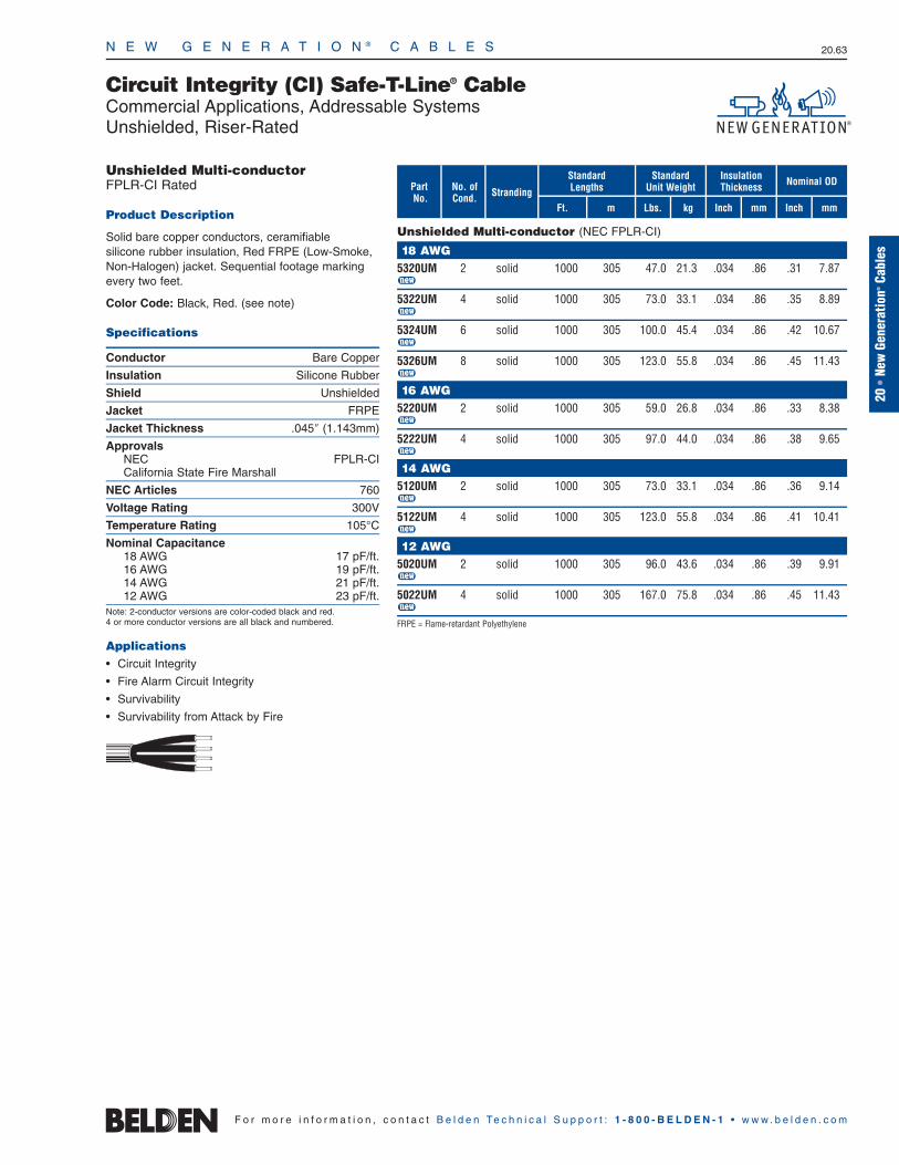
N E W G E N E R A T I O N ® C A B L E S 20.63
20•
New
Gene
ratio
n®Ca
bles
StrandingNo. of Cond.
mFt.
StandardLengths
mmInchkg
Standard Unit Weight
InsulationThickness Nominal OD
Inch mmLbs.
Circuit Integrity (CI) Safe-T-Line® CableCommercial Applications, Addressable SystemsUnshielded, Riser-Rated
PartNo.
Unshielded Multi-conductor (NEC FPLR-CI)
18 AWG5320UM 2 solid 1000 305 47.0 21.3 .034 .86 .31 7.87u5322UM 4 solid 1000 305 73.0 33.1 .034 .86 .35 8.89u5324UM 6 solid 1000 305 100.0 45.4 .034 .86 .42 10.67u5326UM 8 solid 1000 305 123.0 55.8 .034 .86 .45 11.43u16 AWG
5220UM 2 solid 1000 305 59.0 26.8 .034 .86 .33 8.38u5222UM 4 solid 1000 305 97.0 44.0 .034 .86 .38 9.65u14 AWG
5120UM 2 solid 1000 305 73.0 33.1 .034 .86 .36 9.14u5122UM 4 solid 1000 305 123.0 55.8 .034 .86 .41 10.41u12 AWG
5020UM 2 solid 1000 305 96.0 43.6 .034 .86 .39 9.91u5022UM 4 solid 1000 305 167.0 75.8 .034 .86 .45 11.43uFRPE = Flame-retardant Polyethylene
Unshielded Multi-conductorFPLR-CI Rated
Product Description
Solid bare copper conductors, ceramifiable silicone rubber insulation, Red FRPE (Low-Smoke, Non-Halogen) jacket. Sequential footage markingevery two feet.
Color Code: Black, Red. (see note)
Specifications
Conductor Bare Copper
Insulation Silicone Rubber
Shield Unshielded
Jacket FRPE
Jacket Thickness .045″ (1.143mm)
ApprovalsNEC FPLR-CICalifornia State Fire Marshall
NEC Articles 760
Voltage Rating 300V
Temperature Rating 105°C
Nominal Capacitance18 AWG 17 pF/ft.16 AWG 19 pF/ft.14 AWG 21 pF/ft.12 AWG 23 pF/ft.
Note: 2-conductor versions are color-coded black and red. 4 or more conductor versions are all black and numbered.
Applications• Circuit Integrity
• Fire Alarm Circuit Integrity
• Survivability
• Survivability from Attack by Fire
F o r m o r e i n f o r m a t i o n , c o n t a c t B e l d e n Te c h n i c a l S u p p o r t : 1 - 8 0 0 - B E L D E N - 1 • w w w . b e l d e n . c o m

N E W G E N E R A T I O N ® C A B L E S 20.64
F o r m o r e i n f o r m a t i o n , c o n t a c t B e l d e n Te c h n i c a l S u p p o r t : 1 - 8 0 0 - B E L D E N - 1 • w w w . b e l d e n . c o m
StrandingNo. of Cond.
mFt.
StandardLengths
mmInchkg
Standard Unit Weight
InsulationThickness Nominal OD
Inch mmLbs.
Circuit Integrity (CI) Safe-T-Line® CableCommercial Applications, Addressable SystemsShielded, Riser-Rated
PartNo.
Shielded Multi-conductor (NEC FPLR-CI)
18 AWG5320FM 2 solid 1000 305 50.0 22.7 .034 .86 .31 7.87u5322FM 4 solid 1000 305 78.0 35.4 .034 .86 .36 9.14u5324FM 6 solid 1000 305 106.0 48.1 .034 .86 .42 10.67u5326FM 8 solid 1000 305 129.0 58.5 .034 .86 .46 11.61u5300FM 2 (7x26) 1000 305 57.0 25.9 .034 .86 .32 8.13u5302FM 4 (7x26) 1000 305 103.0 46.7 .034 .86 .37 9.40u5304FM 6 (7x26) 1000 305 122.0 55.3 .034 .86 .44 11.18u5306FM 8 (7x26) 1000 305 148.0 67.1 .034 .86 .47 11.94u16 AWG
5220FM 2 solid 1000 305 66.0 29.9 .034 .86 .33 8.38u5222FM 4 solid 1000 305 103.0 46.7 .034 .86 .38 9.65u5200FM 2 (7x24) 1000 305 71.0 32.2 .034 .86 .35 8.89u5202FM 4 (7x24) 1000 305 112.0 50.8 .034 .86 .40 10.16u14 AWG
5120FM 2 solid 1000 305 84.0 38.1 .034 .86 .36 9.14u5122FM 4 solid 1000 305 133.0 60.3 .034 .86 .41 10.41u5100FM 2 (7x22) 1000 305 93.0 42.2 .034 .86 .38 9.65u5102FM 4 (7x22) 1000 305 149.0 67.6 .034 .86 .44 11.18u12 AWG
5020FM 2 solid 1000 305 112.0 50.8 .034 .86 .39 9.91u5022FM 4 solid 1000 305 183.0 83.0 .034 .86 .46 11.68u5000FM 2 (7x20) 1000 305 117.0 53.1 .034 .86 .42 10.67u5002FM 4 (7x20) 1000 305 189.0 85.7 .034 .86 .48 12.19uFRPE = Flame-retardant Polyethylene
Shielded Multi-conductorFPLR-CI Rated
Product Description
Bare copper conductors, ceramifiable silicone rubberinsulation, Beldfoil® shield (100% coverage), RedFRPE (Low-Smoke, Non-Halogen) jacket, drain wire.Sequential footage marking every two feet.
Color Code: Black, Red.
Specifications
Conductor Bare Copper
Insulation Silicone Rubber
Shield Beldfoil
Jacket FRPE
Jacket Thickness .045″ (1.143mm)
ApprovalsNEC FPLR-CICalifornia State Fire Marshall
NEC Articles 760
Voltage Rating 300V
Temperature Rating 105°C
Nominal Capacitance18 AWG 27 pF/ft.16 AWG 31 pF/ft.14 AWG 33 pF/ft.12 AWG 37 pF/ft. *
40 pF/ft. *** 5020FM and 5022FM
** 5000FM and 5002FM
Note: 2-conductor versions are color-coded black and red. 4 or more conductor versions are all black and numbered.
Applications• Circuit Integrity
• Fire Alarm Circuit Integrity
• Survivability
• Survivability from Attack by Fire
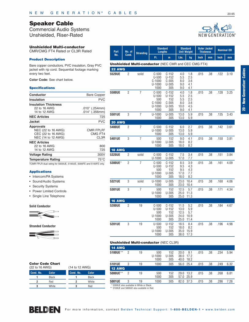
N E W G E N E R A T I O N ® C A B L E S 20.65
20•
New
Gene
ratio
n®Ca
bles
F o r m o r e i n f o r m a t i o n , c o n t a c t B e l d e n Te c h n i c a l S u p p o r t : 1 - 8 0 0 - B E L D E N - 1 • w w w . b e l d e n . c o m
Unshielded Multi-conductorCMR/CMG FT4 Rated or CL3R Rated
Product Description
Bare copper conductors, PVC insulation, Gray PVCjacket with rip cord. Sequential footage markingevery two feet.
Color Code: See chart below.
Specifications
Conductor Bare Copper
Insulation PVC
Insulation Thickness22 to 16 AWG .010″ (.254mm)14 to 12 AWG .014″ (.356mm)
NEC Articles 725
Jacket PVC
ApprovalsNEC (22 to 16 AWG) CMR FPLR†
CEC (22 to 16 AWG) CMG FT4NEC (14 to 12 AWG) CL3R
NEC Articles22 to 16 AWG 80014 to 12 AWG 725
Voltage Rating 300V
Temperature Rating 75°C†CMR FPLR dual rating for 5000UE, 5100UE, 5000FE and 5100FE only.
Applications• Intercom/PA Systems
• Sound/Audio Systems
• Security Systems
• Power Limited Controls
• Single Line Telephone
Solid Conductor
Stranded Conductor
StrandingNo. of Cond.
mFt.
StandardLengths
mmInchkg
Standard Unit Weight
Outer JacketThickness Nominal OD
Inch mmLbs.
Speaker CableCommercial Audio SystemsUnshielded, Riser-Rated
PartNo.
Unshielded Multi-conductor (NEC CMR and CEC CMG FT4)
22 AWG5520UE 2 solid C-500 C-152 4.0 1.8 .015 .38 .122 3.10
U-500 U-152 5.5 2.5C-1000 C-305 8.0 3.6U-1000 U-305 9.0 4.1
1000 305 9.0 4.15500UE 2 7 C-500 C-152 4.0 1.8 .015 .38 .128 3.25
U-500 U-152 5.5 2.5500 152 5.5 2.5
C-1000 C-305 8.0 3.6U-1000 U-305 10.0 4.5
1000 305 9.0 4.15501UE 3 7 U-1000 U-305 13.0 5.9 .015 .38 .135 3.43
1000 305 13.0 5.920 AWG
5400UE 2 7 C-500 C-152 6.0 2.7 .015 .38 .142 3.61U-1000 U-305 13.0 5.9
1000 305 13.0 5.95401UE 3 7 500 152 9.0 4.1 .015 .38 .150 3.81
U-1000 U-305 18.0 8.21000 305 18.0 8.2
18 AWG5320UE 2 solid C-500 C-152 7.5 3.4 .015 .38 .151 3.84
U-1000 U-305 17.0 7.75300UE* 2 7 C-500 C-152 8.5 3.9 .015 .38 .161 4.09
U-500 U-152 9.5 4.3500 152 9.5 4.3
U-1000 U-305 17.0 7.71000 305 18.0 8.2
5321UE 3 solid U-1000 U-305 23.0 10.4 .015 .38 .160 4.061000 305 23.0 10.4
5301UE 3 7 500 152 12.5 5.7 .015 .38 .171 4.34U-1000 U-305 25.0 11.3
1000 305 25.0 11.316 AWG
5200UE 2 19 C-500 C-152 11.5 5.2 .015 .38 .184 4.67U-500 U-152 13.0 5.9
500 152 12.5 5.7U-1000 U-305 24.0 10.9
1000 305 25.0 11.45201UE 3 19 U-500 U-152 18.5 8.4 .015 .38 .196 4.98
500 152 18.0 8.2U-1000 U-305 35.0 15.9
1000 305 38.0 17.3
Unshielded Multi-conductor (NEC CL3R)
14 AWG5100UE** 2 19 500 152 20.0 9.1 .015 .38 .234 5.94
U-1000 U-305 38.0 17.21000 305 40.0 18.2
5101UE 3 19 1000 305 56.0 25.4 .015 .38 .249 6.3212 AWG
5000UE** 2 19 500 152 29.0 13.2 .015 .38 .268 6.811000 305 57.0 25.9
5001UE 3 19 1000 305 82.0 37.3 .015 .38 .286 7.26* 5300UE also available in White or Black.
** 5100UE and 5000UE also available in Red.
Color Code Chart(22 to 16 AWG)
Cond. No. Color
1 Black
2 Red
3 White
(14 to 12 AWG)
Cond. No. Color
1 Black
2 White
3 Red
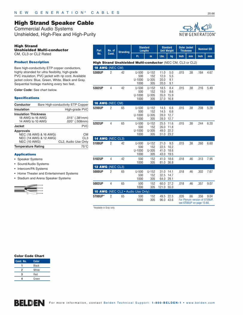
N E W G E N E R A T I O N ® C A B L E S 20.66
F o r m o r e i n f o r m a t i o n , c o n t a c t B e l d e n Te c h n i c a l S u p p o r t : 1 - 8 0 0 - B E L D E N - 1 • w w w . b e l d e n . c o m
StrandingNo. of Cond.
mFt.
StandardLengths
mmInchkg
Standard Unit Weight
Outer JacketThickness Nominal OD
Inch mmLbs.
High Strand Speaker CableCommercial Audio SystemsUnshielded, High-Flex and High-Purity
PartNo.
High Strand Unshielded Multi-conductor (NEC CM, CL3 or CL2)
18 AWG (NEC CM)
5300UP 2 42 U-500 U-152 11.0 5.0 .015 .38 .184 4.67500 152 12.0 5.5
U-1000 U-305 20.0 9.11000 305 20.0 9.1
5302UP 4 42 U-500 U-152 18.5 8.4 .015 .38 .216 5.49500 152 19.0 8.6
U-1000 U-305 35.0 15.91000 305 37.0 16.8
16 AWG (NEC CM)
5200UP 2 65 U-500 U-152 14.5 6.6 .015 .38 .208 5.28500 152 14.5 6.6
U-1000 U-305 28.0 12.71000 305 28.0 12.7
5202UP 4 65 U-500 U-152 25.5 11.6 .015 .38 .244 6.20500 152 26.0 11.8
U-1000 U-305 49.0 22.21000 305 51.0 23.2
14 AWG (NEC CL3)
5100UP 2 42 U-500 U-152 21.0 9.5 .015 .38 .260 6.60500 152 22.5 10.2
U-1000 U-305 41.0 18.61000 305 43.0 19.5
5102UP 4 42 500 152 41.0 18.6 .018 .46 .313 7.951000 305 81.0 36.8
12 AWG (NEC CL3)
5000UP 2 65 U-500 U-152 31.0 14.1 .018 .46 .302 7.67500 152 32.5 14.7
1000 305 64.0 29.15002UP 4 65 500 152 60.0 27.2 .018 .46 .357 9.07
1000 305 121.0 55.010 AWG (NEC CL2 • Audio Use Only)
5T00UP* 2 65 500 152 49.5 22.5 .026 .66 .356 9.041000 305 96.0 43.6
*Available in Gray only.
High Strand Unshielded Multi-conductorCM, CL3 or CL2 Rated
Product Description
Bare high-conductivity ETP copper conductors,highly stranded for ultra flexibility, high-grade PVC insulation, PVC jacket with rip cord. Availablejacket colors: Blue, Green, White, Black and Gray.Sequential footage marking every two feet.
Color Code: See chart below.
Specifications
Conductor Bare High-conductivity ETP Copper
Insulation High-grade PVC
Insulation Thickness18 AWG to 16 AWG .015″ (.381mm) 14 AWG to 10 AWG .020″ (.508mm)
Jacket PVC
ApprovalsNEC (18 AWG & 16 AWG) CMNEC (14 AWG & 12 AWG) CL3NEC (10 AWG) CL2, Audio Use Only
Temperature Rating 75°C
Applications• Speaker Systems
• Sound/Audio Systems
• Intercom/PA Systems
• Home Theater and Entertainment Systems
• Stadium and Arena Speaker Systems
For Plenum version of 5T00UP, see 6T00UP on page 13.60.
Color Code Chart
Cond. No. Color
1 Black
2 White
3 Red
4 Green

N E W G E N E R A T I O N ® C A B L E S 20.67
20•
New
Gene
ratio
n®Ca
bles
F o r m o r e i n f o r m a t i o n , c o n t a c t B e l d e n Te c h n i c a l S u p p o r t : 1 - 8 0 0 - B E L D E N - 1 • w w w . b e l d e n . c o m
Shielded Multi-conductorCMR/CMG FT4 Rated or CL3R Rated
Product Description
Bare copper conductors, PVC insulation, conductorscabled, Beldfoil® shield tape (foil side out) with drainwire, Gray PVC jacket with rip cord. Sequentialfootage marking every two feet.
Color Code: See chart below.
Specifications
Conductor Bare Copper
Insulation PVC
Insulation Thickness24 to 16 AWG .010″ (.254mm)14 to 12 AWG .014″ (.356mm)
Shield Beldfoil
Jacket PVC
ApprovalsNEC (24 to 16 AWG) CMR FPLR†
CEC (24 to 16 AWG) CMG FT4NEC (14 to 12 AWG) CL3R
NEC Articles24 to 16 AWG 80014 to 12 AWG 725
Voltage Rating 300V
Temperature Rating 75°C†CMR FPLR dual rating for 5000UE, 5100UE, 5000FE and 5100FE only.
Applications• Intercom/PA Systems
• Sound/Audio Systems
• Fire Alarm Systems (Red Only)
Solid Conductor
Stranded Conductor
StrandingNo. of Cond.
mFt.
StandardLengths
mmInchkg
Standard Unit Weight
Outer JacketThickness Nominal OD
Inch mmLbs.
Audio CableCommercial Audio SystemsShielded, Riser-Rated or CL3R Rated
PartNo.
Shielded Multi-conductor (NEC CMR and CEC CMG FT4)
24 AWG5600FE 2 7 U-1000 U-305 11.0 5.0 .015 .38 .120 3.05
1000 305 10.0 4.522 AWG
5520FE 2 solid C-500 C-152 6.5 3.0 .015 .38 .125 3.18C-1000 C-305 13.0 5.9U-1000 U-305 14.0 6.4
1000 305 14.0 6.45500FE 2 7 C-500 C-152 5.5 2.5 .015 .38 .130 3.30
U-500 U-152 6.5 3.0500 152 6.5 3.0
U-1000 U-305 12.0 5.51000 305 12.0 5.5
5521FE 3 solid U-1000 U-305 12.0 5.4 .015 .38 .132 3.351000 305 12.0 5.4
5501FE 3 7 C-500 C-152 7.0 3.2 .015 .38 .138 3.51U-500 U-152 8.0 3.6
500 152 7.5 3.4U-1000 U-305 15.0 6.8
1000 305 15.0 6.820 AWG
5400FE 2 7 U-500 U-152 9.0 4.1 .015 .38 .145 3.68500 152 8.5 3.9
U-1000 U-305 17.0 7.71000 305 17.0 7.7
5421FE 3 solid U-1000 U-305 20.0 9.1 .015 .38 .146 3.715401FE 3 7 U-500 U-152 11.0 5.0 .015 .38 .153 3.89
500 152 10.5 4.8U-1000 U-305 21.0 9.5
1000 305 21.0 9.518 AWG
5320FE 2 solid C-500 C-152 10.0 4.5 .015 .38 .155 3.94U-1000 U-305 21.0 9.5
1000 305 21.0 9.55300FE 2 7 C-500 C-152 11.0 5.0 .015 .38 .165 4.19
U-500 U-152 12.0 5.4500 152 12.0 5.4
U-1000 U-305 23.0 10.41000 305 23.0 10.4
5301FE 3 7 U-500 U-152 15.5 7.0 .015 .38 .175 4.45500 152 15.0 6.8
U-1000 U-305 30.0 13.61000 305 30.0 13.6
16 AWG5200FE* 2 19 U-500 U-152 16.5 7.5 .015 .38 .188 4.78
500 152 16.5 7.5U-1000 U-305 31.0 14.1
1000 305 32.0 14.55201FE 3 19 500 152 21.5 9.8 .015 .38 .200 5.08
U-1000 U-305 42.0 19.11000 305 42.0 19.1
Shielded Multi-conductor (NEC CL3R)
14 AWG5100FE** 2 19 500 152 28.5 13.0 .015 .38 .238 6.05
U-1000 U-305 49.0 22.31000 305 51.0 23.2
5101FE 3 19 1000 305 66.0 30.0 .015 .38 .253 6.4312 AWG
5000FE** 2 19 500 152 36.5 16.6 .015 .38 .272 6.911000 305 67.0 30.4
* 5200FE also available in White.** 5100FE and 5000FE also available in Red (rating FPLR).
Shorting Fold
Shorting Fold
Color Code Chart(24 to 16 AWG)
Cond. No. Color
1 Black
2 Red
3 White
(14 to 12 AWG)
Cond. No. Color
1 Black
2 White
3 Red

N E W G E N E R A T I O N ® C A B L E S 20.68
F o r m o r e i n f o r m a t i o n , c o n t a c t B e l d e n Te c h n i c a l S u p p o r t : 1 - 8 0 0 - B E L D E N - 1 • w w w . b e l d e n . c o m
Unshielded Multi-conductorCMP FT6 Rated or CL2P Rated
Product Description
Bare copper conductors, Flamarrest® insulation, conductors cabled, Natural Flamarrest jacket with rip cord. Sequential footage marking every two feet.
Color Code: See chart below.
Specifications
Conductor Bare Copper
Insulation Flamarrest
Insulation Thickness22 to 16 AWG .009″ (.229mm) 14 to 10 AWG .011″ (.279mm)
Jacket Flamarrest
ApprovalsNEC (22 to 16 AWG) CMPCEC (22 to 16 AWG) CMP FT6NEC (14 to 10 AWG) CL2P
NEC Articles22 to 16 AWG 80014 to 10 AWG 725
Voltage Rating22 to 16 AWG 300V14 to 10 AWG 150V
Temperature Rating 75°C
Applications• Intercom/PA Systems
• Sound/Audio Systems
Solid Conductor
Stranded Conductor
StrandingNo. of Cond.
mFt.
StandardLengths
mmInchkg
Standard Unit Weight
Outer JacketThickness Nominal OD
Inch mmLbs.
Audio CableCommercial Audio SystemsUnshielded, Plenum-Rated
PartNo.
Unshielded Multi-conductor (NEC CMP and CEC CMP FT6)
22 AWG6520UE 2 solid U-1000 U-305 10.0 4.5 .015 .38 .118 3.00
1000 305 9.0 4.16500UE 2 7 C-500 C-152 4.5 2.0 .015 .38 .124 3.15
C-1000 C-305 9.0 4.1U-1000 U-305 10.0 4.5
1000 305 10.0 4.56521UE 3 solid 1000 305 13.0 5.9 .015 .38 .125 3.186501UE 3 7 U-1000 U-305 14.0 6.4 .015 .38 .131 3.33
1000 305 13.0 5.920 AWG
6400UE 2 7 C-500 C-152 6.0 2.7 .015 .38 .138 3.51500 152 7.0 3.2
U-1000 U-305 14.0 6.41000 305 14.0 6.4
6401UE 3 7 U-1000 U-305 19.0 8.6 .015 .38 .146 3.711000 305 18.0 8.25000 1524 90.0 40.9
18 AWG6320UE 2 solid U-1000 U-305 17.0 7.7 .015 .38 .147 3.736300UE 2 7 C-500 C-152 8.0 3.6 .015 .38 .157 3.99
U-500 U-152 9.5 4.3500 152 9.0 4.1
U-1000 U-305 18.0 8.21000 305 18.0 8.25000 1524 90.0 40.9
6321UE 3 solid U-1000 U-305 24.0 10.9 .015 .38 .156 3.961000 305 24.0 10.9
6301UE 3 7 500 152 12.5 5.7 .015 .38 .168 4.27U-1000 U-305 25.0 11.4
1000 305 25.0 11.416 AWG
6200UE 2 19 500 152 13.0 5.9 .015 .38 .180 4.57U-1000 U-305 25.0 11.3
1000 305 26.0 11.86201UE 3 19 500 152 18.0 8.2 .015 .38 .191 4.85
U-1000 U-305 36.0 16.41000 305 37.0 16.8
Unshielded Multi-conductor (NEC CL2P)
14 AWG6100UE 2 19 500 152 19.5 8.9 .015 .38 .222 5.64
U-1000 U-305 38.0 17.21000 305 38.0 17.25000 1524 195.0 88.5
6101UE 3 19 1000 305 56.0 25.4 .015 .38 .236 5.9912 AWG
6000UE 2 19 500 152 32.0 14.5 .015 .38 .256 6.501000 305 58.0 26.4
6001UE 3 19 1000 305 83.0 37.7 .015 .38 .273 6.9310 AWG (For Audio Use Only)
6T00UP 2 65 1000 305 85.0 38.6 .015 .38 .308 7.82
Color Code Chart(22 to 16 AWG)
Cond. No. Color
1 Black
2 Red
3 White
(14 to 10 AWG)
Cond. No. Color
1 Black
2 White
3 Red

N E W G E N E R A T I O N ® C A B L E S 20.69
20•
New
Gene
ratio
n®Ca
bles
F o r m o r e i n f o r m a t i o n , c o n t a c t B e l d e n Te c h n i c a l S u p p o r t : 1 - 8 0 0 - B E L D E N - 1 • w w w . b e l d e n . c o m
Shielded Multi-conductorCMP FT6 Rated or CL2P Rated
Product Description
Bare copper conductors, Flamarrest® insulation, conductors cabled, overall Beldfoil® tape shield (foil side out) and drain wire, Natural Flamarrestjacket with rip cord. Sequential footage markingevery two feet.
Color Code: See chart below.
Specifications
Conductor Bare Copper
Insulation Flamarrest
Insulation Thickness22 to 16 AWG .009″ (.229mm)14 to 12 AWG .011″ (.279mm)
Shield Beldfoil
Jacket Flamarrest
ApprovalsNEC (22 to 16 AWG) CMPCEC (22 to 16 AWG) CMP FT6NEC (14 to 12 AWG) CL2P
NEC Articles22 to 16 AWG 80014 to 12 AWG 725
Voltage Rating22 to 16 AWG 300V14 to 12 AWG 150V
Temperature Rating 75°C
Applications• Intercom/PA Systems
• Sound/Audio Systems
Solid Conductor
Stranded Conductor
StrandingNo. of Cond.
mFt.
StandardLengths
mmInchkg
Standard Unit Weight
Outer JacketThickness Nominal OD
Inch mmLbs.
Audio CableCommercial Audio SystemsShielded, Plenum-Rated
PartNo.
Shielded Multi-conductor (NEC CMP and CEC CMP FT6)
22 AWG6520FE 2 solid C-500 C-152 6.0 2.7 .015 .38 .122 3.10
C-1000 C-305 12.0 5.4U-1000 U-305 13.0 5.9
1000 305 13.0 5.96500FE 2 7 C-500 C-152 5.5 2.5 .015 .38 .128 3.25
U-500 U-152 7.0 3.2500 152 7.0 3.2
C-1000 C-305 11.0 5.0U-1000 U-305 13.0 5.9
1000 305 13.0 5.96521FE 3 solid 1000 305 16.0 7.3 .015 .38 .129 3.286501FE 3 7 500 152 8.0 3.6 .015 .38 .135 3.43
U-1000 U-305 16.0 7.31000 305 16.0 7.3
20 AWG6420FE 2 solid C-500 C-152 7.0 3.2 .015 .38 .134 3.40
U-1000 U-305 16.0 7.31000 305 15.0 6.8
6400FE 2 7 C-500 C-152 7.5 3.4 .015 .38 .142 3.60U-1000 U-305 17.0 7.7
1000 305 17.0 7.76401FE 3 7 U-1000 U-305 21.0 9.5 .015 .38 .150 3.81
1000 305 22.0 10.018 AWG
6320FE 2 solid C-500 C-152 10.5 4.7 .015 .38 .150 3.811000 305 22.0 10.0
6300FE 2 7 C-500 C-152 11.0 5.0 .015 .38 .162 4.11U-500 U-152 12.0 5.4
500 152 12.0 5.4U-1000 U-305 23.0 10.4
1000 305 23.0 10.46301FE 3 7 U-500 U-152 15.5 7.0 .015 .38 .172 4.32
U-1000 U-305 30.0 13.61000 305 31.0 14.1
16 AWG6200FE 2 19 500 152 16.5 7.5 .015 .38 .184 4.67
1000 305 33.0 15.06201FE 3 19 500 152 22.5 10.2 .015 .38 .195 4.95
U-1000 U-305 43.0 19.51000 305 45.0 20.5
Shielded Multi-conductor (NEC CL2P)
14 AWG6100FE 2 19 500 152 25.0 11.3 .015 .38 .220 5.59
U-1000 U-305 49.0 22.21000 305 51.0 23.2
6101FE 3 19 1000 305 66.0 30.0 .015 .38 .234 5.9412 AWG
6000FE 2 19 500 152 36.0 16.4 .015 .38 .260 6.601000 305 68.0 30.9
Shorting Fold
Shorting Fold
Color Code Chart(22 to 16 AWG)
Cond. No. Color
1 Black
2 Red
3 White
(14 to 12 AWG)
Cond. No. Color
1 Black
2 White
3 Red

N E W G E N E R A T I O N ® C A B L E S 20.70
Shielded Multi-conductorCMP FT6 Rated
Product Description
Bare copper conductors, FEP insulation, cabled with a Beldfoil® shield tape and drain wire. Natural Flamarrest® jacket.
Color Code: See chart below.
Specifications
Conductor Bare Copper
Insulation FEP
Insulation Thickness22 AWG .0055″ (.140mm)20 AWG .0060″ (.152mm) 18 AWG .0060″ (.152mm)
Shield Beldfoil
Jacket Flamarrest
ApprovalsNEC CMPCEC CMP FT6
NEC Articles 800
Voltage Rating 300V
Temperature Rating 75°C
Applications• Pro Audio
• Intercom/PA Systems
• Security Systems
StrandingNo. of Cond.
mFt.
StandardLengths
mmInchkg
Standard Unit Weight
Outer JacketThickness Nominal OD
InchLbs.
Audio CablePro Audio and Intercom SystemsShielded, Plenum-Rated
PartNo.
Shielded Multi-conductor (NEC CMP and CEC CMP FT6)
22 AWG6500FC 2 7 U-1000 U-305 11.0 5.0 .015 .38 .116 2.95
1000 305 11.0 5.06502FC 4 7 1000 305 18.0 8.2 .015 .38 .133 3.3820 AWG
6400FC 2 7 U-1000 U-305 15.0 6.8 .015 .38 .133 3.3818 AWG
6300FC 2 7 U-1000 U-305 23.0 10.4 .017 .42 .155 3.941000 305 22.0 10.0
6302FC 4 7 1000 305 34.0 15.5 .017 .42 .179 4.55
Shorting Fold
Color Code Chart
Cond. No. Color
1 Black
2 Red
3 White
4 Green
mm
F o r m o r e i n f o r m a t i o n , c o n t a c t B e l d e n Te c h n i c a l S u p p o r t : 1 - 8 0 0 - B E L D E N - 1 • w w w . b e l d e n . c o m

N E W G E N E R A T I O N ® C A B L E S 20.71
StrandingNo. of Cond.
mFt.
StandardLengths
mmInchkg
Standard Unit Weight
Outer JacketThickness Nominal OD
Inch mmLbs.
Audio CableCommercial Sound/Nurse Call SystemsUnshielded, Non-Plenum
PartNo.
Unshielded, Paired (NEC CM and CEC CM FT1)
24 AWG, Cat. 5e5662UG 6 solid 1000 304.8 16.0 8.62 — — .172 4.37u (3/pr)
Unshielded, Multi-conductor (NEC CM and CEC CM)
24 AWG5626UG 8 solid 1000 304.8 29.0 13.15 .030 .762 .093 2.36u x x
.324 8.235624UG 6 solid 1000 304.8 19.0 8.62 .024 .610 .081 2.06u x x
.246 6.25
Unshielded, Pairs or Multi-conductorCM Rated
Product Description
24 AWG solid bare copper conductors, polypropyleneor polyolefin insulation, Dark Gray PVC jacket withrip cord.
Color Code: See Charts below.
Specifications
Conductor Bare Copper
Insulation Multiconductor PolypropylenePaired Polyolefin
Insulation Thickness .0065″ (.165mm)
Jacket PVC
Nominal CapacitanceMulticonductor 17 pF/ft.Paired 15 pF/ft.
ApprovalsNEC CMCEC CM
Voltage Rating 300V
Applications• Nurse Call Systems
• Commercial Sound Systems
• Annunciators
• Voice Systems
• Paging
Paired
Multi-conductor
20•
New
Gene
ratio
n®Ca
bles
F o r m o r e i n f o r m a t i o n , c o n t a c t B e l d e n Te c h n i c a l S u p p o r t : 1 - 8 0 0 - B E L D E N - 1 • w w w . b e l d e n . c o m
Color Code Chart(5626UG)
Cond. No. Color1 Yellow
2 Blue
3 Black
4 Orange
5 Red
6 Green
7 White
8 Purple
Color Code Chart(5624UG)
Cond. No. Color1 Blue
2 Black
3 Orange
4 Red
5 Green
6 White
Color Code Chart (5662UG)
Pair No. Color Combinations1 White/Blue Stripe & Blue
2 White/Orange Stripe & Orange
3 White/Green Stripe & Green

StrandingNo. of Cond.
mFt.
StandardLengths
mmInchkg
Standard Unit Weight
Outer JacketThickness Nominal OD
Inch mmLbs.
N E W G E N E R A T I O N ® C A B L E S 20.72
Audio CableCommercial Sound/Nurse Call SystemsUnshielded, Plenum-Rated
PartNo.
Plenum-rated, Unshielded, Pairs (NEC CMP and CEC CMP FT4, FT6)
24 AWG, Cat. 5e6662UG 6 solid 1000 304.8 23.0 10.4 — — .165 4.19u (3/pr)
Plenum-rated, Unshielded, Multi-conductor (NEC CMP and CEC CMP FT6)
24 AWG6626UG 8 solid 1000 304.8 28.0 12.70 .019 .483 .072 1.83u x x
.310 7.876624UG 6 solid 1000 304.8 21.0 9.53 .019 .483 .072 1.83u x x
.246 6.25
Unshielded, Pairs or Multi-conductorCMP Rated
Product Description
24 AWG solid bare copper conductors, FEP insulation, Dark Gray Flamarrest® jacket with rip cord.
Color Code: See Charts below.
Specifications
Conductor Bare Copper
Insulation FEP
Insulation Thickness .007″ (.178mm)
Jacket Flamarrest
Nominal Capacitance 15 pF/ft.
ApprovalsNEC CMPCEC CMP FT6
Voltage Rating 300V
Applications• Nurse Call Systems
• Commercial Sound Systems
• Annunciators
• Voice Systems
• Paging
Paired
Multi-conductor
Color Code Chart(6626UG)
Cond. No. Color1 Yellow
2 Blue
3 Black
4 Orange
5 Red
6 Green
7 White
8 Purple
Color Code Chart(6624UG)
Cond. No. Color1 Blue
2 Black
3 Orange
4 Red
5 Green
6 White
Color Code Chart (6662UG)
Pair No. Color Combinations1 White/Blue Stripe & Blue
2 White/Orange Stripe & Orange
3 White/Green Stripe & Green
F o r m o r e i n f o r m a t i o n , c o n t a c t B e l d e n Te c h n i c a l S u p p o r t : 1 - 8 0 0 - B E L D E N - 1 • w w w . b e l d e n . c o m
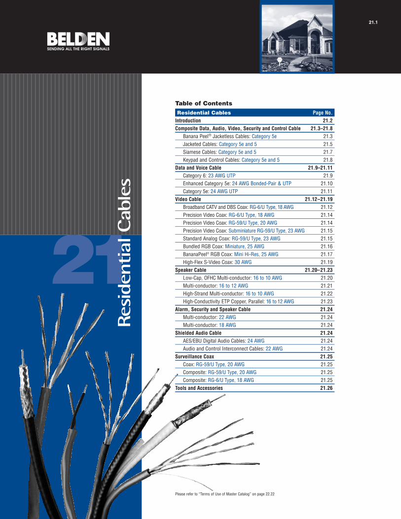
21
Please refer to “Terms of Use of Master Catalog” on page 22.22
Table of ContentsResidential Cables Page No.
Introduction 21.2Composite Data, Audio, Video, Security and Control Cable 21.3–21.8
Banana Peel® Jacketless Cables: Category 5e 21.3Jacketed Cables: Category 5e and 5 21.5Siamese Cables: Category 5e and 5 21.7Keypad and Control Cables: Category 5e and 5 21.8
Data and Voice Cable 21.9–21.11Category 6: 23 AWG UTP 21.9Enhanced Category 5e: 24 AWG Bonded-Pair & UTP 21.10Category 5e: 24 AWG UTP 21.11
Video Cable 21.12–21.19Broadband CATV and DBS Coax: RG-6/U Type, 18 AWG 21.12Precision Video Coax: RG-6/U Type, 18 AWG 21.14Precision Video Coax: RG-59/U Type, 20 AWG 21.14Precision Video Coax: Subminiature RG-59/U Type, 23 AWG 21.15Standard Analog Coax: RG-59/U Type, 23 AWG 21.15Bundled RGB Coax: Miniature, 25 AWG 21.16BananaPeel® RGB Coax: Mini Hi-Res, 25 AWG 21.17High-Flex S-Video Coax: 30 AWG 21.19
Speaker Cable 21.20–21.23Low-Cap, OFHC Multi-conductor: 16 to 10 AWG 21.20Multi-conductor: 16 to 12 AWG 21.21High-Strand Multi-conductor: 16 to 10 AWG 21.22High-Conductivity ETP Copper, Parallel: 16 to 12 AWG 21.23
Alarm, Security and Speaker Cable 21.24Multi-conductor: 22 AWG 21.24Multi-conductor: 18 AWG 21.24
Shielded Audio Cable 21.24AES/EBU Digital Audio Cables: 24 AWG 21.24Audio and Control Interconnect Cables: 22 AWG 21.24
Surveillance Coax 21.25Coax: RG-59/U Type, 20 AWG 21.25Composite: RG-59/U Type, 20 AWG 21.25Composite: RG-6/U Type, 18 AWG 21.25
Tools and Accessories 21.26
Res
iden
tial
Cab
les
21.1

R E S I D E N T I A L C A B L E S 21.2
IntroductionInnovative Home Cabling Solutions From the World’s Most Trusted Name in Cable
F o r m o r e i n f o r m a t i o n , c o n t a c t B e l d e n Te c h n i c a l S u p p o r t : 1 - 8 0 0 - B E L D E N - 1 • w w w . b e l d e n . c o m
Because we understand that each homeinstallation has its own set of needs andexpectations, Belden offers its structuredcabling line of individual, dual componentand composite cables — in all, over 50 different cables for your home automation,networking, security and entertainment system installations.
Belden Quality and Reliability
Belden manufactures all of the cables in its residential cable line so you can beassured that each cable product is theresult of the most rigorous quality processin the industry.
Belden’s commitment to quality and reliability is unequaled in its marketplace.And since we have such a wide range ofproducts to meet your varied needs,Belden can easily provide you with one-stop home shopping.
High-Performance, Easy-to-Install Cables
Individual or single application cables are available for any data, video, audio or security need, including:
Category 5e, Category 6 UTP and fiber data cables for multimedia, voice, video and data use
Series 6 and Series 59 video coaxcables for HDTV, DBS, CATV, S-Video,CCTV and cable modem applications
Speaker cables for your audio distribution needs
Paired, unshielded cables for security and alarm applications
Belden also offers over 20 different composite cables. Composite cables simplify a multiple use installation by combining Belden data cables, coaxialcables, paired and multi-conductor cables, and fiber optic cables in a single-pull product.
Time-tested and Preferred in Other Industries
Many of the Belden® Residential Cables inthis catalog have been long-standing leadersin other industries such as:
Computer networks — where Belden offers the most innovativecables and the leading data cable technology worldwide.
Broadcast — where network studiosprefer Belden over any other cable forpicture-perfect quality and professionalaudio technicians demand Belden forcrystal-clear audio quality.
Broadband CATV — where BeldenDuobond Plus® (Tri-shield) Cables haveconsistently outperformed the moreelaborate quad-shielded cables.
Alarm/Security — where Belden has been a favorite among installers for many years.
Now, these industry-leading and time-testedcables are available, along with many newinnovations, for wiring the home of the 21stCentury…only from Belden.
Better Designs, Better Performance
Some unique high performance technologiesare used in the manufacture of these various cables, including:
Belden’s Patented Data CableTechnology: Bonded-Pairs
To ensure top performance, Belden uses a unique manufacturing process that affixesthe individual insulated conductors of the pairs along their longitudinal axis. Thiscable construction feature prevents gapsfrom occurring between the conductorpairs: a critical factor in the electrical performance of the cable.
Only Belden Bonded-Pair Data Cables Offer the Assurance of Installable Performance™
Due to the patented Bonded-Pair design, these cables are able to withstand the rigors of a typical installation without any degradation in performance. This means that the Cat 5e cable that you purchase fromBelden to meet Cat 5e specifications will not only meet these specificationsbefore installation, but more importantly, it will meet them after installation.
Coax Cables with Belden’s Exclusive Duobond Plus® Shielding
Duobond Plus consists of a Duofoil® II (foil tape) surrounded by an 80 percentbraid and an outer layer of foil with a uniqueshorting fold. This unique construction provides optimum shielding effectiveness.
Composite Cables — Without a Jacket!
Belden Banana Peel® composite cablesfeature a patent-pending design that eliminates the need for an overall jacket, making these cables easy to handle, easy to identify, easy to pull and easy to terminate. Just peel the cables off the center spline, and you’re in business.
Everything You Need For The Intelligent Home
These structured cabling products for theIntelligent Home are all brought to you byBelden — the most innovative and trustedmanufacturer in the cable industry. Beldenoffers the most comprehensive, time-testedand proven products for cabling the home.
New Banana Peel composite cables feature a patent-pending design that eliminates the need for an overall jacket.

Composite • (2) Cat 5e 4-Bonded-Pair UTP 24 AWG • (2) Series 6 Coax w/Duobond Plus® (Bonded Tri-Shield)
Polyolefin Insulation (Pairs) • Gas-injected FPE Insulation (Coax) • F-R PVC Jackets • No Overall Jacket7876S NEC: 500 152.4 63.0 28.6 .550 13.97 (2) 4-Pair UTP None Polyolefin F-R PVC .204 5.18
CMR 1000 304.8 119.0 54.0 Data Cables: (see chart (1) BlueCEC: Cat 5e below) (1) Green
CMG FT4 Bonded-Pairs24 AWG(solid)
Bare Copper Cond.
(1700R style)
(2) Coax: Duobond Plus Gas-injected F-R PVC .275 6.99Series 6 (Bonded Foam (1) Black18 AWG Tri-Shield): Polyethylene (1) White(solid) Duobond® +
Bare Copper 77% AL BraidU.S. Patents 7,049,523; 5,606,151; 5,734,126. Cond. + AL Foil w/ Third party verified to TIA/EIA-568-B.2, Category 5e (7915A style) Shorting FoldCoax sweep tested to 3.0 GHz and jacket sequentially marked. 4.6Ω/M′Coax shield effectiveness 125dB @ 1GHz is better than Quad shield. 15.1Ω/km
Composite • (2) Cat 5e 4-Bonded-Pair UTP 24 AWG • (2) Series 6 Coax w/Duobond Plus • (1) 2-Fiber LANLite®
Polyolefin Insulation (Pairs) • Gas-injected FPE Insulation (Coax) • F-R PVC Jackets • No Overall Jacket7878S NEC: 500 152.4 71.5 32.4 .595 15.11 (2) 4-Pair UTP None Polyolefin F-R PVC .204 5.18
CMR OF 1000 304.8 137.0 62.1 Data Cables: (see chart (1) BlueCEC: Cat 5e below) (1) Green
CMG OF FT4 Bonded-Pairs24 AWG(solid)
Bare Copper Cond.(1700R style)
(2) Coax: Duobond Plus Gas-injected F-R PVC .275 6.99Series 6 (Bonded Foam (1) Black18 AWG Tri-Shield): Polyethylene (1) White(solid) Duobond +
Bare Copper 77% AL BraidCond. + AL Foil w/
(7915A style) Shorting Fold4.6Ω/M′
15.1Ω/km
(1) 2-Fiber None PVC F-R PVC .175 4.45LANLite: (1) Blue (1) Orange
U.S. Patents 7,049,523; 5,606,151; 5,734,126. Gigabit Ethernet (1) OrangeThird party verified to TIA/EIA-568-B.2, Category 5e 62.5µ/125µ/900µCoax sweep tested to 3.0 GHz and jacket sequentially marked. (core/clad/coating)Coax shield effectiveness 125dB @ 1GHz is better than Quad shield. Tight BufferedAL = Aluminum • BC = Bare Copper • DCR = DC Resistance • FPE = Foam Polyethylene • F-R = Flame-retardant • UTP = Unshielded Twisted Pair
Contact the Belden Customer Service Department for a Comprehensive Connector Cross Reference: 1-800-BELDEN-1.Request quotations of cables not listed.
R E S I D E N T I A L C A B L E S 21.3
Composite Data, Audio, Video, Security and Control CableBanana Peel® Jacketless CablesCategory 5e Bonded-Pairs
21•
Resi
dent
ialC
able
s
F o r m o r e i n f o r m a t i o n , c o n t a c t B e l d e n Te c h n i c a l S u p p o r t : 1 - 8 0 0 - B E L D E N - 1 • w w w . b e l d e n . c o m
InsulationMaterial &Color Code
Overall Nom. OD
Inch mm
ComponentNom. OD
Inch mm
ShieldingMaterials
& Nom. DCR
ComponentDescriptions
StandardUnit WeightStandard Lengths
Lbs. kgFt. m
UL NEC/C(UL) CEC
Type
PartNo.
ComponentJacket
Material& Colors
Description
Color Codes: Cat 5e UTP
Pair No. Color Combination1 White/Blue Stripe & Blue
2 White/Orange Stripe & Orange
3 White/Green Stripe & Green
4 White/Brown Stripe & Brown
Shorting FoldShorting Fold
Shorting FoldShorting Fold

R E S I D E N T I A L C A B L E S 21.4
F o r m o r e i n f o r m a t i o n , c o n t a c t B e l d e n Te c h n i c a l S u p p o r t : 1 - 8 0 0 - B E L D E N - 1 • w w w . b e l d e n . c o m
Composite Data, Audio, Video, Security and Control CableBanana Peel® Jacketless CablesCategory 5e
Composite • (1) Cat 5e 4-Pair UTP 24 AWG • (2) Series 6 Coax w/Duobond® IV* Quad Shield
Polyolefin Insulation (Pairs) • Gas-injected FPE Insulation (Coax) • PVC Jackets • No Overall Jacket7956S NEC: 500 152.4 59.0 26.8 .596 15.14 (2) 4-Pair UTP None Polyolefin PVC .194 4.93u CMR 1000 304.8 112.0 50.8 Data Cables: (see chart (1) Blue
CEC: Cat 5e below) (1) GreenCMG FT4 24 AWG
(solid)BC Cond.
(1583R style)
(2) Coax: Duobond IV Gas-injected PVC .298 7.57Series 6 Quad Shield: Foam (1) Black
U.S. Patent 7,049,523. 18 AWG 60% & 40% Polyethylene (1) WhiteThird party verified to TIA/EIA-568-B.2, Category 5e. (solid) AL BraidsCoax shield effectiveness 110dB @ 1GHz. BC Cond. 4.8Ω/M′Coax sweep tested to 3.0 GHz and jacket sequentially marked. (7916A style) 15.7Ω/km
Composite • (2) Cat 5e 4-Pair UTP 24 AWG • (2) Series 6 Coax w/Duobond IV* Quad Shield
Polyolefin Insulation (Pairs) • Gas-injected FPE Insulation (Coax) • F-R PVC Jackets • No Overall Jacket7913S NEC: 500 152.4 68.5 31.1 .600 15.24 (2) 4-Pair UTP None Polyolefin F-R PVC .194 4.93
CMR 1000 304.8 130.0 59.0 Data Cables: (see chart (1) BlueCEC: Cat 5e below) (1) Green
CMG FT4 24 AWG (solid)
BC Cond. (1583R style)
(2) Coax: Duobond IV Gas-injected F-R PVC .298 7.57Series 6 Quad Shield: Foam (1) Black
U.S. Patent 7,049,523. 18 AWG 60% & 40% Polyethylene (1) WhiteThird party verified to TIA/EIA-568-B.2, Category 5e. (solid) AL BraidsCoax shield effectiveness 110dB @ 1GHz. BC Cond. 4.8Ω/M′Coax sweep tested to 3.0 GHz and jacket sequentially marked. (7916A style) 15.7Ω/km
Composite • (2) Cat 5e 4-Pair UTP 24 AWG • (2) Series 6 Coax w/Duobond IV* Quad Shield • (1) 2-Fiber LANLite®
Polyolefin Insulation (Pairs) • Gas-injected FPE Insulation (Coax) • F-R PVC Jackets • No Overall Jacket7914S NEC: 500 152.4 77.0 34.9 .625 15.88 (2) 4-Pair UTP None Polyolefin F-R PVC .194 4.93
CMR OF 1000 304.8 148.0 67.1 Data Cables: (see chart (1) BlueCEC: Cat 5e below) (1) Green
CMG OF FT4 24 AWG(solid)
BC Cond. (1583R style)
(2) Coax: Duobond IV Gas-injected F-R PVC .298 7.57Series 6 Quad Shield: Foam (1) Black18 AWG 60% & 40% Polyethylene (1) White(solid) AL Braids
BC Cond. 4.8Ω/M′(7916A style) 15.7Ω/km
(1) 2-Fiber None PVC F-R PVC .175 4.45LANLite: (1) Blue (1) Orange
U.S. Patent 7,049,523. Gigabit Ethernet (1) OrangeThird party verified to TIA/EIA-568-B.2, Category 5e. 62.5µ/125µ/900µCoax shield effectiveness 110dB @ 1GHz. (core/clad/coating)Coax sweep tested to 3.0 GHz and jacket sequentially marked. Tight BufferedAL = Aluminum • BC = Bare Copper • DCR = DC Resistance • FPE = Foam Polyethylene • F-R = Flame-retardant • UTP = Unshielded Twisted Pair
Contact the Belden Customer Service Department for a Comprehensive Connector Cross Reference: 1-800-BELDEN-1.Request quotations of cables not listed.
*Duobond IV = Duobond II + 60% aluminum braid + Duofoil® + 40% aluminum braid.
InsulationMaterial &Color Code
Overall Nom. OD
Inch mm
ComponentNom. OD
Inch mm
ShieldingMaterials
& Nom. DCR
ComponentDescriptions
StandardUnit WeightStandard Lengths
Lbs. kgFt. m
UL NEC/C(UL) CEC
Type
PartNo.
ComponentJacket
Material& Colors
Description
Color Codes: Cat 5e UTP
Pair No. Color Combination1 White/Blue Stripe & Blue
2 White/Orange Stripe & Orange
3 White/Green Stripe & Green
4 White/Brown Stripe & Brown
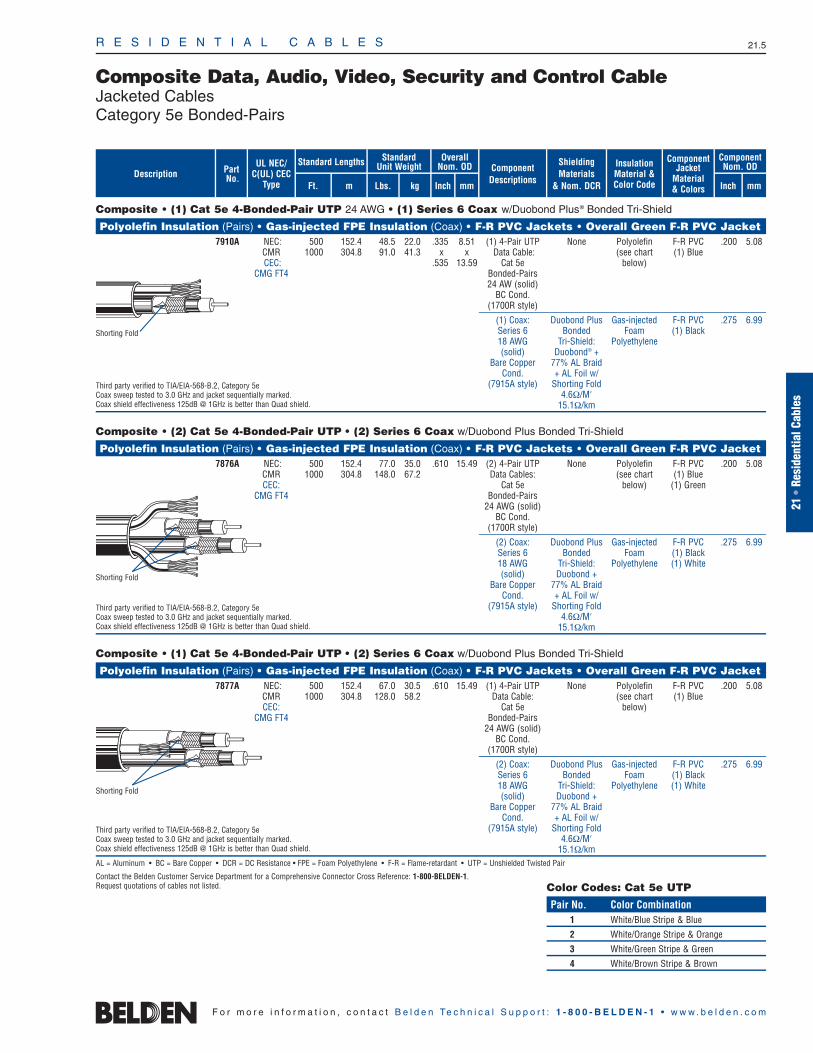
Composite • (1) Cat 5e 4-Bonded-Pair UTP 24 AWG • (1) Series 6 Coax w/Duobond Plus® Bonded Tri-Shield
Polyolefin Insulation (Pairs) • Gas-injected FPE Insulation (Coax) • F-R PVC Jackets • Overall Green F-R PVC Jacket 7910A NEC: 500 152.4 48.5 22.0 .335 8.51 (1) 4-Pair UTP None Polyolefin F-R PVC .200 5.08
CMR 1000 304.8 91.0 41.3 x x Data Cable: (see chart (1) BlueCEC: .535 13.59 Cat 5e below)
CMG FT4 Bonded-Pairs24 AW (solid)
BC Cond.(1700R style)
(1) Coax: Duobond Plus Gas-injected F-R PVC .275 6.99Series 6 Bonded Foam (1) Black18 AWG Tri-Shield: Polyethylene(solid) Duobond® +
Bare Copper 77% AL Braid Cond. + AL Foil w/
Third party verified to TIA/EIA-568-B.2, Category 5e (7915A style) Shorting FoldCoax sweep tested to 3.0 GHz and jacket sequentially marked. 4.6Ω/M′Coax shield effectiveness 125dB @ 1GHz is better than Quad shield. 15.1Ω/km
Composite • (2) Cat 5e 4-Bonded-Pair UTP • (2) Series 6 Coax w/Duobond Plus Bonded Tri-Shield
Polyolefin Insulation (Pairs) • Gas-injected FPE Insulation (Coax) • F-R PVC Jackets • Overall Green F-R PVC Jacket 7876A NEC: 500 152.4 77.0 35.0 .610 15.49 (2) 4-Pair UTP None Polyolefin F-R PVC .200 5.08
CMR 1000 304.8 148.0 67.2 Data Cables: (see chart (1) BlueCEC: Cat 5e below) (1) Green
CMG FT4 Bonded-Pairs24 AWG (solid)
BC Cond. (1700R style)
(2) Coax: Duobond Plus Gas-injected F-R PVC .275 6.99Series 6 Bonded Foam (1) Black18 AWG Tri-Shield: Polyethylene (1) White(solid) Duobond +
Bare Copper 77% AL Braid Cond. + AL Foil w/
Third party verified to TIA/EIA-568-B.2, Category 5e (7915A style) Shorting FoldCoax sweep tested to 3.0 GHz and jacket sequentially marked. 4.6Ω/M′Coax shield effectiveness 125dB @ 1GHz is better than Quad shield. 15.1Ω/km
Composite • (1) Cat 5e 4-Bonded-Pair UTP • (2) Series 6 Coax w/Duobond Plus Bonded Tri-Shield
Polyolefin Insulation (Pairs) • Gas-injected FPE Insulation (Coax) • F-R PVC Jackets • Overall Green F-R PVC Jacket 7877A NEC: 500 152.4 67.0 30.5 .610 15.49 (1) 4-Pair UTP None Polyolefin F-R PVC .200 5.08
CMR 1000 304.8 128.0 58.2 Data Cable: (see chart (1) BlueCEC: Cat 5e below)
CMG FT4 Bonded-Pairs24 AWG (solid)
BC Cond. (1700R style)
(2) Coax: Duobond Plus Gas-injected F-R PVC .275 6.99Series 6 Bonded Foam (1) Black18 AWG Tri-Shield: Polyethylene (1) White(solid) Duobond +
Bare Copper 77% AL BraidCond. + AL Foil w/
Third party verified to TIA/EIA-568-B.2, Category 5e (7915A style) Shorting FoldCoax sweep tested to 3.0 GHz and jacket sequentially marked. 4.6Ω/M′Coax shield effectiveness 125dB @ 1GHz is better than Quad shield. 15.1Ω/kmAL = Aluminum • BC = Bare Copper • DCR = DC Resistance • FPE = Foam Polyethylene • F-R = Flame-retardant • UTP = Unshielded Twisted Pair
Contact the Belden Customer Service Department for a Comprehensive Connector Cross Reference: 1-800-BELDEN-1.Request quotations of cables not listed.
InsulationMaterial &Color Code
Overall Nom. OD
Inch mm
ComponentNom. OD
Inch mm
ShieldingMaterials
& Nom. DCR
ComponentDescriptions
StandardUnit WeightStandard Lengths
Lbs. kgFt. m
UL NEC/C(UL) CEC
Type
PartNo.
ComponentJacket
Material& Colors
Description
Color Codes: Cat 5e UTP
Pair No. Color Combination1 White/Blue Stripe & Blue
2 White/Orange Stripe & Orange
3 White/Green Stripe & Green
4 White/Brown Stripe & Brown
R E S I D E N T I A L C A B L E S 21.5
Composite Data, Audio, Video, Security and Control CableJacketed CablesCategory 5e Bonded-Pairs
21•
Resi
dent
ialC
able
s
F o r m o r e i n f o r m a t i o n , c o n t a c t B e l d e n Te c h n i c a l S u p p o r t : 1 - 8 0 0 - B E L D E N - 1 • w w w . b e l d e n . c o m
Shorting Fold
Shorting Fold
Shorting Fold

Composite • (2) Cat 5e 4-Bonded-Pair UTP 24 AWG • (2) Series 6 Coax w/Duobond Plus® Tri-Shield • (1) 2-Fiber LANLite®
Polyolefin Insulation (Pairs) • Gas-injected FPE Insulation (Coax) • F-R PVC Jackets • Overall Green F-R PVC Jacket 7878A NEC: 500 152.4 84.0 34.2 .635 16.13 (2) 4-Pair UTP None Polyolefin F-R PVC .200 5.08
CMR OF 1000 304.8 162.0 73.5 Data Cables: (see chart (1) BlueCEC: Cat 5e Bonded-Pairs below) (1) Green
CMG OF FT4 24 AWG (solid)BC Cond.
(1700R style)
(2) Coax: Duobond Plus Gas-injected F-R PVC .275 6.99Series 6 Bonded Foam (1) Black18 AWG Tri-Shield: Polyethylene (1) White(solid) Duobond® +
Bare Copper 77% AL BraidCond. + AL Foil w/
(7915A style) Shorting Fold4.6Ω/M′
15.1Ω/km
(1) 2-Fiber None PVC F-R PVC .175 4.45LANLite: (1) Blue (1) Orange
Gigabit Ethernet (1) OrangeThird party verified to TIA/EIA-568-B.2, Category 5e 62.5µ/125µ/900µCoax sweep tested to 3.0 GHz and jacket sequentially marked. (core/clad/coating)Coax shield effectiveness 125dB @ 1GHz is better than Quad shield. Tight Buffered
Composite • (2) Cat 5 4-Pair UTP 24 AWG • (2) Series 6 Coax w/Duobond IV* Quad Shield
Polyolefin Insulation (Pairs) • Gas-injected FPE Insulation (Coax) • F-R PVC Jackets • Overall Green F-R PVC Jacket 7913A NEC: 500 152.4 82.0 37.2 .660 16.76 (2) 4-Pair UTP None Polyolefin F-R PVC .195 4.95
CMR 1000 304.8 157.0 71.3 Data Cables: (see chart (1) BlueCEC: Cat 5e below) (1) Green
CMG FT4 24 AWG (solid)BC Cond.
(1583R style)
(2) Coax: Duobond IV Gas-injected F-R PVC .298 7.57Series 6 Quad Shield: Foam (1) Black18 AWG 60% & 40% Polyethylene (1) White
Third party verified to TIA/EIA-568-B.2, Category 5e (solid) AL BraidsCoax sweep tested to 3.0 GHz and jacket sequentially marked. BC Cond. 4.8Ω/M′Coax shield effectiveness 110dB @ 1GHz. (7916A style) 15.7Ω/km
Composite • (2) Cat 5 4-Pair UTP 24 AWG • (2) Series 6 Coax w/Duobond IV* Quad Shield • (1) 2-Fiber LANLitePolyolefin Insulation (Pairs) • Gas-injected FPE Insulation (Coax) • F-R PVC Jackets • Overall Green F-R PVC Jacket
7914A NEC: 500 152.4 88.0 40.0 .660 16.76 (2) 4-Pair UTP None Polyolefin F-R PVC .195 4.95CMR OF 1000 304.8 169.0 76.7 Data Cables: (see chart (1) Blue
CEC: Cat 5e below) (1) GreenCMG OF FT4 24 AWG (solid)
BC Cond.(1583R style)
(2) Coax: Duobond IV Gas-injected F-R PVC .298 7.57Series 6 Quad Shield: Foam (1) Black18 AWG 60% & 40% Polyethylene (1) White(solid) AL Braids
BC Cond. 4.8Ω/M′(7916A style) 15.7Ω/km
(1) 2-Fiber None PVC F-R PVC .175 4.45LANLite: (1) Blue (1) Orange
Gigabit Ethernet (1) OrangeThird party verified to TIA/EIA-568-B.2, Category 5e 62.5µ/125µ/900µCoax sweep tested to 2.25 GHz and jacket sequentially marked. (core/clad/coating)Coax shield effectiveness 110dB @ 1GHz. Tight BufferedAL = Aluminum • BC = Bare Copper • DCR = DC Resistance • FPE = Foam Polyethylene • F-R = Flame-retardant • UTP = Unshielded Twisted Pair
Contact the Belden Customer Service Department for a Comprehensive Connector Cross Reference: 1-800-BELDEN-1.Request quotations of cables not listed.
*Duobond IV = Duobond II + 60% aluminum braid + Duofoil® + 40% aluminum braid.
InsulationMaterial &Color Code
Overall Nom. OD
Inch mm
ComponentNom. OD
Inch mm
ShieldingMaterials
& Nom. DCR
ComponentDescriptions
StandardUnit WeightStandard Lengths
Lbs. kgFt. m
UL NEC/C(UL) CEC
Type
PartNo.
ComponentJacket
Material& Colors
Description
R E S I D E N T I A L C A B L E S 21.6
Composite Data, Audio, Video, Security and Control CableJacketed CablesCategory 5e Bonded-Pairs and Category 5
F o r m o r e i n f o r m a t i o n , c o n t a c t B e l d e n Te c h n i c a l S u p p o r t : 1 - 8 0 0 - B E L D E N - 1 • w w w . b e l d e n . c o m
Color Code: Cat 5e UTP
Pair No. Color Combination1 White/Blue Stripe & Blue2 White/Orange Stripe & Orange3 White/Green Stripe & Green4 White/Brown Stripe & Brown
Shorting Fold

Composite • (1) Cat 5e 4-Bonded-Pair UTP 24 AWG • (1) Series 6 Coax w/Duobond Plus® Bonded Tri-Shield
Polyolefin Insulation (Pairs) • Gas-injected FPE Insulation (Coax) • Overall Green F-R PVC JacketSiamese Construction 7911A NEC: 500 152.4 35.0 15.9 .275 6.99 (1) 4-Pair UTP None Polyolefin
CMR 1000 304.8 60.0 27.2 x x Data Cables: (see chartCEC: .529 13.44 Cat 5e below)
CMG FT4 Bonded-Pairs24 AWG(solid)
BC Cond.(1700R style)
(1) Coax: Duobond Plus Gas-injectedSeries 6 Bonded Foam18 AWG Tri-Shield: Polyethylene(solid) Duobond® +
Bare Copper 77% AL BraidCond. + AL Foil w/
Third party verified to TIA/EIA-568-B.2, Category 5e (7915A style) Shorting FoldCoax sweep tested to 3.0 GHz and jacket sequentially marked. 4.6Ω/M′Coax shield effectiveness 125dB @ 1GHz is better than Quad shield. 5.1Ω/km
Composite • (1) Cat 5 4-Pair UTP 24 AWG • (1) Series 6 Coax w/Duobond IV* Quad Shield
Polyolefin Insulation (Pairs) • Gas-injected FPE Insulation (Coax) • Overall Green F-R PVC Jacket Siamese Construction 7912A NEC: 500 152.4 37.5 17.0 .297 7.54 (1) 4-Pair UTP None Polyolefin
CMR 1000 304.8 65.0 29.5 x x Data Cables: (see chartCEC: .543 13.79 Cat 5e below)
CMG FT4 24 AWG(solid)
BC Cond. (1583R style)
(1) Coax: Duobond IV Gas-injectedSeries 6 Quad Shield: Foam18 AWG 60% & 40% Polyethylene
Third party verified to TIA/EIA-568-B.2, Category 5e (solid) AL BraidsCoax sweep tested to 3.0 GHz and jacket sequentially marked. BC Cond. 4.8Ω/M′Coax shield effectiveness 110dB @ 1GHz. (7916A style) 15.7Ω/km
Composite • (1) Cat 5 4-Pair UTP 24 AWG • (1) Series 6 Coax w/Duobond II* Foil + Braid Shield
Polyolefin Insulation (Pairs) • Gas-injected Foam HDPE Insulation (Coax) • Overall Green F-R PVC Jacket Siamese Construction 7917A NEC: 1000 304.8 55.0 25.0 .273 6.93 (1) 4-Pair UTP None Polyolefin
CM x x Data Cables: (see chartCEC: .504 12.80 Cat 5e below)CM 24 AWG
(solid)BC Cond.
(1583R style)
(1) Coax: Duobond II: Gas-injectedSeries 6 Bonded Foil Foam18 AWG (100%) + High-density(solid) AL Braid Polyethylene
Bare Copper (57%)Third party verified to TIA/EIA-568-B.2, Category 5e Cond. 9.0Ω/M′Coax sweep tested to 3.0 GHz and jacket sequentially marked. 29.5Ω/kmAL = Aluminum • BC = Bare Copper • DCR = DC Resistance • FPE = Foam Polyethylene • F-R = Flame-retardant • HDPE = High-Density Polyethylene • UTP = Unshielded Twisted Pair
Contact the Belden Customer Service Department for a Comprehensive Connector Cross Reference: 1-800-BELDEN-1.Request quotations of cables not listed.
*Duobond IV = Duobond II + 60% aluminum braid + Duofoil® + 40% aluminum braid.
InsulationMaterial &Color Code
Overall Nom. OD
Inch mm
ShieldingMaterials
& Nom. DCR
ComponentDescriptions
StandardUnit WeightStandard Lengths
Lbs. kgFt. m
UL NEC/C(UL) CEC
Type
PartNo.Description
R E S I D E N T I A L C A B L E S 21.7
Composite Data, Audio, Video, Security and Control CableSiamese CablesCategory 5e Bonded-Pairs and Category 5
21•
Resi
dent
ialC
able
s
F o r m o r e i n f o r m a t i o n , c o n t a c t B e l d e n Te c h n i c a l S u p p o r t : 1 - 8 0 0 - B E L D E N - 1 • w w w . b e l d e n . c o m
Color Code: Cat 5e UTP
Pair No. Color Combination
1 White/Blue Stripe & Blue
2 White/Orange Stripe & Orange
3 White/Green Stripe & Green
4 White/Brown Stripe & Brown
Shorting Fold
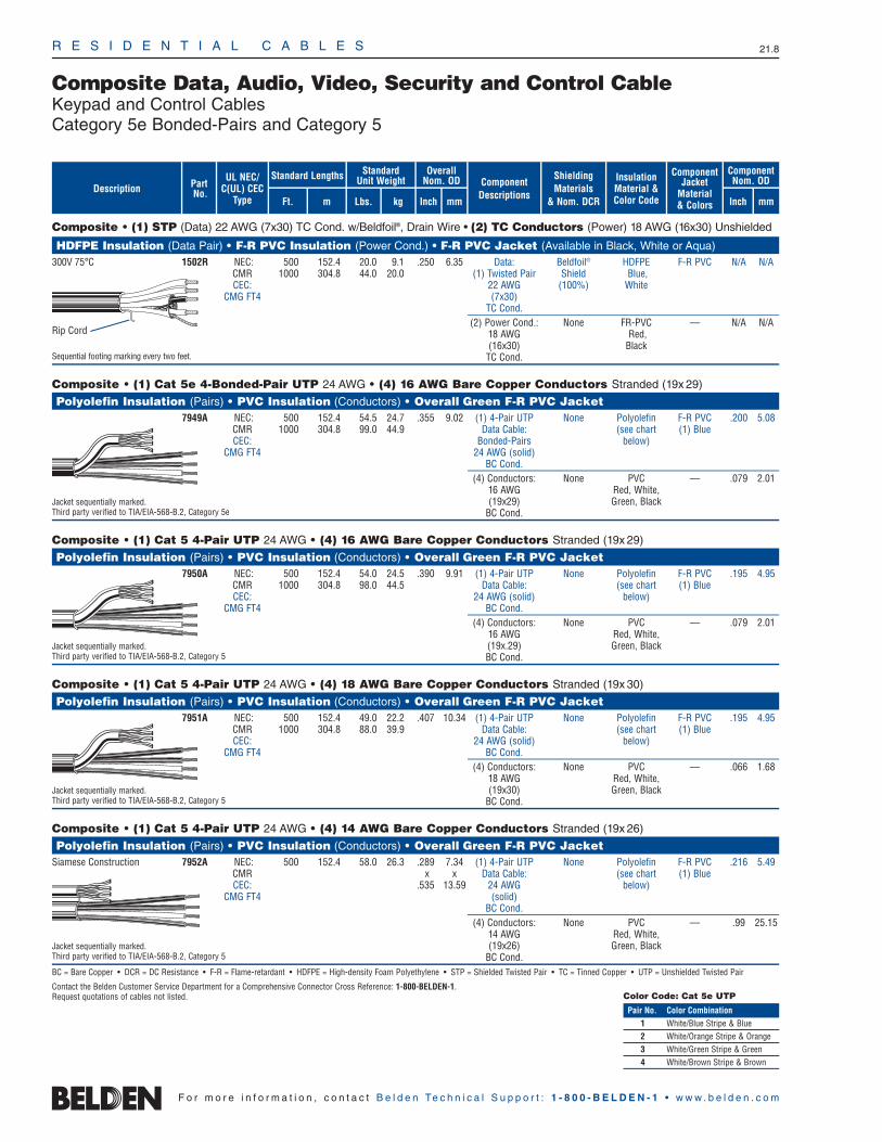
R E S I D E N T I A L C A B L E S 21.8
F o r m o r e i n f o r m a t i o n , c o n t a c t B e l d e n Te c h n i c a l S u p p o r t : 1 - 8 0 0 - B E L D E N - 1 • w w w . b e l d e n . c o m
Composite Data, Audio, Video, Security and Control CableKeypad and Control CablesCategory 5e Bonded-Pairs and Category 5
Composite • (1) STP (Data) 22 AWG (7x30) TC Cond. w/Beldfoil®, Drain Wire • (2) TC Conductors (Power) 18 AWG (16x30) Unshielded
HDFPE Insulation (Data Pair) • F-R PVC Insulation (Power Cond.) • F-R PVC Jacket (Available in Black, White or Aqua)300V 75°C 1502R NEC: 500 152.4 20.0 9.1 .250 6.35 Data: Beldfoil® HDFPE F-R PVC N/A N/A
CMR 1000 304.8 44.0 20.0 (1) Twisted Pair Shield Blue,CEC: 22 AWG (100%) White
CMG FT4 (7x30)TC Cond.
(2) Power Cond.: None FR-PVC — N/A N/A18 AWG Red,(16x30) Black
Sequential footing marking every two feet. TC Cond.
Composite • (1) Cat 5e 4-Bonded-Pair UTP 24 AWG • (4) 16 AWG Bare Copper Conductors Stranded (19x 29)
Polyolefin Insulation (Pairs) • PVC Insulation (Conductors) • Overall Green F-R PVC Jacket 7949A NEC: 500 152.4 54.5 24.7 .355 9.02 (1) 4-Pair UTP None Polyolefin F-R PVC .200 5.08
CMR 1000 304.8 99.0 44.9 Data Cable: (see chart (1) BlueCEC: Bonded-Pairs below)
CMG FT4 24 AWG (solid)BC Cond.
(4) Conductors: None PVC — .079 2.0116 AWG Red, White,
Jacket sequentially marked. (19x29) Green, BlackThird party verified to TIA/EIA-568-B.2, Category 5e BC Cond.
Composite • (1) Cat 5 4-Pair UTP 24 AWG • (4) 16 AWG Bare Copper Conductors Stranded (19x 29)
Polyolefin Insulation (Pairs) • PVC Insulation (Conductors) • Overall Green F-R PVC Jacket 7950A NEC: 500 152.4 54.0 24.5 .390 9.91 (1) 4-Pair UTP None Polyolefin F-R PVC .195 4.95
CMR 1000 304.8 98.0 44.5 Data Cable: (see chart (1) BlueCEC: 24 AWG (solid) below)
CMG FT4 BC Cond.(4) Conductors: None PVC — .079 2.01
16 AWG Red, White,Jacket sequentially marked. (19x.29) Green, BlackThird party verified to TIA/EIA-568-B.2, Category 5 BC Cond.
Composite • (1) Cat 5 4-Pair UTP 24 AWG • (4) 18 AWG Bare Copper Conductors Stranded (19x 30)
Polyolefin Insulation (Pairs) • PVC Insulation (Conductors) • Overall Green F-R PVC Jacket 7951A NEC: 500 152.4 49.0 22.2 .407 10.34 (1) 4-Pair UTP None Polyolefin F-R PVC .195 4.95
CMR 1000 304.8 88.0 39.9 Data Cable: (see chart (1) BlueCEC: 24 AWG (solid) below)
CMG FT4 BC Cond.(4) Conductors: None PVC — .066 1.68
18 AWG Red, White,Jacket sequentially marked. (19x30) Green, BlackThird party verified to TIA/EIA-568-B.2, Category 5 BC Cond.
Composite • (1) Cat 5 4-Pair UTP 24 AWG • (4) 14 AWG Bare Copper Conductors Stranded (19x 26)
Polyolefin Insulation (Pairs) • PVC Insulation (Conductors) • Overall Green F-R PVC Jacket Siamese Construction 7952A NEC: 500 152.4 58.0 26.3 .289 7.34 (1) 4-Pair UTP None Polyolefin F-R PVC .216 5.49
CMR x x Data Cable: (see chart (1) BlueCEC: .535 13.59 24 AWG below)
CMG FT4 (solid)BC Cond.
(4) Conductors: None PVC — .99 25.1514 AWG Red, White,
Jacket sequentially marked. (19x26) Green, BlackThird party verified to TIA/EIA-568-B.2, Category 5 BC Cond.BC = Bare Copper • DCR = DC Resistance • F-R = Flame-retardant • HDFPE = High-density Foam Polyethylene • STP = Shielded Twisted Pair • TC = Tinned Copper • UTP = Unshielded Twisted Pair
Contact the Belden Customer Service Department for a Comprehensive Connector Cross Reference: 1-800-BELDEN-1.Request quotations of cables not listed.
InsulationMaterial &Color Code
Overall Nom. OD
Inch mm
ComponentNom. OD
Inch mm
ShieldingMaterials
& Nom. DCR
ComponentDescriptions
StandardUnit WeightStandard Lengths
Lbs. kgFt. m
UL NEC/C(UL) CEC
Type
PartNo.
ComponentJacket
Material& Colors
Description
Color Code: Cat 5e UTP
Pair No. Color Combination1 White/Blue Stripe & Blue2 White/Orange Stripe & Orange3 White/Green Stripe & Green4 White/Brown Stripe & Brown
Rip Cord

23 AWG Solid Bare Copper Conductors • Twisted Pairs • Central Rod Filler • Rip Cord • See Color Code Chart (below)
Non-Plenum • Polyolefin Insulation • PVC Jacket (Available in Red, Orange, Yellow, Green, Blue, Purple, Gray, White or Black)75°C 7881A NEC: 4 1000 304.8 30.0 13.6 .235 5.97 8.2 5.0 330
CMR A-1000 A-304.8 33.0 15.0CEC:
CMR FT4
Jacket sequentially marked at 2 ft. intervals.Third party verified to TIA/EIA-568-B.2-1, Category 6
Plenum • FRPO/FEP Insulation • Flamarrest® Jacket (Red, Orange, Yellow, Green, Blue, Purple, Gray, White, Natural or Black)75°C 7882A NEC: 4 1000 304.8 29.0 13.2 .224 5.69 8.2 5.0 330
CMP A-1000 A-304.8 32.0 14.5CEC:
CMP FT6
Jacket sequentially marked at 2 ft. intervals.Third party verified to TIA/EIA-568-B.2-1, Category 6
ACR = Attenuation Crosstalk Ratio • DCR = DC Resistance • ELFEXT = Equal Level Far-end Crosstalk • FEP = Fluorinated Ethylene-Propylene • FRPO = Flame-retardant Polyolefin • NEXT = Near-end Crosstalk •PSUM = Power Sum • RL = Return Loss • UTP = Unshielded Twisted Pair(s)
For a complete selection of Belden® Data Cables, refer to the Commercial Networking: Copper section of this catalog.
R E S I D E N T I A L C A B L E S 21.9
Data and Voice CableCategory 6 UTP Cables
21•
Resi
dent
ialC
able
s
F o r m o r e i n f o r m a t i o n , c o n t a c t B e l d e n Te c h n i c a l S u p p o r t : 1 - 8 0 0 - B E L D E N - 1 • w w w . b e l d e n . c o m
PartNo.Description
Nominal OD
Inch mm
Standard Lengths
Ft. m
No.of
Pairs
StandardUnit Wt.
Lbs. kg
UL NEC/C(UL) CEC
Type
Max.DCR(Ω/
100m)
Max.DCR
Unbal.(%)
Max.Cap.
Unbal.(pF/
100m)
Freq.(MHz)
Max.Atten.(dB/
100m)
Min.PSUMNEXT(dB)
Min.PSUMACR(dB/100m)
Min.PSUM
ELFEXT(dB/100m)
InputImped.
(Ω)
Min.RL(dB)
Color Codes
Pair No. Color Combination1 White/Blue Stripe & Blue
2 White/Orange Stripe & Orange
3 White/Green Stripe & Green
4 White/Brown Stripe & Brown
Rip Cord
Rip Cord
11020
31.2562.5100200250
2.06.08.5
10.715.419.829.032.8
72.357.352.849.945.442.337.836.3
70.351.344.339.230.022.58.83.5
64.844.838.734.928.824.818.716.8
100±15100±15100±15100±15100±15100±15100±22100±32
20.025.025.023.621.520.118.017.3
11020
31.2562.5100200250
2.06.08.5
10.715.419.829.032.8
72.357.352.849.945.442.337.836.3
70.351.344.339.230.022.58.83.5
64.844.838.734.928.824.818.716.8
100±15100±15100±15100±15100±15100±15100±22100±32
20.025.025.023.621.520.118.017.3

24 AWG Bonded-Pairs Solid Bare Copper Conductors • Rip Cord • See Color Code Chart (below)
Non-Plenum • Polyolefin Insulation • PVC Jacket (Red, Orange, White, Yellow, Green, Blue, Purple, or Gray)80°C 1700R NEC: 4 U-1000 U-304.8 21.0 9.5 .204 5.18 9.0 3.0 66.0
CMR 1000 304.8 22.0 10.0CEC: 3000 914.4 63.0 28.6
CMR FT4
Jacket sequentially marked at 2 ft. intervals.Third party verified to TIA/EIA-568-B.2, Category 5e • U.S. Patents 5,606,151 and 5,734,1263000 ft. put-up not available in Orange, Yellow nor Green.
Plenum • FEP Insulation • Flamarrest® Jacket (Red, Orange, Yellow, Green, Blue, Purple, Gray, White, Natural or Black)75°C 1701A NEC: 4 U-1000 U-304.8 23.0 10.5 .193 4.90 9.0 3.0 66.0
CMP 1000 304.8 24.0 10.9CEC: 3000 914.4 69.0 31.3
CMP FT6
Jacket sequentially marked at 2 ft. intervals.Third party verified to TIA/EIA-568-B.2, Category 5e • U.S. Patents 5,606,151 and 5,734,1263000 ft. put-up available in Blue or Natural only.
24 AWG Solid Bare Copper Conductors • Twisted Pairs • Rip Cord • See Color Code Chart (below)
Non-Plenum • Polyolefin Insulation • PVC Jacket (Available in Red, Orange, Yellow, Green, White, Blue or Gray)80°C 1500R NEC: 4 1000 304.8 24.0 10.9 .194 4.93 9.0 3.0 66.0
CMR A-1000 A-304.8 27.0 12.3CEC:
CMR FT4
Jacket sequentially marked at 2 ft. intervals.Third party verified to TIA/EIA-568-B.2, Category 5e
ACR = Attenuation Crosstalk Ratio • DCR = DC Resistance • ELFEXT = Equal Level Far-end Crosstalk • FEP = Fluorinated Ethylene-Propylene • NEXT = Near-end Crosstalk • PSUM = Power Sum •RL = Return Loss • UTP = Unshielded Twisted Pair(s)
For a complete selection of Belden® Data Cables, refer to the Commercial Networking: Copper section of this catalog.
Tested to 350 MHz.
R E S I D E N T I A L C A B L E S 21.10
F o r m o r e i n f o r m a t i o n , c o n t a c t B e l d e n Te c h n i c a l S u p p o r t : 1 - 8 0 0 - B E L D E N - 1 • w w w . b e l d e n . c o m
Data and Voice CableEnhanced Category 5e UTP Cables
Tested to 350 MHz.
Color Codes
Pair No. Color Combination1 White/Blue Stripe & Blue
2 White/Orange Stripe & Orange
3 White/Green Stripe & Green
4 White/Brown Stripe & Brown
Rip Cord
Rip Cord
Tested to 350 MHz.Rip Cord
148
101625
31.2562.5100155200250350
2.04.05.76.48.1
10.311.616.821.727.732.036.444.3
65.356.351.850.347.344.342.938.435.332.530.829.327.2
63.352.346.143.939.134.131.321.617.14.73.0——
60.848.742.740.836.732.830.924.820.816.914.712.89.9
100±12100±12100±12100±12100±12100±15100±15100±15100±15100±18100±20100±20100±22
20.023.024.525.025.024.323.621.520.119.019.018.017.0
PartNo.Description
Nominal OD
Inch mm
Standard Lengths
Ft. m
No.of
Pairs
StandardUnit Wt.
Lbs. kg
UL NEC/C(UL) CEC
Type
Max.DCR(Ω/
100m)
Max.DCR
Unbal.(%)
Max.Cap.
Unbal.(pF/
100m)
Freq.(MHz)
Max.Atten.(dB/
100m)
Min.PSUMNEXT(dB)
Min.PSUMACR(dB/100m)
Min.PSUM
ELFEXT(dB/100m)
InputImped.
(Ω)
Min.RL(dB)
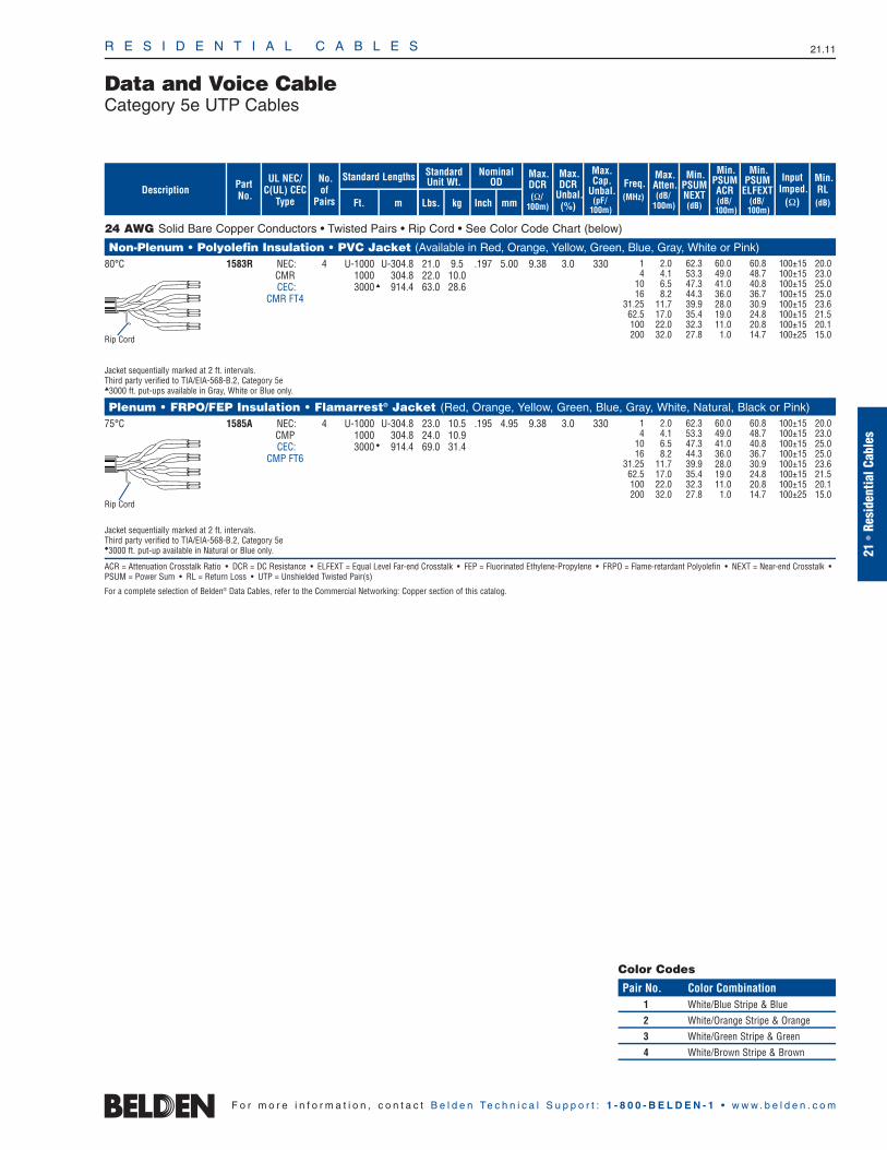
24 AWG Solid Bare Copper Conductors • Twisted Pairs • Rip Cord • See Color Code Chart (below)
Non-Plenum • Polyolefin Insulation • PVC Jacket (Available in Red, Orange, Yellow, Green, Blue, Gray, White or Pink)80°C 1583R NEC: 4 U-1000 U-304.8 21.0 9.5 .197 5.00 9.38 3.0 330
CMR 1000 304.8 22.0 10.0CEC: 3000 914.4 63.0 28.6
CMR FT4
Jacket sequentially marked at 2 ft. intervals.Third party verified to TIA/EIA-568-B.2, Category 5e3000 ft. put-ups available in Gray, White or Blue only.
Plenum • FRPO/FEP Insulation • Flamarrest® Jacket (Red, Orange, Yellow, Green, Blue, Gray, White, Natural, Black or Pink)75°C 1585A NEC: 4 U-1000 U-304.8 23.0 10.5 .195 4.95 9.38 3.0 330
CMP 1000 304.8 24.0 10.9CEC: 3000 914.4 69.0 31.4
CMP FT6
Jacket sequentially marked at 2 ft. intervals.Third party verified to TIA/EIA-568-B.2, Category 5e3000 ft. put-up available in Natural or Blue only.
ACR = Attenuation Crosstalk Ratio • DCR = DC Resistance • ELFEXT = Equal Level Far-end Crosstalk • FEP = Fluorinated Ethylene-Propylene • FRPO = Flame-retardant Polyolefin • NEXT = Near-end Crosstalk •PSUM = Power Sum • RL = Return Loss • UTP = Unshielded Twisted Pair(s)
For a complete selection of Belden® Data Cables, refer to the Commercial Networking: Copper section of this catalog.
R E S I D E N T I A L C A B L E S 21.11
21•
Resi
dent
ialC
able
s
F o r m o r e i n f o r m a t i o n , c o n t a c t B e l d e n Te c h n i c a l S u p p o r t : 1 - 8 0 0 - B E L D E N - 1 • w w w . b e l d e n . c o m
Data and Voice CableCategory 5e UTP Cables
Color Codes
Pair No. Color Combination1 White/Blue Stripe & Blue
2 White/Orange Stripe & Orange
3 White/Green Stripe & Green
4 White/Brown Stripe & Brown
Rip Cord
Rip Cord
14
1016
31.2562.5100200
2.04.16.58.2
11.717.022.032.0
62.353.347.344.339.935.432.327.8
60.049.041.036.028.019.011.01.0
60.848.740.836.730.924.820.814.7
100±15100±15100±15100±15100±15100±15100±15100±25
20.023.025.025.023.621.520.115.0
14
1016
31.2562.5100200
2.04.16.58.2
11.717.022.032.0
62.353.347.344.339.935.432.327.8
60.049.041.036.028.019.011.01.0
60.848.740.836.730.924.820.814.7
100±15100±15100±15100±15100±15100±15100±15100±25
20.023.025.025.023.621.520.115.0
PartNo.Description
Nominal OD
Inch mm
Standard Lengths
Ft. m
No.of
Pairs
StandardUnit Wt.
Lbs. kg
UL NEC/C(UL) CEC
Type
Max.DCR(Ω/
100m)
Max.DCR
Unbal.(%)
Max.Cap.
Unbal.(pF/
100m)
Freq.(MHz)
Max.Atten.(dB/
100m)
Min.PSUMNEXT(dB)
Min.PSUMACR(dB/100m)
Min.PSUM
ELFEXT(dB/100m)
InputImped.
(Ω)
Min.RL(dB)

Series 6 • 18 AWG Solid .040″ Bare Copper Conductor • Duobond® + Aluminum Braid(s) Shield
Gas-injected Foam Polyethylene Insulation • PVC Jacket (Available in Black or White)80°C 7915A NEC: U-500 U-152.4 16.5 7.5 18 AWG .180 4.57 Duobond .275 6.99 75 83% 16.2 53.2
CATV CM 500 152.4 18.0 8.2 (solid) Plus®+ CEC: U-1000 U-304.8 31.0 14.1 .040″ 77% & 80%CM 1000 304.8 31.0 14.1 BC Aluminum
6.4Ω/M′ Braid21.0Ω/km 4.6Ω/M′
15.1Ω/km
Shielding effectiveness is 125dB @ 1GHz.
80°C 7916A NEC: U-500 U-152.4 18.5 8.4 18 AWG .180 4.57 Duobond IV* .298 7.57 75 83% 16.2 53.2CATV CM 500 152.4 19.5 8.9 (solid) +
CEC: U-1000 U-304.8 35.0 15.9 .040″ 60% & 40% CM 1000 304.8 35.0 15.9 BC Aluminum
6.4Ω/M′ Braids21.0Ω/km 4.8Ω/M′
15.7Ω/km
Shielding effectiveness is 125dB @ 1GHz.
Gas-injected Foam Polyethylene Insulation • PVC Jacket (Available in Black, Gray or White)80°C 1829AC NEC: U-1000 † U-304.8 29.0 13.2 18 AWG .180 4.57 Duobond II .270 6.86 75 83% 16.2 53.2
CATV CM 1000 †† 304.8 30.0 13.6 (solid) + 60% CEC: .040″ AluminumCM BC Braid
6.4Ω/M′ 9.0Ω/M′21.0Ω/km 29.5Ω/km
†U-1000 ft. put-up not available in White. ††1000 ft. put-up not available in Gray.
80°C 1841AC NEC: 500 152.4 33.5 15.2 18 AWG .180 4.57 Duobond II .273 6.93 75 83% 16.2 53.2CATV CM (solid) + 60% x x
CEC: .040″ Aluminum .595 15.11CM BC Braid
6.4Ω/M′ 9.0Ω/M′21.0Ω/km 29.5Ω/km
Plenum • Foam FEP Insulation • Natural Flamarrest® Jacket7916AP NEC: U-1000 U-304.8 32.0 14.5 18 AWG .170 4.32 Duobond IV* .248 6.30 75 83% 16.3 53.5u CATV CMP 1000 304.8 31.0 14.1 (solid) +
CEC: .040″ 60% & 40% CMP FT6 BC Aluminum
6.4Ω/M′ Braids21.0Ω/km 4.8Ω/M′
15.7Ω/km
BC = Bare Copper • DCR = DC Resistance • FEP = Fluorinated Ethylene Propylene
Contact the Belden Customer Service Department for a Comprehensive Connector Cross Reference. 1-800-BELDEN-1.For additional selection of Belden® Video Cables, refer to the Coaxial and Broadcast Cables sections of this catalog.
*Duobond IV = Duobond II + 60% aluminum braid + Duofoil® tape + 40% aluminum braid.
R E S I D E N T I A L C A B L E S 21.12
Video/RF CableBroadband CATV and DBS Coaxial CablesSeries 6 (RG-6/U Type)
F o r m o r e i n f o r m a t i o n , c o n t a c t B e l d e n Te c h n i c a l S u p p o r t : 1 - 8 0 0 - B E L D E N - 1 • w w w . b e l d e n . c o m
Sweep tested 5 MHz to 3.0 GHz.
Sweep tested 5 MHz to 3.0 GHz.
Shorting Fold
5 .5 1.655 1.4 4.6
211 2.6 8.5500 4.1 13.5750 5.1 16.7862 5.5 18.0
1000 6.0 19.71450 7.8 25.61800 8.4 27.62250 9.8 32.2
5 .5 1.655 1.4 4.6
211 2.6 8.5500 4.1 13.5750 5.1 16.7862 5.5 18.0
1000 6.0 19.71450 7.8 25.61800 8.4 27.62250 9.8 32.2
ShieldingMaterialsNom. DCR
Nom.Imp.(Ω)
Nominal Core OD Nominal OD
Inch mm Inch mm
Conductor(stranding)DiameterNom. DCR
StandardUnit WeightStandard Lengths
Lbs. kgFt. m
UL NEC/C(UL) CEC
Type
PartNo.
MHz dB/100 Ft.
dB/100m
Nominal Attenuation
Nominal Capacitance
pF/mpF/Ft.
Nom.Vel.of
Prop.Description
5 .5 1.655 1.4 4.6
211 2.6 8.5500 4.1 13.5750 5.1 16.7862 5.5 18.0
1000 6.0 19.71450 7.8 25.61800 8.6 28.92250 9.8 32.23000 11.3 39.0
Sweep tested 950 MHz to 2.25 GHz.
Sweep tested 5 MHz to 3 GHz.
5 .5 1.655 1.4 4.6
211 2.6 8.5500 4.1 13.5750 5.1 16.7862 5.5 18.0
1000 6.0 19.71450 7.8 25.61800 8.4 28.22250 10.1 32.23000 11.3 39.0
1 .3 1.010 .7 2.250 1.6 5.3
100 2.2 7.2200 3.0 9.8400 4.6 15.1700 6.6 21.7900 7.7 25.3
1000 8.2 26.9
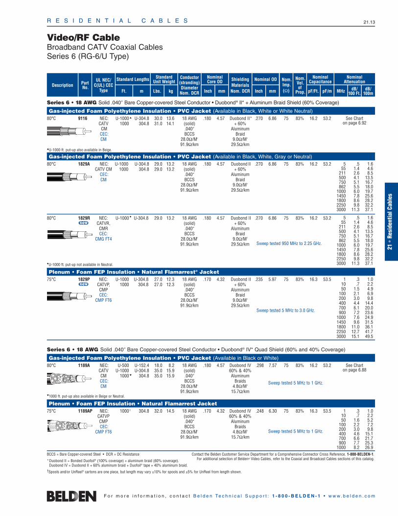
Series 6 • 18 AWG Solid .040″ Bare Copper-covered Steel Conductor • Duobond® II* + Aluminum Braid Shield (60% Coverage)
Gas-injected Foam Polyethylene Insulation • PVC Jacket (Available in Black, White or White Neutral)80°C 9116 NEC: U-1000 U-304.8 30.0 13.6 18 AWG .180 4.57 Duobond II* .270 6.86 75 83% 16.2 53.2
CATV 1000 304.8 31.0 14.1 (solid) + 60% CM .040″ Aluminum
CEC: BCCS BraidCM 28.0Ω/M′ 9.0Ω/M′
91.9Ω/km 29.5Ω/kmU-1000 ft. put-up also available in Beige.
Gas-injected Foam Polyethylene Insulation • PVC Jacket (Available in Black, White, Gray or Neutral)80°C 1829A NEC: U-1000 U-304.8 29.0 13.2 18 AWG .180 4.57 Duobond II .270 6.86 75 83% 16.2 53.2
CATV CM 1000 304.8 29.0 13.2 (solid) + 60% CEC: .040″ AluminumCM BCCS Braid
28.0Ω/M′ 9.0Ω/M′91.9Ω/km 29.5Ω/km
80°C 1829R NEC: U-1000 U-304.8 29.0 13.2 18 AWG .180 4.57 Duobond II .270 6.86 75 83% 16.2 53.2u CATVR, (solid) + 60%
CMR .040″ AluminumCEC: BCCS Braid
CMG FT4 28.0Ω/M′ 9.0Ω/M′91.9Ω/km 29.5Ω/km
U-1000 ft. put-up not available in Neutral.
Plenum • Foam FEP Insulation • Natural Flamarrest® Jacket75°C 1829P NEC: U-1000 U-304.8 27.0 12.3 18 AWG .170 4.32 Duobond II .235 5.97 75 83% 16.3 53.5
u CATVP, 1000 304.8 27.0 12.3 (solid) + 60%CMP .040″ AluminumCEC: BCCS Braid
CMP FT6 28.0Ω/M′ 9.0Ω/M′91.9Ω/km 29.5Ω/km
Series 6 • 18 AWG Solid .040″ Bare Copper-covered Steel Conductor • Duobond® IV* Quad Shield (60% and 40% Coverage)
Gas-injected Foam Polyethylene Insulation • PVC Jacket (Available in Black or White)80°C 1189A NEC: U-500 U-152.4 18.0 8.2 18 AWG .180 4.57 Duobond IV .298 7.57 75 83% 16.2 53.2
CATV U-1000 U-304.8 35.0 15.9 (solid) 60% & 40%CM 1000 304.8 35.0 15.9 .040″ AluminumCEC: BCCS BraidsCM 28.0Ω/M′ 4.8Ω/M′
91.9Ω/km 15.7Ω/km1000 ft. put-up also available in Beige or Neutral.
Plenum • Foam FEP Insulation • Natural Flamarrest Jacket75°C 1189AP NEC: 1000 † 304.8 32.0 14.5 18 AWG .170 4.32 Duobond IV .248 6.30 75 83% 16.3 53.5
CATVP (solid) 60% & 40%CMP .040″ AluminumCEC: BCCS Braids
CMP FT6 28.0Ω/M′ 4.8Ω/M′91.9Ω/km 15.7Ω/km
BCCS = Bare Copper-covered Steel • DCR = DC Resistance Contact the Belden Customer Service Department for a Comprehensive Connector Cross Reference. 1-800-BELDEN-1.
*Duobond II = Bonded Duofoil® (100% coverage) + aluminum braid (60% coverage). For additional selection of Belden® Video Cables, refer to the Coaxial and Broadcast Cables sections of this catalog.
Duobond IV = Duobond II + 60% aluminum braid + Duofoil® tape + 40% aluminum braid.†Spools and/or UnReel® cartons are one piece, but length may vary ±10% for spools and ±5% for UnReel from length shown.
R E S I D E N T I A L C A B L E S 21.13
21•
Resi
dent
ialC
able
s
F o r m o r e i n f o r m a t i o n , c o n t a c t B e l d e n Te c h n i c a l S u p p o r t : 1 - 8 0 0 - B E L D E N - 1 • w w w . b e l d e n . c o m
Video/RF CableBroadband CATV Coaxial CablesSeries 6 (RG-6/U Type)
ShieldingMaterialsNom. DCR
Nom.Imp.(Ω)
Nominal Core OD Nominal OD
Inch mm Inch mm
Conductor(stranding)DiameterNom. DCR
StandardUnit WeightStandard Lengths
Lbs. kgFt. m
UL NEC/C(UL) CEC
Type
PartNo.
MHz dB/100 Ft.
dB/100m
Nominal Attenuation
Nominal Capacitance
pF/mpF/Ft.
Nom.Vel.of
Prop.Description
1 .3 1.010 .7 2.250 1.6 5.2
100 2.2 7.2200 3.0 9.8400 4.6 15.1700 6.6 21.7900 7.7 25.3
1000 8.2 26.9
Sweep tested 5 MHz to 1 GHz.
See Chart on page 6.88
Sweep tested 5 MHz to 1 GHz.
5 .5 1.655 1.4 4.6
211 2.6 8.5500 4.1 13.5750 5.1 16.7862 5.5 18.0
1000 6.0 19.71450 7.8 25.61800 8.6 28.22250 9.8 32.23000 11.3 37.1
Sweep tested 5 MHz to 3.0 GHz.
1 .3 1.010 .7 2.250 1.5 4.9
100 2.1 6.9200 3.0 9.8400 4.4 14.4700 6.1 20.0900 7.2 23.6
1000 7.6 24.91450 9.6 31.51800 11.0 36.12250 12.7 41.73000 15.1 49.5
Sweep tested 950 MHz to 2.25 GHz.
5 .5 1.655 1.4 4.6
211 2.6 8.5500 4.1 13.5750 5.1 16.7862 5.5 18.0
1000 6.0 19.71450 7.8 25.61800 8.6 28.22250 9.8 32.23000 11.3 37.1
See Chart on page 6.92

RG-6/U Type • 18 AWG Solid .040″ Bare Copper Conductor • Duofoil® (100% Coverage) + Tinned Copper Braid Shield (95% Coverage)
Gas-injected Foam HDPE Insulation • PVC Jacket (Available in 10 colors)*SDI/HDTV 1694A NEC: 500 152.4 20.5 9.3 18 AWG .180 4.57 Duofoil .274 6.96 75 82% 16.2 53.2Digital Video CMR 1000 304.8 45.0 20.5 (solid) + 95%75°C CEC: 4500 1371.6 202.5 91.9 .040″ TC Braid
CMG FT4 BC 2.8Ω/M′6.4Ω/M′ 9.2Ω/km
21.0Ω/km
500 ft. put-up available in Black only.*Available in Black, Brown, Red, Orange, Yellow, Green, Blue, Purple, Gray or White.Black jacket suitable for Outdoor and Aerial applications.
Plenum • Foam FEP Teflon® Insulation • Flamarrest® Jacket (Available in 10 colors)**SDI/HDTV 1695A NEC: 500 † 152.4 20.5 9.3 18 AWG .170 4.32 Duofoil .234 5.94 75 82% 16.2 53.2Digital Video CMP 1000 † 304.8 45.0 20.5 (solid) + 95%75°C CEC: . 040″ TC Braid
CMP FT6 BC 2.8Ω/M′6.4Ω/M′ 9.2Ω/km
21.0Ω/km
500 ft. put-up available in Black or Natural only.**Available in Black, Brown, Red, Orange, Yellow, Green, Blue, Purple, Gray or Natural.Black jacket suitable for Outdoor and Aerial applications.
Gas-injected Foam HDPE Insulation • Overall Matte Black PVC Jacket (Color Code: See chart below)SDI/HDTV 7713A NEC: 500 152.4 463.0 210.0 18 AWG .180 4.57 Duofoil 1.386 35.20 75 82% 16.2 53.2Digital Video CMR 1000 304.8 904.0 410.4 (solid) Coax OD: + 95%75°C CEC: .040″ .275 6.99 TC Braid(1694A Bundled) CMG FT4 BC 3.0Ω/M′
6.4Ω/M′ 9.8Ω/km21.0Ω/km
RG-59/U Type • 20 AWG Solid .032″ Bare Copper Conductor • Duofoil (100% Coverage) + Tinned Copper Braid Shield (95% Coverage)
Gas-injected Foam HDPE Insulation • PVC Jacket (Available in 10 colors)
SDI/HDTV 1505A NEC: 500 152.4 15.5 7.0 20 AWG .145 3.68 Duofoil .233 5.92 75 83% 16.3 53.5Digital Video CMR 1000 304.8 35.0 15.9 (solid) + 95%75°C CEC: 5000 1524.0 165.0 74.9 .032″ TC Braid
CMG FT4 BC 3.8Ω/M′10.0Ω/M′ 12.5Ω/km32.8Ω/km
500 ft. put-up available in Black, Red or Blue only.1000 ft. and 5000 ft. put-ups available in all ten colors: Black, Brown, Red, Orange, Yellow, Green, Blue, Purple, Gray or White.
BC = Bare Copper • DCR = DC Resistance • HDPE = High-density Polyethylene • TC = Tinned Copper
Contact the Belden Customer Service Department for a Comprehensive Connector Cross Reference. 1-800-BELDEN-1. Request quotations of RG/U cables not listed.For additional selection of Belden® Video Cables, refer to the Coaxial and Broadcast Cables sections of this catalog.†Spools are one piece, but length may vary ±10% from length shown.
Teflon is a DuPont trademark.
R E S I D E N T I A L C A B L E S 21.14
F o r m o r e i n f o r m a t i o n , c o n t a c t B e l d e n Te c h n i c a l S u p p o r t : 1 - 8 0 0 - B E L D E N - 1 • w w w . b e l d e n . c o m
Video CablePrecision Video Cables for Analog and Digital ApplicationsRG-6/U and RG-59/U Types
ShieldingMaterialsNom. DCR
Nom.Imp.(Ω)
Nominal Core OD Nominal OD
Inch mm Inch mm
Conductor(stranding)DiameterNom. DCR
StandardUnit WeightStandard Lengths
Lbs. kgFt. m
UL NEC/C(UL) CEC
Type
PartNo.
MHz dB/100 Ft.
dB/100m
Nominal Attenuation
Nominal Capacitance
pF/mpF/Ft.
Nom.Vel.of
Prop.Description
1 .2 .83.6 .5 1.510 .7 2.4
71.5 1.6 5.2135 2.1 6.9270 3.0 9.7360 3.4 11.3540 4.3 13.9720 4.9 16.1750 5.0 16.4
1000 5.9 19.31500 7.3 24.02250 9.1 30.03000 10.7 35.04500 13.3 43.6
1 .2 .83.6 .5 1.510 .8 2.5
71.5 1.8 5.8135 2.4 7.9270 3.4 11.2360 4.0 13.1540 5.2 17.1720 6.1 20.0750 6.2 20.3
1000 7.3 24.01500 9.2 30.22250 11.6 38.03000 13.7 44.9
For Plenum version of 1694A, see 1695A.
Also available in bundled versions. See 7710A through 7713A.
100% Sweep tested. 5 MHz to 3 GHz.
100% Sweep tested. 5 MHz to 3 GHz.
1 .3 1.03.6 .6 1.810 .9 2.9
71.5 2.1 6.9135 2.7 8.9270 3.8 12.5360 4.4 14.4540 5.5 18.0720 6.4 21.0750 6.5 21.3
1000 7.6 24.91500 9.3 30.52250 11.6 38.03000 13.4 44.04500 16.4 53.8
For Plenum version of 1505A, see 1506A.
Also available in bundled versions. See 7794A through 7798A.
100% Sweep tested. 5 MHz to 3 GHz.
1 .2 .83.6 .5 1.510 .7 2.4
71.5 1.6 5.2135 2.1 6.9270 3.0 9.7360 3.4 11.3540 4.3 13.9720 4.9 16.1750 5.0 16.4
1000 5.9 19.31500 7.3 24.02500 9.1 31.83000 10.7 35.0
7713A has ten conductors.For other bundled versions of 1694A see 7710A through 7712A.
100% Sweep tested. 5 MHz to 3 GHz.
Color Code ChartCond. Color
1 Red2 Green3 Blue4 White5 Yellow
Cond. Color6 Brown7 Orange8 Gray9 Purple10 Black

R E S I D E N T I A L C A B L E S 21.15
21•
Resi
dent
ialC
able
s
F o r m o r e i n f o r m a t i o n , c o n t a c t B e l d e n Te c h n i c a l S u p p o r t : 1 - 8 0 0 - B E L D E N - 1 • w w w . b e l d e n . c o m
Subminiature RG-59/U Type • 23 AWG Solid .023″ Bare Copper Conductor • Duofoil® (100% Coverage) + TC Braid Shield (95% Coverage)
Gas-injected Foam HDPE Insulation • PVC Jacket (Available in 10 colors)*SDI/HDTV 1855A NEC: 500 152.4 9.0 4.1 23 AWG .102 2.59 Duofoil .159 4.03 75 82% 16.3 53.5Digital Video CMR 1000 304.8 16.0 7.3 (solid) + 95%75°C CEC: .023″ TC Braid
CMG FT4 BC 7.6Ω/M′20.1Ω/M′ 24.9Ω/km65.9Ω/km
500 ft. put-up available in Black only.
Standard Analog • RG-59/U Type • 23 AWG Solid .023″ Bare Copper Conductor • Bare Copper Braid Shield (95% Coverage)
Polyethylene Insulation • Black PVC JacketUL AWM 8241B NEC: U-1000 U-304.8 36.0 16.3 23 AWG .146 3.71 BC Braid .242 6.15 75 66% 20.5 67.3Style 1354 CM 1000 304.8 37.0 16.8 (solid) 95% Shield(30V 80°C) CEC: .023″ Coverage
CM BC 2.9Ω/M′20.4Ω/M′ 9.5Ω/km66.9Ω/km
Suitable for Outdoor applications.
BC = Bare Copper • DCR = DC Resistance • HDPE = High-density Polyethylene • TC = Tinned Copper
Contact the Belden Customer Service Department for a Comprehensive Connector Cross Reference. 1-800-BELDEN-1. Request quotations of RG/U cables not listed.For additional selection of Belden® Video Cables, refer to the Coaxial and Broadcast Cables sections of this catalog.
*Available in Brown, Red, Orange, Yellow, Green, Blue, Purple, Gray, White or Black.
Video CablePrecision Video Cables for Analog and Digital ApplicationsSubminiature and Standard Analog RG-59/U Types
ShieldingMaterialsNom. DCR
Nom.Imp.(Ω)
Nominal Core OD Nominal OD
Inch mm Inch mm
Conductor(stranding)DiameterNom. DCR
StandardUnit WeightStandard Lengths
Lbs. kgFt. m
UL NEC/C(UL) CEC
Type
PartNo.
MHz dB/100 Ft.
dB/100m
Nominal Attenuation
Nominal Capacitance
pF/mpF/Ft.
Nom.Vel.of
Prop.Description
1 .4 1.33.6 .8 2.610 1.2 3.9
71.5 3.1 10.0135 3.8 12.5270 5.4 17.7360 6.2 20.3540 7.7 25.3720 9.5 31.1750 9.6 31.5
1000 10.5 34.41500 13.0 42.62250 16.0 52.53000 18.5 60.74500 22.8 74.8
Also available in multiples, bundled. See 7787A through 7792A.
100% Sweep tested. 5 MHz to 3 GHz.
1 .4 1.310 1.1 3.650 2.4 7.9
100 3.4 11.2200 4.9 16.1400 7.0 23.0700 9.7 31.8900 11.1 36.4
1000 12.0 39.4

R E S I D E N T I A L C A B L E S 21.16
Video CableBundled RGB Precision Video Cable and Miniature Hi-Res Component Video Cables
F o r m o r e i n f o r m a t i o n , c o n t a c t B e l d e n Te c h n i c a l S u p p o r t : 1 - 8 0 0 - B E L D E N - 1 • w w w . b e l d e n . c o m
25 AWG Solid .018″ Tinned Copper Conductors • Duobond® + Tinned Copper Interlocked Serve Shield (95% Coverage)
FPFA Insulation • Inner PVC Jacket (Color Code: Red, Green, Blue, White, Yellow) • Overall Black PVC Jacket300V RMS 1277R NEC: 3 500 † 152.4 25.5 11.6 25 AWG .074 1.88 Duobond .320 8.13 75 80% 17.0 55.860°C u CMR 1000 † 304.8 48.0 21.8 (solid) Coax OD: + 95%
CEC: .018″ .114 2.90 TC BraidCMG TC 5.4Ω/M′
34.0Ω/M′ 17.7Ω/km111.6Ω/km
1278R NEC: 4 500 † 152.4 31.5 14.3 same .074 1.88 same .351 8.92u CMR 1000 † 304.8 60.0 27.2 as Coax OD: as
CEC: above .114 2.90 aboveCMG
1279R NEC: 5 250 † 76.2 21.8 9.9 same .074 1.88 same .403 10.24u CMR 500 † 152.4 40.5 18.4 as Coax OD: as
CEC: 1000 † 304.8 80.0 36.3 above .114 2.90 aboveCMG
1280R NEC: 6 500 † 152.4 44.0 20.0 same .074 1.88 same .423 10.74u CMR 1000 † 304.8 87.0 39.5 as Coax OD: as
CEC: above .114 2.90 aboveCMG
Miniature • 25 AWG Solid .018″ Tinned Copper Conductors • Duobond® (100% Coverage) + TC Braid Shield (95% Coverage)
Plenum • FPFA Insulation • Black Flamarrest® Jacket1282P NEC: 1 1000 304.8 10.0 4.5 25 AWG .074 1.88 Duobond .114 2.90 75 81% 17.0 55.2u CMP (solid) (100%)
CEC: .018″ TC + TC Braid CMP FT6 31.8Ω/M′ 5.8Ω/M′
104.3Ω/km 19.0Ω/km
BC = Bare Copper • DCR = DC Resistance • FPFA = Foam Perfluoroalkoxy • HDPE = High-density Polyethylene • TC = Tinned Copper
Contact the Belden Customer Service Department for a more Comprehensive Connector Cross Reference. 1-800-BELDEN-1. Request quotations of cables not listed.†Spools are one piece, but length may vary ±10% from length shown.
1 .5 1.75 1.2 3.8
50 3.7 12.1100 4.9 16.1200 6.7 22.0400 9.5 31.2750 13.4 44.0900 15.0 49.2
1000 15.8 51.83000 31.2 102.4
100% Sweep tested. 5 MHz to 850 MHz.
Conductor(stranding)DiameterNom. DCR
ShieldingMaterialsNom. DCR
No.of
Cond.
Nom.Imp.(Ω)
Nominal Core OD Nominal OD
Inch mm Inch mm
StandardUnit Weight
Standard Lengths
Lbs. kgFt. m
UL NEC/C(UL) CEC
Type MHz dB/100 Ft.
dB/100m
Nominal Attenuation
Nominal Capacitance
pF/mpF/Ft.
Nom.Vel.of
Prop.
PartNo. dB/
100m
Description
Sweep Tested 5 MHZ to 850 MHz.Guaranteed Return Loss -20dB Max.
1 .4 1.3 5 .9 3.0
50 3.7 12.1 100 5.0 16.4 200 7.0 23.0 400 10.0 32.8 700 14.5 47.6 900 17.0 55.8
1000 17.5 57.4 3000 37.0 121.4
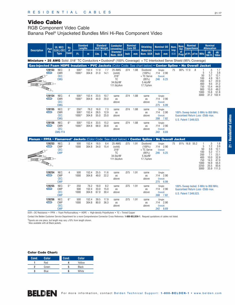
R E S I D E N T I A L C A B L E S 21.17
Video CableRGB Component Video CableBanana Peel® Unjacketed Bundles Mini Hi-Res Component Video
21•
Resi
dent
ialC
able
s
F o r m o r e i n f o r m a t i o n , c o n t a c t B e l d e n Te c h n i c a l S u p p o r t : 1 - 8 0 0 - B E L D E N - 1 • w w w . b e l d e n . c o m
Miniature • 25 AWG Solid .018″ TC Conductors • Duobond® (100% Coverage) + TC Interlocked Serve Shield (95% Coverage)
Gas-injected Foam HDPE Insulation • PVC Jackets (Color Code: See chart below) • Center Spline • No Overall Jacket1281S3 NEC: 3 500 † 152.4 17.0 7.7 25 AWG .074 1.88 Duobond Single: 75 80% 17.0 .8u CMR 1000 † 304.8 31.0 14.1 (solid) (100%) .114 2.90
CEC: .018″ + TC Serve Overall:CMG TC (95%) .246 6.25
34.0Ω/M′ 5.4Ω/M′111.6Ω/km 17.7Ω/km
1281S4 NEC: 4 500 † 152.4 23.5 10.7 same .074 1.88 same Single:u CMR 1000 † 304.8 44.0 20.0 as as .114 2.90
CEC: above above Overall:CMG .275 6.99
1281S5 NEC: 5* 250 † 76.2 16.0 7.3 same .074 1.88 same Single:u CMR 500 † 152.4 28.5 12.9 as as .114 2.90
CEC: 1000 † 304.8 55.0 25.0 above above Overall:CMG .308 7.82
1281S6 NEC: 6* 500 † 152.4 33.5 15.2 same .074 1.88 same Single:u CMR 1000 † 304.8 68.0 30.8 as as .114 2.90
CEC: above above Overall:CMG FT4 .342 8.69
Plenum • FPFA • Flamarrest® Jackets (Color Code: See chart below) • Center Spline • No Overall Jacket1282S3 NEC: 3 500 152.4 18.5 8.4 25 AWG .075 1.91 Duobond Single: 75 81% 16.8 55.2u CMP 1000 304.8 34.0 15.4 (solid) (100%) .114 2.90
CEC: .018″ + TC Serve Overall:CMP TC (95%) .246 6.25
34.0Ω/M′ 5.4Ω/M′111.6Ω/km 17.7Ω/km
1282S4 NEC: 4 500 152.4 25.5 11.6 same .075 1.91 same Single:u CMP 1000 304.8 49.0 22.2 as as .114 2.90
CEC: above above Overall:CMP .275 6.99
1282S5 NEC: 5* 250 76.2 18.0 8.2 same .075 1.91 same Single:u CMP 500 152.4 33.0 15.0 as as .114 2.90
CEC: 1000 304.8 67.0 30.4 above above Overall:CMP .308 7.82
1282S6 NEC: 6* 500 152.4 39.5 17.9 same .075 1.91 same Single:u CMP 1000 304.8 80.0 36.3 as as .114 2.90
CEC: above above Overall:CMP .342 8.69
DCR = DC Resistance • FPFA = Foam Perfluoroalkoxy • HDPE = High-density Polyethylene • TC = Tinned Copper
Contact the Belden Customer Service Department for a more Comprehensive Connector Cross Reference. 1-800-BELDEN-1. Request quotations of cables not listed.†Spools are one piece, but length may vary ±10% from length shown.*Also available with all Black jackets.
1 .5 1.7 5 1.2 3.8
50 3.7 12.1 100 4.9 16.1 200 6.7 22.0 400 9.5 31.2 750 13.4 44.0 900 15.0 49.2
1000 15.8 51.8 3000 31.2 102.4
1 .5 1.6 5 1.2 3.9
50 3.8 12.1 100 5.2 17.1 200 7.1 23.1 400 10.0 32.9 750 14.3 47.0
1000 16.9 55.4 2250 25.5 83.6 3000 33.9 111.3
100% Sweep tested. 5 MHz to 850 MHz.Guaranteed Return Loss -20db max.
U.S. Patent 7,049,523.
100% Sweep tested. 5 MHz to 850 MHz.Guaranteed Return Loss -20db max.
U.S. Patent 7,049,523.
Conductor(stranding)DiameterNom. DCR
ShieldingMaterialsNom. DCR
No.of
Cond.
Nom.Imp.(Ω)
Nominal Core OD Nominal OD
Inch mm Inch mm
StandardUnit Weight
Standard Lengths
Lbs. kgFt. m
UL NEC/C(UL) CEC
Type MHz dB/100 Ft.
dB/100m
Nominal Attenuation
Nominal Capacitance
pF/mpF/Ft.
Nom.Vel.of
Prop.
PartNo. dB/
100m
Description
Color Code Chart:
Cond. Color1 Red
2 Green
3 Blue
Cond. Color4 Yellow
5 Black
6 White

R E S I D E N T I A L C A B L E S 21.18
Video CableRGB Coaxial CableBanana Peel® Unjacketed VideoFLEX® Bundles, RG-59/U Type
F o r m o r e i n f o r m a t i o n , c o n t a c t B e l d e n Te c h n i c a l S u p p o r t : 1 - 8 0 0 - B E L D E N - 1 • w w w . b e l d e n . c o m
RG-59/U • 20 AWG Solid .032″ Bare Copper Conductors • Duofoil® (100% Coverage) + Tinned Copper Braid Shield (95% Coverage)
Plenum • Foam FEP Insulation • Plenum-Grade PVC Jackets (Color Code: See chart below) • Center Spline • No Overall Jacket300V RMS 1283S3 NEC: 3 250 76.2 26.3 11.9 20 AWG .133 3.38 Duofoil .422 10.72 75 83% 16.2 53.2
u CMP 500 152.4 54.0 24.5 (solid) (95%)CEC: 1000 304.8 103.0 46.7 .032″ + TC BraidCMP BC 3.8Ω/M′
10.0Ω/M′ 12.5Ω/km32.8Ω/km
1283S5 NEC: 5 250 76.2 43.5 19.7 same .133 3.38 same .529 13.44u CMP 500 152.4 88.0 39.9 as as
CEC: 1000 304.8 174.0 78.9 above aboveCMP
1283S6 NEC: 6 250 76.6 59.0 26.8 same .133 3.38 same .588 14.94u CMP 500 152.4 108.0 49.0 as as
CEC: 1000 304.8 209.0 94.8 above aboveCMP
Suitable for Indoor and Outdoor applications.
BC = Bare Copper • DCR = DC Resistance • FEP = Fluorinated Ethylene Propylene • TC = Tinned Copper
Contact the Belden Customer Service Department for a more Comprehensive Connector Cross Reference. 1-800-BELDEN-1. Request quotations of cables not listed.
1 .3 1.0 3.6 .6 2.0 10 .9 2.9
71.5 2.1 6.9135 2.7 8.9 270 3.8 12.5 360 4.4 14.4 540 5.5 18.0 720 6.4 21.0 750 6.5 21.3
1000 7.6 24.9 1500 9.4 30.8 2500 12.4 40.7 3000 13.8 45.3
Sweep tested. 5 MHz to 3 GHz.
U.S. Patent 7,049,523.
Conductor(stranding)DiameterNom. DCR
ShieldingMaterialsNom. DCR
No.of
Cond.
Nom.Imp.(Ω)
Nominal Core OD Nominal OD
Inch mm Inch mm
StandardUnit Weight
Standard Lengths
Lbs. kgFt. m
UL NEC/C(UL) CEC
Type MHz dB/100 Ft.
dB/100m
Nominal Attenuation
Nominal Capacitance
pF/mpF/Ft.
Nom.Vel.of
Prop.
PartNo. dB/
100m
Description
Color Code Chart:
Cond. Color1 Red
2 Green
3 Blue
Cond. Color4 Yellow
5 Black
6 White

R E S I D E N T I A L C A B L E S 21.19
Video CableHigh-Flex S-Video Cables
21•
Resi
dent
ialC
able
s
F o r m o r e i n f o r m a t i o n , c o n t a c t B e l d e n Te c h n i c a l S u p p o r t : 1 - 8 0 0 - B E L D E N - 1 • w w w . b e l d e n . c o m
High-Flex S-Video • 30 AWG Stranded (7x38) Tinned Copper Conductors • Tinned Copper Serve Shield (90% Coverage)
Foam HDPE Insulation • Matte Black PVC Jacket (One Coax Printed and Striped for Identification)Parallel Zip 1807A 2 U-500 U-152.4 8.0 3.6 30 AWG .056 1.42 TC Serve .110 2.79 75 78% 17.3 56.7Construction 500 152.4 7.5 3.4 (7x38) 90% Shield x x
U-1000 U-304.8 15.0 6.8 .012″ Coverage .230 5.841000 304.8 14.0 6.4 TC 7.5Ω/M′
100.0Ω/M′ 24.6Ω/km328.0Ω/km
Foam HDPE Insulation • Matte Black PVC Jacket (Inner PVC Jackets Color Code: Black and Yellow)Round 1808A 2 U-500 U-152.4 14.5 6.6 30 AWG .058 1.47 TC Serve .255 .84 75 78% 17.3 56.7Construction u 500 152.4 16.5 7.5 (7x38) Coax OD: 90% Shield
U-1000 U-304.8 31.0 14.1 .013″ .100 2.54 Coverage1000 304.8 33.0 15.0 TC 7.5Ω/M′
100.0Ω/M′ 24.6Ω/km328.0Ω/km
High-Flex S-Video • 30 AWG Stranded (7x38) .012″ Tinned Copper Conductors • Tinned Copper “French Braid” Shield (98% Coverage)
Plenum • Foam FEP Teflon® Insulation • Matte Black Flamarrest® Jacket (One Coax Printed and Striped for Identification)Parallel Zip 7700A NEC: 2 500 152.4 8.5 3.9 30 AWG .053 1.35 TC .107 2.72 75 78% 17.3 56.7Construction u CMP 1000 304.8 17.0 7.7 (7x38) “French x x
CEC: .012″ Braid” .214 5.44CMP FT6 TC 98% Shield
100.0Ω/M′ Coverage328.0Ω/km 7.5Ω/M′
24.6Ω/km
BC = Bare Copper • DCR = DC Resistance • FEP = Fluorinated Ethylene Propylene • HDPE = High-density Polyethylene • TC = Tinned Copper
Contact the Belden Customer Service Department for a Comprehensive Connector Cross Reference. 1-800-BELDEN-1. For additional selection of Belden® Video Cables, refer to the Coaxial and Broadcast Cables sections of this catalog.
For Plenum version of 1807A,see 7700A.
1 .6 2.05 1.4 4.6
10 2.1 6.930 3.8 12.550 5.1 16.7
100 7.6 24.9200 11.3 37.1400 16.9 55.4700 23.3 76.4900 26.9 88.2
1000 28.6 93.8
Available in Plenum versionsby special order only.
1 .6 2.05 1.4 4.6
10 2.1 6.930 3.8 12.550 5.1 16.7
100 7.6 24.9200 11.3 37.1400 16.9 55.4700 23.3 76.4900 26.9 88.2
1000 28.6 93.8
1 .5 2.35 1.7 5.6
10 2.3 7.530 4.1 13.450 5.3 17.4
100 7.6 24.9200 11.8 38.7400 17.6 57.7700 24.2 79.4900 28.0 91.8
1000 29.8 97.7
Conductor(stranding)DiameterNom. DCR
ShieldingMaterialsNom. DCR
No.of
Cond.
Nom.Imp.(Ω)
Nominal Core OD Nominal OD
Inch mm Inch mm
StandardUnit Weight
Standard Lengths
Lbs. kgFt. m
UL NEC/C(UL) CEC
Type MHz dB/100 Ft.
dB/100m
Nominal Attenuation
Nominal Capacitance
pF/mpF/Ft.
Nom.Vel.of
Prop.
PartNo. dB/
100m
Description
French Braid
Teflon is a DuPont trademark.

R E S I D E N T I A L C A B L E S 21.20
F o r m o r e i n f o r m a t i o n , c o n t a c t B e l d e n Te c h n i c a l S u p p o r t : 1 - 8 0 0 - B E L D E N - 1 • w w w . b e l d e n . c o m
Speaker CableLow-Capacitance OFHC Speaker Cable
Nominal Capacitance*
pF/Ft. pF/m
Low Cap • 16 AWG Stranded (65x34) Oxygen-free High-Conductivity Bare Copper Conductors • Conductors Cabled • Unshielded
Polyolefin Insulation • PVC Jacket (Available in Black, White, Gray, Blue or Green)1307A NEC: 2 U-500 U-152.4 15.0 6.8 .013 .32 .022 .56 .210 5.33 19.9 65.3u CMR, CL3R 1000 † 304.8 29.0 13.2
CEC:CMG FT4
Suitable for Direct Burial applications. White and Black jackets are Sunlight-resistant.
1308A NEC: 4 U-500 U-152.4 26.5 12.0 .013 .32 .026 .66 .270 6.86 19.9 65.3u CMR, CL3R 1000 † 304.8 54.0 24.5
CEC:CMG FT4
Suitable for Direct Burial applications. White and Black jackets are Sunlight-resistant.
Low Cap • 14 AWG Stranded (105x34) Oxygen-free High-Conductivity Bare Copper Conductors • Conductors Cabled • Unshielded
Polyolefin Insulation • PVC Jacket (Available in Black, White, Gray, Blue or Green)For Audio Use Only 1309A NEC: 2 U-500 U-152.4 22.5 10.2 .016 .39 .027 .69 .264 6.71 20.5 67.3
u CMR, CL3R 1000 † 304.8 46.0 20.9CEC:
CMG FT4
Suitable for Direct Burial applications. White and Black jackets are Sunlight-resistant.
For Audio Use Only 1310A NEC: 4 U-500 U-152.4 41.5 18.8 .016 .39 .033 .94 .319 8.10 20.5 67.3u CMR, CL3R 1000 † 304.8 84.0 38.1
CEC:CMG FT4
Suitable for Direct Burial applications. White and Black jackets are Sunlight-resistant.
Low Cap • 12 AWG Stranded (168x34) Oxygen-free High-Conductivity Bare Copper Conductors • Conductors Cabled • Unshielded
Polyolefin Insulation • PVC Jacket (Available in Black, White or Gray)For Audio Use Only 1311A NEC: 2 U-500 U-152.4 36.5 16.6 .018 .46 .036 .91 .352 8.94 22.3 73.2
u CMR, CL3R 500 152.4 36.5 16.6CEC: 1000 † 304.8 74.0 33.6
CMG FT4
Suitable for Direct Burial applications. White and Black jackets are Sunlight-resistant.
For Audio Use Only 1312A NEC: 4 500 152.4 66.5 30.2 .018 .46 .043 1.09 .423 10.74 22.3 73.2u CMR, CL3R 1000 † 304.8 132.0 59.9
CEC:CMG FT4
Suitable for Direct Burial applications. White and Black jackets are Sunlight-resistant.
Low Cap • 10 AWG Stranded (259x34) Oxygen-free High-Conductivity Bare Copper Conductors • Conductors Cabled
Polyolefin Insulation • PVC Jacket (Available in Black, White or Gray)For Audio Use Only 1313A NEC: 2 500 152.4 55.0 25.0 .019 .48 .044 1.12 .428 10.87 23.2 76.1
u CMR, CL3R 1000 † 304.8 109.0 49.5CEC:
CMG FT4
Suitable for Direct Burial applications. White and Black jackets are Sunlight-resistant.
OFHC = Oxygen-Free High-Conductivity
*Capacitance between conductors.†1000 ft. put-ups not available in Blue or Green.
UL NEC/C(UL) CEC
Type
PartNo.
No.of
Cond. Ft. m
Standard Lengths StandardUnit Weight
Lbs. kg
InsulationThickness
InchDescription
JacketThickness Nominal OD
Inch mmmm Inch mm
Color Code Chart
Cond. Color1 Black2 Red3 White4 Green
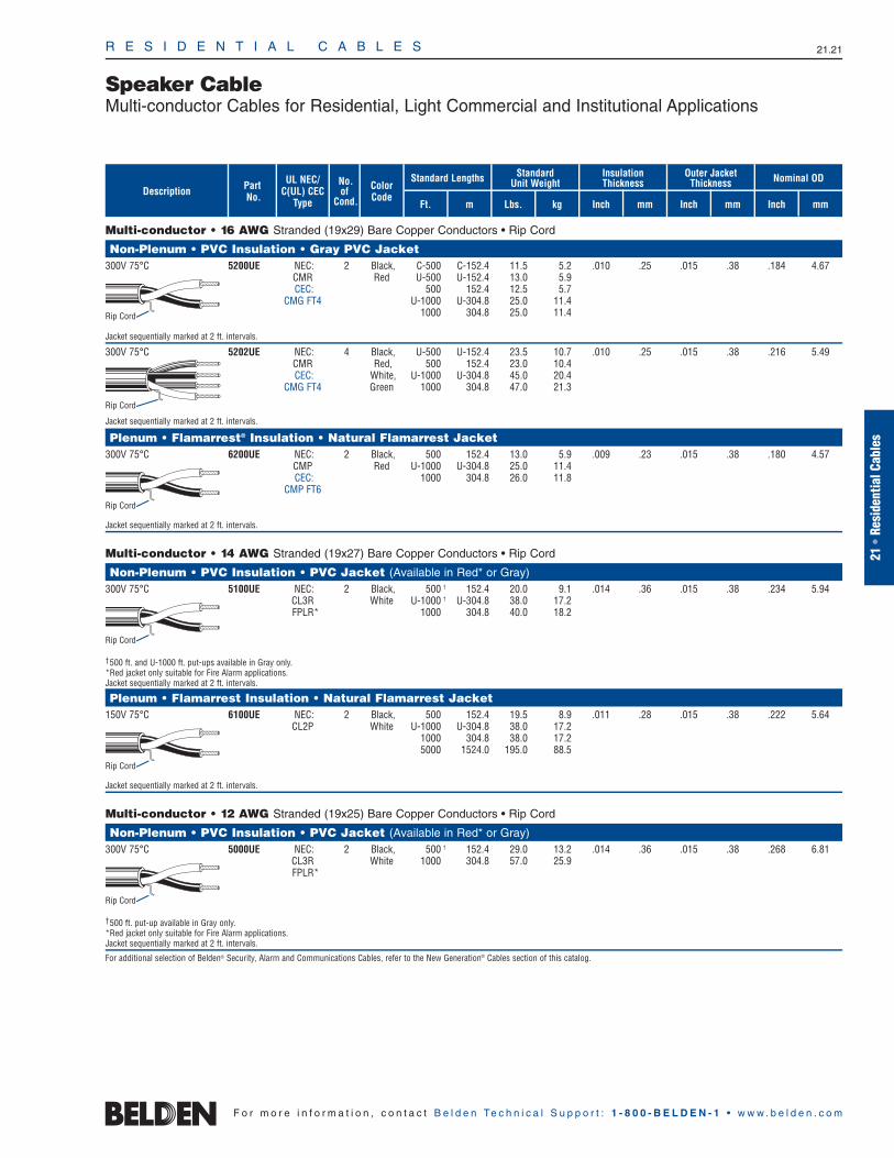
R E S I D E N T I A L C A B L E S 21.21
21•
Resi
dent
ialC
able
s
F o r m o r e i n f o r m a t i o n , c o n t a c t B e l d e n Te c h n i c a l S u p p o r t : 1 - 8 0 0 - B E L D E N - 1 • w w w . b e l d e n . c o m
Speaker CableMulti-conductor Cables for Residential, Light Commercial and Institutional Applications
Multi-conductor • 16 AWG Stranded (19x29) Bare Copper Conductors • Rip Cord
Non-Plenum • PVC Insulation • Gray PVC Jacket300V 75°C 5200UE NEC: 2 Black, C-500 C-152.4 11.5 5.2 .010 .25 .015 .38 .184 4.67
CMR Red U-500 U-152.4 13.0 5.9CEC: 500 152.4 12.5 5.7
CMG FT4 U-1000 U-304.8 25.0 11.41000 304.8 25.0 11.4
Jacket sequentially marked at 2 ft. intervals.
300V 75°C 5202UE NEC: 4 Black, U-500 U-152.4 23.5 10.7 .010 .25 .015 .38 .216 5.49CMR Red, 500 152.4 23.0 10.4CEC: White, U-1000 U-304.8 45.0 20.4
CMG FT4 Green 1000 304.8 47.0 21.3
Jacket sequentially marked at 2 ft. intervals.
Plenum • Flamarrest® Insulation • Natural Flamarrest Jacket300V 75°C 6200UE NEC: 2 Black, 500 152.4 13.0 5.9 .009 .23 .015 .38 .180 4.57
CMP Red U-1000 U-304.8 25.0 11.4CEC: 1000 304.8 26.0 11.8
CMP FT6
Jacket sequentially marked at 2 ft. intervals.
Multi-conductor • 14 AWG Stranded (19x27) Bare Copper Conductors • Rip Cord
Non-Plenum • PVC Insulation • PVC Jacket (Available in Red* or Gray)300V 75°C 5100UE NEC: 2 Black, 500 † 152.4 20.0 9.1 .014 .36 .015 .38 .234 5.94
CL3R White U-1000 † U-304.8 38.0 17.2FPLR* 1000 304.8 40.0 18.2
†500 ft. and U-1000 ft. put-ups available in Gray only.*Red jacket only suitable for Fire Alarm applications.Jacket sequentially marked at 2 ft. intervals.
Plenum • Flamarrest Insulation • Natural Flamarrest Jacket150V 75°C 6100UE NEC: 2 Black, 500 152.4 19.5 8.9 .011 .28 .015 .38 .222 5.64
CL2P White U-1000 U-304.8 38.0 17.21000 304.8 38.0 17.25000 1524.0 195.0 88.5
Jacket sequentially marked at 2 ft. intervals.
Multi-conductor • 12 AWG Stranded (19x25) Bare Copper Conductors • Rip Cord
Non-Plenum • PVC Insulation • PVC Jacket (Available in Red* or Gray)300V 75°C 5000UE NEC: 2 Black, 500 † 152.4 29.0 13.2 .014 .36 .015 .38 .268 6.81
CL3R White 1000 304.8 57.0 25.9FPLR*
†500 ft. put-up available in Gray only.*Red jacket only suitable for Fire Alarm applications.Jacket sequentially marked at 2 ft. intervals.
For additional selection of Belden® Security, Alarm and Communications Cables, refer to the New Generation® Cables section of this catalog.
UL NEC/C(UL) CEC
Type
ColorCode
Part No.
No.of
Cond. Ft. m
Standard Lengths Standard Unit Weight
Lbs. kg
Insulation Thickness
Inch mmDescription
Outer JacketThickness
Inch mm Inch mm
Nominal OD
Rip Cord
Rip Cord
Rip Cord
Rip Cord
Rip Cord
Rip Cord
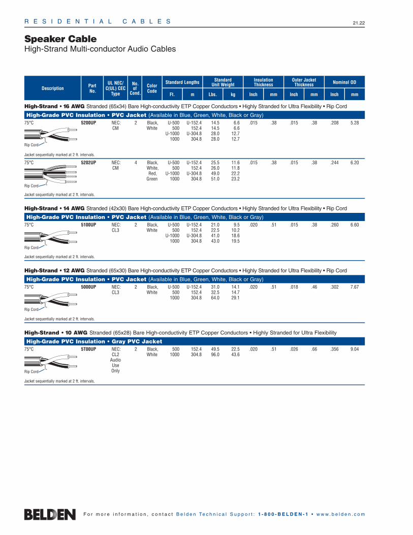
R E S I D E N T I A L C A B L E S 21.22
F o r m o r e i n f o r m a t i o n , c o n t a c t B e l d e n Te c h n i c a l S u p p o r t : 1 - 8 0 0 - B E L D E N - 1 • w w w . b e l d e n . c o m
Speaker CableHigh-Strand Multi-conductor Audio Cables
High-Strand • 16 AWG Stranded (65x34) Bare High-conductivity ETP Copper Conductors • Highly Stranded for Ultra Flexibility • Rip Cord
High-Grade PVC Insulation • PVC Jacket (Available in Blue, Green, White, Black or Gray)75°C 5200UP NEC: 2 Black, U-500 U-152.4 14.5 6.6 .015 .38 .015 .38 .208 5.28
CM White 500 152.4 14.5 6.6U-1000 U-304.8 28.0 12.7
1000 304.8 28.0 12.7
Jacket sequentially marked at 2 ft. intervals.
75°C 5202UP NEC: 4 Black, U-500 U-152.4 25.5 11.6 .015 .38 .015 .38 .244 6.20CM White, 500 152.4 26.0 11.8
Red, U-1000 U-304.8 49.0 22.2Green 1000 304.8 51.0 23.2
Jacket sequentially marked at 2 ft. intervals.
High-Strand • 14 AWG Stranded (42x30) Bare High-conductivity ETP Copper Conductors • Highly Stranded for Ultra Flexibility • Rip Cord
High-Grade PVC Insulation • PVC Jacket (Available in Blue, Green, White, Black or Gray)75°C 5100UP NEC: 2 Black, U-500 U-152.4 21.0 9.5 .020 .51 .015 .38 .260 6.60
CL3 White 500 152.4 22.5 10.2U-1000 U-304.8 41.0 18.6
1000 304.8 43.0 19.5
Jacket sequentially marked at 2 ft. intervals.
High-Strand • 12 AWG Stranded (65x30) Bare High-conductivity ETP Copper Conductors • Highly Stranded for Ultra Flexibility • Rip Cord
High-Grade PVC Insulation • PVC Jacket (Available in Blue, Green, White, Black or Gray)75°C 5000UP NEC: 2 Black, U-500 U-152.4 31.0 14.1 .020 .51 .018 .46 .302 7.67
CL3 White 500 152.4 32.5 14.71000 304.8 64.0 29.1
Jacket sequentially marked at 2 ft. intervals.
High-Strand • 10 AWG Stranded (65x28) Bare High-conductivity ETP Copper Conductors • Highly Stranded for Ultra Flexibility
High-Grade PVC Insulation • Gray PVC Jacket 75°C 5T00UP NEC: 2 Black, 500 152.4 49.5 22.5 .020 .51 .026 .66 .356 9.04
CL2 White 1000 304.8 96.0 43.6AudioUseOnly
Jacket sequentially marked at 2 ft. intervals.
UL NEC/C(UL) CEC
Type
ColorCode
Part No.
No.of
Cond. Ft. m
Standard Lengths Standard Unit Weight
Lbs. kg
Insulation Thickness
Inch mmDescription
Outer JacketThickness
Inch mm Inch mm
Nominal OD
Rip Cord
Rip Cord
Rip Cord
Rip Cord
Rip Cord

R E S I D E N T I A L C A B L E S 21.23
21•
Resi
dent
ialC
able
s
F o r m o r e i n f o r m a t i o n , c o n t a c t B e l d e n Te c h n i c a l S u p p o r t : 1 - 8 0 0 - B E L D E N - 1 • w w w . b e l d e n . c o m
Speaker CableHigh-Conductivity Electrolytic Tough Pitch (ETP) Copper Speaker Cables
16 AWG Stranded (26x30) ETP High-conductivity Copper Conductors • Parallel: (1) Tinned, (1) Bare
PVC Insulation • Clear PVC JacketParallel Zip Construction 9716 2 U-1000 U-304.8 27.0 12.3 .027 .69 .115 2.92300V 60°C 1000 304.8 26.0 11.8 x x
.230 5.84
14 AWG Stranded (19x27) ETP High-conductivity Copper Conductors • Parallel: (1) Tinned, (1) Bare
PVC Insulation • Clear PVC JacketParallel Zip Construction 9717 2 U-1000 U-304.8 42.0 19.1 .035 .89 .146 3.7160°C 1000 304.8 42.0 19.1 x x
.292 7.42
12 AWG Stranded (65x30) ETP High-conductivity Copper Conductors • Parallel: (1) Tinned, (1) Bare
PVC Insulation • Clear PVC JacketParallel Zip Construction 9718 2 500 152.4 33.0 15.0 .045 1.14 .185 4.7060°C 1000 304.8 66.0 30.0 x x
.370 9.40
UL NEC/C(UL) CEC
Type
Part No.
No.of
Cond. Ft. m
Standard Lengths Standard Unit Weight
Lbs. kg
Insulation Thickness
Inch mmDescription
Inch mm
Nominal OD
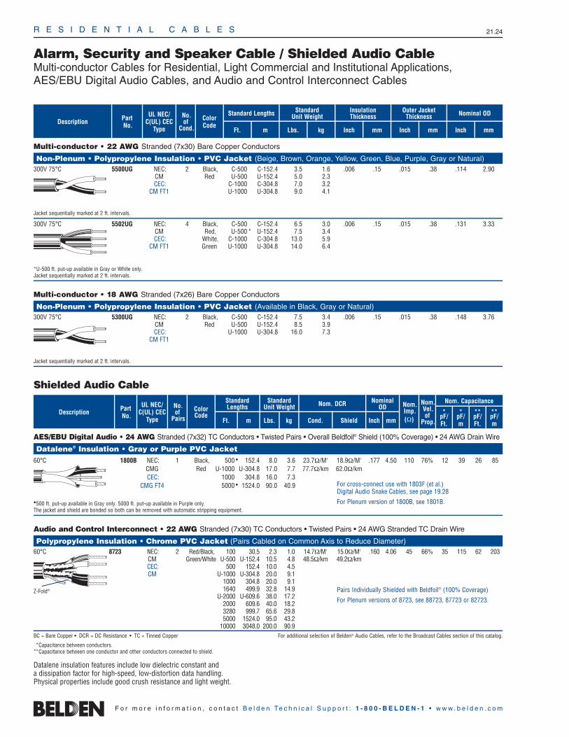
R E S I D E N T I A L C A B L E S 21.24
F o r m o r e i n f o r m a t i o n , c o n t a c t B e l d e n Te c h n i c a l S u p p o r t : 1 - 8 0 0 - B E L D E N - 1 • w w w . b e l d e n . c o m
Alarm, Security and Speaker Cable / Shielded Audio CableMulti-conductor Cables for Residential, Light Commercial and Institutional Applications,AES/EBU Digital Audio Cables, and Audio and Control Interconnect Cables
Multi-conductor • 22 AWG Stranded (7x30) Bare Copper Conductors
Non-Plenum • Polypropylene Insulation • PVC Jacket (Beige, Brown, Orange, Yellow, Green, Blue, Purple, Gray or Natural)300V 75°C 5500UG NEC: 2 Black, C-500 C-152.4 3.5 1.6 .006 .15 .015 .38 .114 2.90
CM Red U-500 U-152.4 5.0 2.3CEC: C-1000 C-304.8 7.0 3.2
CM FT1 U-1000 U-304.8 9.0 4.1
Jacket sequentially marked at 2 ft. intervals.
300V 75°C 5502UG NEC: 4 Black, C-500 C-152.4 6.5 3.0 .006 .15 .015 .38 .131 3.33CM Red, U-500 * U-152.4 7.5 3.4CEC: White, C-1000 C-304.8 13.0 5.9
CM FT1 Green U-1000 U-304.8 14.0 6.4
*U-500 ft. put-up available in Gray or White only.Jacket sequentially marked at 2 ft. intervals.
Multi-conductor • 18 AWG Stranded (7x26) Bare Copper Conductors
Non-Plenum • Polypropylene Insulation • PVC Jacket (Available in Black, Gray or Natural)300V 75°C 5300UG NEC: 2 Black, C-500 C-152.4 7.5 3.4 .006 .15 .015 .38 .148 3.76
CM Red U-500 U-152.4 8.5 3.9CEC: U-1000 U-304.8 16.0 7.3
CM FT1
Jacket sequentially marked at 2 ft. intervals.
UL NEC/C(UL) CEC
Type
ColorCode
Part No.
No.of
Cond. Ft. m
Standard Lengths Standard Unit Weight
Lbs. kg
Insulation Thickness
Inch mmDescription
Outer JacketThickness
Inch mm Inch mm
Nominal OD
AES/EBU Digital Audio • 24 AWG Stranded (7x32) TC Conductors • Twisted Pairs • Overall Beldfoil® Shield (100% Coverage) • 24 AWG Drain Wire
Datalene® Insulation • Gray or Purple PVC Jacket60°C 1800B NEC: 1 Black, 500 152.4 8.0 3.6 23.7Ω/M′ 18.9Ω/M′ .177 4.50 110 76% 12 39 26 85
CMG Red U-1000 U-304.8 17.0 7.7 77.7Ω/km 62.0Ω/kmCEC: 1000 304.8 16.0 7.3
CMG FT4 5000 1524.0 90.0 40.9
500 ft. put-up available in Gray only. 5000 ft. put-up available in Purple only.The jacket and shield are bonded so both can be removed with automatic stripping equipment.
Audio and Control Interconnect • 22 AWG Stranded (7x30) TC Conductors • Twisted Pairs • 24 AWG Stranded TC Drain Wire
Polypropylene Insulation • Chrome PVC Jacket (Pairs Cabled on Common Axis to Reduce Diameter)60°C 8723 NEC: 2 Red/Black, 100 30.5 2.3 1.0 14.7Ω/M′ 15.0Ω/M′ .160 4.06 45 66% 35 115 62 203
CM Green/White U-500 U-152.4 10.5 4.8 48.5Ω/km 49.2Ω/kmCEC: 500 152.4 10.0 4.5CM U-1000 U-304.8 20.0 9.1
1000 304.8 20.0 9.11640 499.9 32.8 14.9
U-2000 U-609.6 38.0 17.22000 609.6 40.0 18.23280 999.7 65.6 29.85000 1524.0 95.0 43.2
10000 3048.0 200.0 90.9BC = Bare Copper • DCR = DC Resistance • TC = Tinned Copper For additional selection of Belden® Audio Cables, refer to the Broadcast Cables section of this catalog.
*Capacitance between conductors.**Capacitance between one conductor and other conductors connected to shield.
Datalene insulation features include low dielectric constant and a dissipation factor for high-speed, low-distortion data handling. Physical properties include good crush resistance and light weight.
UL NEC/C(UL) CEC
Type
Part No.
No.of
Pairs Ft. m
Standard Lengths
StandardUnit Weight
Lbs. kg
Nom. DCR
Cond. ShieldDescription Color
Code
Nominal OD
Inch mm
Nom.Imp.(Ω)
Nom.Vel.of
Prop.
Nom. Capacitance
*pF/Ft.
*pF/m
**pF/Ft.
**pF/m
For cross-connect use with 1803F (et al.) Digital Audio Snake Cables, see page 19.28
For Plenum version of 1800B, see 1801B.
Z-Fold® Pairs Individually Shielded with Beldfoil® (100% Coverage)
For Plenum versions of 8723, see 88723, 87723 or 82723.
Shielded Audio Cable
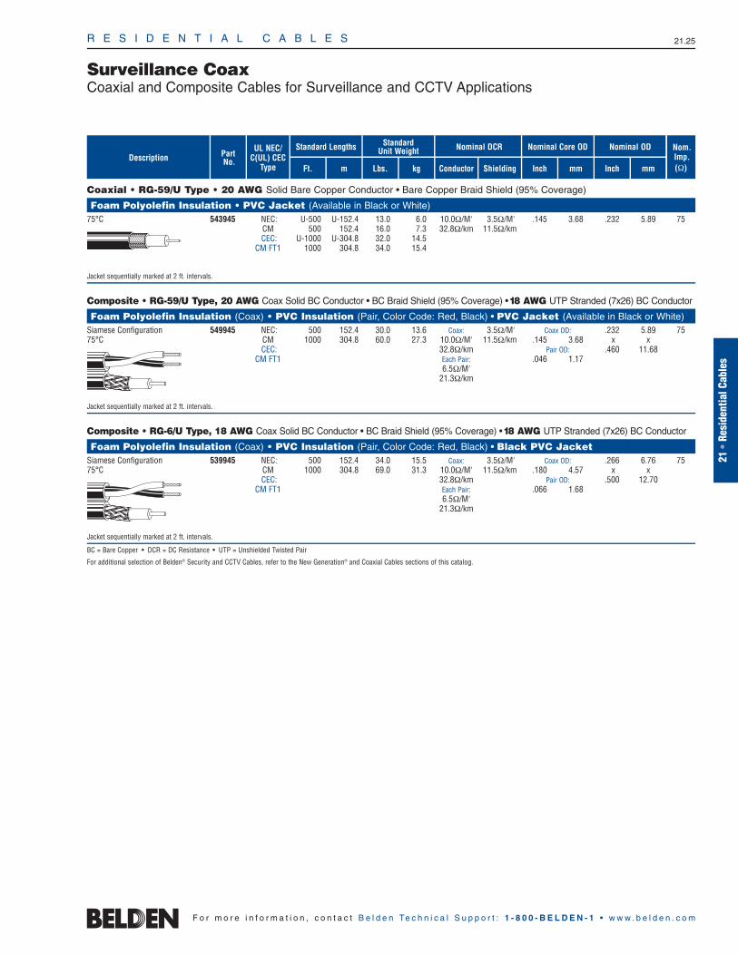
R E S I D E N T I A L C A B L E S 21.25
Surveillance CoaxCoaxial and Composite Cables for Surveillance and CCTV Applications
21•
Resi
dent
ialC
able
s
F o r m o r e i n f o r m a t i o n , c o n t a c t B e l d e n Te c h n i c a l S u p p o r t : 1 - 8 0 0 - B E L D E N - 1 • w w w . b e l d e n . c o m
Coaxial • RG-59/U Type • 20 AWG Solid Bare Copper Conductor • Bare Copper Braid Shield (95% Coverage)
Foam Polyolefin Insulation • PVC Jacket (Available in Black or White)75°C 543945 NEC: U-500 U-152.4 13.0 6.0 10.0Ω/M′ 3.5Ω/M′ .145 3.68 .232 5.89 75
CM 500 152.4 16.0 7.3 32.8Ω/km 11.5Ω/kmCEC: U-1000 U-304.8 32.0 14.5
CM FT1 1000 304.8 34.0 15.4
Jacket sequentially marked at 2 ft. intervals.
Composite • RG-59/U Type, 20 AWG Coax Solid BC Conductor • BC Braid Shield (95% Coverage) •18 AWG UTP Stranded (7x26) BC Conductor
Foam Polyolefin Insulation (Coax) • PVC Insulation (Pair, Color Code: Red, Black) • PVC Jacket (Available in Black or White)Siamese Configuration 549945 NEC: 500 152.4 30.0 13.6 Coax: 3.5Ω/M′ Coax OD: .232 5.89 7575°C CM 1000 304.8 60.0 27.3 10.0Ω/M′ 11.5Ω/km .145 3.68 x x
CEC: 32.8Ω/km Pair OD: .460 11.68CM FT1 Each Pair: .046 1.17
6.5Ω/M′21.3Ω/km
Jacket sequentially marked at 2 ft. intervals.
Composite • RG-6/U Type, 18 AWG Coax Solid BC Conductor • BC Braid Shield (95% Coverage) •18 AWG UTP Stranded (7x26) BC Conductor
Foam Polyolefin Insulation (Coax) • PVC Insulation (Pair, Color Code: Red, Black) • Black PVC Jacket Siamese Configuration 539945 NEC: 500 152.4 34.0 15.5 Coax: 3.5Ω/M′ Coax OD: .266 6.76 7575°C CM 1000 304.8 69.0 31.3 10.0Ω/M′ 11.5Ω/km .180 4.57 x x
CEC: 32.8Ω/km Pair OD: .500 12.70CM FT1 Each Pair: .066 1.68
6.5Ω/M′21.3Ω/km
Jacket sequentially marked at 2 ft. intervals.
BC = Bare Copper • DCR = DC Resistance • UTP = Unshielded Twisted Pair
For additional selection of Belden® Security and CCTV Cables, refer to the New Generation® and Coaxial Cables sections of this catalog.
Nom.Imp.(Ω)
Nominal Core OD Nominal OD
Inch mm Inch mmShielding
Nominal DCR
Conductor
StandardUnit WeightStandard Lengths
Lbs. kgFt. m
UL NEC/C(UL) CEC
Type
PartNo.Description

R E S I D E N T I A L C A B L E S 21.26
Tools and AccessoriesCompression and Cable Prep ToolsOne-piece, Male Connectors for Mini Hi-Res Coaxial Cable
F o r m o r e i n f o r m a t i o n , c o n t a c t B e l d e n Te c h n i c a l S u p p o r t : 1 - 8 0 0 - B E L D E N - 1 • w w w . b e l d e n . c o m
SpecificationsImpedance 75ΩFrequency Range DC–3.0 GHz (dependent upon Cable limitations)
Insertion Loss <.1 dB @ 1 GHzReturn Loss >20 dB; 5–1000 MHzCable Retention Force >40 lbs.Center Conductor Contact Plating >.0003″ Gold on Beryllium CopperCenter Pin Retention >150 gramsMating Style 2-stud Bayonet LockCurrent Rating 5 ampMax. Working Voltage 300 VrmsBody Material BrassBody Plating Nickel or GoldRFI >100 dBCable Attachment Method Compression Style; 1-piece
75-Ohm BNC Connectors
Product Description
One-piece male connector for 25 AWG Mini Hi-Res Coaxial cable. Compressionattachment method for contact and body.Use Belden HCCT Compression Tool.
Belden Part No. 1B25A (Nickel-plated Body)HC2920A (Gold-plated Body)
SpecificationsImpedance For 75Ω cables (75Ω style)Cable Retention Force >40 lbs.Center Pin Plating Gold on Beryllium CopperCenter Pin Retention >150 gramsMating Style RCA Standard InterfaceCurrent Rating 2 ampsMax. Working Voltage 300 VrmsBody Material BrassBody Plating Nickel or GoldCable Attachment Method Compression Style; 1-piece
HCST Cable Prep Tool
Product Description
Cable stripping tool for use with RG-6, RG-59, Mini RG-59 and RGB Coaxial cable.Belden Part No. HCST 000001
HCCT Compression Tool
Product Description
Suitable for use with BNC, RCA and FConnectors including Belden 1B25A, 1R25A,HC2920A and HC22910A connectors.Belden Part No. HCCT 000020
Compatible Cables
25 AWG Solid Center ConductorMiniature Hi-Res RGB Coax Cables
CMR CMP1 Coax 1281R 1282P
Banana Peel® Spline Constructions3 Coax RGB 1281S3 1282S34 Coax RGBS 1281S4 1282S45 Coax RGBHV 1281S5 1282S56 Mini Coaxes 1281S6 1282S6
Jacketed Constructions3 Coax RGB 1277R 1277P4 Coax RGBS 1278R 1278P5 Coax RGBHV 1279R 1279P6 Mini Coaxes 1280R 1280P
RCA Connectors
Product Description
One-piece male connector for 25 AWG Mini Hi-Res Coaxial cable. Compressionattachment method for contact and body.Use Belden HCCT Compression Tool.
Belden Part No. 1R25A (Nickel-plated Body)HC2910A (Gold-plated Body)
22
Table of ContentsTechnical Information Page No.
Conductors 22.2–22.5Table 1: Solid Copper Wire, American Wire Gage 22.2Table 2: Stranded Copper Wire, American Wire Gage 22.3Table 3: Current Ratings for Belden® Electronic Cables 22.4Table 4: Metric/Imperial/Circular Mills/AWG Equivalents 22.5
Insulations and Jackets 22.6–22.11Insulations: Overview 22.6Jackets: Overview 22.6Characteristics of Popular Insulation and Jacket Compounds 22.7Table 4: Comparative Properties of Plastic Compounds 22.8Table 5: Comparative Properties of Fluoropolymers 22.9Table 6: Comparative Properties of Rubber Insulations 22.10Table 7: Nominal Temperature Ranges 22.11
Shielding and Armoring 22.12–22.14Shielding: Overview 22.12Characteristics of Belden Shield Types 22.13
Foil Shields 22.13Braid Shields 22.13Spiral/Serve Shields 22.13“French Braid” Shields 22.13Combination Shields 22.13
Shield Types: Application Guide 22.14Table 8: Relative Cost Comparison of Shield Types 22.14Table 9: Shield Performance Comparison 22.14Armoring: Overview 22.14
Metric Conversions 22.15–22.16Table 10: Temperature Conversions 22.15Table 11: Distance and Weight Conversion Formulas 22.15Table 12: Conductor Size Equivalents 22.16
Belden Color Code Charts 22.17–22.19Cable Standards Reference Guide 22.20
National Electrical Code (NEC) 22.20Impact of NEC 22.20Intended Uses of Appliance Wiring Materials (AWM) 22.20
C(UL) Certifications 22.20FT1 Vertical Flame Test 22.20FT4 Vertical Flame Test — Cables in Trays 22.20FT6 Horizontal Flame and Smoke Test 22.20
NEC Cable Substitution Chart 22.21Canadian Electrical Code (CEC) Substitution Chart 22.22Terms of Use of Master Catalog 22.22Environmental Regulations and Compliance 22.23Cable Packaging 22.24
UnReel® 22.24Reel-in-a-Box 22.24
Glossary 22.25–22.36
The information, graphs, tables and illustrations presented in this section are provided to assist Belden customers with the selection of the most appropriate cable for their application. For further assistance, contact Belden Technical Support at: 1-800-BELDEN-1.
Tech
nic
al In
form
atio
n
22.1

T E C H N I C A L I N F O R M A T I O N 22.2
ConductorsTable 1: Solid Copper Wire, American Wire Gage
F o r m o r e i n f o r m a t i o n , c o n t a c t B e l d e n Te c h n i c a l S u p p o r t : 1 - 8 0 0 - B E L D E N - 1 • w w w . b e l d e n . c o m
Unparalleled Performance
Belden is one of only a very few cable manufacturers to draw and anneal its own conductors. This is a time-consumingprocess, but it allows us to ensure signalintegrity, as well as proper physical characteristics.
In addition, the standards under which wedesign and manufacture our fiber opticcabling are among the strictest in theindustry. The result is a comprehensiveoffering of products which give unparalleled performance and can satisfy your most demanding operating and environmental challenges.
10 .1019 2.60 10380.0 31.43 .998911 .0907 2.30 8234.0 24.92 1.26012 .0808 2.05 6530.0 19.77 1.58813 .0720 1.83 5178.0 15.68 2.00314 .0641 1.63 4107.0 12.43 2.52515 .0571 1.45 3260.0 9.858 3.18416 .0508 1.29 2583.0 7.818 4.01617 .0453 1.15 2050.0 6.200 5.06418 .0403 1.02 1620.0 4.917 6.38519 .0359 .912 1200.0 3.899 8.05120 .0320 .813 1020.0 3.092 10.1521 .0285 .724 812.1 2.452 12.8022 .0253 .643 640.4 1.945 16.1423 .0226 .574 511.5 1.542 20.3624 .0201 .511 404.0 1.223 25.6725 .0179 .455 320.4 .9699 32.3726 .0159 .404 253.0 .7692 40.8127 .0142 .361 201.5 .6100 51.4728 .0126 .320 159.8 .4837 64.9029 .0113 .287 126.7 .3836 81.8330 .0100 .254 100.5 .3042 103.231 .0089 .226 79.7 .2413 130.132 .0080 .203 63.21 .1913 164.133 .0071 .180 50.13 .1517 206.934 .0063 .160 39.75 .1203 260.935 .0056 .142 31.52 .09542 331.036 .0050 .127 25.00 .07568 414.837 .0045 .114 19.83 .0613 512.138 .0040 .102 15.72 .04759 648.639 .0035 .089 12.20 .03774 847.840 .0031 .079 9.61 .02993 1080.0
Information from National Bureau of Standards Copper Wire Tables — Handbook 100.
Inches mm
Gage (AWG)
Nominal ODNominal
Circular MIL AreaNominal Weight
(Lbs. per 1000 Ft.)
Nominal Resistance @ 68°F
(Ω/1000 Ft.)
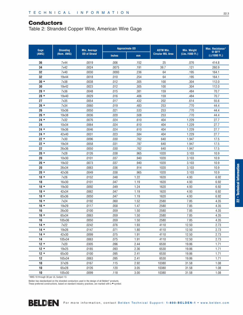
T E C H N I C A L I N F O R M A T I O N 22.3
ConductorsTable 2: Stranded Copper Wire, American Wire Gage
22 •
Tech
nica
l Inf
orm
atio
n
F o r m o r e i n f o r m a t i o n , c o n t a c t B e l d e n Te c h n i c a l S u p p o r t : 1 - 8 0 0 - B E L D E N - 1 • w w w . b e l d e n . c o m
36 7x44 .0019 .006 .152 25 .076 414.834 7x42 .0024 .0075 .191 39.7 .121 260.932 7x40 .0030 .0093 .236 64 .195 164.132 19x44 .0018 .010 .254 64 .195 164.130 7x38 .0038 .012 .305 100 .304 112.030 19x42 .0023 .012 .305 100 .304 112.028 7x36 .0048 .015 .381 159 .484 70.728 19x40 .0029 .016 .406 159 .484 70.727 7x35 .0054 .017 .432 202 .614 55.626 7x34 .0060 .019 .483 253 .770 44.426 10x36 .0050 .021 .533 253 .770 44.426 19x38 .0036 .020 .508 253 .770 44.424 7x32 .0076 .024 .610 404 1.229 27.724 10x34 .0064 .024 .610 404 1.229 27.724 19x36 .0046 .024 .610 404 1.229 27.724 42x40 .0031 .023 .584 404 1.229 27.722 7x30 .0096 .030 .762 640 1.947 17.522 19x34 .0058 .031 .787 640 1.947 17.522 26x36 .0050 .030 .762 640 1.947 17.520 7x28 .0126 .038 .965 1020 3.103 10.920 10x30 .0101 .037 .940 1020 3.103 10.920 19x32 .0073 .037 .940 1020 3.103 10.920 26x34 .0063 .036 .914 1020 3.103 10.920 42x36 .0049 .038 .965 1020 3.103 10.918 7x26 .0152 .048 1.22 1620 4.93 6.9218 16x30 .0101 .047 1.19 1620 4.93 6.9218 19x30 .0092 .049 1.24 1620 4.93 6.9218 42x34 .0062 .047 1.19 1620 4.93 6.9218 65x36 .0050 .047 1.19 1620 4.93 6.9216 7x24 .0192 .060 1.52 2580 7.85 4.3516 19x29 .0117 .058 1.47 2580 7.85 4.3516 26x30 .0100 .059 1.50 2580 7.85 4.3516 65x34 .0063 .059 1.50 2580 7.85 4.3516 105x36 .0050 .059 1.50 2580 7.85 4.3514 7x22 .0242 .076 1.93 4110 12.50 2.7314 19x26 .0147 .071 1.80 4110 12.50 2.7314 42x30 .0099 .075 1.91 4110 12.50 2.7314 105x34 .0063 .075 1.91 4110 12.50 2.7312 7x20 .0305 .096 2.44 6530 19.86 1.7112 19x25 .0185 .093 2.36 6530 19.86 1.7112 65x30 .0100 .095 2.41 6530 19.86 1.7112 165x34 .0063 .095 2.41 6530 19.86 1.7110 37x26 .0167 .115 2.92 10380 31.58 1.0810 65x28 .0126 .120 3.05 10380 31.58 1.0810 105x30 .0099 .118 3.00 10380 31.58 1.08
*AWG 10 through 30 per UL Subject 13.
Belden has standardized on the stranded conductors used in the design of all Belden® products. These preferred constructions, based on standard industry practices, are marked with a symbol.
Stranding(Nom. AWG)
Min. Average OD of Strand
ASTM Min.Circular MIL Area
Min. Weight(Lbs./1000 Ft.)
Max. Resistance* @ 68°F
(Ω/1000 Ft.)
Gage (AWG)
Inches mm
Approximate OD
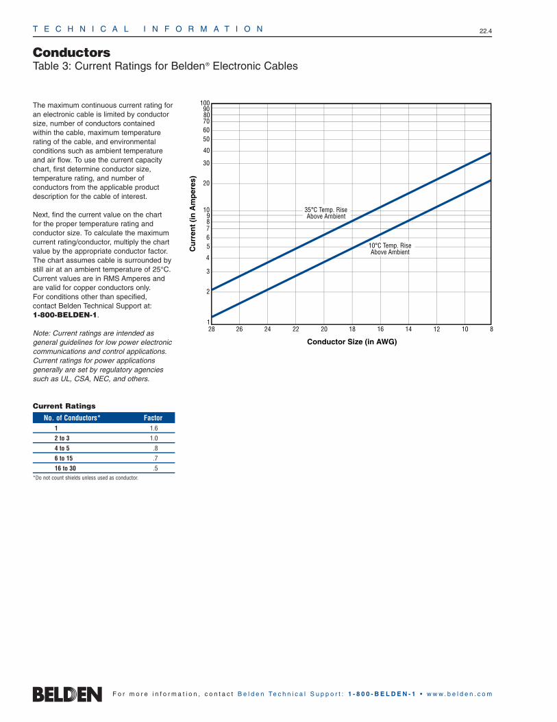
T E C H N I C A L I N F O R M A T I O N 22.4
F o r m o r e i n f o r m a t i o n , c o n t a c t B e l d e n Te c h n i c a l S u p p o r t : 1 - 8 0 0 - B E L D E N - 1 • w w w . b e l d e n . c o m
ConductorsTable 3: Current Ratings for Belden® Electronic Cables
The maximum continuous current rating foran electronic cable is limited by conductorsize, number of conductors contained within the cable, maximum temperature rating of the cable, and environmental conditions such as ambient temperatureand air flow. To use the current capacitychart, first determine conductor size, temperature rating, and number of conductors from the applicable productdescription for the cable of interest.
Next, find the current value on the chart for the proper temperature rating and conductor size. To calculate the maximumcurrent rating/conductor, multiply the chartvalue by the appropriate conductor factor.The chart assumes cable is surrounded bystill air at an ambient temperature of 25°C.Current values are in RMS Amperes andare valid for copper conductors only. For conditions other than specified, contact Belden Technical Support at: 1-800-BELDEN-1.
Note: Current ratings are intended as general guidelines for low power electroniccommunications and control applications.Current ratings for power applications generally are set by regulatory agenciessuch as UL, CSA, NEC, and others.
Conductor Size (in AWG)
24 222628 18 16 14 12 10 8201
2
3
4
56789
10
20
30
40
5060708090
100
Cu
rren
t (i
n A
mp
eres
)
10°C Temp. RiseAbove Ambient
35°C Temp. RiseAbove Ambient
Current Ratings
No. of Conductors* Factor1 1.6
2 to 3 1.0
4 to 5 .8
6 to 15 .7
16 to 30 .5*Do not count shields unless used as conductor.
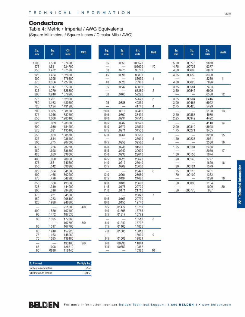
Sq.mm
Sq.in.
Cir.mils
AWG
T E C H N I C A L I N F O R M A T I O N 22.5
22 •
Tech
nica
l Inf
orm
atio
n
F o r m o r e i n f o r m a t i o n , c o n t a c t B e l d e n Te c h n i c a l S u p p o r t : 1 - 8 0 0 - B E L D E N - 1 • w w w . b e l d e n . c o m
ConductorsTable 4: Metric / Imperial / AWG Equivalents (Square Millimeters / Square Inches / Circular Mils / AWG)
1000 1.550 1974000975 1.511 1924700950 1.472 1875300925 1.434 1826000900 1.395 1776600875 1.356 1727300850 1.317 1677900825 1.279 1628600800 1.240 1579200775 1.201 1529900750 1.163 1480500725 1.124 1431200700 1.085 1381800675 1.046 1332500650 1.008 1283100625 .969 1233800600 .930 1184400575 .891 1135100550 .853 1085700525 .814 1036400500 .775 987000475 .736 937700450 .698 888300425 .659 839000400 .620 789600375 .581 740300350 .542 690900325 .504 641600300 .465 592200275 .426 542900250 .388 493500225 .349 444200200 .310 394800175 .271 345500150 .233 296100125 .1938 246800— — 211600 4/0
100 .1550 19740095 .1472 18753090 .1395 177660— — 167800 3/085 .1317 16779080 .1240 15792075 .1163 14805070 .1085 138180— — 133100 2/065 .1008 12831060 .0930 118440
Sq.mm
Sq.in.
Cir.mils
AWG
55 .0853 108570— — 105600 1/050 .0775 9870045 .0698 88830— — 83690 140 .0620 7896035 .0542 69090— — 66360 230 .0465 59220— — 52620 325 .0388 49350— — 41740 4
20.0 .0310 3948019.5 .0302 3849019.0 .0294 3751018.5 .0287 3652018.0 .0279 3553017.5 .0271 3455017.0 .0264 33560
— — 33090 516.5 .0256 3256016.0 .0248 3158015.5 .0240 3060015.0 .0233 2961014.5 .0225 2862014.0 .0217 2764013.5 .0209 26650
— — 26420 613.0 .0201 2566012.5 .0194 2468012.0 .0186 2369011.5 .0178 2270011.0 .0171 21710
— — 20820 710.5 .0163 2073010.0 .0155 197409.5 .01472 187539.0 .01395 177668.5 .01317 16779— — 16510 88.0 .01240 157927.5 .01163 148057.0 .01085 13818— — 13090 96.5 .01008 128316.0 .00930 118445.5 .00853 10857— — 10380 10
Sq.mm
Sq.in.
Cir.mils
AWG
5.00 .00775 98704.75 .00736 93774.50 .00698 88834.25 .00659 8390
— — 8230 114.00 .00620 78963.75 .00581 74033.50 .00542 6909
— — 6530 123.25 .00504 64163.00 .00465 59222.75 .00426 5429
— — 5180 132.50 .00388 49352.25 .00349 4422
— — 4110 142.00 .00310 39481.75 .00271 3455
— — 3260 151.50 .00233 2961
— — 2580 161.25 .00194 2468
— — 2050 171.00 .00155 1974.90 .00140 1777— — 1620 18.80 .00124 1579.75 .00116 1481.70 .00109 1382— — 1290 19.60 .00093 1184— — 1029 20.50 .000775 987
To Convert: Multiply by:
Inches to millimeters 25.4
Millimeters to inches .03937

Insulations and JacketsOverview
T E C H N I C A L I N F O R M A T I O N 22.6
F o r m o r e i n f o r m a t i o n , c o n t a c t B e l d e n Te c h n i c a l S u p p o r t : 1 - 8 0 0 - B E L D E N - 1 • w w w . b e l d e n . c o m
Insulations
Belden expends a great amount of timeand effort to formulate its own insulations.As a result, Belden® insulations providesuperior performance under a variety ofhostile environmental conditions. Beldencables are available in UL Listed and CSA Approved insulation compounds.
Among the insulations we utilize are:
Polyethylene
Polyvinyl-chloride (PVC)
Polypropylene
Also available are:
Datalene® — For computer and data transmission. Datalene is crushresistant, lightweight, and offers goodperformance characteristics over a wide range of temperatures.
Teflon® Insulated Plenum & High-Temperature Cables — For data communications, instrumentation/control, and other commercial and industrial applications.Plenum cables eliminate the need forconduit and reduce installation time.
Jackets
Belden electronic cables are manufacturedin a wide selection of jacketing materials.
Flamarrest® — A Belden jacketinginnovation, Flamarrest is a low-smoke,flame retardant compound that is fivetimes more flexible than fluorocopolymer.Cables jacketed with Flamarrest are cost efficient and easy to install.
Also included in our wide selection of jacketing compounds are:
Polyvinyl-chloride
Polyethylene
Polyurethane
Teflon
Tefzel®
Halar®
Neoprene
EPDM
Hypalon®
Silicone rubber
Natural rubber
Special compounds and variations of standard compounds are used as well.
Teflon, Tefzel and Hypalon are DuPont trademarks.Halar is an Ausimont Corporation trademark.

T E C H N I C A L I N F O R M A T I O N 22.7
22 •
Tech
nica
l Inf
orm
atio
n
F o r m o r e i n f o r m a t i o n , c o n t a c t B e l d e n Te c h n i c a l S u p p o r t : 1 - 8 0 0 - B E L D E N - 1 • w w w . b e l d e n . c o m
Insulations and JacketsTypical Characteristics of Popular Insulation and Jacketing Compounds
EPDM
EPDM (ethylene-propylene-diene elastomer)is a chemically cross-linked elastomer withexcellent flexibility at high and low tempera-tures (150° to -55°C). It has good insulationresistance and dielectric strength, as well asexcellent abrasion resistance and mechanicalproperties. EPDM also has better cut-throughresistance than Silicone rubber, which itreplaces in some applications.
EPDM is compatible with most varnishes, butafter the dip and bake cycle varnish tends toadhere to the insulation (because EPDM,unlike some rubber insulations, does notexude oils or waxes). As lead wires arepulled apart for termination, the varnishcracks, sometimes breaking the insulation.
To resolve this problem, a stearic solutionis applied to the lead wire during the put-upprocess. This ensures that rigid varnishdoes not cause EPDM insulation to rupturewhen the wire is terminated.
Field evaluations by numerous users revealthat the coated EPDM has excellent varnishresistance at least equal to synthetic elas-tomers, cross-link polyethylene, or Siliconeglass braid in dip and bake systems.
Flamarrest®
Flamarrest is a plenum grade chloride-based jacketing material with low smokeand low flame spread properties. Cablesjacketed with Flamarrest meet the ANSI/NFPA Standard 262-1985 (UL910), Plenum Cable Flame Test.
Halar®
Thermoplastic fluoropolymer material withexcellent chemical resistance, electricalproperties, thermal characteristics, and impact resistance. The temperature ratingis -70°C to 150°C.
Neoprene
The temperature range of this material canvary from -55°C to 90°C. The actual rangewould depend on the formulation used.Neoprene is both oil-resistant and sunlight-resistant, making it ideal for many outdoorapplications. The most stable colors areBlack, Dark Brown, and Gray. The electricalproperties are not as good as other insulationmaterials. Because of this, thicker insulationshould be used. Typical designs where thismaterial is used are lead wire insulationand cable jackets.
Polyethylene (Solid and Foamed)
A very good insulation in terms of electricalproperties. Low dielectric constant, a stabledielectric constant over all frequencies,very high insulation resistance. In terms offlexibility, polyethylene can be rated stiff tovery hard, depending on molecular weightand density—low density being the mostflexible, with high-density, high-molecularweight formulation being very hard. Moistureresistance is rated excellent. Black andspecially formulated colored versions haveexcellent weather resistance. The dielectricconstant is 2.3 for solid insulation and typically 1.64 for foam designs. Flameretardant formulations are available withdielectric constants ranging from about 1.7 for foam flame retardant to 2.58 forsolid flame retardant polyethylene.
Polypropylene (Solid and Foam)
Similar in electrical properties to poly-ethylene. This material is primarily used asan insulation material. Typically, it is harderthan polyethylene. This makes it suitablefor thin wall insulations. UL maximum temperature rating may be 60°C, 80°C or105°C. The dielectric constant is 2.25 forsolid and typically 1.55 for foam designs.
Polyurethane
This material is used primarily as a cablejacket material. It has excellent oxidation,oil, and ozone resistance. Some formations also have good flame resistance. It is a hardmaterial with excellent abrasion resistance.It has outstanding “memory” properties,making it an ideal jacket material for retractile cords.
PVC
Sometimes referred to as vinyl or polyvinyl-chloride. Extremely high or low temperatureproperties cannot be found in one formulation. Certain formulations may have-55°C to 105°C rating. Other commonvinyls may have -20°C to 60°C. There are many formulations for the variety of different applications. The many varieties of PVC also differ in pliability and electricalproperties. The price range can varyaccordingly. Typical dielectric constant values can vary from 3.5 to 6.5.
Rubber
The description of rubber normally includesnatural rubber and SBR compounds. Both ofthese materials can be used for insulationsand jackets. There are many formulations ofthese basic materials. Each formulation isfor a specific application. Some formulations are suitable for -55°C minimum, while others are suitable for 75°C maximum.
Silicone
This is a very soft insulation which has atemperature range from -80°C to 200°C. It has excellent electrical properties plusozone resistance, low moisture absorption,weather resistance, and radiation resistance.It typically has low mechanical strength andpoor scuff resistance.
Teflon®
This material has excellent electrical properties, temperature range and chemical resistance. It is not suitable where subjected to nuclear radiation and does not have good high voltage characteristics. FEP Teflon is extrudable in a manner similar to PVC and poly-ethylene. This means that long wire and cable lengths are available. TFE Teflon is extrudable in a hydraulic ram type process. Lengths are limited due to amount of material in the ram, thicknessof the insulation, and preform size. TFEmust be extruded over a silver- or nickel-coated wire. The nickel- and silver-coateddesigns are rated 260°C and 200°C maximum, respectively. The cost of Teflon is approximately 8 to 10 times more per pound than PVC compounds.
Tefzel®
Fluorocopolymer thermoplastic materialhaving excellent electrical properties, heatresistance, chemical resistance, toughness, radiation resistance, and flame resistance.The temperature rating is -65°C to 150°C.
Teflon and Tefzel are DuPont trademarks.Halar is a Solvay Solexis trademark.
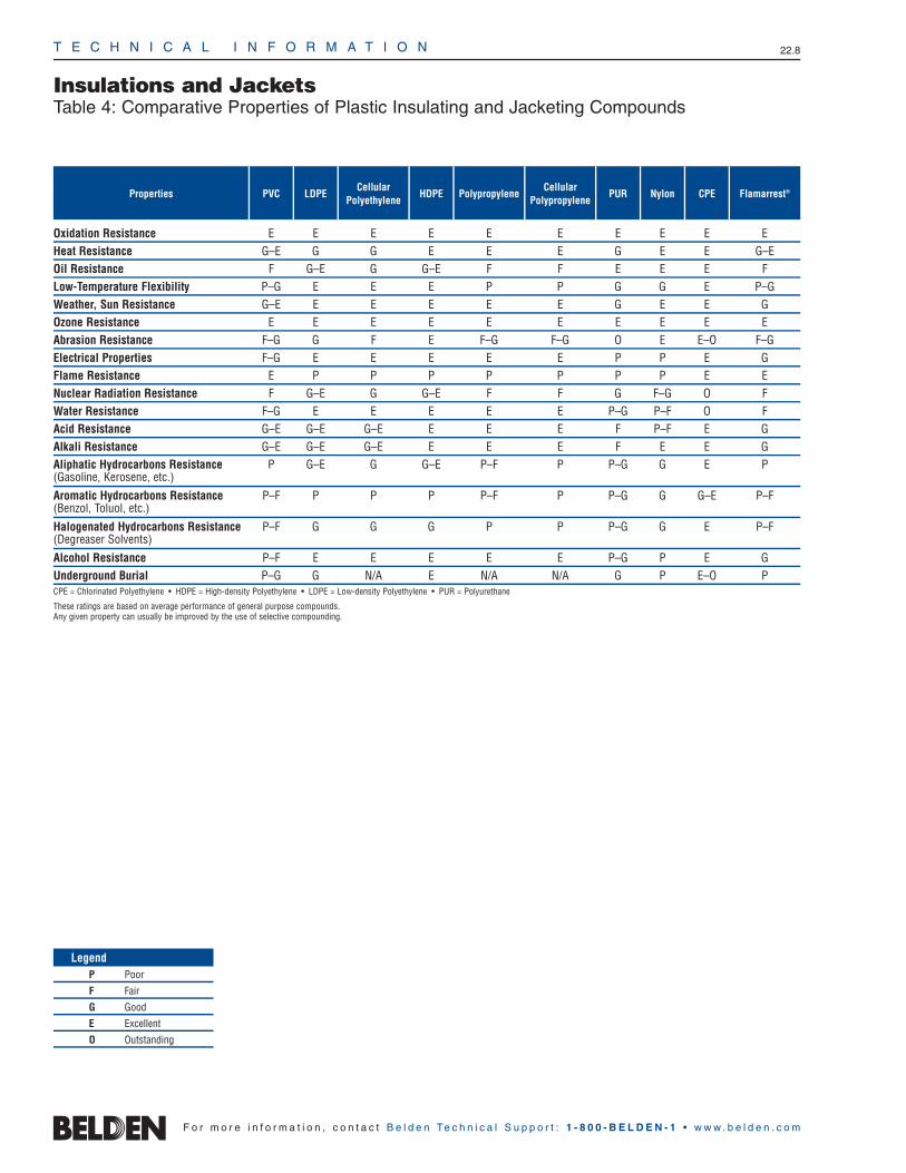
Insulations and JacketsTable 4: Comparative Properties of Plastic Insulating and Jacketing Compounds
T E C H N I C A L I N F O R M A T I O N 22.8
F o r m o r e i n f o r m a t i o n , c o n t a c t B e l d e n Te c h n i c a l S u p p o r t : 1 - 8 0 0 - B E L D E N - 1 • w w w . b e l d e n . c o m
Oxidation Resistance E E E E E E E E E EHeat Resistance G–E G G E E E G E E G–EOil Resistance F G–E G G–E F F E E E FLow-Temperature Flexibility P–G E E E P P G G E P–GWeather, Sun Resistance G–E E E E E E G E E GOzone Resistance E E E E E E E E E EAbrasion Resistance F–G G F E F–G F–G O E E–O F–GElectrical Properties F–G E E E E E P P E GFlame Resistance E P P P P P P P E ENuclear Radiation Resistance F G–E G G–E F F G F–G O FWater Resistance F–G E E E E E P–G P–F O FAcid Resistance G–E G–E G–E E E E F P–F E GAlkali Resistance G–E G–E G–E E E E F E E GAliphatic Hydrocarbons Resistance P G–E G G–E P–F P P–G G E P(Gasoline, Kerosene, etc.)
Aromatic Hydrocarbons Resistance P–F P P P P–F P P–G G G–E P–F(Benzol, Toluol, etc.)
Halogenated Hydrocarbons Resistance P–F G G G P P P–G G E P–F(Degreaser Solvents)
Alcohol Resistance P–F E E E E E P–G P E GUnderground Burial P–G G N/A E N/A N/A G P E–O PCPE = Chlorinated Polyethylene • HDPE = High-density Polyethylene • LDPE = Low-density Polyethylene • PUR = Polyurethane
These ratings are based on average performance of general purpose compounds. Any given property can usually be improved by the use of selective compounding.
Properties Flamarrest®CPENylonPURCellular
PolypropylenePolypropyleneHDPE
CellularPolyethylene
LDPEPVC
LegendP Poor
F Fair
G Good
E Excellent
O Outstanding

T E C H N I C A L I N F O R M A T I O N 22.9
22 •
Tech
nica
l Inf
orm
atio
n
F o r m o r e i n f o r m a t i o n , c o n t a c t B e l d e n Te c h n i c a l S u p p o r t : 1 - 8 0 0 - B E L D E N - 1 • w w w . b e l d e n . c o m
Properties
Insulations and JacketsTable 5: Comparative Properties of Fluoropolymer Insulating and Jacketing Compounds
Oxidation Resistance O E O O OHeat Resistance O E O O OOil Resistance O E E–O E OLow-Temperature Flexibility O E O F OWeather, Sun Resistance O E O E–O OOzone Resistance E E O E EAbrasion Resistance E E O E EElectrical Properties E E E G–E EFlame Resistance O G E E E–ONuclear Radiation Resistance P–G E P E EWater Resistance E E E E EAcid Resistance E E E G–E EAlkali Resistance E E E E EAliphatic Hydrocarbons Resistance E E E E E(Gasoline, Kerosene, etc.)
Aromatic Hydrocarbons Resistance E E E G–E E(Benzol, Toluol, etc.)
Halogenated Hydrocarbons Resistance E E E G E(Degreaser Solvents)
Alcohol Resistance E E E E EUnderground Burial E E E E EThese ratings are based on average performance of general purpose compounds. Any given property can usually be improved by the use of selective compounding.
FEP Teflon®
Tefzel®
(ETFE)PTFETeflon
Solef® / Kynar®
(PVDF) / PVFHalar®
(E-CTFE)
LegendP Poor
F Fair
G Good
E Excellent
O Outstanding
Teflon and Tefzel are DuPont trademarks.Halar is a Solvay Solexis trademark.Solef is a Solvay trademark.Kynar is a Atofina Chemical Corporation trademark.
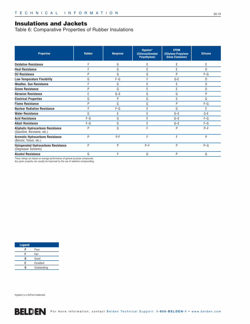
Insulations and JacketsTable 6: Comparative Properties of Rubber Insulations
T E C H N I C A L I N F O R M A T I O N 22.10
F o r m o r e i n f o r m a t i o n , c o n t a c t B e l d e n Te c h n i c a l S u p p o r t : 1 - 8 0 0 - B E L D E N - 1 • w w w . b e l d e n . c o m
Properties Rubber NeopreneHypalon®
(ChlorosulfonatedPolyethylene)
EPDM(Ethylene-Propylene-
Diene Elastomer)Silicone
Oxidation Resistance F G E E EHeat Resistance F G E E OOil Resistance P G G P F–GLow-Temperature Flexibility G F–G F G-E OWeather, Sun Resistance F G E E OOzone Resistance P G E E OAbrasion Resistance E G–E G G PElectrical Properties G P G E GFlame Resistance P G G P F–GNuclear Radiation Resistance F F–G E G EWater Resistance G E E G–E G-EAcid Resistance F–G G E G–E F–GAlkali Resistance F–G G E G–E F–GAliphatic Hydrocarbons Resistance P G F P P–F(Gasoline, Kerosene, etc.)
Aromatic Hydrocarbons Resistance P P-F F F P(Benzol, Toluol, etc.)
Halogenated Hydrocarbons Resistance P P P–F P P–G(Degreaser Solvents)
Alcohol Resistance G F G P GThese ratings are based on average performance of general purpose compounds. Any given property can usually be improved by the use of selective compounding.
LegendP Poor
F Fair
G Good
E Excellent
O Outstanding
Hypalon is a DuPont trademark.

T E C H N I C A L I N F O R M A T I O N 22.11
22 •
Tech
nica
l Inf
orm
atio
n
F o r m o r e i n f o r m a t i o n , c o n t a c t B e l d e n Te c h n i c a l S u p p o r t : 1 - 8 0 0 - B E L D E N - 1 • w w w . b e l d e n . c o m
Insulations and JacketsTable 7: Nominal Temperature Range for Various Insulating and Jacketing Compounds
Hypalon, Teflon and Tefzel are DuPont trademarks.Halar is a Solvay Solexis trademark.Solef is a Solvay trademark.Kynar is a Atofina Chemical Corporation trademark.
Chlorosulfonated Polyethylene (Hypalon®) -20°C 90°C -40°C 105°CEPDM (Ethylene-Propylene-Diene Monomer) -55°C 105°C — 150°CNeoprene -20°C 60°C -55°C 90°CPolyethylene (Solid and Foamed) -60°C 80°C — —Polypropylene (Solid and Foamed) -40°C 105°C — —Rubber -30°C 60°C -55°C 75°CFEP Teflon® -70°C 200°C — —PVC -20°C 80°C -55°C 105°CSilicone -80°C 150°C — 200°CHalar® -70°C 150°C — —Tefzel® -65°C 150°C — —PTFE Teflon -70°C 260°C — —CPE -35°C 90°C -45°C 105°CSolef® / Kynar® -20°C 150°/125°C -40°C 150°/150°CFlamarrest® -20°C 75°C — —
Compound Normal Low Normal High Special Low Special High

T E C H N I C A L I N F O R M A T I O N 22.12
Shielding and ArmoringOverview
F o r m o r e i n f o r m a t i o n , c o n t a c t B e l d e n Te c h n i c a l S u p p o r t : 1 - 8 0 0 - B E L D E N - 1 • w w w . b e l d e n . c o m
Innovative Leadership
The evolution of technology maintainssteady demand for sophisticated cableshielding. Belden meets that demand with innovative shielding and shield effectiveness testing methods to supply you with high quality, dependable cable.
With the creation of trademarked shielddesigns and patented test methods, Beldenhas earned a reputation for innovation andleadership that is unequaled in the wire andcable industry. In addition, Belden offers thebroadest line of shielded multi-conductor,coaxial and flat cable in the industry.
Several unique Belden innovations are utilized across a wide range of shieldingapplications:
Beldfoil® — The first aluminum/polyester foil developed for use as acable shield. Provides 100% shield coverage for optimum protection.
Duofoil® — Consists of an aluminum-poly-aluminum laminate wrapped aroundthe cable’s dielectric core. Provides 100%physical coverage, and improves shieldreliability and flex life.
Belden also utilizes a number of innovative techniques to apply shielding to multi-conductor and paired cables:
“French Braid” Shields — Belden’s patented “French Braid” shieldis a double spiral (double serve shield)with the two spirals tied together by one weave.
Shorting Fold — Belden uses ashorting fold technique to maintainmetal-to-metal contact for improvedhigh frequency performance. Withoutthe shorting fold, a slot is createdthrough which signals can leak andcause interference. (See Figures 1 and 2 above.)
Z-Fold® — Belden improves on the traditional shorting fold by employing a Z-Fold designed for use in multi-pairapplications to reduce crosstalk. The Z-Fold (see Figure 3) combines an isolation and a shorting fold. The shorting fold provides metal-to-metalcontact while the isolation fold keepsshields from shorting to one another inmulti-pair, individually shielded cables.
The use of either a shorting fold or a Z-Fold increases the foil shield’s range of effectiveness to higher frequencies.
Figure 1: Foil shield configurations without shorting folds.
Figure 2: Foil shield configuration with shorting fold.
Belden’s patented “French Braid” shield.
Figure 3: Foil shield with Z-Fold reduces crosstalk in multi-pair applications.
Drain Wire
InsulatedConductor
Aluminum
ShortingFold
InsulatingFilm
Aluminum
Insulating Film
Drain Wire
ShortingFold
InsulatedConductor
Isolation Fold
Drain Wire Drain Wire
InsulatedConductor
Slot Slot
Insulating Film
AluminumFoil Out Foil In

T E C H N I C A L I N F O R M A T I O N 22.13
Shielding and ArmoringCharacteristics of Belden® Shield Types and Armor Styles
22 •
Tech
nica
l Inf
orm
atio
n
F o r m o r e i n f o r m a t i o n , c o n t a c t B e l d e n Te c h n i c a l S u p p o r t : 1 - 8 0 0 - B E L D E N - 1 • w w w . b e l d e n . c o m
Foil Shields
Foil shields consist of aluminum foil laminated to a polyester or polypropylenefilm. The film gives the shield mechanicalstrength and bonus insulation. Foil shieldsprovide 100% cable coverage, necessaryfor electrostatic shield protection. Becauseof their small size, foil shields are commonlyused to shield individual pairs of multi-pairdata cables to reduce crosstalk. They haveless weight, bulk and cost less than spiralor braid shields and are generally moreeffective than braid shields in RF ranges.Foil shields are more flexible than braid buthave a shorter flex life than spiral or braid.
Drain wires areused with foilshields to maketermination easierand to ground electrostatic discharges. Theshortcomings in using the foil shield includehigher DC resistance and lower mechanicalstrength than braid or spiral shields.
Braid Shields
A braid shield consists of groups of tinnedor bare copper or aluminum strands, oneset woven in a clockwise direction andinterwoven with another set in a counter-clockwise direction.
Braid shields providesuperior structuralintegrity, while main-taining good flexibility and flex life. These shields are ideal for minimizing low frequency interference and have lowerDC resistance than foil. Braid shields areeffective at audio, as well as RF ranges.Generally, the higher the braid coverage,the more effective the shield. However, the trade-off between cost and braid coverage must be considered. Typical braid coverages are between 80% and95%. Coverage of 100% is unattainablewith a braid shield. Other features to consider when choosing a braid shield are the weave angle, strand diameter, number of carriers (strand groups) and the number of ends (strands).
Braid shields are generally bulkier andheavier than other shields and, in somecases, harder to terminate because thebraid may be combed out and pigtailed.
Spiral/Serve Shields
A spiral/serve shield consists of wire (usuallycopper) wrapped in a spiral around the innercable core.
Superior flexibilityand flex life, easeof termination andup to 97% coverage are the advantages of spiral shields. They are best suited foraudio applications. As a rule, spiral shieldsare not effective above the audio frequencyrange due to the coil effect produced by theinductance of served wire strands.
“French Braid” Shields
Belden’s patented “French Braid” shield isa double spiral (double serve shield) withthe two spirals tied together by one weave.This construction provides improved flexlife over standard spiral shields, improvedflexibility overconventionalbraid shields, and lower levelsof microphonic or triboelectric noise thaneither spiral or conventional braid shields.
Combination Shields
Combination shields consist of more than one layer of shielding. They providemaximum shield efficiency across the frequency spectrum. The combinationfoil/braid shield combines the advantages of 100% foil coverage, plus the strengthand low DC resistance of the braid.
Belden has also developed a number of shielding configurations for use withbroadband coaxial cables.
Duobond®
Duobond is essentially the same construction as Duofoil® (a laminatedtape of foil/film/foil), but with an extralayer of adhesive bonding the foil shieldto the dielectric core. This foil shieldprovides 100% coverage and insuresmaximum shield protection.
Duobond II (Foil/Braid) Combines Duobond with an outer braid,applied for greater protection againstinterference and to increase the overalltensilestrength.
Duobond III (Tri-Shield) Utilizes the Duobond II design(foil/braid) plus a surrounding layer ofDuofoil. The extra foil layer improvesshield reliability and provides an additionalinterferencebarrier.
Duobond Plus® — Featuresfoil/braid/foil construction with a shorting fold in the outermost foil. This fold prevents a slot opening frombeing created in the shield, thereby preventingsignalegress oringress.
Duobond IV (Quad Shield) Offers an extra layer of braid shield(foil/braid/foil/braid) for improvedstrength and durability.
Other combination shields are availablesuch as the foil/braid/foil/braid used on theEthernet cables, braid/braid or foil/spiral.
Armoring
Belden’s innovative technology deliversmaximum effectiveness to meet the per-formance requirements of a wide range ofapplications.
Belden also has the capability to protectelectronic, instrumentation, and controlcables with interlocking steel or aluminumarmor.
Shorting Fold

T E C H N I C A L I N F O R M A T I O N 22.14
Shielding and ArmoringShield Types Application Guide, Table 8: Relative Cost Comparison of Shield TypesTable 9: Shield Performance Ratings
F o r m o r e i n f o r m a t i o n , c o n t a c t B e l d e n Te c h n i c a l S u p p o r t : 1 - 8 0 0 - B E L D E N - 1 • w w w . b e l d e n . c o m
Shield Types Application Guide
Choose a Foil Shield…
For protection against capacitive (electric field) coupling where shieldcoverage is more important than low DC resistance.
When possible sources of interferenceinclude TV signals, crosstalk from othercircuits, radio transmitters, fluorescentlights or computing equipment.
For MATV, CATV, video, networking,computer I/O cables in office, industrialor commercial environments where ambient EMI levels are low.
Choose a Braid Shield…
For superior performance against diffu-sion coupling, where low DC resistanceis important, and to a lesser extent,capacitive and inductive coupling.
When possible sources of interferenceexhibit low impedance characteristics,such as motor control circuits andswitches which operate inductive loads.
For computer to terminal interconnectfor process, instrumentation or controlapplications.
Choose a Spiral Shield…
For functional shielding against diffusion and capacitive coupling at audio frequencies only.
When possible sources of interferenceare power lines and fluorescent lights.
For applications when flexibility and flex life are major concerns, such asmicrophone and audio cables andretractile cords.
Choose a Combination Shield…
For shielding against high frequencyradiated emissions coupling and ESD.Combines the low resistance of braidand 100% coverage of foil shields.
When possible sources of interferenceinclude radio transmitters, TV stations,printed circuit boards, back planes,motor control circuits and computingequipment.
For Video, CATV, MATV, networking,computer I/O cables and computer-aided manufacturing applications.
Table 8: Relative Cost Comparison
Relative cost comparisons are based oncoaxial cable. Chart shows relative shieldcost as one component of the total cost ofthe cable. These cost ratings may changedepending on the physical construction ofthe cable.
5
4
3
2
1
0Braid Spiral Foil Foil/Braid Duobond Plus® Quad
Frequency: DCCapacitive A AA AAA AAA AAADiffusion AAA A C AAA AAADiffusion/Inductive — — — — —Diffusion/Inductive/Capacitive — — — — —Frequency: 15 kHz
Capacitive A AA AAA AAA AAADiffusion AAA B C AAA AAADiffusion/Inductive AA C A AA AAADiffusion/Inductive/Capacitive — — — — —Frequency: 10 MHz to 1000 MHz
Capacitive A AA AAA AAA AAADiffusion — — — — —Diffusion/Inductive B C A AA AAADiffusion/Inductive/Capacitive B C A AA AAA*Although ratings shown in Table 9 are based on shielded coaxial cable test results, these ratings also pertain to shielded multi-conductor and flat cable where shield types are available.
Note: Shield effectiveness decreases as frequency increases. Therefore, ratings in one frequency category do not imply equal shield effectiveness in other frequency categories.
Frequency Range and Types of Interference
Anticipated
Cable Shield Ratings*
Braid(95% Coverage) Spiral Foil Foil/Braid
Foil/Braid/FoilDuobond Plus®
Shield Rating KeyAAA Best
AA Better
A Good
B Functional
C Unsatisfactory
— Not Applicable
Table 9: Shield Performance Comparison Chart

T E C H N I C A L I N F O R M A T I O N 22.15
Metric ConversionsTable 10: Temperature Conversion Chart and FormulaTable 11: Distance and Weight Conversion Formulas
22 •
Tech
nica
l Inf
orm
atio
n
F o r m o r e i n f o r m a t i o n , c o n t a c t B e l d e n Te c h n i c a l S u p p o r t : 1 - 8 0 0 - B E L D E N - 1 • w w w . b e l d e n . c o m
°C °F210 410205 401200 392195 383190 374185 365180 356175 347170 338165 329160 320155 311150 302145 293140 284135 275130 266
°C °F125 257120 248115 239110 230105 221100 21295 20390 19485 18580 17675 16770 15865 14960 14055 13150 12245 113
°C °F40 10435 9530 8625 7720 6815 5910 505 410 32-5 23-10 14-15 5-20 -4-25 -13-30 -22-35 -31-40 -40
Temp. Conversion Formulas
°C = 5 (°F – 32)
9
°F = 9 °C + 32
5
Table 10: Temperature Conversion Chart
Table 11: Distance and Weight Conversion Formulas
To Convert: Multiply by:
Inches to millimeters 25.4
Millimeters to inches .03937
Meters to feet 3.2808
Feet to meters .3048
Kilometers to feet 3280.8
Feet to kilometers .0003048
Kilograms to pounds 2.205
Pounds to kilograms .4536
Pounds/1000 feet to pounds/1000 meters 3.2808
Pounds/1000 feet to kilograms/1000 meters 1.4882
Kilograms/1000 meters to pounds/1000 feet .6719

T E C H N I C A L I N F O R M A T I O N 22.16
Metric ConversionsTable 12: Conductor Size Equivalents (mm2/ inch2/ circular mils /AWG)
F o r m o r e i n f o r m a t i o n , c o n t a c t B e l d e n Te c h n i c a l S u p p o r t : 1 - 8 0 0 - B E L D E N - 1 • w w w . b e l d e n . c o m
Sq.mm
Sq.in.
Cir.mils.
AWG
1000 1.550 1974000975 1.511 1924700950 1.472 1875300925 1.434 1826000900 1.395 1776600875 1.356 1727300850 1.317 1677900825 1.279 1628600800 1.240 1579200775 1.201 1529900750 1.163 1480500725 1.124 1431200700 1.085 1381800675 1.046 1332500650 1.008 1283100625 .969 1233800600 .930 1184400575 .891 1135100550 .853 1085700525 .814 1036400500 .775 987000475 .736 937700450 .698 888300425 .659 839000400 .620 789600375 .581 740300350 .542 690900325 .504 641600300 .465 592200275 .426 542900250 .388 493500225 .349 444200200 .310 394800175 .271 345500150 .233 296100125 .1938 246800— — 211600 4/0
100 .1550 19740095 .1472 18753090 .1395 177660— — 167800 3/085 .1317 16779080 .1240 15792075 .1163 14805070 .1085 138180— — 133100 2/065 .1008 12831060 .0930 118440
Sq.mm
Sq.in.
Cir.mils.
AWG
55 .0853 108570— — 105600 1/050 .0775 9870045 .0698 88830— — 83690 140 .0620 7896035 .0542 69090— — 66360 230 .0465 59220— — 52620 325 .0388 49350— — 41740 4
20.0 .0310 3948019.5 .0302 3849019.0 .0294 3751018.5 .0287 3652018.0 .0279 3553017.5 .0271 3455017.0 .0264 33560
— — 33090 516.5 .0256 3256016.0 .0248 3158015.5 .0240 3060015.0 .0233 2961014.5 .0225 2862014.0 .0217 2764013.5 .0209 26650
— — 26420 613.0 .0201 2566012.5 .0194 2468012.0 .0186 2369011.5 .0178 2270011.0 .0171 21710
— — 20820 710.5 .0163 2073010.0 .0155 197409.5 .01472 187539.0 .01395 177668.5 .01317 16779— — 16510 88.0 .01240 157927.5 .01163 148057.0 .01085 13818— — 13090 96.5 .01008 128316.0 .00930 118445.5 .00853 10857— — 10380 10
Sq.mm
Sq.in.
Cir.mils.
AWG
5.00 .00775 98704.75 .00736 93774.50 .00698 88834.25 .00659 8390
— — 8230 114.00 .00620 78963.75 .00581 74033.50 .00542 6909
— — 6530 123.25 .00504 64163.00 .00465 59222.75 .00426 5429
— — 5180 132.50 .00388 49352.25 .00349 4422
— — 4110 142.00 .00310 39481.75 .00271 3455
— — 3260 151.50 .00233 2961
— — 2580 161.25 .00194 2468
— — 2050 171.00 .00155 1974.90 .00140 1777— — 1620 18.80 .00124 1579.75 .00116 1481.70 .00109 1382— — 1290 19.60 .00093 1184— — 1029 20.50 .000775 987
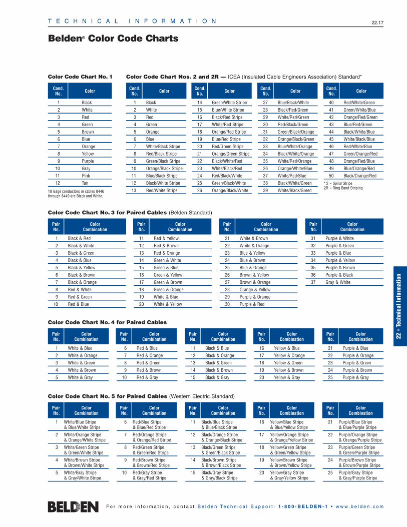
T E C H N I C A L I N F O R M A T I O N 22.17
22 •
Tech
nica
l Inf
orm
atio
n
F o r m o r e i n f o r m a t i o n , c o n t a c t B e l d e n Te c h n i c a l S u p p o r t : 1 - 8 0 0 - B E L D E N - 1 • w w w . b e l d e n . c o m
Belden® Color Code Charts
1 Black
2 White
3 Red
4 Green
5 Brown
6 Blue
7 Orange
8 Yellow
9 Purple
10 Gray
11 Pink
12 Tan
18 Gage conductors in cables 8446through 8449 are Black and White.
Color Code Chart No. 3 for Paired Cables (Belden Standard)
Color Code Chart No. 4 for Paired Cables
Color Code Chart No. 5 for Paired Cables (Western Electric Standard)
Color Code Chart No. 1 Color Code Chart Nos. 2 and 2R — ICEA (Insulated Cable Engineers Association) Standard*
1 Black & Red
2 Black & White
3 Black & Green
4 Black & Blue
5 Black & Yellow
6 Black & Brown
7 Black & Orange
8 Red & White
9 Red & Green
10 Red & Blue
11 Red & Yellow
12 Red & Brown
13 Red & Orange
14 Green & White
15 Green & Blue
16 Green & Yellow
17 Green & Brown
18 Green & Orange
19 White & Blue
20 White & Yellow
21 White & Brown
22 White & Orange
23 Blue & Yellow
24 Blue & Brown
25 Blue & Orange
26 Brown & Yellow
27 Brown & Orange
28 Orange & Yellow
29 Purple & Orange
30 Purple & Red
31 Purple & White
32 Purple & Green
33 Purple & Blue
34 Purple & Yellow
35 Purple & Brown
36 Purple & Black
37 Gray & White
Cond.No. Color
PairNo.
ColorCombination
PairNo.
ColorCombination
PairNo.
ColorCombination
PairNo.
ColorCombination
PairNo.
ColorCombination
PairNo.
ColorCombination
PairNo.
ColorCombination
PairNo.
ColorCombination
PairNo.
ColorCombination
PairNo.
ColorCombination
PairNo.
ColorCombination
PairNo.
ColorCombination
PairNo.
ColorCombination
PairNo.
ColorCombination
Cond.No. Color Cond.
No. Color Cond.No. Color Cond.
No. Color
1 White & Blue
2 White & Orange
3 White & Green
4 White & Brown
5 White & Gray
6 Red & Blue
7 Red & Orange
8 Red & Green
9 Red & Brown
10 Red & Gray
11 Black & Blue
12 Black & Orange
13 Black & Green
14 Black & Brown
15 Black & Gray
16 Yellow & Blue
17 Yellow & Orange
18 Yellow & Green
19 Yellow & Brown
20 Yellow & Gray
21 Purple & Blue
22 Purple & Orange
23 Purple & Green
24 Purple & Brown
25 Purple & Gray
1 White/Blue Stripe & Blue/White Stripe
2 White/Orange Stripe & Orange/White Stripe
3 White/Green Stripe & Green/White Stripe
4 White/Brown Stripe & Brown/White Stripe
5 White/Gray Stripe & Gray/White Stripe
6 Red/Blue Stripe& Blue/Red Stripe
7 Red/Orange Stripe& Orange/Red Stripe
8 Red/Green Stripe& Green/Red Stripe
9 Red/Brown Stripe& Brown/Red Stripe
10 Red/Gray Stripe& Gray/Red Stripe
11 Black/Blue Stripe& Blue/Black Stripe
12 Black/Orange Stripe& Orange/Black Stripe
13 Black/Green Stripe& Green/Black Stripe
14 Black/Brown Stripe& Brown/Black Stripe
15 Black/Gray Stripe& Gray/Black Stripe
16 Yellow/Blue Stripe& Blue/Yellow Stripe
17 Yellow/Orange Stripe& Orange/Yellow Stripe
18 Yellow/Green Stripe& Green/Yellow Stripe
19 Yellow/Brown Stripe& Brown/Yellow Stripe
20 Yellow/Gray Stripe& Gray/Yellow Stripe
21 Purple/Blue Stripe& Blue/Purple Stripe
22 Purple/Orange Stripe& Orange/Purple Stripe
23 Purple/Green Stripe& Green/Purple Stripe
24 Purple/Brown Stripe& Brown/Purple Stripe
25 Purple/Gray Stripe& Gray/Purple Stripe
1 Black
2 White
3 Red
4 Green
5 Orange
6 Blue
7 White/Black Stripe
8 Red/Black Stripe
9 Green/Black Stripe
10 Orange/Black Stripe
11 Blue/Black Stripe
12 Black/White Stripe
13 Red/White Stripe
14 Green/White Stripe
15 Blue/White Stripe
16 Black/Red Stripe
17 White/Red Stripe
18 Orange/Red Stripe
19 Blue/Red Stripe
20 Red/Green Stripe
21 Orange/Green Stripe
22 Black/White/Red
23 White/Black/Red
24 Red/Black/White
25 Green/Black/White
26 Orange/Black/White
27 Blue/Black/White
28 Black/Red/Green
29 White/Red/Green
30 Red/Black/Green
31 Green/Black/Orange
32 Orange/Black/Green
33 Blue/White/Orange
34 Black/White/Orange
35 White/Red/Orange
36 Orange/White/Blue
37 White/Red/Blue
38 Black/White/Green
39 White/Black/Green
40 Red/White/Green
41 Green/White/Blue
42 Orange/Red/Green
43 Blue/Red/Green
44 Black/White/Blue
45 White/Black/Blue
46 Red/White/Blue
47 Green/Orange/Red
48 Orange/Red/Blue
49 Blue/Orange/Red
50 Black/Orange/Red
* 2 = Spiral Stripe2R = Ring Band Striping
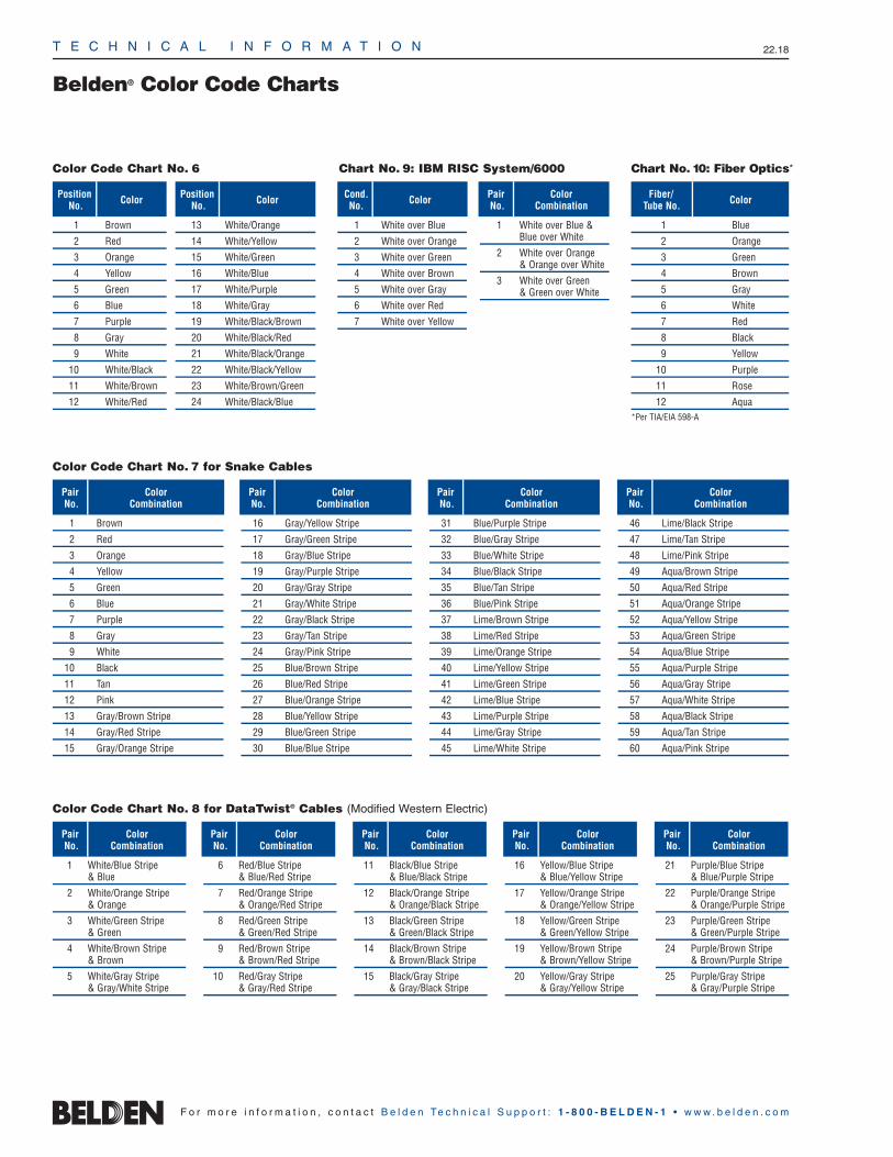
Belden® Color Code Charts
T E C H N I C A L I N F O R M A T I O N 22.18
F o r m o r e i n f o r m a t i o n , c o n t a c t B e l d e n Te c h n i c a l S u p p o r t : 1 - 8 0 0 - B E L D E N - 1 • w w w . b e l d e n . c o m
Color Code Chart No. 7 for Snake Cables
1 Brown
2 Red
3 Orange
4 Yellow
5 Green
6 Blue
7 Purple
8 Gray
9 White
10 Black
11 Tan
12 Pink
13 Gray/Brown Stripe
14 Gray/Red Stripe
15 Gray/Orange Stripe
16 Gray/Yellow Stripe
17 Gray/Green Stripe
18 Gray/Blue Stripe
19 Gray/Purple Stripe
20 Gray/Gray Stripe
21 Gray/White Stripe
22 Gray/Black Stripe
23 Gray/Tan Stripe
24 Gray/Pink Stripe
25 Blue/Brown Stripe
26 Blue/Red Stripe
27 Blue/Orange Stripe
28 Blue/Yellow Stripe
29 Blue/Green Stripe
30 Blue/Blue Stripe
31 Blue/Purple Stripe
32 Blue/Gray Stripe
33 Blue/White Stripe
34 Blue/Black Stripe
35 Blue/Tan Stripe
36 Blue/Pink Stripe
37 Lime/Brown Stripe
38 Lime/Red Stripe
39 Lime/Orange Stripe
40 Lime/Yellow Stripe
41 Lime/Green Stripe
42 Lime/Blue Stripe
43 Lime/Purple Stripe
44 Lime/Gray Stripe
45 Lime/White Stripe
46 Lime/Black Stripe
47 Lime/Tan Stripe
48 Lime/Pink Stripe
49 Aqua/Brown Stripe
50 Aqua/Red Stripe
51 Aqua/Orange Stripe
52 Aqua/Yellow Stripe
53 Aqua/Green Stripe
54 Aqua/Blue Stripe
55 Aqua/Purple Stripe
56 Aqua/Gray Stripe
57 Aqua/White Stripe
58 Aqua/Black Stripe
59 Aqua/Tan Stripe
60 Aqua/Pink Stripe
PairNo.
ColorCombination
PairNo.
ColorCombination
PairNo.
ColorCombination
PairNo.
ColorCombination
Color Code Chart No. 8 for DataTwist® Cables (Modified Western Electric)
PairNo.
ColorCombination
PairNo.
ColorCombination
PairNo.
ColorCombination
PairNo.
ColorCombination
PairNo.
ColorCombination
1 White/Blue Stripe& Blue
2 White/Orange Stripe& Orange
3 White/Green Stripe& Green
4 White/Brown Stripe& Brown
5 White/Gray Stripe& Gray/White Stripe
6 Red/Blue Stripe& Blue/Red Stripe
7 Red/Orange Stripe& Orange/Red Stripe
8 Red/Green Stripe& Green/Red Stripe
9 Red/Brown Stripe& Brown/Red Stripe
10 Red/Gray Stripe& Gray/Red Stripe
11 Black/Blue Stripe& Blue/Black Stripe
12 Black/Orange Stripe& Orange/Black Stripe
13 Black/Green Stripe& Green/Black Stripe
14 Black/Brown Stripe& Brown/Black Stripe
15 Black/Gray Stripe& Gray/Black Stripe
16 Yellow/Blue Stripe& Blue/Yellow Stripe
17 Yellow/Orange Stripe& Orange/Yellow Stripe
18 Yellow/Green Stripe& Green/Yellow Stripe
19 Yellow/Brown Stripe& Brown/Yellow Stripe
20 Yellow/Gray Stripe& Gray/Yellow Stripe
21 Purple/Blue Stripe& Blue/Purple Stripe
22 Purple/Orange Stripe& Orange/Purple Stripe
23 Purple/Green Stripe& Green/Purple Stripe
24 Purple/Brown Stripe& Brown/Purple Stripe
25 Purple/Gray Stripe& Gray/Purple Stripe
1 Brown
2 Red
3 Orange
4 Yellow
5 Green
6 Blue
7 Purple
8 Gray
9 White
10 White/Black
11 White/Brown
12 White/Red
13 White/Orange
14 White/Yellow
15 White/Green
16 White/Blue
17 White/Purple
18 White/Gray
19 White/Black/Brown
20 White/Black/Red
21 White/Black/Orange
22 White/Black/Yellow
23 White/Brown/Green
24 White/Black/Blue
Color Code Chart No. 6 Chart No. 9: IBM RISC System/6000
PositionNo. Color Position
No. Color Cond.No. Color Pair
No.Color
Combination
1 White over Blue
2 White over Orange
3 White over Green
4 White over Brown
5 White over Gray
6 White over Red
7 White over Yellow
1 White over Blue &Blue over White
2 White over Orange& Orange over White
3 White over Green& Green over White
1 Blue
2 Orange
3 Green
4 Brown
5 Gray
6 White
7 Red
8 Black
9 Yellow
10 Purple
11 Rose
12 Aqua*Per TIA/EIA 598-A
Chart No. 10: Fiber Optics*
Fiber/Tube No. Color
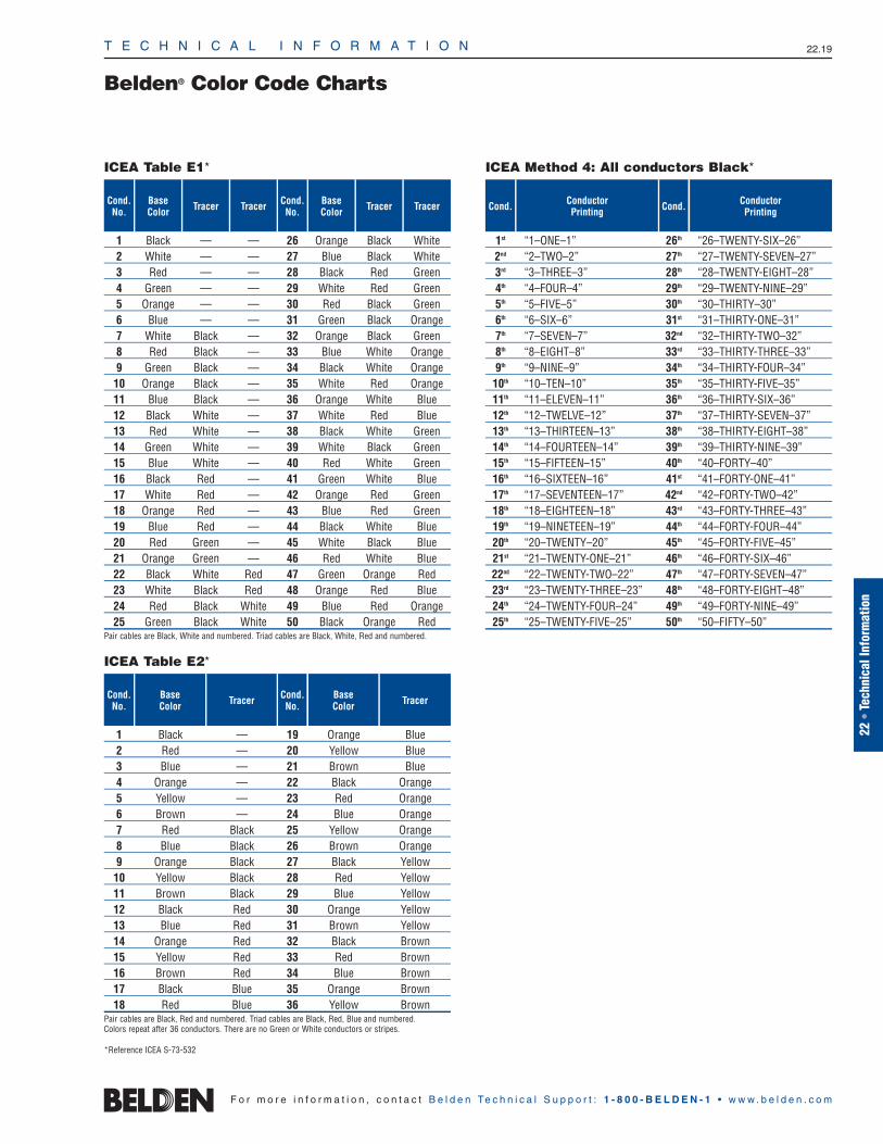
T E C H N I C A L I N F O R M A T I O N 22.19
Belden® Color Code Charts
22 •
Tech
nica
l Inf
orm
atio
n
F o r m o r e i n f o r m a t i o n , c o n t a c t B e l d e n Te c h n i c a l S u p p o r t : 1 - 8 0 0 - B E L D E N - 1 • w w w . b e l d e n . c o m
BaseColorTracer
TracerTracerBaseColor
Cond.No.TracerTracerBase
ColorCond.No.
1 Black — — 26 Orange Black White2 White — — 27 Blue Black White3 Red — — 28 Black Red Green4 Green — — 29 White Red Green5 Orange — — 30 Red Black Green6 Blue — — 31 Green Black Orange7 White Black — 32 Orange Black Green8 Red Black — 33 Blue White Orange9 Green Black — 34 Black White Orange10 Orange Black — 35 White Red Orange11 Blue Black — 36 Orange White Blue12 Black White — 37 White Red Blue13 Red White — 38 Black White Green14 Green White — 39 White Black Green15 Blue White — 40 Red White Green16 Black Red — 41 Green White Blue17 White Red — 42 Orange Red Green18 Orange Red — 43 Blue Red Green19 Blue Red — 44 Black White Blue20 Red Green — 45 White Black Blue21 Orange Green — 46 Red White Blue22 Black White Red 47 Green Orange Red23 White Black Red 48 Orange Red Blue24 Red Black White 49 Blue Red Orange25 Green Black White 50 Black Orange Red
Pair cables are Black, White and numbered. Triad cables are Black, White, Red and numbered.
ICEA Table E1*
Cond.No.
BaseColor
Cond.No.
1 Black — 19 Orange Blue2 Red — 20 Yellow Blue3 Blue — 21 Brown Blue4 Orange — 22 Black Orange5 Yellow — 23 Red Orange6 Brown — 24 Blue Orange7 Red Black 25 Yellow Orange8 Blue Black 26 Brown Orange9 Orange Black 27 Black Yellow10 Yellow Black 28 Red Yellow11 Brown Black 29 Blue Yellow12 Black Red 30 Orange Yellow13 Blue Red 31 Brown Yellow14 Orange Red 32 Black Brown15 Yellow Red 33 Red Brown16 Brown Red 34 Blue Brown17 Black Blue 35 Orange Brown18 Red Blue 36 Yellow Brown
Pair cables are Black, Red and numbered. Triad cables are Black, Red, Blue and numbered.Colors repeat after 36 conductors. There are no Green or White conductors or stripes.
Tracer
ICEA Table E2*
ConductorPrintingCond.Conductor
PrintingCond.
1st “1–ONE–1” 26th “26–TWENTY-SIX–26”2nd “2–TWO–2” 27th “27–TWENTY-SEVEN–27”3rd “3–THREE–3” 28th “28–TWENTY-EIGHT–28”4th “4–FOUR–4” 29th “29–TWENTY-NINE–29”5th “5–FIVE–5” 30th “30–THIRTY–30”6th “6–SIX–6” 31st “31–THIRTY-ONE–31”7th “7–SEVEN–7” 32nd “32–THIRTY-TWO–32”8th “8–EIGHT–8” 33rd “33–THIRTY-THREE–33”9th “9–NINE–9” 34th “34–THIRTY-FOUR–34”10th “10–TEN–10” 35th “35–THIRTY-FIVE–35”11th “11–ELEVEN–11” 36th “36–THIRTY-SIX–36”12th “12–TWELVE–12” 37th “37–THIRTY-SEVEN–37”13th “13–THIRTEEN–13” 38th “38–THIRTY-EIGHT–38”14th “14–FOURTEEN–14” 39th “39–THIRTY-NINE–39”15th “15–FIFTEEN–15” 40th “40–FORTY–40”16th “16–SIXTEEN–16” 41st “41–FORTY-ONE–41”17th “17–SEVENTEEN–17” 42nd “42–FORTY-TWO–42”18th “18–EIGHTEEN–18” 43rd “43–FORTY-THREE–43”19th “19–NINETEEN–19” 44th “44–FORTY-FOUR–44”20th “20–TWENTY–20” 45th “45–FORTY-FIVE–45”21st “21–TWENTY-ONE–21” 46th “46–FORTY-SIX–46”22nd “22–TWENTY-TWO–22” 47th “47–FORTY-SEVEN–47”23rd “23–TWENTY-THREE–23” 48th “48–FORTY-EIGHT–48”24th “24–TWENTY-FOUR–24” 49th “49–FORTY-NINE–49”25th “25–TWENTY-FIVE–25” 50th “50–FIFTY–50”
ICEA Method 4: All conductors Black*
*Reference ICEA S-73-532

T E C H N I C A L I N F O R M A T I O N 22.20
Cable Standards Reference Guide
F o r m o r e i n f o r m a t i o n , c o n t a c t B e l d e n Te c h n i c a l S u p p o r t : 1 - 8 0 0 - B E L D E N - 1 • w w w . b e l d e n . c o m
National Electrical Code (NEC)®
Catalog Reference Information
The National Electrical Code is a set ofguidelines describing procedures whichminimize the hazards of electrical shock,fires, and explosions caused by electricalinstallation. The text of the NEC is containedin nine chapters, each chapter broken intoindividual articles.
NEC types are acronyms consisting of a prefix describing cable type (e.g. coax,CATV, fiber optic) and a suffix indicating thetype of flame test it has passed and whereit can be installed. Articles describing wireand cable products — including requiredcable markings — are listed in the chart to the right.
Impact of the NEC
Almost everyone involved with wire andcable is affected by the National ElectricalCode. In particular, the following groups must incorporate NEC guidelines into theirwork: OEM engineers, wire and cable product engineers, distributors, installers, and architects.
Although NEC covers wire and cableinstalled in factories, office buildings, hotels,motels, apartment buildings, residences,and all cables which pass through any floor, wall, ceiling, or which travel in ducts,plenums, and other air handling spaces,eachindividual municipality, city, county, or statecan decide whether or not they wish to adoptthe 2002 NEC as law. Local authoritieshaving jurisdiction enforce their own codes.They have the right to accept or refuse anyinstallation in accordance with their ownlocal laws. One of the organizations localinspectors rely on to test wire and cable isUnderwriters Laboratories (UL).
Intended Uses of Appliance Wiring Materials (AWM)
In the past, AWM cable was incorrectly used to wire buildings—this was never itsintended use.
AWM cable is intended for internal wiring offactory-assembled, listed appliances suchas computers, business machines, ranges,washers, dryers, radios, and televisions.
In some cases, AWM cable may be usedfor external connection. In these situations,the user should be aware that AWM cabletemperatures and voltage ratings may differfrom NEC ratings.
C(UL) Certifications
UL/NEC-Approved cables may also beC(UL)/CEC-Approved as communicationscables meeting the requirements of the Bi-National Standard CSA C22.2 No. 214/UL 444 and Section 60 of the CanadianElectrical Code, Part I (CEC). The C(UL)cable designation (and its meaning) wouldbe one of the following:
1. CMP — Cable meeting CSA FT7 or NFPA 262 (UL 910);
2. CMR — Cable meeting UL 1666;
3. CMG — Cable meeting CSA FT4;
4. CM — Cable meeting UL 1685 (UL 1581,Sec. 1160) Vertical-Tray;
5. CMX — meeting UL 1581, Sec. 1080 (VW-1);
6. CMH — Cable meeting CSA FT1.
NOTE: The CSA flame tests are defined in CSA C22.2 No. 0.3 as follows:
FT1 Vertical Flame Test —per C.S.A. C22.2 No. 0.3-92 Para 4.11.1
A finished cable shall not propagate aflame or continue to burn for more than one(1) minute after five (5) fifteen (15) secondapplications of the test flame. There is aninterval of fifteen (15) seconds betweenflame applications. The flame test shall beperformed in accordance with Para 4.11.1of Canadian Standards Association (CSA)Standard C22.2 No. 0.3. In addition, if morethan 25% of the indicator flag is burned,the test cable fails.
FT4 Vertical Flame Test — Cables in Cable Trays per C.S.A. C22.2 No. 0.3-92 Para 4.11.4
The FT4 Vertical Flame Test — Cables in Cable Trays is similar to the UL-1685Vertical Tray Flame Test, but is more severe.The FT4 test has its burner mounted at 20°from the horizontal with the burner portsfacing up. The UL-1685 Vertical Tray hasits burner at 0° from the horizontal. TheFT4 samples must be larger than 13mm(.512″) in diameter.
If not, then the cable samples are groupedin units of at least three (3) to obtain agrouped overall diameter of 13mm. TheUL-1581 Vertical Tray does not distinguishon cable size. The FT4 has a maximum charheight of 1.5 m (59″) measured from thelower edge of the burner face. The UL-1685has a flame height allowable up to approxi-mately 78″ measured from the burner.
FT6 Horizontal Flame & Smoke Test— per C.S.A. C22.2 No. 0.3-92 Appendix B
Belden® products passing the FT6 HorizontalFlame and Smoke Test are designated FT6in the column where the trade numberappears. This test is for cables which mustpass a Horizontal Flame and Smoke Test in accordance with ANSI/NFPA Standard262-1985 (UL-910). The maximum flamespread shall be 1.50 meters (4.92 ft.). Thesmoke density shall be 0.5 at peak opticaldensity and 0.15 at maximum average optical density.
725 CL2 Class 2 cables CL2P CL2R CL2 CL2X*CL3 Class 3 cables CL3P CL3R CL3 CL3X*PLTC A stand-alone class. This is (none) (none) PLTC (none)
a power limited tray cable — a CL3-type cable which can be used outdoors, is sunlight- and moisture-resistant and must pass the Vertical Tray flame test.
760 FPL Power limited, fire protective FPLP FPLR FPL (none)signaling circuit cable
770 OFC Fiber cable also containing OFCP OFCR OFCG, OFC (none)metallic conductors
OFN Fiber cable only containing OFNP OFNR OFNG, OFN (none)optical fibers
800 CM Communications CMP CMR CMG, CM CMX*MP Multi-Purpose Cables MPP MPR MPG, MP (none)
820 CATV Community antenna television CATVP CATVR CATV CATVX**and radio distribution system
830 BM Network-powered broadband BLP BMR BM BLXcommunications cable
*Cable diameter must be less than 0.250″ **Cable diameter must be less than 0.375″
Plenum Riser Commercial ResidentialNEC
Article/Type Description
National Electrical Code and NEC are registered trademarks of the National Fire Protection Association, Inc., Quincy, MA.
Installation Type

T E C H N I C A L I N F O R M A T I O N 22.21
22 •
Tech
nica
l Inf
orm
atio
n
F o r m o r e i n f o r m a t i o n , c o n t a c t B e l d e n Te c h n i c a l S u p p o r t : 1 - 8 0 0 - B E L D E N - 1 • w w w . b e l d e n . c o m
Cable Substitution ChartPer 2005 NEC®
PLENUM4 (Highest)
RISER3
GENERAL PURPOSE2
RESIDENTIAL1 (Lowest)
CMP
PLTC
CL3
CL2
FPL
CMX
CL3X
CL2X
CATVX
CATV OFNG OFCG
FPLR CATVR OFNR OFCR
CL3R
CL2R
FPLP CATVP OFNP OFCP
CL3P
CL2P
NONCONDUCTIVE CONDUCTIVE
NEC ARTICLES
770 830725800 760 820
CMR
CMGCM
Test Requirements
NFPA 262(UL-910Steiner Tunnel)
UL-1666(Vertical Shaft)
UL-1685Vertical Trayor CSA FT4(UL 1581)
VW-1(Vertical Flame)
FIRE-RESISTANCE LEVEL
BLX
All cables other than“Network-Powered Broadband Cables”
(BMR, BM, BLP, BLX)shall be coaxial cables.
BMR
BM
BLP CMPCL3P
CMRCL3RCMGCMCL3CMXCL3X
Cables indicated can be substituted.
MULTI-CONDUCTOR
MULTI-CONDUCTOR
MULTI-CONDUCTOR
COAX
COAX
COAX
COAX
NEC Type DefinitionCMP, CMR, CMG, CM, CMX Communications CablesCL3P, CL3R, CL3, CL3X, CL2P, CL2R, CL2, CL2X
Class 2 and Class 3 Remote-Control, Signaling and Power Limited Cables
FPLP, FPLR, FPL Power Limited Fire Alarm CablesCATVP, CATVR, CATV, CATVX Community Antenna Television and Radio Distribution CablesOFNP, OFNR, OFNG, OFN Nonconductive Optical Fiber CablesOFCP, OFCR, OFCG, OFC Conductive Optical Fiber CablesPLTC Power Limited Tray CablesBMR, BM, BLP, BLX Network-powered Broadband Communications Cable
National Electrical Code and NEC are registered trademarks of the National Fire Protection Association, Inc., Quincy, MA.

T E C H N I C A L I N F O R M A T I O N 22.22
F o r m o r e i n f o r m a t i o n , c o n t a c t B e l d e n Te c h n i c a l S u p p o r t : 1 - 8 0 0 - B E L D E N - 1 • w w w . b e l d e n . c o m
Canadian Electrical Code (CEC) Substitution ChartTerms of Use of Master Catalog
CMPFT6
CMRUL1666 — Riser
CMGFT4
CMUL Vertical Tray
CMXUL VW1
CMHCSA FT1
Cable Substitution Hierarchy as per C22.2 #214— Communication Cables
Canadian Electrical Code, Part 1, Table 19, Note 22:
The following cable substitution may be used:
a. Communication cables marked MPP, CMP, MPR, CMR, MPG,CMG, MP, CM, CMX, CMH, FT6, and FT4 have been found tomeet the standard criteria for FT1.
b. Communication cables marked MPP, CMP, MPR, CMR, MPG,CMG, and FT6 have been found to meet the standard criteria for FT4.
c. Communication cables marked MPP and CMP have been found to meet the standard criteria for FT6.
Terms of Use of Master Catalog
Use of Information; Disclaimers
Although Belden Electronics Division (“Belden”) makes every reasonable effort to ensure their accuracy at the time of this publication, information and specifications described in this catalogare subject to change without notice. The most current productinformation may be found by accessing our Website atwww.belden.com or contacting Belden Technical Support at 1-800-BELDEN-1.
Belden provides the information and specifications in this catalogon an “AS IS” basis, with no representations or warranties, whether express, statutory or implied. WITH RESPECT TO SUCHINFORMATION AND SPECIFICATIONS, BELDEN DISCLAIMS ALLWARRANTIES OF MERCHANTABILITY, FITNESS FOR INTENDEDPURPOSE AND NON-INFRINGEMENT. IT ALSO EXCLUDES ANYEXPRESS OR IMPLIED WARRANTIES ARISING FROM ANYCOURSE OF DEALING, USAGE, TRADE PRACTICE OR PERFORMANCE. BELDEN’S SOLE WARRANTIES ARE ASBELDEN MAY PROVIDE IN (AND SUBJECT TO THE TERMS ANDLIMITATIONS OF) SEPARATE WARRANTY DOCUMENTATION.
In no event will Belden be liable for any damages (including consequential, indirect, incidental, special, punitive, or exemplarydamages) whatsoever, even if Belden has been advised of the possibility of such damages, whether in an action under contract,negligence or any other theory, arising out of or in connection with the use, inability to use, or performance of the information, specifications or products described in this catalog.
Belden’s Terms and Conditions of Sale
All sales of Belden® products are subject to Belden’s standardterms and conditions of sale.
Intellectual Property Protection
All trademarks or registered trademarks mentioned in this catalogare property of their respective owners. The information containedin this catalog is protected by copyright. No part of this catalog maybe reproduced by any means without the prior written permissionfrom Belden.
U.S. Export Laws
The United States Export Controls laws prohibit the export of certain technical data and software to certain territories. No contentfrom this catalog may be reproduced or otherwise exported in violation of United States Law.
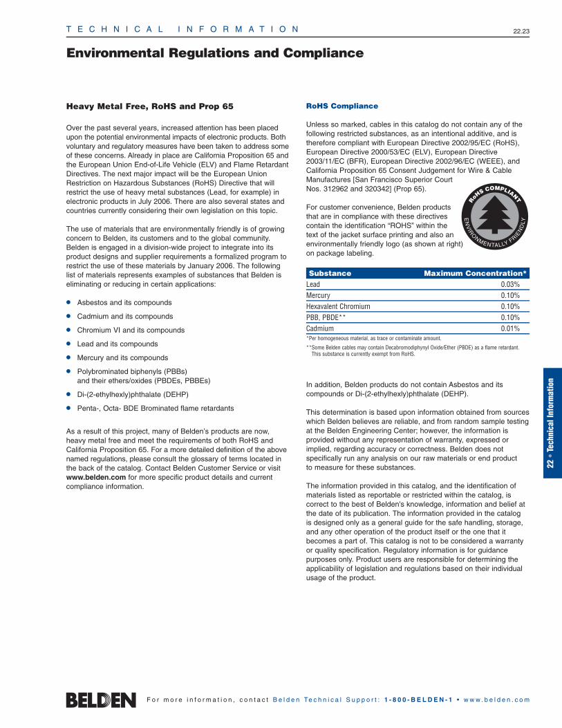
T E C H N I C A L I N F O R M A T I O N 22.23
Environmental Regulations and Compliance
22 •
Tech
nica
l Inf
orm
atio
n
F o r m o r e i n f o r m a t i o n , c o n t a c t B e l d e n Te c h n i c a l S u p p o r t : 1 - 8 0 0 - B E L D E N - 1 • w w w . b e l d e n . c o m
Heavy Metal Free, RoHS and Prop 65
Over the past several years, increased attention has been placedupon the potential environmental impacts of electronic products. Bothvoluntary and regulatory measures have been taken to address someof these concerns. Already in place are California Proposition 65 andthe European Union End-of-Life Vehicle (ELV) and Flame RetardantDirectives. The next major impact will be the European UnionRestriction on Hazardous Substances (RoHS) Directive that willrestrict the use of heavy metal substances (Lead, for example) inelectronic products in July 2006. There are also several states andcountries currently considering their own legislation on this topic.
The use of materials that are environmentally friendly is of growingconcern to Belden, its customers and to the global community.Belden is engaged in a division-wide project to integrate into itsproduct designs and supplier requirements a formalized program torestrict the use of these materials by January 2006. The followinglist of materials represents examples of substances that Belden iseliminating or reducing in certain applications:
Asbestos and its compounds
Cadmium and its compounds
Chromium VI and its compounds
Lead and its compounds
Mercury and its compounds
Polybrominated biphenyls (PBBs) and their ethers/oxides (PBDEs, PBBEs)
Di-(2-ethylhexly)phthalate (DEHP)
Penta-, Octa- BDE Brominated flame retardants
As a result of this project, many of Belden’s products are now,heavy metal free and meet the requirements of both RoHS andCalifornia Proposition 65. For a more detailed definition of the abovenamed regulations, please consult the glossary of terms located inthe back of the catalog. Contact Belden Customer Service or visitwww.belden.com for more specific product details and current compliance information.
RoHS Compliance
Unless so marked, cables in this catalog do not contain any of thefollowing restricted substances, as an intentional additive, and istherefore compliant with European Directive 2002/95/EC (RoHS),European Directive 2000/53/EC (ELV), European Directive2003/11/EC (BFR), European Directive 2002/96/EC (WEEE), andCalifornia Proposition 65 Consent Judgement for Wire & CableManufactures [San Francisco Superior Court Nos. 312962 and 320342] (Prop 65).
For customer convenience, Belden productsthat are in compliance with these directivescontain the identification “ROHS” within thetext of the jacket surface printing and also anenvironmentally friendly logo (as shown at right)on package labeling.
Substance Maximum Concentration*Lead 0.03%Mercury 0.10%Hexavalent Chromium 0.10%PBB, PBDE** 0.10%Cadmium 0.01%*Per homogeneous material, as trace or contaminate amount.
**Some Belden cables may contain Decabromodiphynyl Oxide/Ether (PBDE) as a flame retardant.This substance is currently exempt from RoHS.
In addition, Belden products do not contain Asbestos and its compounds or Di-(2-ethylhexly)phthalate (DEHP).
This determination is based upon information obtained from sourceswhich Belden believes are reliable, and from random sample testingat the Belden Engineering Center; however, the information is provided without any representation of warranty, expressed orimplied, regarding accuracy or correctness. Belden does not specifically run any analysis on our raw materials or end product to measure for these substances.
The information provided in this catalog, and the identification ofmaterials listed as reportable or restricted within the catalog, is correct to the best of Belden's knowledge, information and belief atthe date of its publication. The information provided in the catalog is designed only as a general guide for the safe handling, storage,and any other operation of the product itself or the one that itbecomes a part of. This catalog is not to be considered a warrantyor quality specification. Regulatory information is for guidance purposes only. Product users are responsible for determining theapplicability of legislation and regulations based on their individualusage of the product.

T E C H N I C A L I N F O R M A T I O N 22.24
Cable Packaging
F o r m o r e i n f o r m a t i o n , c o n t a c t B e l d e n Te c h n i c a l S u p p o r t : 1 - 8 0 0 - B E L D E N - 1 • w w w . b e l d e n . c o m
Belden, a recognized leader in state-of-the-art packaging design, has introduced avariety of packaging styles and options forthe convenience of our customers:
UnReel®
A wide variety of Belden® cable and plenum cable is available in Belden’sUnReel cardboard dispenser.
Belden UnReel is a unique packaging/dispensing system developed to save time, cut costs and labor, and eliminate the need for dereeling equipment.
Lightweight and more economical than conventional drums or reels, UnReel dispensers have pre-punched handles for easy, individual transport as well as rectangular boxes for easy pallet deliveryand storage. Unreeled cable pays outsmoothly and evenly with no kinking, twisting, or backlashing. It also rolls out60% faster per hour than conventionallypackaged cable.
UnReel ships, stores and dispenses in one carton, which — since its introduction— has always been fully recyclable andbiodegradable. Look for the letter “U” in the put-up (“Length”) description.
Reel-In-A-Box
Belden’s Reel-In-A-Box facilitates cablepayout, making installations quicker andeasier. And because it’s primarily corrugatedfiberboard material with plastic inserts, itweighs less than wooden crate reels. Thatmakes it easier to handle and dispose of,as well as less costly to ship.
A 5″ barrel, standard on every Belden®
Reel-In-A-Box, helps eliminate memory —a typical problem encountered with 3″barrels used by other manufacturers.
The new Reel-In-A-Box is extremelydurable. It has passed cold drop tests to -30°C, which translates to maximum protection on the job as well as in shipping. Look for the letter “A” in the put-up description.

T E C H N I C A L I N F O R M A T I O N 22.25
Glossary of Terms
22 •
Tech
nica
l Inf
orm
atio
n
F o r m o r e i n f o r m a t i o n , c o n t a c t B e l d e n Te c h n i c a l S u p p o r t : 1 - 8 0 0 - B E L D E N - 1 • w w w . b e l d e n . c o m
5-Mil Copper — Solid Copper Shield. Provides addedelectrical protection.
802.14 — IEEE’s Cable TV MAC and PHY ProtocolWorking Group.
10GBASE-T — IEEE standard for 10 Gigabit Ethernettransmission over copper.
10GX® — Belden’s most advanced end-to-end UTPstructured cabling system delivering guaranteedperformance of 625 MHz and data-rates of 10Gb/s.
A — Ampere.
ABR — Available Bit Rate.
Abrasion Resistance — Ability of a wire, cable or material to resist surface wear.
Abrasion Stripper — More accurately described as“buffing stripper,” which is a motorized device forremoving flat cable insulation by means of one ortwo buffing wheels that melt the insulation andbrush it away from the conductors.
AC — Alternating current. Electric current that alternates or reverses polarity in a cyclical manner (e.g. 60 Hz AC power).
Accelerated Aging — A test that simulates long timeenvironmental conditions in a relatively short time.
ACMC — Alien Crosstalk Margin Computation is thePass/Fail criteria to determine if a channel complieswith 10GBASE-T Alien noise requirements.
ACR — Attenuation Crosstalk Ratio. The differencebetween attenuation and crosstalk, measured in dB, at a given frequency. Important characteristic in networking transmission to assure that signal sent down a twisted pair is stronger at the receivingend of the cable than are any interference signalsimposed on that same pair by crosstalk from other pairs.
ADSL — Asymmetric Digital Subscriber Line.
AES/EBU — Informal name of a digital audio standardestablished jointly by the AES (Audio EngineeringSociety) and EBU (European Broadcast Union)organizations.
AF — Audio frequency.
AFEXT — Alien far-end crosstalk loss is a measure ofthe unwanted signal coupling from near-end dis-turbing channel pairs into a disturbed pair of aneighboring channel or part thereof, measured atthe far-end.
Air Core — Cables that are not gel filled.
Air-Gap Dielectric — A coaxial design in which amonofilament of plastic holds the center conductor inplace in a hollow plastic tube allowing the remainderof the dielectric to be air. Typical velocities of up to84% can be achieved in this design.
Alien crosstalk — A measure of the unwanted signalcoupling between cabling or components in closeproximity.
Alloy — A combination of two or more different polymers/metals. Usually combined to make use of different properties of each polymer/metal.
Alpeth — Coated Aluminum Polyethylene. Basic sheath.
Alternating Current (AC) — Electric current thatalternates or reverses polarity in a cyclical manner(e.g. 60 Hz AC power).
AM — Amplitude modulation.
Ambient — Conditions that exist in the environment of the cable. Conditions existing at a test or operating location prior to energizing equipment (e.g. ambient temperature).
American Wire Gage (AWG) — A standard forexpressing wire diameter. As the AWG number gets smaller, the wire diameter gets larger.
Ampacity — Current handling capability expressed inamperes. The maximum current a conductor cancarry without being heated beyond a safe limit.
Ampere — A standard unit of current. Defined as the amount of current that flows when one volt of electromotive force (EMF) is applied across one ohm of resistance. One ampere of current isproduced by one coulomb of charge passing apoint in one second.
Amplitude — The magnitude of a current or voltage.It can be the maximum, minimum, average or RMS value of an alternating current (AC) signal.These four magnitudes are the same for a directcurrent (DC) signal.
Analog — Representation of data by continuouslyvariable quantities as opposed to a finite number of discrete quantities in digital.
Analog Signal — An electrical signal which variescontinuously, not having discrete values. Analogsignals are copies or representations of otherwaves in nature. An analog audio signal, forinstance, is a representation of the pressure waves which make up audible sound.
ANEXT — Alien near-end crosstalk loss is a measureof the unwanted signal coupling from near-end dis-turbing channel pairs into a disturbed pair of aneighboring channel or part thereof, measured atthe near-end.
Anneal — To soften and relieve strains in any solidmaterial, such as metal or glass, by heating to justbelow its melting point and then slowly cooling it.Annealing generally lowers the tensile strength of thematerial, while improving its flex life and flexibility.
ANSI — American National Standards Institute.
ASP — Aluminum Steel Polyethylene. Providesmechanical and electrical protection.
ASTM — The American Society for Testing andMaterials, a standards organization which suggeststest methods, definitions and practices.
Asynchronous Transfer Mode — The SONET standard for a packet switching technique whichuses packets of a fixed length.
ATM — Asynchronous Transfer Mode.
Attenuation — The decrease in magnitude of a signalas it travels through any transmitting medium, such as a cable or circuitry. Attenuation is usuallyexpressed logarithmically as the ratio of the originaland decreased signal amplitudes. It is usuallyexpressed in decibels (dB).
Audio — A term used to describe sounds within therange of human hearing (20 Hz to 20 kHz). Alsoused to describe devices which are designed tooperate within this range.
Audio Frequency — Frequencies within the range of human hearing (approximately 20 Hz to 20 kHz).
Augmented Category 6 — TIA standard for acabling system and components specified to500MHz to support 10GBASE-T and other high frequency applications.
AWG — American Wire Gage. A wire diameter specification. The smaller the AWG number, the larger the wire diameter.
AWM — Appliance Wiring Material. A UL designationfor a type of wire.
Backbone — The cable used to connect all systems of a multi-level distributed system to an intermediate system.
Backshell — Housing on a connector that covers the area where the cable conductors connect to the connector contacts. It can be a metal housing providingcontinuity of the shield through IDC connectors.
Balanced Line — A cable having two identical conductors which carry voltages opposite in polarity,but equal in magnitude with respect to ground,suitable for differential signal transmission.
Balun — Balanced to unbalanced (Bal-un) transformer used to connect an unbalanced transmission line (i.e. coaxial cable) to a balancedsystem or cable, or vice versa. It can also provideimpedance transformation, as 300 ohm balanced to 75 ohm unbalanced.
Bandwidth — The difference between the upper andlower limits of a given band of frequencies. It isexpressed in Hertz. The range of frequencies that a transmitted communications signal occupies orthat a receiving system can accept. For example, it takes more bandwidth to download a photographin a second than to download a page of text. Virtual reality and three-dimensional audio/visualpresentations require even more.
Baud — Rate of digital transmission equal to the reciprocal of the time of one output signaling element.
Bel — A unit that represents the logarithm of the ratioof two levels. One bel equals the base 10 logarithmof the ratio of two power levels. It is also equal tothe base 10 logarithm of square of the ratio of twovoltage or current levels, provided the impedancesare the same at the two levels. (See dB.)
Belden — A leading manufacturer of the specialtywire, cable and fiber products needed for newapplications in data, audio, video and voice signal transmission, among other things.
Belflex® — A premium hybrid matte-finish jacketmaterial that exhibits superior flexibility at low temperatures along with resistance compared to standard PVC jacketing materials.
Beldfoil® — Belden trademark for highly effective electrostatic shield of reinforced metallic foil.

T E C H N I C A L I N F O R M A T I O N 22.26
Glossary of Terms
F o r m o r e i n f o r m a t i o n , c o n t a c t B e l d e n Te c h n i c a l S u p p o r t : 1 - 8 0 0 - B E L D E N - 1 • w w w . b e l d e n . c o m
Beldsol™ — Solderable Belden magnet wire combining insulating films of polyurethane for excellent dielectric characteristics and nylon for mechanical protection.
Bend Loss — A form of increased attenuation causedby (a) having an optical fiber curved around arestrictive radius of curvature or (b) microbendscaused by minute distortions in the fiber imposedby externally induced perturbations.
Bend Radius — Radius of curvature that a flat, roundfiber optic or metallic cable can bend without anyadverse effects.
Binder — A tape or thread used for holding assembledcable components in place.
Bit — One binary digit.
Bit Error Rate — The number of errors occurring in a system per unit of time (e.g. bits per second).
Bits Per Second — The number of binary bits thatcan be transmitted per second (bps), i.e. Mbps(Mega = million), Gbps (Giga = billion).
BNC — Abbreviation for “Bayonet Neil-Concelman.” A coaxial cable connector used extensively in videoand RF applications and named for its inventors.
Bonded — 1) Adhesive application of a metallic shielding tape to the dielectric of a coaxial cable to improve electrical performance and ease of connector installation. Also refers to adhesive application of a metallic shielding tape to the jacketof a cable. 2) Steel is bonded to polyethylene with a copolymer adhesive. All Stalpeth and some ASP cables are bonded. Provides extra strength tojacket, primarily used in underground applications.
Bonded ASP — Aluminum Steel Polyethylene wherethe steel is bonded to polyethylene for strength.Filled cables for use in ducts.
Bonding — The method used to produce good electricalcontact between metallic parts of any device. Usedextensively in automobiles and aircraft to preventstatic buildup. Also refers to the connectors andstraps used to bond equipment.
Booster — An amplifier inserted into a cable to increasethe signal amplitude in order to compensate forsignal loss due to attenuation. This extends thetransmission range of the cable. Transformers maybe employed to boost AC voltages. The term boosteris also applied to amplifiers used in televisionreceiving antenna systems.
BPS — Bits per second. (See Bits Per Second.)
BPSK — Binary Phase Sift Keying. A type of digitaltransmission where two phases of the signal arepossible to represent binary one and zero.
Braid — A group of textile or metallic filaments interwoven to form a tubular flexible structurewhich may be applied over one or more wires or flattened to form a strap.
Braid Angle — The angle between a strand of wire in a braid shield and the longitudinal axis (i.e. axisalong the length of the center) of the cable it iswound around.
Breakdown Voltage — The voltage at which theinsulation between two conductors will fail andallow electricity to conduct or “arc.”
Breakout — The point at which a conductor or conductors are separated from a multi-conductorcable to complete circuits at various points alongthe main cable.
BRI — Basic Rate Interface ISDN.
Broadband — The technique used to multiplex multiplenetworks on a single cable without interfering witheach other. Technologies that allow you to transmitor receive higher volumes of data at higher speeds.
Buffer — A protective coating over an optical fiber.
Buffing Stripper — A motorized device for removingflat cable insulation by means of one or two buffingwheels that melt the insulation and brush it awayfrom the conductors. Also called Abrasion Stripper.
Bunch Strand — Conductors twisted together with the same lay and direction without regard to geometric pattern.
Buried — Cables that are required to go underground.
Bus-bar Wire — Uninsulated tinned copper wire usedas a common lead.
Butyl Rubber — A synthetic rubber with good electricalinsulating properties.
Byte — A group of eight adjacent binary digits (8 bits).
C — Capacitance (electrical). Celsius (temperature).
Cable — A group of individually insulated conductorsor subcomponents twisted helically.
Cable Modem — A device that enables you to hook up your PC to a local cable TV line andreceive data at much faster rates than telephonemodems and ISDN lines. A strong competitor to DSL telephone service.
Cabling — The grouping or twisting together of twoor more insulated conductors or subcomponents to form a cable.
CACSP — Coated Aluminum, Coated Steel, Polyethylene.Provides additional strength and protection.
California Proposition 65 (Prop 65) — Refers tothe California Proposition 65 Consent Judgement forwire & cable manufacturers (San Francisco SuperiorCourt nos. 312962 and 320342). Compliant Productshave less than 300ppm of lead (by weight) in theirouter surface layer. Exempt Products are those thatare infrequently handled, manufactured beforeSeptember 2003, distributed/sold outside the Stateof California, internal components not normallyaccessible to the consumer, or contain Prop 65substances as part of the internal conductor orother component not normally accessible to theconsumer. Contact Belden Customer Service orvisit www.belden.com for product specific details.
Canadian Electrical Code (CEC) — Canadian version of the US National Electrical Code (NEC).
CAP — Carrierless Amplitude Phase Modulation.
Capacitance — The ability of a dielectric materialbetween conductors to store energy when a differenceof potential exists between the conductors. The unitof measurement is the farad. Cable capacitance isusually measured in picofarads (pF).
Capacitive Crosstalk — Cable crosstalk or interference resulting from the coupling of the electrostatic field of one conductor upon one or more others.
Capacitive Reactance — The opposition to alternating current due to the capacitance of acapacitor, cable or circuit. It is measured in ohms and is equal to 1/(2*pi*f*C) where pi is approximately 3.1416, f is the frequency in Hz and C is the capacitance in farads.
Capacitor — Two conducting surfaces separated by adielectric material. The capacitance is determinedby the area of the surfaces, type of dielectric andspacing between the conducting surfaces.
Carrier Strip — Also referred to as substrate. A filmthat is on one side of a laminated flat cable.
CASPIC — Coated Aluminum, Coated Steel.
Category — Rating of a local area network (LAN)cable established by TIA/EIA to indicate the level of electrical performance.
Category Cables — Belden manufactures Category 3to 7 cables, all high performance twisted pair datacables. The higher the category number, the greaterthe bandwidth. Category 7 is currently the highestperformance telecommunication wire available.Ours is certified to applicable UL standards.
CATV — Abbreviation for Community AntennaTelevision. Cable TV.
CB — Citizens band.
CBR — Constant Bit Rate.
CCTV — Closed-circuit television.
Cellular Polyethylene — Expanded or “foam” polyethylene, consists of individual closed cells ofinert gas suspended in a polyethylene medium. The result is a desirable reduction of the dielectricconstant compared to solid polyethylene, whichdecreases attenuation and increases the velocity of propagation.
Center-to-Center Distance — Pitch. Nominal distance from center-to-center of adjacent conductors within a cable. When conductors areflat, pitch is usually measured from the referenceedge of a conductor to the reference edge of theadjacent conductor.
Channel — The horizontal cable including the workstation outlet and patch panel in the telecommunications closet plus a maximum combined length of up to ten meters of patch cableat each end (maximum length of 100 meters).
Characteristic Impedance — In a transmissioncable of infinite length, the ratio of the applied voltage to the resultant current at the point the voltage is applied. Or the impedance which makes a transmission cable seem infinitely long, whenconnected across the cable’s output terminals.

T E C H N I C A L I N F O R M A T I O N 22.27
Glossary of Terms
22 •
Tech
nica
l Inf
orm
atio
n
F o r m o r e i n f o r m a t i o n , c o n t a c t B e l d e n Te c h n i c a l S u p p o r t : 1 - 8 0 0 - B E L D E N - 1 • w w w . b e l d e n . c o m
Chrominance Signal — The portion of a video signal that contains the color information.
Circuit — A system of conducting media designed to pass an electric current.
Circular Mil — Area of a wire that is one-thousandthof an inch (.001 inch, one mil) in diameter. Thisarea is pi/4 of a square mil. The circular mil area(CMA, cmil) equals the diameter in mils squared.By knowing the CMA of various conductors, theycan be used to determine what conductivity andgage size various combinations will produce.
Cladding — A low refractive index material that surrounds the core of an optical fiber causing the transmitted light to travel down the core andprotects against surface contaminant scattering or a layer of metal applied over another. Cladding is often chosen to improve conductivity or to resist corrosion.
CO — Central Office.
Coaxial Cable — A cylindrical transmission line composed of a conductor centered inside a metallictube or shield, separated by a dielectric material,and usually covered by an insulating jacket. Usedby cable TV companies to distribute signals tohomes and businesses. Also used by telephonecompanies in some applications and by cellulartelephone, radio and television installations.
Coil Effect — The inductive effect exhibited by a spiral-wrapped shield, especially above audio frequencies.
Color Code — A system of different colors or stripesused to identify components of cables such as individual conductors or groups of conductors.
COLS — Commercial Online Service.
Component Video — The unencoded output of acamera, video tape recorder, etc., whereby eachred, green, and blue video signal is transmitteddown a separate cable (usually coax) to improvepicture quality. Can also refer to a video systemwhere the luminance and chrominance video components are kept separate.
Composite Cable — Cable having conductors withtwo or more AWG sizes or more than one cable type.
Composite Video — The encoded output of a camera,video tape recorder, etc., whereby the red, greenand blue video signals are combined with the synchronizing, blanking and color burst signals andare transmitted simultaneously down one cable.
Concentric Stranding — A group of uninsulatedwires twisted together and containing a center core with subsequent layers spirally wrappedaround the core with alternating lay directions to form a single conductor.
Conductivity — The ability of a material to allow electrons to flow, measured by the current per unitof voltage applied. It is the reciprocal of resistivityand is measured in siemens (S) or mhos.
Conductor — A substance, usually metal, used totransfer electrical energy from point to point.
Conduit — A tube of metal or plastic through whichwire or cable can be run. Used to protect the wire orcable and, in the case of metal conduit, to contain the fire of a burning wire or cable.
Connector — A device designed to allow electricalflow from one wire or cable to a device on anothercable. A connector will allow interruption of the circuit or the transfer to another circuit without any cutting of wire or cable or other preparation.
Copperweld® — Trademark of Copperweld Steel Co.for copper-clad steel conductor.
Cord — A very flexible insulated cable.
Core — The light conducting central portion of an optical fiber with a refractive index higher than thatof the cladding. The center of a cable construction.Most often applies to a coaxial cable, where thecore is the center conductor and the dielectricmaterial applied to it.
Corona — The ionization of gasses about a conductorthat results when the potential gradient reaches acertain value.
Coupling — The transfer of energy (without directelectrical contact) between two or more cables orcomponents of a circuit.
Coverage — How well a metal shield covers theunderlying surface. Measured in percent.
CPE — Chlorinated polyethylene can be used as either a thermoplastic or thermoset. It is a toughchemical- and oil-resistant material and makes an excellent jacket for industrial control cable. As a thermoset, it can be used as an oil-resistantcord jacket. Other outstanding properties include low water absorption and superior crushresistance, which are important attributes in industrial control applications.
CPS — Abbreviation for cycles per second. This termhas been replaced by Hertz is common usage.
CPU — Central Processing Unit.
Crosstalk — A type of interference caused by signalsfrom one pair or cable being coupled into adjacentpairs or cables. Can occur with audio, data or RF signals.
CRT — Cathode Ray Tube.
CSA — Abbreviation for Canadian StandardsAssociation, the Canadian version of theUnderwriters Laboratories.
CSMA/CD — Carrier Sense Multiple Access/Collision Detection.
CSR — Customer Service Representative.
CUPIC — Copper.
Current Carrying Capacity — The maximum current a conductor can carry without being heated beyond a safe limit. Ampacity.
Current Loop — A two wire transmit/receive interface.
Current, Alternating (AC) — Electric current thatalternates or reverses polarity in a cyclical manner(e.g. 60 Hz AC power).
Current, Direct (DC) — Electrical current whose electrons flow in one direction only and is generally constant.
Cut-through Resistance — A test to determine theability of a material to withstand the application ofblades or sharp edges without being cut.
D1 — A component digital video recording format thatconforms to the CCIR-601 standard. Records on 19 mm magnetic tape. (Often used incorrectly toindicate component digital video.)
D2 — A composite digital video recording format.Records on 19 mm magnetic tape.
D3 — A composite digital video recording format.Records on 1/2 inch (12.7 mm) magnetic tape.
Daisy Chain — A cable assembly with three or moretermination areas.
Datalene® — Belden trademark for foam polyolefin.
DAVIC — Digital Audio Video Council.
dB — Decibel.
DBS — Direct Broadcast Satellite.
DC — Direct current.
DC Resistance — See Resistance.
Decibel (dB) — A decibel is one-tenth of a bel and isequal to 10 times the logarithm of the power ratio,20 times the log of the voltage ratio, or 20 timesthe log of the current ratio. Decibels are also usedto express acoustic power, such as the apparentlevel of a sound. The decibel can express an actuallevel only when comparing with some definite reference level that is assumed to be zero dB.
Delay Line — A transmission line or equivalentdevice designed to delay a wave or signal for a specific length of time.
DEPIC — Dual Expanded Plastic Insulated Conductor(Foam Skin). Decreases outside diameter of cable.
Derating Factor — A multiplier used to reduce thecurrent carrying capacity of conductors in moreadverse environments, such as higher temperature,or where multiple conductors are together in one conduit.
DES — Data Encryption Standard.
DHCP — Dynamic Host Configuration Protocol.
Dielectric — An insulating (nonconducting) medium.It is the insulating material between conductorscarrying a signal in a cable. In coaxial cables it is between the center conductor and the outer conductor. In twisted pair cables it is the insulationbetween conductors plus any surrounding air orother material.
Dielectric Breakdown — Any change in the properties of a dielectric that causes it to becomeconductive. Normally a catastrophic failure of aninsulation because of excessive voltage.

T E C H N I C A L I N F O R M A T I O N 22.28
Glossary of Terms
F o r m o r e i n f o r m a t i o n , c o n t a c t B e l d e n Te c h n i c a l S u p p o r t : 1 - 8 0 0 - B E L D E N - 1 • w w w . b e l d e n . c o m
Dielectric Constant — Also called relative permittivity.That property of a dielectric which determines theamount of electrostatic energy that can be storedby the material when a given voltage is applied to it. Actually, the ratio of the capacitance of acapacitor using the dielectric to the capacitance of an identical capacitor using a vacuum (which has adielectric constant of 1) as a dielectric. A numberwhich indicates the quality of a material to resistholding an electrical charge when placed betweentwo conductors.
Dielectric Heating — The heating of an insulatingmaterial when placed in a radio-frequency field,caused by internal losses during the rapid polarization reversal of molecules in the material.
Dielectric Loss — The power dissipated in a dielectricas the result of the friction produced by molecularmotion when an alternating electric field is applied.
Dielectric Strength — The voltage an insulation canwithstand before it breaks down. Usually expressedas volts per mil.
Dielectric Withstand Voltage — The voltage aninsulation can withstand before it breaks down.Usually expressed as volts per mil.
Digital Signal — An electrical signal which possessestwo distinct states (on/off, positive/negative).
Dispersion — The cause of bandwidth limitations inan optical fiber. Dispersion causes a broadening of input pulses along the length of the fiber. Twomajor types are (a) mode dispersion caused by differential optical path lengths in a multimodefiber, and (b) material dispersion caused by a differential delay of various wavelengths of light in a wave guide material.
Distortion — Any undesired change in a wave form or signal.
Distribution Cable — In a CATV system, the transmission cable between the distribution amplifier and the drop cable.
Disturbed Conductor — A conductor that receivesenergy generated by the field of another conductoror an external source, e.g. the quiet line.
DMT — Discrete Multitone.
DOCSIS — Data Over Cable Service InterfaceSpecification™. Defines interface requirements for cable modems involved in high-speed data distribution over cable television system networks.
Drain Wire — A non-insulated wire in contact withparts of a cable, usually the shield, and used in thetermination to that shield and as a ground connection.
Drop Cable — In a CATV system, the transmissioncable from the distribution cable to a dwelling.
DSL — Digital Subscriber Line. A technology for bringing high-bandwidth information to homes andsmall businesses over ordinary copper telephonelines. A DSL line can carry both data and voice signals, with the data part of the line remainingcontinuously connected. Currently competes withthe cable modem in bringing broadband services to homes and small businesses.
Duobond® II — Belden trademark for a laminatedshielding tape consisting of heat sensitive adhesive,aluminum foil, polyester or polypropylene and aluminum foil.
Duobond Plus® — Belden trademark for afoil/braid/foil connection with a shorting fold in the outermost shield.
Duofoil® — Belden trademark for a shield in whichmetallic foil is applied to both sides of a supportingplastic film.
DVB — Digital Video Broadcasting.
E — Voltage (electromotive force).
Earth — British terminology for zero-reference ground.
Edge Margin — Margin.
EFP — Electronic Field Production. Video productionfor commercials, television shows and other non-news purposes done outside the studio.
EIA — Electronic Industries Association (formerly RMA or RETMA).
Elastomer — Any material that will return to its originaldimensions after being stretched or distorted.
Electromagnetic — Referring to the combined electric and magnetic fields caused by electronmotion through conductors.
Electromagnetic Coupling — The transfer of energy by means of a varying magnetic field.Inductive coupling.
Electron Volt — A measure of the energy gained by an electron passing through an electric field produced by one volt.
Electrostatic — Pertaining to static electricity or electricity at rest. An electric charge, for example.
Electrostatic Coupling — The transfer of energy by means of a varying electrostatic field. Capacitive coupling.
ELFEXT — Equal Level Far End Crosstalk (dB). A subtraction of attenuation from FEXT. By subtracting the attenuation, ELFEXT negates the effects of attenuation on the interference as it propagates down the cable, thus bringing it to an equal level.
Elongation — The increase in length of a wire orcable caused by longitudinal tension.
EMF — Electromotive force (voltage).
EMI — Electromagnetic Interference.
End of Life Vehicle (ELV) — Refers to EU directive2000/53/EC (18-SEPT-2000), which bans the use ofcertain substances in automobiles. This wouldrequire the use of a HMF or RoHS compliant cable.
Energy — The capability of doing work.
Energy Dissipation — Loss of energy from a system due to the conversion of work energy intoan undesirable form, usually heat. Dissipation ofelectrical energy occurs when current flowsthrough a resistance.
ENG — Electronic News Gathering.
EPDM — Ethylene-propylene-diene monomer rubber.A chemically cross-linked elastomer with goodelectrical insulating properties and excellent flexibilityat high and low temperatures. It has good insulationresistance and dielectric strength, as well as excellentabrasion resistance and mechanical properties. EPDMhas better cut-through resistance than Silicone rubber, which it replaces in some applications.
EPR — Ethylene-propylene copolymer rubber. A material with good electrical insulating properties.
Equilay — More than one layer of helically laid wireswith the length of the lay the same for each layer.
ETP — Abbreviation for a copper refining processcalled Electrolytic Tough Pitch. This process produces a conductor that is 99.95% pure copper(per ASTM B115) resulting in high conductivity.
eV — Electron volt.
Expanded Polyethylene — Expanded or “foam” polyethylene, consists of individual closed cells of inert gas suspended in a polyethylenemedium, resulting in a desirable reduction of the dielectric constant.
Extruded Cable — Conductors are simultaneouslyinsulated and the cable is formed by a continuousextrusion process.
f — Frequency.
Farad — A unit of capacity that will store one coulomb of electrical charge when one volt of electrical pressure is applied.
FAS — Fire Alarm and Signal Cable, CSA (CanadianStandards Association) Cable Designation.
FAQ — Frequently Asked Question.
FCFC — Abbreviation for flat conductor flat cable.
FDDI — Fiber Distributed Data Interface.
FEC — Forward Error Correction.
Feedback — Energy that is extracted from a high-level point in a circuit and applied to a lower level.Positive feedback reduces the stability of a deviceand is used to increase the sensitivity or produceoscillation in a system. Negative feedback, alsocalled inverse feedback, increases the stability of a system as the feedback improves stability and fidelity.
Feeder Cable — In a CATV system, the transmissioncable from the head end (signal pickup) to thetrunk amplifier. Also called a trunk cable.
FEP — Fluorinated ethylene-propylene. A thermoplasticmaterial with good electrical insulating propertiesand chemical and heat resistance.
Ferrous — Composed of and/or containing iron. A ferrous metal exhibits magnetic characteristics.
FEXT — Far End Crosstalk. Crosstalk induced on the pairs, measured at the far end of the cable, referenced to the near end input signal. Usuallyexpressed in decibels (dB).
Fiber — A single, separate optical transmission element characterized by core and cladding.
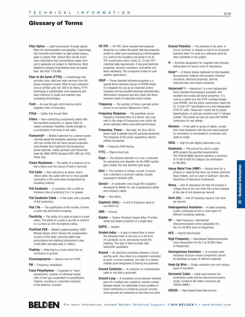
T E C H N I C A L I N F O R M A T I O N 22.29
Glossary of Terms
22 •
Tech
nica
l Inf
orm
atio
n
F o r m o r e i n f o r m a t i o n , c o n t a c t B e l d e n Te c h n i c a l S u p p o r t : 1 - 8 0 0 - B E L D E N - 1 • w w w . b e l d e n . c o m
Fiber Optics — Light transmission through opticalfibers for communication and signaling. A technologythat transmits information as light pulses along aglass or plastic fiber. Optical fiber carries muchmore information than conventional copper wireand is generally not subject to interference. Mosttelephone company long-distance lines are opticalfiber. See RUS 1755.900.
Fiber to the home (FTTH) — A technology that provides voice, data and video services from thephone company’s branch office to local customersover an all-fiber optic link. Still in its infancy, FTTHtechnology is substantially more expensive andlabor-intensive to install and maintain than competing technologies.
Field — An area through which electric and/or magnetic lines of force pass.
Filled — Cables that are gel filled.
Fillers — Non-conducting components cabled with the insulated conductors or optical fibers to impart roundness, flexibility, tensile strength or a combination of all three to the cable.
Flamarrest® — Belden trademark for a plenum gradechloride-based thermoplastic jacketing materialwith low smoke and low flame spread properties;more flexible than traditional fluorocopolymer jacket materials. Cables jacketed with Flamarrestmeet the ANSI/ NFPA Standard 2621-985 (UL-910)Flame Test.
Flame Resistance — The ability of a material not tofuel a flame once the source of heat is removed.
Flat Cable — Also referred to as planar and/or ribbon cable. Any cable with two or more parallelconductors in the same plane encapsulated byinsulating material.
Flat Conductor — A conductor with a width-to-thickness ratio of arbitrarily 5 to 1 or greater.
Flat Conductor Cable — A flat cable with a pluralityof flat conductors.
Flex Life — The qualification of the number of times a cable may bend before breaking.
Flexibility — The ability of a cable to bend in a shortradius. The ability of a cable to lay flat or conformto a surface as with microphone cables.
FlexPoint PCB — Belden’s patent-pending 10GX®
Module design which reduces the compensationcircuitry’s time delay, ensuring stable high performance and enabling transmission rates of 625 MHz and data-rates of 10Gb/s.
Floating — Referring to a circuit which has no connection to ground.
Fluorocopolymer — Generic term for PVDF.
FM — Frequency modulation.
Foam Polyethylene — Expanded or “foam” polyethylene, consists of individual closed cells of inert gas suspended in a polyethylenemedium, resulting in a desirable reduction of the dielectric constant.
FR-TPE — FR-TPE, flame retarded thermoplastic elastomer, is a rubber-like plastic that has propertiessimilar to rubber yet is processed as a thermoplastic.It is used as the insulation and jacket in an all TPE construction which meets UL 13 and 1277industrial cable requirements. It has good electricalproperties, abrasion resistance, colorability andflame retardance. This compound is ideal for coldweather applications.
FREP — Flame retardant ethylene propylene is a special flame retardant version of EPDM rubber. It is designed for use as an industrial control insulation and has excellent electrical characteristics, deformation resistance and also meets the flameretardant needs of industrial control cables.
Frequency — The number of times a periodic actionoccurs in one second. Measured in Hertz.
Frequency Response — The amplitude versus frequency characteristics of a device. Also mayrefer to the range of frequencies over which thedevice operates within prescribed performance.
Frequency, Power — Normally, the 50 or 60 Hzpower used to operate most AC powered equipment.The frequency of AC power supplied by electric utilities companies.
FSK — Frequency Shift Keying.
FTTC — Fiber-to-the-Curb.
Gage — The physical diameter of a wire. A standardfor expressing wire diameter. As the AWG numbergets smaller, the wire diameter gets larger.
Gain — The increase of voltage, current, or powerover a standard or previous reading. Usuallyexpressed in decibels (dB).
Geosol — A solderable, extra tough film insulationdeveloped by Belden for use in geophysical cablesand miniature cables.
Giga — One billion.
Gigahertz (GHz) — A unit of frequency equal to one billion Hz.
GND — Ground.
Gopher — Gopher Resistant Copper Alloy. Providesshield and added protection in a single layer.
GOPIC — Gopher.
Graded-Index — A type of optical fiber in which the refractive index of the core is in the form of a parabolic curve, decreasing toward thecladding. This type of fiber provides high bandwidth capabilities.
Ground — An electrical connection between a circuitand the earth. Also refers to a conductor connectedto earth. In some instances, can refer to a centralmetallic point designated as having zero potential.
Ground Conductor — A conductor in a transmissioncable or line that is grounded.
Ground Loop — A completed circuit between shieldedpairs of a multiple pair created by random contactbetween shields. An undesirable circuit condition inwhich interference is created by ground currentswhen grounds are connected at more than one point.
Ground Potential — The potential of the earth. A circuit, terminal, or chassis is said to be at groundpotential when it is used as a reference point forother potentials in the system.
H — Symbolic designation for magnetic field intensity.Abbreviation for henrys (unit of inductance).
Halar® — A Solvay Solexis trademark for thermoplasticfluoropolymer material with excellent chemicalresistance, electrical properties, thermal characteristics and impact resistance.
Haloarrest® I — Haloarrest I is a non-halogenatedflame retarded thermoplastic polyolefin with excellent low smoke and flame properties. It isused as a jacket over the XLPE insulated singles(non-XHHW), and the entire construction meets theUL 13 and 1277 specifications as a non-halogenatedPLTC/TC cable. Haloarrest I meets the EuropeanSpecifications on acid gas evolution and % Halogencontent. This jacket can also be used with XHHWconductors for wet ratings.
Harness — A flat cable or group of cables, usuallywith many breakouts with the wire ends preparedfor termination or terminated to connectors andready to install.
HDSL — High bit-rate Digital Subscriber Line.
Headroom — The amount by which a cable ACR exceeds the specified requirements. The TIA/EIA-568B standard specifies a minimum of 10 dB of ACR for Category 5e certification at 100 MHz.
Heavy Metal Free (HMF) — General term for aproduct or material that does not contain restrictedheavy metals, such as Lead or Cadmium. See alsoRestriction of Hazardous Substances.
Henry — Unit of inductance (H) that will produce avoltage drop of one volt when the current changesat the rate of one ampere per second.
Hertz (Hz) — Unit of frequency equal to one cycle per second.
Heterogeneous Insulation — A cable insulatingsystem composed of two or more layers of different insulating materials.
HF — High Frequency. InternationalTelecommunication Union designation for the 3 to 30 MHz band of frequencies.
HFC — Hybrid Fiber/Coaxial.
High Frequency — International TelecommunicationUnion designation for the 3 to 30 MHz band of frequencies.
Homogeneous Insulation — A complete cable insulation structure whose components cannot be identified as layers of different materials.
Hook-Up Wire — Single conductor wire with varioustypes of insulation.
Horizontal Cable — Cable used between the workstation outlet and the telecommunicationscloset. Limited to 90 meters maximum per TIA/EIA-568B.1.
HSCDS — High-Speed Cable Data Service.

T E C H N I C A L I N F O R M A T I O N 22.30
Glossary of Terms
F o r m o r e i n f o r m a t i o n , c o n t a c t B e l d e n Te c h n i c a l S u p p o r t : 1 - 8 0 0 - B E L D E N - 1 • w w w . b e l d e n . c o m
HTML — Hypertext Markup Language.
HTTP — Hypertext Transfer Protocol.
Hum — Term used to describe noise in a audio, videoor other system that comes from 60 Hz power orits harmonic(s). So named for the low-frequencyhumming sound produced in audio systems.Usually hum is the result of undesired couplingfrom a 60 Hz source or of inadequate filtering ofthe DC output of an AC input power supply.
Hypalon® — A DuPont trade name for a syntheticrubber (chlorosulfonated polyethylene) used asinsulating and jacketing material for wire and cable.
I — Symbol used to designate current.
I/O Interconnection — Input/Output interface to theoutside world.
I2R — Formula for power in watts, where I = current inamperes, R = resistance in ohms.
ICEA — Insulated Cable Engineers Association.
IDC — Insulation Displacement Connector. Type ofconnector where contact is made to the cable conductor(s) by cutting through the individual conductor’s insulation. The conductor does not need to have its insulation removed prior to connection. Flat cable often uses IDCs to simultaneously connect all conductors.
IDSL — ISDN Digital Subscriber Line.
IEEE — Institute of Electrical and Electronic Engineers.
IETF — Internet Engineering Task Force.
IF — Intermediate Frequency.
IFB — Interrupted Feedback (Foldback). A monitoringscheme often used in television where the feed ofprogram audio to an on-air person can be interruptedwith directions, cues or other information. Usuallyintegrated into the intercom system.
IGMP — Internet Group Management Protocol.
Impedance — The total opposition that a circuitoffers to the flow of alternating current or any other varying current at a particular frequency.
Impedance Match — A condition whereby theimpedance of a particular circuit, cable or componentis the same as the impedance of the circuit, cableor device to which it is connected.
Impedance Matching Stub — A section of transmission line or pair of conductors cut to matchthe impedance of a load. Also called matching stub.
Impedance Matching Transformer — A transformer designed to match the impedance of one circuit to that of another.
Impedance, Characteristic — In a transmissioncable of infinite length, the ratio of the applied voltage to the resultant current at the point the voltage is applied. Or the impedance which makes a transmission cable seem infinitely long, whenconnected across the cable’s output terminals.
Impedance, High — Generally, the area of 25,000 ohms or higher.
Impedance, Low — Generally, the area of 1 through600 ohms.
Index Edge — Reference Edge.
Inductance — The property of wire which stores electrical current in a magnetic field around thewire. By coiling wire, the effect can be intensified. It is measured in Henrys.
Induction — The phenomenon of a voltage, magneticfield or electrostatic charge being produced in anobject from the source of such fields.
Induction Heating — Heating a conducting materialby placing it in a rapidly changing magnetic field.The changing field induces electric currents in thematerial and losses account for the resultant heat.
Inductive Crosstalk — Crosstalk resulting from the coupling of the electromagnetic field of oneconductor upon another.
Injection Laser Diode — Sometimes called thesemiconductor diode. A laser in which the lasingoccurs at the junction of N-type and P-type semiconductor materials.
INMS — Integrated Network Management System.
Input — A signal (or power) which is applied to apiece of electric apparatus or the terminals on theapparatus to which a signal or power is applied.
Insertion Loss — A measure of the attenuation of acable and/or component(s) by determining the output of a system before and after the device isinserted into the system.
Insulation — A material having good dielectric properties which is used to separate close electrical components, such as cable conductorsand circuit components.
Insulation Displacement Connector (IDC) — A mass termination connector for flat cable withcontacts that displace the conductor insulation tocomplete termination.
Insulation Stress — The molecule separation pressure caused by a potential difference across an insulator. The practical stress on insulation isexpressed in volts per mil.
Interface — The region where two systems or a major and a minor system meet and interact with each other.
Interference — Disturbances of an electrical or electromagnetic nature that introduce undesirableresponses into other electronic equipment.
Intermediate Frequency — A frequency to which asignal is converted for ease of handling. Receivesits name from the fact that it is an intermediatestep between the initial and final conversion ordetection stages.
Ionization — The formation of ions. Ions are produced when polar compounds are dissolved in a solvent and when a liquid, gas, or solid is causedto lose or gain electrons due to the passage of anelectric current.
Ionization Voltage — The potential at which a material ionizes. The potential at which an atomgives up an electron.
IP — Internet Protocol.
IPCDN — IP Over Cable Data Network working groupof the IETF.
IR — Insulation Resistance.
IR Drop — The designation of a voltage drop in termsof current and resistance. (See also Voltage Drop.)
IRC — Inter Relay Chat.
IRS — Ignition Radiation Suppression.
Integrated Services Digital Network — An alternative to telephone modems that allows digitaltransmission over ordinary telephone copper wireand other media. Home and business users can gethighly graphic Web pages more quickly throughISDN adapters than through dial-up connections.
ISO — International Standards Organization.
Isolation — The ability of a circuit or component toreject interference, usually expressed in dB.
ISP — Internet Service Provider.
ITFS — Instructional Television Fixed Service.
ITU — International Telecommunications Union.
Jacket — Pertaining to wire and cable, the outer protective covering that may also provide additional insulation.
Jumper — A short length of conductor or flat cableused to make a connection between terminals oraround a break in a circuit or between circuit boards.
kB — Kilobyte.
keV — 1000 electron volts.
Kilo — One thousand.
KPSI — Tensile strength in thousands of pounds per square inch.
kV — Kilovolt (1000 volts).
kVA — Kilo Volt-ampere. One thousand volt-amperes(VA). (See also VA.)
kW — Kilowatt.
L — Symbol for inductance.
Laminated Cable — Insulated or uninsulated wireswhich are encapsulated by two sheets of laminatematerial to maintain a predetermined pitch.
LAN — Local Area Network. A data network connectingany number of users, intended to serve a smallarea. A group of computers and associated devicesthat shares a common communications line and typically shares the resources of a single processor or server within a small geographic area.
Laser — A coherent source of light with a narrowbeam and a narrow spectral bandwidth (about 2nm).
Lay — The length measured along the axis of a wire orcable required for a single strand (in stranded wire)or conductor (in cable) to make one complete turnabout the axis of the conductor or cable. In a twistedpair cable, the lay length is the distance it takes forthe two wires to completely twist around each other.

T E C H N I C A L I N F O R M A T I O N 22.31
Glossary of Terms
22 •
Tech
nica
l Inf
orm
atio
n
F o r m o r e i n f o r m a t i o n , c o n t a c t B e l d e n Te c h n i c a l S u p p o r t : 1 - 8 0 0 - B E L D E N - 1 • w w w . b e l d e n . c o m
Lay Direction — The direction of the progressing spiral twist in a cable while looking along the axis of the cable away from the observer. The lay direction can be either left or right.
Lead Dress — The placement or routing of wiringand component leads in an electrical circuit.
Lead Free — Unless otherwise specified, a homo-geneous material containing less than 300ppm of lead (Pb) which is not intentionally added. See also Heavy Metal Free.
Lead-in — The cable that provides the path for RF energy between the antenna and the receiver or transmitter.
Leakage — The undesirable passage of current overthe surface of or through an insulator.
LEC — Local Exchange Carrier.
Level — A measure of the difference between a quantity or value and an established reference.
LF — Low frequency. International TelecommunicationUnion designation for the 30 to 300 kHz band of frequencies.
Light Emitting Diode (LED Source) — A semiconductor device that emits incoherent lightformed by the P-N junction. Light intensity isroughly proportional to electrical current flow.
Limpness — The ability of a cable to lay flat or conform to a surface as with microphone cables.The ability of a cable to bend in a short radius.
Line Drop — A voltage loss occurring between anytwo points in a power or transmission line. Suchloss or drop is due to the resistance, reactance or leakage of the line. (See also Voltage Drop and IR Drop.)
Line Equalizer — A reactance (inductance and/or capacitance) connected in series with atransmission line to alter the frequency-responsecharacteristics of the line.
Line Level — Refers to the output voltage level of apiece of electronic equipment. Usually expressed in decibels (e.g. 0 dBV).
Line Voltage — The value of the potential existing ona supply or power line.
LMDS — Local Multipoint Distribution Service
Load — A device that consumes power from a sourceand uses that power to perform a function.
Loaded Line — A transmission line that has lumpedelements (inductance or capacitance) added at uni-formly spaced intervals. Loading is used to providea given set of characteristics to a transmission line.
Loading — A transmission line that has lumped elements (inductance or capacitance) added at uniformly spaced intervals. Loading is used to provide a given set of characteristics to a transmission line.
Local Area Network — A data network connectingany number of users, intended to serve a smallarea. (See also LAN.)
Long-wire Antenna — An antenna conductor lengthin excess of one-half of a wavelength.
Loss — Energy or signal lost without accomplishinguseful work.
Lossy — Having high losses resulting in efficiency.
Low Frequency — International TelecommunicationUnion designation for the 30 to 300 kHz band of frequencies.
Luminance Signal — The portion of the compositevideo signal that represents the brightness or theblack and white information.
m — Prefix for milli or one-thousandth.
M — Mutual inductance. The abbreviation for mega or1 million. And also indicates 1000 (one thousand)feet in the wire industry. Lower case m is for millior one-thousandth. (See also m.)
M′ — Notation representing 1000 feet.
mA — milliampere (one-thousandth of an ampere).
MAC — Media Access Control (layer of OSI Reference Model).
MAN — Metropolitan Area Network.
Manufacturing Automation Protocol — A manufacturing automation protocol based on IEEE 802.4 standards.
MAP — Manufacturing Automation Protocol.
Margin — Distance between reference edge of cableand nearest edge of first conductor or center offirst conductor.
Mass-Termination — The process of simultaneouslyterminating all conductors in a single operation.
Matrix IDC™ — Belden’s patent pending 10GX®
Module IDC design which reduces the ANEXTbetween pairs of adjacent modules by 15dB,enabling transmission rates of 625 MHz and data rates of 10Gb/s.
Matte Finish PVC — A special formulation of PVCwhich very closely looks and feels like rubber.
MATV — Abbreviation for Master Antenna Television.
MB — Megabyte.
Mbps — Mega bits per second. The number of bits, in millions, transmitted per second.
MCNS — Multimedia Cable Network System Partners Ltd.
MDS — Multipoint Distribution System.
Mega — Prefix meaning million.
Megahertz (MHz) — Unit of frequency equal to one million Hertz.
Metropolitan Area Network (MAN) — A data network intended to serve the area of a city or an area of similar size.
mfd — Microfarad (one-millionth of a farad). Modern abbreviation is µF (lower case Greek mu followed by F).
Mho — The unit of conductance equal to the reciprocal of the unit of resistance (ohm).
MHz — Megahertz. (See also Megahertz.)
Micro — Prefix meaning one-millionth.
Microfarad — One-millionth of a farad (µf, µfd, mfand mfd are common abbreviations).
Micromicrofarad — One-millionth of a microfarad(µµf, µµfd, mmf, mmfd are common abbreviations).Modern usage is picofarad (pF).
Micron — Millionth of a meter. (µ is a common abbreviation).
Microphonics — Noise caused by mechanical excitation of a system component. In a single-conductor microphone cable, for example, microphonics can be caused by the shield rubbingagainst the dielectric as the cable is flexed.
Mil — A unit of length equal to one thousandth of an inch (.001).
Milli — Prefix meaning one-thousandth.
Mitigation — Strategies or methods to improve Alien Crosstalk performance in the field for 10G transmission over installed-base cabling.
Mode — A single electromagnetic wave traveling in an optical fiber.
Modem — Modulator-Demodulator. Device that converts signals in one form to another form compatible with another kind of equipment.
Modulation — Altering the characteristics of a carrierwave to convey information. Modulation techniquesinclude amplitude frequency, phase, plus manyother forms of on-off digital coding.
Molded Cable — Cable assemblies with molded connectors on one or both ends.
Mono Filament — A single strand filament asopposed to a braided or twisted filament.
MSO — Multiple System Operator. Cable TV termreferring to companies that operate multiple cable TV systems in numerous cities.
MTP — Simple Mail Transfer Protocol.
Multi-Conductor Cable — Cable with more than one conductor.
Multiplex — A technique for putting two or more signals into a single channel.
Mutual Capacitance — Effective capacitance between two conductors when the effects of theother conductors and shield, if present, are removed.
mV — Millivolt (one-thousandth of a volt).
mW — Milliwatt (one-thousandth of a watt).
Mylar® — DuPont trademark for polyethylene terephtalate (polyester) film.
N — Type of coaxial connector named after its inventor,Paul Neil of Bell Labs. Also the symbol for Newton.
Nano — One-billionth.
Nanometer (nm) — One billionth of a meter.
Nanosecond — One billionth of a second.

T E C H N I C A L I N F O R M A T I O N 22.32
Glossary of Terms
F o r m o r e i n f o r m a t i o n , c o n t a c t B e l d e n Te c h n i c a l S u p p o r t : 1 - 8 0 0 - B E L D E N - 1 • w w w . b e l d e n . c o m
NAP — Network Access Point.
National Electrical Code (NEC) — A publication of the National Fire Protection Association (NFPA)which outlines requirements for electrical wiringand building construction.
NBR — Butadiene-acrylonitrile copolymer rubber, amaterial with good oil and chemical resistance.
NEC — National Electrical Code.
NEMA — National Electrical Manufacturers Association.
Neoprene — A synthetic rubber with good resistance tooil, chemical, and flame. Also called polychloroprene.
Network — A method of data communicationsbetween computers.
NEXT — Near-end Crosstalk. Crosstalk induced on the pairs, measured at the end near the transmitter.Usually expressed in decibels (dB).
NFPA — National Fire Protection Association.
Nibble — One half byte (4 bits).
NOC — Network Operations Center.
Noise — In a cable or circuit, any extraneous signalwhich tends to interfere with the signal normallypresent in or passing through the system.
NOMEX® — DuPont trademark for a temperature-resistant, flame-retardant nylon.
Non-Paired Cable — Cable with two or more cabledconductors that are not in a paired configuration.
Non-Plenum — A description for a cable that doesnot meet the requirements of NFPA 262 (UL 910)CMP flame test. Such a cable cannot be installed inan area that is used for air return (plenum).
Notch — The removal of the web section between conductors of a flat cable to aid in stripping, slitting and termination.
NTSC — National Television System Committee.Organization that formulated standards for the current U.S. color television system. This system is used in most countries of the Americas and inother parts of the world. It was designed to becompatible with the existing monochrome TV sets,so that they would not become obsolete. Color televisions would also be able to receive mono-chrome transmissions. NTSC uses a 3.579545 MHzsubcarrier whose phase varies with the instantaneoushue of the televised color and whose amplitudevaries with the instantaneous saturation of thecolor. NTSC employs 525 lines per frame, 29.97frames per second and 59.94 fields per second.
Numerical Aperture (NA) — A measure of theangular acceptance for a fiber. It is approximatelythe sine of the half-angle of the acceptance cone.
Nylon — An abrasion-resistant thermoplastic withgood chemical resistance.
OFDM — Orthogonal Frequency Division Multiplexing.
OFHC — Abbreviation for oxygen-free, high conductivitycopper. It has 99.95% minimum copper contentand an average annealed conductivity of 101%compared to standard copper.
Ohm — The unit of electrical resistance. The value ofresistance through which a potential difference ofone volt will maintain a current of one ampere.
Ohm’s Law — Stated E=IR, I=E/R or R=E/I. The currentI in a circuit is directly proportional to the voltage E,and inversely proportional to the resistance R.
Optical Waveguide Fiber — A transparent filamentof high refractive index core and low refractiveindex cladding that transmits light.
OSI — Open System Interconnect (Model for networking protocols).
OSS — Operations Support Systems.
Output — The useful power or signal delivered by acircuit or device.
Ozone — Extremely reactive form of oxygen, normallyoccurring around electrical discharges and presentin the atmosphere in small but active quantities. In sufficient concentrations it can break down certain rubber insulations under tension (such as a bent cable).
Paired Cable — Cable with conductors cabled ingroups of two.
PAL — Phase Alternation Line. PAL is a European colorTV system featuring 625 lines per frame, 25 framesand 50 fields per second. Used mainly in Europe,China, Malaysia, Australia, New Zealand, the MiddleEast, and parts of Africa. PAL-M is a Brazilian colorTV system with 525 lines per frame, 30 frames and60 fields per second.
Parallel Circuit — A circuit in which the identicalvoltage is presented to all components, with currentdividing among the components according to theresistances or the impedances of the components.
Parallel Digital — Digital information that is transmitted in parallel form. The digits are sent on separate conductors rather than sequentially onone transmission line (serial). Often used informallyto refer to parallel digital television signals.
PASP — Polyethylene Aluminum Steel Polyethylene.Provides additional lightning and gopher protection.
Patchcord — A flexible piece of cable terminated atboth ends with plugs. Used for interconnecting circuits on a patchboard, in a wiring closet or at the work area.
PC — Personal Computer.
PE — Polyethylene.
Peak — The maximum instantaneous value of a varying current or voltage.
Peel Strength — The force necessary to separate two adjacent conductors of a bonded or laminatedflat cable.
Periodicity — The uniformly spaced cable impedancevariations that result in addition of the reflections of a signal. The distance between them is the halfwavelength of the most affected frequency. Multiplesof that frequency are also affected. Even very slight variations, which appear over and over in a construction or installation, can have major effectson signal integrity because of periodicity.
Permanent Link — The horizontal cable including the workstation outlet and patch panel in thetelecommunications closet plus two meters of cable at each end for testing. Limited to a maximum of 90 meters in TIA/EIA-568B.1.
PFA — Perfluoroalkoxy.
Phase — An angular relationship between waves.
Phase Shift — A change in the phase relationshipbetween two alternating quantities.
Photodetector (Receiver) — Converts light energyto electrical energy. The silicon photo diode is most commonly used for relatively fast speeds andgood sensitivity in the .75 micron to .95 micronwavelength region. Avalanche photodiodes (APD)combine the detection of optical signals with internal amplification of photo-current. Internal gain is realized through avalanche multiplication of carriers in the junction region. The advantage in using an APD is its higher signal-to-noise ratio,especially at high bit rates.
PHY — Physical (layer of OSI Reference Model). (See also Physical Layer.)
Physical Layer — The actual portion of a networkthat is used to physically connect computers of a network and over which the data is transmitted— the cable.
PIC — Plastic Insulated Conductor. Provides stronginsulation.
Pickup — Any device which is capable of transforminga measurable quantity of intelligence (such as sound)into relative electrical signals (e.g. a microphone).
Pico — One-trillionth.
Picofarad — One trillionth of a farad. A micromicrofarad. Abbreviated pF in modern usage or mmF in earlier usage.
Pin-diode — A photodetector used to convert optical signals to electrical signals in a receiver. (See also Photodetector.)
Pitch — Nominal distance from center-to-center ofadjacent conductors within a cable. When conductorsare flat, pitch is usually measured from the referenceedge of a conductor to the reference edge of theadjacent conductor. Spacing.
Planar Cable — Also referred to as flat and/or ribbon cable. Any cable with two or more parallelconductors in the same plane encapsulated byinsulating material.
Plastic — High polymeric substances, including both natural and synthetic products that are capable of flowing under heat and pressure, calledthermoplastics. Unlike rubber and other thermosetcompounds, plastics can be remelted and reused.
Plasticizer — A chemical added to plastics to makethem softer and more flexible.
Plenum — A compartment or chamber to which oneor more air ducts are connected and that formspart of the air distribution system. A description fora cable that passes the NFPA 262 (UL-910) CMPflame test requirements.
Plug — A male housing with male or female contacts.

T E C H N I C A L I N F O R M A T I O N 22.33
Glossary of Terms
22 •
Tech
nica
l Inf
orm
atio
n
F o r m o r e i n f o r m a t i o n , c o n t a c t B e l d e n Te c h n i c a l S u p p o r t : 1 - 8 0 0 - B E L D E N - 1 • w w w . b e l d e n . c o m
Point-to-Point Wiring — Wiring that consists ofcontinuous conductors terminated at each end tocircuit destination.
Polarization — The orientation of a flat cable or arectangular connector (e.g. for gray flat cable), thecolored edge indicating the number one conductor.
Polybutadiene — A type of synthetic rubber oftenblended with other synthetic rubbers to improvetheir properties.
Polyethylene (PE) — A thermoplastic material having excellent electrical properties. Low dielectric constant, a stable dielectric constant over all frequencies, very high insulation resistance. Interms of flexibility, polyethylene can be rated stiff to very hard, depending on molecular weight and density — low density being the most flexibleand the high-density, high-molecular weight formulation being very hard. Moisture resistance is rated excellent.
Polymer — A substance made of many repeatingchemical units or molecules. The term polymer isoften used in place of plastic, rubber or elastomer.
Polyolefin — Any of the polymers and copolymers of the ethylene family of hydrocarbons, such aspolyethylene and polypropylene.
Polypropylene (PP) — A thermoplastic similar to polyethylene but stiffer and having a higher softening point (temperature). This material is primarily used as an insulation material. Typically, it is harder than polyethylene. This makes it suitablefor thin wall insulations. The dielectric constant is2.25 for solid and 1.55 for cellular designs.
Polyurethane (PUR) — Broad class of polymersnoted for good abrasion and solvent resistance.Can be in solid or cellular form. This thermoplasticmaterial is used primarily as a cable jacket material.It has excellent oxidation, oil, and ozone resistance.Some formulations also have good flame resistance.It is a hard material with excellent abrasion resistance.It has outstanding memory properties, making it anideal jacket material for retractile cords.
Polyvinyl Chloride (PVC) — A general purpose thermoplastic used for wire and cable insulation and jackets.
Portable Cordage — Cable with two or more twistedconductors for flexible applications. Also calledflexible cord.
POTS — Plain Old Telephone Service. Sometimes used in discussions of new telephone technologiesin which the question of whether and how existingvoice transmission for ordinary telephone communication can be accommodated. For example, DSL and ISDN provide part of their channels for POTS, while using most of their bandwidth for digital data transmission.
Potting — Sealing by filling with a substance toexclude moisture.
Power — The amount of work per unit of time. Usually expressed in watts. Power equals the product of voltage and current (P = V x I).
Power Loss — The difference between the totalpower delivered to a circuit, cable or device and the power delivered by that device to a load.
Power Ratio — The ratio of power appearing at theload to the input power.
PP — Polypropylene.
PPP — Point-to-Point Protocol.
Precision Video — Video coaxial cables having verytight electrical tolerances in impedance, velocity ofpropagation, attenuation and return loss. Used inhigh quality applications such as live broadcast innetwork studios and pre- or post-production facilities.
Premise Cabling — Refers to the entire cabling system used for voice, data, video and power on a user’s premise. For Local Area Networks, thecabling of choice includes unshielded twisted pairs(UTP), fiber optic and coaxial cables. Of these, theUTP market is the largest, with greatest demand forcables with four pairs that meet certain standards ofperformance, such as Category 5 and Category 5e.
PRI — Primary Rate Interface ISDN.
Prop 65 — See California Proposition 65.
Propagation Delay — Time required for a signal topass from the input to the output of a device.
PSAELFEXT — Power sum alien equal level far-endcrosstalk is a computation of the unwanted signalcoupling between pairs in cabling in close proximi-ty from multiple transmit signals at the near-endinto another pair measured at the far-end, and rela-tive to the received signal level.
PSAFEXT — Power sum alien far-end crosstalk loss isa computation of the unwanted signal couplingbetween pairs in cabling in close proximity frommultiple transmit signals at the near-end intoanother pair measured at the far-end.
PSANEXT — Power sum alien near-end crosstalk lossis a computation of the unwanted signal couplingbetween pairs in cabling in close proximity frommultiple transmit signals at the near-end into a pairmeasured at the near-end.
Pseudo Random NRZ — A wave form of binary signals that may be used in a computer system. It is called NRZ, Non-Return to Zero, because thevoltage does not return to zero after each bit.
PSTN — Public Switched Telephone Network.
Pulse — A current or voltage which changes abruptlyfrom one value to another and back to the originalvalue in a finite length of time. Used to describeone particular variation in a series of wave motions.
Put-up — Packaging of finished wire or cable.
PVC — Polyvinyl Chloride. (See also Polyvinyl Chloride.)
PVDF — Polyvinylidene Fluoride.
QAM — Quandrature Amplitude Modulation.
QOS — Quality of Service.
QPSK — Quaternary Phase Shift Keying or Quadrature PSK.
Quad — A four conductor cable. Also called star quad.
R — Symbol for resistance.
Radio Frequency (RF) — Radio Frequency. Includes frequencies from a few kilohertz to severalgigahertz. Used to transmit information from pointto point over the airwaves or cable.
RAM — Random Access Memory.
Rated Temperature — The maximum temperature at which an electric component can operate forextended periods without loss of its basic properties.
Rated Voltage — The maximum voltage at which anelectric component can operate for extended periodswithout undue degradation or safety hazard.
RDC — Regional Data Center.
Reactance — A measure of the combined effects ofcapacitance and inductance on an alternating current.The amount of such opposition varies with the frequency of the current. The reactance of a capacitor decreases with an increase in frequency;the opposite occurs with an inductance.
Receiver — A unit that converts an RF signal toanother type of signal (e.g. radio, television). Alsorefers to an electronic package that converts lightenergy to electrical energy in a fiber optic system.(See also Photodetector.)
Receptacle — A female housing with male or female contacts.
Reference Edge — Edge of cable or conductor fromwhich measurements are made, such as in flat cable.Sometimes indicated by a thread, identification stripeor printing. Conductors are usually identified bytheir sequential position from the reference edge,with number one conductor closest to this edge.
Reflection — The change in direction (or return) of waves striking a surface. For example, electromagnetic energy reflections can occur at an impedance mismatch or variation in a transmission line, causing standing waves.
Reflection Loss — The part of a signal which is lostdue to reflection of power at a line discontinuity.
Refractive Index — The ratio of light velocity in avacuum to its velocity in the transmitting medium.
Registration — Alignment of one object with relation toanother. In flat cables it involves aligning conductorswith contacts or solder pads. Also called register.
Repeater — A receiver and transmitter combinationused to regenerate an attenuated signal.
Resistance — In DC circuits, the opposition a material offers to current flow, measured in ohms.In AC circuits, resistance is the real component ofimpedance, and may be higher than the valuemeasured at DC.
Resonance — An AC circuit condition in which inductive and capacitive reactances interact tocause a minimum or maximum circuit impedance.
T E C H N I C A L I N F O R M A T I O N 22.34
Glossary of Terms
F o r m o r e i n f o r m a t i o n , c o n t a c t B e l d e n Te c h n i c a l S u p p o r t : 1 - 8 0 0 - B E L D E N - 1 • w w w . b e l d e n . c o m
Restricted Flame Retardants — Refers to the EUdirective 2003/11/EC (6-FEB-2003), which bans theuse of Penta- and Octa- BDE compounds. Belden iscurrently using these substances in certain CPEjacket materials only, and plans to phase out usageby January 2006. Contact Belden Customer Serviceor visit www.belden.com for product specific details.
Restriction of Hazardous Substances (RoHS) —Refers to the EU directive 2002/95/EC (27-JAN-2003)which bans the use of certain substances as of July2006. The following items are of primary concernin cables, namely: Asbestos and its compounds,Cadmium and its compounds, Chromium VI and itscompounds, Lead and its compounds, Mercury andits compounds, and Polybrominated Biphenyls(pbbs) and their ethers/oxides (PBDEs, PBBEs).Contact Belden Customer Service or visitwww.belden.com for product specific details.
Retractile Cord — A cord having specially treatedinsulation or jacket so that it will retract like aspring. Retractability may be added to all or part of a cord’s length.
Return Loss — Measure of signal reflections from a cable or device with a fixed, standard referenceimpedance on the measuring equipment. Expressedin decibels (dB).
RF — Radio Frequency.
RFI — Radio Frequency Interference.
RFP — Request for Proposals.
RG/U — RG is the abbreviation for radio guide, a military designation for a coaxial cable, and U stands for universal.
RGB — Abbreviation for the three parts of color video signal: red, green and blue. Also refers tomulti-coaxial cables carrying these signals.
Ribbon Cable — A flat cable made with parallelround conductors in the same plane. Also referredto as planar and/or flat cable. Any cable with two or more parallel conductors in the same planeencapsulated by insulating material.
Ringing Out — The process of locating or identifyingspecific conductor paths by means of passing acurrent through selected conductors.
Riser — The system of pathways that are provided to run riser cables from one floor to another.
RJ-45 — Modular telecommunications connector.
RL — Return Loss.
RMS — Root-mean-square.
Rope Strand — A conductor composed of groups oftwisted strands.
Round Conductor Flat Cable (RCFC) — A cable made with parallel round conductors in the same plane.
Routing — The path followed by a cable or conductor.
RSVP — Resource Reservation Protocol.
RTP — Real-Time Transport Protocol.
Rubber (Wire Insulation) — A general term used to describe wire insulations made of thermosettingelastomers, such as natural or synthetic rubbers,neoprene, Hypalon® butyl rubber and others.
RUS 1755.900 (aka PE90) — A specification forfiber optic cables currently in high demand by thetelecommunications industry. Only a handful ofU.S. manufacturers can produce fiber optic cablesto this specification. Belden is one of them.
S-CDMA — Synchronous Code Division Multiple Access.
S-HDSL — Single-pair High bit-rate Digital Subscriber Line.
SAE — Society of Automotive Engineers.
SBR — A copolymer of styrene and butadiene. AlsoGR-S or Buna-S. Most commonly used type of synthetic rubber.
ScTP — Screened Twisted Pair. Premise network cable with an overall foil shield.
SDI — Serial Digital Interface.
SDSL — Symmetric Digital Subscriber Line.
SEALPIC — Aluminum Shield. Sealed Aluminum.
Self-extinguishing — The characteristic of a materialthat extinguishes its own flame after the ignitingflame is removed.
Self-Support — Undulated core with aluminum, polyethylene and a support strand. For aerial use.
Semiconductor — In wire industry terminology, amaterial possessing electrical conductivity that falls somewhere between that of conductors andinsulators. Usually made by adding carbon particlesto an insulator. Not the same as semiconductormaterials such as silicon, germanium, etc. Used for making transistors and diodes.
Semi-Solid Dielectric — A coaxial design in which amonofilament of plastic holds the center conductor inplace in a hollow plastic tube allowing the remainderof the dielectric to be air. Typical velocities of up to84% can be achieved in this design.
Separator — Pertaining to wire and cable, a layer ofinsulating material such as textile, paper, Mylar®,etc., which is placed between a conductor and itsdielectric, between a cable jacket and the componentsit covers, or between various components of a multiple-conductor cable. It can be utilized toimprove stripping qualities, flexibility or can offeradditional mechanical or electrical protection to the components it separates.
Serial Digital — Digital information that is transmittedin serial form. SDI informally refers to serial digitaltelevision signals that conform to the SMPTE 259Mstandard.
Serial Digital Interface — Informally refers to serialdigital television signals that conform to the SMPTE259M standard.
Series Circuit — A circuit in which the components arearranged end to end to form a single path for current.
Serve Shield — A metallic shield consisting of severalstrands of wire, helically wound and laid parallelaround a cable core in only one direction, asopposed to the two directions with interleaving of a braid shield.
Shannon Capacity — A theoretical calculation of themaximum available data-rate for a channel.
Sheath — Pertaining to wire and cable, the outer protective covering, also called jacket, that mayalso provide additional insulation.
Shield — A tape, serve or braid (usually copper, aluminum or other conductive material) placedaround or between electric circuits or cables or their components, to prevent signal leakage or interference.
Shield Coverage — The optical percentage of a cable actually covered by shielding material.
Shield Effectiveness — The relative ability of ashield to screen out undesirable interference orprevent signal leakage out of the cable. Frequentlyconfused with the term shield coverage.
Shield Percentage — The percentage of physicalarea of a circuit or cable actually covered by shielding material.
Shielded Armored — Types of Shield: Aluminum,Aluminum/Steel and Copper. Cables that requiresome sort of shield.
Signal — Any visible or audible indication which canconvey information. Also, the information conveyedthrough a communication system.
Signal Conductor — A conductor in a transmissioncable or line that carries electrical signals.
Signal to Noise Ratio — Ratio of desired signal toundesired signal (noise) that is often expressed in decibels. Commonly used interchangeably withAttenuation Crosstalk Ratio (ACR) — the differencebetween attenuation and crosstalk, measured in decibels (dB), at a given frequency. Important characteristic in networking transmission to assure that signal sent down a twisted pair isstronger at the receiving end of the cable than are any interference signals imposed on that same pair by crosstalk from other pairs.
Silicone — A material made from silicon and oxygen.Can be in thermosetting elastomer or liquid form.The thermosetting elastomer form is noted for highheat resistance. This is a very soft thermoset insulation. It has excellent electrical properties plusozone resistance, low moisture absorption, weatherresistance, and radiation resistance. It typically haslow mechanical strength and poor scuff resistance.
Single-mode Fiber — An optical fiber wave guide in which only one mode will propagate. The fiberhas a very small core diameter of approximately 8 micro meters. It permits signal transmission atextremely high bandwidths and is generally usedwith laser diodes.
Single-ended — Unbalanced, such as grounding oneside of a circuit or transmission line.
Sinusoidal — Varying in proportion to the sine of anangle or time function. Ordinary alternating currentis sinusoidal.
Hypalon is a DuPont trademark.

T E C H N I C A L I N F O R M A T I O N 22.35
Glossary of Terms
22 •
Tech
nica
l Inf
orm
atio
n
F o r m o r e i n f o r m a t i o n , c o n t a c t B e l d e n Te c h n i c a l S u p p o r t : 1 - 8 0 0 - B E L D E N - 1 • w w w . b e l d e n . c o m
SIS — Single conductor having synthetic thermosettinginsulation of heat-resistant, moisture-resistant,flame-retarding grade. Also made with chemicallycross-linked polyethylene insulation. Used forswitched wiring only.
Skew Rays — A ray that does not intersect the fiberaxis. Generally, a light ray that enters the fiber coreat a very high angle.
Skin Effect — The tendency of alternating current to travel only on the surface of a conductor as itsfrequency increases.
SMA — Subminiature A connector commonly used in VHF, UHF, RF and microwave applications.
SMB — Subminiature B connector snap-mount connector.
SMC — Subminiature C connector.
Snake Cable — A name given to individually shieldedor individually shielded and jacketed, multi-pair audiocables. Used in the connection of multi-channel linelevel audio equipment.
SNMP — Simple Network Management Protocol.
SNR — Signal to Noise Ratio.
SONET — Synchronous Optical Network.
Source — The device from which a signal is markedinto a cable. The device (usually LED or laser) usedto convert an electrical information-carrying signalinto a corresponding optical signal for transmissionby an optical wave guide.
Spacing — The distance between the centers of twoadjacent conductors. Pitch.
Span — The distance between the center of the firstconductor and the center of the last conductor in a flat cable.
Spectral Bandwidth — The difference betweenwavelengths at which the radiant intensity of illumination is half its peak intensity.
Spectrum — Frequencies that exist in a continuousrange and have a common characteristic. A spectrummay be inclusive of many spectrums (e.g. the electromagnetic radiation spectrum includes the lightspectrum, radio spectrum, infrared spectrum, etc.).
Speed of Light (c) — Approximately 2.998 x 10⁸
meters per second.
SpiralFlex™ — Belden’s patent-pending cable designfor the 10GX® Cable which increases randomizationand pair separation, enabling transmission rates of625 MHz and data-rates of 10Gb/s.
Splitter — A device that sends the signal from onesource to two or more receiving devices by allocating a portion of the signal to each receiver(e.g. cable TV splitter). A device that divides a highbandwidth signal into two or more lower bandwidthsignals, each carrying a selected frequency range.Users connected to a DSL line, for example, mayhave a splitter installed at their home or businessto divide the incoming signal into low frequenciesto send to their phone and high frequencies fordata to the computer.
SRL — Structural Return Loss.
Stalpeth (DUCTPIC) — Aluminum steel bonded to thepolyethylene jacket. Helps minimize jacket damage.
Standing Wave — The stationary pattern of waves produced by two waves of the same frequencytraveling in opposite directions on the same transmission line. The existence of voltage and current maxima and minima along a transmissionline is a result of reflected energy from an impedance mismatch.
Standing Wave Ratio (SWR) — A ratio of the maximum amplitude to the minimum amplitude of a standing wave stated in current or voltageamplitudes. (See also Standing Wave.)
Star Quad — Term given to 4-conductor microphonecables where the conductors are spiraled together,which, when connected in an x configuration,greatly increases common mode noise rejection.
Static Charge — An electrical charge that is bound toan object. An unmoving electrical charge.
Stay Cord — A component of a cable, usually of hightensile strength, used to anchor the cable ends at theirpoints of termination and keep any pull on the cablefrom being transferred to the electrical conductors.
Step Insulated — Process of applying insulation intwo layers. Typically used in shielded networkingcables such that the outer layer of insulation can beremoved and remaining conductor and insulationcan be terminated in a RJ-45 type connector.
Step-index Fiber — An optical fiber in which the core is of a uniform refractive index with asharp decrease in the index of refraction at thecore/cladding interface.
STP — Shielded Twisted Pair(s).
Strain Gage — A device for determining the amount of strain (change in dimensions) when a stress is applied.
Strand — A single uninsulated wire.
Stranded Conductor — A conductor composed ofseveral strands or groups of uninsulated wires.
Strip — To remove insulation from a cable or wire.
Stripping Groove — The controlled thinning of thelamination between two conductors in a flat cableto allow easy hand separation. Tear feature.
Structural Return Loss — Magnitude of the internalcable reflections, measured in decibels (dB), relativeto the actual cable impedance, not the systemimpedance. Measure of signal reflections caused by the structure of the cable without the additionalreflections from any impedance mismatch betweenthe cable and the measuring equipment. Measureof internal cable reflections using a referenceimpedance in the measuring equipment that isadjusted to the nominal or average impedance ofthe cable. (See also Return Loss.)
Surge — A temporary and relatively large increase inthe voltage or current in an electric circuit or cable.Also called transient.
S-Video — Transmission method for video in which the two parts of the signal, the chrominance andluminance, are sent on separate transmission lines to provide better picture quality.
Sweep Test — Testing a characteristic of a cable ordevice across a range of frequencies. In cable, itusually implies return loss or structural return loss.(See also Return Loss or Structural Return Loss.)
TCP/IP — Transmission Control Protocol/Internet Protocol.
TDMA — Time Division Multiple Access.
Tear Feature — The controlled thinning of the lamination between two conductors in a flat cable toallow easy hand separation.
Teflon® — DuPont Company trademark for fluorocarbon resins.
Tefzel® — DuPont Company trademark for a ETFE.Fluorocopolymer thermoplastic material which has excellent electrical properties, heat resistance,chemical resistance, toughness, radiation resistance and flame resistance.
Temperature Rating — The maximum temperatureat which the insulating material or cable may beused in continuous operation without change in its basic properties.
Tensile Strength — The pull stress required to breaka bare wire.
TFE — Tetrafluoroethylene. A thermoplastic materialwith good electrical insulating properties andchemical and heat resistance.
Thermal Rating — The temperature range in which a material will perform its function without unduedegradation.
Thermoplastic — A material which will soften, flowor distort appreciably when subjected to sufficientheat and pressure. Examples are polyvinyl chlorideand polyethylene.
Thermoset — A material which will not soften, flow or distort appreciably when subjected to heat and pressure. Vulcanizable. Examples are rubberand neoprene.
TIA — Telecommunications Industry Association. Bodywhich authored the TIA/EIA-568-B CommercialBuilding Telecommunications Wiring Standard inconjunction with EIA.
TIA/EIA-568-B — Commercial BuildingTelecommunications Wiring Standard defines ageneric telecommunications wiring system forcommercial buildings that will support a multi-product, multi-vendor environment. It also providesdirection for the design of telecommunicationsproducts for commercial enterprises.
Tinsel — A type of electrical conductor composed of a number of tiny threads, each thread having a fine,flat ribbon of copper or other metal closely spiraledabout it. Used for small size cables requiring limpness and extra-long flex life.
Topcoated Wire — Conductor produced by applyinga layer of tin over a stranded bare copper conductorholding the strands together allowing easier solderingand preventing the fraying of strands.
TP-PMD — Twisted Pair-Physical Medium Dependent.
T E C H N I C A L I N F O R M A T I O N 22.36
Glossary of Terms
F o r m o r e i n f o r m a t i o n , c o n t a c t B e l d e n Te c h n i c a l S u p p o r t : 1 - 8 0 0 - B E L D E N - 1 • w w w . b e l d e n . c o m
Transducer — A device for converting one form ofenergy to another, such as mechanical energy toelectrical energy.
Transfer Impedance — For a specified cable length,transfer impedance relates to a current on one surface of a shield to the voltage drop generated by this current on the opposite surface of theshield. Transfer impedance is used to determineshield effectiveness against both ingress andegress of interfering signals. Cable shields are normally designed to reduce the transfer ofinterference — hence, shields with lower transferimpedance are more effective than shields withhigher transfer impedance.
Transmission Line — An arrangement of two ormore conductors, such as a coaxial cable or awaveguide used to transfer signal energy from one location to another.
Transmission Line Cable — Two or more conductorsplaced within a dielectric material in such a way asto control the electrical characteristics.
Transmitter — Equipment that generates RF or electrical signals for transmission through the airor space or over a transmissions line. Also refers to the electronic package that converts electricalenergy to light energy in a fiber optic system.
Triad Cable — Cable with three twisted conductors.
Triaxial Cable — A cable construction having a conductor and two isolated braid shields, all insulated from each other. A coaxial cable with a second braid applied over an inner jacket and an outer jacket applied over the outer braid.Commonly used in television camera systems.
Triboelectric Noise — Noise generated in a shieldedcable due to variations in capacitance between theshield and conductors as the cable is flexed.
Trunk Cable — In a CATV system, the transmissioncable from the head end (signal pickup) to thetrunk amplifier. Also called a feeder cable.
Turn-key — A contractual arrangement in which oneparty designs and installs a system and turns overthe keys to another party who will operate the system.
TVRO — TV Receive Only.
Twin-lead — A transmission line having two parallelconductors separated by insulating material. Lineimpedance is determined by the diameter and spacing of the conductors and the insulating material and is usually 300 ohms for televisionreceiving antennas.
Twinax Cable — Cable with two twisted conductorswith established electrical properties (one pair =two conductors sharing a common axis = twinax).
Twisted Pair — Two lengths of insulated conductorstwisted together. The traditional method for connectinghome and many business computers to the telephonecompany. Gets its name because two insulatedcopper wires are twisted together, both of whichare needed for each connection. In commercialenvironments, performance of data transmissioncan be improved by adding a composite tape to the wire. This is known as shielded twisted pair.
Two-pair Premise Wiring — Refers to the two pairsof voice grade (low bandwidth) twisted pair wireinstalled in most homes since the 1950s. The extrapair makes it possible for you to add another linewhen you need it.
UHF — Ultra High Frequency. InternationalTelecommunications Union designation for the 300 to 3000 MHz band of frequencies.
UL — Underwriters Laboratories. A nonprofit organization which tests and verifies constructionand performance of electronic parts and equipment,including wire and cable.
UM — Unsoldered Mechanical Protection. Additionalsteel and polyethylene over inner polyethylene jacket.Provides additional mechanical protection.
Unbalanced Line — A transmission line in whichvoltages on the two conductors are unequal withrespect to ground. A coaxial cable is a commontype of unbalanced line.
Unilay — A conductor with more than one layer ofhelically laid wires with the direction of lay andlength of lay the same for all layers.
UTP — Unshielded Twisted Pair(s).
V — Volt. (See also Volt.)
VA — Volt-ampere. Measure of apparent power in areactive circuit found by multiplying the voltage by the current.
VC/MTM — Variable Constellation/Multi-Tone Modulation.
VDSL — Very high bit rate Digital Subscriber Line.
Velocity of Propagation (VP) — The transmissionspeed of electrical energy in a length of cable compared to speed of light in free space. Usuallyexpressed as a percentage.
VHF — Very High Frequency. InternationalTelecommunications Union designation for the 30 to 300 MHz band of frequencies.
VHS — Abbreviation for Video Home System.
Video — Pertaining to picture information in a television system.
VLF — Very Low Frequency. InternationalTelecommunications Union designation for the 3 to 30 kHz band of frequencies.
Volt — A unit of electromotive force.
Voltage — Electrical potential of electromotive forceexpressed in volts.
Voltage Drop — The voltage developed across acomponent or conductor by the current flowthrough the resistance or impedance of the component or conductor.
Voltage Rating — The highest voltage that may becontinuously applied to a cable construction in conformance with standards or specifications.
Voltage Standing Wave Ratio — Ratio of maximumvoltage of the standing wave to the minimum voltageof the standing wave. (See also Standing Wave Ratio.)
VSWR — Voltage Standing Wave Ratio.
VW-1 — A flammability rating established byUnderwriters Laboratories for wires and cables that pass a specially designed vertical flame test,formerly designed FR-1.
W — Symbol for watt or wattage.
Wall Thickness — The thickness of an insulation or jacket.
WAN — Wide Area Network.
Watt — A unit of electrical power.
Wave Form — A graphical representation of a varyingquantity. Usually, time is represented on the horizontal axis, and the current or voltage value is represented on the vertical axis.
Wavelength — The distance between positive peaksof a signal. As the frequency increases, and wavesget closer together, the wavelength decreases.
WCS — Wireless Communications Service.
Wire — A conductor, either bare or insulated.
Wireless — Really a misnomer. Belden makes a variety of cables needed to build the transmittinginfrastructure required to support wireless devices.Wireless is a technology that allows a device (phone,pager or satellite dish) to be unconnected from the transmission point of a voice, video or data signal. The transmission infrastructure required tosupport such wireless devices is a wired platform oftransmission towers and stations that communicatepoint to point and to telephone central offices.
X — Symbol for reactance.
X-Bar™ — The X-Bar is a plastic device that is used for installing 10GX® Cable onto a 10GX Module,optimizing the termination process and practicallyeliminating performance variation due to termination variances.
XLPE — Crosslinked polyethylene is a thermoset and is crosslinked by radiation, thermally, or bymoisture. XLPE offers a wide range of operatingtemperatures, excellent deformation, abrasion, andflame resistance. XLPE can be formulated withhalogenated or non-halogenated flame retardantpackages. Some grades are also rated XHHW-2which offers excellent wet electrical properties.
XLR — A multi-pin audio connector (typically 3 pins)used in microphone, line level and snake cableaudio connections.
XPE-PVC — Expanded Polyethylene-PolyvinylChloride. Fire retardant.
Z — Symbol for impedance.

IndexPart Numbers
M A S T E R C A T A L O G 23.1
23•
Part
Num
ber I
ndex
1B25A 21.261R25A 21.262L28026 7.42L28034 7.42L28040 7.42L28044 7.42L28050 7.45T00UP 19.37, 20.66, 21.226T00UP 19.37, 20.688R28010 7.88R28014 7.88R28016 7.88R28020 7.88R28025 7.88R28026 7.88R28034 7.88R28037 7.88R28040 7.88R28050 7.88R28060 7.88R28064 7.88V28010 7.108V28014 7.108V28020 7.108V28026 7.108V28036 7.108V28040 7.108V28060 7.109L26010 7.69L26014 7.69L26016 7.69L26020 7.69L26025 7.69L26026 7.69L26034 7.69L26040 7.69L26068 7.69L28009 7.59L28010 7.59L28014 7.59L28015 7.59L28016 7.59L28020 7.59L28024 7.59L28025 7.59L28026 7.59L28034 7.59L28036 7.59L28037 7.59L28040 7.59L28050 7.59L28060 7.59L28064 7.59L28309 7.119L28310 7.119L28315 7.119L28320 7.119L28325 7.119L28326 7.119L28334 7.119L28337 7.119L28340 7.119L28350 7.119L28360 7.119L30026 7.39L30050 7.39R28010 7.79R28014 7.79R28016 7.79R28020 7.79R28024 7.79R28025 7.79R28026 7.79R28034 7.79R28037 7.79R28040 7.79R28050 7.7
9R28060 7.79R28064 7.79V28010 7.99V28014 7.99V28016 7.99V28020 7.99V28026 7.99V28034 7.99V28036 7.99V28040 7.99V28050 7.99V28060 7.99V28064 7.99V28310 7.129V28314 7.129V28326 7.129V28334 7.129V28350 7.12179DT 19.50, 19.78500PTZ 20.42501PTZ 20.44502PTZ 20.46538AFS 20.36540BUE 20.9600PTZ 20.43601PTZ 20.45602PTZ 20.47638AFS 20.35658AFS 20.35720A 6.58734A1 6.56734A12 6.56734A1P 6.56, 6.58734A6 6.56734D1 6.57734D12 6.57734D1P 6.57734D1T 6.57734D2 6.57734D2T 6.57734D6 6.57735A1 6.55735A12 6.55735A16 6.55735A1P 6.55735A1T 6.55735A2 6.55735A24 6.55735A3 6.55735A6 6.55735A8 6.55735A9 6.55735O2T 6.551000A 18.541006A 18.541012A 18.541013A 18.541014A 18.541018A 18.541023A 18.541030A 18.491031A 18.501032A 18.471033A 18.441034A 18.501035A 18.491036A 18.481037A 18.591038A 18.571039A 18.591040A 18.591041A 18.591042A 18.591043A 18.591044A 18.591045A 18.591046A 18.59
1047A 18.591048A 18.571049A 18.571050A 18.571051A 18.571052A 18.571053A 18.571054A 18.571055A 18.591056A 18.441057A 18.441058A 18.441059A 18.441060A 18.441061A 18.441062A 18.441063A 18.571064A 18.571065A 18.571066A 18.571067A 18.571068A 18.571069A 18.591070A 18.591071A 18.591072A 18.591073A 18.591074A 18.591075A 18.441076A 18.441077A 18.441078A 18.441079A 18.441080A 18.441081A 18.441082A 18.441083A 18.451084A 18.451085A 18.451086A 18.451087A 18.571088A 18.571089A 18.591090A 18.591091A 18.441092A 18.451093A 18.581094A 18.581095A 18.581096A 18.581097A 18.601098A 18.601099A 18.601100A 18.601101A 18.541114A 18.551115A 18.551116A 18.551117A 18.551118A 18.591119A 18.601120A 18.571121A 18.581151A 6.181152A 6.251153A 6.281164B 19.701167B 6.48, 19.701172A 19.81186A 6.171189A 6.24, 21.131189AP 6.24, 21.131190A 6.251191AM 6.241192A 19.81211A 4.211212A 4.21
1213A 4.211214A 4.211215A 15.801217B 19.221218B 19.221219B 19.221220B 19.221221B 19.221222B 19.221225B 19.221226B 19.221227A1 15.631229A1 15.631232A1 15.631242A 4.31243A2 15.631245A2 15.631258AM 6.191260AM 6.231263B 19.681266A 5.19, 19.101268A 5.331269A 5.33, 5.521277P 6.48, 19.711277R 6.48, 19.71, 21.161278P 6.48, 19.711278R 6.48, 19.71, 21.161279P 6.48, 19.711279R 6.48, 19.71, 21.161280P 6.48, 19.711280R 6.48, 19.71, 21.161281R 6.34, 19.41, 19.711281S3 6.49, 19.72, 21.171281S4 6.49, 19.72, 21.171281S5 6.49, 19.72, 21.171281S6 6.49, 19.72, 21.171282P 6.34
19.41, 19.71, 21.161282S3 6.49, 19.72, 21.171282S4 6.49, 19.72, 21.171282S5 6.49, 19.72, 21.171282S6 6.49, 19.72, 21.171283S3 6.46
19.56, 19.73, 21.181283S5 6.46
19.56, 19.73, 21.181283S6 6.46
19.56, 19.73, 21.181300A 19.761300SB 15.67, 19.761304A 19.761305A 19.761306SB 6.39, 20.381307A 19.36, 21.201308A 19.36, 21.201309A 19.36, 21.201310A 19.36, 21.201311A 19.36, 21.201312A 19.36, 21.201313A 19.36, 21.201322R 6.241401A 15.821403A 15.821406B 6.47, 19.691407B 6.47, 19.691408R 19.181409R 19.181410R 19.181411R 19.181412R 19.181413R 19.181414R 19.181415R 19.181416R 19.181417B 6.47, 19.691418B 6.48, 19.701419A 5.15
1420A 5.151421A 5.151422A 5.151423A 5.151424A 5.151425A 5.151426A 6.37, 19.461427B 19.221428B 19.221466A 18.471467A 18.471468A 18.471471A 18.471472A 18.471474A 18.471475A 18.471476A 18.471477A 18.471480A 18.471481A 18.471484A 18.491485A 18.491486A 18.491489A 18.491490A 18.491492A 18.491493A 18.491494A 18.491495A 18.491498A 18.491499A 18.491500A 15.54, 20.40, 20.531500R 15.54
20.40, 20.53, 21.101501A 15.54, 20.41, 20.541502P 19.391502R 19.39, 21.81503A 5.19, 19.101504A 5.20, 19.131505A 6.29, 6.42, 21.141505F 6.29, 6.42, 19.521506A 6.42, 19.52 1508A 5.16, 19.91509C 19.191510C 19.191511C 19.191512C 19.191513C 19.191514C 19.191515C 19.191516C 19.191517C 19.191518C 19.191519C 19.191520A 6.47, 19.691521A 6.47, 19.691522A 6.47, 19.691523A 6.261523AN 6.261523AP 6.261523R 6.261524AM 6.261525A 6.261526A 18.451527A 18.591528A 18.491529A 18.471530A 6.201530AP 6.201531AM 6.201532A 6.201533P 15.671533R 15.671538A 15.811540A 15.811545A 6.191546A 6.21
F o r m o r e i n f o r m a t i o n , c o n t a c t B e l d e n Te c h n i c a l S u p p o r t : 1 - 8 0 0 - B E L D E N - 1 • w w w . b e l d e n . c o m
Part No. Page Part No. Page Part No. Page Part No. Page Part No. Page
How To Use This Index: All part numbers beginning with a number are listed in numerical sequence; any alpha characters within the part number are ignored for sequencing purposes. All part numbers beginning with an alpha character follow behind the numerical listings in an alpha/numeric sequence. Also use the e-catalog on www.belden.com for part number searches.
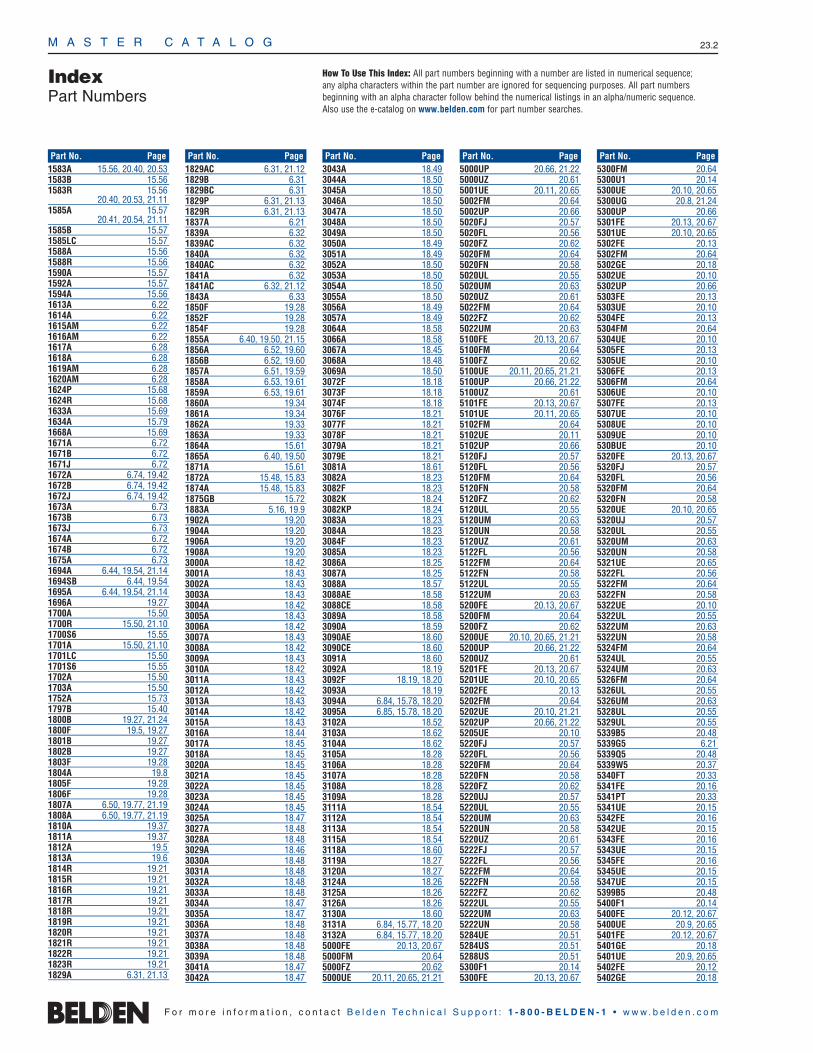
M A S T E R C A T A L O G 23.2
IndexPart Numbers
1583A 15.56, 20.40, 20.531583B 15.561583R 15.56
20.40, 20.53, 21.111585A 15.57
20.41, 20.54, 21.111585B 15.571585LC 15.571588A 15.561588R 15.561590A 15.571592A 15.571594A 15.561613A 6.221614A 6.221615AM 6.221616AM 6.221617A 6.281618A 6.281619AM 6.281620AM 6.281624P 15.681624R 15.681633A 15.691634A 15.791668A 15.691671A 6.721671B 6.721671J 6.721672A 6.74, 19.421672B 6.74, 19.421672J 6.74, 19.421673A 6.731673B 6.731673J 6.731674A 6.721674B 6.721675A 6.731694A 6.44, 19.54, 21.141694SB 6.44, 19.541695A 6.44, 19.54, 21.141696A 19.271700A 15.501700R 15.50, 21.101700S6 15.551701A 15.50, 21.101701LC 15.501701S6 15.551702A 15.501703A 15.501752A 15.731797B 15.401800B 19.27, 21.241800F 19.5, 19.271801B 19.271802B 19.271803F 19.281804A 19.81805F 19.281806F 19.281807A 6.50, 19.77, 21.191808A 6.50, 19.77, 21.191810A 19.371811A 19.371812A 19.51813A 19.61814R 19.211815R 19.211816R 19.211817R 19.211818R 19.211819R 19.211820R 19.211821R 19.211822R 19.211823R 19.211829A 6.31, 21.13
1829AC 6.31, 21.121829B 6.311829BC 6.311829P 6.31, 21.131829R 6.31, 21.131837A 6.211839A 6.321839AC 6.321840A 6.321840AC 6.321841A 6.321841AC 6.32, 21.121843A 6.331850F 19.281852F 19.281854F 19.281855A 6.40, 19.50, 21.15 1856A 6.52, 19.601856B 6.52, 19.601857A 6.51, 19.591858A 6.53, 19.611859A 6.53, 19.611860A 19.341861A 19.341862A 19.331863A 19.331864A 15.611865A 6.40, 19.50 1871A 15.611872A 15.48, 15.831874A 15.48, 15.831875GB 15.721883A 5.16, 19.91902A 19.201904A 19.201906A 19.201908A 19.203000A 18.423001A 18.433002A 18.433003A 18.433004A 18.423005A 18.433006A 18.423007A 18.433008A 18.423009A 18.433010A 18.423011A 18.433012A 18.423013A 18.433014A 18.423015A 18.433016A 18.443017A 18.453018A 18.453020A 18.453021A 18.453022A 18.453023A 18.453024A 18.453025A 18.473027A 18.483028A 18.483029A 18.463030A 18.483031A 18.483032A 18.483033A 18.483034A 18.473035A 18.473036A 18.483037A 18.483038A 18.483039A 18.483041A 18.473042A 18.47
3043A 18.493044A 18.503045A 18.503046A 18.503047A 18.503048A 18.503049A 18.503050A 18.493051A 18.493052A 18.503053A 18.503054A 18.503055A 18.503056A 18.493057A 18.493064A 18.583066A 18.583067A 18.453068A 18.483069A 18.503072F 18.183073F 18.183074F 18.183076F 18.213077F 18.213078F 18.213079A 18.213079E 18.213081A 18.613082A 18.233082F 18.233082K 18.243082KP 18.243083A 18.233084A 18.233084F 18.233085A 18.233086A 18.253087A 18.253088A 18.573088AE 18.583088CE 18.583089A 18.583090A 18.593090AE 18.603090CE 18.603091A 18.603092A 18.193092F 18.19, 18.203093A 18.193094A 6.84, 15.78, 18.203095A 6.85, 15.78, 18.203102A 18.523103A 18.623104A 18.623105A 18.283106A 18.283107A 18.283108A 18.283109A 18.283111A 18.543112A 18.543113A 18.543115A 18.543118A 18.603119A 18.273120A 18.273124A 18.263125A 18.263126A 18.263130A 18.603131A 6.84, 15.77, 18.203132A 6.84, 15.77, 18.205000FE 20.13, 20.675000FM 20.645000FZ 20.625000UE 20.11, 20.65, 21.21
5000UP 20.66, 21.225000UZ 20.615001UE 20.11, 20.655002FM 20.645002UP 20.665020FJ 20.575020FL 20.565020FZ 20.625020FM 20.645020FN 20.585020UL 20.555020UM 20.635020UZ 20.615022FM 20.645022FZ 20.625022UM 20.635100FE 20.13, 20.675100FM 20.645100FZ 20.625100UE 20.11, 20.65, 21.215100UP 20.66, 21.225100UZ 20.615101FE 20.13, 20.675101UE 20.11, 20.655102FM 20.645102UE 20.115102UP 20.665120FJ 20.575120FL 20.565120FM 20.645120FN 20.585120FZ 20.625120UL 20.555120UM 20.635120UN 20.585120UZ 20.615122FL 20.565122FM 20.645122FN 20.585122UL 20.555122UM 20.635200FE 20.13, 20.675200FM 20.645200FZ 20.625200UE 20.10, 20.65, 21.215200UP 20.66, 21.225200UZ 20.615201FE 20.13, 20.675201UE 20.10, 20.655202FE 20.135202FM 20.645202UE 20.10, 21.215202UP 20.66, 21.225205UE 20.105220FJ 20.575220FL 20.565220FM 20.645220FN 20.585220FZ 20.625220UJ 20.575220UL 20.555220UM 20.635220UN 20.585220UZ 20.615222FJ 20.575222FL 20.565222FM 20.645222FN 20.585222FZ 20.625222UL 20.555222UM 20.635222UN 20.585284UE 20.515284US 20.515288US 20.515300F1 20.145300FE 20.13, 20.67
5300FM 20.645300U1 20.145300UE 20.10, 20.655300UG 20.8, 21.245300UP 20.665301FE 20.13, 20.675301UE 20.10, 20.655302FE 20.135302FM 20.645302GE 20.185302UE 20.105302UP 20.665303FE 20.135303UE 20.105304FE 20.135304FM 20.645304UE 20.105305FE 20.135305UE 20.105306FE 20.135306FM 20.645306UE 20.105307FE 20.135307UE 20.105308UE 20.105309UE 20.10530BUE 20.105320FE 20.13, 20.675320FJ 20.575320FL 20.565320FM 20.645320FN 20.585320UE 20.10, 20.655320UJ 20.575320UL 20.555320UM 20.635320UN 20.585321UE 20.655322FL 20.565322FM 20.645322FN 20.585322UE 20.105322UL 20.555322UM 20.635322UN 20.585324FM 20.645324UL 20.555324UM 20.635326FM 20.645326UL 20.555326UM 20.635328UL 20.555329UL 20.555339B5 20.485339G5 6.215339Q5 20.485339W5 20.375340FT 20.335341FE 20.165341PT 20.335341UE 20.155342FE 20.165342UE 20.155343FE 20.165343UE 20.155345FE 20.165345UE 20.155347UE 20.155399B5 20.485400F1 20.145400FE 20.12, 20.675400UE 20.9, 20.655401FE 20.12, 20.675401GE 20.185401UE 20.9, 20.655402FE 20.125402GE 20.18
F o r m o r e i n f o r m a t i o n , c o n t a c t B e l d e n Te c h n i c a l S u p p o r t : 1 - 8 0 0 - B E L D E N - 1 • w w w . b e l d e n . c o m
Part No. Page Part No. Page Part No. Page Part No. Page Part No. Page
How To Use This Index: All part numbers beginning with a number are listed in numerical sequence; any alpha characters within the part number are ignored for sequencing purposes. All part numbers beginning with an alpha character follow behind the numerical listings in an alpha/numeric sequence. Also use the e-catalog on www.belden.com for part number searches.

IndexPart Numbers
M A S T E R C A T A L O G 23.3
23•
Part
Num
ber I
ndex
5402UE 20.95403FE 20.125403UE 20.95405FE 20.125405UE 20.95406UE 20.95407FE 20.125407UE 20.95408UE 20.95409UE 20.95421FE 20.675439W5 20.375540FT 20.335441FE 20.165442FE 20.165445FE 20.165500F1 20.145500FE 20.12, 20.675500UE 20.9, 20.655500UG 20.8, 21.245501FE 20.12, 20.675501G1 20.195501GE 20.185501UE 20.9, 20.655502FE 20.125502G1 20.195502GE 20.185502UE 20.95502UG 20.8, 21.245503FE 20.125503UE 20.95504FE 20.125504G1 20.195504UE 20.95506FE 20.125506UE 20.95508FE 20.125508UE 20.95509UE 20.95520FE 20.12, 20.675520UE 20.9, 20.655520UG 20.8, 20.285521FE 20.12, 20.675521G1 20.195522FL 20.565522G1 20.195522UE 20.95522UG 20.8, 20.285522UL 20.555524UE 20.95524UL 20.555526UE 20.95529UE 20.95540FT 20.335541FE 20.165541PT 20.335541UE 20.155542FE 20.165542GE 20.185542UE 20.155543FE 20.165543PE 20.175543UE 20.155545FE 20.165547UE 20.155561FE 20.165562FE 20.165563FE 20.16558AFS 20.365582UE 20.95582UG 20.85600FE 20.12, 20.675624UG 20.28, 20.715626UG 20.28, 20.715660FT 20.335661PT 20.335662UG 20.28, 20.71
6000FE 20.24, 20.696000UE 20.22, 20.686001UE 20.22, 20.686002UE 20.226020FL 20.596020UL 20.596051 18.916054 18.916059 18.916060 18.916100FE 20.24, 20.696100UE 20.22, 20.68, 21.216101FE 20.24, 20.696101UE 20.22, 20.686102UE 20.226120FL 20.596120UJ 20.606120UL 20.596122FL 20.596122UL 20.596139B8 20.496157 18.946163 18.946164 18.946179 18.946193 18.946200FE 20.24, 20.696200UE 20.21, 20.68, 21.216201FE 20.24, 20.696201UE 20.21, 20.686202FE 20.246202UE 20.216220FK 20.606220FL 20.596220UJ 20.606220UL 20.596222FL 20.596222UL 20.596284UE 20.526284US 20.526288US 20.526300FC 20.30, 20.706300FE 20.24, 20.696300UE 20.21, 20.686301FE 20.24, 20.696301UE 20.21, 20.686302FC 20.30, 20.706302FE 20.246302UE 20.216303UE 20.216304FE 20.246304UE 20.216306FE 20.246306UE 20.216307FE 20.246307UE 20.216308UE 20.216309FE 20.246309UE 20.216320FE 20.24, 20.696320FK 20.606320FL 20.596320UE 20.21, 20.686320UJ 20.606320UL 20.596321UE 20.21, 20.686321UL 20.596322FL 20.596322UE 20.216322UL 20.596324UL 20.596326UL 20.596328UL 20.596339Q8 20.496340FT 20.346341PC 20.326341PT 20.34
6341UE 20.256342FE 20.266342PC 20.326342UE 20.256343FE 20.266343PC 20.326343UE 20.256345FE 20.266345PC 20.326345UE 20.256347FE 20.266347UE 20.256400FC 20.30, 20.706400FE 20.23, 20.696400UE 20.20, 20.686401FE 20.23, 20.696401GE 20.276401UE 20.686402FE 20.236402UE 20.206403UE 20.206405FE 20.236406UE 20.206407FE 20.236420FE 20.23, 20.696439C8 20.496439Q8 20.496441FE 20.266443FE 20.266500FC 20.30, 20.706500FE 20.23, 20.696500UE 20.20, 20.686501FE 20.23, 20.696501GE 20.276501UE 20.20, 20.686502FC 20.30, 20.706502FE 20.236502GE 20.276502UE 20.206504FE 20.236504UE 20.206506FE 20.236506UE 20.206508FE 20.236508UE 20.206509UE 20.206520FE 20.23, 20.696520UE 20.20, 20.686521FE 20.23, 20.696521UE 20.20, 20.686522UE 20.206522UL 20.596524UE 20.206524UL 20.596539Y8 20.396540FT 20.346541FE 20.266541PA 19.25, 20.326541PT 20.346541UE 20.256542FE 20.266542PA 19.25, 20.326542UE 20.256543FE 20.266543PA 19.25, 20.326543UE 20.256545FE 20.266545PA 19.25, 20.326545UE 20.256546PA 19.25, 20.326547FE 20.266547UE 20.256548PA 19.25, 20.326549PA 19.25, 20.326561FE 20.266561UE 20.256624UG 20.29, 20.72
6626UG 20.29, 20.726641FC 20.316660FT 20.346661PT 20.346662UG 20.29, 20.727101A 18.327102A 18.327105A 18.327106A 18.327106AS 18.327107A 18.327108A 18.327110A 18.327111AS 18.327113A 18.327115A 18.327115AS 18.327116A 18.327117A 18.327122A 18.337123AS 18.337125A 18.337126A 18.337127A 18.337128A 18.337129A 18.337136A 18.337136AS 18.337145A 18.337200A 18.397201A 18.397202A 18.397203A 18.397205A 18.397206A 18.6, 18.397400A 18.347401A 18.347401AS 18.347402A 18.347402AS 18.347403A 18.347403AS 18.347404A 18.347404AS 18.347405A 18.347406A 18.347407A 18.347408A 18.347409A 18.357410A 18.357411A 18.357411AS 18.357412A 18.357413A 18.357413AS 18.357414A 18.357415A 18.357415AS 18.357416A 18.357416AS 18.357417A 18.357417AS 18.357418A 18.357419A 18.357420A 18.357421A 18.367422A 18.367423A 18.367423AS 18.367424A 18.367425A 18.367426A 18.367427A 18.367427AS 18.367428A 18.367428AS 18.367429A 18.36
7430A 18.367434A 18.377435A 18.377436A 18.377436AS 18.377438A 18.377438AS 18.377439A 18.377440A 18.377442A 18.377444A 18.377445A 18.377445AS 18.377447A 18.387447AS 18.387450A 18.387450AS 18.387453A 18.387500A 18.407501A 18.407502A 18.407503A 18.407504A 18.407700A 6.50, 19.77, 21.197710A 6.46, 19.56 7711A 6.46, 19.567712A 6.46, 19.567713A 6.46, 19.56, 21.147731A 6.44, 19.54 7732A 6.44, 19.54, 19.587733A 6.707787A 6.45, 19.557788A 6.45, 19.557789A 6.45, 19.557790A 6.45, 19.557791A 6.45, 19.557792A 6.45, 19.557794A 6.45, 19.557795A 6.45, 19.557796A 6.45, 19.557798A 6.45, 19.557803A 6.54, 19.627804C 19.647804R 19.647805 6.59, 6.667805R 6.59, 6.667806A 6.60, 6.667806R 6.607807A 6.60, 6.667807R 6.607808A 6.61, 6.667808R 6.617808WB 6.617809A 6.627809R 6.627809WB 6.627810A 6.63, 6.667810R 6.637810WB 6.637813LC 15.537851A 15.467851NH 15.467852A 15.467855A 19.787876A 21.57876S 21.37877A 21.57878A 21.67878S 21.37880A 19.287881A 15.52
20.40, 20.53, 21.97882A 15.52
20.41, 20.54, 21.97883A 15.727884A 19.177885A 19.17
F o r m o r e i n f o r m a t i o n , c o n t a c t B e l d e n Te c h n i c a l S u p p o r t : 1 - 8 0 0 - B E L D E N - 1 • w w w . b e l d e n . c o m
Part No. Page Part No. Page Part No. Page Part No. Page Part No. Page
How To Use This Index: All part numbers beginning with a number are listed in numerical sequence; any alpha characters within the part number are ignored for sequencing purposes. All part numbers beginning with an alpha character follow behind the numerical listings in an alpha/numeric sequence. Also use the e-catalog on www.belden.com for part number searches.

M A S T E R C A T A L O G 23.4
IndexPart Numbers
7886A 19.177887A 19.177888A 19.177889A 19.177890A 19.287891A 19.287892A 19.287893A 19.287895A 18.247896A 18.227897A 18.227900A 18.227910A 21.57911A 21.77912A 21.77913A 21.67913S 21.47914A 21.67914S 21.47915A 6.33, 21.127916A 6.33, 21.127916AP 21.127917A 21.77918A 18.107919A 18.107921A 18.97922A 18.97923A 18.87924A 18.97927A 18.117928A 18.87929A 18.97930A 18.107931A 18.117932A 18.87933A 18.97934A 18.87949A 21.87950A 21.87951A 21.87952A 21.87956S 21.47976A 6.647976R 6.647976WB 6.647977A 6.657977R 6.657977WB 6.657983A 6.277984A 6.277985LC 20.7, 20.507986LC 20.7, 20.507987P 19.747987R 19.747988P 15.71, 19.757988R 15.71, 19.757989P 15.70, 19.757989R 15.70, 19.757997A 15.568000 3.278002 3.278011 3.278012 3.278013 3.278018 3.278019 3.278020 3.278021 3.278022 3.278023 3.278024 3.278025 3.278049 3.258050 3.258051 3.258052 3.258053 3.25
8054 3.258055 3.258056 3.258057 3.258058 3.258073 3.258074 3.258075 3.258076 3.258077 3.258078 3.258079 3.258080 3.258081 3.258083 3.258085 3.258102 5.318103 5.318104 5.318105 5.318106 5.318107 5.318108 5.318110 5.318112 5.31, 19.578115 5.318118 5.318125 5.318132 5.278132FO 5.148133 5.278133FO 5.148134 5.278134FO 5.148135 5.278135FO 5.148138 5.278138FO 5.148142 5.27, 19.578142FO 5.148148 5.278148FO 5.148155 5.278155FO 5.148162 5.448163 5.448164 5.448165 5.448166 5.448167 5.448168 5.458170 5.458175 5.458178 5.458185 5.458205 5.7, 19.358208 5.238212 6.37, 19.468213 6.39, 19.488214 6.698215 6.38, 19.478216 6.678218 6.34, 19.418219 6.688221 6.36, 19.448232 6.51, 19.598232A 6.51, 19.598233 6.54, 19.628233A 6.54, 19.628237 6.698238 6.39, 19.488240 6.688241 6.35, 19.438241A 6.35. 19.438241B 6.35, 19.43, 21.158241F 6.35, 19.438254 6.85
8255 6.858259 6.688261 6.39, 19.488262 6.778263 6.36, 19.448267 6.788268 6.788279 6.41, 19.518281 6.30, 6.43, 19.538281B 6.30, 6.43, 19.538281F 6.30, 6.43, 19.528286 19.678302 5.328303 5.328304 5.328305 5.328306 5.328307 5.328308 5.328310 5.328312 5.328315 5.328318 5.328325 5.328332 5.298333 5.298334 5.298335 5.298336 5.298337 5.298340 5.298342 5.298345 5.298348 5.298355 5.298402 19.68403 19.78404 19.88405 19.408406 19.78407 19.88408 19.68410 19.48412 19.68413 19.58416 19.388417 19.388418 19.408421 19.388422 19.68423 19.78424 19.88425 19.408426 19.408427 19.408428 19.68434 5.468437 5.238441 5.238442 4.3, 19.358443 4.38444 4.38445 4.38446 4.78448 4.88450 5.18, 19.108451 5.19, 19.108452 9.58453 9.88454 9.98455 9.98456 4.38457 4.48458 4.48459 4.48460 19.338461 5.7, 19.35
8465 4.58466 4.58467 4.58468 4.58469 4.58470 19.338471 5.9, 19.358472 9.48473 5.9, 19.358477 5.9, 19.358478 9.48479 9.68484 4.88486 5.78489 4.58500 3.78501 3.78502 3.78503 3.78504 3.78505 3.78520 3.78521 3.78522 3.78523 3.78524 3.78525 3.78527 3.78529 3.78530 3.78538 3.78597 3.78618 4.138619 4.68620 4.68621 4.68622 4.68623 4.68624 4.68627 4.78628 4.78629 4.78641 5.16, 19.98643 4.148649 19.328660 3.268661 3.268662 3.268663 3.268668 3.268669 3.268670 3.268673 4.88675 4.88677 4.88678 4.88690 5.88691 5.88692 5.88700 6.828718 5.22, 19.158719 5.22, 19.158720 5.22, 19.158722 5.478723 5.38, 18.29,
19.12, 21.248723SB 5.38, 19.128724 5.468725 5.478728 5.468729 4.128730 5.468732 5.238734 4.148735 4.148737 5.24, 19.118740 5.4
8741 5.48742 5.48743 5.48744 5.48747 5.58748 5.58749 5.58750 5.58751 5.178752 5.188757 5.48759 5.24, 19.138760 5.21, 18.29, 19.148761 5.18, 19.118762 5.20, 19.138763 5.478764 5.378765 5.378766 5.378767 5.378768 5.378769 5.40, 19.238770 4.138771 4.128772 4.128773 5.40, 19.238774 5.40, 19.238775 5.40, 19.238776 5.40, 19.238777 5.40, 18.29, 19.238777SB 5.40, 19.128778 5.40, 19.238780 5.24, 19.158782 19.328786 4.208787 4.208788 4.208790 5.24, 19.148791 4.148794 4.38795 4.38816 3.88824 3.88825 3.88866 3.228868 3.228869 3.228888 9.38890 3.248897 3.238898 3.248899 3.238908 3.68910 3.58915 3.58916 3.58917 3.58918 3.58919 3.58920 3.59011 6.269058 6.239059M 6.239062 6.239064 6.279065M 6.279066 6.199077 6.199100 6.16, 19.469104 6.179104N 6.179104P 6.179105M 6.179110 6.179116 6.19, 21.139116P 6.199116R 6.19
F o r m o r e i n f o r m a t i o n , c o n t a c t B e l d e n Te c h n i c a l S u p p o r t : 1 - 8 0 0 - B E L D E N - 1 • w w w . b e l d e n . c o m
Part No. Page Part No. Page Part No. Page Part No. Page Part No. Page
How To Use This Index: All part numbers beginning with a number are listed in numerical sequence; any alpha characters within the part number are ignored for sequencing purposes. All part numbers beginning with an alpha character follow behind the numerical listings in an alpha/numeric sequence. Also use the e-catalog on www.belden.com for part number searches.
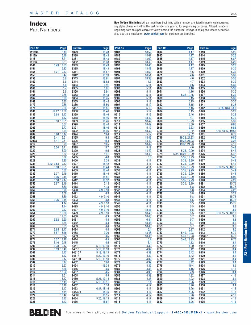
IndexPart Numbers
M A S T E R C A T A L O G 23.5
23•
Part
Num
ber I
ndex
9116SB 6.199117M 6.199118 6.219119M 6.219141 6.43, 19.539151 19.339154 5.21, 19.139155 5.479156 5.89157 5.89159 5.89160 5.49161 5.89165 19.659167 6.299169 6.809170 19.669171 19.669180 19.27, 19.589182 6.88, 18.179184 5.179192 6.53, 19.619201 6.679203 6.779204 6.799207 6.88, 18.179209 6.41, 19.519209A 6.41, 19.519212 6.799221 6.34, 19.419222 6.909223 6.829224 6.829228 6.859231 6.42, 6.58, 19.539232 6.53, 19.619239 6.829240 6.37, 19.469244 6.36, 19.449248 6.38, 19.479250 6.87, 18.169251 6.699252 6.769254 19.689258 6.699259 6.36, 19.459260 4.149261 4.149262 19.679264 19.389265 19.659267 6.52, 19.609268 6.859269 6.859271 6.88, 18.179272 6.87, 18.169273 6.779274 6.37, 19.469275 6.16, 19.469290 6.38, 19.479292 6.39, 19.489302 5.179305 5.179306 5.179309 5.179310 6.679311 6.689312 18.529314 18.519315 5.179316 18.499318 18.469319 5.179320 18.449322 18.429327 5.179328 18.43
9329 18.439330 18.439331 18.439332 18.439333 18.439335 18.439341 18.579342 18.599343 18.619344 18.629354 6.919355 6.919356 6.919363 18.439364 18.459365 18.489366 18.509367 18.519368 18.469369 18.469388 18.469389 18.469390 18.469391 18.469392 18.469394 19.49395 19.49396 19.49397 19.59398 19.79399 19.59402 5.419405 4.89406 5.389407 18.429408 18.449409 18.469410 18.499411 18.519412 18.529414 5.189418 4.139420 4.9, 9.109421 4.39422 4.9, 9.109423 4.39424 4.9, 9.109425 4.9, 9.109427 4.9, 9.109429 4.9, 9.109430 4.39431 4.49432 4.49433 4.49434 4.49438 3.269439 4.59444 4.59445 4.59451 5.19, 19.109451D 5.19, 19.139451DP 5.19, 19.139451P 5.20, 19.109451SB 5.19, 19.109452 19.69454 19.389455 4.59457 4.59458 4.59460 5.21, 19.149461 5.18, 19.119462 5.189463 6.87, 18.159463DB 18.159463F 18.159464 5.20, 19.139486 18.57
9487 18.599488 18.619489 18.629491 18.439492 18.459493 18.489494 18.509495 18.519497 19.339498 4.69501 5.119502 5.119503 5.119504 5.119505 5.119506 5.129507 5.129508 5.129509 5.129510 5.129512 18.429513 18.429514 18.429515 5.129516 18.429519 5.129520 18.429521 18.429524 18.429525 5.129526 18.429527 18.429531 3.89533 4.119534 4.119535 4.119536 4.119537 4.119538 4.119539 4.119540 4.119541 4.119542 4.119543 4.119544 4.119545 4.119546 4.119550 5.129552 18.469553 18.469554 18.469555 6.849556 18.469559 18.469562 5.49563 18.469565 18.469566 5.49570 5.49571 4.329572 4.329574 4.329575 4.329576 4.329578 4.329579 4.329580 4.339581 4.339582 4.339583 4.339585 5.49608 4.179609 4.179610 4.179611 4.179612 4.179613 4.17
9614 4.179615 4.179616 4.179617 4.179618 4.179619 4.179620 4.69621 4.69622 4.69623 4.79626 4.69637 4.169641 4.169659 6.36, 19.459680 5.159681 5.159682 5.159683 5.159684 5.159685 5.469686 4.79688 15.799689 15.809696 5.339708 19.329712 19.329716 19.32, 21.239717 19.32, 21.239718 19.32, 21.239721 4.69728 5.35, 19.299729 5.35, 18.29, 19.299730 5.35, 19.299731 5.35, 19.299732 5.35, 19.299733 5.35, 19.299734 5.35, 19.299735 5.35, 19.299736 5.35, 19.299737 5.35, 19.299738 5.35, 19.299740 5.89741 5.89742 5.89743 5.89744 5.59745 5.59746 5.59747 5.59748 5.59750 5.79751 5.79752 5.79755 5.79764 6.279767 5.40, 19.239768 5.40, 19.239769 5.40, 19.239770 4.129772 4.209773 5.429774 5.429775 5.429776 5.429777 5.429778 19.49791 4.169794 4.39802 4.229803 4.229804 5.269805 5.269806 5.269807 5.269808 5.269809 5.269812 5.26
9813 5.269814 5.269815 6.879819 5.269825 5.269829 5.309830 5.309831 5.309832 5.309833 5.309834 5.309835 5.309836 5.309837 5.309838 5.309839 5.309841 5.289842 5.28, 18.3, 18.59843 5.289844 5.289850 6.799855 5.339857 6.809859 6.819860 6.88, 18.17, 19.589861 6.789862 6.809867 3.229868 4.109873 5.429874 5.429875 5.429876 5.429877 5.429879 5.429880 6.83, 15.74, 18.139883 5.419886 5.419888 6.909890 4.229891 15.769892 15.769894 4.229899 3.239901 15.759902 15.759903 15.759904 3.69906 3.69907 6.83, 15.74, 18.139908 3.69909 3.39910 3.59911 3.39912 3.59913 6.709913F7 6.709914 6.709916 3.49917 3.39918 3.49919 3.49920 3.49921 3.49923 3.49924 3.59925 4.189926 3.49927 4.189928 3.49929 4.189930 3.49931 4.189932 4.189933 4.189934 4.189935 4.18
F o r m o r e i n f o r m a t i o n , c o n t a c t B e l d e n Te c h n i c a l S u p p o r t : 1 - 8 0 0 - B E L D E N - 1 • w w w . b e l d e n . c o m
Part No. Page Part No. Page Part No. Page Part No. Page Part No. Page
How To Use This Index: All part numbers beginning with a number are listed in numerical sequence; any alpha characters within the part number are ignored for sequencing purposes. All part numbers beginning with an alpha character follow behind the numerical listings in an alpha/numeric sequence. Also use the e-catalog on www.belden.com for part number searches.

M A S T E R C A T A L O G 23.6
IndexPart Numbers
9936 4.189937 4.189938 4.189939 4.199940 4.199941 4.199942 4.199943 4.199944 4.199945 4.199946 4.199947 4.199948 4.199949 4.199950 4.199951 4.159952 4.159953 4.159954 4.159961 4.159962 4.159963 4.159964 4.159965 4.159966 4.159967 4.159968 4.159975 3.39976 3.39977 3.39978 3.39979 3.39980 3.39981 3.39982 3.39983 3.39984 3.39985 3.39986 3.39987 3.39989 3.49990 5.379991 5.379992 5.379993 5.379995 5.379998 9.711700A 18.811700A2 18.811872A 18.1119105 9.619106 9.619107 9.619108 9.619109 9.619115 9.31912A 19.2019120 9.519122 9.319123 9.319124 9.619125 9.619126 9.319129 9.619130 9.619140 9.51916A 19.2019201 9.419202 9.419203 9.419204 9.419205 9.619206 9.619207 9.619208 9.619209 9.619216 9.9
19217 9.919227 9.419228 9.419229 9.719230 9.71924A 19.201932A 19.2019348 9.719349 9.719350 9.819352 9.719353 9.719354 9.719362 9.719363 9.719364 9.719401 9.919402 9.819403 9.919404 9.319405 9.319500 9.519501 9.519502 9.519503 9.819504 9.819505 9.819506 9.419507 9.419508 9.419509 9.819510 9.819511 9.821100 18.7721101 18.7721102 18.7721103 18.7721104 18.7721105 18.7721106 18.7721107 18.7721108 18.7721109 18.7721110 18.7721111 18.7721112 18.7721113 18.7721114 18.7721115 18.7721116 18.7721117 18.7721118 18.7721119 18.7721120 18.7721121 18.7721122 18.7721123 18.7721124 18.7721125 18.7721126 18.7721127 18.7721128 18.7721129 18.7721130 18.7721131 18.7721132 18.7721133 18.7721134 18.7721135 18.7721136 18.7721137 18.7721138 18.7721139 18.7721140 18.7721141 18.7721142 18.7721143 18.77
21144 18.7721145 18.7721146 18.7721147 18.7721148 18.7721149 18.7721150 18.7721151 18.7721152 18.7721153 18.7721154 18.7721155 18.7721156 18.7721157 18.7721158 18.7721159 18.7721160 18.7721161 18.7721162 18.7721163 18.7721164 18.7721165 18.7721166 18.7721167 18.7721168 18.7721169 18.7721170 18.7721171 18.7721172 18.7721173 18.7721174 18.7721175 18.7721176 18.7721177 18.7721178 18.7721179 18.7721180 18.7721181 18.7721182 18.7721183 18.7721184 18.7721185 18.7721186 18.7721187 18.7721188 18.7721189 18.7721190 18.7721191 18.7721192 18.7721193 18.7721194 18.7721195 18.7721196 18.7721197 18.7721198 18.7721199 18.7721200 18.7721201 18.7721202 18.7721203 18.7721204 18.7721205 18.7721206 18.7721207 18.7721208 18.7721209 18.7721210 18.7721211 18.7721212 18.7721213 18.7721214 18.7721215 18.7721216 18.7721217 18.7721218 18.7721219 18.7721220 18.77
21221 18.7721222 18.7721223 18.7721224 18.7721225 18.7721226 18.7721227 18.7721228 18.7721229 18.7721230 18.7721231 18.7721232 18.7721233 18.7721234 18.7721235 18.7721236 18.7721237 18.7721238 18.7721239 18.7721240 18.7721241 18.7721242 18.7721243 18.7721244 18.7721245 18.7721246 18.7721247 18.7721248 18.7721249 18.7721250 18.7721251 18.7721252 18.7721253 18.7721254 18.7721255 18.7721256 18.7721257 18.7721258 18.7721259 18.7721260 18.7721261 18.7721262 18.7721263 18.7721264 18.7721265 18.7721266 18.7721267 18.7721300 18.8421301 18.8421302 18.8421303 18.8421304 18.8421305 18.8421306 18.8421307 18.8421308 18.8421309 18.8421310 18.8421311 18.8421312 18.8421313 18.8421314 18.8421315 18.8421316 18.8421317 18.8421318 18.8421319 18.8421320 18.8421321 18.8421322 18.8421323 18.8421324 18.8421325 18.8421326 18.8421327 18.8421328 18.8421329 18.84
21330 18.8421331 18.8421332 18.8421333 18.8421334 18.8421335 18.8421336 18.8421337 18.8421338 18.8421339 18.8421340 18.8421341 18.8421342 18.8421343 18.8421344 18.8421345 18.8421346 18.8421347 18.8421348 18.8421350 18.8421351 18.8421352 18.8421353 18.8421354 18.8421355 18.8421356 18.8421357 18.8421358 18.8421359 18.8421360 18.8421361 18.8421362 18.8421363 18.8421364 18.8421365 18.8421366 18.8421367 18.8421368 18.8421369 18.8421370 18.8421371 18.8421372 18.8421373 18.8421374 18.8421375 18.8421376 18.8421377 18.8421378 18.8421379 18.8421380 18.8421381 18.8421382 18.8421383 18.8421384 18.8421385 18.8421386 18.8421387 18.8421388 18.8421389 18.8421390 18.8421391 18.8421392 18.8421393 18.8421394 18.8421395 18.8421396 18.8421397 18.8421398 18.8421400 18.8421401 18.8421402 18.8421403 18.8421404 18.8421405 18.8421406 18.8421407 18.8421408 18.84
F o r m o r e i n f o r m a t i o n , c o n t a c t B e l d e n Te c h n i c a l S u p p o r t : 1 - 8 0 0 - B E L D E N - 1 • w w w . b e l d e n . c o m
Part No. Page Part No. Page Part No. Page Part No. Page Part No. Page
How To Use This Index: All part numbers beginning with a number are listed in numerical sequence; any alpha characters within the part number are ignored for sequencing purposes. All part numbers beginning with an alpha character follow behind the numerical listings in an alpha/numeric sequence. Also use the e-catalog on www.belden.com for part number searches.
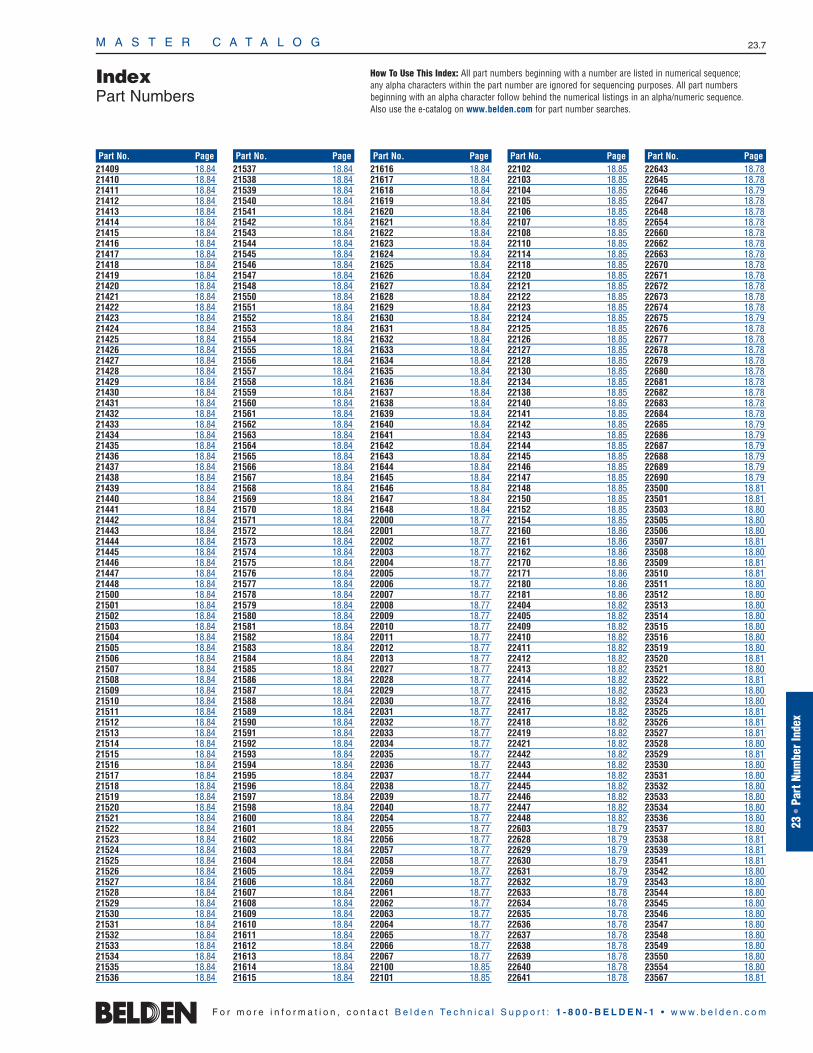
IndexPart Numbers
M A S T E R C A T A L O G 23.7
23•
Part
Num
ber I
ndex
21409 18.8421410 18.8421411 18.8421412 18.8421413 18.8421414 18.8421415 18.8421416 18.8421417 18.8421418 18.8421419 18.8421420 18.8421421 18.8421422 18.8421423 18.8421424 18.8421425 18.8421426 18.8421427 18.8421428 18.8421429 18.8421430 18.8421431 18.8421432 18.8421433 18.8421434 18.8421435 18.8421436 18.8421437 18.8421438 18.8421439 18.8421440 18.8421441 18.8421442 18.8421443 18.8421444 18.8421445 18.8421446 18.8421447 18.8421448 18.8421500 18.8421501 18.8421502 18.8421503 18.8421504 18.8421505 18.8421506 18.8421507 18.8421508 18.8421509 18.8421510 18.8421511 18.8421512 18.8421513 18.8421514 18.8421515 18.8421516 18.8421517 18.8421518 18.8421519 18.8421520 18.8421521 18.8421522 18.8421523 18.8421524 18.8421525 18.8421526 18.8421527 18.8421528 18.8421529 18.8421530 18.8421531 18.8421532 18.8421533 18.8421534 18.8421535 18.8421536 18.84
21537 18.8421538 18.8421539 18.8421540 18.8421541 18.8421542 18.8421543 18.8421544 18.8421545 18.8421546 18.8421547 18.8421548 18.8421550 18.8421551 18.8421552 18.8421553 18.8421554 18.8421555 18.8421556 18.8421557 18.8421558 18.8421559 18.8421560 18.8421561 18.8421562 18.8421563 18.8421564 18.8421565 18.8421566 18.8421567 18.8421568 18.8421569 18.8421570 18.8421571 18.8421572 18.8421573 18.8421574 18.8421575 18.8421576 18.8421577 18.8421578 18.8421579 18.8421580 18.8421581 18.8421582 18.8421583 18.8421584 18.8421585 18.8421586 18.8421587 18.8421588 18.8421589 18.8421590 18.8421591 18.8421592 18.8421593 18.8421594 18.8421595 18.8421596 18.8421597 18.8421598 18.8421600 18.8421601 18.8421602 18.8421603 18.8421604 18.8421605 18.8421606 18.8421607 18.8421608 18.8421609 18.8421610 18.8421611 18.8421612 18.8421613 18.8421614 18.8421615 18.84
21616 18.8421617 18.8421618 18.8421619 18.8421620 18.8421621 18.8421622 18.8421623 18.8421624 18.8421625 18.8421626 18.8421627 18.8421628 18.8421629 18.8421630 18.8421631 18.8421632 18.8421633 18.8421634 18.8421635 18.8421636 18.8421637 18.8421638 18.8421639 18.8421640 18.8421641 18.8421642 18.8421643 18.8421644 18.8421645 18.8421646 18.8421647 18.8421648 18.8422000 18.7722001 18.7722002 18.7722003 18.7722004 18.7722005 18.7722006 18.7722007 18.7722008 18.7722009 18.7722010 18.7722011 18.7722012 18.7722013 18.7722027 18.7722028 18.7722029 18.7722030 18.7722031 18.7722032 18.7722033 18.7722034 18.7722035 18.7722036 18.7722037 18.7722038 18.7722039 18.7722040 18.7722054 18.7722055 18.7722056 18.7722057 18.7722058 18.7722059 18.7722060 18.7722061 18.7722062 18.7722063 18.7722064 18.7722065 18.7722066 18.7722067 18.7722100 18.8522101 18.85
22102 18.8522103 18.8522104 18.8522105 18.8522106 18.8522107 18.8522108 18.8522110 18.8522114 18.8522118 18.8522120 18.8522121 18.8522122 18.8522123 18.8522124 18.8522125 18.8522126 18.8522127 18.8522128 18.8522130 18.8522134 18.8522138 18.8522140 18.8522141 18.8522142 18.8522143 18.8522144 18.8522145 18.8522146 18.8522147 18.8522148 18.8522150 18.8522152 18.8522154 18.8522160 18.8622161 18.8622162 18.8622170 18.8622171 18.8622180 18.8622181 18.8622404 18.8222405 18.8222409 18.8222410 18.8222411 18.8222412 18.8222413 18.8222414 18.8222415 18.8222416 18.8222417 18.8222418 18.8222419 18.8222421 18.8222442 18.8222443 18.8222444 18.8222445 18.8222446 18.8222447 18.8222448 18.8222603 18.7922628 18.7922629 18.7922630 18.7922631 18.7922632 18.7922633 18.7822634 18.7822635 18.7822636 18.7822637 18.7822638 18.7822639 18.7822640 18.7822641 18.78
22643 18.7822645 18.7822646 18.7922647 18.7822648 18.7822654 18.7822660 18.7822662 18.7822663 18.7822670 18.7822671 18.7822672 18.7822673 18.7822674 18.7822675 18.7922676 18.7822677 18.7822678 18.7822679 18.7822680 18.7822681 18.7822682 18.7822683 18.7822684 18.7822685 18.7922686 18.7922687 18.7922688 18.7922689 18.7922690 18.7923500 18.8123501 18.8123503 18.8023505 18.8023506 18.8023507 18.8123508 18.8023509 18.8123510 18.8123511 18.8023512 18.8023513 18.8023514 18.8023515 18.8023516 18.8023519 18.8023520 18.8123521 18.8023522 18.8123523 18.8023524 18.8023525 18.8123526 18.8123527 18.8123528 18.8023529 18.8123530 18.8023531 18.8023532 18.8023533 18.8023534 18.8023536 18.8023537 18.8023538 18.8123539 18.8123541 18.8123542 18.8023543 18.8023544 18.8023545 18.8023546 18.8023547 18.8023548 18.8023549 18.8023550 18.8023554 18.8023567 18.81
F o r m o r e i n f o r m a t i o n , c o n t a c t B e l d e n Te c h n i c a l S u p p o r t : 1 - 8 0 0 - B E L D E N - 1 • w w w . b e l d e n . c o m
Part No. Page Part No. Page Part No. Page Part No. Page Part No. Page
How To Use This Index: All part numbers beginning with a number are listed in numerical sequence; any alpha characters within the part number are ignored for sequencing purposes. All part numbers beginning with an alpha character follow behind the numerical listings in an alpha/numeric sequence. Also use the e-catalog on www.belden.com for part number searches.

M A S T E R C A T A L O G 23.8
IndexPart Numbers
23568 18.8123571 18.8023575 18.8023578 18.8124500 18.8324501 18.8324502 18.8324503 18.8324504 18.8324505 18.8324506 18.8324507 18.8324508 18.8324509 18.8324510 18.8324511 18.8324512 18.8324513 18.8324514 18.8324515 18.8324516 18.8324517 18.8324518 18.8324519 18.8324520 18.8325500 18.8325501 18.8325502 18.8325503 18.8325504 18.8325505 18.8325506 18.8325507 18.8325508 18.8325509 18.8325510 18.8325511 18.8325512 18.8325513 18.8325514 18.8325517 18.8325518 18.8325519 18.8325520 18.8325522 18.8325523 18.8326500 18.8126501 18.8126502 18.8126503 18.8126504 18.8126505 18.8126506 18.8126507 18.8126508 18.8126509 18.8126510 18.8126511 18.8126512 18.8126513 18.8126514 18.8026515 18.8026516 18.8026517 18.8026518 18.8026519 18.8026520 18.8026521 18.8026522 18.8026523 18.8026524 18.8026525 18.8026526 18.8026527 18.8026528 18.8026529 18.8026530 18.80
26531 18.8026532 18.8026533 18.8026534 18.8026535 18.8026536 18.8026537 18.8026538 18.8026539 18.8026540 18.8026541 18.8026542 18.8026543 18.8026544 18.8026545 18.8126546 18.8026547 18.8126551 18.8126553 18.8026555 18.8027080A 18.6627081A 18.6627081AS 18.6627082A 18.6627082AS 18.6627083A 18.6627084A 18.6627085A 18.6627086A 18.6627087A 18.6627088A 18.6627089A 18.6627090A 18.6627091A 18.6627092A 18.6627093A 18.6627094A 18.6627095A 18.6627096A 18.6627097A 18.6627098A 18.6627099A 18.6627100A 18.6627101A 18.6627102A 18.6627103A 18.6627104A 18.6627105A 18.6627106A 18.6627107A 18.6627108A 18.6627109A 18.6727110A 18.6727111A 18.6727112A 18.6727113A 18.6727114A 18.6727115A 18.6727116A 18.6727117A 18.6727118A 18.6727119A 18.6727120A 18.6727121A 18.6727122A 18.6727123A 18.6727124A 18.6727125A 18.6727126A 18.6727127A 18.6727128A 18.6727129A 18.6727130A 18.6727131A 18.6727132A 18.6727133A 18.6727134A 18.67
27135A 18.6727136A 18.6727137A 18.6727138A 18.6827139A 18.6827140A 18.6827141A 18.6827142A 18.6827143A 18.6827144A 18.6827145A 18.6827146A 18.6827147A 18.6827148A 18.6827149A 18.6827150A 18.6827151A 18.6827152A 18.6827153A 18.6827154A 18.6827155A 18.6927156A 18.6927157A 18.6927158A 18.6927159A 18.6927160A 18.6927161A 18.6927243 18.7127244 18.7127245 18.7127246 18.7127247 18.7127248 18.7127249 18.7127250 18.7127251 18.7127252 18.7127253 18.7127254 18.7127255 18.7127256 18.7127257 18.7227258 18.7227259 18.7227260 18.7227261 18.7227262 18.7227263 18.7227264 18.7327265 18.7327267 18.7327268 18.7327269 18.7127270 18.7127271 18.7127272 18.7127273 18.7127274 18.7127275 18.7127276 18.7127277 18.7127278 18.7127279 18.7127280 18.7127281 18.7227282 18.7227283 18.7227284 18.7227285 18.7227286 18.7227287 18.7227288 18.7227289 18.7227290 18.7227291 18.7227292 18.7127293 18.72
27323A 18.6527324A 18.6527325A 18.6427325AS 18.6427326A 18.6427326AS 18.6427327A 18.6427328A 18.6427329A 18.6427330A 18.6527331A 18.6527331AS 18.6527334A 18.6427334AS 18.6427335A 18.6427336A 18.6427337A 18.6527337AS 18.6527338A 18.6527339A 18.6527340A 18.6527341A 18.6527428 18.7327429 18.7327430 18.7327431 18.7327432 18.7127433 18.7127434 18.7127535 18.7127538 18.7127539 18.7127540 18.7127541 18.7227600A 18.6427601A 18.6427602A 18.6427603A 18.6427604A 18.6427605A 18.6427606A 18.6427607A 18.6427608A 18.6427609A 18.6427610A 18.6427611A 18.6427612A 18.6427613A 18.6427614A 18.6427615A 18.6527616A 18.6527617A 18.6527618A 18.6527619A 18.6527620A 18.6527621A 18.6527622A 18.6527623A 18.6527624A 18.6527625A 18.6527626A 18.6527627A 18.6527628A 18.6527629A 18.6627630A 18.6727632A 18.6427633A 18.6527634A 18.6727636A 18.6627641A 18.6727643A 18.6827840 18.7427841 18.7427842 18.7427843 18.7427844 18.7427845 18.74
27846 18.7427847 18.7427848 18.7427849 18.7427850 18.7427851 18.7427852 18.7427853 18.7427854 18.7427855 18.7427856 18.7427857 18.7427858 18.7427859 18.7427860 18.7427861 18.7427862 18.7427863 18.7427864 18.7427865 18.7427866 18.7527867 18.7527868 18.7527869 18.7527870 18.7527871 18.7527872 18.7527873 18.7527874 18.7527875 18.7527876 18.7527877 18.7527878 18.7527879 18.7527880 18.7527881 18.7527882 18.7527883 18.7527884 18.7527885 18.7427886 18.7427887 18.7427888 18.7627889 18.7627890 18.7627891 18.7627892 18.7627893 18.7627894 18.7527895 18.7527896 18.7527912A 18.6627916A 18.6427917A 18.6527969 18.7128243 18.7128244 18.7128245 18.7128246 18.7128247 18.7128248 18.7128249 18.7128250 18.7128251 18.7128252 18.7128253 18.7128254 18.7128255 18.7128256 18.7128257 18.7228258 18.7228259 18.7228260 18.7228261 18.7228262 18.7228263 18.7228264 18.73
F o r m o r e i n f o r m a t i o n , c o n t a c t B e l d e n Te c h n i c a l S u p p o r t : 1 - 8 0 0 - B E L D E N - 1 • w w w . b e l d e n . c o m
Part No. Page Part No. Page Part No. Page Part No. Page Part No. Page
How To Use This Index: All part numbers beginning with a number are listed in numerical sequence; any alpha characters within the part number are ignored for sequencing purposes. All part numbers beginning with an alpha character follow behind the numerical listings in an alpha/numeric sequence. Also use the e-catalog on www.belden.com for part number searches.
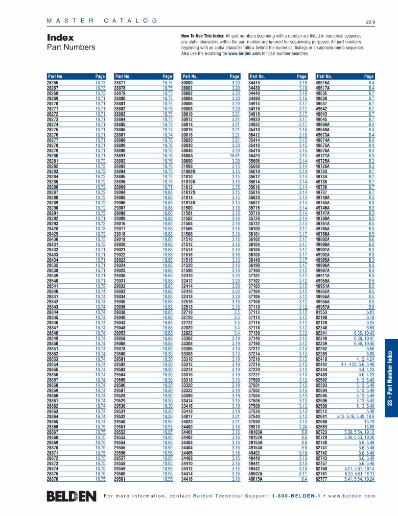
IndexPart Numbers
M A S T E R C A T A L O G 23.9
23•
Part
Num
ber I
ndex
28265 18.7328267 18.7328268 18.7328269 18.7128270 18.7128271 18.7128272 18.7128273 18.7128274 18.7128275 18.7128276 18.7128277 18.7128278 18.7128279 18.7128280 18.7128281 18.7228282 18.7228283 18.7228284 18.7228285 18.7228286 18.7228287 18.7228288 18.7228289 18.7228290 18.7228291 18.7228292 18.7128293 18.7228428 18.7328429 18.7328430 18.7328431 18.7328432 18.7128433 18.7128434 18.7128535 18.7128538 18.7128539 18.7128540 18.7128541 18.7228840 18.7428841 18.7428842 18.7428843 18.7428844 18.7428845 18.7428846 18.7428847 18.7428848 18.7428849 18.7428850 18.7428851 18.7428852 18.7428853 18.7428854 18.7428855 18.7428856 18.7428857 18.7428858 18.7428859 18.7428860 18.7428861 18.7428862 18.7428863 18.7428864 18.7428865 18.7428866 18.7528867 18.7528868 18.7528869 18.7528870 18.7528871 18.7528872 18.7528873 18.7528874 18.7528875 18.7528876 18.75
28877 18.7528878 18.7528879 18.7528880 18.7528881 18.7528882 18.7528883 18.7528884 18.7528885 18.7428886 18.7428887 18.7428888 18.7628889 18.7628890 18.7628891 18.7628892 18.7628893 18.7628894 18.7528895 18.7528896 18.7528969 18.7129004 18.8829005 18.8829006 18.8829007 18.8829008 18.8829009 18.8829016 18.8829017 18.8829018 18.8829019 18.8829020 18.8829021 18.8829022 18.8829023 18.8829024 18.8829025 18.8829030 18.8829031 18.8829032 18.8829033 18.8829034 18.8829035 18.8829036 18.8829038 18.8829040 18.8829043 18.8829048 18.8829053 18.8829058 18.8829068 18.8829078 18.8829500 18.3029501 18.3029502 18.3029503 18.3029504 18.3029505 18.3029506 18.3029507 18.3029528 18.3029529 18.3029530 18.3029531 18.3029532 18.3029550 18.9529551 18.9529552 18.9529553 18.9529554 18.9529555 18.9529556 18.9529557 18.9529558 18.9529559 18.9529560 18.9529561 18.95
30800 3.2030801 3.2030802 3.2030804 3.2030806 3.2030808 3.2030810 3.2130812 3.2130814 3.2130816 3.2130818 3.2130820 3.2130830 3.2030840 3.203080A 18.6130890 3.2031008 3.1531008N 3.1531010 3.1531010N 3.1531012 3.1531012N 3.1531014 3.1531014N 3.1531500 3.1831501 3.1831502 3.1831504 3.1831506 3.1831508 3.1831510 3.1831512 3.1831514 3.1831516 3.1831518 3.1831520 3.1831590 3.1832410 3.2032412 3.2032414 3.2032416 3.2032418 3.2032516 3.1832518 3.1832718 3.532720 3.532722 3.532820 3.432822 3.433302 3.1933304 3.1933306 3.1933308 3.1933310 3.1933312 3.1933314 3.1933316 3.1933318 3.1933320 3.1933322 3.1933390 3.1933414 3.1933416 3.1933418 3.1934017 3.2134020 3.2134400 3.1634401 3.1634402 3.1634403 3.1634404 3.1634406 3.1634408 3.1634410 3.1634412 3.1634414 3.1634416 3.16
34418 3.1634430 3.1634440 3.1634490 3.1634914 3.1734916 3.1734918 3.1734920 3.1734922 3.1735410 3.1535412 3.1535414 3.1535416 3.1535418 3.1535420 3.1535606 3.1435608 3.1435610 3.1435612 3.1435614 3.1435616 3.1435618 3.1435620 3.1435622 3.1435716 3.1435718 3.1435720 3.1435722 3.1436100 3.1736101 3.1736102 3.1736104 3.1736106 3.1736108 3.1736140 3.1736190 3.1737100 3.1237101 3.1237102 3.1237103 3.1237104 3.1237106 3.1237108 3.1237110 3.1237112 3.1237114 3.1237116 3.1237118 3.1237130 3.1237140 3.1237190 3.1237212 3.1337214 3.1337216 3.1337218 3.1337220 3.1337222 3.1337500 3.1337501 3.1337502 3.1337504 3.1337506 3.1337508 3.1337530 3.1337540 3.1337590 3.1339018 3.2449103A 8.949152A 8.849153A 8.849154A 8.849402 8.1049440 8.1049441 8.1049442 8.1049502A 8.1149615A 8.4
49616A 8.449617A 8.449635 8.749636 8.749637 8.749642 8.749643 8.749645 8.749668A 8.449669A 8.449673A 8.449674A 8.449675A 8.449676A 8.449721A 8.349725A 8.349726A 8.349733 8.749734 8.749735 8.749736 8.749737 8.749740A 8.349745A 8.349746A 8.349747A 8.349760A 8.549761A 8.549765A 8.549766A 8.549802A 8.649900A 8.349901A 8.349902A 8.349905A 8.349906A 8.349907A 8.349911A 8.349950A 8.549951A 8.549952A 8.549955A 8.549956A 8.549957A 8.581553 6.8182108 6.1882120 6.2582240 6.6882241 6.35, 19.4382248 6.38, 19.4782259 6.36, 19.4582262 6.8682269 6.8682418 4.13, 4.2482442 4.4, 4.23, 5.6, 5.4882444 4.4, 4.2382489 4.6, 4.2382502 5.13, 5.4982503 5.13, 5.4982504 5.13, 5.4982505 5.13, 5.4982506 5.13, 5.4982509 5.13, 5.4982512 5.4982641 5.13, 5.16, 5.49, 19.982688 15.7982689 15.8082723 5.38, 5.54, 19.1282729 5.36, 5.53, 19.30 82740 5.9, 5.4882741 5.6, 5.4882742 5.6, 5.4882743 5.6, 5.4882757 5.6, 5.4882760 5.21, 5.51, 19.1482761 5.20, 5.51, 19.1182777 5.41, 5.54, 19.24
F o r m o r e i n f o r m a t i o n , c o n t a c t B e l d e n Te c h n i c a l S u p p o r t : 1 - 8 0 0 - B E L D E N - 1 • w w w . b e l d e n . c o m
Part No. Page Part No. Page Part No. Page Part No. Page Part No. Page
How To Use This Index: All part numbers beginning with a number are listed in numerical sequence; any alpha characters within the part number are ignored for sequencing purposes. All part numbers beginning with an alpha character follow behind the numerical listings in an alpha/numeric sequence. Also use the e-catalog on www.belden.com for part number searches.

M A S T E R C A T A L O G 23.10
IndexPart Numbers
82778 5.41, 5.54, 19.2482841 5.28, 5.5282842 5.28, 5.5282907 6.83, 15.7483000 3.1083001 3.1083002 3.1083003 3.1083004 3.1083005 3.1083006 3.1083007 3.1083008 3.1083009 3.1183010 3.1183023 3.983025 3.983026 3.983027 3.983028 3.983029 3.983030 3.983041 3.1183043 3.1183045 3.1183046 3.1183047 3.1183048 3.1183049 3.1183050 3.1183242 6.7783264 6.7983265 6.7683266 6.8083267 6.8483269 6.6783284 6.7683303E 4.3083304E 4.3083305E 4.3083306E 4.3183307E 4.3183308E 4.3183317E 4.3083318E 4.3083319E 4.3083320E 4.3183321E 4.3183322E 4.3183332E 4.3083333E 4.3083334E 4.3083335E 4.3183336E 4.3183337E 4.3183347E 4.3083348E 4.3083349E 4.3083350E 4.3183351E 4.3183352E 4.3183393 4.2983394 4.2983395 4.2983396 4.2983503 4.2583504 4.2583506 4.2583509 4.2583512 4.2583515 4.2583552 4.2583553 4.2583554 4.2583556 4.2583559 4.2583562 4.25
83569 4.2583602 4.2683604 4.2683606 4.2683609 4.2683612 4.2683652 4.2683653 4.2683654 4.2683656 4.2683659 4.2683662 4.2683702 4.2783703 4.2783704 4.2783706 4.2783709 4.2783712 4.2783715 4.2783719 4.2783752 4.3483753 4.3483754 4.3483756 4.3483802 4.3483803 4.3483804 4.3483806 4.3483900 18.5583905 18.5583910 18.5583915 18.5583930 18.5583932 18.5583934 18.5583950 18.5583951 18.5583952 18.5583953 18.5583954 18.5583955 18.5584142 6.7784303 6.7784316 6.7685102 4.2885103 4.2885105 4.2885107 4.2885109 4.2885164 5.1185168 5.1185220 4.2885221 4.2885230 4.2985231 4.2985240 4.2985241 4.2986262 6.8687120 6.2587269 6.8687723 5.38, 5.54, 19.1287740 5.9, 5.4887760 5.21, 5.51, 19.1487761 5.20, 5.51, 19.1187777 5.41, 5.54, 19.24 87778 5.41, 5.54, 19.2488102 5.5088103 5.5088104 5.5088105 5.5088106 5.5088107 5.5088109 5.5088112 5.5088118 5.5088125 5.5088232 6.51, 19.59
88240 6.6888241 6.35, 19.4388281 6.43, 19.5388442 4.4, 4.23, 5.6, 5.4888444 4.4, 4.2388489 4.2388641 5.13, 5.16, 5.49, 19.988723 5.38, 5.54
18.29, 19.1288741 5.6, 5.4888757 5.6, 5.4888760 5.21, 5.51, 19.1488761 5.20, 5.51, 19.1188770 4.13, 4.2488777 5.41, 5.54, 19.2488778 5.41, 5.54, 19.2489108 6.1889120 6.2589182 6.88, 18.1789207 6.8889248 6.38, 19.4789259 6.36, 19.4589269 6.8689272 6.8789292 6.39, 19.4889418 4.13, 4.2489463 18.1589503 5.13, 5.4989504 5.13, 5.4989505 5.13, 5.4989555 6.8489696 5.33, 5.5289705 5.53, 19.3089728 5.36, 5.53, 19.3089729 5.36, 5.53, 19.3089730 5.36, 5.53, 19.3089731 5.36, 5.53, 19.3089732 5.36, 5.53, 19.3089734 5.53, 19.3089740 5.9, 5.48, 18.489757 5.53, 19.3089758 5.53, 19.3089841 5.28, 5.5289842 5.28, 5.5289855 5.33, 5.5289880 6.83, 15.74, 18.1389892 15.7689901 15.7589907 6.83, 15.74, 18.1389913 6.70121700A 18.10121700R 18.10121872A 18.11123092A 18.19123107A 18.28129463 18.16139463 18.16183092A 18.19189463 18.16513945 20.37533945 20.37539945 20.38, 21.25543945 20.37, 21.25549945 20.38, 21.25551945 20.37573945 20.37579945 20.38613948 20.39633938 20.49633948 20.39639948 20.38643948 20.39649948 20.38673948 20.39679948 20.3822208010 15.1622208067 15.16
22208231 15.1622208235 15.1622208250 15.1622208253 15.1622208260 15.1622208265 15.1622208270 15.1622214348 15.4522214500 15.4522214700 15.4522214900 15.4522713010 15.6622713020 15.6622713030 15.6622713035 15.6622713040 15.6622713045 15.6622713050 15.6622713060 15.6622713070 15.6622713080 15.6622713090 15.6623338077 15.4323398107 15.4323398255 15.4323398257 15.4323398355 15.4323398505 15.4323398507 15.4323398667 15.4323498077 15.4323498105 15.4323498107 15.4323498155 15.4323498255 15.4323498257 15.4323498355 15.4323498505 15.4323498507 15.4323498667 15.4323518027 15.4323518047 15.4323518077 15.4323518107 15.4323518157 15.4323518257 15.4323528027 15.4323528047 15.4323528077 15.4323528107 15.4323528157 15.4323528257 15.4323538027 15.4323538047 15.4323538077 15.4323538107 15.4323538157 15.4323538257 15.4323548027 15.4323548047 15.4323548077 15.4323548107 15.4323548157 15.4323548257 15.4323568027 15.4323568047 15.4323568077 15.4323568107 15.4323568157 15.4323568257 15.4323598027 15.4323598047 15.4323598074 15.4323598077 15.4323598107 15.4323598154 15.4323598157 15.43
23598254 15.4323598257 15.4324501829 15.6524501837 15.6524501848 15.6524501858 15.6524501877 15.6524501887 15.6524501897 15.6524501906 15.6524501922 15.6424501934 15.6424501941 15.6424501947 15.6424501950 15.6424566315 15.4924566345 15.4924566915 15.4924566945 15.4924567315 15.4924567345 15.4924567915 15.4924567945 15.4924568005 15.4924570036 15.6224570086 15.6224570152 15.6224570157 15.5124570161 15.5124570166 15.5124570452 15.5124570460 15.5124570521 15.1024570700 15.6224570750 15.6224570800 15.5124570808 15.5124570810 15.5124570812 15.5124571097 15.6424571110 15.6424571111 15.6424571112 15.6424571221 15.6524571235 15.6524571250 15.6524571265 15.6524571266 15.6524572238 15.5924572250 15.5924572260 15.5924572351 15.5924572352 15.5924572353 15.5924576125 15.5824577125 15.5824577B15 15.1024586385 15.4724586985 15.4724588085 15.4724587385 15.4724587985 15.4724812395 15.824816395 15.824816995 15.824817395 15.824817995 15.824818095 15.824822395 15.824826395 15.824826995 15.824827395 15.824827995 15.824828095 15.825500027 15.6025500028 15.6070100390 16.6
F o r m o r e i n f o r m a t i o n , c o n t a c t B e l d e n Te c h n i c a l S u p p o r t : 1 - 8 0 0 - B E L D E N - 1 • w w w . b e l d e n . c o m
Part No. Page Part No. Page Part No. Page Part No. Page Part No. Page
How To Use This Index: All part numbers beginning with a number are listed in numerical sequence; any alpha characters within the part number are ignored for sequencing purposes. All part numbers beginning with an alpha character follow behind the numerical listings in an alpha/numeric sequence. Also use the e-catalog on www.belden.com for part number searches.

IndexPart Numbers
M A S T E R C A T A L O G 23.11
23•
Part
Num
ber I
ndex
70101714 16.670102419 16.670102420 16.670102447 16.6A0266827 15.13A0266828 15.13A0269923 15.13A0269925 15.13A0270164 15.14A0270165 15.17A0270166 15.17A0270168 15.14A0270169 15.17A0270172 15.17A0275511 15.15A0275512 15.15A0276394 15.14A0276396 15.14A0277853 15.14A0277854 15.14A0284798 15.14A0285986 15.14A0316446 16.14A0318897 15.15A0318904 16.14A0321775 15.15A0321776 15.15A0325091 15.17A0325493 15.17A0327325 15.15A0327326 15.15A0330863 15.13A0330864 15.13A0335015 16.14A0340836 15.14A0340837 15.15A0340838 15.14A0341173 15.13A0352331 15.17A0390851 16.5A0393146 15.13A0394328 16.14A0394330 16.14A0394331 16.14A0396695 12.7A0403634 16.4A0403641 16.4A0403977 12.7A0405255 15.31A0405256 15.31A0405257 15.31A0405258 15.31A0405294 15.31A0405295 15.31A0405296 15.31A0405298 15.31A0405536 15.39A0405537 15.39A0405538 15.39A0405539 15.39A0406995 15.37A0406996 15.37A0406997 15.37A0406998 15.37A0406999 15.37A0407000 15.37A0407001 15.37A0407002 15.37A0407003 15.37, 16.16A0407004 15.37, 16.16A0407005 15.37, 16.16A0407006 15.37, 16.16A0407007 15.37, 16.16A0407008 15.37, 16.16A0407009 15.37, 16.16A0407010 15.37, 16.16A0407071 15.33
A0407072 15.33A0407073 15.33A0407074 15.33A0408829 16.4A0408835 16.4A0409651 15.33A0409652 15.33A0409653 15.33A0409654 15.33A0410469 15.16A0410471 15.16A0410473 15.16A0410475 15.16A0410493 15.16A0410494 15.16A0410495 15.16A0410496 15.16A0410497 15.16A0620806 15.31A0620807 15.31A0620808 15.31A0620809 15.31A0643205 15.36, 16.16A0643206 15.36, 16.16A0643207 15.36, 16.16A0643208 15.36, 16.16A0644488 12.7A0644489 12.7A0644490 12.7A0644492 12.7A0644497 12.6A0644499 12.6A0645267 15.31A0645268 15.31A0645269 15.31A0645270 15.31A0645271 15.33A0645272 15.33A0645273 15.33A0645274 15.33A0649254 15.37, 16.16A0649869 16.14AC200004 16.8AX-50 15.44, 16.17AX-50R 15.44, 16.17AX-70 15.44, 16.17AX-80 15.44, 16.17AX-110BT 15.44, 16.17AX-200 15.44, 16.17AX-270 15.44, 16.17AX-270P4U 15.44, 16.17AX-270P8U 15.44, 16.17AX-280 15.44, 16.17AX-509 15.44, 16.17AX-820-04 14.6AX-820Y-01 14.6AX-820Y-02 14.6AX-820Y-03 14.6AX-820Y-05 14.6AX-820Y-06 14.6AX-820Y-07 14.6AX-820Y-08 14.6AX-820Y-09 14.6AX-1912-MCR 15.44, 16.17AX-5270SC 15.44, 16.17AX-5270ST 15.44, 16.17AX-6108 14.5AX-6108-RM 14.5AX-6201 14.5AX-6208 14.5AX-6224 14.5AX-6500 14.5AX-6500GIG 14.5AX-6500HW4 14.5AX-6504HW4 14.5AX-6508 14.5AX-6508GIG 14.5
AX-6508HW4 14.5AX-6512HW4 14.5AX-6516 14.5AX-6516GIG 14.5AX-6524 14.5AX-6524GIG 14.5AX-8201 14.3AX-8202 14.3AX-8205 14.3AX-8206 14.3AX-8210 14.3AX-8210-RM 14.3AX-8210-WM 14.3AX-8220 14.3AX-8300 14.3AX-8300AXIS205 14.3AX-8300AXIS2120 14.3AX-8300HW 14.3AX-8300IVC100 14.3AX-8300SNCRZ30N 14.3AX-8300SR600101 14.3AX-8310 14.3AX-8320 14.3AX-8351 14.4AX-8351HW 14.4AX-8400 14.3AX-8400IQEYE3 14.3AX-8400M58305AP 14.3AX-8400MXD03 14.3AX-8400SP400101 14.3AX-8410 14.3AX-8420 14.3AX-8451 14.4AX-8500 14.3AX-8500HW 14.3AX-8510 14.3AX-8520 14.3AX-8551 14.4AX-8551HW 14.4AX-8600 14.3AX-8600HW 14.3AX-8610 14.3AX-8620 14.3AX-8651 14.4AX-8651HW 14.4AX-8858-01 14.6AX-8858-02 14.6AX100029 16.4AX100041 16.12AX100042 16.12AX100045 16.13AX100046 16.13AX100047 16.13AX100066 16.14AX100068 16.12AX100069 16.12AX100073 16.13AX100074 16.13AX100077 16.12AX100078 16.12AX100079 16.14AX100080 16.14AX100082 16.14AX100084 16.14AX100088 16.14AX100090 16.14AX100092 16.14AX100094 16.14AX100098 16.14AX100115 16.12AX100116 16.12AX100171 15.27AX100172 15.27AX100173 15.27AX100174 15.27AX100175 15.27AX100176 15.27
AX100177 15.27AX100178 15.27AX100179 15.27AX100180 15.27AX100181 15.27AX100182 15.39AX100183 15.39AX100184 15.39AX100185 15.39AX100186 15.39AX100187 15.39AX100188 15.39AX100189 15.39AX100190 15.39AX100191 15.39AX100192 15.39AX100193 15.39AX100194 15.39AX100195 15.39AX100196 15.39AX100197 15.39AX100198 15.39AX100199 15.39AX100200 15.39AX100201 15.39AX100202 15.39AX100203 15.39AX100204 15.39AX100205 15.39AX100206 15.39AX100207 15.39AX100208 15.39AX100209 15.39AX100210 15.39AX100211 15.39AX100212 15.39AX100213 15.39AX100214 15.39AX100219 15.36, 16.16AX100220 15.36, 16.16AX100221 15.36, 16.16AX100222 15.36, 16.16AX100223 15.36AX100224 15.36AX100226 15.45AX100248 12.7AX100249 12.7AX100281 15.24AX100282 15.24AX100283 15.24AX100284 15.24AX100304 15.33AX100305 15.33AX100306 15.33AX100307 15.33AX100308 15.33AX100309 15.33AX100310 15.33AX100311 15.33AX100328 16.8AX100329 16.8AX100330 16.8AX100331 16.8AX100332 16.8AX100334 15.38AX100335 15.38AX100336 15.38AX100337 15.38AX100338 15.38AX100339 15.38AX100340 15.38AX100341 15.38AX100342 15.38AX100343 15.38AX100344 15.38AX100345 15.38AX100346 15.38
AX100347 15.38AX100348 15.38AX100349 15.38AX100350 15.38AX100351 15.38AX100352 15.38AX100353 15.38AX100354 15.38AX100355 15.38AX100356 15.38AX100357 15.38AX100382 15.38AX100383 15.38AX100384 15.38AX100385 15.38AX100386 15.38AX100387 15.38AX100388 15.38AX100389 15.38AX100390 15.38AX100391 15.38AX100392 15.38AX100393 15.38AX100394 15.38AX100395 15.38AX100396 15.38AX100397 15.38AX100398 15.38AX100399 15.38AX100400 15.38AX100401 15.38AX100402 15.38AX100403 15.38AX100404 15.38AX100405 15.38AX100435 15.24AX100436 15.24AX100437 15.24AX100438 15.24AX100439 15.24AX100440 15.24AX100441 15.24AX100442 15.24AX100443 15.24AX100444 15.24AX100445 15.24AX100452 15.23AX100454 15.23AX100458 15.24AX100461 15.24AX100462 12.7AX100463 12.7AX100464 15.23AX100465 15.23AX100472 15.23AX100473 15.23AX100491 15.24AX100494 15.36AX100495 16.13AX100496 16.13AX100505 15.23AX100506 15.23AX100528 16.14AX100530 16.14AX100532 16.14AX100534 16.14AX100536 16.14AX100538 16.14AX100540 16.13AX100541 16.13AX100542 16.13AX100543 16.13AX100577 15.27AX100578 15.27AX100579 15.27AX100580 15.27AX100581 15.27
F o r m o r e i n f o r m a t i o n , c o n t a c t B e l d e n Te c h n i c a l S u p p o r t : 1 - 8 0 0 - B E L D E N - 1 • w w w . b e l d e n . c o m
Part No. Page Part No. Page Part No. Page Part No. Page Part No. Page
How To Use This Index: All part numbers beginning with a number are listed in numerical sequence; any alpha characters within the part number are ignored for sequencing purposes. All part numbers beginning with an alpha character follow behind the numerical listings in an alpha/numeric sequence. Also use the e-catalog on www.belden.com for part number searches.
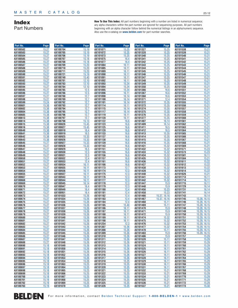
M A S T E R C A T A L O G 23.12
IndexPart Numbers
AX100582 15.27AX100583 15.27AX100584 15.27AX100585 15.27AX100586 15.27AX100587 15.27AX100588 15.27AX100589 15.27AX100590 15.27AX100591 15.27AX100592 15.27AX100593 15.27AX100594 15.27AX100595 15.27AX100596 15.27AX100597 15.27AX100598 15.27AX100599 15.24AX100601 15.38AX100602 15.38AX100604 15.38AX100605 15.38AX100613 15.38AX100614 15.38AX100615 15.38AX100616 15.38AX100640 15.38AX100641 15.38AX100642 15.38AX100643 15.38AX100645 15.27AX100646 15.27AX100647 15.27AX100648 15.27AX100649 15.27AX100650 15.27AX100651 15.27AX100652 15.27AX100653 15.27AX100654 15.27AX100655 15.27AX100667 15.27AX100668 15.27AX100669 15.27AX100670 15.27AX100671 15.27AX100672 15.27AX100673 15.27AX100674 15.27AX100675 15.27AX100676 15.27AX100677 15.27AX100678 15.27AX100679 15.27AX100680 15.27AX100681 15.27AX100682 15.27AX100683 15.27AX100684 15.27AX100685 15.27AX100686 15.27AX100687 15.27AX100688 15.27AX100690 15.18AX100691 15.18AX100692 15.18AX100693 15.18AX100694 15.18AX100695 15.18AX100696 15.18AX100697 15.18AX100698 15.18AX100699 15.18AX100700 15.18AX100701 15.19AX100702 15.19AX100703 15.19
AX100704 15.19AX100705 15.19AX100706 15.19AX100707 15.18AX100708 15.18AX100709 15.20AX100710 15.20AX100711 15.20AX100721 15.19AX100749 15.40AX100781 12.10AX100783 12.10AX100784 12.10AX100785 12.5AX100786 12.5AX100788 12.7AX100789 12.7AX100792 12.7AX100793 12.7AX100794 12.7AX100795 12.7AX100796 12.7AX100797 12.7AX100798 15.13AX100826 15.45AX100827 15.45AX100910 16.4AX100919 16.5AX100925 15.33AX100926 15.33AX100927 15.33AX100928 15.33AX100929 16.5AX100930 12.3AX100931 12.3AX100932 12.4AX100933 12.4AX100934 16.11AX100935 16.11AX100936 16.11AX100937 16.11AX100943 16.11AX100944 16.11AX100945 16.14AX100947 16.4AX100949 16.4AX100951 16.4AX101033 15.26AX101034 15.26AX101035 15.26AX101036 15.26AX101037 15.26AX101038 15.26AX101039 15.26AX101040 15.26AX101041 15.26AX101042 15.26AX101043 15.26AX101044 15.26AX101045 15.26AX101046 15.26AX101047 15.26AX101048 15.26AX101049 15.26AX101050 15.26AX101051 15.26AX101052 15.26AX101053 15.26AX101054 15.26AX101063 15.25AX101064 15.25AX101065 15.25AX101066 15.25AX101067 15.25AX101068 15.25AX101069 15.25AX101070 15.25
AX101071 15.25AX101072 15.25AX101073 15.25AX101075 16.4AX101077 16.4AX101084 16.11AX101085 16.11AX101089 16.11AX101090 16.11AX101091 16.11AX101092 16.11AX101093 15.24AX101094 15.24AX101095 15.24AX101096 16.11AX101098 16.14AX101100 16.14AX101101 16.14AX101114 16.11AX101115 16.14AX101117 16.14AX101119 16.11AX101120 16.11AX101122 16.6AX101123 16.6AX101125 16.6AX101128 16.6AX101133 16.6AX101137 16.6AX101138 16.6AX101139 16.6AX101143 16.6AX101151 16.6AX101155 16.6AX101156 16.6AX101157 16.6AX101161 16.6AX101166 16.6AX101173 12.7AX101174 12.3AX101175 12.3AX101176 12.3AX101177 12.3AX101178 12.3AX101179 12.3AX101180 12.4AX101181 12.4AX101182 12.4AX101183 12.4AX101184 12.4AX101185 15.40AX101186 16.11AX101187 16.11AX101188 16.11AX101189 16.11AX101190 16.11AX101254 12.3AX101307 15.26AX101308 15.26AX101309 15.26AX101310 15.26AX101311 15.26AX101312 15.26AX101313 15.26AX101314 15.26AX101315 15.26AX101316 15.26AX101317 15.26AX101318 15.25AX101319 15.25AX101320 15.25AX101321 15.25AX101322 15.25AX101323 15.25AX101324 15.25AX101325 15.25AX101326 15.25
AX101327 15.25AX101328 15.25AX101340 15.25AX101341 15.25AX101342 15.25AX101343 15.25AX101344 15.25AX101345 15.25AX101346 15.25AX101347 15.25AX101348 15.25AX101349 15.25AX101350 15.25AX101366 16.6AX101367 16.6AX101368 16.6AX101371 12.4AX101372 15.35AX101373 15.35AX101374 15.35AX101375 15.35AX101376 15.35AX101377 15.35AX101407 16.14AX101409 16.14AX101411 16.5AX101412 16.5AX101413 15.35AX101414 15.35AX101415 15.35AX101416 15.35AX101431 15.32AX101432 15.32AX101433 15.32AX101434 15.32AX101435 15.32AX101436 15.32AX101437 15.32AX101438 15.32AX101439 15.32AX101440 15.32AX101441 15.32AX101442 15.32AX101447 15.9AX101448 15.9AX101456 15.23AX101458 15.23AX101466 15.37, 16.16AX101467 15.37, 16.16AX101468 15.11AX101469 15.11AX101470 15.9AX101471 15.9AX101472 15.9AX101474 15.32AX101475 15.32AX101476 15.32AX101477 15.32AX101478 15.11AX101483 15.9AX101486 15.9AX101520 15.11AX101521 15.11AX101524 16.11AX101525 16.11AX101526 16.11AX101527 16.11AX101528 16.11AX101529 16.11AX101530 16.11AX101531 16.11AX101532 15.21AX101533 15.21AX101534 15.21AX101535 15.21AX101536 15.21AX101537 15.21
AX101538 15.21AX101539 15.21AX101540 15.21AX101541 15.21AX101542 15.21AX101543 15.21AX101544 15.21AX101545 15.21AX101546 15.21AX101547 15.21AX101548 15.21AX101549 15.21AX101550 15.21AX101551 15.21AX101552 15.21AX101553 15.21AX101554 15.21AX101555 15.21AX101556 15.21AX101557 15.21AX101558 15.21AX101559 15.21AX101560 15.21AX101561 15.21AX101562 15.21AX101563 15.21AX101564 15.21AX101565 15.21AX101566 15.21AX101567 15.21AX101568 15.21AX101569 15.21AX101571 15.23AX101573 15.23AX101581 16.11AX101584 15.21AX101611 15.22AX101612 15.22AX101613 15.22AX101614 15.22AX101626 15.21AX101713 16.11AX101714 16.11AX101715 16.11AX101729 16.14AX101731 16.14AX101741 16.14AX101743 16.14AX101745 15.28, 16.15AX101746 15.28, 16.15AX101747 15.28, 16.15AX101748 15.28, 16.15AX101749 15.29, 16.15AX101750 15.29, 16.15AX101751 15.29, 16.15AX101752 15.29, 16.15AX101753 15.29, 16.15AX101754 15.29, 16.15AX101755 15.29, 16.15AX101756 15.29, 16.15AX101757 15.29AX101758 15.29AX101759 15.29AX101760 15.29AX101761 15.29AX101762 15.29AX101763 15.29AX101764 15.29AX101765 15.29AX101766 15.29AX101767 15.29AX101768 15.29AX101769 15.29AX101770 15.29AX101771 15.29AX101772 15.29AX101773 15.30
F o r m o r e i n f o r m a t i o n , c o n t a c t B e l d e n Te c h n i c a l S u p p o r t : 1 - 8 0 0 - B E L D E N - 1 • w w w . b e l d e n . c o m
Part No. Page Part No. Page Part No. Page Part No. Page Part No. Page
How To Use This Index: All part numbers beginning with a number are listed in numerical sequence; any alpha characters within the part number are ignored for sequencing purposes. All part numbers beginning with an alpha character follow behind the numerical listings in an alpha/numeric sequence. Also use the e-catalog on www.belden.com for part number searches.

IndexPart Numbers
M A S T E R C A T A L O G 23.13
23•
Part
Num
ber I
ndex
AX101774 15.30AX101775 15.30AX101776 15.30AX101777 15.30AX101778 15.28AX101779 15.28AX101780 15.28AX101781 15.28AX101782 15.28AX101783 15.28AX101784 15.28AX101785 15.28AX101786 15.28AX101787 15.28AX101788 15.28AX101789 15.28AX101790 15.30AX101791 16.4AX101792 16.4AX101793 16.4AX101794 16.4AX101797 16.13AX101798 16.13AX101799 16.13AX101800 16.13AX101801 16.13AX101802 16.13AX101820 15.21AX101821 15.21AX101823 15.37AX101824 15.37AX101825 15.37AX101826 15.37AX101827 15.37AX101828 15.37AX101829 15.37AX101830 15.37AX101831 15.37AX101832 15.37AX101833 15.37AX101834 15.37AX101835 15.37AX101836 15.37AX101837 15.37AX101838 15.37AX101839 15.37AX101840 15.37AX101841 15.37AX101842 15.37AX101852 15.40AX101869 15.28, 16.15AX101870 15.28, 16.15AX101871 15.28, 16.15AX101872 15.28, 16.15AX101873 15.29, 16.15AX101874 15.29, 16.15AX101875 15.29, 16.15AX101876 15.29, 16.15AX101877 15.30AX101878 15.30AX101879 15.30AX101880 15.30AX101881 15.30AX101882 15.30AX101883 15.30AX101884 15.30AX101885 15.30AX101886 15.30AX101887 15.30AX101888 15.30AX101935 15.30, 16.15AX101936 15.30, 16.15AX101937 15.30, 16.15AX101938 15.30, 16.15AX101939 15.30, 16.15AX101940 15.30, 16.15AX101941 15.30, 16.15
AX101942 15.30, 16.15AX101943 16.11AX101944 16.11AX101945 15.10AX101946 15.10AX101947 15.10AX101948 15.10AX101949 15.10AX101950 15.10AX101951 15.10AX101952 15.10AX101953 15.10AX101954 15.10AX101955 15.10AX101956 15.10AX101957 15.10AX101958 15.10AX101959 15.10AX101960 15.10AX101961 15.10AX101962 15.10AX101963 15.10AX101964 15.10AX101965 15.10AX101966 15.10AX101967 15.10AX101968 15.10AX101969 15.10AX101970 15.10AX101971 15.10AX101972 15.10AX101973 15.10AX101974 15.10AX101975 15.10AX101976 15.10AX101977 15.10AX101978 15.10AX101979 15.10AX101980 15.10AX101981 16.4AX101982 16.4AX101983 16.4AX101984 16.4AX101985 15.9AX101986 15.9AX101987 15.9AX102005 15.34AX102006 15.34AX102007 15.34AX102008 15.34AX102009 15.34AX102010 15.34AX102011 15.34AX102012 15.34AX102013 15.34AX102014 15.39AX102015 15.39AX102016 15.39AX102017 15.39AX102018 15.39AX102019 15.39AX102020 15.39AX102021 15.39AX102022 15.39AX102023 15.39AX102024 15.39AX102032 16.11AX102033 16.11AX102061 16.4AX102062 16.4AX102063 16.4AX102073 15.12AX102082 15.12AX102089 16.10AX102090 16.10AX102091 16.10AX102092 16.10
AX102093 16.10AX102094 16.10AX102095 16.10AX102096 16.10AX102097 16.10AX102098 16.10AX102099 16.10AX102100 16.10AX102101 16.10AX102102 16.10AX102103 16.10AX102104 16.10AX102105 16.10AX102106 16.10AX102107 16.10AX102108 16.10AX102109 16.10AX102110 16.10AX102111 16.10AX102112 16.10AX102113 16.10AX102114 16.10AX102115 16.10AX102116 16.10AX102117 16.10AX102118 16.10AX102119 16.10AX102120 16.10AX102121 16.10AX102122 16.10AX102123 16.10AX102124 16.10AX102125 16.10AX102126 16.10AX102127 16.10AX102128 16.10AX102129 16.10AX102130 16.10AX102145 15.12AX102146 15.11AX102147 15.11AX102148 15.11AX102149 15.11AX102150 15.11AX102151 15.11AX102152 15.11AX102153 15.11AX102154 15.11AX102155 15.11AX102156 15.11AX102197 16.9AX102198 16.9AX102199 16.9AX102200 16.9AX102201 16.9AX102202 16.9AX102203 16.9AX102204 16.9AX102205 16.9AX102206 16.9AX102207 16.9AX102208 16.9AX102209 15.37, 16.16AX102210 15.37, 16.16AX102211 15.37, 16.16AX102212 16.16AX102213 15.37, 16.16AX102214 15.37, 16.16AX102215 15.37, 16.16AX102216 15.37, 16.16AX102269 15.6AX102271 15.6AX102272 15.6AX102274 15.6AX102275 15.6AX102276 15.6AX102277 15.6
AX102293 15.6AX102296 15.6AX102305 16.11AX102306 16.11AX102307 16.11AX102308 16.11AX102309 16.11AX102310 16.10AX102311 16.10AX102312 16.10AX102313 16.10AX102314 16.10AX102315 16.10AX102334 15.30AX102335 15.30AX102336 15.30AX102337 15.30AX102480 15.29, 16.15AX102481 15.29, 16.15AX102482 15.29, 16.15AX102483 15.29, 16.15AX102484 15.29, 16.15AX102485 15.29, 16.15AX102488 15.6AX102512 12.10AX102513 12.10AX102514 12.5AX102515 12.10AX102516 12.10AX102517 12.10AX102562 15.6AX102563 15.25AX102564 15.26AX102565 15.26AX102566 15.28AX102567 15.28AX102568 15.28AX102569 15.28, 16.15AX102570 15.28, 16.15AX102571 15.29, 16.15AX102572 15.29, 16.15AX102573 15.29, 16.15AX102574 15.29AX102575 15.29AX102576 15.29AX102577 15.29AX102578 15.30AX102579 15.30AX102580 15.30AX102581 15.30AX102582 15.32AX102583 15.32AX102584 15.32AX102585 15.31AX102586 15.31AX102587 15.31AX102588 15.31AX102589 15.32AX102590 15.33AX102591 15.33AX102592 15.33AX102593 15.33AX102594 15.33AX102595 15.36AX102596 15.37AX102597 15.37AX102598 15.37AX102599 15.37AX102600 15.39AX102601 15.37AX102602 15.37AX102603 15.37AX102604 15.37AX102605 15.37AX102606 15.39AX102607 15.39AX102608 15.28, 16.15
AX102609 15.28, 16.15AX102610 13.3, 15.29, 16.15AX102611 13.3AX102612 15.29, 16.15AX102613 15.29, 16.15AX102614 15.29AX102615 15.29AX102616 15.30AX102617 15.30AX102618 15.30AX102619 15.30, 15.37, 16.15AX102620 15.30, 16.15AX102621 15.28AX102622 15.28AX102623 15.28AX102624 15.37AX102625 15.37AX102626 15.37AX102627 15.37AX102628 15.37AX102630 15.30AX102648 15.33AX102649 15.30, 16.15AX102650 15.30, 16.15AX200056 16.6AX200057 16.6AX200058 16.6AX200060 16.6AX200082 16.6AX200084 16.6AX200090 16.6AX200091 16.6AX200092 16.6AX200094 16.6AX200095 16.6AX200096 16.6AX200097 16.6AX200098 16.6AX200192 16.6AX200196 16.6AX200280 16.6AX200341 16.6AX200413 16.6AX200421 16.6AX200458 16.6AX200459 16.6AX200507 16.6AX200508 16.6AX200509 16.6AX200517 16.6AX200518 16.6AX200519 16.6AX200527 16.6AX200528 16.6AX200529 16.6AX200580 16.6AX200581 16.6AX200589 16.6AX200603 16.6AX200624 16.6AX200653 16.6AX200657 16.6AX200658 16.6AX200659 16.6AX200660 16.6AX200664 16.6AX200665 16.6AX200666 16.6AX200667 16.6AX200668 16.6AX200695 16.6AX200698 16.6AX200699 16.6AX200795 16.6AX200797 16.6AX200799 16.6AX200800 16.6
F o r m o r e i n f o r m a t i o n , c o n t a c t B e l d e n Te c h n i c a l S u p p o r t : 1 - 8 0 0 - B E L D E N - 1 • w w w . b e l d e n . c o m
Part No. Page Part No. Page Part No. Page Part No. Page Part No. Page
How To Use This Index: All part numbers beginning with a number are listed in numerical sequence; any alpha characters within the part number are ignored for sequencing purposes. All part numbers beginning with an alpha character follow behind the numerical listings in an alpha/numeric sequence. Also use the e-catalog on www.belden.com for part number searches.

M A S T E R C A T A L O G 23.14
IndexPart Numbers
AX200801 16.6AX200802 16.6AX200803 16.6AX200809 16.6AX200810 16.6AX200811 16.6AX200812 16.6AX200900 16.6AX201365 16.9AX201366 16.9AX201367 16.9AX201368 16.9AX201369 16.9AX201370 16.9AX201371 16.9AX201372 16.9AX201373 16.9AX201374 16.9AX201375 16.9AX201376 16.9AX201377 16.9AX201378 16.9AX201379 16.9AX201380 16.9AX201381 16.9AX201382 16.9AX201383 16.9AX201384 16.9AX201385 16.9AX201386 16.9AX201387 16.9AX201388 16.9AX201389 16.9AX201390 16.9AX201391 16.9AX201392 16.9AX201393 16.9AX201394 16.9AX201395 16.9AX201396 16.9AX201397 16.9AX201398 16.9AX201399 16.9AX201400 16.9AX201401 16.9AX201402 16.9AX201403 16.9AX201404 16.9AX201405 16.9AX201406 16.9AX201407 16.9AX201408 16.9AX201409 16.9AX201410 16.9AX201411 16.9AX201412 16.9AX201413 16.9AX201414 16.9AX201415 16.9AX201416 16.9AX201417 16.9AX201418 16.9AX201419 16.9AX201420 16.9AX201421 16.9AX201422 16.9AX201423 16.9AX201424 16.9AX201425 16.9AX201426 16.9AX201427 16.9AX201428 16.9AX201429 16.9AX201430 16.9AX201431 16.9AX201432 16.9AX201433 16.9
AX201434 16.9AX201435 16.9AX201436 16.9AX201437 16.9AX201438 16.9AX201439 16.9AX201440 16.9AX201441 16.9AX201442 16.9AX201443 16.9AX201444 16.9AX201445 16.9AX201446 16.9AX201447 16.9AX201448 16.9AX201449 16.9AX201450 16.9AX201451 16.9AX201452 16.9AX201453 16.9AX201454 16.9AX201455 16.9AX201456 16.9AX201457 16.9AX201458 16.9AX201459 16.9AX201460 16.9AX201461 16.9AX201462 16.9AX201463 16.9AX201464 16.9AX201465 16.9AX201466 16.9AX201467 16.9AX201468 16.9AX201469 16.9AX201470 16.9AX201471 16.9AX201472 16.9AX201473 16.9AX201474 16.9AX201475 16.9AX201476 16.9AX201477 16.9AX201478 16.9AX201479 16.9AX201480 16.9AX201481 16.9AX201482 16.9AX201483 16.9AX201484 16.9AX201485 16.9AX201486 16.9AX201487 16.9AX201488 16.9AX201489 16.9AX201490 16.9AX201491 16.9AX201492 16.9AX201493 16.9AX201494 16.9AX201495 16.9AX201496 16.9AX201497 16.9AX201498 16.9AX201499 16.9AX201500 16.9AX201501 16.9AX201502 16.9AX201503 16.9AX201504 16.9AX201505 16.9AX201506 16.9AX201507 16.9AX201508 16.9AX201509 16.9AX201510 16.9
AX201511 16.9AX201512 16.9AX201513 16.9AX201514 16.9AX201515 16.9AX201516 16.9AX201517 16.9AX201518 16.9AX201519 16.9AX201520 16.9AX201521 16.9AX201522 16.9AX201523 16.9AX201524 16.9AX201525 16.9AX201526 16.9AX201527 16.9AX201528 16.9AX201529 16.9AX201530 16.9AX201531 16.9AX201532 16.9AX201533 16.9AX201534 16.9AX201535 16.9AX201536 16.9AX201537 16.9AX201538 16.9AX201539 16.9AX201540 16.9AX201541 16.9AX201542 16.9AX201543 16.9AX201544 16.9AX250001 16.8AX250005 16.8AX250009 16.8AX250011 16.8AX250021 16.7AX250052 16.8AX250054 16.8AX250060 16.7AX250061 16.7AX250065 16.7AX250066 16.7AX250067 16.7AX250071 16.7AX250072 16.7AX250073 16.7AX250105 16.7AX250106 16.7AX250178 16.8AX250179 16.8AX250180 16.8AX250224 16.7AX250345 16.7AX250349 16.7AX250376 16.7AX250387 16.7AX250412 16.7AX250413 16.7AX250457 16.7AX250458 16.7AX250459 16.8AX250460 16.8AX250461 16.8AX250539 16.8AX250540 16.8AX250541 16.8AX250542 16.8AX300001 15.20AX300002 15.20AX300005 15.20AX300006 15.20AX300007 15.20AX300008 15.20AX300009 15.20
AX300010 15.20AX300011 15.20AX300012 15.20AX300013 15.20AX300014 15.20AX300015 15.20AX300017 15.20AX300021 15.20AX300025 15.20AX300026 15.20AX300027 15.20AX300029 15.20AX300030 15.20AX300032 15.20AX300034 15.20AX300037 15.20AX300038 15.20AX300039 15.20AX300040 15.20AX330013 15.42AX330014 15.42AX330015 15.42AX330016 15.42AX330017 15.42AX330018 15.42AX330019 15.42AX330020 15.42AX330021 15.42AX330022 15.42AX330023 15.42AX330024 15.42AX330025 15.42AX330026 15.42AX330027 15.42AX330028 15.42AX330029 15.42AX330030 15.42AX330043 15.42AX330044 15.42AX330045 15.42AX330046 15.42AX330047 15.42AX330048 15.42AX330049 15.42AX330050 15.42AX330051 15.42AX330052 15.42AX330053 15.42AX330054 15.42AX330055 15.42AX330056 15.42AX330057 15.42AX330058 15.42AX330059 15.42AX330060 15.42AX350001 15.42AX350002 15.42AX350003 15.42AX350004 15.42AX350005 15.42AX350006 15.42AX350007 15.42AX350008 15.42AX350009 15.42AX350010 15.42AX350011 15.42AX350012 15.42AX350013 15.42AX350014 15.42AX350015 15.42AX350016 15.42AX350017 15.42AX350018 15.42AX350019 15.42AX350020 15.42AX350021 15.42AX350022 15.42
AX350023 15.42AX350024 15.42AX350025 15.42AX350026 15.42AX350027 15.42AX350028 15.42AX350029 15.42AX350030 15.42AX350031 15.42AX350032 15.42AX350033 15.42AX350034 15.42AX350035 15.42AX350036 15.42AX350037 15.41AX350038 15.41AX350039 15.41AX350040 15.41AX350041 15.41AX350042 15.41AX350043 15.41AX350044 15.41AX350045 15.41AX350046 15.41AX350047 15.41AX350048 15.41AX350049 15.41AX350050 15.41AX350051 15.41AX350052 15.41AX350053 15.41AX350054 15.41AX350055 15.41AX350056 15.41AX350057 15.41AX350058 15.41AX350059 15.41AX350060 15.41AX350061 15.41AX350062 15.41AX350063 15.41AX350064 15.41AX350065 15.41AX350066 15.41AX350067 15.41AX350068 15.41AX350069 15.41AX350070 15.41AX350071 15.41AX350072 15.41AX350160 15.41AX350161 15.41AX350162 15.41AX350163 15.41AX360015 15.7AX360016 15.7AX360017 15.7AX360018 15.7AX360021 15.7AX360022 15.7AX360023 15.7AX360024 15.7AX360027 15.7AX360028 15.7AX360029 15.7AX360030 15.7AX360045 15.7AX360046 15.7AX360047 15.7AX360048 15.7AX360051 15.7AX360052 15.7AX360053 15.7AX360054 15.7AX360057 15.7AX360058 15.7AX360059 15.7
F o r m o r e i n f o r m a t i o n , c o n t a c t B e l d e n Te c h n i c a l S u p p o r t : 1 - 8 0 0 - B E L D E N - 1 • w w w . b e l d e n . c o m
Part No. Page Part No. Page Part No. Page Part No. Page Part No. Page
How To Use This Index: All part numbers beginning with a number are listed in numerical sequence; any alpha characters within the part number are ignored for sequencing purposes. All part numbers beginning with an alpha character follow behind the numerical listings in an alpha/numeric sequence. Also use the e-catalog on www.belden.com for part number searches.

IndexPart Numbers
M A S T E R C A T A L O G 23.15
23•
Part
Num
ber I
ndex
AX360060 15.7AX360265 15.7AX360266 15.7AX360267 15.7AX360268 15.7AX360269 15.7AX360270 15.7AX360271 15.7AX360272 15.7AX380014 15.41AX380015 15.41AX380016 15.41AX380017 15.41AX380018 15.41AX380026 15.41AX380027 15.41AX380028 15.41AX380029 15.41AX380030 15.41AX380050 15.41AX380051 15.41AX380052 15.41AX380053 15.41AX380054 15.41AX380056 15.41AX380057 15.41AX380058 15.41AX380059 15.41AX380060 15.41B2418-TP-1-C 11.11B2418-TP-2-C 11.11B2418-TP-3-C 11.11B2418-TP-4-C 11.11B2430-TP-1-C 11.14, 11.17B2430-TP-3-C 11.14, 11.17B2430-TP-4-C 11.14, 11.17B2430-TP-6-C 11.14, 11.17B2918-TP-1-C 11.5, 11.8B2918-TP-2-C 11.5, 11.8B2918-TP-3-C 11.5, 11.8B2918-TP-4-C 11.5, 11.8B433-5114 11.17B433-5115-F 11.17B433-5115-R 11.17B433-5118 11.17B4801-SP-C 11.5, 11.11B4802-SP-C 11.5, 11.11B4824-FR-C 11.11B4824-GF-C 11.11B4824-PD-C 11.11B4824-SF-C 11.11B4824-SR-C 11.11B4824-VF-C 11.11B4824-VR-C 11.11B4829-FR-C 11.5B4829-GF-C 11.5B4829-PD-C 11.5B4829-SF-C 11.5B4829-SR-C 11.5B4829-VF-C 11.5B4829-VR-C 11.5B7201-SP-C 11.5, 11.8, 11.11B7202-SP-C 11.5, 11.8, 11.11B7224-FR-C 11.11B7224-GF-C 11.11B7224-PD-C 11.11B7224-SF-C 11.11B7224-SR-C 11.11B7224-VF-C 11.11B7224-VR-C 11.11B7229-FR-C 11.5, 11.8B7229-GF-C 11.5, 11.8B7229-PD-C 11.5, 11.8B7229-SF-C 11.5, 11.8B7229-SR-C 11.5, 11.8B7229-VF-C 11.5, 11.8B7229-VR-C 11.5, 11.8
B7801-SP-C 11.5, 11.8, 11.11B7802-SP-C 11.5, 11.8, 11.11B7824-FR-C 11.11B7824-GF-C 11.11B7824-PD-C 11.11B7824-SF-C 11.11B7824-SPR-C 11.14B7824-SR-C 11.11B7824-SVF-C 11.14B7824-VF-C 11.11B7824-VR-C 11.11B7829-FR-C 11.5, 11.8B7829-GF-C 11.5, 11.8B7829-PD-C 11.5, 11.8B7829-SF-C 11.5, 11.8B7829-SR-C 11.5, 11.8B7829-VF-C 11.5, 11.8B7829-VR-C 11.5, 11.8B7836-01-SP-C 11.14B7836-02-SP-C 11.14B8401-SP-C 11.5, 11.8, 11.11B8402-SP-C 11.5, 11.8, 11.11B8424-DSPR-C 11.17B8424-DSSR-C 11.17B8424-DSVF-C 11.17B8424-DSVR-C 11.17B8424-FR-C 11.11B8424-GF-C 11.11B8424-PD-C 11.11B8424-SF-C 11.11B8424-SPR-C 11.14B8424-SR-C 11.11B8424-SVF-C 11.14B8424-VF-C 11.11B8424-VR-C 11.11B8429-FR-C 11.5, 11.8B8429-GF-C 11.5, 11.8B8429-PD-C 11.5, 11.8B8429-SF-C 11.5, 11.8B8429-SR-C 11.5, 11.8B8429-VF-C 11.5, 11.8B8429-VR-C 11.5, 11.8B8436-01-SP-C 11.14, 11.17B8436-01-SPP-C 11.17B8436-02-SP-C 11.14, 11.17B8436-02-SPP-C 11.17B8910-0100 11.22B8911-0100 11.22B8912-0100 12.3B8912-0200-C 11.29B8913-0100 11.22B8914-0100 11.22B8915-0100 11.22B9010-1924 11.20B9010-1924-Q 11.20B9010-1930 11.20B9010-1930-Q 11.20B9010-1936 11.20B9011-1912 11.20B9011-1918 11.20B9011-1918-16 11.20B9012-1918 11.20B9012-1918-16 11.20B9013-1930 11.20B9013-1936 11.20B9014-1907 11.20B9015-1902 11.20B9015-1909 11.20B9015-1924 11.20B9016-1921 11.20B9016-1921-3 11.20B9017-0200 11.20B9110-2324 11.21B9111-2318 11.21B9112-2318 11.21B9113-2324 11.21B9114-2307 11.21
B9210-2923 11.21B9211-2917 11.21B9212-2922 11.21B9309-0100 11.20B9315-7200 11.14, 11.17B9318-0200 11.27B9318-0300 11.27B9318-0400 11.27B9411-1602 11.25B9412-0801 11.25B9413-0601 11.25B9414-0602 11.25B9415-1601 11.25B9415-1602 11.25B9415-1603 11.25B9415-1606 11.25B9415-1607 11.25B9415-1608 11.25B9415-1610 11.25B9416-1001 11.25B9418-0801 11.26B9418-0802 11.26B9418-1201 11.26B9418-2401 11.26B9418-2402 11.26B9418-2403 11.26B9418-2410 11.26B9418-4801 11.26B9418-7201 11.26B9420-1905 11.24B9420-1906 11.24B9510-1901 12.6B9511-1902 12.6B9512-1901 12.6B9512-1902 12.6B9512-1902-FR 12.6B9513-1902 12.6B9514-1901 12.6B9610-2301 12.6B9611-2302 12.6B9712-0100 11.24B9712-0101 11.24B9712-0102 11.24B9712-0103 11.24B9712-0106 11.24B9712-0107 11.24B9712-0108 11.24B9712-0109 11.24B9712-0109S 11.24B9713-0200 11.24B9713-0201 11.24B9713-0202 11.24B9714-0190 11.22B9714-0720 11.22B9810-0100 12.6B9811-0200 12.6B9812-0300 12.6B9813-0400 12.6B9910-0100 12.6B9911-0200 12.6B9912-0300 12.6B9913-0400 12.6B9914-0200 12.6B9915-0300 12.6B9916-0400 12.6BCR-8419 12.4BCR-8419-10 12.4BDP7219-23 11.23BDP7219-23SQ 11.23BDP7819-23 11.23BDP8419-23 11.23BDP84-3-100000 11.7BDP84-3-122226 11.7BDP-ATD-0200-3 11.22BDR-4819 12.3BDR-7201 12.3BDR-7219 12.3
BDR-7223 12.3BDR-8401 12.3BDR-8403 12.3BDR-8419 12.3BDR-8419-4 12.3BDR-8423 12.3BER-3UC 12.5BER-6UP 12.5BER-6X6 12.5BER-AS 12.5BFT-03SRW8 13.2BFT-05SRW8 13.2BFT-09SRW8 13.2BFT-3T03W 13.3BFT-3T05W 13.3BFT-3T09W 13.3BFT-4T03W 13.3BFT-4T05W 13.3BFT-4T09W 13.3BFT-9003W 13.3BFT-9005W 13.3BFT-9009W 13.3BFT-CE03W 13.3BFT-CE05W 13.3BFT-CE09W 13.3BFT-EC03W 13.3BFT-EC05W 13.3BFT-EC09W 13.3BFT-FO03W 13.3BFT-FO05W 13.3BFT-FO09W 13.3BFT-IN03W 13.3BFT-IN05W 13.3BFT-IN09W 13.3BFT-OC03W 13.3BFT-OC05W 13.3BFT-OC09W 13.3BFT-SC03W 13.3BFT-SC05W 13.3BFT-SC09W 13.3BGS84-3-100000 11.19BGS84-3-112346 11.19BRL-3006-0300 11.23BRL-3012-0200 11.23BRL-3024-0100 11.23BSL/BST-ATD-0300-3 11.22BSL7219 11.23BSL7219SQ-2 11.23BSL7819 11.23BSL8419 11.23BSL84-3-100000 11.10BSL84-3-122226 11.10BSR-8419-24 12.4BSR-8419-28 12.4BSR-8419-32 12.4BSR-8419-36 12.4BSR-8423-24 12.4BSR-8423-28 12.4BSR-8423-32 12.4BSR-8423-36 12.4BST4819-23 11.23BST7219-23 11.23BST7819-23 11.23BST8419-23 11.23BST8419-23SQ 11.23BST84-3-100000 11.4BST84-3-122226 11.4BST-ATD-0030-3 11.22BSW-0100 11.29BSW-0200 11.29BSW-8419 11.29BUS84-3-100000 11.13BUS84-3-122226 11.13BUS-ATD-0010-C 11.22BUSD84-3-100000 11.16BUSD84-3-122226 11.16BWM-2401 11.29
BWM-2406-GD-C 11.28BWM-2406-SD-C 11.28BWM-2419 11.29BWM-2420-GD-C 11.28BWM-2420-SD-C 11.28BWM-2424-GD-C 11.28BWM-2424-SD-C 11.28BWM-3601 11.29BWM-3606-GD-C 11.28BWM-3606-SD-C 11.28BWM-3619 11.29BWM-3620-GD-C 11.28BWM-3620-SD-C 11.28BWM-3624-GD-C 11.28BWM-3624-SD-C 11.28BWM-4801 11.29BWM-4806-GD-C 11.28BWM-4806-SD-C 11.28BWM-4819 11.29BWM-4820-GD-C 11.28BWM-4820-SD-C 11.28BWM-4824-GD-C 11.28BWM-4824-SD-C 11.28BWM-4830-SD-3S0001 11.28BWM-9312-1600 11.29BWR-1219 12.5BWR-3619-12 12.5BWR-3619-18 12.5BWR-4819 12.5BWR-4819-12 12.5BWR-4819-18 12.5C0039222 15.17C0054642 15.17C5500 18.89C5501 18.89C5502 18.89C5503 18.89C5504 18.89C5505 18.89C5506 18.89C5508 18.89C5510 18.89C5513 18.89C5518 18.89C5523 18.89C5528 18.89C5529 18.89C5530 18.89C5531 18.89C5532 18.89C5533 18.89C5534 18.89C5535 18.89C5536 18.89C5538 18.89C5540 18.89C5543 18.89C5548 18.89C5553 18.89C5558 18.89C5560 18.90C5561 18.90C5562 18.90C5563 18.90C5564 18.90C5565 18.90C5566 18.90C5568 18.90C5570 18.90C5573 18.90C5578 18.90C5579 18.90C5580 18.90C5581 18.90, 18.92C5582 18.90, 18.92C5583 18.90, 18.92C5590 18.93
F o r m o r e i n f o r m a t i o n , c o n t a c t B e l d e n Te c h n i c a l S u p p o r t : 1 - 8 0 0 - B E L D E N - 1 • w w w . b e l d e n . c o m
Part No. Page Part No. Page Part No. Page Part No. Page Part No. Page
How To Use This Index: All part numbers beginning with a number are listed in numerical sequence; any alpha characters within the part number are ignored for sequencing purposes. All part numbers beginning with an alpha character follow behind the numerical listings in an alpha/numeric sequence. Also use the e-catalog on www.belden.com for part number searches.
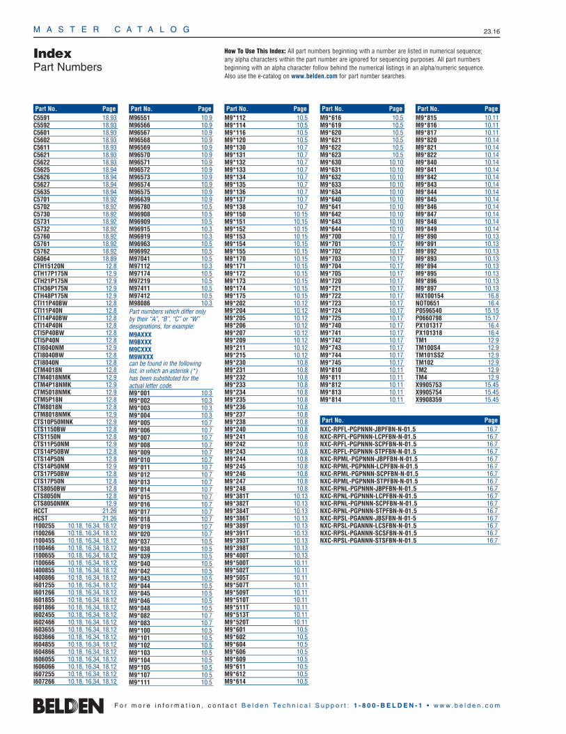
M A S T E R C A T A L O G 23.16
IndexPart Numbers
C5591 18.93C5592 18.93C5601 18.93C5602 18.93C5611 18.93C5621 18.93C5622 18.93C5625 18.94C5626 18.94C5627 18.94C5635 18.94C5701 18.92C5702 18.92C5730 18.92C5731 18.92C5732 18.92C5760 18.92C5761 18.92C5762 18.92C6064 18.89CTH15120N 12.8CTH17P175N 12.9CTH21P175N 12.9CTH36P175N 12.9CTH48P175N 12.9CTI11P40BW 12.8CTI11P40N 12.8CTI14P40BW 12.8CTI14P40N 12.8CTI5P40BW 12.8CTI5P40N 12.8CTI6040NM 12.9CTI8040BW 12.8CTI8040N 12.8CTM4018N 12.8CTM4018NMK 12.9CTM4P18NMK 12.9CTM5018NMK 12.9CTM5P18N 12.8CTM8018N 12.8CTM8018NMK 12.9CTS10P50MNK 12.9CTS1150BW 12.8CTS1150N 12.8CTS11P50NM 12.9CTS14P50BW 12.8CTS14P50N 12.8CTS14P50NM 12.9CTS17P50BW 12.8CTS17P50N 12.8CTS8050BW 12.8CTS8050N 12.8CTS8050NMK 12.9HCCT 21.26HCST 21.26I100255 10.18, 16.34, 18.12I100266 10.18, 16.34, 18.12I100455 10.18, 16.34, 18.12I100466 10.18, 16.34, 18.12I100655 10.18, 16.34, 18.12I100666 10.18, 16.34, 18.12I400855 10.18, 16.34, 18.12I400866 10.18, 16.34, 18.12I601255 10.18, 16.34, 18.12I601266 10.18, 16.34, 18.12I601855 10.18, 16.34, 18.12I601866 10.18, 16.34, 18.12I602455 10.18, 16.34, 18.12I602466 10.18, 16.34, 18.12I603655 10.18, 16.34, 18.12I603666 10.18, 16.34, 18.12I604855 10.18, 16.34, 18.12I604866 10.18, 16.34, 18.12I606055 10.18, 16.34, 18.12I606066 10.18, 16.34, 18.12I607255 10.18, 16.34, 18.12I607266 10.18, 16.34, 18.12
M96551 10.9M96566 10.9M96567 10.9M96568 10.9M96569 10.9M96570 10.9M96571 10.9M96572 10.9M96573 10.9M96574 10.9M96575 10.9M96639 10.9M96780 10.5M96908 10.5M96909 10.5M96915 10.3M96919 10.3M96963 10.5M96992 10.5M97041 10.5M97112 10.3M97174 10.5M97219 10.5M97411 10.5M97412 10.5M98086 10.3Part numbers which differ only by their “A”, “B”, “C” or “W” designations, for example:M9AXXXM9BXXXM9CXXXM9WXXXcan be found in the following list, in which an asterisk (*) has been substituted for the actual letter code.M9*001 10.3M9*002 10.3M9*003 10.3M9*004 10.3M9*005 10.7M9*006 10.7M9*007 10.7M9*008 10.7M9*009 10.7M9*010 10.7M9*011 10.7M9*012 10.7M9*013 10.7M9*014 10.7M9*015 10.7M9*016 10.7M9*017 10.7M9*018 10.7M9*019 10.7M9*020 10.7M9*037 10.5M9*038 10.5M9*039 10.5M9*040 10.5M9*042 10.5M9*043 10.5M9*044 10.5M9*045 10.5M9*046 10.5M9*048 10.5M9*082 10.7M9*083 10.7M9*100 10.5M9*101 10.5M9*102 10.5M9*103 10.5M9*104 10.5M9*105 10.5M9*107 10.5M9*111 10.5
M9*112 10.5M9*114 10.5M9*116 10.5M9*120 10.5M9*130 10.7M9*131 10.7M9*132 10.7M9*133 10.7M9*134 10.7M9*135 10.7M9*136 10.7M9*137 10.7M9*138 10.7M9*150 10.15M9*151 10.15M9*152 10.15M9*153 10.15M9*154 10.15M9*155 10.15M9*170 10.15M9*171 10.15M9*172 10.15M9*173 10.15M9*174 10.15M9*175 10.15M9*202 10.12M9*204 10.12M9*205 10.12M9*206 10.12M9*207 10.12M9*209 10.12M9*211 10.12M9*215 10.12M9*230 10.8M9*231 10.8M9*232 10.8M9*233 10.8M9*234 10.8M9*235 10.8M9*236 10.8M9*237 10.8M9*238 10.8M9*240 10.8M9*241 10.8M9*242 10.8M9*243 10.8M9*244 10.8M9*245 10.8M9*246 10.8M9*247 10.8M9*248 10.8M9*381T 10.13M9*382T 10.13M9*384T 10.13M9*386T 10.13M9*389T 10.13M9*391T 10.13M9*393T 10.13M9*398T 10.13M9*400T 10.13M9*500T 10.11M9*502T 10.11M9*505T 10.11M9*507T 10.11M9*509T 10.11M9*510T 10.11M9*511T 10.11M9*513T 10.11M9*520T 10.11M9*601 10.5M9*602 10.5M9*604 10.5M9*606 10.5M9*609 10.5M9*611 10.5M9*612 10.5M9*614 10.5
M9*616 10.5M9*619 10.5M9*620 10.5M9*621 10.5M9*622 10.5M9*623 10.5M9*630 10.10M9*631 10.10M9*632 10.10M9*633 10.10M9*634 10.10M9*640 10.10M9*641 10.10M9*642 10.10M9*643 10.10M9*644 10.10M9*700 10.17M9*701 10.17M9*702 10.17M9*703 10.17M9*704 10.17M9*705 10.17M9*720 10.17M9*721 10.17M9*722 10.17M9*723 10.17M9*724 10.17M9*725 10.17M9*740 10.17M9*741 10.17M9*742 10.17M9*743 10.17M9*744 10.17M9*745 10.17M9*810 10.11M9*811 10.11M9*812 10.11M9*813 10.11M9*814 10.11
M9*815 10.11M9*816 10.11M9*817 10.11M9*820 10.14M9*821 10.14M9*822 10.14M9*840 10.14M9*841 10.14M9*842 10.14M9*843 10.14M9*844 10.14M9*845 10.14M9*846 10.14M9*847 10.14M9*848 10.14M9*849 10.14M9*890 10.13M9*891 10.13M9*892 10.13M9*893 10.13M9*894 10.13M9*895 10.13M9*896 10.13M9*897 10.13MX100154 16.8NOT0651 16.4P0596540 15.15P0660798 15.17PX101317 16.4PX101318 16.4TM1 12.9TM100S4 12.9TM101SS2 12.9TM102 12.9TM2 12.9TM4 12.9X9905753 15.45X9905754 15.45X9908359 15.45
F o r m o r e i n f o r m a t i o n , c o n t a c t B e l d e n Te c h n i c a l S u p p o r t : 1 - 8 0 0 - B E L D E N - 1 • w w w . b e l d e n . c o m
Part No. Page Part No. Page Part No. Page Part No. Page Part No. Page
Part No. Page
How To Use This Index: All part numbers beginning with a number are listed in numerical sequence; any alpha characters within the part number are ignored for sequencing purposes. All part numbers beginning with an alpha character follow behind the numerical listings in an alpha/numeric sequence. Also use the e-catalog on www.belden.com for part number searches.
NXC-RPFL-PGPNNN-JBPFBN-N-01.5 16.7NXC-RPFL-PGPNNN-LCPFBN-N-01.5 16.7NXC-RPFL-PGPNNN-SCPFBN-N-01.5 16.7NXC-RPFL-PGPNNN-STPFBN-N-01.5 16.7NXC-RPML-PGPNNN-JBPFBN-N-01.5 16.7NXC-RPML-PGPNNN-LCPFBN-N-01.5 16.7NXC-RPML-PGPNNN-SCPFBN-N-01.5 16.7NXC-RPML-PGPNNN-STPFBN-N-01.5 16.7NXC-RPNL-PGPNNN-JBPFBN-N-01.5 16.7NXC-RPNL-PGPNNN-LCPFBN-N-01.5 16.7NXC-RPNL-PGPNNN-SCPFBN-N-01.5 16.7NXC-RPNL-PGPNNN-STPFBN-N-01.5 16.7NXC-RPSL-PGANNN-JBSFBN-N-01-5 16.7NXC-RPSL-PGANNN-LCSFBN-N-01.5 16.7NXC-RPSL-PGANNN-SCSFBN-N-01.5 16.7NXC-RPSL-PGANNN-STSFBN-N-01.5 16.7

CYAN MAGENTA YELLOW BLACK PMS 280 Anthology 606188
Belden® Customer Care
Belden has maintained its leadership role in the industry primarily because of the emphasis we place on customers’needs. By staying close to the customer,the various markets we serve and theapplicable industry standards, Belden has always been able to meet or exceed the expectations of all.
Customer-Centric Design™ (CCD) is the phrase we’ve coined for our productdevelopment process, which encompassesso much more than the act of designing a product for a customer. It really meansconstant care – taking care to stay at the
top of our craft in every wayimaginable. From the time
that a customer’s needis established to the end of the product or system’s life cycle,Belden provides ongoing support
at all times.
Customer-Centric Design Offers Tangible Rewards
When our customers are teamed with our skilled engineering and sales staff it’s a win-win opportunity for everyone. Thiscombined effort typically provides our customers with:
• Expertise in technical problem solving• Innovative designs to match
specific applications
• Enhanced performance• Cost-effective solutions
Raising the Bar on Customer Satisfaction
As we go forward, we recognize that ourcustomers’ needs will continue to evolve.We’re committed to evolving with them by taking our solutions provider status a step further.
We are extending our Customer-Centricdesign capabilities to all aspects of signaltransmission technology - applying ourservice support and technical know-howto this decidedly broader sphere.
Evidence of our expanded scope is appar-ent by our addition of new copper andoptical fiber cabling products and systems,end-to-end structured cabling systems,enclosures and racks, Power over Ethernet(PoE) equipment, cable managementaccessories – and we are not through.
So, whether you need a standard signal transmission product, a modificationof an existing product, or a customdesigned product and system for your application, just ask.
Belden is Fully Committed to Your Needs.
For All Your Signal Transmission Needs...
Be Sure To Specify Belden
Our Signal
Transmission
Solutions Exemplify
the Reliability and
Expert Care You
Have Come to
Expect from Belden
Belden®
: The Brand You Depend On
Our New Logo and Tagline Embody Our Commitment:
We focus on being the brand you trust for any number of signal transmission solutions…the brand you candepend on for the “right” signals.
Over and over again our customers tell us that Belden is the brand theytrust for dependable signal transmis-sion. No matter the market – broad-cast, commercial networking, security,industrial or residential – the name‘Belden’ has become synonymous withhigh quality and ensured reliability.
We have earned our reputation as an expert solutions provider preciselybecause our customers are now, and
have always been, our #1 priority. We make it our job to consistently
supply innovative, standard-setting products upon which
customers can rely.
We offer the broadest selection of signal transmission products available.We provide all the data and supportnecessary to help you make the rightdecision for the intended application.And, Belden products are readily available to you, no matter wherearound the globe you may be.
Belden is also evolving. We are taking our success in cable to all means ofsignal transmission technology: copper,optical fiber and wireless. And we haveexpanded our product offering toinclude complete system solutions,including connectivity, equipmentenclosures, cable raceways and racks.
Take a look at the first wave of our evolution, embodied within these pages – being mindful that even more dynamic products, systems and services are sure to come.
©Copyright 2006, Belden Inc.
5818-1004595 Innerworkings: Belden Master Catalog IFC_IBC
2006Cat_Cover_X 7/20/06 12:01 PM Page 2

5818-1004595 Innerworkings: Belden Master Catalog OBC-OFC CYAN MAGENTA YELLOW BLACK PMS 280 Anthology 606188
Master CatalogCOPPER CABLE & CONNECTIVITY
FIBER OPTIC CABLE & CONNECTIVITY
CABLE MANAGEMENT SOLUTIONS
POWER OVER ETHERNET PRODUCTS
Signal Transmission Products and Systems
Signal Transmission
Products and Systems
Master C
atalog
2006
ASIA/PACIFIC
AustraliaLevel 10369 Royal ParadeParkville, Victoria 3052AustraliaPhone: 613-9341-0900Fax: [email protected]
BeijingRm 1015Office Tower Beijing CapitalTimes SquareNo. 88 West Changan Ave.Beijing 100031People’s Republic of ChinaPhone: 8610-8391-5181-3Fax: [email protected]
Hong KongUnit 4401, 44FCosco TowerGrand Millennium Plaza183 Queen’s Road CentralHong KongPhone: 852-2955-0128Fax: [email protected]
IndiaSuite 203, Enkay TowersUdyog Vihar Phase VGurgaon 122016NCR, IndiaPhone: +91-124-401-4739Fax: [email protected]
ShanghaiUnit 2605Harbour Ring Plaza18 Xi Zang Zhong RoadShanghai 200001People’s Republic of ChinaPhone: 8621-5385-3355Fax: [email protected]
Singapore101 Thomson Road#21-01 United SquareSingapore 307591Phone: 65-6251-8211Fax: [email protected]
©Copyright 2006, Belden Inc. Printed in U. S. A. MCAT 2006
UNITED STATES
Division Headquarters–Americas2200 U.S. Highway 27 SouthRichmond, IN 47374Phone: 765-983-5200Inside Sales: 800-235-3361Fax: [email protected]: www.belden.com
793 Fort Mill HighwayFort Mill, SC 29715Phone: 800-331-0779Fax: [email protected]
www.belden.com
U.S. Customer Service: 800-BELDEN-1 (800-235-3361)
MEXICO/CARIBBEAN/SOUTH AMERICA
Regional Office6100 Hollywood BoulevardSuite 110Hollywood, Florida 33024Phone: 954-987-5044Fax: [email protected]
MexicoInsurgentes Sur 800, Piso 9Colonia del Valle03100 Mexico, D.F.MexicoPhone: 5255-5523-7733Fax: [email protected]
South AmericaRua dos Pinheiros, 245, Conjunto 2Pinheiros 05422-010 Sao Paulo, SP BrasilPhone: 5511-3061-3099Fax: [email protected]
CANADA EUROPE/AFRICA/MIDDLE EAST
Cobourg130 Willmott StreetCobourg, Ontario K9A 4M3CanadaPhone: 905-372-8713Fax: [email protected]
Montreal 2345 Boulevard des SourcesPointe Claire, QuebecCanada H9R 5Z3Phone: 800-681-6131Fax: [email protected]
FranceImmeuble le Cesar20, Place Louis Pradel69001 LyonFrancePhone: 33-472-109-990Fax: [email protected]
ItalyVia Paracelso, 26Centro Direzionale ColleoniPalazzo Cassiopea Ingr. 320041 Agrate Brianza (MI)ItalyPhone: 39 039 656 0911Fax: 39 029 656 [email protected]
Africa/Middle EastP.O. Box #500158Dubai Internet CityBuilding One, Office 216DubaiUnited Arab EmiratesPhone: 97-14-391-0490Fax: [email protected]
The NetherlandsDivision Headquarters –EuropeEdisonstraat 9, Postus 95928 PG Venlo, 5900 AAThe NetherlandsPhone: 31-773-878-555Fax: [email protected]
United Kingdom3000 Manchester Business ParkAviator WayManchester M22 5TGUnited KingdomPhone: +44-161-266-1115Fax: [email protected]
2006Cat_Cover_X 7/20/06 12:00 PM Page 1