ul 1479 - national fire protection association - nfpa.org · pdf filefor committee use only,...
TRANSCRIPT
FOR COMMITTEE U
SE ONLY
, NOT FOR S
ALE O
R DIS
TRIBUTIO
N
UL 1479
Fire Tests of Through-Penetration Firestops

FOR COMMITTEE U
SE ONLY
, NOT FOR S
ALE O
R DIS
TRIBUTIO
N
FOR COMMITTEE U
SE ONLY
, NOT FOR S
ALE O
R DIS
TRIBUTIO
N
UL Standard for Safety for Fire Tests of Through-Penetration Firestops, UL 1479
Third Edition, Dated May 23, 2003
Summary of Topics
These revisions to ANSI/UL 1479 are being issued to correct the revisions issued on February16, 2010, by correcting the ANSI approval date.
Text that has been changed in any manner or impacted by UL’s electronic publishing system is markedwith a vertical line in the margin. Changes in requirements are marked with a vertical line in the marginand are followed by an effective date note indicating the date of publication or the date on which thechanged requirement becomes effective.
All rights reserved. No part of this publication may be reproduced, stored in a retrieval system, ortransmitted in any form by any means, electronic, mechanical photocopying, recording, or otherwisewithout prior permission of UL.
UL provides this Standard ″as is″ without warranty of any kind, either expressed or implied, including butnot limited to, the implied warranties of merchantability or fitness for any purpose.
In no event will UL be liable for any special, incidental, consequential, indirect or similar damages,including loss of profits, lost savings, loss of data, or any other damages arising out of the use of or theinability to use this Standard, even if UL or an authorized UL representative has been advised of thepossibility of such damage. In no event shall UL’s liability for any damage ever exceed the price paid forthis Standard, regardless of the form of the claim.
Users of the electronic versions of UL’s Standards for Safety agree to defend, indemnify, and hold ULharmless from and against any loss, expense, liability, damage, claim, or judgment (including reasonableattorney’s fees) resulting from any error or deviation introduced while purchaser is storing an electronicStandard on the purchaser’s computer system.
The requirements in this Standard are now in effect, except for those paragraphs, sections, tables, figures,and/or other elements of the Standard having future effective dates as indicated in the note following theaffected item. The prior text for requirements that have been revised and that have a future effective dateare located after the Standard, and are preceded by a ″SUPERSEDED REQUIREMENTS″ notice.
MARCH 1, 2010 − UL 1479 tr1

FOR COMMITTEE U
SE ONLY
, NOT FOR S
ALE O
R DIS
TRIBUTIO
N
MARCH 1, 2010 − UL 1479tr2
No Text on This Page
FOR COMMITTEE U
SE ONLY
, NOT FOR S
ALE O
R DIS
TRIBUTIO
N
MAY 23, 2003(Title Page Reprinted: March 1, 2010)
1
UL 1479
Standard for Fire Tests of Through-Penetration Firestops
Prior to the first edition, the requirements for the products covered by thisstandard were included in the Standard for Fire Tests of Building Constructionand Materials, UL 263, and in the Standard for Fire Tests of Door Assemblies, UL10B.
First Edition – January, 1983Second Edition – June, 1994
Third Edition
May 23, 2003
This ANSI/UL Standard for Safety consists of the Third Edition including revisionsthrough March 1, 2010.
The most recent designation of ANSI/UL 1479 as an American National Standard(ANSI) occurred on February 23, 2010. ANSI approval for a standard does notinclude the Cover Page, Transmittal Pages, Title Page, or effective dateinformation.
Comments or proposals for revisions on any part of the Standard may besubmitted to UL at any time. Proposals should be submitted via a ProposalRequest in UL’s On-Line Collaborative Standards Development System (CSDS)at http://csds.ul.com.
UL’s Standards for Safety are copyrighted by UL. Neither a printed nor electroniccopy of a Standard should be altered in any way. All of UL’s Standards and allcopyrights, ownerships, and rights regarding those Standards shall remain thesole and exclusive property of UL.
COPYRIGHT © 2010 UNDERWRITERS LABORATORIES INC.
ANSI/UL 1479-2010

FOR COMMITTEE U
SE ONLY
, NOT FOR S
ALE O
R DIS
TRIBUTIO
N
DECEMBER 10, 2008FIRE TESTS OF THROUGH-PENETRATION FIRESTOPS - UL 14792
No Text on This Page
FOR COMMITTEE U
SE ONLY
, NOT FOR S
ALE O
R DIS
TRIBUTIO
N
CONTENTS
INTRODUCTION
1 Scope . . . . . . . . . . . . . . . . . . . . . . . . . . . . . . . . . . . . . . . . . . . . . . . . . . . . . . . . . . . . . . . . . . . . . . . . . . . . . . .72 General . . . . . . . . . . . . . . . . . . . . . . . . . . . . . . . . . . . . . . . . . . . . . . . . . . . . . . . . . . . . . . . . . . . . . . . . . . . . . .8
2.1 Units of measurement . . . . . . . . . . . . . . . . . . . . . . . . . . . . . . . . . . . . . . . . . . . . . . . . . . . . . . . . . . .82.2 References . . . . . . . . . . . . . . . . . . . . . . . . . . . . . . . . . . . . . . . . . . . . . . . . . . . . . . . . . . . . . . . . . . . .8
3 Glossary . . . . . . . . . . . . . . . . . . . . . . . . . . . . . . . . . . . . . . . . . . . . . . . . . . . . . . . . . . . . . . . . . . . . . . . . . . . . .8
PERFORMANCE
4 Fire Exposure Test . . . . . . . . . . . . . . . . . . . . . . . . . . . . . . . . . . . . . . . . . . . . . . . . . . . . . . . . . . . . . . . . . . . .94.1 Test sample . . . . . . . . . . . . . . . . . . . . . . . . . . . . . . . . . . . . . . . . . . . . . . . . . . . . . . . . . . . . . . . . . . .94.2 Conditioning . . . . . . . . . . . . . . . . . . . . . . . . . . . . . . . . . . . . . . . . . . . . . . . . . . . . . . . . . . . . . . . . . .104.3 Protection of assembly and sample . . . . . . . . . . . . . . . . . . . . . . . . . . . . . . . . . . . . . . . . . . . . . .104.4 Furnace temperature control and measurement . . . . . . . . . . . . . . . . . . . . . . . . . . . . . . . . . .10A4.5 Furnace thermocouple preparation . . . . . . . . . . . . . . . . . . . . . . . . . . . . . . . . . . . . . . . . . . . . . .124.6 Unexposed side temperature measurement . . . . . . . . . . . . . . . . . . . . . . . . . . . . . . . . . . . . . . .144.7 Differential pressure measurements . . . . . . . . . . . . . . . . . . . . . . . . . . . . . . . . . . . . . . . . . . . . .164.8 Duration of test . . . . . . . . . . . . . . . . . . . . . . . . . . . . . . . . . . . . . . . . . . . . . . . . . . . . . . . . . . . . . . . .17
5 Hose Stream Test . . . . . . . . . . . . . . . . . . . . . . . . . . . . . . . . . . . . . . . . . . . . . . . . . . . . . . . . . . . . . . . . . . .176 Air Leakage Test . . . . . . . . . . . . . . . . . . . . . . . . . . . . . . . . . . . . . . . . . . . . . . . . . . . . . . . . . . . . . . . . . . . .18
6.1 Test sample . . . . . . . . . . . . . . . . . . . . . . . . . . . . . . . . . . . . . . . . . . . . . . . . . . . . . . . . . . . . . . . . . .186.2 Conditioning . . . . . . . . . . . . . . . . . . . . . . . . . . . . . . . . . . . . . . . . . . . . . . . . . . . . . . . . . . . . . . . . . .186.3 Test chamber . . . . . . . . . . . . . . . . . . . . . . . . . . . . . . . . . . . . . . . . . . . . . . . . . . . . . . . . . . . . . . . . .196.4 Test setup . . . . . . . . . . . . . . . . . . . . . . . . . . . . . . . . . . . . . . . . . . . . . . . . . . . . . . . . . . . . . . . . . . . .196.5 Extraneous chamber leakage requirements . . . . . . . . . . . . . . . . . . . . . . . . . . . . . . . . . . . . . . .206.6 Ambient temperature exposure tests . . . . . . . . . . . . . . . . . . . . . . . . . . . . . . . . . . . . . . . . . . . . .206.7 Elevated temperature exposure tests . . . . . . . . . . . . . . . . . . . . . . . . . . . . . . . . . . . . . . . . . . .20A6.8 Recorded test data . . . . . . . . . . . . . . . . . . . . . . . . . . . . . . . . . . . . . . . . . . . . . . . . . . . . . . . . . . .20A
6A Water Leakage Test . . . . . . . . . . . . . . . . . . . . . . . . . . . . . . . . . . . . . . . . . . . . . . . . . . . . . . . . . . . . . . .20A6A.1 Test sample . . . . . . . . . . . . . . . . . . . . . . . . . . . . . . . . . . . . . . . . . . . . . . . . . . . . . . . . . . . . . . . .20A6A.2 Test chamber . . . . . . . . . . . . . . . . . . . . . . . . . . . . . . . . . . . . . . . . . . . . . . . . . . . . . . . . . . . . . .20B6A.3 Test setup . . . . . . . . . . . . . . . . . . . . . . . . . . . . . . . . . . . . . . . . . . . . . . . . . . . . . . . . . . . . . . . . .20B6A.4 Recorded test data . . . . . . . . . . . . . . . . . . . . . . . . . . . . . . . . . . . . . . . . . . . . . . . . . . . . . . . . .20C
7 Environmental Exposure Tests for Intumescent Material . . . . . . . . . . . . . . . . . . . . . . . . . . . . . . . . .20C7.1 General . . . . . . . . . . . . . . . . . . . . . . . . . . . . . . . . . . . . . . . . . . . . . . . . . . . . . . . . . . . . . . . . . . . . .20C7.2 Required environmental exposures . . . . . . . . . . . . . . . . . . . . . . . . . . . . . . . . . . . . . . . . . . . . .20C7.3 Supplemental environmental exposures . . . . . . . . . . . . . . . . . . . . . . . . . . . . . . . . . . . . . . . . .20C7.4 Expansion pressure test . . . . . . . . . . . . . . . . . . . . . . . . . . . . . . . . . . . . . . . . . . . . . . . . . . . . . .20D7.5 Expansion factor test . . . . . . . . . . . . . . . . . . . . . . . . . . . . . . . . . . . . . . . . . . . . . . . . . . . . . . . . . .21
RATING
8 F Rating . . . . . . . . . . . . . . . . . . . . . . . . . . . . . . . . . . . . . . . . . . . . . . . . . . . . . . . . . . . . . . . . . . . . . . . . . . . .229 T Rating . . . . . . . . . . . . . . . . . . . . . . . . . . . . . . . . . . . . . . . . . . . . . . . . . . . . . . . . . . . . . . . . . . . . . . . . . . . .2210 L Rating . . . . . . . . . . . . . . . . . . . . . . . . . . . . . . . . . . . . . . . . . . . . . . . . . . . . . . . . . . . . . . . . . . . . . . . . . . .2210A W rating . . . . . . . . . . . . . . . . . . . . . . . . . . . . . . . . . . . . . . . . . . . . . . . . . . . . . . . . . . . . . . . . . . . . . . . . . .2311 Fire Exposure Correction . . . . . . . . . . . . . . . . . . . . . . . . . . . . . . . . . . . . . . . . . . . . . . . . . . . . . . . . . . .24A
DECEMBER 10, 2008 FIRE TESTS OF THROUGH-PENETRATION FIRESTOPS - UL 1479 3

FOR COMMITTEE U
SE ONLY
, NOT FOR S
ALE O
R DIS
TRIBUTIO
N
REPORT
12 Results . . . . . . . . . . . . . . . . . . . . . . . . . . . . . . . . . . . . . . . . . . . . . . . . . . . . . . . . . . . . . . . . . . . . . . . . . . . .25
APPENDIX A
A.1 Background information for the W-Rating . . . . . . . . . . . . . . . . . . . . . . . . . . . . . . . . . . . . . . . . . . . . .A1
APRIL 4, 2008FIRE TESTS OF THROUGH-PENETRATION FIRESTOPS - UL 14794

FOR COMMITTEE U
SE ONLY
, NOT FOR S
ALE O
R DIS
TRIBUTIO
N
MARCH 10, 2006 FIRE TESTS OF THROUGH-PENETRATION FIRESTOPS - UL 1479 5
No Text on This Page

FOR COMMITTEE U
SE ONLY
, NOT FOR S
ALE O
R DIS
TRIBUTIO
N
This page intentionally left blank.
MARCH 10, 2006FIRE TESTS OF THROUGH-PENETRATION FIRESTOPS - UL 14796
FOR COMMITTEE U
SE ONLY
, NOT FOR S
ALE O
R DIS
TRIBUTIO
N
INTRODUCTION
1 Scope
1.1 These requirements cover through-penetration firestops of various materials and construction that areintended for use in openings in fire resistive wall or floor-ceiling assemblies, or both.
1.2 The method of testing through-penetration firestops as specified by these requirements consists ofexposure of test samples to a fire of standard time and temperature and to an application of a hosestream. Ratings are then established on the basis of:
a) The length of time the firestop resists fire before the first development of through openingsor flaming on the unexposed surface,
b) Acceptable limitation of thermal transmission, and
c) Acceptable performance under the application of the hose stream.1.2 revised and separated into 1.2.1 – 1.2.4 March 10, 2006
1.2.1 The method of testing also includes optional air leakage tests to determine the rate of air leakagethrough through-penetration firestop systems resulting from a specified air pressure difference appliedacross the surface of the systems.
1.2 revised and separated into 1.2.1 – 1.2.4 March 10, 2006
1.2.2 The method of testing also includes optional water leakage tests to determine the ability ofthrough-penetration firestop systems to resist the passage of water under a three foot pressure head. Thismethod does not evaluate the ability of uncured firestop systems to resist such exposure.
1.2 revised and separated into 1.2.1 – 1.2.4 March 10, 2006
1.2.3 Two ratings are established for each through-penetration firestop system: an F rating based uponflame occurrence on the unexposed side of the test sample and acceptable hose stream performance;and a T rating based on temperature rise and flame occurrence on the unexposed side of the test sampleand acceptable hose stream performance.
1.2 revised and separated into 1.2.1 – 1.2.4 March 10, 2006
1.2.4 An L rating may also be established for a through-penetration firestop system. The L rating is basedon the amount of air leakage through the test sample.
1.2 revised and separated into 1.2.1 – 1.2.4 March 10, 2006
1.2.5 An W rating may also be established for a through-penetration firestop system. The W rating isbased on the water resistance of the test sample.
1.2.5 added March 10, 2006
1.3 The method of testing through-penetration firestop systems containing piping systems for vented(drain, waste or vent) systems and closed (process or supply) systems is differentiated by the capping ornon-capping of the piping systems on the unexposed side of the test assembly as described in 4.1.2.
MARCH 10, 2006 FIRE TESTS OF THROUGH-PENETRATION FIRESTOPS - UL 1479 7
FOR COMMITTEE U
SE ONLY
, NOT FOR S
ALE O
R DIS
TRIBUTIO
N
1.4 Tests conducted in accordance with these requirements are intended to demonstrate theperformance of through-penetration firestops during exposure to fire, but are not intended to determineacceptability of firestops for use after exposure to fire. These requirements do not cover the ampacity ofconductors encased in through-penetration firestop materials.
1.5 The results obtained from the air leakage tests are expressed in cubic feet per minute (cubic meterper second) per square foot (square meter) of opening. The results are intended to develop data to assistauthorities having jurisdiction, and others, in determining the acceptability of through-penetration firestopswith reference to the control of air movement through the assembly.
1.6 These requirements do not cover devices that penetrate fire resistive floors and walls but terminateon the opposite side, as, for example, an outlet box and fitting.
2 General
2.1 Units of measurement
2.1.1 Values stated without parentheses are the requirement. Values in parentheses are explanatory orapproximate information.
2.2 References
2.2.1 Any undated reference to a code or standard appearing in the requirements of this standard shallbe interpreted as referring to the latest edition of that code or standard.
3 Glossary
3.1 For the purpose of this standard the following definitions apply.
3.2 AIR-FLOW METERING SYSTEM – A device used to measure the air flow.
3.3 AIR LEAKAGE (Q) – The volume of air flowing, per unit of time, through the openings around thetest sample under a test pressure difference, expressed as cubic feet per minute (m3/s). This airleakage volume is to be reported standardized to an ambient air temperature of 75°F (24°C).
3.4 AIR LEAKAGE TEST CHAMBER – A sealed chamber or box with an opening, a removablemounting panel, or one open side in which or against which the test sample is installed and sealed.
3.5 AIR SYSTEM – A controllable blower, compressed air supply, exhaust system, or reversible blowerdesigned to provide an essentially constant required air flow at the specified fixed test pressuredifference for the period required to obtain readings of air leakage.
3.6 AMBIENT TEMPERATURE EXPOSURE – The temperature at the exposed face of the test sampleis to be 75 ±20°F (24 ±11°C).
3.7 ELEVATED TEMPERATURE EXPOSURE – The temperature at the exposed face of the testsample is to be 400 ±10°F (204 ±5°C).
3.8 EXTRANEOUS LEAKAGE (QL) – The difference between the metered air flow (Qm) and the airleakage (Q).
3.9 METERED AIR FLOW (Qm) – The volume of air flowing per unit of time through the air flowmetering system, expressed as cubic feet per minute (m3/s).
MARCH 10, 2006FIRE TESTS OF THROUGH-PENETRATION FIRESTOPS - UL 14798
FOR COMMITTEE U
SE ONLY
, NOT FOR S
ALE O
R DIS
TRIBUTIO
N
3.10 RATE OF AIR LEAKAGE – The total air leakage per sample, expressed as cubic feet per minute(m3/s) per square foot (square meter) of opening.
3.11 REPLACEMENT AIR – The volume of air, at ambient temperature, added to the test chamber, toreplace the air leakage (Q) volume of air in either the ambient or elevated temperature exposure tests.
3.12 TEST ASSEMBLY – The wall or floor into which the test sample is mounted or installed.
3.13 TEST PRESSURE DIFFERENCE – The specified difference in static air pressure across the fixedtest sample, expressed as inch of water column (Pa).
3.14 TEST SAMPLE – The through-penetration firestop being tested.
MARCH 10, 2006 FIRE TESTS OF THROUGH-PENETRATION FIRESTOPS - UL 1479 8A

FOR COMMITTEE U
SE ONLY
, NOT FOR S
ALE O
R DIS
TRIBUTIO
N
MARCH 10, 2006FIRE TESTS OF THROUGH-PENETRATION FIRESTOPS - UL 14798B
No Text on This Page

FOR COMMITTEE U
SE ONLY
, NOT FOR S
ALE O
R DIS
TRIBUTIO
N
3.15 THROUGH-PENETRATION FIRESTOP – A specific construction consisting of:
a) The material(s) that fills the opening and
b) The penetrating items, such as cables, cable trays, conduits, ducts, and pipes, along withtheir means of support through the wall or floor opening, that is intended to prevent spread offire.
PERFORMANCE
4 Fire Exposure Test
4.1 Test sample
4.1.1 Each representative construction type of through-penetration firestop for which rating is desired isto be tested. When a through-penetration firestop is intended for use in both floor and walls, eachorientation is to be tested unless it is demonstrated that testing in a single orientation does not affect thetest results.
4.1.2 Penetrating items are to be installed in the test sample so that they extend 12 ±1 inch (300 ±25 mm)from the exposed side, and 36 ±1 inch (910 ±25 mm) from the unexposed side. The extended portions ofthe penetrating items on the unexposed side are to be supported by methods intended to be employed infield installation. The individual ends of the penetrating items are to be covered on the exposed side toprevent excessive transfer of gases through the test sample. When the penetrating item is intended to berepresentative of a closed system that is not normally vented or open to the atmosphere, the penetratingitem can also be capped or sealed on the unexposed side. Otherwise, penetrating items shall not becapped or sealed on the unexposed side.
4.1.2.1 Penetrating items of horizontal assemblies are to be exposed to the furnace temperatures for thespecified distance of 12 ±1 inch (300 ±25 mm) from the plane representing the bottom surface of a floorassembly or floor/ceiling assembly and shall not be contained within the cavity of a wall under testconditions regardless of whether the intended application involves a completely exposed penetrant or onewhich may be fully or partially contained within the cavity of a wall.
Added 4.1.2.1 effective September 20, 2007
4.1.3 The periphery of the test sample is to be not closer than 1-1/2 times the thickness of the testassembly, or a minimum of 12 inches (300 mm), to the furnace edge, whichever is greater. The distancebetween the test sample periphery and furnace edge can be reduced if it is demonstrated that the edgeeffects do not affect the test results.
SEPTEMBER 20, 2006 FIRE TESTS OF THROUGH-PENETRATION FIRESTOPS - UL 1479 9
FOR COMMITTEE U
SE ONLY
, NOT FOR S
ALE O
R DIS
TRIBUTIO
N
4.2 Conditioning
4.2.1 Prior to fire testing, each test sample and test assembly is to be conditioned, if necessary, toprovide a moisture condition representative of that likely to exist in similarly-constructed buildings. The testassembly can be conditioned independent of the conditioning of the test samples. The moisture conditionis to be established by storage in air having 50 percent relative humidity at 73°F (23°C) until an equilibriummoisture condition is achieved. If it is impractical to achieve this equilibrium moisture condition, the testcan be conducted when the dampest portion of the test assembly and test sample have achieved anequilibrium moisture content resulting from storage in air having 50 to 75 percent relative humidity at 73±5°F (23 ±3°C).
Exception: These requirements can be waived if:
a) An equilibrium moisture condition is not achieved within a 12-month conditioning period, or
b) The construction is such that hermetic sealing resulting from the conditioning has preventeddrying of the interior of the test sample or assembly, in which case the conditioning need thenbe continued only until the test assembly has developed sufficient strength to retain the testsample securely in position.
4.2.2 The method for determining the relative humidity within hardened concrete by use of electricsensing elements is described in Appendix I of a paper by Carl A. Menzel, ″A Method for Determining theMoisture Condition of Hardened Concrete in Terms of Relative Humidity,″ Proceedings, ASTM, Volume55, Page 1085 (1955). A similar procedure with electric sensing elements can be used to determine therelative humidity within a test assembly and test sample made of materials other than concrete.
4.3 Protection of assembly and sample
4.3.1 The testing equipment and test sample and assembly are to be protected from any condition of windor weather that might influence the test results. The ambient air temperature at the beginning of the testis to lie within the range of 50 to 90°F (10 to 32°C). The velocity of air across the unexposed surface ofthe test sample, measured immediately before the test begins, is not to exceed 4.4 feet per second (1.3m/s) as determined by an anemometer placed at right angles to the unexposed surface. If mechanicalventilation is employed during the test, an air stream is not to be directed across the surface of thesample.
SEPTEMBER 20, 2006FIRE TESTS OF THROUGH-PENETRATION FIRESTOPS - UL 147910
FOR COMMITTEE U
SE ONLY
, NOT FOR S
ALE O
R DIS
TRIBUTIO
N
4.4 Furnace temperature control and measurement
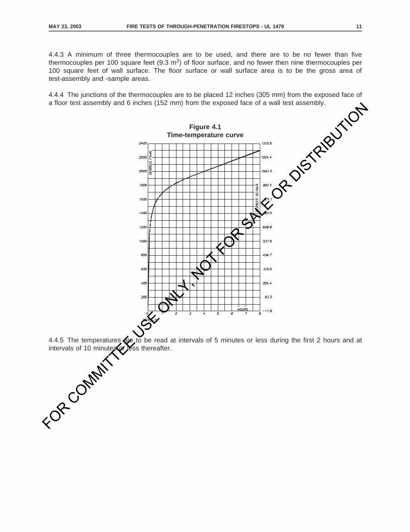
4.4.1 The temperature of the furnace is to be controlled so that the area under the measuredtemperature-time curve of furnace temperature, obtained by averaging the results from thermocouple (see4.4.5 – 4.6.1.2) or pyrometer readings, is within 10 percent of the corresponding area under the standardtemperature-time curve illustrated in Figure 4.1 for fire tests for 1 hour or less duration, within 7.5 percentfor tests longer than 1 hour but not longer than 2 hours, and within 5 percent for tests exceeding 2 hoursin duration. The points on the curve that determine its character are:
50 – 90°F (10 to 32°C) at 0 minutes
1000°F (538°C) at 5 minutes
1300°F (704°C) at 10 minutes
1550°F (843°C) at 30 minutes
1700°F (927°C) at 1 hour
1850°F (1010°C) at 2 hours
2000°F (1093°C) at 4 hours
2300°F (1260°C) at 8 hours
For a more precise definition of the temperature-time curve, see Table 4.1.
4.4.2 The measured temperature to be compared with the standard temperature-time curve is to be theaverage temperature obtained from the readings of thermocouples symmetrically disposed and distributedwithin the test furnace to indicate the temperature near all parts of the test assembly.
SEPTEMBER 20, 2006 FIRE TESTS OF THROUGH-PENETRATION FIRESTOPS - UL 1479 10A

FOR COMMITTEE U
SE ONLY
, NOT FOR S
ALE O
R DIS
TRIBUTIO
N
SEPTEMBER 20, 2006FIRE TESTS OF THROUGH-PENETRATION FIRESTOPS - UL 147910B
No Text on This Page
FOR COMMITTEE U
SE ONLY
, NOT FOR S
ALE O
R DIS
TRIBUTIO
N
4.4.3 A minimum of three thermocouples are to be used, and there are to be no fewer than fivethermocouples per 100 square feet (9.3 m2) of floor surface, and no fewer then nine thermocouples per100 square feet of wall surface. The floor surface or wall surface area is to be the gross area oftest-assembly and -sample areas.
4.4.4 The junctions of the thermocouples are to be placed 12 inches (305 mm) from the exposed face ofa floor test assembly and 6 inches (152 mm) from the exposed face of a wall test assembly.This is generated text for figtxt.
4.4.5 The temperatures are to be read at intervals of 5 minutes or less during the first 2 hours and atintervals of 10 minutes or less thereafter.
Figure 4.1Time-temperature curve
MAY 23, 2003 FIRE TESTS OF THROUGH-PENETRATION FIRESTOPS - UL 1479 11
FOR COMMITTEE U
SE ONLY
, NOT FOR S
ALE O
R DIS
TRIBUTIO
N
4.5 Furnace thermocouple preparation
4.5.1 Each furnace thermocouple is to be enclosed in a sealed protection tube. The exposed combinedlength of protection tube and thermocouple in the furnace chamber is to be not less than 12 inches (0.3m). Other types of protection tubes can be used provided that the temperature measurements are withinthe limits of accuracy specified in 4.5.2.
4.5.2 The time constant of the protected thermocouple assembly is to lie within the range of 5.0 to 7.2minutes. A typical thermocouple assembly complying with this time constant requirement can befabricated by fusion-welding the twisted ends of 18 AWG (0.82 mm2) chromel-alumel wires, mounting theleads in porcelain insulators and inserting the assembly into a standard weight nominal 1/2-inch iron,steel, or inconel pipe, and sealing the end of the pipe that is inside the furnace. The thermocouple junctionis to be inside the pipe, 1/2 inch (13 mm) from the sealed end.
4.5.2 revised April 4, 2008
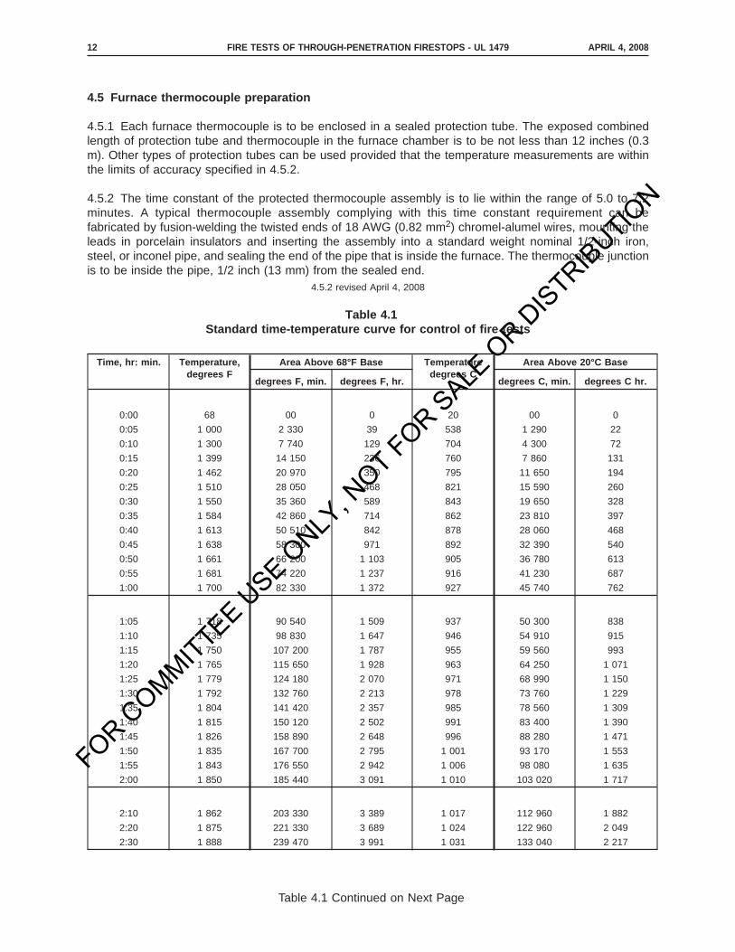
Table 4.1Standard time-temperature curve for control of fire tests
Time, hr: min. Temperature,degrees F
Area Above 68°F Base Temperaturedegrees C
Area Above 20°C Base
degrees F, min. degrees F, hr. degrees C, min. degrees C hr.
0:00 68 00 0 20 00 0
0:05 1 000 2 330 39 538 1 290 22
0:10 1 300 7 740 129 704 4 300 72
0:15 1 399 14 150 236 760 7 860 131
0:20 1 462 20 970 350 795 11 650 194
0:25 1 510 28 050 468 821 15 590 260
0:30 1 550 35 360 589 843 19 650 328
0:35 1 584 42 860 714 862 23 810 397
0:40 1 613 50 510 842 878 28 060 468
0:45 1 638 58 300 971 892 32 390 540
0:50 1 661 66 200 1 103 905 36 780 613
0:55 1 681 74 220 1 237 916 41 230 687
1:00 1 700 82 330 1 372 927 45 740 762
1:05 1 718 90 540 1 509 937 50 300 838
1:10 1 735 98 830 1 647 946 54 910 915
1:15 1 750 107 200 1 787 955 59 560 993
1:20 1 765 115 650 1 928 963 64 250 1 071
1:25 1 779 124 180 2 070 971 68 990 1 150
1:30 1 792 132 760 2 213 978 73 760 1 229
1:35 1 804 141 420 2 357 985 78 560 1 309
1:40 1 815 150 120 2 502 991 83 400 1 390
1:45 1 826 158 890 2 648 996 88 280 1 471
1:50 1 835 167 700 2 795 1 001 93 170 1 553
1:55 1 843 176 550 2 942 1 006 98 080 1 635
2:00 1 850 185 440 3 091 1 010 103 020 1 717
2:10 1 862 203 330 3 389 1 017 112 960 1 882
2:20 1 875 221 330 3 689 1 024 122 960 2 049
2:30 1 888 239 470 3 991 1 031 133 040 2 217
APRIL 4, 2008FIRE TESTS OF THROUGH-PENETRATION FIRESTOPS - UL 147912
Table 4.1 Continued on Next Page

FOR COMMITTEE U
SE ONLY
, NOT FOR S
ALE O
R DIS
TRIBUTIO
N
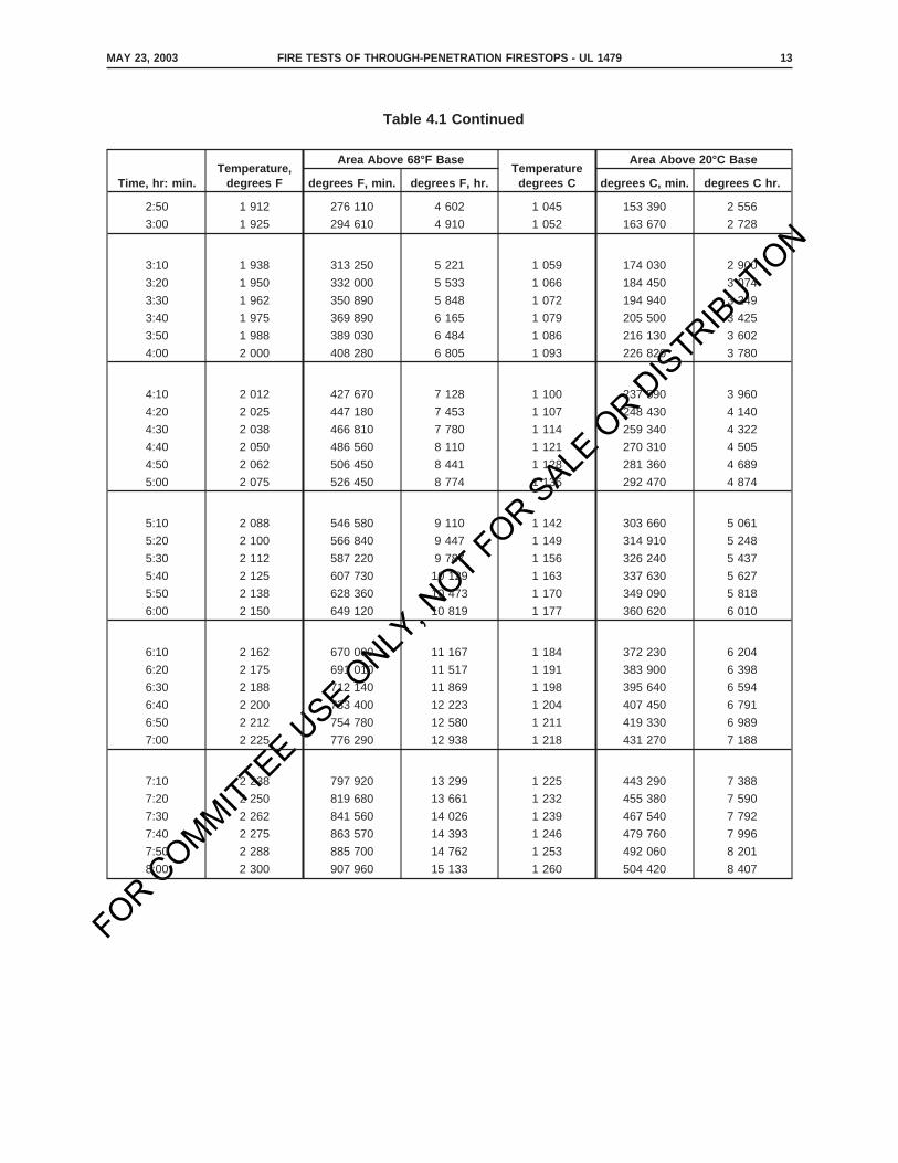
Table 4.1 Continued
Time, hr: min. Temperature,degrees F
Area Above 68°F Base Temperaturedegrees C
Area Above 20°C Base
degrees F, min. degrees F, hr. degrees C, min. degrees C hr.
2:40 1 900 257 720 4 295 1 038 143 180 2 386
APRIL 4, 2008 FIRE TESTS OF THROUGH-PENETRATION FIRESTOPS - UL 1479 12A
Table 4.1 Continued on Next Page

FOR COMMITTEE U
SE ONLY
, NOT FOR S
ALE O
R DIS
TRIBUTIO
N
APRIL 4, 2008FIRE TESTS OF THROUGH-PENETRATION FIRESTOPS - UL 147912B
No Text on This Page
FOR COMMITTEE U
SE ONLY
, NOT FOR S
ALE O
R DIS
TRIBUTIO
N
Table 4.1 Continued
Time, hr: min.Temperature,
degrees F
Area Above 68°F BaseTemperature
degrees C
Area Above 20°C Base
degrees F, min. degrees F, hr. degrees C, min. degrees C hr.
2:50 1 912 276 110 4 602 1 045 153 390 2 556
3:00 1 925 294 610 4 910 1 052 163 670 2 728
3:10 1 938 313 250 5 221 1 059 174 030 2 900
3:20 1 950 332 000 5 533 1 066 184 450 3 074
3:30 1 962 350 890 5 848 1 072 194 940 3 249
3:40 1 975 369 890 6 165 1 079 205 500 3 425
3:50 1 988 389 030 6 484 1 086 216 130 3 602
4:00 2 000 408 280 6 805 1 093 226 820 3 780
4:10 2 012 427 670 7 128 1 100 237 590 3 960
4:20 2 025 447 180 7 453 1 107 248 430 4 140
4:30 2 038 466 810 7 780 1 114 259 340 4 322
4:40 2 050 486 560 8 110 1 121 270 310 4 505
4:50 2 062 506 450 8 441 1 128 281 360 4 689
5:00 2 075 526 450 8 774 1 135 292 470 4 874
5:10 2 088 546 580 9 110 1 142 303 660 5 061
5:20 2 100 566 840 9 447 1 149 314 910 5 248
5:30 2 112 587 220 9 787 1 156 326 240 5 437
5:40 2 125 607 730 10 129 1 163 337 630 5 627
5:50 2 138 628 360 10 473 1 170 349 090 5 818
6:00 2 150 649 120 10 819 1 177 360 620 6 010
6:10 2 162 670 000 11 167 1 184 372 230 6 204
6:20 2 175 691 010 11 517 1 191 383 900 6 398
6:30 2 188 712 140 11 869 1 198 395 640 6 594
6:40 2 200 733 400 12 223 1 204 407 450 6 791
6:50 2 212 754 780 12 580 1 211 419 330 6 989
7:00 2 225 776 290 12 938 1 218 431 270 7 188
7:10 2 238 797 920 13 299 1 225 443 290 7 388
7:20 2 250 819 680 13 661 1 232 455 380 7 590
7:30 2 262 841 560 14 026 1 239 467 540 7 792
7:40 2 275 863 570 14 393 1 246 479 760 7 996
7:50 2 288 885 700 14 762 1 253 492 060 8 201
8:00 2 300 907 960 15 133 1 260 504 420 8 407
MAY 23, 2003 FIRE TESTS OF THROUGH-PENETRATION FIRESTOPS - UL 1479 13

FOR COMMITTEE U
SE ONLY
, NOT FOR S
ALE O
R DIS
TRIBUTIO
N
4.6 Unexposed side temperature measurement
4.6.1 Sample thermocouple location
4.6.1.1 Temperature measurements are to be made by thermocouples placed at each of the followinglocations on the unexposed side of the test sample and test assembly, as illustrated in Figure 4.2.
a) At a point on the surface of the test sample, 1 inch (25 mm) from one of each type ofthrough-penetrating item employed in the field of the through-penetration firestop material.Thermocouples are to be covered by a pad (see 4.6.1.3 and 4.6.2.1); however, if the groupingof items through the test sample does not permit use of a pad, the thermocouple need not beused.
b) At a minimum of one point on the through-penetration firestop material surface at theperiphery of the test sample.
c) At least three points on the through-penetration firestop material surfaces approximatelyequidistant from a penetrating item or group of penetrating items in the field of the firestop andthe periphery.
d) At a point on any frame installed around the perimeter of the opening.
e) At a point on the unexposed surface of the wall or floor assembly at least 12 inches (0.3 m)from any opening.
f) At one point on each type of through-penetrating item. On each type of through-penetratingitem at a point 1 inch (25 mm) from the unexposed surface of the test assembly. When thethrough-penetrating item is insulated or coated on the unexposed side, the thermocouple shallbe located on the exterior surface of the insulation or coating. When the insulation or coatingdoes not extend the full length of the penetrating item on the unexposed side, an additionalthermocouple shall be installed on the penetrating item 1 inch (25 mm) beyond the terminationof the insulation or coating.
This is generated text for figtxt.
MAY 23, 2003FIRE TESTS OF THROUGH-PENETRATION FIRESTOPS - UL 147914

FOR COMMITTEE U
SE ONLY
, NOT FOR S
ALE O
R DIS
TRIBUTIO
N
4.6.1.2 Temperature measurements can be made at locations in addition to those described in 4.6.1.1 forthe purpose of evaluating the performance of the firestop.
4.6.1.3 Temperatures on the surface of the through-penetration firestop and test assembly are to bemeasured with thermocouples placed under flexible pads (see 4.6.2.1). The pads are to be held firmlyagainst the surface and are to fit closely about the thermocouples. Each thermocouple junction is to belocated under the center of each pad. The thermocouple leads under the pads are to be not larger than18 AWG (0.82 mm2) and are to be electrically insulated with heat- and moisture-resistant coverings.
4.6.1.3 revised April 4, 2008
4.6.1.4 Where temperature measurements are being made on the penetrating item, the thermocouplebead is to be held firmly against the penetrating item. The thermocouple leads are not to be larger than22 AWG (0.32 mm2) and are to be electrically insulated with heat and moisture-resistant coverings. Thepads, as described in 4.6.2.1, are to be held firmly against the penetrating item and are to fit closely aboutthe thermocouples.
4.6.1.4 revised April 4, 2008
4.6.1.5 Temperatures are to be measured at intervals of 15 minutes or less until a reading exceeding212°F (100°C) has been obtained at any one point. Thereafter, the readings can be taken more frequentlyat the discretion of testing personnel, but the intervals need not be less than 5 minutes.
Figure 4.2Temperature measurements locations a
a See 4.6.1.1 for description of letter symbols
APRIL 4, 2008 FIRE TESTS OF THROUGH-PENETRATION FIRESTOPS - UL 1479 15
FOR COMMITTEE U
SE ONLY
, NOT FOR S
ALE O
R DIS
TRIBUTIO
N
4.6.2 Thermocouple pads
4.6.2.1 Each thermocouple used to measure temperatures on the unexposed side of the sample andassembly is to be covered with a flexible pad that:
a) Is of inorganic material that can be bent without breaking,
b) Has a length and a width of 2 ±0.04 inch (50 ±1 mm),
c) Is 0.40 ±0.05 inch (10 ±1 mm) thick,
d) Has a density of 31.2 ±0.6 pounds per cubic foot (500 ±10 kg/m3), and
e) Has a thermal conductivity at 150°F (65.6°C) of 0.38 ±0.027 Btu inch per hour per squarefoot per degree F (0.055 ±0.0039 W/m·K).
4.7 Differential pressure measurements
4.7.1 General
4.7.1.1 The appropriate differential pressure between the exposed and unexposed surfaces of the testassembly (see 4.7.3.1) is to be measured no less frequently than once every minute.
4.7.1.1 revised December 10, 2008
This is generated text for figtxt.
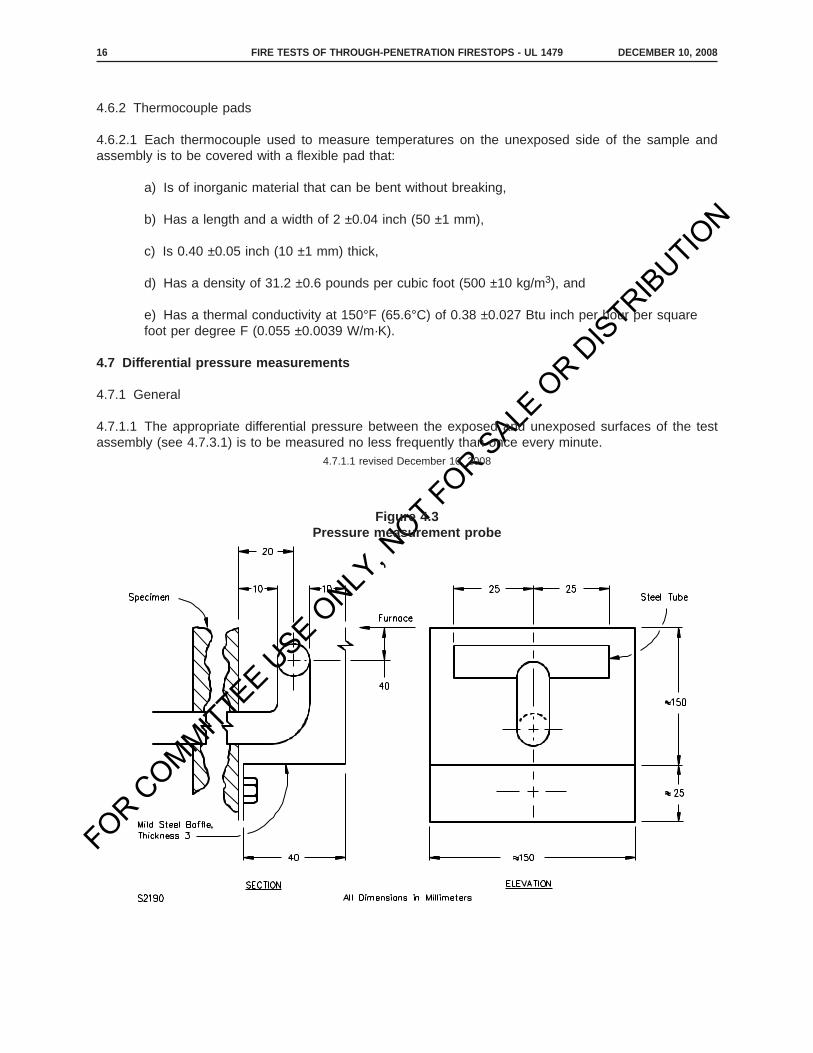
Figure 4.3Pressure measurement probe
DECEMBER 10, 2008FIRE TESTS OF THROUGH-PENETRATION FIRESTOPS - UL 147916
FOR COMMITTEE U
SE ONLY
, NOT FOR S
ALE O
R DIS
TRIBUTIO
N
4.7.1.2 The differential pressure between the exposed and unexposed surfaces of the test assembly is tobe measured at sufficient locations to determine the specified pressure differential. The pressure sensorsshall be located where they will not be subject to direct impingement of convection currents from theflames or in the path of the exhaust gases. Tubing connected to the pressure sensors shall be horizontalboth in the furnace and as they exit through the furnace wall, such that the pressure is relative to the samepositional height from the inside to the outside of the furnace.
4.7.2 Pressure measurement apparatus
4.7.2.1 The differential pressure between the exposed and the unexposed surface of the test assembly isto be measured by means of a manometer or equivalent transducer capable of reading pressure withinan accuracy of 0.01 inch water (2.5 Pa) increments.
4.7.2.2 The pressure measuring probe tips are to be as illustrated in Figure 4.3 or the equivalent, andmanufactured from stainless steel or equivalent material.
4.7.3 Differential pressure selection
4.7.3.1 Excluding the first 5 minutes of the test, the furnace pressure differential shall be a minimum of0.01 inch of water (2.5 Pa) at a distance of 12 inches (305 mm) from the surface of horizontal testassemblies and a minimum of 0.01 inch of water (2.5 Pa) at a level 0.78 inch (20 mm) below the lowestlevel of materials that fill openings surrounding penetrating items passing through vertical test assemblies.
Exception: Atmospheric changes (or other causes which result in the test chamber dropping below thespecified 0.01 inch of water pressure) shall not be considered unacceptable provided such drops do notexceed 1 minute in duration and collectively do not exceed 5% of the test time.
4.7.3.1 revised December 10, 2008
4.8 Duration of test
4.8.1 The test sample and assembly are to be subjected to fire exposure for a period equal to the desiredF rating (see Section 7) for the firestop or until a through opening develops in, or flaming occurs on theunexposed side of, the test sample; whichever is less.
5 Hose Stream Test
5.1 A duplicate test sample and test assembly is to be subjected to a fire exposure test for a period equalto one-half of the desired F rating (see Section 8) but not more than 60 minutes. Immediately after the fireexposure, the test sample is to be subjected to the impact, erosion, and cooling effects of a hose stream,as described in the Standard Practice for Application of Hose Stream, ASTM E2226, using the waterpressure and duration specified in Table 5.1.
5.1 revised March 10, 2006
DECEMBER 10, 2008 FIRE TESTS OF THROUGH-PENETRATION FIRESTOPS - UL 1479 17
FOR COMMITTEE U
SE ONLY
, NOT FOR S
ALE O
R DIS
TRIBUTIO
N
Table 5.1Pressure and duration – hose stream test
Desired F rating (F), minutesWater pressure at base of nozzle,
PSI (kPa)Duration of application, seconds per square
feet (s/m 2) of exposed area a
240≤F<480 45 (310) 3.0 (32)
120≤F<240 30 (210) 1.5 (16)
90≤F<120 30 (210) 0.90 (9.7)
F<90 30 (210) 0.60 (6.5)
a The rectangular area of the wall or floor assembly into which the test assembly is mounted is to be considered as theexposed area, as the hose stream must traverse this calculated area during its application.
5.2 The test sponsor can elect, with the advice and consent of the testing body, to conduct the hosestream test on the sample constructed for the fire exposure test. The hose stream test is to be conductedwithin 10 minutes of completion of the fire exposure test.
5.3 Deleted March 10, 2006
5.4 Deleted March 10, 2006
6 Air Leakage Test
6.1 Test sample
6.1.1 Each representative construction type of through-penetration firestop for which rating is desired isto be tested.
6.2 Conditioning
6.2.1 A test sample containing hygroscopic materials or other materials that can be affected by moistureis to be conditioned in an environment having a dry bulb temperature of 77 ±5°F (25 ±3°C) and a relativehumidity of 40 to 65 percent until reaching equilibrium.
APRIL 6, 2007FIRE TESTS OF THROUGH-PENETRATION FIRESTOPS - UL 147918
FOR COMMITTEE U
SE ONLY
, NOT FOR S
ALE O
R DIS
TRIBUTIO
N
6.3 Test chamber
6.3.1 The air leakage test chamber is to consist of a sealed chamber or box having an opening, aremovable mounting panel, or one open side in or against which the test sample is installed and sealed.A means of access into the chamber can be provided to facilitate adjustments and observations of theinstalled test sample.
6.3.1 revised December 10, 2008
6.3.2 At least one static pressure tap is to be provided to measure the test chamber pressure and is tobe located so that the reading is unaffected by the velocity of the air supplied to or exiting from thechamber.
6.3.2 revised December 10, 2008
6.3.3 The temperature of the chamber shall be determined by averaging the temperatures obtained fromthe readings of not less than three thermocouples symmetrically distributed 6 inches (152 mm) from theexposed face of the side of the test sample or from the side of the test chamber in which the test sampleis installed. The temperatures are to be measured and recorded at intervals not exceeding 5 minutes andat the time each pressure differential is recorded.
6.3.3 revised December 10, 2008
6.3.3.1 The pressure shall be measured by means of a manometer or equivalent transducer. Themanometer or transducer shall be capable of reading 0.02 inch of water column (5 Pa) increments with ameasurement precision of 0.01 inch of water (2 Pa).
6.3.3.1 added December 10, 2008
6.3.4 The air supply opening into the test chamber is to be arranged so that supplied air does not impingedirectly on the test sample.
6.3.4 revised December 10, 2008
6.4 Test setup
6.4.1 The test sample is to be installed in or against the test chamber. The same test sample to be usedfor the Fire Exposure Test, Section 4, can be used for the Air Leakage Test, prior to the Fire ExposureTest.
6.4.2 The outer perimeter of the test sample is to be sealed to the chamber wall. Nonhardening masticcompounds or pressure-sensitive tape can be used to seal the test sample at the chamber opening, toseal the access door to the chamber, and to achieve air tightness in the construction of the chamber.Rubber gaskets with clamping devices can also be used for this purpose.
6.4.2 revised December 10, 2008
6.4.3 Each penetrating item containing hollow spaces, voids or passageways through which air can leavethe chamber shall be sealed on the ends of each penetrating item to prevent the passage of air throughthe penetrating item.
6.4.3 added December 10, 2008
DECEMBER 10, 2008 FIRE TESTS OF THROUGH-PENETRATION FIRESTOPS - UL 1479 19
FOR COMMITTEE U
SE ONLY
, NOT FOR S
ALE O
R DIS
TRIBUTIO
N
6.5 Extraneous chamber leakage requirements
6.5.1 Prior to the ambient temperature air leakage test, the extraneous chamber air leakage rate (QLa) isto be measured using an air-impermeable sheet to cover the test sample mounted on the test chamberat the air pressure differential to be applied during the air leakage test. The extraneous chamber airleakage rate (QLa) is to be measured prior to the ambient temperature exposure tests specified in 6.6.2and after the elevated temperature exposure tests specified in 6.7.1. The extraneous chamber air leakagerate measured after the elevated temperature exposure tests (QLe) is to be measured after thetemperatures at the faces of the test sample have returned to 75 ±20°F (24 ±11°C) at the air pressuredifferential applied during the air leakage test.
6.5.1 revised December 10, 2008
6.5.2 The extraneous chamber leakage shall be measured by means of a rotameter or equivalent air flowmeter. The device shall have a measurement resolution better than 3% of the measured value.
6.5.2 added December 10, 2008
6.5.3 For the air leakage tests to be acceptable, the value of QLe shall be within ±10% of QLa.6.5.3 added December 10, 2008
6.5.4 Should the air leakage test be conducted only at ambient temperature, the value of QLe shall bedetermined after the air leakage test at ambient temperature.
6.5.4 added December 10, 2008
6.6 Ambient temperature exposure tests
6.6.1 Prior to the conduct of the ambient temperature exposure test, the air-impermeable sheet used forextraneous leakage measurement shall be removed from the test sample without disturbing the sealbetween the test sample and the test chamber.
6.6.1 revised December 10, 2008
6.6.2 The chamber temperature is to be 75 ±20°F (24 ±11°C). The air flow into the test chamber is to beadjusted to provide a positive test pressure differential of 0.30 ±0.01 inch water (75 ±2 Pa) between thetest chamber and the space immediately outside the test chamber. After the test conditions are stabilized,the airflow rate through the air flow metering system and the test pressure differential are to be measuredand recorded. This airflow rate is designated the total metered air flow (QMa) at ambient temperature.When required by codes, other test pressure differentials shall be permitted to be used.
6.6.2 revised December 10, 2008
DECEMBER 10, 2008FIRE TESTS OF THROUGH-PENETRATION FIRESTOPS - UL 147920

FOR COMMITTEE U
SE ONLY
, NOT FOR S
ALE O
R DIS
TRIBUTIO
N
6.7 Elevated temperature exposure tests
6.7.1 The test chamber temperature is to be 75 ±20°F (24 ±11°C) prior to the conduct of the test. Thetest chamber temperature shall be uniformly increased so that it reaches 350°F (177°C) within 15 minutesand 400°F (204°C) within 30 minutes. The chamber temperature shall be stabilized at 400 ±10°F (204±5.6°C). Then, the airflow into the test chamber shall be adjusted to provide a positive differential of 0.30±0.01 inch of water column (75 ±2 Pa) between the test chamber and the space immediately outside thetest chamber. After the temperature and pressure differential are stabilized within the above tolerances fora period of at least 5 minutes, the airflow rate through the airflow metering system and the pressuredifferential shall be measured and recorded. This airflow rate shall be designated as the total metered rate(QMe) at elevated temperature. When required by codes, other test pressure differentials shall bepermitted to be used.
6.7.1 revised December 10, 2008
6.8 Recorded test data
6.8.1 The barometric pressure, temperature, and relative humidity of the supply air are to be measuredat the test sample and recorded. The supply air flow values are to be corrected to standard temperature,humidity and pressure conditions of 68°F (20°C), 50 percent relative humidity and 29.92 in Hg (101.325kPa) for the purpose of determining and reporting the air leakage rates.
6.8.1 revised December 10, 2008
6.8.2 The ambient air leakage rate of the test sample (LA) shall be determined by subtracting theextraneous chamber air leakage chamber air leakage rate (QLa) from the total metered airflow rate (QMa).
6.8.2 revised December 10, 2008
6.8.3 The elevated temperature air leakage rate of the test sample (LE) shall be determined bysubtracting the average extraneous chamber air leakage rate [(QLa + QLe)/2] from the total metered airflowrate (QMe).
6.8.3 revised December 10, 2008
6.8.4 The test sample opening area (Atest) shall be measured to within ±0.1 inch2(65 mm2) and recorded.6.8.4 revised December 10, 2008
6A Water Leakage Test6A added March 10, 2006
6A.1 Test sample
6A.1.1 Each representative construction type of a through-penetration firestop for which the waterleakage rating is desired is to be tested. The sample shall be conditioned as described in 4.2 both beforeand after completion of the water leakage test.
DECEMBER 10, 2008 FIRE TESTS OF THROUGH-PENETRATION FIRESTOPS - UL 1479 20A
FOR COMMITTEE U
SE ONLY
, NOT FOR S
ALE O
R DIS
TRIBUTIO
N
6A.2 Test chamber
6A.2.1 The water leakage test chamber is to consist of a well-sealed vessel sufficient to maintainpressure with one open side against which the test assembly is sealed. The leakage test chamber is tohave the ability to place water within the chamber. When the test method requires a pressure head greaterthan provided by the water within the test chamber, the test chamber is to be provided with means toattach a pressurized pneumatic or hydrostatic supply.
6A.2.2 When a pneumatic supply is being used, the water leakage test chamber is to be provided with atleast one static pressure tap to measure pressure within the test chamber. The pressure tap is to belocated a minimum of 1 in (25 mm) above the top surface of the water placed inside the water leakagetest chamber.
6A.2.3 The temperature of the test fixture is to be within a range of 50 to 90°F (10 to 32°C).
6A.2.4 When the test method requires a pressure head greater than provided by the water within the testchamber, the air pressure within the water leakage test chamber is to measured at a minimum frequencyof 15 seconds. The pressure within the water leakage test chamber is to measured by means of amanometer or equivalent transducer capable of reading pressure within an accuracy of 1% of thespecified pressure.
6A.3 Test setup
6A.3.1 Penetrating items are to be installed as specified in 4.1.2.
6A.3.2 The water leakage test chamber is to be sealed to the test sample. Nonhardening masticcompounds, pressure-sensitive tape or rubber gaskets with clamping devices are permitted to be used toseal the water leakage test chamber to the test assembly.
6A.3.3 Water, with a permanent dye, is to be placed in the water leakage test chamber. The water is tocover the firestopping materials to a minimum depth of 6 in (152 mm).
6A.3.4 The top of the penetrating item is to sealed by whatever means necessary when the top of thepenetrating item is to be immersed under water. The seal is to prevent passage of water into thepenetrating item.
6A.3.5 The water leakage test chamber is to be pressurized using pneumatic or hydrostatic pressurewhen the test method requires a pressure head greater than that provided by the water inside the waterleakage test chamber.
6A.3.6 A white indicating medium is to be placed immediately below the through-penetration firestop.
6A.3.7 The minimum pressure within the water leakage test chamber shall be 3 feet of water (1.3 psig)applied for a minimum of 72 hours. The pressure head shall be measured at the horizontal plane at thetop of the water seal.
DECEMBER 10, 2008FIRE TESTS OF THROUGH-PENETRATION FIRESTOPS - UL 147920B
FOR COMMITTEE U
SE ONLY
, NOT FOR S
ALE O
R DIS
TRIBUTIO
N
6A.3.8 Subsequent to the water leakage test, and conditioning as specified in 4.2, the firestop assemblyshall be tested as specified in 4 and 5.
6A.4 Recorded test data
6A.4.1 The leakage of water through the through-penetration firestop is to be noted by the presence ofwater or dye on the indicating media or on the underside of the test sample.
7 Environmental Exposure Tests for Intumescent Material
7.1 General
7.1.1 Intumescent fill, void or cavity material shall comply with the Expansion pressure test, 7.4, and withthe Expansion factor test, 7.5, following exposure to the required environmental exposures specified in 7.2and, as applicable, to the supplemental environmental exposures specified in 7.3.
7.1.1 effective May 23, 2006
7.2 Required environmental exposures
7.2.1 Intumescent fill, void or cavity material is to be exposed to the following conditions:
a) Accelerated Aging – Samples of the material are to be placed in a circulating air-oven at 158±5°F (70 ±2.7°C) for 270 days.
b) High Humidity – Samples of the material are to be placed in a controlled humidity of 97 –100 percent at 95 ±3°F (35 ±1.5°C) for 180 days.
7.2.1 effective May 23, 2006
7.2.2 Following exposure to specified conditions in 7.2.1, the material is to be subjected to the Expansionpressure test, 7.4, and to the Expansion factor test, 7.5.
7.2.2 effective May 23, 2006
7.3 Supplemental environmental exposures
7.3.1 The following environmental exposures shall not be required. However, when requested by theproduct submitter, intumescent fill, void or cavity material is to be exposed to any or all of the followingenvironmental exposures, as specified by the product submitter:
a) Industrial Atmosphere – The sulfur dioxide (SO2) content and carbon dioxide (CO2) contentof an industrial atmosphere is to be simulated by exposing samples of the material for 30 daysto an amount of SO2 equivalent to 1 percent of the volume of the test chamber, and an equalvolume of CO2. The test chamber is to be maintained at 95 ±3°F and a small amount of wateris to be maintained at the bottom of the chamber.
b) Salt Spray – A corrosive atmosphere is to be simulated by exposing samples of the materialto a salt spray for 90 days as described in the Standard Practice for Operating Salt Spray (Fog)Apparatus, ASTM B117.
DECEMBER 10, 2008 FIRE TESTS OF THROUGH-PENETRATION FIRESTOPS - UL 1479 20C
FOR COMMITTEE U
SE ONLY
, NOT FOR S
ALE O
R DIS
TRIBUTIO
N
c) Combination Wet, Freeze and Dry Cycling – A freeze-thaw action is to be simulated byexposing samples of the material to a cycle consisting of the equivalent of rainfall at the rate of0.7 inch per hour (0.005 mm/s) of water for 72 hours, followed by a temperature of minus 40±5°F (minus 40 ±2.7°C) for 24 hours, and then a dry atmosphere of 140 ±5°F (60 ±2.7°C) for72 hours. This cycle is to be conducted twelve times.
d) Acid Spray – An acidic atmosphere is to be simulated by exposing samples of the materialfor 5 days to a fog spray consisting of 2 percent by volume of hydrochloric acid (HCI) in water.The fog spray is to provide 1 to 2 milliliters of solution per hour for each 80 square centimetersof horizontal sample surface area.
e) Solvent Spray – A solvent atmosphere is to be simulated by spraying samples of thematerial with reagent grade solvents at 70 ±5°F (21 ±2.7°C). Typical solvents are acetone andtoluene. The solvent spray exposure is to be applied with a typical paint spray gun until theentire surface area of the sample is completely covered with solvent that is not absorbed by theprotective coating and excess solvent runs off the sample. An exposure cycle is to consist ofapplication of the solvent, drying of the sample for 6 hours, application of the solvent and dryingof the sample for 18 hours. The exposure cycle is to be conducted five times.
7.3.2 Following exposure, as applicable, to specified conditions in 7.3.1, the material is to be subjected tothe Expansion pressure test, 7.4, and to the Expansion factor test, 7.5.
7.4 Expansion pressure test
7.4.1 When tested as described in 7.4.2 – 7.4.4, samples previously exposed to the environmentalexposure conditions shall comply with the following:
a) Each sample shall maintain a peak expansion pressure within 3 standard deviations(3-sigma) of the mean of the “as-received” samples, or maintain at least 90% of the averagepeak expansion pressure of the “as received” samples.
b) The average time of the peak expansion pressure shall fall within 3 standard deviations(3-sigma) of the average time of the peak expansion pressure of the “as received” samples, orhave at least 90% of the average time of the peak expansion pressure of the “as received”samples.
Exception: Should the specified conditions not be met, the material is to be subjected to the exposurecondition for which the largest decrease in performance occurred. The material is then to be installed ina representative firestop system and subjected to the Fire Exposure Test, Section 4. The system shallmeet the performance criteria for at least 75 percent of the F rating period.
7.4.1 revised December 10, 2008
7.4.1.1 Sets consisting of five 1 ±1/16 inch (25.4 ±1.59 mm) diameter discs are to be die-cut from materialsamples. A minimum of one set, subjected to the accelerated aging exposure, and a minimum of one set,subjected to the high humidity exposure, are to be tested. Samples are to be examined, weighed, andmeasured before and after exposures. An additional set of samples is to be retained “as received”.Additional sets of samples subjected to the supplemental exposure conditions indicated above are to betested when applicable. Materials for which die-cutting is not practical (i.e. molded materials, caulks) areto be molded into disks which have diameters of 1 to 2 inches (25.4 to 50.8 mm). The range of diametersfor the molded samples shall be within 1/16 inch (1.59 mm).
7.4.1.1 added December 10, 2008
DECEMBER 10, 2008FIRE TESTS OF THROUGH-PENETRATION FIRESTOPS - UL 147920D

FOR COMMITTEE U
SE ONLY
, NOT FOR S
ALE O
R DIS
TRIBUTIO
N
7.4.2 Deleted May 8, 2006
7.4.3 The test apparatus is to consist of two heating plates provided with a means of adjusting thedistance between the plates. The lower plate is to be connected to a strain gauge capable of measuringthe pressure exerted by the expansion of the sample. The strain gauge is to be connected to a recorderthat continuously records the measured pressure relative to time.
7.4.3 effective May 23, 2006
7.4.4 The samples are to be placed in a steel cylinder whose height is equal to the thickness of thesample. The inside diameter of the cylinder is to be the same size as the sample. The test apparatus isto be set such that there is an initial load of 50 to 100 N (11 to 22 lbf) and the heating plates of theapparatus are to be preheated to 572 ±5°F (300 ±2.7°C). The steel cylinder with the sample in it is to beplaced between two sheets of aluminum foil and centered between the two plates of the test apparatus.As the sample heats and expands, the pressure peaks and then declines. The test is to be discontinuedafter a decline in pressure for at least three consecutive minutes. The expansion pressure of the sampleis to be determined by subtracting the initial preloaded pressure from the maximum pressure.
7.4.4 effective May 23, 2006
7.5 Expansion factor test
7.5.1 When tested as described in 7.5.2 – 7.5.4, samples previously exposed to the environmentalexposure conditions shall have an expansion factor within 3 standard deviations (3-sigma) of the mean ofthe maximum expansion factor of the “as received” samples or have at least 90% of the averagemaximum expansion factor of the “as received” samples.
Exception: Should the specified conditions not be met, the material is to be subjected to the exposurecondition for which the largest decrease in performance occurred. The material is then to be installed ina representative firestop system and subjected to the Fire Exposure Test, Section 4. The system shallmeet the performance criteria for at least 75 percent of the F rating period.
Revised 7.5.1 effective May 23, 2006
7.5.1.1 Sets consisting of five 2 ±1/8 inch (51 ±3 mm) diameter discs are to be die-cut from materialsamples. A minimum of one set, subjected to the accelerated aging exposure, and a minimum of one set,subjected to the high humidity exposure, are to be tested. Samples are to be examined, weighed, andmeasured before and after exposures. An additional set of samples is to be retained “as received”.Additional sets of samples subjected to the supplemental exposure conditions indicated above are to betested when applicable. Materials for which die-cutting is not practical (i.e. molded materials, caulks) areto be molded into disks which have diameters of 2 inches (50.8 mm).
7.5.1.1 added December 10, 2008
7.5.2 Deleted May 8, 2006
7.5.3 A muffle furnace capable of maintaining temperatures of 572 ±5°F (300 ±2.7°C) is to be used.7.5.3 effective May 23, 2006
7.5.4 The thickness of each disc is to be measured to the nearest 0.001 inch (.03 mm) at five locations.The five measurements are to be averaged to obtain the average thickness. Each disc is to be placedinside a test pipe which has an inside diameter not more than 0.08 inch (2 mm) larger than the disc. Thedisc is to be totally covered with a weight having a mass of 5 g/cm2 (10.2 lbs/ft2). The test pipe, containingthe disc, is to be placed in the muffle furnace preheated to 572 ±5°F (300 ±2.7°C) for 30 minutes. After30 minutes, the test pipe is to be removed from the muffle furnace and cooled to ambient temperature.
DECEMBER 10, 2008 FIRE TESTS OF THROUGH-PENETRATION FIRESTOPS - UL 1479 21

FOR COMMITTEE U
SE ONLY
, NOT FOR S
ALE O
R DIS
TRIBUTIO
N
After cooling, the minimum and maximum height of char is to be measured to the nearest 1/16 inch (1.6mm). The expansion factor is to be calculated using the ratio of the expanded thickness to the initialmeasured thickness.
7.5.4 effective May 23, 2006
RATING
8 F Rating
8.1 A through-penetration firestop shall remain in the opening during the fire test and hose stream testand shall comply with the following:
a) The sample shall withstand the fire test for the rating period without permitting the passageof flame through openings, or the occurrence of flaming on any element of the unexposed sideof the sample.
b) During the hose stream test, the sample shall not develop any openings that would permit aprojection of water from the hose stream beyond the unexposed side.
9 T Rating
9.1 A through-penetration firestop shall remain in the opening during the fire test and hose stream testand shall comply with the following:
a) The transmission of heat through the sample during the rating period shall not raise thetemperature measured by any thermocouple on the unexposed surface of the firestop or on anypenetrating item by more than 325°F (180°C) above its initial temperature. Also, the sampleshall withstand the fire test during the rating period without permitting the passage of flamethrough openings, or the occurrence of flaming on any element of the unexposed side of thesample.
b) During the hose stream test, the sample shall not develop any opening that would permit aprojection of water from the stream beyond the unexposed side.
10 L Rating
10.1 The L rating (CFM/Sq Ft) is to be reported as the largest leakage rate (QA or QE) determined fromthe air leakage test divided by the sample opening area (Atest). The L rating may be optionally expressedin terms of (CFM/unit) for fixed size opening units. The values for QA and QE are to be based uponstandard temperature (68°F/20°C), humidity (50% RH) and pressure (29.92 in Hg/101.325 kPa)conditions. Separate ratings can be identified for each pressure or temperature exposure, or both.
10.1 revised March 1, 2010
MARCH 1, 2010FIRE TESTS OF THROUGH-PENETRATION FIRESTOPS - UL 147922

FOR COMMITTEE U
SE ONLY
, NOT FOR S
ALE O
R DIS
TRIBUTIO
N
10A W rating10A added March 10, 2006
10A.1 During the water leakage test, no openings shall develop that would permit any leakage of water.
DECEMBER 10, 2008 FIRE TESTS OF THROUGH-PENETRATION FIRESTOPS - UL 1479 23

FOR COMMITTEE U
SE ONLY
, NOT FOR S
ALE O
R DIS
TRIBUTIO
N
DECEMBER 10, 2008FIRE TESTS OF THROUGH-PENETRATION FIRESTOPS - UL 147924
No Text on This Page

FOR COMMITTEE U
SE ONLY
, NOT FOR S
ALE O
R DIS
TRIBUTIO
N
11 Fire Exposure Correction
11.1 When the indicated through-penetration firestop rating period is 60 minutes or more, it shall beincreased or decreased by the following correction to compensate for significant variation of the measuredtest furnace temperature from the standard time-temperature curve within the limits of 4.4.1. Thecorrection can be expressed by the following formula:
MARCH 10, 2006 FIRE TESTS OF THROUGH-PENETRATION FIRESTOPS - UL 1479 24A

FOR COMMITTEE U
SE ONLY
, NOT FOR S
ALE O
R DIS
TRIBUTIO
N
MARCH 10, 2006FIRE TESTS OF THROUGH-PENETRATION FIRESTOPS - UL 147924B
No Text on This Page

FOR COMMITTEE U
SE ONLY
, NOT FOR S
ALE O
R DIS
TRIBUTIO
NIn which:
C is the correction in the same units as I,
I is the indicated fire-resistance period,
A is the area under the curve of measured average furnace temperature for the first three-fourths of the indicated period,
AS is the area under the standard time-temperature curve for the same part of the indicatedperiod, and
L is the lag correction in the same units as A and AS [54°F-hours (30°C hours); 3240°F-minute(1800°C-minute)].
REPORT
12 Results
12.1 The performance of samples during the tests in these requirements shall be reported. The reportshall include the following:
a) A description of the assembly, materials, and penetrating items of the test firestop, includingdrawings depicting geometry, exact size (length, width, and thickness), and location of firestopswithin the test assembly.
b) The relative humidities of the test assembly and firestop materials, if applicable.
c) The temperature of the furnace and the unexposed side recorded during the standard firetest.
d) The F and T ratings for each firestop.
e) The measured differential pressure between the exposed and unexposed test assemblysurfaces during the fire test and a statement of the basis for the chosen pressure.
f) Observations and significant details of the behavior of the firestops during the test and afterthe furnace fire is extinguished. These shall include any cracks, deformation, flaming, andsmoke issuance, as well as any continued burning within the firestop after termination of the firetest.
g) A description of the range of sizes of through-penetration firestops represented by the testsample.
MAY 23, 2003 FIRE TESTS OF THROUGH-PENETRATION FIRESTOPS - UL 1479 25

FOR COMMITTEE U
SE ONLY
, NOT FOR S
ALE O
R DIS
TRIBUTIO
N
h) When the air leakage test is conducted, the L rating for tested firestops, the area of thefirestop, the test pressures, the temperatures and the measure and corrected airflow values.
i) The suitability of piping systems for vented (drain, waste or vent) systems and closed(process or supply) systems, as determined by the capping or non-capping of the pipingsystems on the unexposed side of the test assembly.
j) When the environmental tests are conducted, a complete description of the exposureconditions and performance.
k) When the water leakage test is conducted, the applied pressure head, the duration of theapplication of the pressure head and the occurrence or lack of water leakage.
12.1 revised December 10, 2008
DECEMBER 10, 2008FIRE TESTS OF THROUGH-PENETRATION FIRESTOPS - UL 147926

FOR COMMITTEE U
SE ONLY
, NOT FOR S
ALE O
R DIS
TRIBUTIO
N
APPENDIX A
A.1 Background information for the W-RatingA.1 added March 10, 2006
A.1.1 The 3 ft water pressure head was selected for 3 reasons:
– To provide a safety factor of 3 for a maximum anticipated water accumulation of 12 inches.
– Some penetrating items may be sealed at the bottom of a floor, which could be of significantthickness, which will create a significant water column even if water is only a few inches deepat the floor above.
– To accommodate the possibility that some firestop seals will be used in walls of sub-gradebuildings which could have a substantial water accumulation.
A.1.2 The W rating may be applicable for building structures whose floors are subjected to incidentalstanding water and/or for buildings which house critical equipment as described in NFPA 75, Standard forthe Protection of Information Technology Equipment and NFPA 76, Recommended Practice for the FireProtection of Telecommunications Facilities.
APRIL 4, 2008 FIRE TESTS OF THROUGH-PENETRATION FIRESTOPS - UL 1479 A1

FOR COMMITTEE U
SE ONLY
, NOT FOR S
ALE O
R DIS
TRIBUTIO
N
APRIL 4, 2008FIRE TESTS OF THROUGH-PENETRATION FIRESTOPS - UL 1479A2
No Text on This Page