uk-hrcmanualrevf - interempresas
TRANSCRIPT

HRC-215
MICROPROCESSOR-BASED
MODULAR HOT-RUNNER TEMPERATURE CONTROLLER
INSTRUCTION MANUAL
** FOR DISTRIBUTION IN EUROPE **
HRC-215 Hot Runner Controller Document No.: ED-0001-MN-021-F User’s Manual June 1, 2006
SAFETY WARNING
WARNING! READ THIS MANUAL BEFORE OPERATING EQUIPMENT! The high voltage required to operate this temperature controller and the high temperatures created by its operation can cause serious injury or death, and presents a potential fire hazard. Installation and operation of this equipment should only be performed by qualified individuals and all directions should be carefully followed. Caution should be taken to guarantee that only the rated voltage is applied to this unit and appropriate limiting control devices should be used for safe operation. DISCONNECT THE MAIN POWER FROM THE CONTROL SYSTEM BEFORE SERVICING! Hazardous voltage is present on the inside of the controller and mainframe system. Standard safety procedures should be followed. Additionally, the following guidelines will help prevent personal injury and product damage:
• Do not apply a voltage greater than that specified on the product nameplates.
• Do not operate controllers or mainframe systems without appropriate supply ground connections.
• Do not insert or remove controllers into mainframe systems with power applied.
• Do not operate any controller or mainframe system without all covers in place and properly secured.
• Do not operate this product when wet or in a damp environment.
• Do not operate this product in an explosive atmosphere.
CE COMPLIANCE
This controller, when properly installed as described in a grounded mainframe enclosure, complies with the following European Standards:
• EN-61010-1 “Safety Requirements for Electrical Equipment for Measurement, Control and Laboratory Use – Part 1. General Requirements (1995)”
• EN-61326-1 “Electrical Equipment for Measurement, Control and Laboratory Use – EMC Requirements (1998)”
Note on EMC compliance: Due to the processing of small analog voltages (thermocouple input) this controller is susceptible to interface caused by radiated electromagnetic fields. Although steps have been taken to reduce upsets caused by EMI, strong signals may cause degradation of instrument accuracy. User intervention is not required to reset the controller under these circumstances. The controller will automatically recover following the removal of the interfering signal. If continuous upsets are recognized remove the interfering signal from the process. If this is not possible consult the manufacturer for assistance with solving specific EMI interference problems.
HRC-215 Hot Runner Controller Document No.: ED-0001-MN-021-F User’s Manual June 1, 2006
INTRODUCTION The HRC family of modular hot runner injection mold temperature controllers was developed with the operator in mind. Ease of use, reliable performance, rugged design and trouble free operation were the goals of its design. Runnerless mold technology is not new but it is continually changing. Likewise, the controller technology must continue to evolve. The HRC temperature controllers follow this advancement by combining the most desirable features of the prominent temperature controllers available today and puts them in a package that is user friendly, highly accurate and prepared to handle even the most difficult control applications. Dependability, productivity, repeatability and trouble free operation are essential characteristics of any mold system component. The purchase and installation of this HRC temperature controller is sure to be a compliment to even the most critical application. This manual combines graphical representation of displays with explanatory dialogue to help the user acquaint themselves with the controller features. Should further clarification be required do not hesitate to contact your nearest sales representative or distributor for assistance. KEY FEATURES The HRC modular temperature controller offers many user-friendly features that enable novice users to quickly become productive. These same features are key for veteran molders who desire fluent integration of the HRC into applications where upgrade or replacement is necessary.
• The HRC controllers are physically and electrically compatible with all †D-M-E® G-Series®, Smart Series® and similar style mainframe control systems.
• Large, highly visible LED displays simultaneously display process temperature and setpoint temperature.
• Menu and Keyboard Guide quick reference card supplied with every controller provides convenient descriptions of the HRC operator interface and menu options.
• Symbolic mode and condition indicators combined with displayed mnemonics (abbreviations) clearly state operating modes or alarm conditions.
• Reliable, user-friendly 3-key tactile interface. The sealed construction protects the keys and circuitry from debris that typically leads to component failure.
• The front panel graphics are printed on the underside of the polycarbonate face insuring that controls will be recognizable even after many years of service.
• Time tested and proven electronics for reliable performance.
• Automatic (closed loop) and Manual (open loop) modes of control.
• Load current (Amps) monitor mode. • Industry standard type “J” Thermocouple input
(default) or selectable type “K” Thermocouple input.
• Fully automatic, adaptive tuning of PID (three-term) control variables providing smooth adaptation to any runnerless mold temperature control application with no user intervention.
• Automatic slow-start temperature ramp at start-up to ensure wet heater bake out, prolonging heater life.
• Wet heater ground fault detection at start-up that limits or disables power to avoid destructive short circuits.
• Momentary display of output power (%) available when in Automatic control mode.
• Momentary display of load current (amps) available when in Automatic or Manual control mode.
• Anti-arc (high voltage) protection circuit to prevent electrical damage if the controller is accidentally installed or removed from the mainframe with power applied. (Circuit may be disabled).
• User enabled (jumper selectable) Automatic T/C Fault Hold transfer to manual control mode. Provides for uninterrupted load power upon loss of thermocouple signal.
• Option to disable the Function Control / Menu Key to prevent unauthorized personnel from changing control parameters.
• Full diagnostic software to inform operator of fault conditions.
• Shorted Thermocouple diagnostic allows for user selectable (jumper) sample times, giving the operator greater flexibility to tailor the HRC diagnostic to the unique thermal weight and response characteristics of a variety of control applications. (Light or heavy loads).
• Over and under temperature indication with user enabled communications output to activate external control intervention or audible and/or visual alarm. Selectable output for compatibility with †D-M-E® TAS and ‡Athena® SAM accessory alarm modules.
• Compliant with CE EMC and low voltage directives.
• Compliant with WEEE and RoHS requirements.
HRC-215 Hot Runner Controller Document No.: ED-0001-MN-021-F User’s Manual June 1, 2006
SPECIFICATIONS
GENERAL
Dimensions ……..………. 2.0” Wd X 7.0” Hg X 7.8” Lg (51mm X 178mm X 198mm) Weight …………….……………………. 1.25lb (0.57Kg) Operating Temp. Range …. 32° to 120°F (0° to50° C) Control Method:
Automatic Mode ……. Full Scale Auto-Tuning PID (3-Term) Manual Mode ……………..…. User Selectable
0% to 99% Output Power Temperature Reset ……….. To Within ±1°F (±0.55°C) Of Setpoint Power Response Time ………………………… 250mS Control Accuracy (In Auto Mode) .… ±1°F (±0.55°C) ** Dependant On Total Thermal System ** Slow Start Mode …… From Ambient to 212°F (100°C) Low Power Application Temperature Ramp
ELECTRICAL POWER SPECIFICATIONS
Operating / Input Voltage …………… 230 VAC ±10% (Optional 115 VAC ± 10%) Frequency ………………...…… 50 / 60 Hz (Automatic) Power Consumption ……..…. < 3 Watts (N.I.C. Load) DC Power Supplies ……………. Internally Generated, Regulated with Temperature Compensation Circuit Protection .. Dual Fast-Acting Fuse Type ABC Over-Voltage Protection via MOV Circuit Isolation …..……… Transformer, > 2500 Volts Triac Optically Coupled
INPUT SPECIFICATIONS
Sensor Type ………………….. Type “J” Thermocouple Selectable Type “K” (Grounded or Ungrounded) Sampling Rate ………………………………….. 250mS Temperature Range ……... 32° to 999°F (0° to 537°C) Temperature Accuracy ……….… ±0.3% of Full Scale Temperature Repeatability …..… ±0.1% of Full Scale Cold Junction Compensation ….... Automatic Across Operating Temperature Range Input Impedance …………………..…… 22 Meg Ohms Input Protection …… Diode Clamp & Fusible Resistor Input Isolation ………...…… Via Control Circuit Power Supply Transformer Current (Amps) Sensor Type ……...…… Transformer Current (Amps) Range ………...……… 0-15 Amperes Current (Amps) Accuracy / Resolution …... 0.1 Amp
OUTPUT SPECIFICATIONS
Output Voltage ……….. 240 VAC (Optional 120 VAC) Load Power ……… 3600 Watts; 15 Amps @ 240 VAC 1800 Watts; 15 Amps @ 120 VAC Power Disconnect ……...….. 16A Double Pole Switch Power Output Control Device ……………..…… Triac (Solid State – Not Mechanical) Overload Protection ….……… Dual Fast-Acting Fuse Type ABC Power Line Isolation ……...… Triac Optically Coupled
CONTROLS AND INDICATORS
Process Temperature Display ……….....
Setpoint Temperature Display …………. Automatic (Closed Loop) Control Mode
Power Output (%) Display …………….… Manual (Open Loop) Control Mode
Amps (Load Current) Display ……..……
Setpoint / Power / Mode Control ……… 3-Key Tactile Keyboard
Display Output Power (%) Momentary …...….. SEL
Display Load Current (Amps) Momentary ….. SEL
Automatic Mode Indication …….…. Closed Loop LED Indicator
Manual Mode Indication …….…….. Open Loop LED Indicator
Slow Start Mode Indication ….……. LED Indicator
Load Power Indicator ………..……… LED Indicator
DIAGNOSTICS
Diagnostics are fully automatic and require no operator intervention.
Over Temperature Indication (+30°F/+17°C) LED Display with Accessory Alarm Output
Under Temperature Indication (-30°F/-17°C) LED Display with Accessory Alarm Output
Open T/C Indication …………………… LED Display with Accessory Alarm Output
Reverse T/C Indication …………..…… LED Display with Accessory Alarm Output
Shorted T/C Indication ……………….. LED Display with Accessory Alarm Output
Shorted Output Indication …………… LED Display with Accessory Alarm Output
Open Output Indication ………………. LED Display with Accessory Alarm Output
Ground Fault Indication …………….. LED Display with Accessory Alarm Output
HRC-215 Hot Runner ControllerUser’s Manual
Document No.: ED-0001-MN-021Revision B - June 3, 2003
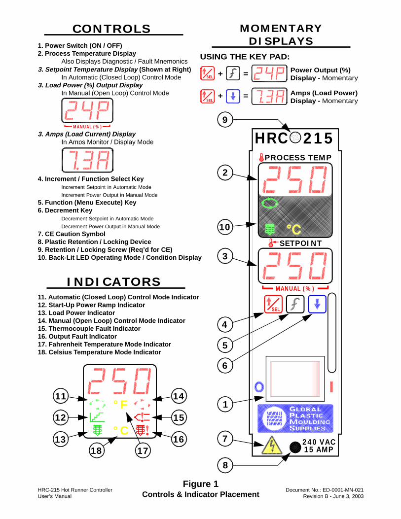
Figure 1Controls & Indicator Placement
2
10
3
4
5
6
1
7 240 VAC15 AMP
MANUAL (%)
SETPOINT
PROCESS TEMP
HRC 215
SEL
9
8
14
15°F
°C
11
12
1318 17
16
1. Power Switch (ON / OFF)2. Process Temperature Display
Also Displays Diagnostic / Fault Mnemonics
CONTROLS
INDICATORS11. Automatic (Closed Loop) Control Mode Indicator12. Start-Up Power Ramp Indicator13. Load Power Indicator14. Manual (Open Loop) Control Mode Indicator15. Thermocouple Fault Indicator16. Output Fault Indicator17. Fahrenheit Temperature Mode Indicator18. Celsius Temperature Mode Indicator
4. Increment / Function Select KeyIncrement Setpoint in Automatic Mode
Increment Power Output in Manual Mode
5. Function (Menu Execute) Key6. Decrement Key
Decrement Setpoint in Automatic Mode
Decrement Power Output in Manual Mode
7. CE Caution Symbol8. Plastic Retention / Locking Device9. Retention / Locking Screw (Req’d for CE)10. Back-Lit LED Operating Mode / Condition Display
3. Setpoint Temperature Display (Shown at Right)In Automatic (Closed Loop) Control Mode
3. Load Power (%) Output DisplayIn Manual (Open Loop) Control Mode
3. Amps (Load Current) DisplayIn Amps Monitor / Display Mode
MANUAL (%)
MOMENTARYDISPLAYS
USING THE KEY PAD:
SEL
SEL
Power Output (%)Display - Momentary
Amps (Load Power)Display - Momentary
+ =
+ =
HRC-215 Hot Runner Controller Document No.: ED-0001-MN-021-F User’s Manual June 1, 2006
INSPECTION After removing the HRC temperature controller from the shipping container immediately inspect the unit for damage resulting from mishandling in shipping. Inspect for loose components and mechanical damage such as bent sheet metal, marred front panel screen, etc. Remove the spare ABC15 fuses, locking screw and mainframe zone edge connector contact (required for anti-arc circuit) and save them for later use. Note: If the unit appears damaged or the container is missing components, contact your sales representative immediately! Use or modification of the controller or its packaging will decrease the likelihood of freight claim reimbursement. INSTALLATION
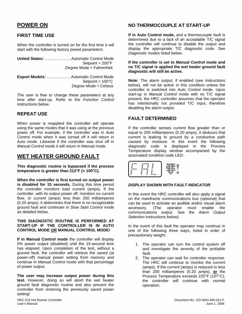
THIS HRC-215 IS EQUIPPED WITH A HIGH VOLTAGE ANTI-ARC CIRCUIT! AND IS ENABLED – TO PREVENT ELECTRICAL DAMAGE TO THE CONTROLLER IF ACCIDENTALLY REMOVED FROM THE MAINFRAME WITH POWER APPLIED. The controller WILL NOT apply power to the load unless mainframe zone edge connector contact #3 is installed. Inspect each mainframe zone edge connector for the required contact. If the contact is not already installed remove the mainframe rear cover (refer to manufacturer instructions) and install the contact supplied with the HRC. (Insure contact is locked in the connector by gently pushing on it from the front.)
Step 1: Verify installation Step 2: If not, install of contact. provided contact
Note that the contact itself completes the triac gate (drive) circuit. No wiring, or wire connection, is required to the #3 edge connector contact. The anti-arc circuit can be disabled by installing a #22-28 AWG wire jumper into the printed circuit board jumper position P5. (Soldering is required. See Fig. 2, Component Layout.) It is highly recommended that the anti-arc circuit not be disabled in this manner! If the controller is inadvertently installed or removed from the mainframe under power it will suffer severe damage, and possibly be destroyed. The user is encouraged to take advantage of this protective feature.
WARNING! THE CONTROL SYSTEM MAINFRAME MAIN POWER DISCONNECT MUST BE IN THE “OFF” POSITION BEFORE INSERTING OR REMOVING CONTROL MODULES TO PREVENT OPERATOR INJURY AND DAMAGE TO CONTROL SYSTEM COMPONENTS! Check the controller red power switch (Fig. 1 Item #1) insuring that it is in the “Off” (O) position. Pull the plunger of the black locking device (Fig. 1 Item #8) back into the “out” position. Align the controller PC board top and bottom rear corners with the respective card guide rails in a mainframe control zone. Slide the controller into the frame, keeping it parallel with the frame surfaces, until it meets resistance of the edge card connector. Place thumbs on the upper and lower right corners of the controller faceplate and firmly press it into the mainframe until the backside of the faceplate meets the frame. Gently push the plunger of the black locking device into its locked position. Note: For CE compliance it is necessary to install the supplied retention / locking screw (Fig. 1 Item #9) through the controller into the mainframe. This is to prevent inadvertent controller removal while the mainframe system is under power.
OPERATION Refer to Figure 1 to become oriented with the controller displays, indicators and user controls. The following control events are listed in order of priority.
HRC-215 Hot Runner Controller Document No.: ED-0001-MN-021-F User’s Manual June 1, 2006
POWER ON FIRST TIME USE When the controller is turned on for the first time it will start with the following factory preset parameters: United States: ……...…….…. Automatic Control Mode Setpoint = 200°F Degree Mode = Fahrenheit Export Models: ……….…….. Automatic Control Mode Setpoint = 100°C Degree Mode = Celsius The user is free to change these parameters at any time after start-up. Refer to the Function Control instructions below. REPEAT USE When power is reapplied the controller will operate using the same modes that it was using at the previous power off. For example, if the controller was in Auto Control mode when it was turned off it will return in Auto mode. Likewise if the controller was shut off in Manual Control mode it will return in Manual mode. WET HEATER GROUND FAULT This diagnostic routine is bypassed if the process temperature is greater than 212°F (> 100°C). When the controller is first turned on output power is disabled for 15 seconds. During this time period the controller monitors load current (amps). If the controller, with its output power off, monitors no current flow, or current (amps) less than 200 milliamperes (0.20 amps), it determines that there is no recognizable ground fault and continues in Slow Start Control mode as detailed below. THIS DIAGNOSTIC ROUTINE IS PERFORMED AT START-UP IF THE CONTROLLER IS IN AUTO CONTROL MODE OR MANUAL CONTROL MODE! If in Manual Control mode the controller will display 0% power output (disabled) until the 15-second time has elapsed. Upon completion of the test, without a ground fault, the controller will retrieve the saved (at power-off) manual power setting from memory and continue in Manual Control mode with that percentage of power output. The user may increase output power during this test. However, doing so will abort the wet heater ground fault diagnostic routine and also prevent the controller from restoring the previously saved power setting!
NO THERMOCOUPLE AT START-UP If in Auto Control mode, and a thermocouple fault is determined due to a lack of an acceptable T/C signal the controller will continue to disable the output and display the appropriate T/C diagnostic code. See Diagnostic modes listed below. If the controller is set to Manual Control mode and no T/C signal is applied the wet heater ground fault diagnostic will still be active. Note: The alarm output, if enabled (see instructions below), will not be active in this condition unless the controller is switched into Auto Control mode. Upon start-up in Manual Control mode with no T/C signal present, the HRC controller assumes that the operator has intentionally not provided T/C input, therefore disabling the alarm output. FAULT DETERMINED If the controller senses current flow greater than or equal to 200 milliamperes (0.20 amps), it deduces that current is leaking to ground by a conductive path caused by moisture. In this event the following diagnostic code is displayed in the Process Temperature display window accompanied by the associated condition code LED:
DISPLAY SHOWN WITH FAULT INDICATOR In this event the HRC controller will also apply a signal on the mainframe communications bus (optional) that can be used to activate an audible and/or visual alarm accessory. (The operator must enable the communications output. See the Alarm Output Selection instructions below). In the event of this fault the operator may continue in one of the following three ways, listed in order of precautionary weight:
1. The operator can turn the control system off and investigate the severity of the probable fault.
2. The operator can wait for controller response. The HRC will continue to monitor the current (amps). If the current (amps) is reduced to less than 200 milliamperes (0.20 amps), or the Process Temperature exceeds 225°F (107°C), the controller will continue with normal operation.
HRC-215 Hot Runner Controller Document No.: ED-0001-MN-021-F User’s Manual June 1, 2006
If in Auto Control mode and current flow (amps) is decreased, and the temperature is lower than 225°F (107°C), it enters the Slow Start Control mode. If in Manual Control mode the controller will stay at 0% output power (inhibited) until the current is reduced or the temperature exceeds 225°F (107°C). In either case the fault will be cleared and the previous power setting will be restored, and the module will operate normally. If in Manual Control mode and no thermocouple signal is present the wet heater fault will continue until current flow (amps) stops, regardless of the load temperature. (Without T/C feedback the HRC has no way to determine load temperature.)
3. The operator can override the diagnostic routine. The controller must be set in Manual Control mode and power must be manually increased from 0%. (See Function Control instructions below to change control modes).
SLOW START CONTROL For Wet Heater Bake-Out Disabled If In Manual Control Mode
SLOW START MODE INDICATOR Upon start-up, the controller always enters Slow Start Control mode when all of the following conditions have been met:
1. The controller is set for Auto Control operation. 2. The process temperature is less than 212°F (<
100°C). 3. The wet heater diagnostic is completed without
a fault condition. Slow Start control utilizes a special power control routine designed to avoid heater destruction due to conductive paths to ground caused by moisture. While maintaining a low power setting, the HRC controller ramps the load temperature to 212°F (100°C) at a 1-degree per second rate of rise. When 212°F (100°C) has been achieved the controller quickly reduces power to slow the temperature rise for a period of 1 minute. Upon completion the controller will continue to drive the process temperature to the setpoint. To disable Slow Start Control the operator may perform one of the following tasks:
1. Using the Function Control selector key, the Slow Start function can be called from the menu and disabled by depressing the Select key.
2. The operator can switch the controller into Manual Control mode and adjust the output power to drive the temperature above 212°F (100°C), and then switch the controller back into Auto Control mode to continue normal operation. The Function Control sequences required for the above action are detailed in a section below.
AUTOMATIC CONTROL MODE Refer to the Function Control instructions below to select Auto Control mode. In Automatic (Auto) Control mode the HRC controller uses a PID algorithm to determine the required output power to hold the Process Temperature equal to the Setpoint Temperature. This type of control is a “closed loop” system and requires a thermocouple feedback signal. The Closed Loop mode indicator indicates this control mode:
CLOSED LOOP MODE INDICATOR The Setpoint Temperature is determined by the operator and indicated on the lower LED display:
SETPOINT DISPLAY The Setpoint can be easily adjusted up or down at any time during Auto Control mode operation by depressing the Increment / Decrement keys of the key pad:
The keys can be pressed and released one unit digit at a time, or for larger changes, the key can be held down for continuous change. In this mode the speed at which the setting is changed is ramped from slow to very fast. For example, the longer the key is held in the faster the numbers change. AUTOMATIC PID TUNING The HRC controller uses a PID (three term) control algorithm to determine the required load power needed to reach and maintain the Setpoint Temperature. Every thermal system has different characteristics. To accurately control each dynamic system the HRC must “learn” each load’s characteristics individually. In addition, every system’s variables change with
HRC-215 Hot Runner Controller Document No.: ED-0001-MN-021-F User’s Manual June 1, 2006
temperature changes. For example, a load’s set of control variables may be different at 200° than at 350°. To accomplish “learning” each load’s variables and to eliminate complex operator intervention the HRC controller automatically enters a “tuning” routine when the Process Temperature reaches a point less than or equal to 80°F (45°C) below Setpoint Temperature. The controller will go through a sequence of applying different levels of power to monitor load response. The HRC takes the information it “learned” and adjusts the PID control variables accordingly. Note: The HRC automatically calls this tuning routine at power-on regardless of the current Process Temperature. The controller also repeats this tuning process when the operator makes a Setpoint Temperature change greater than or equal to 100°F (55°C). The controller will not tune if it is turned on with a process temperature greater than the setpoint. MANUAL CONTROL MODE Refer to the Function Control instructions below to select Manual Control mode. In Manual Control mode the HRC controller regulates load power determined by the user selected Power Output setting. The power delivered is constant and will only change with user input. This type of control is an “open loop” system and requires no thermocouple feedback signal. The Open Loop mode indicator indicates this control mode:
OPEN LOOP MODE INDICATOR The Power Output setting is determined by the operator and indicated on the lower LED display:
POWER OUT DISPLAY The Power Output setting can be easily adjusted up or down at any time during Manual Control mode operation by depressing the Increment / Decrement keys of the key pad:
The keys can be pressed and released one unit digit at a time, or for larger changes, the key can be held down for continuous change. In this mode the speed at which the setting is changed is ramped from slow to very fast.
For example, the longer the key is held in, the faster the numbers change. POWER TRANSFER FROM AUTO MODE When the HRC controller is operating in Auto Control mode it records the average power setting required to maintain Setpoint Temperature. When the operator switches from Auto Control mode to Manual Control mode this power setting is automatically set for use. The operator is free to change the power setting at any time following the control mode transition. This output power level will most likely not be able to hold the former setpoint but it will bring the load to a constant temperature that may or may not be close to the former setpoint value. As the controller is working in Auto Control mode it is continually changing output power to maintain Setpoint Temperature. The continuous changes are required to keep up with process upsets to the thermal system. CURRENT (AMPS) MONITOR MODE Refer to the Function Control instructions below to select Current (Amps) Monitor mode. Whether operating in Auto Control mode or Manual Control mode the HRC allows the operator to continuously monitor load current (amps). The monitored value is the average current (amps) being delivered to the load. Because the HRC applies power to the load using a pattern of voltage pulses, true instantaneous current would be rapidly changing from second to second and would be difficult for the operator to interpret. The displayed average value is a much more useful quantity to the user.
CURRENT (AMPS) DISPLAY Additionally, the operator may momentarily view load current (amps) by pressing and holding the Increment Key and the Decrement Key at the same time. (Refer to the User Interface section below). LOAD POWER INDICATION In either Auto Control mode or Manual Control mode power being delivered to the load is indicated:
LOAD POWER INDICATOR The indicator flashes concurrently with the firing (closing) of the load power output device (triac). Power is delivered by time proportioned preset patterns. The time interval between pulses is proportional to the power requirement. The lower the power, the slower
HRC-215 Hot Runner Controller Document No.: ED-0001-MN-021-F User’s Manual June 1, 2006
the flash. Conversely, the higher the power the faster the flash. For example, at maximum power output (99%) the LED indicator will be on continuously. With power off (0%) the indicator will never turn on. WARNING! The Load Power Indicator lights when the triac is turned on by the controller’s MCU and is independent of voltage applied to the load! The indicator not being illuminated is not a guarantee that the control device (triac) is open. The HRC controller will recognize a shorted triac fault (See Diagnostic instructions below) and will notify the operator. But, in this situation, the HRC controller can not open or control the failed triac. For this reason it is imperative that under a load fault condition that the operator switch the controller power disconnect switch (Fig. 1 Item #1) and also the mainframe system disconnect to the “OFF” positions before removing a controller or interconnect cabling. USER INTERFACE The user makes various control mode and setting changes using the three momentary switch keypad on the controller front panel (Fig. 1 Item #4, 5 & 6). The operator simply pushes and holds the desired key until the variable change is recognized on the appropriate display. For multiple keystrokes of the same key the user can hold the key in the closed position rather than entering several individual closures. In this event the controller continuously repeats the function and the input becomes more rapid the longer the key is held in. It may be noticed that the HRC controller does not accept quick individual key entries. The operating program has a switch closure delay time requirement that must be met before the controller will accept input as a good key and react accordingly. This precautionary measure is included to prevent the controller from reacting to environmental noise. CAUTION: The operator should not use anything other than their finger to actuate a keypad key! The use of pens, pencils, screwdrivers or other tools will damage the keyboard assembly. Such damage is considered abuse and is not included under warranty coverage. The individual keys are described as follows:
INCREMENT / MODE SELECT KEY This is a dual function key.
The INCREMENT function is automatically active (Select inactive) during normal Auto and Manual Control modes and is used to increase the Setpoint Temperature and Power Output level respectively. The SELECT function is automatically active (Increment inactive) during Function Control mode and is used by the operator to Select, or activate, different control, display and operating modes. Function Control operations are detailed below.
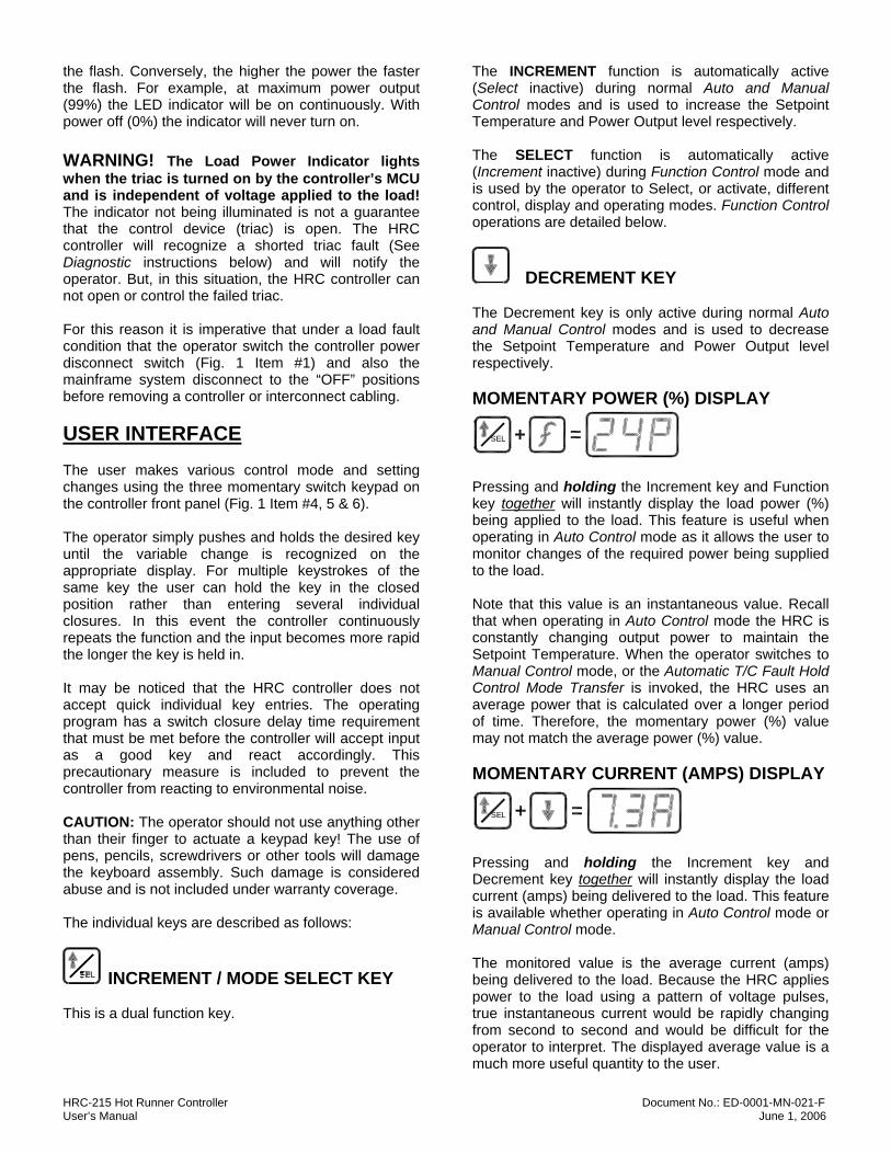
DECREMENT KEY The Decrement key is only active during normal Auto and Manual Control modes and is used to decrease the Setpoint Temperature and Power Output level respectively. MOMENTARY POWER (%) DISPLAY
SEL
Pressing and holding the Increment key and Function key together will instantly display the load power (%) being applied to the load. This feature is useful when operating in Auto Control mode as it allows the user to monitor changes of the required power being supplied to the load. Note that this value is an instantaneous value. Recall that when operating in Auto Control mode the HRC is constantly changing output power to maintain the Setpoint Temperature. When the operator switches to Manual Control mode, or the Automatic T/C Fault Hold Control Mode Transfer is invoked, the HRC uses an average power that is calculated over a longer period of time. Therefore, the momentary power (%) value may not match the average power (%) value. MOMENTARY CURRENT (AMPS) DISPLAY
SEL
Pressing and holding the Increment key and Decrement key together will instantly display the load current (amps) being delivered to the load. This feature is available whether operating in Auto Control mode or Manual Control mode. The monitored value is the average current (amps) being delivered to the load. Because the HRC applies power to the load using a pattern of voltage pulses, true instantaneous current would be rapidly changing from second to second and would be difficult for the operator to interpret. The displayed average value is a much more useful quantity to the user.
HRC-215 Hot Runner Controller Document No.: ED-0001-MN-021-F User’s Manual June 1, 2006
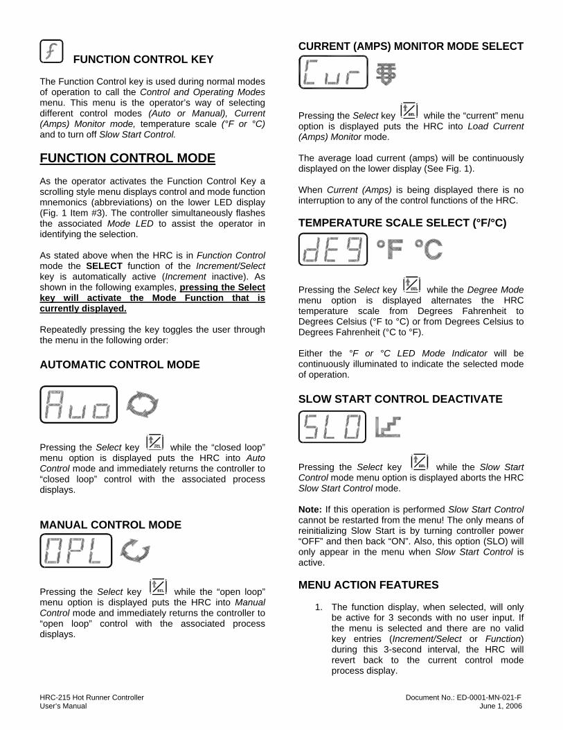
FUNCTION CONTROL KEY The Function Control key is used during normal modes of operation to call the Control and Operating Modes menu. This menu is the operator’s way of selecting different control modes (Auto or Manual), Current (Amps) Monitor mode, temperature scale (°F or °C) and to turn off Slow Start Control. FUNCTION CONTROL MODE As the operator activates the Function Control Key a scrolling style menu displays control and mode function mnemonics (abbreviations) on the lower LED display (Fig. 1 Item #3). The controller simultaneously flashes the associated Mode LED to assist the operator in identifying the selection. As stated above when the HRC is in Function Control mode the SELECT function of the Increment/Select key is automatically active (Increment inactive). As shown in the following examples, pressing the Select key will activate the Mode Function that is currently displayed. Repeatedly pressing the key toggles the user through the menu in the following order: AUTOMATIC CONTROL MODE
Pressing the Select key while the “closed loop” menu option is displayed puts the HRC into Auto Control mode and immediately returns the controller to “closed loop” control with the associated process displays. MANUAL CONTROL MODE
Pressing the Select key while the “open loop” menu option is displayed puts the HRC into Manual Control mode and immediately returns the controller to “open loop” control with the associated process displays.
CURRENT (AMPS) MONITOR MODE SELECT
Pressing the Select key while the “current” menu option is displayed puts the HRC into Load Current (Amps) Monitor mode. The average load current (amps) will be continuously displayed on the lower display (See Fig. 1). When Current (Amps) is being displayed there is no interruption to any of the control functions of the HRC. TEMPERATURE SCALE SELECT (°F/°C)
Pressing the Select key while the Degree Mode menu option is displayed alternates the HRC temperature scale from Degrees Fahrenheit to Degrees Celsius (°F to °C) or from Degrees Celsius to Degrees Fahrenheit (°C to °F). Either the °F or °C LED Mode Indicator will be continuously illuminated to indicate the selected mode of operation. SLOW START CONTROL DEACTIVATE
Pressing the Select key while the Slow Start Control mode menu option is displayed aborts the HRC Slow Start Control mode. Note: If this operation is performed Slow Start Control cannot be restarted from the menu! The only means of reinitializing Slow Start is by turning controller power “OFF” and then back “ON”. Also, this option (SLO) will only appear in the menu when Slow Start Control is active. MENU ACTION FEATURES
1. The function display, when selected, will only be active for 3 seconds with no user input. If the menu is selected and there are no valid key entries (Increment/Select or Function) during this 3-second interval, the HRC will revert back to the current control mode process display.
HRC-215 Hot Runner Controller Document No.: ED-0001-MN-021-F User’s Manual June 1, 2006
2. The Decrement key is totally inactive during Function Control / Menu Action. Therefore, if the key is pressed the HRC will not respond.
3. When in Current (Amps) Monitor mode, both the Increment and Decrement keys are totally inactive.
4. The temperature control process is not interrupted during Function Control activity. The HRC continues “back ground” control, whether in Auto or Manual Control mode. It does not suspend control activity while waiting for user input.
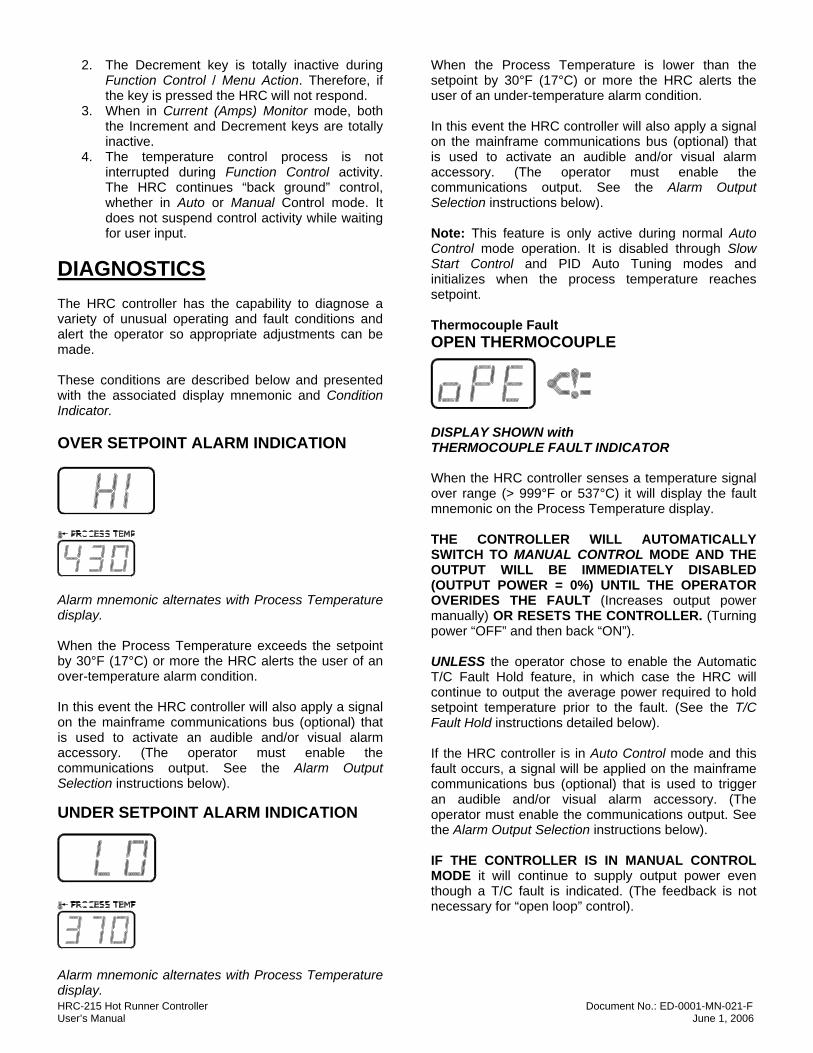
DIAGNOSTICS The HRC controller has the capability to diagnose a variety of unusual operating and fault conditions and alert the operator so appropriate adjustments can be made. These conditions are described below and presented with the associated display mnemonic and Condition Indicator. OVER SETPOINT ALARM INDICATION
Alarm mnemonic alternates with Process Temperature display. When the Process Temperature exceeds the setpoint by 30°F (17°C) or more the HRC alerts the user of an over-temperature alarm condition. In this event the HRC controller will also apply a signal on the mainframe communications bus (optional) that is used to activate an audible and/or visual alarm accessory. (The operator must enable the communications output. See the Alarm Output Selection instructions below). UNDER SETPOINT ALARM INDICATION
Alarm mnemonic alternates with Process Temperature display.
When the Process Temperature is lower than the setpoint by 30°F (17°C) or more the HRC alerts the user of an under-temperature alarm condition. In this event the HRC controller will also apply a signal on the mainframe communications bus (optional) that is used to activate an audible and/or visual alarm accessory. (The operator must enable the communications output. See the Alarm Output Selection instructions below). Note: This feature is only active during normal Auto Control mode operation. It is disabled through Slow Start Control and PID Auto Tuning modes and initializes when the process temperature reaches setpoint. Thermocouple Fault OPEN THERMOCOUPLE
DISPLAY SHOWN with THERMOCOUPLE FAULT INDICATOR When the HRC controller senses a temperature signal over range (> 999°F or 537°C) it will display the fault mnemonic on the Process Temperature display. THE CONTROLLER WILL AUTOMATICALLY SWITCH TO MANUAL CONTROL MODE AND THE OUTPUT WILL BE IMMEDIATELY DISABLED (OUTPUT POWER = 0%) UNTIL THE OPERATOR OVERIDES THE FAULT (Increases output power manually) OR RESETS THE CONTROLLER. (Turning power “OFF” and then back “ON”). UNLESS the operator chose to enable the Automatic T/C Fault Hold feature, in which case the HRC will continue to output the average power required to hold setpoint temperature prior to the fault. (See the T/C Fault Hold instructions detailed below). If the HRC controller is in Auto Control mode and this fault occurs, a signal will be applied on the mainframe communications bus (optional) that is used to trigger an audible and/or visual alarm accessory. (The operator must enable the communications output. See the Alarm Output Selection instructions below). IF THE CONTROLLER IS IN MANUAL CONTROL MODE it will continue to supply output power even though a T/C fault is indicated. (The feedback is not necessary for “open loop” control).
HRC-215 Hot Runner Controller Document No.: ED-0001-MN-021-F User’s Manual June 1, 2006
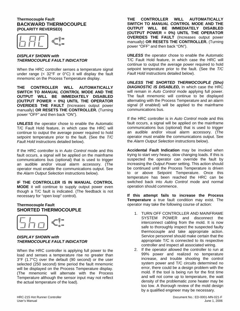
Thermocouple Fault BACKWARD THERMOCOUPLE (POLARITY REVERSED)
DISPLAY SHOWN with THERMOCOUPLE FAULT INDICATOR When the HRC controller senses a temperature signal under range (< 32°F or 0°C) it will display the fault mnemonic on the Process Temperature display. THE CONTROLLER WILL AUTOMATICALLY SWITCH TO MANUAL CONTROL MODE AND THE OUTPUT WILL BE IMMEDIATELY DISABLED (OUTPUT POWER = 0%) UNTIL THE OPERATOR OVERIDES THE FAULT (Increases output power manually) OR RESETS THE CONTROLLER. (Turning power “OFF” and then back “ON”). UNLESS the operator chose to enable the Automatic T/C Fault Hold feature, in which case the HRC will continue to output the average power required to hold setpoint temperature prior to the fault. (See the T/C Fault Hold instructions detailed below). If the HRC controller is in Auto Control mode and this fault occurs, a signal will be applied on the mainframe communications bus (optional) that is used to trigger an audible and/or visual alarm accessory. (The operator must enable the communications output. See the Alarm Output Selection instructions below). IF THE CONTROLLER IS IN MANUAL CONTROL MODE it will continue to supply output power even though a T/C fault is indicated. (The feedback is not necessary for “open loop” control). Thermocouple Fault SHORTED THERMOCOUPLE
DISPLAY SHOWN with THERMOCOUPLE FAULT INDICATOR When the HRC controller is applying full power to the load and senses a temperature rise no greater than 3°F (1.7°C) over the default (90 second) or the user selected (250 second) time period the fault mnemonic will be displayed on the Process Temperature display. (The mnemonic will alternate with the Process Temperature although the sensor input may not reflect the actual temperature of the load).
THE CONTROLLER WILL AUTOMATICALLY SWITCH TO MANUAL CONTROL MODE AND THE OUTPUT WILL BE IMMEDIATELY DISABLED (OUTPUT POWER = 0%) UNTIL THE OPERATOR OVERIDES THE FAULT (Increases output power manually) OR RESETS THE CONTROLLER. (Turning power “OFF” and then back “ON”). UNLESS the operator chose to enable the Automatic T/C Fault Hold feature, in which case the HRC will continue to output the average power required to hold setpoint temperature prior to the fault. (See the T/C Fault Hold instructions detailed below). UNLESS THE SHORTED THERMOCOUPLE (Sho) DIAGNOSTIC IS DISABLED, In which case the HRC will remain in Auto Control mode applying full power. The fault mnemonic will continue to be displayed alternating with the Process Temperature and an alarm signal (if enabled) will be applied to the mainframe communications bus. If the HRC controller is in Auto Control mode and this fault occurs, a signal will be applied on the mainframe communications bus (optional) that is used to trigger an audible and/or visual alarm accessory. (The operator must enable the communications output. See the Alarm Output Selection instructions below). Accidental Fault Indication may be invoked when trying to start very heavy, slow changing loads. If this is suspected the operator can override the fault by increasing the Output Power setting. This action should be continued until the Process Temperature is driven to or above Setpoint Temperature. Once this temperature has been reached the HRC can be switched back into Auto Control mode and normal operation should commence. If this attempt fails to increase the Process Temperature a true fault condition may exist. The operator may take the following course of action:
1. TURN OFF CONTROLLER AND MAINFRAME SYSTEM POWER and disconnect the interconnect cabling from the mold. It is now safe to thoroughly inspect the suspected faulty thermocouple and take appropriate action. Service personnel should make certain that the appropriate T/C is connected to its respective controller and inspect all associated wiring.
2. If the operator allowed the controller to run at 99% power and realized no temperature increase, and trouble shooting the control system power and T/C circuits determined no error, there could be a design problem with the mold. If the tool is being run for the first time and will not come up to temperature, the watt density of the problematic zone heater may be too low. A thorough review of the mold design by a qualified engineer may be necessary.
HRC-215 Hot Runner Controller Document No.: ED-0001-MN-021-F User’s Manual June 1, 2006
Additionally, low line voltage can lead to poor response from the heaters. Again, if no thermocouple errors are discovered, a full system analysis may need to be done by qualified personnel.
IF THE CONTROLLER IS IN MANUAL CONTROL MODE it will continue to supply output power even though a T/C fault is indicated. (The feedback is not necessary for “open loop” control). USER SELECTABLE SHORTED T/C SAMPLE TIME or DISABLE As stated above, accidental fault indication may be invoked when trying to start very heavy, slow changing loads. If this is suspected the operator can change the Shorted T/C diagnostic test sample time. As stated above, the HRC requires a temperature rise of 3°F (1.7°C) over a preset time period to not call a Sho fault. The factory default time is 90 seconds, but heavy thermal loads often require more time than this to register changes in temperature. If the user suspects such a load is being controlled the test time period may be changed to 250 seconds by activating the “Sho T/C LONG DELAY” DIP switch of SW4. (See Fig. 2). The switch bank SW4 must be set to the user’s requirements as detailed in Figure 2. If the user continues to experience errant fault recognition the Shorted T/C diagnostic can be disabled. In the same manner as enabling the Sho T/C long delay, the “Sho T/C *OFF*” DIP switch of SW4 must be activated as detailed in Figure 2. CAUTION: IT IS STRONGLY RECOMMENDED THAT SHORTED T/C DIAGNOSTIC NOT BE DISABLED! Under this condition the HRC will continue to apply full (99%) output power to a load that may have a faulty thermocouple. Under these circumstances THE PROCESS TEMPERATURE DISPLAY IS NOT REPRESENTATIVE OF THE TRUE TEMPERATURE OF THE LOAD. The heater may be creating an extremely high temperature that could create dangerous and volatile conditions. To change the printed circuit board SW4 Sho DIP switches it will be necessary to turn the HRC controller and mainframe power **OFF** and remove the controller from the mainframe.
WARNING! THE CONTROL SYSTEM MAINFRAME MAIN POWER DISCONNECT MUST BE IN THE “OFF” POSITION BEFORE INSERTING OR REMOVING CONTROL MODULES TO PREVENT OPERATOR INJURY AND DAMAGE TO CONTROL SYSTEM COMPONENTS!
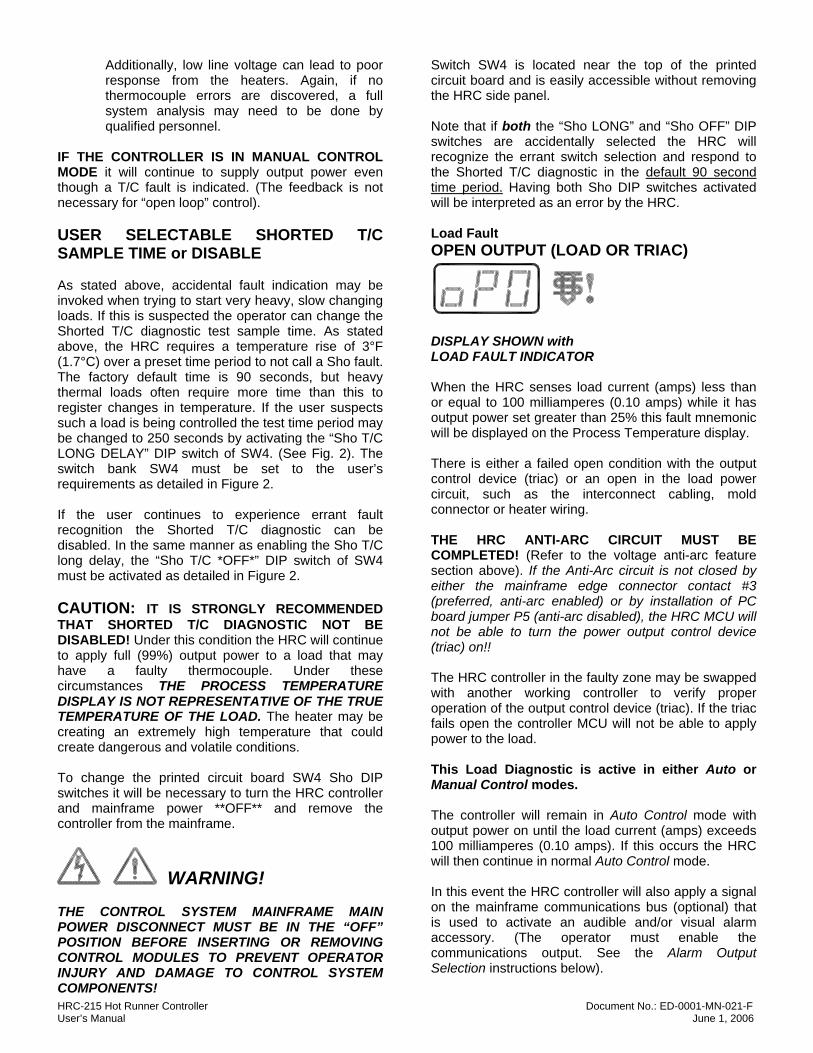
Switch SW4 is located near the top of the printed circuit board and is easily accessible without removing the HRC side panel. Note that if both the “Sho LONG” and “Sho OFF” DIP switches are accidentally selected the HRC will recognize the errant switch selection and respond to the Shorted T/C diagnostic in the default 90 second time period. Having both Sho DIP switches activated will be interpreted as an error by the HRC. Load Fault OPEN OUTPUT (LOAD OR TRIAC)
DISPLAY SHOWN with LOAD FAULT INDICATOR When the HRC senses load current (amps) less than or equal to 100 milliamperes (0.10 amps) while it has output power set greater than 25% this fault mnemonic will be displayed on the Process Temperature display. There is either a failed open condition with the output control device (triac) or an open in the load power circuit, such as the interconnect cabling, mold connector or heater wiring. THE HRC ANTI-ARC CIRCUIT MUST BE COMPLETED! (Refer to the voltage anti-arc feature section above). If the Anti-Arc circuit is not closed by either the mainframe edge connector contact #3 (preferred, anti-arc enabled) or by installation of PC board jumper P5 (anti-arc disabled), the HRC MCU will not be able to turn the power output control device (triac) on!! The HRC controller in the faulty zone may be swapped with another working controller to verify proper operation of the output control device (triac). If the triac fails open the controller MCU will not be able to apply power to the load. This Load Diagnostic is active in either Auto or Manual Control modes. The controller will remain in Auto Control mode with output power on until the load current (amps) exceeds 100 milliamperes (0.10 amps). If this occurs the HRC will then continue in normal Auto Control mode. In this event the HRC controller will also apply a signal on the mainframe communications bus (optional) that is used to activate an audible and/or visual alarm accessory. (The operator must enable the communications output. See the Alarm Output Selection instructions below).
HRC-215 Hot Runner Controller Document No.: ED-0001-MN-021-F User’s Manual June 1, 2006
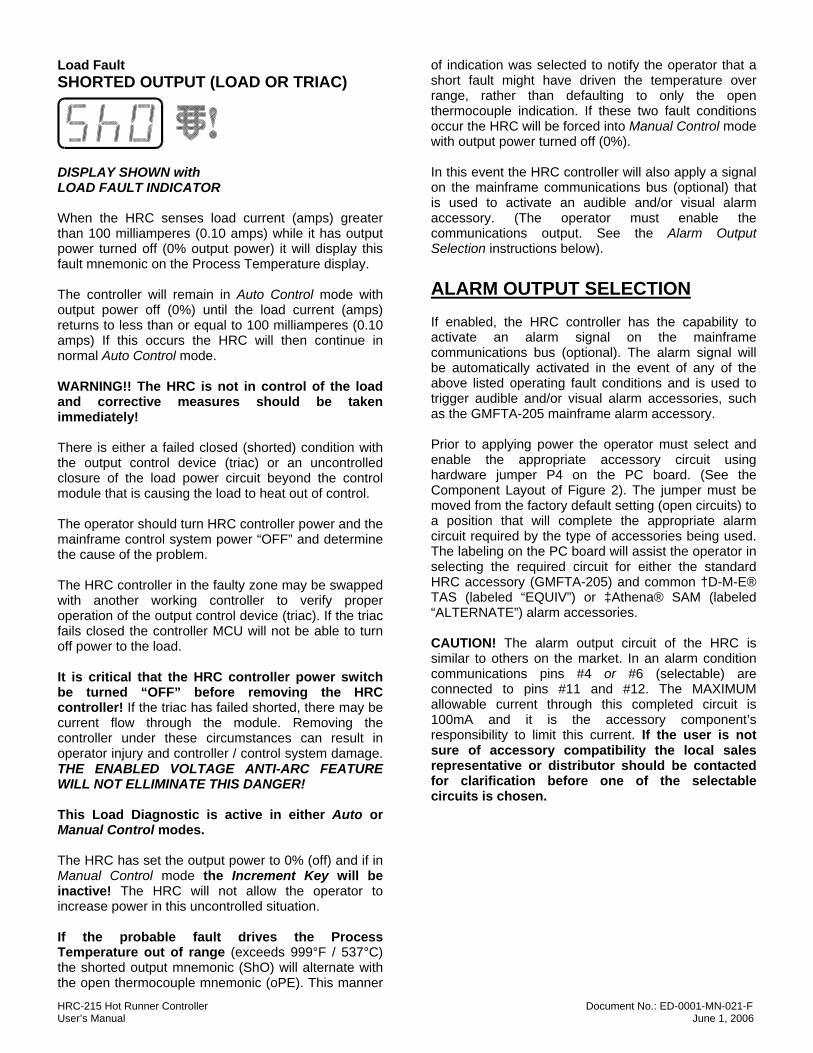
Load Fault SHORTED OUTPUT (LOAD OR TRIAC)
DISPLAY SHOWN with LOAD FAULT INDICATOR When the HRC senses load current (amps) greater than 100 milliamperes (0.10 amps) while it has output power turned off (0% output power) it will display this fault mnemonic on the Process Temperature display. The controller will remain in Auto Control mode with output power off (0%) until the load current (amps) returns to less than or equal to 100 milliamperes (0.10 amps) If this occurs the HRC will then continue in normal Auto Control mode. WARNING!! The HRC is not in control of the load and corrective measures should be taken immediately! There is either a failed closed (shorted) condition with the output control device (triac) or an uncontrolled closure of the load power circuit beyond the control module that is causing the load to heat out of control. The operator should turn HRC controller power and the mainframe control system power “OFF” and determine the cause of the problem. The HRC controller in the faulty zone may be swapped with another working controller to verify proper operation of the output control device (triac). If the triac fails closed the controller MCU will not be able to turn off power to the load. It is critical that the HRC controller power switch be turned “OFF” before removing the HRC controller! If the triac has failed shorted, there may be current flow through the module. Removing the controller under these circumstances can result in operator injury and controller / control system damage. THE ENABLED VOLTAGE ANTI-ARC FEATURE WILL NOT ELLIMINATE THIS DANGER! This Load Diagnostic is active in either Auto or Manual Control modes. The HRC has set the output power to 0% (off) and if in Manual Control mode the Increment Key will be inactive! The HRC will not allow the operator to increase power in this uncontrolled situation. If the probable fault drives the Process Temperature out of range (exceeds 999°F / 537°C) the shorted output mnemonic (ShO) will alternate with the open thermocouple mnemonic (oPE). This manner
of indication was selected to notify the operator that a short fault might have driven the temperature over range, rather than defaulting to only the open thermocouple indication. If these two fault conditions occur the HRC will be forced into Manual Control mode with output power turned off (0%). In this event the HRC controller will also apply a signal on the mainframe communications bus (optional) that is used to activate an audible and/or visual alarm accessory. (The operator must enable the communications output. See the Alarm Output Selection instructions below). ALARM OUTPUT SELECTION If enabled, the HRC controller has the capability to activate an alarm signal on the mainframe communications bus (optional). The alarm signal will be automatically activated in the event of any of the above listed operating fault conditions and is used to trigger audible and/or visual alarm accessories, such as the GMFTA-205 mainframe alarm accessory. Prior to applying power the operator must select and enable the appropriate accessory circuit using hardware jumper P4 on the PC board. (See the Component Layout of Figure 2). The jumper must be moved from the factory default setting (open circuits) to a position that will complete the appropriate alarm circuit required by the type of accessories being used. The labeling on the PC board will assist the operator in selecting the required circuit for either the standard HRC accessory (GMFTA-205) and common †D-M-E® TAS (labeled “EQUIV”) or ‡Athena® SAM (labeled “ALTERNATE”) alarm accessories. CAUTION! The alarm output circuit of the HRC is similar to others on the market. In an alarm condition communications pins #4 or #6 (selectable) are connected to pins #11 and #12. The MAXIMUM allowable current through this completed circuit is 100mA and it is the accessory component’s responsibility to limit this current. If the user is not sure of accessory compatibility the local sales representative or distributor should be contacted for clarification before one of the selectable circuits is chosen.
HRC-215 Hot Runner Controller Document No.: ED-0001-MN-021-F User’s Manual June 1, 2006
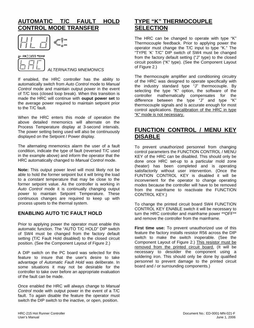
AUTOMATIC T/C FAULT HOLD CONTROL MODE TRANSFER
ALTERNATING MNEMONICS If enabled, the HRC controller has the ability to automatically switch from Auto Control mode to Manual Control mode and maintain output power in the event of T/C loss (closed loop break). When this transition is made the HRC will continue with ouput power set to the average power required to maintain setpoint prior to the T/C fault. When the HRC enters this mode of operation the above detailed mnemonics will alternate on the Process Temperature display at 3-second intervals. The power setting being used will also be continuously displayed on the Setpoint / Power display. The alternating mnemonics alarm the user of a fault condition, indicate the type of fault (reversed T/C used in the example above) and inform the operator that the HRC automatically changed to Manual Control mode. Note: This output power level will most likely not be able to hold the former setpoint but it will bring the load to a constant temperature that may be close to the former setpoint value. As the controller is working in Auto Control mode it is continually changing output power to maintain Setpoint Temperature. These continuous changes are required to keep up with process upsets to the thermal system. ENABLING AUTO T/C FAULT HOLD Prior to applying power the operator must enable this automatic function. The “AUTO T/C HOLD” DIP switch of SW4 must be changed from the factory default setting (T/C Fault Hold disabled) to the closed circuit position. (See the Component Layout of Figure 2.) A DIP switch on the PC board was selected for this feature to insure that the user’s desire to take advantage of Automatic Fault Hold was deliberate. In some situations it may not be desirable for the controller to take over before an appropriate evaluation of the fault can be made. Once enabled the HRC will always change to Manual Control mode with output power in the event of a T/C fault. To again disable the feature the operator must switch the DIP switch to the inactive, or open, position.
TYPE “K” THERMOCOUPLE SELECTION The HRC can be changed to operate with type “K” Thermocouple feedback. Prior to applying power the operator must change the T/C input to type “K.” The “TYPE ‘K’ T/C” DIP switch of SW4 must be changed from the factory default setting (“J” type) to the closed circuit position (“K” type). (See the Component Layout of Figure 2.) The thermocouple amplifier and conditioning circuitry of the HRC was designed to operate specifically with the industry standard type “J” thermocouple. By selecting the type “K” option, the software of the controller mathematically compensates for the difference between the type “J” and type “K” thermocouple signals and is accurate enough for most control applications. Recalibration of the HRC in type “K” mode is not necessary. FUNCTION CONTROL / MENU KEY DISABLE To prevent unauthorized personnel from changing control parameters the FUNCTION CONTROL / MENU KEY of the HRC can be disabled. This should only be done once HRC set-up to a particular mold zone (heater) has been completed and is operating satisfactorily without user intervention. (Once the FUNTION CONTROL KEY is disabled it will be inconvenient for the operator to change operating modes because the controller will have to be removed from the mainframe to reactivate the FUNCTION CONTROL KEY.) To change the printed circuit board SW4 FUNCTION CONTROL KEY ENABLE switch it will be necessary to turn the HRC controller and mainframe power **OFF** and remove the controller from the mainframe. First time use: To prevent unauthorized use of this feature the factory installs resistor R56 across the DIP switch to make the switch inoperable. (See the Component Layout of Figure 2.) This resistor must be removed from the printed circuit board. (It will be necessary to desolder the component using a soldering iron. This should only be done by qualified personnel to prevent damage to the printed circuit board and / or surrounding components.)
HRC-215 Hot Runner Controller Document No.: ED-0001-MN-021-F User’s Manual June 1, 2006
Once the resistor has been removed, the “FUNCTION KEY ENABLE” DIP switch of SW4 will be operational. To disable the FUNCTION CONTROL KEY, the DIP switch should be down, or in the open position. To enable, or reactivate, the FUNTION CONTROL KEY, the DIP switch should be up, or in the closed position. MAINTENANCE The HRC controller requires very little maintenance for continuous, reliable and accurate operation. Depending on the atmosphere of the facility it may be appropriate to periodically clean the main printed circuit board assembly. This should only require blowing off dust and debris using clean and dry compressed air. If the printed circuit board has been soiled and the air is not sufficient it is acceptable to clean the board, components and component leads using ISOPROPYL ALCHOHOL only. Be sure that the board and components are completely dry before reapplying power to prevent unsafe and damaging short circuits. If the faceplate / keyboard assembly needs to be cleaned use only a DAMP RAG AND MILD DETERGENT. Gently rub the polycarbonate overlay to remove any oil and debris. Be sure that all components are completely dry before reapplying power to prevent unsafe and damaging short circuits. CALIBRATION The manufacturer recommends that the HRC controller be calibrated every 12 months to maintain accuracy and to perform within the operating specifications. Arrangements can be made with a sales representative to have the HRC controllers calibrated using standards and equipment traceable to each region’s respective governing agencies. TEMPERATURE CALIBRATION There are two temperature calibration potentiometers on the main printed circuit board (See Fig. 2). Pot R27 is used to set the low end of the temperature scale and pot R19 is used to set the high end of the scale. For the highest accuracy it is recommended to calibrate the HRC controller in the degrees Fahrenheit (°F) temperature scale. A “J” type thermocouple calibrator (millivolt source) is required to calibrate the HRC. The simulated T/C signal must be applied directly to the controller edge card “finger” contacts. (Fig. 2; T/C polarity is critical).
TYPE “J” T/C TEMPERATURE CALIBRATION STEP 1: With the thermocouple input set to 200°F (93°C). Slowly turn Pot R27 (Low Cal) as required until the HRC Process Temperature display reads the same as the simulator (200°F / 93°C). STEP 2: Change the calibrator input to 800°F (427°C). Slowly turn Pot R19 (High Cal) as required until the HRC Process Temperature display reads the same as the simulator (800°F / 427°C). Turn the potentiometers slowly and STOP when resistance is met to avoid unintentional physical damage to the components! STEP 3: Repeat steps 1-2 as many times as necessary until the low end and high end displays consistently match the simulator. Note: It should only be necessary to repeat these steps 2-3 times to calibrate the HRC. If calibration has not been achieved after several attempts there may be component malfunctions that need serviced. Contact your local sales representative or distributor to make arrangements to return the controller for repair by an authorized technician. TYPE “K” T/C TEMPERATURE CALIBRATION It is not necessary to recalibrate the HRC using a type “K” T/C input to operate properly in type “K” Thermocouple input mode. Insure that the controller is in calibration using the standard type “J” T/C input.
HRC-215 Hot Runner Controller Document No.: ED-0001-MN-021-F User’s Manual June 1, 2006
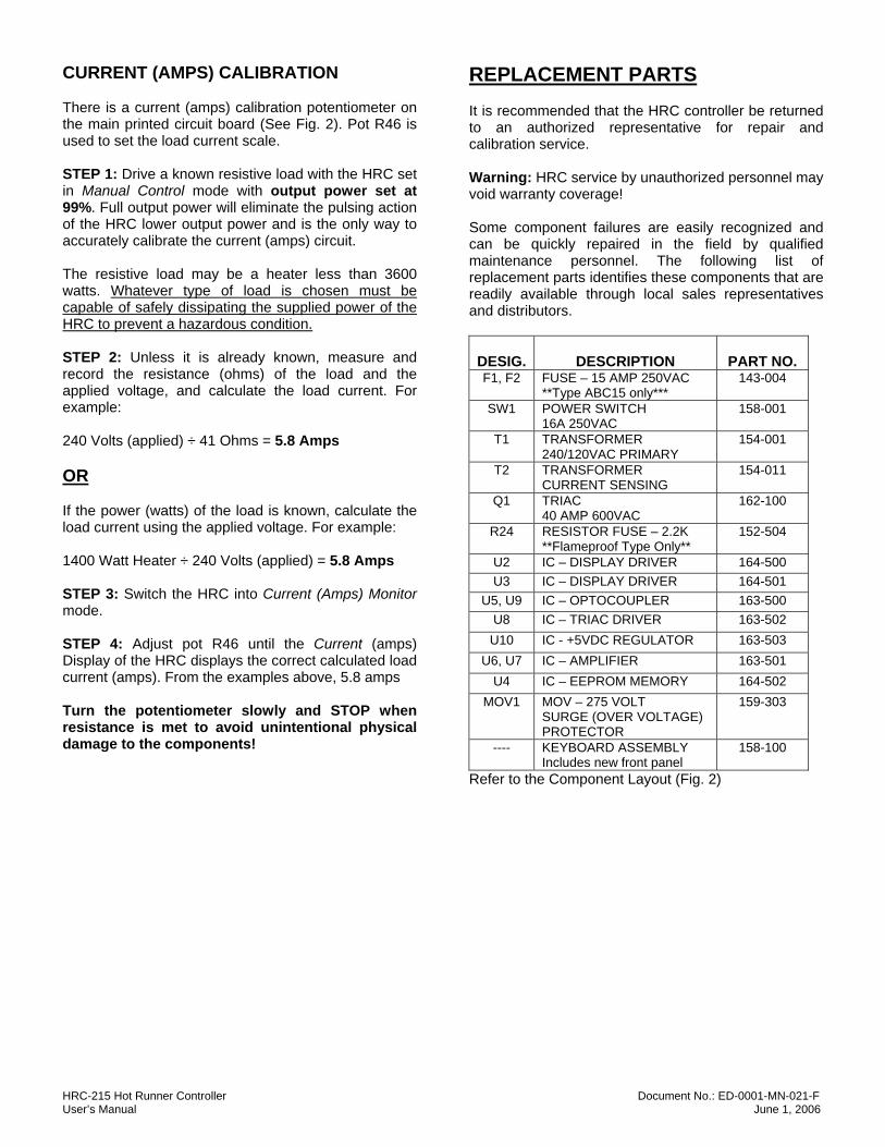
CURRENT (AMPS) CALIBRATION There is a current (amps) calibration potentiometer on the main printed circuit board (See Fig. 2). Pot R46 is used to set the load current scale. STEP 1: Drive a known resistive load with the HRC set in Manual Control mode with output power set at 99%. Full output power will eliminate the pulsing action of the HRC lower output power and is the only way to accurately calibrate the current (amps) circuit. The resistive load may be a heater less than 3600 watts. Whatever type of load is chosen must be capable of safely dissipating the supplied power of the HRC to prevent a hazardous condition. STEP 2: Unless it is already known, measure and record the resistance (ohms) of the load and the applied voltage, and calculate the load current. For example: 240 Volts (applied) ÷ 41 Ohms = 5.8 Amps OR If the power (watts) of the load is known, calculate the load current using the applied voltage. For example: 1400 Watt Heater ÷ 240 Volts (applied) = 5.8 Amps STEP 3: Switch the HRC into Current (Amps) Monitor mode. STEP 4: Adjust pot R46 until the Current (amps) Display of the HRC displays the correct calculated load current (amps). From the examples above, 5.8 amps Turn the potentiometer slowly and STOP when resistance is met to avoid unintentional physical damage to the components!
REPLACEMENT PARTS It is recommended that the HRC controller be returned to an authorized representative for repair and calibration service. Warning: HRC service by unauthorized personnel may void warranty coverage! Some component failures are easily recognized and can be quickly repaired in the field by qualified maintenance personnel. The following list of replacement parts identifies these components that are readily available through local sales representatives and distributors.
DESIG.
DESCRIPTION
PART NO.
F1, F2 FUSE – 15 AMP 250VAC **Type ABC15 only***
143-004
SW1 POWER SWITCH 16A 250VAC
158-001
T1 TRANSFORMER 240/120VAC PRIMARY
154-001
T2 TRANSFORMER CURRENT SENSING
154-011
Q1 TRIAC 40 AMP 600VAC
162-100
R24 RESISTOR FUSE – 2.2K **Flameproof Type Only**
152-504
U2 IC – DISPLAY DRIVER 164-500 U3 IC – DISPLAY DRIVER 164-501
U5, U9 IC – OPTOCOUPLER 163-500 U8 IC – TRIAC DRIVER 163-502 U10 IC - +5VDC REGULATOR 163-503
U6, U7 IC – AMPLIFIER 163-501 U4 IC – EEPROM MEMORY 164-502
MOV1 MOV – 275 VOLT SURGE (OVER VOLTAGE) PROTECTOR
159-303
---- KEYBOARD ASSEMBLY Includes new front panel
158-100
Refer to the Component Layout (Fig. 2)
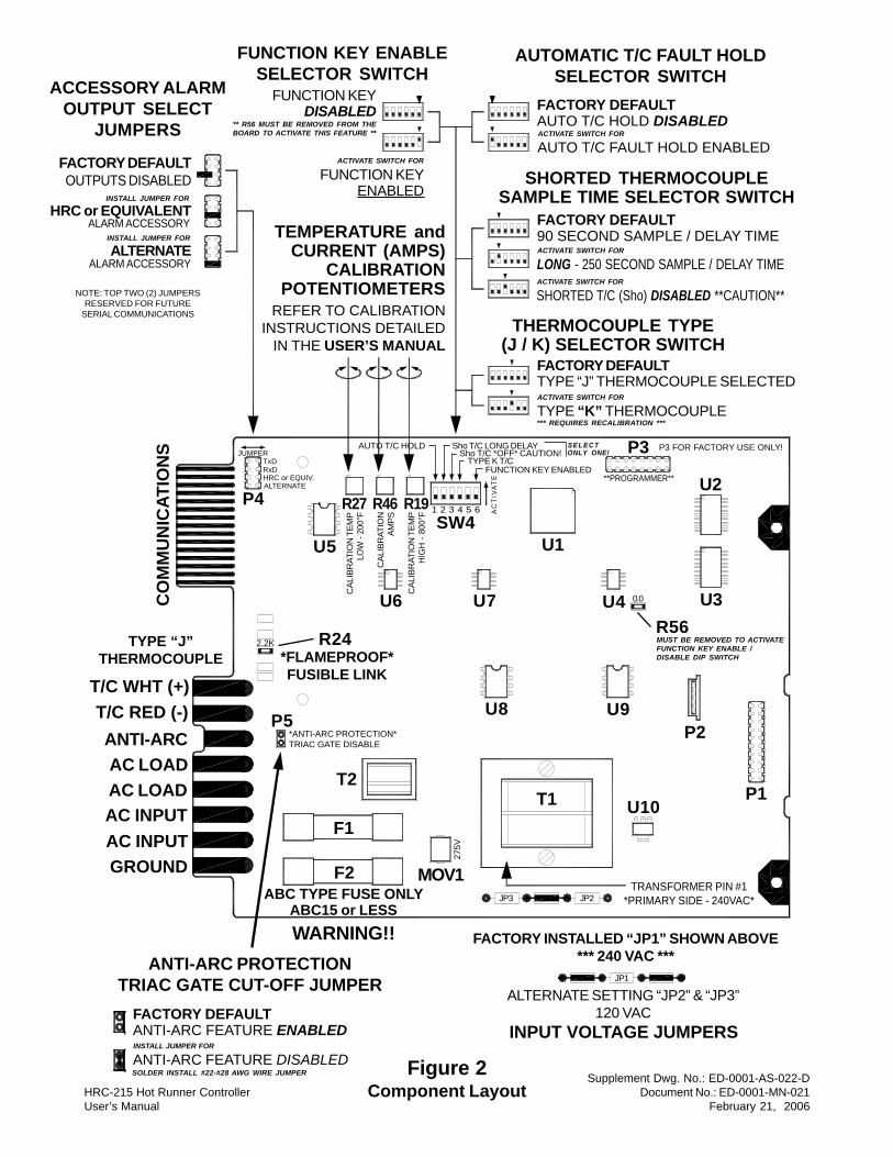
ANTI-ARC PROTECTIONTRIAC GATE CUT-OFF JUMPER
FACTORY DEFAULTANTI-ARC FEATURE ENABLED
ANTI-ARC FEATURE DISABLEDINSTALL JUMPER FOR
HRC-215 Hot Runner ControllerUser’s Manual
Supplement Dwg. No.: ED-0001-AS-022-DDocument No.: ED-0001-MN-021
February 21, 2006
Figure 2Component Layout
F1
F2
T1
INPUT VOLTAGE JUMPERS
FACTORY INSTALLED “JP1” SHOWN ABOVE*** 240 VAC ***
ALTERNATE SETTING “JP2” & “JP3”120 VAC
JP3 JP2
JP1
2.2K
TRANSFORMER PIN #1*PRIMARY SIDE - 240VAC*
U8
R24*FLAMEPROOF*FUSIBLE LINK
T/C WHT (+)T/C RED (-)ANTI-ARCAC LOADAC LOADAC INPUTAC INPUTGROUND
TYPE “J”THERMOCOUPLE
CO
MM
UN
ICAT
ION
S
R27
U5
U6
R46
U1
U7
P3
U4
P2
SW4
U10P1
P4
U3
U2
AUTO T/C HOLD
CAL
IBR
ATIO
N T
EMP
LOW
- 20
0°F
**PROGRAMMER**
P3 FOR FACTORY USE ONLY!JUMPER
TxDRxDHRC or EQUIV.ALTERNATE
ACCESSORY ALARMOUTPUT SELECT
JUMPERS
AUTOMATIC T/C FAULT HOLDSELECTOR SWITCH
NOTE: TOP TWO (2) JUMPERSRESERVED FOR FUTURE
SERIAL COMMUNICATIONS
FACTORY DEFAULTOUTPUTS DISABLED
HRC or EQUIVALENTINSTALL JUMPER FOR
ALARM ACCESSORY
ALTERNATEINSTALL JUMPER FOR
ALARM ACCESSORY
FACTORY DEFAULTAUTO T/C HOLD DISABLED
AUTO T/C FAULT HOLD ENABLEDACTIVATE SWITCH FOR
TEMPERATURE andCURRENT (AMPS)
CALIBRATIONPOTENTIOMETERS
REFER TO CALIBRATIONINSTRUCTIONS DETAILED
IN THE USER’S MANUAL
WARNING!!
ABC TYPE FUSE ONLYABC15 or LESS
SHORTED THERMOCOUPLESAMPLE TIME SELECTOR SWITCH
FACTORY DEFAULT90 SECOND SAMPLE / DELAY TIME
LONG - 250 SECOND SAMPLE / DELAY TIMEACTIVATE SWITCH FOR
SHORTED T/C (Sho) DISABLED **CAUTION**ACTIVATE SWITCH FOR
MOV1
T2
275V
P5*ANTI-ARC PROTECTION*TRIAC GATE DISABLE
AC
TIV
AT
E
Sho T/C LONG DELAYSho T/C *OFF* CAUTION!
U9
SOLDER INSTALL #22-#28 AWG WIRE JUMPER
R19
CAL
IBR
ATIO
N T
EMP
HIG
H -
800°
F
CAL
IBR
ATIO
NAM
PS
TYPE K T/CFUNCTION KEY ENABLED
S E L E C TONLY ONE!
THERMOCOUPLE TYPE(J / K) SELECTOR SWITCH
FACTORY DEFAULTTYPE “J” THERMOCOUPLE SELECTED
TYPE “K” THERMOCOUPLEACTIVATE SWITCH FOR
*** REQUIRES RECALIBRATION ***
FUNCTION KEY ENABLESELECTOR SWITCH
FUNCTION KEYDISABLED
FUNCTION KEYENABLED
ACTIVATE SWITCH FOR
1 2 3 4 5 6
** R56 MUST BE REMOVED FROM THEBOARD TO ACTIVATE THIS FEATURE **
0.0
R56MUST BE REMOVED TO ACTIVATEFUNCTION KEY ENABLE /DISABLE DIP SWITCH
HRC-215 Hot Runner Controller Document No.: ED-0001-MN-021-F User’s Manual June 1, 2006
DISCLAIMER The information contained in this manual is proprietary and supplied for customer use only. Any unauthorized reproduction of this document is strictly prohibited. All information contained in this document is deemed accurate at the time of its publication. Every effort will be made to insure that its contents match the hardware supplied. Specifications, hardware and software are subject to change without notice and the manufacturer assumes no obligation of informing the holder of this document of such changes. †D-M-E®, G-Series® and Smart Series® are all registered trademarks of D-M-E Company. ‡Athena is a registered trademark of Athena Controls, Incorporated.
LIMITED WARRANTY The manufacturer warrants that this product will be free from defects in materials and workmanship for a period of one year from the date of shipment. The manufacturer, at its discretion, may or may not grant warranty service if it is determined that this product has been abused, used in a system or application which it was not designed for, altered or tampered with by unauthorized personnel. If warranty service is applicable the manufacturer, at its option, may either repair the damaged product without charge for parts and labor or provide a replacement product in exchange for the defective unit. This warranty excludes fuses. Appropriate arrangements must be made with a sales agent prior to the return of any material.