uic systems engineering report-signed
TRANSCRIPT
Systems EngineeringReport
NASA Robotic Mining Competition
Engineering Design TeamUniversity of Illinois at Chicago
Compiled by:Michael Bailey
Edgar CollinKrystian Gebis
Tim Mueller-SimAmmar SubeiBasheer Subei
Faculty AdvisorMilos Zefran
Team Members: Michael Bailey, Krystian Gebis, Jon Kopfer, Mateusz Kubak, Tim Mueller-Sim, Nasif Mahmood, Colin Sheppard, Ismail Siddiqui, Ammar Subei, Basheer Subei and Gerard Ziomek
The Faculty adviser has reviewed this document prior to its submission.
________________________________________
Contents
1 Introduction 1
2 Pre-Phase A and Phase A 12.1 Mission Objective and Design Philosophy . . . . . . . . . . . . . . . . . . . . . . . . . . . . . 12.2 Stakeholder Expectations . . . . . . . . . . . . . . . . . . . . . . . . . . . . . . . . . . . . . . 12.3 2014 Failure Mode Analysis and 2015 Robot Objectives . . . . . . . . . . . . . . . . . . . . . 22.4 System Requirements . . . . . . . . . . . . . . . . . . . . . . . . . . . . . . . . . . . . . . . . 22.5 System Overview . . . . . . . . . . . . . . . . . . . . . . . . . . . . . . . . . . . . . . . . . . . 22.6 Concept of Operations . . . . . . . . . . . . . . . . . . . . . . . . . . . . . . . . . . . . . . . . 32.7 Work Breakdown Structure . . . . . . . . . . . . . . . . . . . . . . . . . . . . . . . . . . . . . 42.8 Project Simulation Models . . . . . . . . . . . . . . . . . . . . . . . . . . . . . . . . . . . . . . 4
3 Phase B: Preliminary Design 43.1 Interface Assembly (Base Chassis) . . . . . . . . . . . . . . . . . . . . . . . . . . . . . . . . . 43.2 Preliminary Design Reviews of Interface Assembly . . . . . . . . . . . . . . . . . . . . . . . . 53.3 Locomotion Configuration . . . . . . . . . . . . . . . . . . . . . . . . . . . . . . . . . . . . . . 53.4 Simulation Model of Locomotion . . . . . . . . . . . . . . . . . . . . . . . . . . . . . . . . . . 63.5 Preliminary Reviews of Simulation Model of Robot for Autonomy . . . . . . . . . . . . . . . 73.6 Wheel Assembly . . . . . . . . . . . . . . . . . . . . . . . . . . . . . . . . . . . . . . . . . . . 73.7 Preliminary Design Review of Wheel Assembly . . . . . . . . . . . . . . . . . . . . . . . . . . 83.8 Upper Assembly . . . . . . . . . . . . . . . . . . . . . . . . . . . . . . . . . . . . . . . . . . . 83.9 Review of Joint Reliability . . . . . . . . . . . . . . . . . . . . . . . . . . . . . . . . . . . . . . 83.10 Control System . . . . . . . . . . . . . . . . . . . . . . . . . . . . . . . . . . . . . . . . . . . . 83.11 Preliminary Reviews of Control System . . . . . . . . . . . . . . . . . . . . . . . . . . . . . . 93.12 Power System . . . . . . . . . . . . . . . . . . . . . . . . . . . . . . . . . . . . . . . . . . . . . 93.13 Communication System . . . . . . . . . . . . . . . . . . . . . . . . . . . . . . . . . . . . . . . 103.14 Preliminary Review of Communication System . . . . . . . . . . . . . . . . . . . . . . . . . . 103.15 Autonomy . . . . . . . . . . . . . . . . . . . . . . . . . . . . . . . . . . . . . . . . . . . . . . . 11
3.15.1 Sensor Data . . . . . . . . . . . . . . . . . . . . . . . . . . . . . . . . . . . . . . . . . . 113.15.2 Localization . . . . . . . . . . . . . . . . . . . . . . . . . . . . . . . . . . . . . . . . . . 113.15.3 Odometry Concept Design Review . . . . . . . . . . . . . . . . . . . . . . . . . . . . . 123.15.4 3D Depth data of Immediate Surroundings . . . . . . . . . . . . . . . . . . . . . . . . 123.15.5 Path Planning: Motion Trajectories . . . . . . . . . . . . . . . . . . . . . . . . . . . . 12
3.16 Interface Management . . . . . . . . . . . . . . . . . . . . . . . . . . . . . . . . . . . . . . . . 133.17 Technical Resource Management . . . . . . . . . . . . . . . . . . . . . . . . . . . . . . . . . . 143.18 Risk Management . . . . . . . . . . . . . . . . . . . . . . . . . . . . . . . . . . . . . . . . . . 15
4 Phase C: Final Design and Fabrication 164.1 Established Fabrication Procedure . . . . . . . . . . . . . . . . . . . . . . . . . . . . . . . . . 164.2 Software . . . . . . . . . . . . . . . . . . . . . . . . . . . . . . . . . . . . . . . . . . . . . . . . 17
4.2.1 Integration . . . . . . . . . . . . . . . . . . . . . . . . . . . . . . . . . . . . . . . . . . 174.2.2 State Machine . . . . . . . . . . . . . . . . . . . . . . . . . . . . . . . . . . . . . . . . 17
4.3 Final Design Review . . . . . . . . . . . . . . . . . . . . . . . . . . . . . . . . . . . . . . . . . 19
5 Phase D: System Assembly, Integration, Test and Launch 195.1 Assembly Review of Bolted Connections . . . . . . . . . . . . . . . . . . . . . . . . . . . . . . 195.2 Testing and Verification . . . . . . . . . . . . . . . . . . . . . . . . . . . . . . . . . . . . . . . 19

6 Project Management 206.1 Schedule . . . . . . . . . . . . . . . . . . . . . . . . . . . . . . . . . . . . . . . . . . . . . . . . 206.2 Peer Review Structure . . . . . . . . . . . . . . . . . . . . . . . . . . . . . . . . . . . . . . . . 206.3 Financial Assessment . . . . . . . . . . . . . . . . . . . . . . . . . . . . . . . . . . . . . . . . . 20
A System Overview 21
B Program Gantt Chart 22

1 Introduction
The NASA Robotic Mining Competition is an event that challenges university students to design and builda mining robot capable of operating under simulated planetary conditions, such as those that would beencountered on the surface of the Moon or Mars. The requirements of the competition also provide universitystudents with the opportunity to engage younger students in the fields of science, technology, engineering,and mathematics. Throughout the mining portion of the competition, points are awarded for optimizingparameters such as vehicle mass, overall size, regolith simulant tolerance and projection, and autonomousoperation.
A systems engineering approach is necessary to ensure optimal design, operation, and reliability of thefinal mining robot prototype. In essence, it minimizes risk over the lifecycle of the entire project, and ensuresthat all likely aspects of the project are considered and integrated into the whole. Fantastic examples ofthe robustness of a project developed using systems engineering principles are the NASA rovers Sojourner,Opportunity, Spirit, and Curiosity. The engineers and scientists who developed these robots undertook theultimate test; sending their design on a 140,000,000 mile, two and a half billion dollar journey with no chanceto repair an oversight or fix an afterthought. Their success required a strict systems engineering approach,which in turn began with accurate system models.
This paper aims to describe the following system engineering processes that the UIC team used to developthe Surus autonomous mining robot. A well-tested and successful approach is as follows: comprehensivelyidentify project goals, develop a concept of operations that describes the mining robot’s needs within itsoperating environment, develop testable system requirements, document the detailed design of subsystems,implement the finalized designs, and verify and validate system operations. As discussed in the NASASystems Engineering Handbook, systems engineering looks at the “big picture” when technical decisions haveto be made, and ensures the final design is safe and balanced in the face of conflicting constraints [1].
2 Pre-Phase A and Phase A
2.1 Mission Objective and Design Philosophy
The primary objective of the Surus is the collection and deposition of lunar regolith simulant within theframework of rules and constraints set by the NASA Robotic Mining Competition. Secondary objectivesinclude the minimization of total robot mass, autonomous operation of control systems, and efficient powerusage, while lesser emphasis was placed on minimizing communications bandwidth. The team’s designphilosophy is to optimize the holistic performance of the system, instead of trying to optimize a specifictechnical resource alone. Optimization of these parameters will increase the team’s chances of winning theprestigious Joe Kosmo Award for Excellence.
2.2 Stakeholder Expectations
The following stakeholders were defined: the University of Illinois at Chicago is a stakeholder because itprovides the primary source of financial budget and facilities. The University’s intended use of the project isto create technology development in robotic design and provide students with additional avenues for learningand development. NASA was defined as a stakeholder for creating and hosting the competition. NASA’sintended use of the project is to develop technology on planetary excavation [2] The team’s faculty advisor isa stakeholder providing an investment of time to ensure the technical merit of the project. Faculty advisorintended use is to create technology development in mobile robot configurations and provide students withadditional avenues for learning and technical development. Each of these stakeholders expects a planetaryexcavator as a product.
1

2.3 2014 Failure Mode Analysis and 2015 Robot Objectives
Analysis of the previous project was conducted as part of phase F (project closeout) for the 2014 project.A review of phase F findings was conducted by all the team members upon return from the competition inJune of 2014. The output from this review was the creation of two documents 2014 Failure Mode Analysisand 2015 Robot Objectives. These documents (Figure 1) were constructed to identify source and causationof failures and high level objectives for the 2015 project lifecycle to help guide the next project lifecycle.
Figure 1: 2014 model Hushpuppy, 2014 Failure Mode Analysis and 2015 High-level Objectives
2.4 System Requirements
Baseline system requirements were derived from the NASA Robotics Mining Competition Rulebook [2].These were documented to ensure the system met the technical requirements of the project. Requirementswere categorized into three sections: mechanical, electrical, and software.
Figure 2: System requirements
2.5 System Overview
Figure 3: System Hierarchy
2

2.6 Concept of Operations
Two preliminary concepts of operations (conops) were developed for Surus. The overall conops were devel-oped corresponding to competition rules and the intended scope of operation (Figure 4). This concept modelsimulates requirements of the overall system operations.
Figure 4: Overall system conops
1. Place the robot into the mining arena
2. Initialize the robot’s power systems for initial systembootup sequence to establish network connection
3. Initialize internal autonomous system data logging
4. Autonomously localize the robot’s random startingposition by locating beacon
5. Traverse through the mining arena to digging zone
6. Mine a sufficient amount of BP-1 regolith
7. Return to starting area and dump the accumulatedBP-1 regolith
8. Repeat steps 1–7 until the round time limit has beenreached
9. Constantly determine state of autonomy
10. In the event that autonomy is determined to beno longer functional, switch over to manual tele-operational mode
11. Continuously repeat steps 4–7 until round time limithas been reached
12. Once the round time limit has been reached, confirmthat all internal robot data logs have been properlysaved
13. Properly shut down the autonomy computers
14. Disengage all power systems and remove robot frommining arena
3

2.7 Work Breakdown Structure
Figure 5 presents the work breakdown structure used to guide project technical planning and scheduling.This structure was used to define the scope of work needed to complete the project, providing an outline forthe entire project.
Figure 5: Work Breakdown Structure for planetary excavator
2.8 Project Simulation Models
To evaluate structural frameworks, FEM models will be created for simulation. These framework simula-tions will consist of Euler Bernoulli beam elements for structural tubing, and plate elements for paneling.Applied loads are derived from free body diagrams and model formulations will be reviewed via peer review.More complex component geometries will be modeled using finite element simulation from a validated CADsoftware package.
The models used to evaluate motor control systems will be done in MATLAB or Simulink. These modelswill be used to create the preliminary design of the control system. In this formulation process, dynamics andcontrol parameters can be simulated and tuned. A holistic simulation of the robot can be done in Gazebo,which can be used in conjunction with the Robot Operating System (ROS ).
The basis for the mechanism used to deposit regolith in the collector bin will be a revolute-planar-revolutefour bar linkage mechanism, which can be analyzed using vector loop closure. Gazebo, the primary simulatorused in conjunction with ROS, is only capable of simulating lower pairs. Mechanisms which feature higherorder pairs which need to be encapsulated in this simulation will be highly penalized in design revisions.
3 Phase B: Preliminary Design
3.1 Interface Assembly (Base Chassis)
The design goal for this sub-assembly was to create a modular design where the interface assembly wasable to provide a central chassis, which is the primary high level interface for the subsystems of the robot.Additionally, the assembly must ensure structural stability, have a geometry that facilitates the miningobjective of the competition, and provide protection from the harmful regolith for delicate electrical andcomputer subsystems on the robot (Figure 6) displays the subsystems which connect to the interface assembly.
4

Figure 6: Subsystems which connect to the interface assembly.
With the specified design constraints, the general geometry of the interface assembly was defined. Inorder to facilitate optimal decisions in preliminary design, the doctrine of successive refinement was employedto create crisp assessments of system functionality [1]. From this geometry initial concept drafts were createdand iterated with the goal of minimizing mass while maintaining structural integrity of the framework. Inorder to create a finite element model for the framework, the nodes, locations, element types, and materialproperties were defined. The finite element model was constructed using Euler Bernoulli Beam elementsfor the structural tubing and plate elements for the panels and base plane. The purpose of this refinementwas to ensure the design met system requirements and to validate that the subsystem fulfilled structuralrequirements.
3.2 Preliminary Design Reviews of Interface Assembly
Throughout the design process, technical reviews of the design were performed. The machinists at the UICPhysics Machine Shop were a receptive and instrumental audience for the project. The primary focuses ofthe reviews between the machine shop and the team were manufacturing techniques and ensuring robustnessof the design. A few notable outcomes of these reviews were the use of plugs in structural tubing, in areaswhere wear on the tube could reduce component life, and insights into metal bending. A preliminary reviewwas requested with the student organization governing body on the design of the interface assembly.
3.3 Locomotion Configuration
The locomotion configuration must fulfill the requirements of navigating and performing tasks in an unstruc-tured environment [3]. The team’s previous model utilized a non-articulated tied mode for the locomotionconfiguration. The locomotion system determines the performance of a mobile robot. A high performancelocomotion system will allow a robot to maintain control authority on hazardous terrain. Loss of mobilityis a common failure in the NASA Robotic Mining Competition, so much so that the judges have coineda term “diagonalization”. Diagonalization describes a failure which occurs when one wheel loses tractioncausing another wheel to dig itself into a hole, resulting in a catastrophic loss of mobility. The team wasinterested in adopting concepts presented in planetary exploration locomotion studies with the aim of in-creasing the range of operating conditions of the planetary excavator. In order to determine what locomotionconfiguration would be appropriate for the robot, the team developed a trade study (Figure 7).
5

Figure 7: Locomotion configuration decision matrix.
1. Reliability: Evaluated based on technology devel-opment and published evaluations of configurations,possible failure modes including ability to effectivelymanufacture and assemble the system.
2. Ruggedness: Evaluated based on number of ex-posed kinematic joints, and resilience to harsh envi-ronments.
3. Simplicity: Evaluated based on number and typeof kinematic pairs and links,as well as manufactura-bility.
4. Mass: Evaluated by number of links, and powertransmission components.
5. Performance: Evaluated by documented perfor-mance of systems from technology development andpublished evaluations of configurations.
6. Geometry: Evaluated by analyzing required spaceallocation for each configuration.
7. Development: Evaluated based on the quantity ofconfiguration documentation and the mobile robotcommunity’s response to work.
Figure 8: Design goals for locomo-tion system
The MSD (mass spring damper) system was found to have poorgeometry, mass and to be harmful to locomotion performance in thisterrain [4]. The Crab I, II, MER and RCL-E configurations exhibitstrong locomotion characteristics [5, 6, 7]. The MER configuration waspenalized for its use of a differential gear and a higher order pair (seeSection 2.8 ). The tied system scored well overall, but scored poorly inmass due to having additional power transmission components. TheCrab configurations scored lower than overall RCL-E due to additionallinks and kinematic pairs (mass and points of failure). Based on thedesign goals for this subsystem (Figure 8) an RCL-E analogous systemwas selected.
From this trade study, the basis of the locomotion systemwas defined. The kinematics of this system are the link ra-
tios and joint types employed in RCL-E. In order to facilitate good decisions in preliminary de-sign, the doctrine of successive refinement was employed to create crisp assessment systems (Figure9). From these iterations, the team defined the structural geometry of the links, defined neededinterfaces, and simplified the system removing walking actuators and explicit steering functionality.
3.4 Simulation Model of LocomotionBase Link
Transverse Bogie
Right Rear Wheel
Le4 Rear Wheel
Base Link
Bo5om Link
Front Ver9cal Link
Middle Ver9cal Link
Middle Wheel
Front Wheel
Top Link
Failure Mode Analysis
Findings from Pre-‐Phase A and Phase A
Pic 1
Figure 9: Diagram of successive refinementfor locomotion system
The team classified the simulation model for the robot to bea tangible subsystem, because it forms the primary basis forintegration/testing and design evaluations. In the ROS archi-tecture, this model is treated as a node allowing for the auton-omy architecture to be simulated in parallel with the robot’sphysical response. This model creates a platform for testingdifferent locomotion configurations utilizing the Gazebo physicsengine. The important identified parameters to include in thesimulation were terrain geometry, robot kinematics, and robotphysical properties.
6
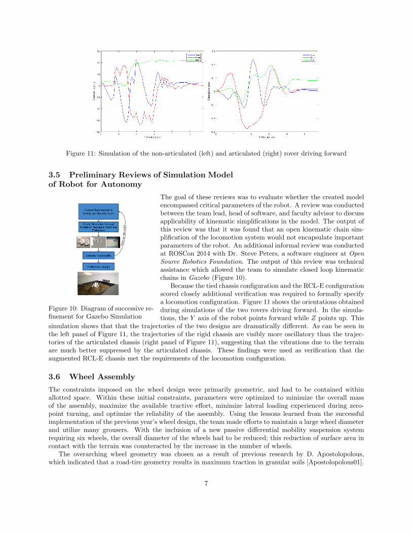
Figure 11: Simulation of the non-articulated (left) and articulated (right) rover driving forward
3.5 Preliminary Reviews of Simulation Modelof Robot for Autonomy
Figure 10: Diagram of successive re-finement for Gazebo Simulation
The goal of these reviews was to evaluate whether the created modelencompassed critical parameters of the robot. A review was conductedbetween the team lead, head of software, and faculty advisor to discussapplicability of kinematic simplifications in the model. The output ofthis review was that it was found that an open kinematic chain sim-plification of the locomotion system would not encapsulate importantparameters of the robot. An additional informal review was conductedat ROSCon 2014 with Dr. Steve Peters, a software engineer at OpenSource Robotics Foundation. The output of this review was technicalassistance which allowed the team to simulate closed loop kinematicchains in Gazebo (Figure 10).
Because the tied chassis configuration and the RCL-E configurationscored closely additional verification was required to formally specifya locomotion configuration. Figure 11 shows the orientations obtainedduring simulations of the two rovers driving forward. In the simula-tions, the Y axis of the robot points forward while Z points up. This
simulation shows that that the trajectories of the two designs are dramatically different. As can be seen inthe left panel of Figure 11, the trajectories of the rigid chassis are visibly more oscillatory than the trajec-tories of the articulated chassis (right panel of Figure 11), suggesting that the vibrations due to the terrainare much better suppressed by the articulated chassis. These findings were used as verification that theaugmented RCL-E chassis met the requirements of the locomotion configuration.
3.6 Wheel Assembly
The constraints imposed on the wheel design were primarily geometric, and had to be contained withinallotted space. Within these initial constraints, parameters were optimized to minimize the overall massof the assembly, maximize the available tractive effort, minimize lateral loading experienced during zero-point turning, and optimize the reliability of the assembly. Using the lessons learned from the successfulimplementation of the previous year’s wheel design, the team made efforts to maintain a large wheel diameterand utilize many grousers. With the inclusion of a new passive differential mobility suspension systemrequiring six wheels, the overall diameter of the wheels had to be reduced; this reduction of surface area incontact with the terrain was counteracted by the increase in the number of wheels.
The overarching wheel geometry was chosen as a result of previous research by D. Apostolopolous,which indicated that a road-tire geometry results in maximum traction in granular soils [Apostolopolous01].
7

Working within geometric constraints, a rudimentary design was developed that consisted of 3 structuralcomponents: an outer hub which mates to the drive-train, transverse beams upon which the shell of thewheel is placed, and the inner hub which rigidly connects the transverse beams together. These primarycomponents would be iteratively altered until all desired parameters are optimized.
3.7 Preliminary Design Review of Wheel Assembly
Figure 12: Wheel hub tradestudy
Throughout the design process, technical reviews of the wheel design wereperformed. A primary objective of the initial technical reviews was to in-vestigate the feasibility of incorporating compliance into the hub of thewheel, so as to decrease shock loading on the rest of the robot frameresulting from the wheel’s interaction with the terrain. After perform-ing extensive finite element analysis and a trade study shown in Figure12, it was determined that a rigid spoke design would be optimal, asthe increased performance of the compliant hub would not overcome theincreased cost and manufacturability.
3.8 Upper Assembly
The role of the upper assembly was to achieve the mining objectives of the system. For this functionalitythe upper assembly must collect, store, and deposited regolith. The design goal was to design an excavationsystem specifically tailored for a Martian environment. In a low gravity environment normal force createdfrom weight will be lower additionally with low robot mass (mass is a valuable technical resource). To accountfor this the excavation system should use work, rather than pure force to excavate. Satisfy this constraintthe robot’s dig mechanism should collect regolith using continuous excavation. Bucket ladders and bucketwheels are two continuous excavators. Bucket wheels have been shown to be more robust than bucket laddershowever, to minimize mass the team accepted this trade off and selected a bucket ladder as the excavationmethod. The other tradeoff that had to be analyzed in design of upper assembly was use of one or two linearactuators to raise and lower the upper assembly. Two linear actuators would require a well-tuned feedbackcontrol system, but could reduce the mass of framework by creating for efficient structural geometry. Onelinear actuator would require a simple control system but require greater force to raise the system, effectdepositing regolith, and create a cantilever beam structure. With the ability to tune control specificationsthe additional control complexity of a two linear actuator set up was deemed acceptable. With mass as atechnical resource carbon fiber composite offered a mass efficient method of designing a container basin.
3.9 Review of Joint Reliability
The goal of this review was to ensure that joints used in the robot, both permanent and non-permanent, weredesigned reliably and met technical requirements of connection types. In this review, joints were categorizedby joint types. Welds were identified as the primary permanent joint used in the system. To ensure reliability,freebody diagrams and models were reviewed such that the joint strength was sufficient for the expectedloading condition. Non-permanent joints were designed and reviewed in accordance to bolted connectionstandards. Bolted connections were evaluated by modeling equivalent created spring and safety guidelines.Figure 13 displays the configuration management of non-permanent connection designs in Phase B. Thisreview impacted the successive refinement across multiple subsystems of the robot.
3.10 Control System
The design goal of the robot’s control system was to optimize simplicity by evaluating control system per-formance specifications (stability, response quality and robustness) [8]. To accomplish the functionality ofsystem requirements, six actuation units were defined. Control structures and alternatives were proposed
8
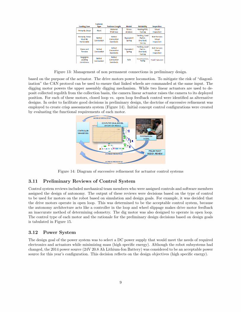
Figure 13: Management of non permanent connections in preliminary design.
based on the purpose of the actuator. The drive motors power locomotion. To mitigate the risk of “diagonl-ization” the CAN protocol can be used to ensure that linked wheels are commanded at the same input. Thedigging motor powers the upper assembly digging mechanism. While two linear actuators are used to de-posit collected regolith from the collection basin, the camera linear actuator raises the camera to its deployedposition. For each of these motors, closed loop vs. open loop feedback control were identified as alternativedesigns. In order to facilitate good decisions in preliminary design, the doctrine of successive refinement wasemployed to create crisp assessments system (Figure 14). Initial concept control configurations were createdby evaluating the functional requirements of each motor.
Figure 14: Diagram of successive refinement for actuator control systems
3.11 Preliminary Reviews of Control System
Control system reviews included mechanical team members who were assigned controls and software membersassigned the design of autonomy. The output of these reviews were decisions based on the type of controlto be used for motors on the robot based on simulation and design goals. For example, it was decided thatthe drive motors operate in open loop. This was determined to be the acceptable control system, becausethe autonomy architecture acts like a controller in the loop and wheel slippage makes drive motor feedbackan inaccurate method of determining odometry. The dig motor was also designed to operate in open loop.The control type of each motor and the rationale for the preliminary design decisions based on design goalsis tabulated in Figure 15.
3.12 Power System
The design goal of the power system was to select a DC power supply that would meet the needs of requiredelectronics and actuators while minimizing mass (high specific energy). Although the robot subsystems hadchanged, the 2014 power source (24V 20.8 Ah Lithium-Ion Battery) was considered to be an acceptable powersource for this year’s configuration. This decision reflects on the design objectives (high specific energy).
9

Figure 15: Preliminary design of control systems
3.13 Communication System
Determining what constraints the robot’s system presented, the RS-232 protocol was determined as thenecessary means of communication to the Locomotion subsystem. The Locomotion subsystem is comprisedof five individual motor controllers, which allow different subsystems to interface with the driving and diggingmotors.
To safely and automatically switch between different robot operating modes when necessary, a signalmultiplexer (SigMux) design was identified as a subsystem that would meet these needs. The SigMux fulfillsthe need to detect failures or miscommunication in the robot’s autonomy system, automatically switchingto a secondary communication pipeline, allowing for manual teleoperation to take place from the commandcenter.
The SigMux has different operating modes to ensure safety and full control over the robot. The operatingmodes are safe mode, manual mode, and autonomous mode. Safe mode, enabled by default on systempower-up, disconnects the robot’s communication with the motor controllers for safety precautions, when itis desired to either halt the robot or switch from autonomous mode to manual mode (vice versa); safety modewill also be manually enabled from the command center at the end of each competition round. Autonomousmode enables the possibility for the robot’s on board autonomy computers to communicate with the motorcontrollers over the RS-232 protocol. Manual mode enables for teleoperation commands being sent overa secondary WiFi module on-board SigMux itself. The SigMux then allows for only the command centerteleoperation commands to be sent to the motor controllers, disregarding any motor commands coming fromthe autonomy subsystem.
The robot’s different modes can be chosen from a higher level user interface that is controlled from thecommand center.
As a failsafe system, the SigMux has also been designed to contain a watchdog system, which monitorswhether a connection between the SigMux’s WiFi module and the wireless router is established. In the eventthat no connection is present for a certain amount of time, the SigMux then quickly power-cycles to try andrestart the connection to the router. This however, does not affect the state of the on board multiplexer, asit is designed to by default to allow the autonomy system to communicate with the Locomotion subsystem.The flow diagram for the communication system is shown in Figure 16.
3.14 Preliminary Review of Communication System
The Signal Multiplexer PCB design was sent to Chicago EDT’s email “list-serv”, which had multiple alumnisubscribed, for review purposes. The first revision made multiple changes that include spacing out the tracesand via holes, repositioning multiple connectors and ICs, and realigning some components for optimization.The second revision added a ground plane on the bottom layer of the SigMux circuit board, which sub-stantially decreased the amount of traces on the board and made more room for connector and via holeclearances. The second revision also eliminated the use of two unnecessary logic level shifters, thus creating
10

Figure 16: Communication flow diagram
more room and decreasing the board size. The final revision introduced the use of test points for easier in-spection of critical nodes, a new, smaller, and more efficient DC/DC converter, and furthermore decreasingthe dimensions of the board.
3.15 Autonomy
3.15.1 Sensor Data
On an extra-terrestrial mining rover, the single-most essential task for autonomy is to be able to accuratelyand reliably locate itself and its surroundings in order to navigate through unknown environments. Givenfiltered odometry data, the robot can localize itself relative to the mapped environment. Acquiring andfusing data from the environment around the robot is integral for the purposes of building this map andlocalizing itself within it. Without it, the robot will be unable to plan its actions, as it lacks sufficientinformation of its surroundings. The team has determined that the system requirements for sensor data are:
• Localization
• 3D depth data of immediate surroundings
3.15.2 Localization
There are various ways and sensor modalities that can be used to determine the odometry and location of therobot, ranging from simple methods like single-dimensional laser range-finders to 3D LIDAR scanners. Thedesign goal of localization was to optimize data usage and create an accurate odometry estimate. The teamapproached this problem by identifying the crucial pieces of data required to achieve the goal of localizationcalculation. In order to create a robust system, the team decided to collect multiple sources of localizationand integrate them into a single filtered odometry output. This data will then be used to interface with theautonomy system, specifically with the path planning and navigational subsystems. The team identified thefollowing various feasible methods to obtain localization data:
11

• Wheel Encoders
• RGB-Depth sensors (Kinect)
• 2D LIDAR
• 3D LIDAR
• Inertial Measurement Unit (IMU)
• RF Beacon
• Stereoscopic Camera Visual Odometry
• Visual Marker Beacon
• Optical-Laser Beacon
3.15.3 Odometry Concept Design Review
In a chaotic particulate terrain environment, wheel slippage makes wheel encoder data unreliable as anodometry input. The 3D LIDAR sensors were prohibitively expensive and would produce too much datawhere more then half of it would not be used. The team determined that a 2D LIDAR would not be usedsince the competition requirements specify that a robot cannot use the arena walls for means of localiza-tion. This eliminates discrepancy as to whether or not the team is meeting the competition requirements.The stereoscopic visual odometry algorithms required excessive amounts of processing power to achieve realtime operation. Finally, RF and Optical-Laser beacon methods were ruled out as the team lacked sufficientexperience in implementing these methods.
After a review of the available methods of odometry, the team decided that the primary odometrysource will be obtained using visual markers placed above the dumping bin, which act as a beacon, yieldingrelative position and orientation to the bin (represented as a transform from the camera frame to the markerframe). The team determined that the secondary odometry sources would be an IMU as well as a 3D visualodometry algorithm using data from the Kinect RGB-D sensor, disregarding all 3D data points above thehighest possible terrain threshold set by the competition rules (30cm) to avoid discrepancy of using the arenawalls for means of localization.
3.15.4 3D Depth data of Immediate Surroundings
Besides odometry, a secondary purpose of the sensor data that we collect from the terrain is for obstacledetection/avoidance. When a large enough obstacle (such as a rock or boulder) is found, it needs to bemarked as an obstacle and placed correctly in the map of surroundings that we build.
3.15.5 Path Planning: Motion Trajectories
The next objective for the autonomy system is to identify a heuristically optimal plan to reach the goal.This involves calculating a path to follow on the ground to and from digging/dumping sites. The teamdetermined that calculating motion trajectories across our map in three dimensions would require excessiveamounts of processing power and development time to achieve. Therefore, a more simplified approach wasdeemed necessary, specifically one that reduces the amount of unnecessary data that the robot gathers fromthe environment. An appropriate and elegant solution is to assume a two-dimensional motion trajectoryfor our navigation purposes. The three-dimensional mapped environment will simply be projected onto atwo-dimensional plane, and the obstacles can be placed on a two-dimensional occupancy grid or map, witheach cell in the map representing the cost of traversing over that region. Thus, a costmap [9] is built fromthe surroundings and is used as an input into the algorithm to plan motion trajectories.
The second type of input into the motion planning algorithm is the possible motions that the rover canperform. These are called the motion primitives, and they represent the most basic discrete motion param-eters that the rover can perform and is physically constrained by. The motion primitives we calculated areshown in Figure 17.
Once the motion planning algorithm receives these two inputs, it can determine an optimal motiontrajectory from the current map position to the goal, given the motion primitive constraints and the cost oftraversing certain areas of the map. However, there are many ways to design an algorithm that calculates
12

Figure 17: Motion Primitives
such a motion trajectory. The team identified two broad categories of these, namely those algorithms thatdetermine the most optimal trajectory after an exhaustive search, and those algorithms that heuristicallydetermine an optimal enough trajectory given an error bound. Given the processing power constraints, theteam decided to use heuristic algorithms to determine the motion trajectory.
3.16 Interface Management
Figure 18: The articulated roverwith local coordinate frames foreach link
The interface assembly frame was defined as the central reference coor-dinate frame (base frame). Figure 18 displays the coordinate systems ofthe rigid bodies of the robot. Camera feedback is collected relative to thecamera frame which is then transformed to the baseframe. The Kinectframe is transformed by a constant translational transform. The monocu-lar camera frame is transformed by a rotational (servo position feedback)and translation transform (mounting location on robot).
The upper assembly is connected to the interface assembly by a rearaxle. The actuators which raise and lower the system are connected to theupper assembly and interface assembly by respective axles. The locomo-tion system connected to the interface assembly by axle originating fromthe interface frame. Electrical components are mounted on base planeor side panels of the interface assembly, secured with fasteners. Electri-cal enclosures protect components from regolith, and are mounted on thebase plane or side panels.
13

Figure 19: Exploded view and assembly view of preliminary designFigure 19 displays an exploded assembly to visualize subsystem interfaces of the robot. Control param-
eters are initialized in Roboteq Roborun, then uploaded to motor controllers. The CAN circuit connectsmotor controllers using an embedded circuit board; the circuit will be embedded to increase reliability andorganization. Sensor feedback for autonomy is collected, transformed, and sent to the the Kalman filterwhich weighs and combines sensor data. This filtered data is then used in autonomy algorithms.
3.17 Technical Resource Management
Figure 20: Phase B estimated mass budget breakdown
In Phase A, initial high-level technical resource estimates were created. Upon the completion of pre-liminary designs, technical resources were reevaluated. Two technical resources were identified as primarylimiting factors for the mission: power consumption and mass of the robot. Figure 20 displays mass break-down, showing subassembly usage of mass budget. The upper chart displays usage relative to the competitionlimit, while the lower chart displays subassembly usage relative to the team’s mass objective.
14

Energy was another critical technical resource for the mission, and our estimated energy budget break-down is shown in Figure 21.
Figure 21: Phase B estimated energy budget breakdown
Other identified technical resources were bandwidth and processing power. Conserving bandwidth as aresource, however, had a lesser priority, while processing power held a higher priority, which was measuredby the number of effective CPU cores available on all the embedded computer systems.
With the technical resource budget reviewed based off preliminary design, this completed the technicalresource management for Phase B.
3.18 Risk Management
Planetary excavation is a high risk mission, involving such hazards which could jeopardize the effectivenessof a mission. In order to effectively reduce risks and achieve the project goal, the project utilized riskmanagement concepts. Based on experience, peer reviews, and design evaluation, the following risks wereidentified from preliminary designs [10]. These risks were identified to be tracked and evaluated throughfabrication, testing, and mission deployment. The risk matrix pictured in Figure 22 displays the identifiedrisks and their risk level.
Breakdown of Team Communications: This failure is of high likeliness and frequency. It wouldnot result in mission failure, but it could however result in delays in program progress. Assistance from thefaculty advisor, regular team meetings, and an emphasis on communication were steps taken as contingencyoptions/procedures to mitigate this risk.
Regolith Coating Mechanical Interfaces: This failure is of high likeliness due to the environmentconditions. It would not result in mission failure, however it may lead to reduced performance of movingparts.
Autonomy Fails to Complete Objectives: This failure is of moderate likeliness due to the intrinsicchallenges of performing an automated task in a chaotic environment. The consequences of this failure wouldbe failure to complete autonomous excavation requiring manual control of the robot. Although this failurewould not result in complete mission failure it would greatly reduce the operational capabilities of the robot.
Incomplete Models: This failure is of high likeliness due to the chaotic environment conditions. Modelsfor terramechanics and locomotion on deformable terrain are often empirical rather than deterministic [11,12, 13, 14, 3]. The simulated robot model used in autonomy simulation used an environment consisting ofrigid bodies. The robot’s performance is dependent on the degree to which assumptions made in analysisencapsulate important parameters of the real system and environment. The contingency for this risk is toconstantly reevaluated the models used and adjust them to more accurately represent the system.
15

Figure 22: Risk matrix for planetary excavator
Failure of Feedback System: This failure is of moderate likeliness due to variation in system dynamics.This failure could lead to reduction in robot functionality. To reduce this risk, an emphasis was made onrobust design of physical systems and control structures. As a contingency plan, the operator will stopautonomous operations to troubleshoot the issue with a human in the loop.
Unexpected Loading Conditions: This failure is of moderate likeliness. This risk is innate whenworking in a chaotic environment. This condition, if not properly accounted for, could lead to partial orcomplete failure of specific subsystems on the robot. The proposed contingency plan for this risk was toinclude current limiters in the control design to guard against actuator failure.
Regolith Failure: This failure is of moderate likeliness and of serious consequence. Excessive dustproduction could lead to sensor failure, regolith may embed itself in mechanical joints to the degree thatwould cause functional failure [15]. It can also be damaging to electrical components of the robot. Tomitigate this risk, mechanical designs should be robust, electronics should be appropriately sealed, andautonomy should have appropriate redundancies. As a contingency, the autonomy system makes decisionsfrom multiple feedback units to guard against one failing.
Improper Assembly of Machine: This failure is of low likeliness. The consequence of this failurecould be mission failure. By following strict assembly procedures, the probability of this failure can bereduced. If improper assembly is noticed in testing, the contingency plan is to identify origin of improperassembly, document the failure, and adjust the assembly procedure.
Unstable Autonomy System: The likeliness of this failure is low, however the consequences are grave.If the autonomy system becomes unstable, it may become a hazard to nearby observers. As a contingencyplan the robot features an emergency stop. Also, an operator may interject and begin to teleoperate therobot.
4 Phase C: Final Design and Fabrication
4.1 Established Fabrication Procedure
In order to mitigate risk and ensure component reliability, the following fabrication procedure was imple-mented. In fabrication designs analysis of tradeoffs had to be considered. Will the part be manufacturedin-house, outsourced, or utilize additional University facilities? If the component could be reliably manu-factured using common subtractive manufacturing techniques (such as milling, shearing and cutting) or lowforce metal bending, then it would be manufactured in-house. If the component could not be manufactured
16

in house but could be manufactured using local University resources (such as 3d printing, metal bending,tube bending and welding), then that would be the primary option. After both these options are exhausted,then the fabrication would be outsourced.
Figure 23: Fabrication procedural hierarchy
Figure 24: Established tolerances forstructural and mechanical components
After each part was fabricated, it was evaluated basedon component functional requirement, and dimensional accu-racy. Figure 23 shows the procedural approach for fabrica-tion of components. If tooling to fabricate a part was notavailable, but required machinery and the tool could be fab-ricated using well-documented procedure, then the appropriatetooling would be designed and fabricated. A standard for tol-erances for components was defined in order to create relia-bility, consistency, and create interfaces for the robot. Fig-ure 24
4.2 Software
4.2.1 Integration
Given the complexity of the proposed autonomy system, the software team realized that there was a needto develop each subsystem and test it independently. There was also the issue of interfacing the differentsubsystems, and ensuring that the data structures and types between them are compatible. Therefore, thedesign objectives as a whole were to minimize:
• Development time
• Intermodular dependence
• Interface and integration problems
4.2.2 State Machine
The purpose of the state machine is to determine what action the robot should perform, or what location totravel to in the mining arena (Figure 27). The actions that the robot may perform are listed as the following:
• Localizing the robot by rotating the servo camera until we lock onto the ArUco marker. This will beperformed on the start of the run as well as if the robot loses its sense of position (Figure 28).
• Manually correct position and orientation of robot in odometric coordinate frame relative to the originof the arena map coordinate frame
17
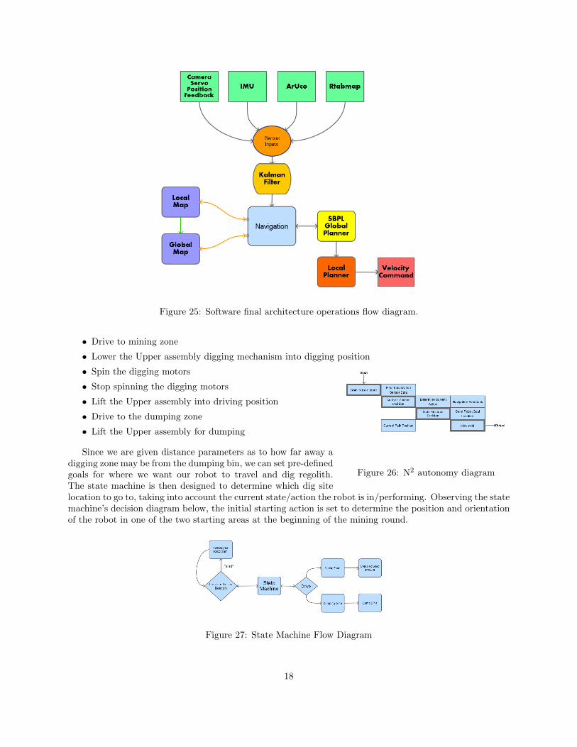
Figure 25: Software final architecture operations flow diagram.
• Drive to mining zone
• Lower the Upper assembly digging mechanism into digging position
• Spin the digging motors
• Stop spinning the digging motors
• Lift the Upper assembly into driving position
• Drive to the dumping zone
• Lift the Upper assembly for dumping
Figure 26: N2 autonomy diagram
Since we are given distance parameters as to how far away adigging zone may be from the dumping bin, we can set pre-definedgoals for where we want our robot to travel and dig regolith.The state machine is then designed to determine which dig sitelocation to go to, taking into account the current state/action the robot is in/performing. Observing the statemachine’s decision diagram below, the initial starting action is set to determine the position and orientationof the robot in one of the two starting areas at the beginning of the mining round.
Figure 27: State Machine Flow Diagram
18

Figure 28: Servosweeping-motion ofcamera
Taking into consideration the random placement and orientation of therobot, the initial localization is comprised of two simultaneous steps, whichallow us to know our current starting position relative to a beacon hang-ing above the dumping bin. The first step consists of a 180 degree servo-sweeping motion, where 0 degrees is facing directly behind the robot. This al-lows for a mounted camera to try and lock onto one of the beacon’s mark-ers (also known as ArUco generated codes), and give the robot information asto how far away from the beacon it is, as well as what orientation it is fac-ing.
In the event that the camera has locked onto one of the beacon’s markers, thestate machine will then change its state to traverse towards the mining zone. Thereis, however, an expected scenario where the sweeping motion may not allow thecamera to find the beacon; if the front of the robot is oriented towards the dumping
bin, pointing the camera directly away from the beacon, the camera’s field of view and servo’s rotation limitsbecome an evident constraint. To overcome this obstacle, the state machine is notified by the servo-sweepingprocess that the beacon could not be found and a position could not be obtained. A 180 degree zero radiusturn is then performed, to allow for the camera to observe its environment from a different viewpoint. Thisaction is then repeated, until the robot can locate the ArUco markers.
Obtaining the location of the ArUco markers, allows the state machine to continue through its actioniteration cycle; keeping track of where we are with respect to the marker then allows the robot to traverseto the mining area. Having already pre-set mining goal points with respect to the ArUco markers, the robotthen approaches first goal point and begins to dig. The state machines “dig” action consists of broadcastinga message to the actuators to lower the upper assembly digging mechanism into digging position. Once anechoing message stating that the actuators are in place is received back by the state machine, a “creep-and-dip” action is then performed by broadcasting a “spin dig motor” message to the motor controllers, andlowering a max linear and angular velocity parameter, which will then be accessed by the local path planner.
4.3 Final Design Review
The purpose of this review was to verify that fabricated components and final designs met the systemrequirements, as well as to document and compare them as built and as designed. Present at this reviewwere the core members of the mechanical, electrical, and software team.
5 Phase D: System Assembly, Integration, Test and Launch
5.1 Assembly Review of Bolted Connections
Although bolted connections are common, the typical behavior of a bolted connection is quite compli-cated [16]. Improper assembly of the machine is a risk that must be managed (Figure 22). The followingprocedure outlines the procedure for assembly of bolted connections used by the team: perform visual in-spection of clearance hole and threaded hole. Tension bolt to meet designed preload, to achieve appropriatefactors of safety by applying appropriate torque to bolt head. Visually inspect joint, such that at least twoadditional threads exist after the nut. Continue evaluation during testing phase of program.
With the created simulation model, the autonomy functionality was tested from phase B. In this sim-ulation, the motion primitives were tested and verified to be capable of functionally navigating in bothforwards and reverse. Additionally, autonomous navigation was continually tested using this simulation. Inthis on-going phase, the team aims to continue autonomy testing.
5.2 Testing and Verification
19
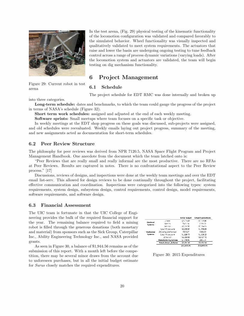
Figure 29: Current robot in testarena
In the test arena, (Fig. 29) physical testing of the kinematic functionalityof the locomotion configuration was validated and compared favorably tothe simulated behavior. Wheel functionality was visually inspected andqualitatively validated to meet system requirements. The actuators thatraise and lower the basin are undergoing ongoing testing to tune feedbackcontrol across a range of process dynamic variations (varying loads). Afterthe locomotion system and actuators are validated, the team will begintesting on dig mechanism functionality.
6 Project Management
6.1 Schedule
The project schedule for EDT RMC was done internally and broken upinto three categories.
Long-term schedule: dates and benchmarks, to which the team could gauge the progress of the projectin terms of NASA’s schedule (Figure 32).
Short term work schedules: assigned and adjusted at the end of each weekly meeting.Software sprints: Small meetups where team focuses on a specific task or objective.In weekly meetings at the EDT shop progress on these goals was discussed, sub-projects were assigned,
and old schedules were reevaluated. Weekly emails laying out project progress, summary of the meeting,and new assignments acted as documentation for short-term schedules.
6.2 Peer Review Structure
The philosophy for peer reviews was derived from NPR 7120.5, NASA Space Flight Program and ProjectManagement Handbook. One anecdote from the document which the team latched onto is:
“Peer Reviews that are really small and really informal are the most productive. There are no RFAsat Peer Reviews. Results are captured in notes. There is no confrontational aspect to the Peer Reviewprocess.” [17]
Discussions, reviews of designs, and inspections were done at the weekly team meetings and over the EDTemail list-serv. This allowed for design reviews to be done continually throughout the project, facilitatingeffective communication and coordination. Inspections were categorized into the following types: systemrequirements, system design, subsystem design, control requirements, control design, model requirements,software requirements, and software design.
6.3 Financial Assessment
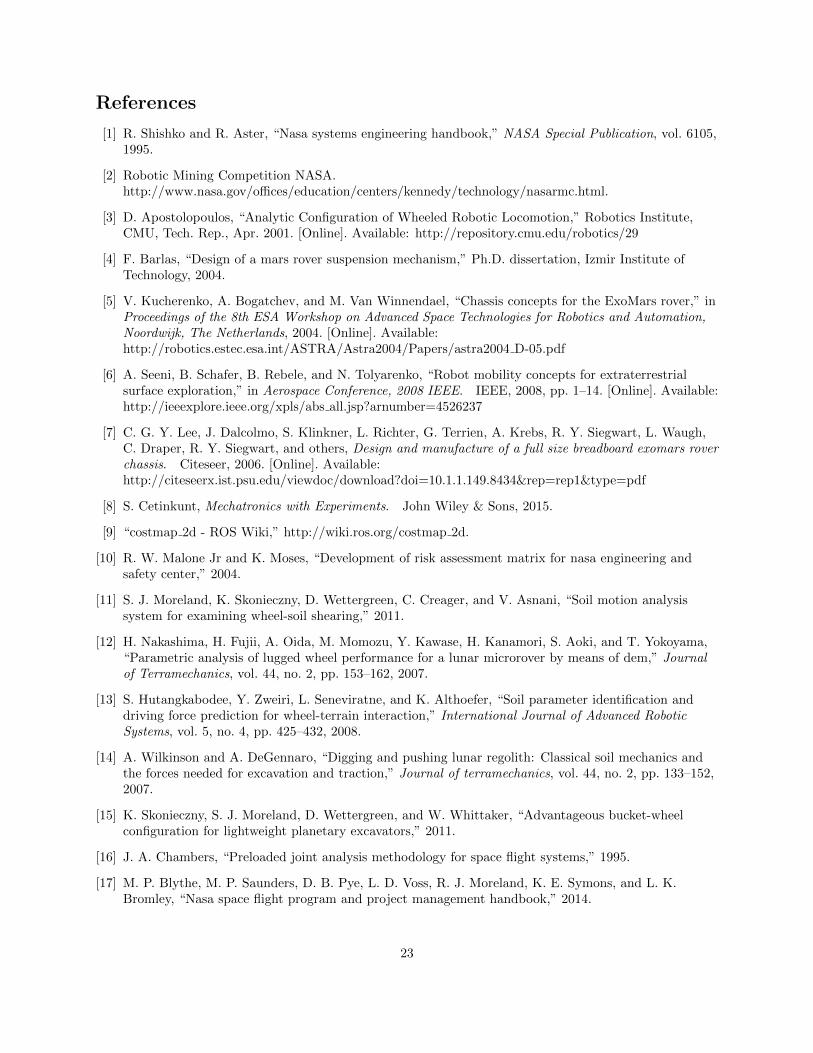
Figure 30: 2015 Expenditures
The UIC team is fortunate in that the UIC College of Engi-neering provides the bulk of the required financial support forthe year. The remaining balance required to field a miningrobot is filled through the generous donations (both monetaryand material) from sponsors such as the Sick Group, CaterpillarInc., Ability Engineering Technology Inc., and NASA providedgrants.
As seen in Figure 30, a balance of $1,944.56 remains as of thesubmission of this report. With a month left before the compe-tition, there may be several minor draws from the account dueto unforeseen purchases, but in all the initial budget estimatefor Surus closely matches the required expenditures.
20

A System Overview
Figure 31: System Diagram
21

B Program Gantt Chart
ID Task Name Duration Start Finish Predecessors Successors
Text2: No Value 5 days Mon 5/25/15 Fri 5/29/15Text3: No Value 5 days Mon 5/25/15 Fri 5/29/15
Text1: Milestone 5 days Mon 5/25/15 Fri 5/29/151 NASA Robotic Mining Competition 5 days Mon 5/25/15 Fri 5/29/15 2,3FS-30 days,4FS-30 days,5FS-15 days
Text2: Arena 55 days Wed 7/23/14 Tue 10/7/14Text3: Structure 55 days Wed 7/23/14 Tue 10/7/14
Text1: Test and Refine 55 days Wed 7/23/14 Tue 10/7/148 Allocate space for arena for autonomy testing 10 days Wed 7/23/14 Tue 8/5/14 77 Design arena for autonomy testing 15 days Wed 8/6/14 Tue 8/26/14 8 1010 Obtain materials for arena 15 days Wed 8/27/14 Tue 9/16/14 7 66 Build arena for autonomy testing 15 days Wed 9/17/14 Tue 10/7/14 10 5FF
Text2: Complete 20 days Wed 11/5/14 Tue 12/2/14Text3: No Value 20 days Wed 11/5/14 Tue 12/2/14
Text1: Test and Refine 20 days Wed 11/5/14 Tue 12/2/145 Verify autonomous functionality 20 days Wed 11/5/14 Tue 12/2/14 6FF,99FF 1FS-15 days99 Verify robot functionality 20 days Wed 11/5/14 Tue 12/2/14 96,97,98 5FF
Text2: Electronics 100 days Wed 7/23/14 Tue 12/9/14Text3: Communications 85 days Wed 7/23/14 Tue 11/18/14
Text1: Design 50 days Wed 7/23/14 Tue 9/30/1482 Design communications system, spec hardware 30 days Wed 7/23/14 Tue 9/2/14 8383 Review communications and hardware design 10 days Wed 9/3/14 Tue 9/16/14 82 8484 Submit parts list for communication equipment and 10 days Wed 9/17/14 Tue 9/30/14 83 46,40
Text1: Manufacture 35 days Wed 10/1/14 Tue 11/18/1440 Procure communications mounting material 15 days Wed 10/1/14 Tue 10/21/14 84 4246 Procure communications equipment 15 days Wed 10/1/14 Tue 10/21/14 84 4747 Assemble communications equipment 10 days Wed 10/22/14 Tue 11/4/14 46 4242 Manufacture communications mount 10 days Wed 11/5/14 Tue 11/18/14 40,47
Text3: Electronics 5 days Wed 10/29/14 Tue 11/4/14Text1: Assemble 5 days Wed 10/29/14 Tue 11/4/14
98 Assemble electronics components 5 days Wed 10/29/14 Tue 11/4/14 97FF,96FF 99Text3: Motor Controllers 40 days Wed 9/10/14 Tue 11/4/14
Text1: Design 20 days Wed 9/10/14 Tue 10/7/1485 Determine proper specs for motor controllers 10 days Wed 9/10/14 Tue 9/23/14 65,93,69 8686 Review motor controller choice 5 days Wed 9/24/14 Tue 9/30/14 85 8787 Submit parts list for motor controller 5 days Wed 10/1/14 Tue 10/7/14 86 49,44
Text1: Manufacture 20 days Wed 10/8/14 Tue 11/4/1444 Procure motor controller mounting material 15 days Wed 10/8/14 Tue 10/28/14 87 4549 Procure motor controllers 15 days Wed 10/8/14 Tue 10/28/14 87 4545 Manufacture motor controller mounts 5 days Wed 10/29/14 Tue 11/4/14 44,49
Text3: Sensors 100 days Wed 7/23/14 Tue 12/9/14Text1: Design 50 days Wed 7/23/14 Tue 9/30/14
88 Determine proper specs for sensors 30 days Wed 7/23/14 Tue 9/2/14 8989 Review sensor choices 10 days Wed 9/3/14 Tue 9/16/14 88 9090 Submit parts list for sensors 10 days Wed 9/17/14 Tue 9/30/14 89 51,41
Text1: Manufacture 50 days Wed 10/1/14 Tue 12/9/1441 Procure sensor mounting material 15 days Wed 10/1/14 Tue 10/21/14 90 4351 Procure sensors 40 days Wed 10/1/14 Tue 11/25/14 90 4343 Manufacture sensor mounts 10 days Wed 11/26/14 Tue 12/9/14 41,51
Text2: Equipment 5 days Mon 5/18/15 Fri 5/22/15Text3: No Value 5 days Mon 5/18/15 Fri 5/22/15
Text1: Prep for competition 5 days Mon 5/18/15 Fri 5/22/152 Prep robot and tooling for transport to competition 5 days Mon 5/18/15 Fri 5/22/15 1
Text2: House Rental 148 days Wed 7/23/14 Fri 2/13/15Text3: No Value 148 days Wed 7/23/14 Fri 2/13/15
Text1: Prep for competition 148 days Wed 7/23/14 Fri 2/13/1526 Scout possible house locations, verify budget 20 days Wed 7/23/14 Tue 8/19/14 44 Rent house for 8 people for 7 days 10 days Mon 2/2/15 Fri 2/13/15 26 1FS-30 days
Text2: Lower Assembly 70 days Wed 7/23/14 Tue 10/28/14Text3: Drivetrain 70 days Wed 7/23/14 Tue 10/28/14
Text1: Design 35 days Wed 7/23/14 Tue 9/9/1467 Design drivetrain 20 days Wed 7/23/14 Tue 8/19/14 6868 Review drivetrain design 10 days Wed 8/20/14 Tue 9/2/14 67 6969 Submit parts list for drivetrain 5 days Wed 9/3/14 Tue 9/9/14 68 9,85
Text1: Manufacture 35 days Wed 9/10/14 Tue 10/28/149 Procure drivetrain materials 15 days Wed 9/10/14 Tue 9/30/14 69 1515 Manufacture drivetrain components 20 days Wed 10/1/14 Tue 10/28/14 9 97FF
Text3: Frame 70 days Wed 7/23/14 Tue 10/28/14Text1: Design 35 days Wed 7/23/14 Tue 9/9/14
70 Design lower assembly frame 20 days Wed 7/23/14 Tue 8/19/14 7171 Review lower assembly frame design 10 days Wed 8/20/14 Tue 9/2/14 70 7272 Submit parts list for lower assembly frame 5 days Wed 9/3/14 Tue 9/9/14 71 13
Text1: Manufacture 35 days Wed 9/10/14 Tue 10/28/1413 Procure frame materials 15 days Wed 9/10/14 Tue 9/30/14 72 1717 Manufacture frame 20 days Wed 10/1/14 Tue 10/28/14 13 97FF
Text3: Linkage 70 days Wed 7/23/14 Tue 10/28/14Text1: Design 35 days Wed 7/23/14 Tue 9/9/14
73 Design linkage 20 days Wed 7/23/14 Tue 8/19/14 7474 Review linkage design 10 days Wed 8/20/14 Tue 9/2/14 73 7575 Submit parts list for linkage design 5 days Wed 9/3/14 Tue 9/9/14 74 12
Text1: Manufacture 35 days Wed 9/10/14 Tue 10/28/1412 Procure linkage materials 15 days Wed 9/10/14 Tue 9/30/14 75 1919 Manufacture linkage 20 days Wed 10/1/14 Tue 10/28/14 12 97FF
Text3: Lower Assembly 5 days Wed 10/22/14 Tue 10/28/14Text1: Assemble 5 days Wed 10/22/14 Tue 10/28/14
97 Assemble lower assembly 5 days Wed 10/22/14 Tue 10/28/14 15FF,17FF,19FF,21FF,23FF 98FF,99Text3: Wheel 70 days Wed 7/23/14 Tue 10/28/14
Text1: Design 35 days Wed 7/23/14 Tue 9/9/1476 Design wheel 20 days Wed 7/23/14 Tue 8/19/14 7777 Review wheel 10 days Wed 8/20/14 Tue 9/2/14 76 7878 Submit parts list for wheel 5 days Wed 9/3/14 Tue 9/9/14 77 11
Text1: Manufacture 35 days Wed 9/10/14 Tue 10/28/1411 Procure wheel materials 15 days Wed 9/10/14 Tue 9/30/14 78 2121 Manufacture wheels 20 days Wed 10/1/14 Tue 10/28/14 11 97FF
Text3: Wiring 43 days Wed 7/23/14 Fri 9/19/14Text1: Design 35 days Wed 7/23/14 Tue 9/9/14
79 Create wiring layout 20 days Wed 7/23/14 Tue 8/19/14 8080 Review wiring layout 10 days Wed 8/20/14 Tue 9/2/14 79 8181 Submit parts list required for wiring 5 days Wed 9/3/14 Tue 9/9/14 80 14
Text1: Manufacture 8 days Wed 9/10/14 Fri 9/19/1414 Procure wiring materials 5 days Wed 9/10/14 Tue 9/16/14 81 2323 Run wiring 3 days Wed 9/17/14 Fri 9/19/14 14 97FF
Text2: Transportation rental 148 days Wed 7/23/14 Fri 2/13/15Text3: No Value 148 days Wed 7/23/14 Fri 2/13/15
Text1: Prep for competition 148 days Wed 7/23/14 Fri 2/13/1529 Scout possible vehicle configurations, verify budge 20 days Wed 7/23/14 Tue 8/19/14 33 Rent vehicle to transport people and equipment fo 10 days Mon 2/2/15 Fri 2/13/15 29 1FS-30 days
Text2: Upper Assembly 75 days Wed 7/23/14 Tue 11/4/14Text3: Actuators 65 days Wed 7/23/14 Tue 10/21/14
Text1: Design 35 days Wed 7/23/14 Tue 9/9/1491 Design actuator and framework 20 days Wed 7/23/14 Tue 8/19/14 9292 Review actuator framework 10 days Wed 8/20/14 Tue 9/2/14 91 9393 Submit parts list for actuator 5 days Wed 9/3/14 Tue 9/9/14 92 94,85
Text1: Manufacture 30 days Wed 9/10/14 Tue 10/21/1494 Procure actuator and framework materials 15 days Wed 9/10/14 Tue 9/30/14 93 9595 Manufacture actuator framework 15 days Wed 10/1/14 Tue 10/21/14 94 96FF
Text3: Bin 70 days Wed 7/23/14 Tue 10/28/14Text1: Design 35 days Wed 7/23/14 Tue 9/9/14
52 Design bin 20 days Wed 7/23/14 Tue 8/19/14 5353 Review bin 10 days Wed 8/20/14 Tue 9/2/14 52 6262 Submit parts list for bin 5 days Wed 9/3/14 Tue 9/9/14 53 32
Text1: Manufacture 35 days Wed 9/10/14 Tue 10/28/1432 Procure bin material 15 days Wed 9/10/14 Tue 9/30/14 62 3333 Manufacture bin 20 days Wed 10/1/14 Tue 10/28/14 32 96FF
Text3: Buckets 75 days Wed 7/23/14 Tue 11/4/14Text1: Design 35 days Wed 7/23/14 Tue 9/9/14
54 Design buckets 20 days Wed 7/23/14 Tue 8/19/14 5555 Review buckets 10 days Wed 8/20/14 Tue 9/2/14 54 6363 Submit parts list for buckets 5 days Wed 9/3/14 Tue 9/9/14 55 38
Text1: Manufacture 40 days Wed 9/10/14 Tue 11/4/1438 Procure bucket material 20 days Wed 9/10/14 Tue 10/7/14 63 3939 Manufacture bucket 20 days Wed 10/8/14 Tue 11/4/14 38 96FF
Text3: Dig Belt & Pulleys 60 days Wed 7/23/14 Tue 10/14/14Text1: Design 35 days Wed 7/23/14 Tue 9/9/14
56 Design belt and pulley system 20 days Wed 7/23/14 Tue 8/19/14 5757 Review belt and pulley system 10 days Wed 8/20/14 Tue 9/2/14 56 6464 Submit parts list for dig belt & pulleys 5 days Wed 9/3/14 Tue 9/9/14 57 34
Text1: Manufacture 25 days Wed 9/10/14 Tue 10/14/1434 Procure belt and pulleys 20 days Wed 9/10/14 Tue 10/7/14 64 3535 Assemble belt 5 days Wed 10/8/14 Tue 10/14/14 34 96FF
Text3: Dig Drivetrain 75 days Wed 7/23/14 Tue 11/4/14Text1: Design 35 days Wed 7/23/14 Tue 9/9/14
58 Design dig drivetrain 20 days Wed 7/23/14 Tue 8/19/14 5959 Review dig drivetrain 10 days Wed 8/20/14 Tue 9/2/14 58 6565 Submit parts list for dig drivetrain 5 days Wed 9/3/14 Tue 9/9/14 59 36,85
Text1: Manufacture 40 days Wed 9/10/14 Tue 11/4/1436 Procure drivetrain materials 25 days Wed 9/10/14 Tue 10/14/14 65 3737 Manufacture dig drivetrain components 15 days Wed 10/15/14 Tue 11/4/14 36 96FF
Text3: Frame 75 days Wed 7/23/14 Tue 11/4/14Text1: Design 35 days Wed 7/23/14 Tue 9/9/14
60 Design upper assembly frame 20 days Wed 7/23/14 Tue 8/19/14 6161 Review upper assembly frame 10 days Wed 8/20/14 Tue 9/2/14 60 6666 Submit parts list for upper assembly frame 5 days Wed 9/3/14 Tue 9/9/14 61 30
Text1: Manufacture 40 days Wed 9/10/14 Tue 11/4/1430 Procure frame material 15 days Wed 9/10/14 Tue 9/30/14 66 3131 Manufacture frame 25 days Wed 10/1/14 Tue 11/4/14 30
Text3: Upper Assembly 5 days Wed 10/29/14 Tue 11/4/14Text1: Assemble 5 days Wed 10/29/14 Tue 11/4/14
96 Assemble upper assembly 5 days Wed 10/29/14 Tue 11/4/14 95FF,33FF,39FF,35FF,37FF 98FF,99
Figure 32: 2014 Project Schedule
22
References
[1] R. Shishko and R. Aster, “Nasa systems engineering handbook,” NASA Special Publication, vol. 6105,1995.
[2] Robotic Mining Competition NASA.http://www.nasa.gov/offices/education/centers/kennedy/technology/nasarmc.html.
[3] D. Apostolopoulos, “Analytic Configuration of Wheeled Robotic Locomotion,” Robotics Institute,CMU, Tech. Rep., Apr. 2001. [Online]. Available: http://repository.cmu.edu/robotics/29
[4] F. Barlas, “Design of a mars rover suspension mechanism,” Ph.D. dissertation, Izmir Institute ofTechnology, 2004.
[5] V. Kucherenko, A. Bogatchev, and M. Van Winnendael, “Chassis concepts for the ExoMars rover,” inProceedings of the 8th ESA Workshop on Advanced Space Technologies for Robotics and Automation,Noordwijk, The Netherlands, 2004. [Online]. Available:http://robotics.estec.esa.int/ASTRA/Astra2004/Papers/astra2004 D-05.pdf
[6] A. Seeni, B. Schafer, B. Rebele, and N. Tolyarenko, “Robot mobility concepts for extraterrestrialsurface exploration,” in Aerospace Conference, 2008 IEEE. IEEE, 2008, pp. 1–14. [Online]. Available:http://ieeexplore.ieee.org/xpls/abs all.jsp?arnumber=4526237
[7] C. G. Y. Lee, J. Dalcolmo, S. Klinkner, L. Richter, G. Terrien, A. Krebs, R. Y. Siegwart, L. Waugh,C. Draper, R. Y. Siegwart, and others, Design and manufacture of a full size breadboard exomars roverchassis. Citeseer, 2006. [Online]. Available:http://citeseerx.ist.psu.edu/viewdoc/download?doi=10.1.1.149.8434&rep=rep1&type=pdf
[8] S. Cetinkunt, Mechatronics with Experiments. John Wiley & Sons, 2015.
[9] “costmap 2d - ROS Wiki,” http://wiki.ros.org/costmap 2d.
[10] R. W. Malone Jr and K. Moses, “Development of risk assessment matrix for nasa engineering andsafety center,” 2004.
[11] S. J. Moreland, K. Skonieczny, D. Wettergreen, C. Creager, and V. Asnani, “Soil motion analysissystem for examining wheel-soil shearing,” 2011.
[12] H. Nakashima, H. Fujii, A. Oida, M. Momozu, Y. Kawase, H. Kanamori, S. Aoki, and T. Yokoyama,“Parametric analysis of lugged wheel performance for a lunar microrover by means of dem,” Journalof Terramechanics, vol. 44, no. 2, pp. 153–162, 2007.
[13] S. Hutangkabodee, Y. Zweiri, L. Seneviratne, and K. Althoefer, “Soil parameter identification anddriving force prediction for wheel-terrain interaction,” International Journal of Advanced RoboticSystems, vol. 5, no. 4, pp. 425–432, 2008.
[14] A. Wilkinson and A. DeGennaro, “Digging and pushing lunar regolith: Classical soil mechanics andthe forces needed for excavation and traction,” Journal of terramechanics, vol. 44, no. 2, pp. 133–152,2007.
[15] K. Skonieczny, S. J. Moreland, D. Wettergreen, and W. Whittaker, “Advantageous bucket-wheelconfiguration for lightweight planetary excavators,” 2011.
[16] J. A. Chambers, “Preloaded joint analysis methodology for space flight systems,” 1995.
[17] M. P. Blythe, M. P. Saunders, D. B. Pye, L. D. Voss, R. J. Moreland, K. E. Symons, and L. K.Bromley, “Nasa space flight program and project management handbook,” 2014.
23