uhv gate valve - lesker · conversion from double acting to 3-position pneumatic actuator (see...
TRANSCRIPT

certif
ied QM-System
geprüftes QM-Syste
m
ISO 9001EN 29001
Installation, Operating, and Maintenance Instructions
Series 10.8, DN 250 - 320 (10" - 12")
VAT Vakuumventile AG, CH-9469 Haag, Switzerland Tel +41 81 771 61 61 Fax +41 81 771 48 30 [email protected] www.vatvalve.com
207442EB 2003-04-14
1/15
UHV gate valve with 3 position pneumatic actuator This manual is valid for the valve ordering numbers: 10848- . E28/48 10850- . E28/48 The respective product identification is given on each valve in the following or in a similar way:
made in SwitzerlandFabrication No.: patented
96
F10 – . . . . . / . .108 . . – . . . . – . . . .
Explanation of symbols:
Read declaration carefully before you start any other action!
Keep body parts and objects away from the valve opening!
Attention!
Hot surfaces; do not touch!
Product is in conformity with EC guidelines, if applicable!
Loaded springs and/or air cushions are potential hazards!
Disconnect electrical power and compressed air lines. Do not touch parts under voltage!
Wear gloves!
Read these «Installation, Operating & Maintenance Instructions» and the enclosed «General Safety Instructions» carefully before you start any other action!

certif
ied QM-System
geprüftes QM-Syste
m
ISO 9001EN 29001
Installation, Operating, and Maintenance Instructions
Series 10.8, DN 250 - 320 (10" - 12")
VAT Vakuumventile AG, CH-9469 Haag, Switzerland Tel +41 81 771 61 61 Fax +41 81 771 48 30 [email protected] www.vatvalve.com
207442EB 2003-04-14
2/15
Imprint:
VAT Vakuumventile AG, CH-9469 Haag, Switzerland Manufacturer
Website www.vatvalve.com
Phone +41 81 771 61 61
Fax +41 81 771 48 30
Email [email protected]
Publisher VAT Vakuumventile AG, CH-9469 Haag, Switzerland
Editor VAT Vakuumventile AG, CH-9469 Haag, Switzerland
Print VAT Vakuumventile AG, CH-9469 Haag, Switzerland
Copyright © VAT Vakuumventile AG 2008 No part of these Instructions may be reproduced in any way (photocopies, microfilms or any
other reproduction processes) nor may it be manipulated with electronic systems, duplicated or distributed without written permission from VAT. Offenders are liable to pay damages.
The original VAT firmware and updated state of the art versions of the VAT firmware are
intended for use with VAT products. The VAT firmware contains a limited, time unlimited user license. The VAT firmware may not be used for purposes other than those intended nor is it permitted to make copies of the VAT firmware. In particular, it is strictly forbidden to give copies of the VAT firmware to other people.
The use of trade names, brand names, trademarks, etc. in these Instructions does not entitle
third parties to consider these names to be unprotected and to use them freely. This is in accordance with the meaning of the laws and acts covering brand names and trademarks.
certif
ied QM-System
geprüftes QM-Syste
m
ISO 9001EN 29001
Installation, Operating, and Maintenance Instructions
Series 10.8, DN 250 - 320 (10" - 12")
VAT Vakuumventile AG, CH-9469 Haag, Switzerland Tel +41 81 771 61 61 Fax +41 81 771 48 30 [email protected] www.vatvalve.com
207442EB 2003-04-14
3/15
Intended use of product Use product for vacuum applications under the conditions indicated in the chapter «Technical data» only! Other applications are only allowed with the written permission of VAT. Technical data Pressure range 1 x 10⁻¹⁰ mbar to 1.2 bar (abs)
Differential pressure on the gate ≤ 1.2 bar in either direction
Differential pressure at opening ≤ 30 mbar
Admissible temperature: Valve ≤ 250°C open, 200°C closed Pneumatic actuator ≤ 200°C Position indicator ≤ 80°C Solenoid ≤ 50°C
Position indicator: contact rating 5 A / 250 V AC, 3 A / 50 V DC
Solenoid see tag on solenoid
Mounting position actuator downwards not allowed
Further data according to VAT catalogue «Vacuum Valves 2004».

certif
ied QM-System
geprüftes QM-Syste
m
ISO 9001EN 29001
Installation, Operating, and Maintenance Instructions
Series 10.8, DN 250 - 320 (10" - 12")
VAT Vakuumventile AG, CH-9469 Haag, Switzerland Tel +41 81 771 61 61 Fax +41 81 771 48 30 [email protected] www.vatvalve.com
207442EB 2003-04-14
4/15
Installation into the vacuum system The valve seat side is indicated by the symbol "∇" on the connection flange. Admissible forces Forces from evacuating the system, from the weight of other components, and from baking can lead to deformation of the valve body and to malfunction of the valve. The stress has to be relieved by suitable means, e.g. bellows sections. The following forces are admissible:
DN (nom. I.D.) Axial tensile or compressive force «FA»
Bending moment «M»
mm inch N lbf Nm lbf • ft
250 10 3430 770 196 140
320 12 4000 900 300 220
If a combination of both forces («FA» and «M») occurs, the values mentioned above are invalid. Please contact VAT for more information.
Compressed air connection
Connect compressed air only if - valve has been installed into the vacuum system - moving parts cannot be touched
With solenoid: Connect compressed air to IN (internal thread R 1/8“, 1/8“ NPT for USA) Without solenoid: Connect compressed air to OPEN and CLOSE (internal thread 1/8")
Solenoid delivered separately:
Compressed air connection on pneumatics cylinder: Internal thread 1/8 "
Compressed air to connection <A>: Valve opens
Compressed air to connection <B>: Valve closes
Compressed air pressure (min. - max. overpressure): 5 - 7 bar / 70 - 100 psig
Use only clean, dry or slightly oiled air!
FA M

certif
ied QM-System
geprüftes QM-Syste
m
ISO 9001EN 29001
Installation, Operating, and Maintenance Instructions
Series 10.8, DN 250 - 320 (10" - 12")
VAT Vakuumventile AG, CH-9469 Haag, Switzerland Tel +41 81 771 61 61 Fax +41 81 771 48 30 [email protected] www.vatvalve.com
207442EB 2003-04-14
5/15
Electrical connection
Do not touch electrical parts under voltage!
Connect electrical power only if - valve has been installed into the vacuum system - moving parts cannot be touched
Verify that mains voltage matches voltage stated on the solenoid! Sockets for position indicator and solenoid are supplied with the valve.
Wire solenoid and position indicator according to the following diagrams:
Standard solenoids Position indicator for three positions
Main cylinder MV1 and auxiliary cylinder MV2 for third position (see drawing on page 5)
MV
MV
2
1
1
2
power 2
1
1
2
Lz
Lg
Lo
3
4
5
6
2
1
6
5
4 3
2
1
MV = coils of solenoid Lo = position indicator «open» Lg = position indicator «closed» Lz = position indicator for the intermediate position
Solenoid MV1 MV2
Valve position: open Intermediate position closed
1 1 0
1 0 1
1 = coil of solenoid supplied with current 0 = coil of solenoid not supplied with current

certif
ied QM-System
geprüftes QM-Syste
m
ISO 9001EN 29001
Installation, Operating, and Maintenance Instructions
Series 10.8, DN 250 - 320 (10" - 12")
VAT Vakuumventile AG, CH-9469 Haag, Switzerland Tel +41 81 771 61 61 Fax +41 81 771 48 30 [email protected] www.vatvalve.com
207442EB 2003-04-14
6/15
Operation Normal operation Valve is opened and closed by means of compressed air. Admissible temperature See «Technical data»! Compressed air failure Valve closed: valve remains closed Valve open: Valve position is undefined, depending on mounting Valve intermediate position: Valve position is undefined, depending on mounting position At compressed air return, the valve gate moves to the present position. Power failure Standard solenoid: valve closes Emergency operation at power failure In case of a power failure, the valve can be actuated manually if compressed air is available.
Standard solenoid
Press both push-buttons MV1 + MV2: valve opens Release both push-buttons MV1 + MV2: valve closes Press only push-button MV1: Valve gate moves to the intermediate position
certif
ied QM-System
geprüftes QM-Syste
m
ISO 9001EN 29001
Installation, Operating, and Maintenance Instructions
Series 10.8, DN 250 - 320 (10" - 12")
VAT Vakuumventile AG, CH-9469 Haag, Switzerland Tel +41 81 771 61 61 Fax +41 81 771 48 30 [email protected] www.vatvalve.com
207442EB 2003-04-14
7/15
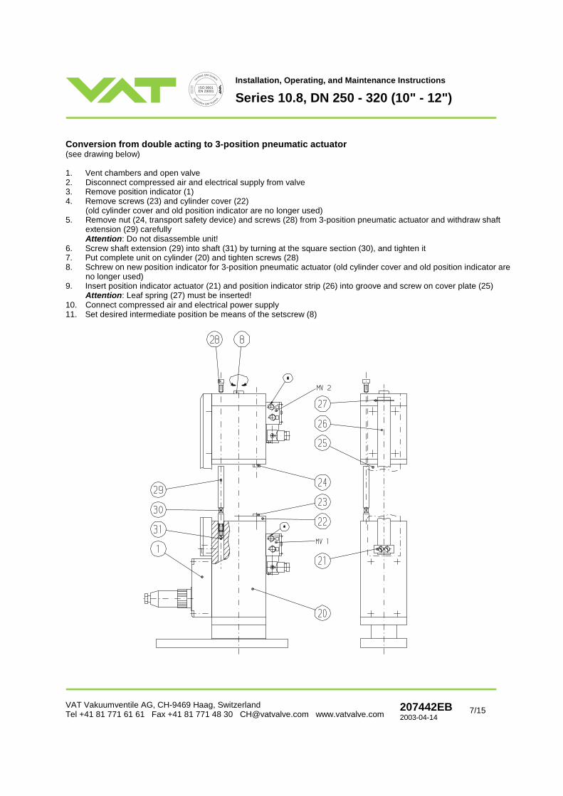
Conversion from double acting to 3-position pneumatic actuator (see drawing below) 1. Vent chambers and open valve 2. Disconnect compressed air and electrical supply from valve 3. Remove position indicator (1) 4. Remove screws (23) and cylinder cover (22)
(old cylinder cover and old position indicator are no longer used) 5. Remove nut (24, transport safety device) and screws (28) from 3-position pneumatic actuator and withdraw shaft
extension (29) carefully Attention: Do not disassemble unit!
6. Screw shaft extension (29) into shaft (31) by turning at the square section (30), and tighten it 7. Put complete unit on cylinder (20) and tighten screws (28) 8. Schrew on new position indicator for 3-position pneumatic actuator (old cylinder cover and old position indicator are
no longer used) 9. Insert position indicator actuator (21) and position indicator strip (26) into groove and screw on cover plate (25)
Attention: Leaf spring (27) must be inserted! 10. Connect compressed air and electrical power supply 11. Set desired intermediate position be means of the setscrew (8)

certif
ied QM-System
geprüftes QM-Syste
m
ISO 9001EN 29001
Installation, Operating, and Maintenance Instructions
Series 10.8, DN 250 - 320 (10" - 12")
VAT Vakuumventile AG, CH-9469 Haag, Switzerland Tel +41 81 771 61 61 Fax +41 81 771 48 30 [email protected] www.vatvalve.com
207442EB 2003-04-14
8/15
Conversion of a manual actuator to a 3-position pneumatic actuator (see following drawing) 1. Disassembly of manual actuator 1.1 Vent chambers and open valve 1.2 Loosen screw (35) through access hole (37) 1.3 Remove screws (33) 1.4 Withdraw manual actuator (36) carefully 2. Assembly of actuator unit «A»: 2.1 Valve is in open position 2.2 Remove nuts (34) 2.3 Remove cylinder cover (22) and screws (23), but do not remove O-ring from cover
Attention! Do not disassemble remaining unit 2.4 Remove guiding shafts (31) from unit «A» and insert them into the bellows end piece (38) of the valve by turning at
the squared sections (39) 2.5 Put actuator unit (A) in place 2.6 Tighten screw of piston (32) until resistance is noticeable 2.7 Put cylinder cover (22) in place and fix it by means of screws (23) 2.8 Close valve by means of compressed air (approx. 3 bar) 2.9 Disconnect compressed air supply and vent cylinder interior completely 2.10 Remove cylinder cover (22) 2.11 Tighten screw of piston (32) until valve unlocks (audible) 2.12 Loosen screw of piston (32) by ½ turn 2.13 Put cylinder cover (22) in place and fix it by means of screws (23) 2.14 Close valve by means of compressed air (approx. 3 bar) (Lever audible over dead center) 2.15 Measure opening pressure (should be between 1.0 and 1.3 bar in order to keep the valve ub locked position in the
event of compressed air failure) 2.16 If the opening pressure is below 1.0 bar: Loosen screw of piston (32) by 1/8 turn 2.17 If the opening pressure exceeds 1.3 bar: Tighten screw of piston (32) by 1/8 turn 2.18 Attention! Before disassembling the cylinder cover always disconnect compressed air supply and vent cylinder
interior completely 3. Assembly of 3-position pneumatic actuator «B»: 3.1 Remove cylinder cover (22) (is no longer necessary) 3.2 Remove nuts (24, transport safety screws) and screws (28) from 3-position pneumatic actuator and withdraw shaft
extension (29) Attention! Do not disassemble unit
3.3 Insert shaft extensions (29) into shafts (31) by turning at the squared sections (30) and tighten them 3.4 Put complete unit (B) on cylinder (20) and tighten screws (28). Make sure that the O-ring (40) has been installed. 3.5 Connect compressed air and power 3.6 Adjust desired intermediate position by means of screw (8)

certif
ied QM-System
geprüftes QM-Syste
m
ISO 9001EN 29001
Installation, Operating, and Maintenance Instructions
Series 10.8, DN 250 - 320 (10" - 12")
VAT Vakuumventile AG, CH-9469 Haag, Switzerland Tel +41 81 771 61 61 Fax +41 81 771 48 30 [email protected] www.vatvalve.com
207442EB 2003-04-14
9/15
Adjustment of the intermediate position a) with solenoids: b) without solenoids: - MV1: coils of solenoids supplied with electrical power - Cylinder «A»: compressed air to «OPEN» - MV2: coils of solenoids not supplied with electrical power - Cylinder «B»: compressed air to «MID» - Adjust the desired intermediate position
by means of the adjustment screw (8) - Adjust the desired intermediate position
by means of the adjustment screw (8) Attention: If the compressed air pressure applied for adjusting the intermediate position differs from that specified in the
chapter «Compressed air pressure» (page 4) it may happen that the carrier nut inside the actuator disengages from the adjustment screw (8). The same problem can occur when the adjustment screw (8) is still being turned in counter-clockwise direction after the mechanism has reached the closed position.
In order to recapture the carrier nut, please follow the instructions below:
1. Supply the inlet «OPEN» with 1 bar / 15 psig of compressed air 2. Turn the adjustment screw (8) in clockwise direction until the carrier nut is completely recaptured
(We recommend to carry out 20 full turns!) 3. Adjust the intermediate position according to above instructions [ a) or b) ]

certif
ied QM-System
geprüftes QM-Syste
m
ISO 9001EN 29001
Installation, Operating, and Maintenance Instructions
Series 10.8, DN 250 - 320 (10" - 12")
VAT Vakuumventile AG, CH-9469 Haag, Switzerland Tel +41 81 771 61 61 Fax +41 81 771 48 30 [email protected] www.vatvalve.com
207442EB 2003-04-14
10/15
Preventive maintenance Under clean operating conditions, the valve does not require any maintenance during the specified cycle life.
Maintenance Replacement of actuator/mechanism assembly The figures in brackets refer to the drawing on page 11
- Vent chambers and open valve - Disconnect compressed air and electrical power from valve - Remove bonnet screws (61) in crosswise order - Withdraw actuator/mechanism assembly carefully from body - Check and clean sealing surfaces of bonnet and valve seat - Put new bonnet seal (60) on bonnet - Reassemble in reverse direction
Note! Tighten screws in crosswise order! Torque: 40 Nm / 30 lbf . ft Replacement of gate seal
- Remove actuator/mechanism assembly as described in the section «Replacement of actuator/mechanism assembly» - Stick a needle into the gate O-ring at the vent slots and withdraw O-ring from groove Attention: Be careful not to damage the sealing surface! - Check and clean sealing surface of valve seat - Install new gate O-ring Attention: Press O-ring uniformly in crosswise order (diagonal) into groove

certif
ied QM-System
geprüftes QM-Syste
m
ISO 9001EN 29001
Installation, Operating, and Maintenance Instructions
Series 10.8, DN 250 - 320 (10" - 12")
VAT Vakuumventile AG, CH-9469 Haag, Switzerland Tel +41 81 771 61 61 Fax +41 81 771 48 30 [email protected] www.vatvalve.com
207442EB 2003-04-14
11/15
Spare parts

certif
ied QM-System
geprüftes QM-Syste
m
ISO 9001EN 29001
Installation, Operating, and Maintenance Instructions
Series 10.8, DN 250 - 320 (10" - 12")
VAT Vakuumventile AG, CH-9469 Haag, Switzerland Tel +41 81 771 61 61 Fax +41 81 771 48 30 [email protected] www.vatvalve.com
207442EB 2003-04-14
12/15
The item numbers refer to the drawing on page 11
Item Description DN Part No. Air connection kit (standard without solenoid)
Seal kit, 250 82689-R1 Item Description DN Qty. Part No.
Consisting of: - O-ring (21/31) - Bonnet seal (60)
320 86835-R1 44 Pneumatic connection kit
250-320
2 94827-R1
21/31 Gate O-ring 250 N-5102-378
266.07 x 5.33 316.87 x 6.99
320 N-5102-454
21/30 1 Set of 24 pcs 250 N-6121-072
locking balls 24 pcs 320 N-6121-086
60 Bonnet seal 250 77876-01
320 93243-01
Solenoid kit: (standard)
Item Description Qty. Part No.
Solenoid kit 2 94800-R1
43/1 Solenoid 2 N-7557-018 *)
43/10 Plug 2 N-8501-400 ..... *) Specify voltage! (e.g. N-7557-018-220V 50Hz)

certif
ied QM-System
geprüftes QM-Syste
m
ISO 9001EN 29001
Installation, Operating, and Maintenance Instructions
Series 10.8, DN 250 - 320 (10" - 12")
VAT Vakuumventile AG, CH-9469 Haag, Switzerland Tel +41 81 771 61 61 Fax +41 81 771 48 30 [email protected] www.vatvalve.com
207442EB 2003-04-14
13/15
3 position indicator kit: DN 250 3 position indicator kit: DN 320
OPENCLOSED
42/2
42/3+4
42/1
42/6
Item Description Qty. Part No. Item Description Qty. Part No. Position indicator kit 1 81085-R1 Position indicator kit 1 92743-R1 42/1 Position indicator 1 73656-R1 42/1 Position indicator 1 73656-R1 42/2 Slider 1 73638-R1 42/12 Slider 1 74925-R2 42/3 Strip 1 70987-01 42/4 Driving pin 2 70988-01 42/6 Plug 1 N-8504-002 42/6 Plug 1 N-8504-002 Trouble shooting Valve does not close/open: Power available? Compressed air available? Solenoid defective? Check voltage! Check air pressure! Leak at gate: Clean valve seat and gate! Replace gate, if damaged! Correct air pressure? Leak at body: Flanges leaktight? Replace bonnet seal!

certif
ied QM-System
geprüftes QM-Syste
m
ISO 9001EN 29001
Installation, Operating, and Maintenance Instructions
Series 10.8, DN 250 - 320 (10" - 12")
VAT Vakuumventile AG, CH-9469 Haag, Switzerland Tel +41 81 771 61 61 Fax +41 81 771 48 30 [email protected] www.vatvalve.com
207442EB 2003-04-14
14/15
Global leak at bonnet seal after heating the valve! Due to a possible settlement of screw and VATSEAL it could happen that after a heat up and cool down procedure the bonnet seal becomes slight leaky. In this case please check the torque (see below) of bonnet screw (see page 11 item 61) and tighten the screws if necessary with a torque wrench. Remark: Do tight screws crosswise! Necessary torque of screws is for DN 250 and DN 320; 40 Nm / 30 lbf . ft. Repairs Contact VAT for repairs or maintenance. The fabrication No. (F10- . . . . . / . . ) marked on the valve body has always to be specified. It has to be individually decided whether the work can be performed by the customer or has to be carried out by VAT. All supplies (e. g. compressed air, electrical power) have to be disconnected for removal/installation of the valve from/into the system.
Even with disconnected supply, loaded springs and/or air cushions in cylinders can be potential hazards.
Keep fingers and objects away from the valve opening!
Products returned to VAT for repair have to be free of harmful substances such as e.g. toxical, caustic or microbiological ones. For radioactively contaminated products the customer has to fill in the VAT form «Contamination and Radiation Report» and to send it with the product. The form is available at VAT. The maximum permissible values indicated in the form must not be exceeded.

certif
ied QM-System
geprüftes QM-Syste
m
ISO 9001EN 29001
Installation, Operating, and Maintenance Instructions
Series 10.8, DN 250 - 320 (10" - 12")
VAT Vakuumventile AG, CH-9469 Haag, Switzerland Tel +41 81 771 61 61 Fax +41 81 771 48 30 [email protected] www.vatvalve.com
207442EB 2003-04-14
15/15
Warranty Each product sold by VAT Vakuumventile AG (VAT) is warranted to be free from the manufacturing defects that adversely affect the normal functioning thereof during the one-year period immediately following delivery thereof by VAT, provided that the same is properly operated under conditions of normal use and that regular, periodic maintenance and service is performed or replacements made, in accordance with the instructions provided by VAT. The foregoing warranty shall not apply to any product or component that has been repaired or altered by anyone other than an authorized VAT representative or that has been subject to improper installation or abuse, misuse, negligence or accident. VAT shall not be liable for any damage, loss, or expense, whether consequential, special, incidental, direct or otherwise, caused by, arising out of or connected with the manufacture, delivery (including any delay in or failure to deliver), packaging, storage or use of any product sold or delivered by VAT shall fail to conform to the foregoing warranty or to the description thereof contained herein, the purchaser thereof, as its exclusive remedy, shall upon prompt notice to VAT of any such defect or failure and upon the return of the product, part or component in question to VAT at its factory, with transportation charges prepaid, and upon VAT's inspection confirming the existence of any defect inconsistent with said warranty or any such failure, be entitled to have such defect or failure cured at VAT's factory and at no charge therefor, by replacement or repair of said product, as VAT may elect. VAT MAKES NO WARRANTY OR REPRESENTATION OF ANY KIND, EXPRESS OR IMPLIED, (INCLUDING NO WARRANTY OR MERCHANTABILITY), EXCEPT FOR THE FOREGOING WARRANTY AND THE WARRANTY THAT EACH PRODUCT SHALL CONFORM TO THE DESCRIPTION THEREOF CONTAINED HEREIN, and no warranty shall be implied by law.
Furthermore, the «Terms of sale» at the back of the price list are applicable.