uhlig's corrosion handbook (revie/corrosion handbook 3e) || localized corrosion of iron and...
TRANSCRIPT

47LOCALIZED CORROSION OF IRON AND STEEL
I. MATSUSHIMA*Maebashi Institute of Technology, Maebashi, Japan
A. General characteristics
B. Macrogalvanic cells
B1. Types of macrogalvanic cells
B2. Bimetallic contact
B3. Localized corrosion at welded joints
B4. Discontinuous surface films
B5. Differential aeration
B6. Differential pH
C. Localized Corrosion by Other Causes
C1. Other types of macrogalvanic cells
C2. Nongalvanic types
D. Maximum Possible Penetration Rate
References
A. GENERAL CHARACTERISTICS
Localized corrosion of iron and steel, typically pitting,
usually occurs by the action of macrogalvanic cells. In a
macrogalvanic cell, the anodic and cathodic areas are mac-
roscopic, and their locations are fixed, whereas in a micro-
galvanic cell the anodic and cathodic sites are microscopic
and their locations change randomly with time. Relatively
small fixed anodic areas surrounded by or connected to
relatively large cathodic areas undergo corrosion. Unlike
pitting of passive metals, such as stainless steels, where
localized breakdown of passivity and the resulting formation
of passive–active cells of large potential difference cause
deep pits, localized corrosion of iron and steel tends to be
shallow in most cases, as the potential difference of various
macrogalvanic cells is not as large.
In certain situations, the anodic area of macrogalvanic
cells corrodes more or less evenly, resulting in localized
corrosion, but in some other situations, specific sites in an
anodic area corrode preferentially due to inhomogeneity of
the metal surface and/or the environment towhich the anodic
area is exposed. For example, the anodic areas of differential
aeration cells in steel pipe buried in the ground usually form
discrete pits at localized sites where the metal/soil contact
resistance is lower than at the rest of the anodic areas.
Localized corrosion of iron and steel may occur by the
severe corrosive action of the environment concentrated at
specific sites without the formation of macrogalvanic cells.
The formation of deep pits in cylinder liners (coolant side) of
diesel engines by cavitation–erosion under corrosive action
is a typical example [1].
B. MACROGALVANIC CELLS
B1. Types of Macrogalvanic Cells
The macrogalvanic cells that frequently cause localized
corrosion in steel in service are commonly formed by bime-
tallic contact, an inhomogeneous steel matrix (typically at
welded joints), discontinuous surface films, differential aer-
ation, and differential pH caused by combinations of an
alkaline (pH>�10) and a near-neutral (pH in the range of
5–9) environment that leads to the formation of passive–
active cells. An alkaline environment is typically provided by
mortar or concrete.
B2. Bimetallic Contact
Bimetallic corrosion of steel that occurs when the steel is
coupled to a more noble metal usually takes the form of
Uhlig’s Corrosion Handbook, Third Edition, Edited by R. Winston Revie
Copyright � 2011 John Wiley & Sons, Inc.
*Deceased.
615
general attack over the steel surface. If the steel in bimetallic
contact with a noble metal is coated with organic materials,
such as paint, localized corrosion, commonly in the form of
severe pitting, occurs at holidays (i.e., defects) in the coating
because of the large cathode–anode area ratio.
In one case, 350-mm-diameter sewage piping of 7.9mm
wall thickness, internally coated with coal tar epoxy resin,
was perforated in 7 months, and the penetration rate was as
high as 13.5mm/year (530mdd) [2]. The internal surface of
the piping at each butt-welded joint was lined with 400-mm-
wide type 304 stainless steel instead of the resin paint coating
that would be damaged by welding. The localized attack
apparently proceeded at a coating holiday. Thus, the cath-
ode–anode area ratio was extremely large. In addition, the
specific resistance of the sewagewas low, 60W � cm, allowing
the flow of large galvanic current.
Bimetallic contact tends to accelerate localized attack
caused by some other types of macrogalvanic cells. For
example, localized corrosion at welds proceeds more rapidly
when a more noble metal is coupled, because the resulting
shift of the electrode potential of the anodic welds in the
noble direction causes a higher corrosion rate of the welds
and much deeper localized attack.
B3. Localized Corrosion at Welded Joints
When the weld metal and/or the heat-affected zone (HAZ)
are less noble than the steel (parent metal), the former
corrodes selectively. Since both are ferrous metals, the
difference in the open-circuit potential between the anode
and the cathode would not be large, most often a few
hundredths of a volt, but the penetration rate could be high
because a small shift of the potential of the anode in the noble
direction causes a large increase of the dissolution rate due to
the small Tafel slope of the anodic polarization curve for steel
(see Section D in this chapter).
As mentioned in Section C3 in Chapter 44, the welded
seam of electric resistance welded (ERW) pipe is susceptible
to groove corrosion. With a potential difference of �30mV,
the maximum penetration rate could be as high as 10mm/
year (400mpy), a rate of 1–3mm/year (40–120mpy) being
quite common. In ERW pipes developed to resist groove
corrosion, the potential difference is practically nil [3].
In welded joints, the weld metal and/or HAZ corrodes
selectively if it is less noble than the parent metal, which is
commonly much larger in surface area than the weld metal
and HAZ. The corrosion potentials of the welding materials
are almost the same as those of the parent metals but
frequently are not exactly the same. Usitalo [4] reported a
maximum of 40mV less noble potential for the welding
materials than for the steel plates for shipbuilding. The
potential of steel tends to shift in the active direction as a
result of the thermal cycle during welding operations, mak-
ing the HAZ less noble than the parent metal.
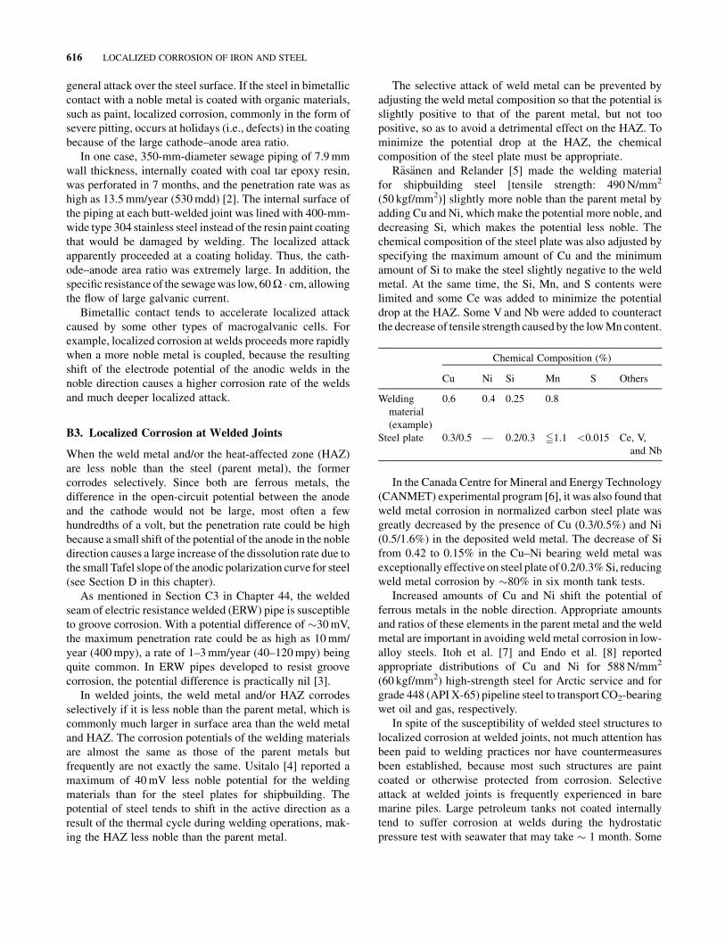
The selective attack of weld metal can be prevented by
adjusting the weld metal composition so that the potential is
slightly positive to that of the parent metal, but not too
positive, so as to avoid a detrimental effect on the HAZ. To
minimize the potential drop at the HAZ, the chemical
composition of the steel plate must be appropriate.
R€as€anen and Relander [5] made the welding material
for shipbuilding steel [tensile strength: 490N/mm2
(50 kgf/mm2)] slightly more noble than the parent metal by
adding Cu and Ni, which make the potential more noble, and
decreasing Si, which makes the potential less noble. The
chemical composition of the steel plate was also adjusted by
specifying the maximum amount of Cu and the minimum
amount of Si to make the steel slightly negative to the weld
metal. At the same time, the Si, Mn, and S contents were
limited and some Ce was added to minimize the potential
drop at the HAZ. Some V and Nb were added to counteract
the decrease of tensile strength caused by the lowMncontent.
Chemical Composition (%)
Cu Ni Si Mn S Others
Welding
material
(example)
0.6 0.4 0.25 0.8
Steel plate 0.3/0.5 — 0.2/0.3 51.1 <0.015 Ce, V,
and Nb
In the Canada Centre for Mineral and Energy Technology
(CANMET) experimental program [6], it was also found that
weld metal corrosion in normalized carbon steel plate was
greatly decreased by the presence of Cu (0.3/0.5%) and Ni
(0.5/1.6%) in the deposited weld metal. The decrease of Si
from 0.42 to 0.15% in the Cu–Ni bearing weld metal was
exceptionally effective on steel plate of 0.2/0.3%Si, reducing
weld metal corrosion by �80% in six month tank tests.
Increased amounts of Cu and Ni shift the potential of
ferrous metals in the noble direction. Appropriate amounts
and ratios of these elements in the parent metal and the weld
metal are important in avoiding weld metal corrosion in low-
alloy steels. Itoh et al. [7] and Endo et al. [8] reported
appropriate distributions of Cu and Ni for 588N/mm2
(60 kgf/mm2) high-strength steel for Arctic service and for
grade 448 (API X-65) pipeline steel to transport CO2-bearing
wet oil and gas, respectively.
In spite of the susceptibility of welded steel structures to
localized corrosion at welded joints, not much attention has
been paid to welding practices nor have countermeasures
been established, because most such structures are paint
coated or otherwise protected from corrosion. Selective
attack at welded joints is frequently experienced in bare
marine piles. Large petroleum tanks not coated internally
tend to suffer corrosion at welds during the hydrostatic
pressure test with seawater that may take � 1 month. Some
616 LOCALIZED CORROSION OF IRON AND STEEL

studies have been made of ships and offshore structures for
Arctic service, where paint coatings are prone to severe
mechanical damage by the collision of ice, and of oil and
gas pipelines, to which internal coatings are not applied.
B4. Discontinuous Surface Films
A typical example of localized corrosion under discontinuous
surface films is pitting of mill-scaled steel plate exposed to
water. Mill scale formed on the steel surface by oxidation
duringhot rollingat thesteelmill isnot continuousandexposes
the underlying steel to the environment at discontinuities or
defects. Because the mill-scaled steel surface has a potential
much more noble than the exposed steel, macrogalvanic cells
are formed between them: the large area ofmill-scaled surface
being the cathode and the small exposed areas being the anode.
Whenmill-scaled steel is exposed to seawater, the penetration
rate at the exposed small areas can be a fewmillimeters a year.
For more details, see Section B3 in Chapter 45.
Steel is seldom used with mill scale, which is removed by
either acid pickling or blasting, and the steel is then painted,
metal plated, or otherwise protected before use in corrosive
environments. When mill-scaled steel is used for large
petroleum tanks, pitting may result when it is exposed to
the seawater used for the hydrostatic pressure test at the end
of construction or to brine precipitated from the stored
petroleum.
Ifmill-scaled steel plates for construction of ships or tanks
are stored outdoors for an extended period (e.g., 6 months),
pitting corrosionmay occur, especiallywhen they are stacked
without proper separation between them to allow drying.
Rainwater penetrates between the plates and remains there,
causing pitting. In one case [9], mill-scaled steel plate used
for ship construction corroded along grooves, following the
pattern of discontinuities in mill scale resulting from stress
concentrations during service.
Steel that is corroded in water and covered with corrosion
products may undergo localized corrosion if the corrosion
products are removed repeatedly from a fixed area of rela-
tively small size. Corrosion product films protect the under-
lying steel from corrosion to some extent by acting as a
barrier layer against the corrosive environment. If this barrier
layer is damaged at a fixed area repeatedly, so that the steel
surface is exposed to the environment, the penetration rate at
the exposed area increases. Because the surface covered with
corrosion products tends to be more noble than the exposed
steel, the former acts as the cathode of the macrogalvanic
cell. When a piece of mild steel was totally immersed in
artificial seawater and the corrosion product film at a fixed
small area was removed once a day using a wooden spatula,
the penetration at that area in three months was 0.14mm,
while the average penetration was 0.043mm [10]. More
frequent removal of the corrosion product film would have
resulted in much larger localized penetration.
The waterside (inside) surface of boiler tubes, reacting
with the hot boiler water, develops an Fe3O4 film that
protects the tubes from further corrosion. Should the film
be damaged locally, either chemically or mechanically,
pitting corrosion results at the localized areas. Dissolved
oxygen, if present, accelerates the localized attack, possibly
because the large surrounding areas with intact Fe3O4 film
act as the cathode.
B5. Differential Aeration
A typical example of localized corrosion caused by differ-
ential aeration in water is associated with the formation of
tubercles. The steel surface under a tubercle receiving a poor
supply of dissolved oxygen is the anode, and the surrounding
area of better oxygen supply is the cathode. As stated in
Section C2 in Chapter 44, the penetration rate in water pipe
carrying city water having a resistivity in the range of
5000–6000W � cm can be a maximum of 0.3mm/year [11].
Assuming an average pipe corrosion rate of 0.1mm/year, the
cathode area surrounding a tubercle is about three times that
of the anode area. The penetration rate under a tuberclewould
be larger if the resistivity of the water were lower, although a
low resistivity does not necessarily favor the formation of
tubercles.
Waterline attack occurs in steel plate or pipe that extends
vertically from underwater to air. It is localized corrosion
damage at the water–air interface and can be explained in
terms of differential aeration caused by limited oxygen
supply to the area covered by a thicker corrosion product
film at the waterline.
If a buried steel pipe passes through two different soils,
onewith good aeration, such as sand, and the otherwith poor
aeration, such as clay, a differential aeration cell is set up.
The part of the pipe in well-aerated soil is the cathode, and
the part in poorly aerated soil is the anode. The corrosion
current of the cell leaves the anode at discrete points of low
pipe-to-soil resistance, resulting in deep pits. The rest of the
anode section of the pipe may corrode, but at lower pen-
etration rates.
In water of a given dissolved oxygen concentration, the
supply of oxygen to the metal surface is greater at higher
water velocity relative to the metal surface. Corrosion of
the cast iron casing of seawater pumps is accelerated by
differential aeration near the center, where the water
velocity is much lower than at the peripheral area. In one
case, the depth of corrosion (graphitic corrosion)* near the
center was� 2mm after 4600 h of operation, corresponding
*A type of corrosion that occurs mainly in gray cast iron, composed of iron
(ferrite) and graphite flakes. In the corroded layer, corrosion products of iron
cement together the residual graphite flakes and form a solid layer of low
ductility without apparent reduction in thickness. It occurs in some soils or
waters and eventually penetrates the total thickness.
MACROGALVANIC CELLS 617
to a corrosion rate of 3.8mm/year (150mpy), in contrast to
the corrosion rate of 0.8mm/year (32mpy) at the peripheral
area [12].
B6. Differential pH
Steel is passivated in alkaline environments (above a pH of
� 10) and assumes noble potentials. If a large passivated area
in an alkaline environment is coupled to a small active area in
a near-neutral environment, the latter area is attacked by the
action of the passive–active cell.
This type of corrosion damage has frequently been
observed in underground utility piping leading to steel-
reinforced concrete buildings. Because the steel reinforce-
ments are in the alkaline environment of concrete (pH of �12.5), they are in the passive state. If an underground pipe is
in contact with the reinforcements, it becomes the anode to
the reinforcements and discharges the corrosion current. As
the current discharge takes place at limited areas of low
pipe-to-soil resistance, the damage is highly localized,
usually in the form of pits. Because the surface area of the
reinforcements that are connected is much larger than that
of the piping, the discharging current densities tend to be
large. Thus, the penetration rate is often in the range of
0.5–1.5mm/year (20–60mpy) and may be >3mm/year
(120mpy) [13].
If limited areas of reinforcing bars in concrete structures
are neutralized by the action of water penetrating through
cracks in the concrete, localized corrosion results at such
areas. Along the same lines, piping in constantly wet
concrete floors of kitchens in restaurants and in the concrete
bottoms of swimming pools may be perforated due to local
neutralization by penetrating water. If piping installed in
concrete emerges into soil or water, corrosion may occur in
the latter environments. The localized attack tends to be
concentrated and severe if the piping goes through a thin
water layer just outside the concrete, as in the case of a wet
concrete floor.
C. LOCALIZED CORROSION BY OTHER
CAUSES
C1. Other Types of Macrogalvanic Cells
The presence of chlorides in alkaline environments causes
pitting corrosion in passivated steel by locally breaking
down passivity. The mechanism is similar to that of pitting
corrosion of stainless steels in neutral chloride environ-
ments. Localized damage of reinforcing bars in concrete
contaminated by chlorides (e.g., use of sea sand in concrete
without sufficient washing) and pitting in steel chemical
equipment handling crude caustic soda containing
chlorides are examples. Pitting corrosion occurs in water
(with or without chlorides) inhibited by passivating-type
inhibitors (e.g., chromates and nitrites) at insufficient con-
centrations. Below a certain critical concentration, passi-
vators behave as active depolarizers and increase the cor-
rosion rate at localized areas.
Steel sheets coatedwithmetalsmore noble than steel (e.g.,
nickel, silver, copper, lead, or chromium) are attacked at
exposed pores by the galvanic effect of the noble coatings.
Similar accelerated corrosion occurs in steel coated with thin
paint films (e.g., < 100 mm thick) at coating holidays. Steel
coated with thin paint films having some degree of ionic
conductance exhibits noble electrode potentials whether or
not the paint is pigmented with antirusting compounds of the
passivator type. The noble potential may be associated with
passivity, but its mechanism, particularly when passivating
pigments are not used, has not yet been clarified.
C2. Nongalvanic Types
Localized corrosion may occur by the locally concentrated
direct action of corrosive environments. The bottoms of pipes
or vessels in contact with gasoline containing suspended
water are corroded locally by the sedimentary water. The
high corrosivity of this water is caused by the good supply of
dissolved oxygen from thegasoline, inwhich the solubility of
oxygen is as high as six times that in water.
Steam return lines are pitted by deposited droplets of
condensate at locations where condensation starts. Steam
condensate is corrosive if it contains CO2, which is generated
in the boiler and contained in the steam. The penetration rate
may reach a few millimeters a year [14]. On reaching lower
temperatures, steam condensate accumulates at the bottom of
the horizontal line to cause elongated general thinning of
the bottom areas [14]. Steam lines are pitted similarly if
condensate is generated by lowering of temperature. Heat
exchanger tubes carrying steam to heat fluid outside the
tubing may suffer the same damage.
Stray-current corrosion or electrolysis of underground
pipelines commonly takes the form of pitting because the
discharging current from the pipeline chooses locally dis-
tributed paths of low pipe-to-soil resistance.
Erosion–corrosion causes localized attack at areas where
corrosion product films are removed allowing easier access
by corrosive species from the environment. Examples are
seen at the bottoms of slurry lines, at bends of piping carrying
high-velocity water, and at the inlets of heat exchanger tubes
handling corrosive fluids.
Cavitation–erosion that occurs typically on diesel en-
gine cylinder liners (cooling water side), on rotors of
pumps, and on the trailing side of water turbine blades is
accompanied by numerous deep pits. Fretting corrosion
caused by oscillatory motion is characterized by the for-
mation of pits.
618 LOCALIZED CORROSION OF IRON AND STEEL
D. MAXIMUM POSSIBLE PENETRATION
RATE
The corrosion rate at the anode of a macrogalvanic cell
increases as its potential becomes more noble than the
open-circuit potential. The shift of the anode potential in
the noble direction is greater, the more noble the open-circuit
potential of the cathode and the higher the cathode–anode
area ratio. If the latter ratio is very large, the potential of
the anode is practically the same as that of the cathode, the
corrosion rate of the anode, or the penetration rate of local-
ized corrosion being a maximum.
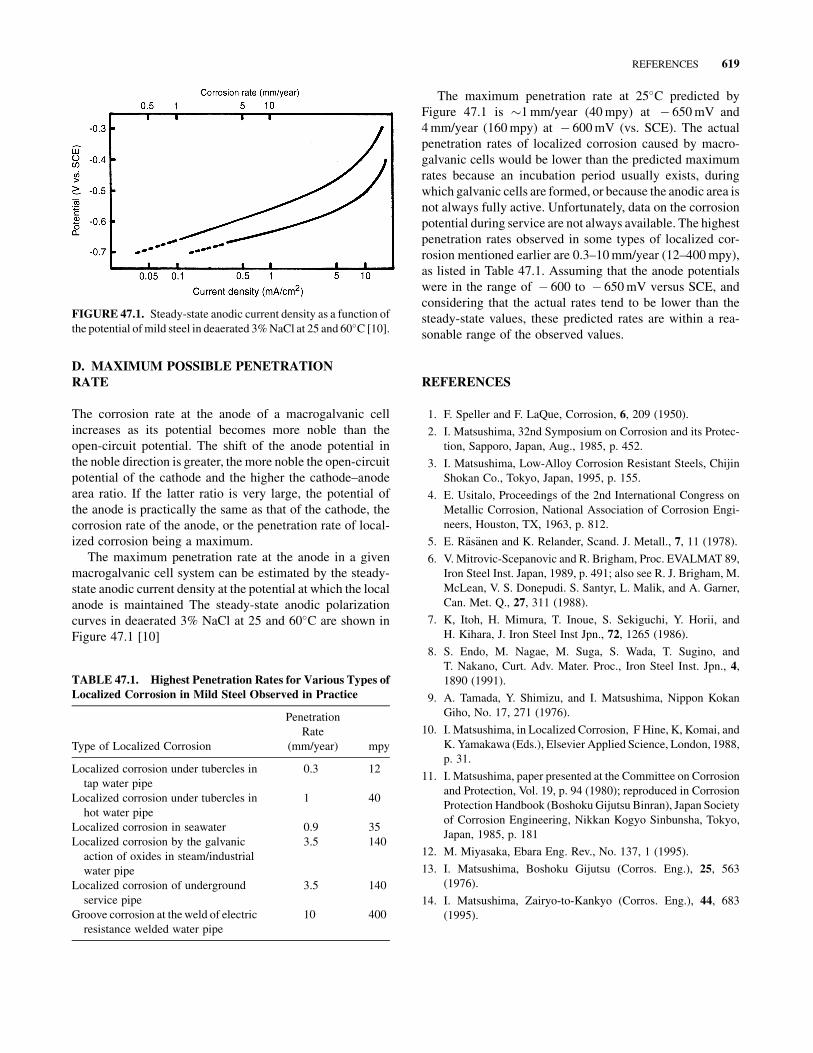
The maximum penetration rate at the anode in a given
macrogalvanic cell system can be estimated by the steady-
state anodic current density at the potential at which the local
anode is maintained The steady-state anodic polarization
curves in deaerated 3% NaCl at 25 and 60�C are shown in
Figure 47.1 [10]
The maximum penetration rate at 25�C predicted by
Figure 47.1 is �1mm/year (40mpy) at � 650mV and
4mm/year (160mpy) at � 600mV (vs. SCE). The actual
penetration rates of localized corrosion caused by macro-
galvanic cells would be lower than the predicted maximum
rates because an incubation period usually exists, during
which galvanic cells are formed, or because the anodic area is
not always fully active. Unfortunately, data on the corrosion
potential during service are not always available. The highest
penetration rates observed in some types of localized cor-
rosion mentioned earlier are 0.3–10mm/year (12–400mpy),
as listed in Table 47.1. Assuming that the anode potentials
were in the range of � 600 to � 650mV versus SCE, and
considering that the actual rates tend to be lower than the
steady-state values, these predicted rates are within a rea-
sonable range of the observed values.
REFERENCES
1. F. Speller and F. LaQue, Corrosion, 6, 209 (1950).
2. I. Matsushima, 32nd Symposium on Corrosion and its Protec-
tion, Sapporo, Japan, Aug., 1985, p. 452.
3. I. Matsushima, Low-Alloy Corrosion Resistant Steels, Chijin
Shokan Co., Tokyo, Japan, 1995, p. 155.
4. E. Usitalo, Proceedings of the 2nd International Congress on
Metallic Corrosion, National Association of Corrosion Engi-
neers, Houston, TX, 1963, p. 812.
5. E. R€as€anen and K. Relander, Scand. J. Metall., 7, 11 (1978).
6. V. Mitrovic-Scepanovic and R. Brigham, Proc. EVALMAT 89,
Iron Steel Inst. Japan, 1989, p. 491; also see R. J. Brigham, M.
McLean, V. S. Donepudi. S. Santyr, L. Malik, and A. Garner,
Can. Met. Q., 27, 311 (1988).
7. K, Itoh, H. Mimura, T. Inoue, S. Sekiguchi, Y. Horii, and
H. Kihara, J. Iron Steel Inst Jpn., 72, 1265 (1986).
8. S. Endo, M. Nagae, M. Suga, S. Wada, T. Sugino, and
T. Nakano, Curt. Adv. Mater. Proc., Iron Steel Inst. Jpn., 4,
1890 (1991).
9. A. Tamada, Y. Shimizu, and I. Matsushima, Nippon Kokan
Giho, No. 17, 271 (1976).
10. I. Matsushima, in Localized Corrosion, F Hine, K, Komai, and
K. Yamakawa (Eds.), Elsevier Applied Science, London, 1988,
p. 31.
11. I. Matsushima, paper presented at the Committee on Corrosion
and Protection, Vol. 19, p. 94 (1980); reproduced in Corrosion
Protection Handbook (BoshokuGijutsu Binran), Japan Society
of Corrosion Engineering, Nikkan Kogyo Sinbunsha, Tokyo,
Japan, 1985, p. 181
12. M. Miyasaka, Ebara Eng. Rev., No. 137, 1 (1995).
13. I. Matsushima, Boshoku Gijutsu (Corros. Eng.), 25, 563
(1976).
14. I. Matsushima, Zairyo-to-Kankyo (Corros. Eng.), 44, 683
(1995).
TABLE 47.1. Highest Penetration Rates for Various Types of
Localized Corrosion in Mild Steel Observed in Practice
Type of Localized Corrosion
Penetration
Rate
(mm/year) mpy
Localized corrosion under tubercles in
tap water pipe
0.3 12
Localized corrosion under tubercles in
hot water pipe
1 40
Localized corrosion in seawater 0.9 35
Localized corrosion by the galvanic
action of oxides in steam/industrial
water pipe
3.5 140
Localized corrosion of underground
service pipe
3.5 140
Groove corrosion at theweld of electric
resistance welded water pipe
10 400
FIGURE 47.1. Steady-state anodic current density as a function of
the potential ofmild steel in deaerated 3%NaCl at 25 and 60�C [10].
REFERENCES 619