ufc 3-210-01a area planning, site planning, and design
TRANSCRIPT

UFC 3-210-01A 16 January 2004
UNIFIED FACILITIES CRITERIA (UFC)
AREA PLANNING, SITE PLANNING,
AND DESIGN
APPROVED FOR PUBLIC RELEASE; DISTRIBUTION UNLIMITED

UFC 3-210-01A 16 January 2004
UNIFIED FACILITIES CRITERIA (UFC)
AREA PLANNING, SITE PLANNING, AND DESIGN
Any copyrighted material included in this UFC is identified at its point of use. Use of the copyrighted material apart from this UFC must have the permission of the copyright holder. U.S. ARMY CORPS OF ENGINEERS (Preparing Activity) NAVAL FACILITIES ENGINEERING COMMAND AIR FORCE CIVIL ENGINEER SUPPORT AGENCY Record of Changes (changes are indicated by \1\ ... /1/) Change No. Date Location
This UFC supersedes TI 804-01, dated 1 July 1998. The format of this UFC does not conform to UFC 1-300-01; however, the format will be adjusted to conform at the next revision. The body of this UFC is the existing TI 804-01, dated 1 July 1998.

UFC 3-210-01A 16 January 2004
FOREWORD \1\ The Unified Facilities Criteria (UFC) system is prescribed by MIL-STD 3007 and provides planning, design, construction, sustainment, restoration, and modernization criteria, and applies to the Military Departments, the Defense Agencies, and the DoD Field Activities in accordance with USD(AT&L) Memorandum dated 29 May 2002. UFC will be used for all DoD projects and work for other customers where appropriate. All construction outside of the United States is also governed by Status of forces Agreements (SOFA), Host Nation Funded Construction Agreements (HNFA), and in some instances, Bilateral Infrastructure Agreements (BIA.) Therefore, the acquisition team must ensure compliance with the more stringent of the UFC, the SOFA, the HNFA, and the BIA, as applicable. UFC are living documents and will be periodically reviewed, updated, and made available to users as part of the Services’ responsibility for providing technical criteria for military construction. Headquarters, U.S. Army Corps of Engineers (HQUSACE), Naval Facilities Engineering Command (NAVFAC), and Air Force Civil Engineer Support Agency (AFCESA) are responsible for administration of the UFC system. Defense agencies should contact the preparing service for document interpretation and improvements. Technical content of UFC is the responsibility of the cognizant DoD working group. Recommended changes with supporting rationale should be sent to the respective service proponent office by the following electronic form: Criteria Change Request (CCR). The form is also accessible from the Internet sites listed below. UFC are effective upon issuance and are distributed only in electronic media from the following source: • Whole Building Design Guide web site http://dod.wbdg.org/. Hard copies of UFC printed from electronic media should be checked against the current electronic version prior to use to ensure that they are current. AUTHORIZED BY: ______________________________________ DONALD L. BASHAM, P.E. Chief, Engineering and Construction U.S. Army Corps of Engineers
______________________________________DR. JAMES W WRIGHT, P.E. Chief Engineer Naval Facilities Engineering Command
______________________________________ KATHLEEN I. FERGUSON, P.E. The Deputy Civil Engineer DCS/Installations & Logistics Department of the Air Force
______________________________________Dr. GET W. MOY, P.E. Director, Installations Requirements and Management Office of the Deputy Under Secretary of Defense (Installations and Environment)

TI 804-011 July 1998
Technical Instructions
AREA PLANNING, SITE PLANNING, AND DESIGN
HeadquartersU.S. Army Corps of EngineersEngineering DivisionDirectorate of Military ProgramsWashington, DC 20314-1000

CEMP-ET TI 804-011 July 1998
TECHNICAL INSTRUCTIONS
AREA PLANNING, SITE PLANNING, AND DESIGN
Any copyrighted material included in this document is identified at its point of use.Use of the copyrighted material apart from this document must have the permission of the copyright holder.
Approved for public release; distribution is unlimited.
Record of Changes (changes indicated by \1\... /1/ )No. Date Page

CEMP-ET TI 804-011 July 1998
FOREWORD
These technical instructions (TI) provide design and construction criteria and apply to all U. S. ArmyCorps of Engineers (USACE) commands having military construction responsibilities. TI will be usedfor all Army projects and for projects executed for other military services or work for other customerswhere appropriate.
TI are living documents and will be periodically reviewed, updated, and made available to users aspart of the HQUSACE responsibility for technical criteria and policy for new military construction. CEMP-ET is responsible for administration of the TI system; technical content of TI is theresponsibility of the HQUSACE element of the discipline involved. Recommended changes to TI,with rationale for the changes, should be sent to HQUSACE, ATTN: CEMP-ET, 20 MassachusettsAve., NW, Washington, D.C. 20314-1000.
TI are effective upon issuance. TI are distributed only in electronic media through the TECHINFOInternet site http://www.hnd.usace.army.mil/techinfo/index.htm and the Construction Criteria Base(CCB) system maintained by the National Institute of Building Sciences at Internet sitehttp://www.nibs.org/ccb/. Hard copies of these instructions produced by the user from the electronicmedia should be checked against the current electronic version prior to use to assure that the latestinstructions are used.
FOR THE COMMANDER:
KISUK CHEUNG, P. E.Chief, Engineering and Construction DivisionDirector of Military Programs
CEMP-ET TI 804-011 July 1998
i
TECHNICAL INSTRUCTIONSAREA PLANNING, SITE PLANNING, AND DESIGN
Table of Contents
PageCHAPTER 1. INTRODUCTION
Paragraph 1-1. PURPOSE AND SCOPE . . . . . . . . . . . . . . . . . . . . . . . . . . . . . . . 1-1
1-2. APPLICABILITY . . . . . . . . . . . . . . . . . . . . . . . . . . . . . . . . . . . . . . 1-1
1-3. REFERENCES . . . . . . . . . . . . . . . . . . . . . . . . . . . . . . . . . . . . . . 1-1
1-4. DESIGN TEAM . . . . . . . . . . . . . . . . . . . . . . . . . . . . . . . . . . . . . . 1-1
CHAPTER 2. REQUIREMENTS
Paragraph 2-1. GENERAL . . . . . . . . . . . . . . . . . . . . . . . . . . . . . . . . . . . . . . . . . . 2-1
2-2. PURPOSE . . . . . . . . . . . . . . . . . . . . . . . . . . . . . . . . . . . . . . . . . . 2-1
2- 3. THE AREA DEVELOPMENT PLAN PROCESS . . . . . . . . . . . . . 2-1
CHAPTER 3. THE SITE PLAN
Paragraph 3-1. GENERAL . . . . . . . . . . . . . . . . . . . . . . . . . . . . . . . . . . . . . . . . . . 3-1
3-2. RELATIONSHIP TO THE AREA DEVELOPMENT PLAN . . . . . . 3-1
3-3. THE SITE PLANNING PROCESS . . . . . . . . . . . . . . . . . . . . . . . 3-1
CHAPTER 4. DESIGN CRITERIA
Paragraph 4-1. GENERAL . . . . . . . . . . . . . . . . . . . . . . . . . . . . . . . . . . . . . . . . . . 4-1
4-2. BUILDING DESIGN, LOCATION, AND ORIENTATION . . . . . . . 4-1
4-3. VEHICULAR CIRCULATION AND PARKING . . . . . . . . . . . . . . . 4-3

CEMP-ET TI 804-011 July 1998
ii
Table of Contents (continued)
Page
Paragraph 4-4. PEDESTRIAN CIRCULATION . . . . . . . . . . . . . . . . . . . . . . . . . . . . . . . . 4-6
4-5. SURFACE WATER MANAGEMENT . . . . . . . . . . . . . . . . . . . . . . . . . . 4-10
4-6. UTILITY SYSTEMS DESIGN . . . . . . . . . . . . . . . . . . . . . . . . . . . . . . . . 4-11
4-7. LIGHTING DESIGN . . . . . . . . . . . . . . . . . . . . . . . . . . . . . . . . . . . . . . . 4-11
4-8. LANDSCAPE DESIGN . . . . . . . . . . . . . . . . . . . . . . . . . . . . . . . . . . . . . 4-11
4-9. PHYSICAL SECURITY . . . . . . . . . . . . . . . . . . . . . . . . . . . . . . . . . . . . 4-11
APPENDIX A REFERENCES . . . . . . . . . . . . . . . . . . . . . . . . . . . . . . . . . . . . . . . . . . . A-1
FIGURES
Figure Title
1-1 Planning hierarchy . . . . . . . . . . . . . . . . . . . . . . . . . . . . . . . . . . . . . . . . . . . . . . . . . . 1-3
2-1 The area development plan process . . . . . . . . . . . . . . . . . . . . . . . . . . . . . . . . . . . 2-18
2-2 Functional relationships bubble diagram . . . . . . . . . . . . . . . . . . . . . . . . . . . . . . . . 2-19
2-3 Functional relationships matrix . . . . . . . . . . . . . . . . . . . . . . . . . . . . . . . . . . . . . . . . 2-19
2-4 Area land use . . . . . . . . . . . . . . . . . . . . . . . . . . . . . . . . . . . . . . . . . . . . . . . . . . . . 2-20
2-5 Area Transportation . . . . . . . . . . . . . . . . . . . . . . . . . . . . . . . . . . . . . . . . . . . . . . . . 2-20
2-6 Area utility supply lines . . . . . . . . . . . . . . . . . . . . . . . . . . . . . . . . . . . . . . . . . . . . . . 2-21
2-7 Analysis of natural environment . . . . . . . . . . . . . . . . . . . . . . . . . . . . . . . . . . . . . . . 2-22
2-8 Analysis of built environment . . . . . . . . . . . . . . . . . . . . . . . . . . . . . . . . . . . . . . . . . 2-22
2-9 Analysis of socio-cultural environment . . . . . . . . . . . . . . . . . . . . . . . . . . . . . . . . . . 2-23
2-10 Opportunities and constraints . . . . . . . . . . . . . . . . . . . . . . . . . . . . . . . . . . . . . . . . . 2-23
2-11 Alternative 1 sketch plan . . . . . . . . . . . . . . . . . . . . . . . . . . . . . . . . . . . . . . . . . . . . 2-24

CEMP-ET TI 804-011 July 1998
iii
Table of Contents (continued)
Page
2-12 Alternative 2 sketch plan . . . . . . . . . . . . . . . . . . . . . . . . . . . . . . . . . . . . . . . . . . . . 2-24
2-13 Alternative 3 sketch plan . . . . . . . . . . . . . . . . . . . . . . . . . . . . . . . . . . . . . . . . . . . 2-25
2-14 Evaluation matrix . . . . . . . . . . . . . . . . . . . . . . . . . . . . . . . . . . . . . . . . . . . . . . . . . . 2-25
2-15 Preliminary area development plan . . . . . . . . . . . . . . . . . . . . . . . . . . . . . . . . . . . . 2-26
2-16 Location map . . . . . . . . . . . . . . . . . . . . . . . . . . . . . . . . . . . . . . . . . . . . . . . . . . . . 2-26 2-17 Final area development plan . . . . . . . . . . . . . . . . . . . . . . . . . . . . . . . . . . . . . . . . . 2-27
2-18 Phasing Plan . . . . . . . . . . . . . . . . . . . . . . . . . . . . . . . . . . . . . . . . . . . . . . . . . . . . . 2-28
3-1 Analysis of natural environment . . . . . . . . . . . . . . . . . . . . . . . . . . . . . . . . . . . . . . . 3-10
3-2 Site opportunities and constraints . . . . . . . . . . . . . . . . . . . . . . . . . . . . . . . . . . . . . . 3-11
3-3 Alternative 1 . . . . . . . . . . . . . . . . . . . . . . . . . . . . . . . . . . . . . . . . . . . . . . . . . . . . . . 3-12
3-4 Alternative 2 . . . . . . . . . . . . . . . . . . . . . . . . . . . . . . . . . . . . . . . . . . . . . . . . . . . . . . 3-12
3-5 Alternative 3 . . . . . . . . . . . . . . . . . . . . . . . . . . . . . . . . . . . . . . . . . . . . . . . . . . . . . . 3-13
3-6 Site evaluation matrix . . . . . . . . . . . . . . . . . . . . . . . . . . . . . . . . . . . . . . . . . . . . . . . 3-13
3-7 Preliminary site plan . . . . . . . . . . . . . . . . . . . . . . . . . . . . . . . . . . . . . . . . . . . . . . . . 3-14
3-8 Final site plan . . . . . . . . . . . . . . . . . . . . . . . . . . . . . . . . . . . . . . . . . . . . . . . . . . . . . 3-14
4-1 Dimensional factors . . . . . . . . . . . . . . . . . . . . . . . . . . . . . . . . . . . . . . . . . . . . . . . . 4-13
4-2 Solar orientation . . . . . . . . . . . . . . . . . . . . . . . . . . . . . . . . . . . . . . . . . . . . . . . . . . . 4-14
4-3 Slope orientation . . . . . . . . . . . . . . . . . . . . . . . . . . . . . . . . . . . . . . . . . . . . . . . . . . . 4-15
4-4 Wind orientation . . . . . . . . . . . . . . . . . . . . . . . . . . . . . . . . . . . . . . . . . . . . . . . . . . . 4-15
4-5 Visual factors . . . . . . . . . . . . . . . . . . . . . . . . . . . . . . . . . . . . . . . . . . . . . . . . . . . . . 4-16
4-6 Vehicular circulation . . . . . . . . . . . . . . . . . . . . . . . . . . . . . . . . . . . . . . . . . . . . . . . . 4-17
4-7 Parking . . . . . . . . . . . . . . . . . . . . . . . . . . . . . . . . . . . . . . . . . . . . . . . . . . . . . . . . . . 4-17
CEMP-ET TI 804-011 July 1998
iv
Table of Contents (continued)
Page
4-8 Dumpster location . . . . . . . . . . . . . . . . . . . . . . . . . . . . . . . . . . . . . . . . . . . . . . . . . . 4-18
4-9 Pedestrian circulation patterns . . . . . . . . . . . . . . . . . . . . . . . . . . . . . . . . . . . . . . . . 4-18
4-10 Sidewalk plans . . . . . . . . . . . . . . . . . . . . . . . . . . . . . . . . . . . . . . . . . . . . . . . . . . . . 4-19
4-11 Minimize grading . . . . . . . . . . . . . . . . . . . . . . . . . . . . . . . . . . . . . . . . . . . . . . . . . . . 4-20
4-12 Surface water management . . . . . . . . . . . . . . . . . . . . . . . . . . . . . . . . . . . . . . . . . . 4-20
4-13 Detention, retention, and infiltration principles . . . . . . . . . . . . . . . . . . . . . . . . . . . . 4-21
4-14 Erosion control . . . . . . . . . . . . . . . . . . . . . . . . . . . . . . . . . . . . . . . . . . . . . . . . . . . . 4-22

CEMP-ET TI 804-011 July 1998
1-1
CHAPTER 1
INTRODUCTION
1-1. PURPOSE AND SCOPE. These Technical Instructions (TI) describe the AreaDevelopment Planning (ADP) and Site Planning processes to be used in preparing plans forconstruction drawings. The instructions are intended to be used by those individuals given theresponsibility for site planning which includes site selection, site development, and site design.The planning procedures that occur in developing a project are described in these instructions.The procedures described are sound and provide a logical process to the end result.
a. Area Development Plan. The ADP is described as providing facility planning at thesmall area or sub-area level which falls between master planning for an entire installation(RPMP) and site planning for individual buildings (see figure 1-1). The ADP process includesthe phases--Identification, Evaluation and Implementation. Identification includes defining thegoals and objectives, verifying the program requirements, developing functional relationships,defining spatial relationships, providing an inventory of the area and accomplishing a site visit. Evaluation includes the development of a site analysis that graphically shows thedevelopmental opportunities and constraints for the area. Alternative conceptual plans aredeveloped for evaluation and a determination of a final area development plan isaccomplished. Implementation includes the procedures of the Army military constructionprogram for development and execution.
b. Site Plan. Site planning is described as further defining the functional layout forspecific buildings or functions and their site. It also includes the phases--Identification,Evaluation, and Implementation. Identification includes defining site specific goals andobjectives, verifying the program requirements, developing functional relationships, definingspatial relationships, providing an inventory of the area and accomplishing a site visit. Evaluation includes the development of a site analysis that graphically shows thedevelopmental opportunities and constraints for the site. Alternative conceptual plans aredeveloped for evaluation and a determination of a final site plan is accomplished. The resultingsite plan provides the basis for the preparation of construction drawings. Implementationincludes the procedures of the Army military construction program for development andexecution. The design criteria discusses building design, location and orientation, vehicularcirculation and parking, pedestrian circulation, surface water management, utility systemsdesign, lighting design, landscape design, and physical security.
1-2. APPLICABILITY. These instructions are applicable to all USACE elements involved inpreparing plans for areas, sites, and facilities for Army and civilian installations.
1-3. REFERENCES. References used in these instructions are identified in appendix A.
1-4. DESIGN TEAM. The ADP and site planning processes should be the responsibility of aninterdisciplinary team of design professionals (see ER 1110-1-8152, ProfessionalRegistration). This multi-professional approach to the planning process helps assure that allaspects of the man-made and natural characteristics of the area being planned are properlyand thoroughly considered (see ER 1110-1-12, Engineering and Design Quality Management). Plans are prepared to provide a comprehensive solution to the program requirementsaddressing environmental assessment of actions, design quality, and economic efficiency.

CEMP-ET TI 804-011 July 1998
1-2
The interdisciplinary team should be identified at the beginning of the planning process so thatits expertise can be applied from the outset. The membership of the team and the team leaderwill be determined by the functional requirements of the project. There are typically four majorcomponents of a planning and design team: landscape architecture, land planning, civilengineering, and architecture. The landscape architect may take the lead role because of theexpertise required in area and site planning. Other professionals such as mechanical andelectrical engineers, hydrologists, geologists, and historic preservationists may be included inthe planning process as warranted by specific conditions. Intended users and other citizensshould also be involved throughout the process. User input is critical to the success of theplan.

CEMP-ET TI 804-011 July 1998
1-3
Installation scale
Vicinity scale
Area scaleSite scale
Figure 1-1. Planning Hierarchy

CEMP-ET TI 804-011 July 1998
2-1
CHAPTER 2
THE AREA DEVELOPMENT PLAN
2-1. GENERAL. This chapter provides guidance for the preparation of an Area DevelopmentPlan (ADP). The ADP is a process used to prepare a planning framework for areas that consistof complex or incompatible functions or functions requiring large areas of land which impactcirculation and utilities. It may include a number of individual buildings or activities withcommon elements associated by function such as administration facilities or barracks facilities,or facilities that differ in use but are associated by proximity.
2-2. PURPOSE. The ADP provides for the definition of program requirements by coordinatingthe location of buildings, vehicular and pedestrian access, parking, open space and otheractivities or facilities within the area. The end result of the process is a plan for the area bothin written and graphic format. It describes the planning process, presents an efficient,economic and functional plan and provides direction for implementing the plan. Graphics are ofprimary importance throughout the plan to communicate the design intent and planningprinciples that are proposed for the area. The Final Area Plan is a graphic illustration of all ofthe elements proposed to occur within the area boundaries. The plan also includes details orsketches to illustrate important land use, circulation, and utilities. The plans, text, and graphicsprovide a framework that defines an efficient, economic, and functional area. The actualconfiguration of the individual sites can then be further refined in the Site Planning processdescribed in chapter 3. The area development process uses urban design principles tointegrate incompatible land uses and functional requirements within the existing manmade andnatural environment.
2-3. THE AREA DEVELOPMENT PLAN PROCESS. The ADP process is designed to occur ina series of steps or actions that result in a Final Area Development Plan. The process isillustrated by the flow chart in figure 2-1. The process involves standard land use planningpractices in three major planning phases: Identification, Evaluation, and Implementation. Theprocess is sequential and designed to be followed from beginning to end. Area boundariesand general decisions as to how and by whom the area will be used should have been definedin the Real Property Master Plan. If not, the selection of area boundaries will be determinedbefore the ADP process can begin. For this document, an Area Development Plan for aCommunity Center will be developed to illustrate the sequence of steps included in theprocess.
a. Identification. The identification phase includes the setting of goals and objectives,defining facility and spatial requirements, defining functional relationships, and the collection ofbase maps and data.
(1) Goals and Objectives. The first step in the area development plan process is todefine project goals and objectives and installation development goals. Goals and objectivesfor the project are derived from the user mission. The user mission should be reviewedcarefully to determine how the proposed project is intended to accomplish or support themission.

CEMP-ET TI 804-011 July 1998
2-2
(a) The user's specific needs will be determined for the following:
1/ Functional requirements
2/ Creation of organizational efficiency and safety
3/ Relationship to adjacent functions
4/ Contribution to the quality of life of the occupants
(b) The project goals and objectives become guidelines for the planningprocess. Goals are general, while objectives define specific actions to achieve the goals. Thefollowing goals and objectives are representative of what might be developed for anInstallation Community Center ADP. They are based upon the installation goals as stated inthe Real Property Master Plan:
1/ Goal: Plan an Installation Community Center that maximizes functionalrelationships between uses and the interior and exterior spaces.
a/ Objective 1: Locate buildings and parking to provide for ease of accessand minimal walking distances.
b/ Objective 2: Provide for centrally located exterior space, away from traffic, that will serve as a meeting area for informal gatherings and lunch-time activity.
c/ Objective 3: Provide for pedestrian access, protected from the weather,that links the various buildings, exterior spaces and parking.
2/ Goal: Provide for direct, safe and easy vehicular and pedestrian accessto the Installation Community Center.
a/ Objective 1: Provide most direct access from the Main Gate and from allparts of the installation via collector streets.
b/ Objective 2: Minimize conflicts of vehicular traffic and pedestrian accessin parking lots.
c/ Objective 3: Provide for separation of customer traffic and deliverytraffic.
(2) Facility and Land Area Requirements. Once the goals and objectives have beenadopted, the development requirements and the spatial needs of these requirements can beidentified. Accurate project requirements are fundamental to organizing and locating projectelements on site. Failure to anticipate true programmatic and spatial needs can createincompatible land use and inefficient spatial arrangements, especially on small or confinedsites. The land area or spatial requirements are determined by the size of the various facilitiesand other activities to be included within the area to serve the facilities such as driveways,walkways, parking and open space. Functional requirements are based upon the number of

CEMP-ET TI 804-011 July 1998
2-3
employees to be housed within the facility. As an example, The following list defines theactivities to be included in the Community Center ADP.
(a) Commissary.
(b) Guest housing.
(c) Credit union.
(d) Bank.
(e) Convenient parking for new facilities.
(f) Safe, convenient vehicular circulation.
(g) Open space for separation of activities.
(h) Open space for future development.
(i) Safe, convenient, direct access for service vehicles.
(j) Separate pedestrian and vehicular circulation.
(k) Protect environmentally sensitive areas.
(3) Functional Relationships. The functional relationships of the proposed facilitiesmust be defined so that they can be organized within the plan. This process consists ofanalyzing the interactions between facilities and activities to determine whether a given pairneed to be linked or separated in order to function properly and be compatible.
(a) Functional Relationship Diagrams. The desired functional relationships aredefined graphically through the use of Functional Relationships Diagrams. These diagramsorganize facilities into ideal arrangements, based upon their interdependence. The diagramdelineates the best locations for facilities in relation to each other, irrespective of siteconsiderations. These diagrams can be developed as matrices or as “bubble diagrams”. Thetwo types of functional relationships diagrams are illustrated in figures 2-2 and 2-3 and furtherdefined as follows:
1/ Bubble Diagrams are drawn to scale to define the size of the variousactivities as well as their interrelationships. In a bubble diagram, each bubble is connectedwith lines which illustrate the importance of the relationship to each other and whetherconnection or separation is appropriate. The bubble diagram approach is recommendedbecause it provides a visual analysis of the desired relationships. The result of the bubblediagrams is a spatial relationship of the functional requirements. This relationship determinesif the program requirements fit on the selected site. A bubble diagram may be developedthrough the following steps:
a/ Delineate the approximate size of the primary facility in a bubble or block.

CEMP-ET TI 804-011 July 1998
2-4
b/ Delineate the approximate size of support facilities into bubbles or blocks.
c/ Arrange the bubbles or blocks of primary and support facilities for optimalsupport.
d/ Delineate necessary connection and separation between facilities usingweighted lines.
e/ Delineate major vehicular access and circulation with weighted lines witharrows to indicate access points and direction of traffic flow.
f/ Delineate major pedestrian access and circulation using weighted linesand arrows.
g/ Delineate future facilities and circulation using dashed lines.
2/ A matrix compares facilities or activities numerically or symbolically.
(4) Base Map and Data Collection. The inventory of area data will typically occursimultaneously with the analysis of project requirements and functional relationships. Thisinventory includes the collection of base maps and data about the environmental andmanmade characteristics of the area and its environs. Existing maps and other data should beused whenever possible to prevent duplication of information. The data to be collected shouldinclude the following:
(a) Base Maps. The base maps to be used for preparing ADP maps and planswill typically be prepared at a ratio of 1:2000. These scales may vary depending upon the sizeof the area or degree of detail being provided. The following will be collected or prepared:
1/ Area Base Map. The Area Base Map provides specific data about the areaand will be used as a base sheet upon which subsequent maps will be developed. Informationtypically provided on an Area Base Map includes existing structures; roadways, driveways,parking and walkways, topography, streams, water bodies, vegetation, fence lines, location ofutilities, and other significant information. The map will be drawn to scale and will show a northarrow.
2/ Vicinity Map. The Vicinity Map includes the area development boundaryand the surrounding areas. Coverage and detail in this map will vary depending upon the sizeand complexity of the area. The Vicinity Map includes much of the same information as theSite Base Map, but is prepared at a smaller scale to include more area. It is also drawn toscale and showing a north arrow.
3/ Location Map. The Location Map shows the location of the areadevelopment in a regional context. The map should be drawn at a very small scale to showthe relationship of the site to the region. Typically, this would include the installationboundaries and major roadways within the installation and outside the installation, and majornatural features such as an ocean, river or mountain range.
CEMP-ET TI 804-011 July 1998
2-5
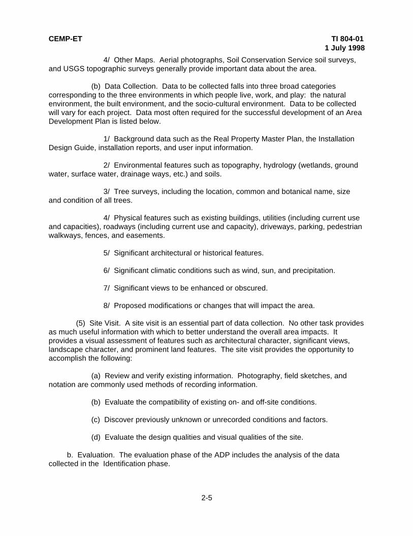
4/ Other Maps. Aerial photographs, Soil Conservation Service soil surveys,and USGS topographic surveys generally provide important data about the area.
(b) Data Collection. Data to be collected falls into three broad categoriescorresponding to the three environments in which people live, work, and play: the naturalenvironment, the built environment, and the socio-cultural environment. Data to be collectedwill vary for each project. Data most often required for the successful development of an AreaDevelopment Plan is listed below.
1/ Background data such as the Real Property Master Plan, the InstallationDesign Guide, installation reports, and user input information.
2/ Environmental features such as topography, hydrology (wetlands, groundwater, surface water, drainage ways, etc.) and soils.
3/ Tree surveys, including the location, common and botanical name, sizeand condition of all trees.
4/ Physical features such as existing buildings, utilities (including current useand capacities), roadways (including current use and capacity), driveways, parking, pedestrianwalkways, fences, and easements.
5/ Significant architectural or historical features.
6/ Significant climatic conditions such as wind, sun, and precipitation.
7/ Significant views to be enhanced or obscured.
8/ Proposed modifications or changes that will impact the area.
(5) Site Visit. A site visit is an essential part of data collection. No other task providesas much useful information with which to better understand the overall area impacts. Itprovides a visual assessment of features such as architectural character, significant views,landscape character, and prominent land features. The site visit provides the opportunity to accomplish the following:
(a) Review and verify existing information. Photography, field sketches, andnotation are commonly used methods of recording information.
(b) Evaluate the compatibility of existing on- and off-site conditions.
(c) Discover previously unknown or unrecorded conditions and factors.
(d) Evaluate the design qualities and visual qualities of the site.
b. Evaluation. The evaluation phase of the ADP includes the analysis of the datacollected in the Identification phase.

CEMP-ET TI 804-011 July 1998
2-6
(1) ADP Site Analysis. The area site analysis includes verifying and recordingcollected data in a series of maps, charts and text that document all existing conditions, bothwithin and outside the area. This information provides a basis for the evaluation of the impactsthat the existing conditions will have on-site development. All collected data and analysisresults should be well documented. The analysis will be accomplished by overlaying thetopographic map with transparencies of soils, hydrology and vegetation maps to define thenatural conditions of the site. All manmade elements such as buildings, roadways, and utilitylines should be overlaid on the natural conditions. This series of maps define the developmentpotential of the area. During the analysis, it is important to understand the impacts variouselements can have on the area. It is also important to know how these elements interrelateand are impacted by one another. The following elements should be evaluated:
(a) Off-Site Conditions. An area development is influenced by factors adjacentto the site. Both existing conditions and future development should be considered. Thefollowing elements should be evaluated for potential impacts and especially potentialconnections with the area development.
1/ Land Use. Surrounding land use should be recorded and the land usecategory verified (see figure 2-4).
2/ Transportation. All existing and proposed vehicular transportationsystems to and around the area should be located and evaluated for their hierarchy andcurrent operating capacity. Primary and secondary roadways should be examined todetermine access points, traffic loads and vehicular safety requirements. All parking areasshould be recorded. Bus routes and loading zones should be identified (see figure 2-5). ASite Traffic Impact Analysis for the area may be prepared.
3/ Utilities. All primary utilities and utility lines should be located and the sizeof the lines, capacities of generation, and current and projected utilization identified (see figure2-6). The utilities include:
a/ Water system with locations of fire hydrants.
b/ Sanitary sewer system.
c/ Storm drainage system and drainage basin with invert elevations.
d/ Electrical, gas, and steam systems.
e/ Telephone system.
f/ Other types of communication systems or specialized utility systems.
4/ Environmental Conditions and Hazards. All areas or conditions ofenvironmental concern near the area should be recorded. AR 200-2 and AR 415-15 providefurther guidance on assessing environmental conditions.

CEMP-ET TI 804-011 July 1998
2-7
a/ Storm drainage patterns indicating watershed boundaries and thedirection of flow.
b/ Storm water management areas.
c/ Flood plain.
d/ Wetland areas.
e/ Wildlife habitats (especially for threatened and endangered species).
f/ Buried tanks, Installation Restoration Program (IRP).
g/ Other hazards.
5/ Historic, Cultural and/or Archeological Resources. All structures or sitesthat have been defined as historically, culturally or archeologically significant in the vicinity ofthe area should be identified.
6/ Safety Hazards. All requirements and distances necessary for safetysuch as fire codes, flood control, airfield and helipad clear zones, and explosives safety shouldbe identified.
7/ Physical Security. Coordinate the physical security requirements with the Physical Security Plan of the installation. Existing or potential threat, high risk targets, andcurrent vulnerabilities to deter attack should be determined by consulting the Provost Marshal.
8/ Sources of Air, Noise and Light Pollution. Immediate or point sources ofpollution should be identified and their impact upon the site evaluated. Information may befound in the environmental impact assessments for the installation. The need and potential forachieving mitigation should be indicated. Non-point sources of pollution entering or leaving thearea development should also be evaluated.
9/ Visual Enclosure. The area's viewshed (area of visual enclosure) extendsbeyond the area boundaries. The degree to which the surrounding environment contributes tothe area's sense of enclosure or openness, may create desirable or undesirable views fromthe area. There may need to be buffers for the area's own visual condition.
(b) On-Site Conditions. All factors within the area boundary should be recorded. Both existing conditions and future development should be considered. Each factor isanalyzed and recorded as part of the Natural Environment Analysis (figure 2-7), the BuiltEnvironment Analysis (figure 2-8), or the Socio-cultural Environment Analysis (figure 2-9). Thefollowing elements should be examined to evaluate potential impacts and connections withinthe area development.
1/ Geology. Geological conditions above and below the ground surfaceshould be evaluated for the type of rock and its geologic formation.

CEMP-ET TI 804-011 July 1998
2-8
2/ Topography. Existing elevations, high points, low points, and slopesshould be defined. Slopes are usually described by their percent grade and placed inappropriate ranges (e.g., 0-5%, 5-10%, 10-20%, etc.).
3/ Hydrology. A hydrologic assessment provides information on surface andsubsurface water movement. This information can be used to prevent flooding, erosion, andpollution of surface and groundwater and to promote groundwater recharge, habitatdevelopment, and recreational use.
a/ Subsurface. Subsurface hydrology concerns the storage and movementof water beneath the soil surface. Groundwater moves through the soil and through aquifers. Because aquifers are potential sources of potable water, federal, state and local agencies mayregulate the quantity and quality of water allowed to infiltrate the ground surface. If a site is ina groundwater recharge area, there may be restrictions upon the amount of impermeablesurface to be implemented and upon the water quality allowed for infiltration.
b/ Surface. Existing surface water bodies such as rivers, lakes, ponds,streams and springs should be recorded. Drainage patterns, flood plains, impermeablesurfaces (pavements and rooftops) and other conditions affecting the movement of surfacewater should also be recorded. Significant information should be depicted graphically.
4/ Soils. Soils types and locations should be recorded and depictedgraphically. The development potential of each type should be defined.
5/ Climate. A complete climatic evaluation of the site should be defined. Climatic conditions affect such planning concerns as building location and orientation,pedestrian circulation, and vegetation. The following information should be obtained andevaluated:
a/ Average monthly temperature range.
b/ Quantity, frequency, and type of precipitation.
c/ Midwinter and midsummer sunrise and sunset orientation and angle.
d/ Prevailing wind direction throughout the year.
6/ Vegetation. The location of all existing trees should be showngraphically. The trees should be located by survey and identified by common and botanicalname, size and condition. Identification of local plant associations provide information on thetypes of tree and understory plant material which thrive in the area and should be used forlandscape design applications when the area is developed.
7/ Wildlife Habitat. Natural wildlife habitats within the development areashould be identified. Threatened and endangered species habitat requires protection.
8/ Archeological, Cultural and Historic Resources. Structures or sites thathave been defined as historically, culturally or archeologically significant should be identified.

CEMP-ET TI 804-011 July 1998
2-9
Those requiring preservation will have a significant impact on the development potential of thearea.
9/ Visual Survey. An evaluation of the visual character of the area. Thisevaluation is made during the site visit and attempts to capture the feeling or essence of thearea. Aspects of the assessment including the following:
a/ General geologic, topographic and vegetative character.
b/ Visual character of the site including view boundaries, good and poorsite-specific views and their potential for enhancement or mitigation, and special visualfeatures which define the character of the site or make a strong visual impact. Examplesinclude: water bodies, mature tree specimens, rock outcrops, and sunlight and shadow.
c/ Sensory information such as odor, noise, or open or confined spaces.
d/ Microclimate conditions, such as warm or cold areas.
(2) Opportunities and Constraints. The evaluations made in the area site analysisare recorded on a map that summarizes the opportunities and constraints for development(figure 2-10). The opportunities and constraints evaluation is used to verify the adequacy ofthe area for the proposed project.
(a) The opportunities and constraints map interprets area features as eitheropportunities to be explored and enhanced or constraints to be avoided or mitigated. Opportunities and constraints maps should define the following:
1/ Natural features to be preserved for environmental protection.
2/ Natural features to be conserved.
3/ Natural features that affect construction (poor soils, steep slopes, etc.).
4/ Climatic impacts of temperature, solar radiation, wind, and precipitation.
5/ Existing structures or other landmarks to be preserved or enhancedbecause of historic, architectural, or other significance.
6/ Existing structures or other landmarks that share functionalrelationships and connections with the future development.
7/ Existing structures or other features that have a negative impact on thearea through poor siting, visual intrusion, deteriorated condition, noise, or some other factor.
8/ Vehicular or pedestrian circulation points of conflict and opportunity
9/ All utilities to serve the area or that will impact development.
CEMP-ET TI 804-011 July 1998
2-10
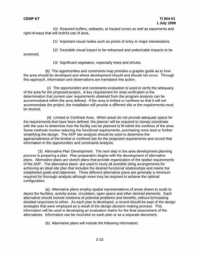
10/ Required buffers, setbacks, or hazard zones as well as easements andright-of-ways that will restrict use of area.
11/ Important visual nodes such as points of entry or major intersections.
12/ Desirable visual impact to be enhanced and undesirable impacts to bescreened.
13/ Significant vegetation, especially trees and shrubs.
(b) The opportunities and constraints map provides a graphic guide as to howthe area should be developed and where development should and should not occur. Throughthis approach, information and observations are translated into action.
(c) The opportunities and constraints evaluation is used to verify the adequacyof the area for the proposed project. A key requirement for area verification is thedetermination that current user requirements obtained from the program analysis can beaccommodated within the area defined. If the area is limited or confined so that it will notaccommodate the project, the installation will provide a different site or the requirements mustbe revised.
(d) Limited or Confined Area. When areas do not provide adequate space forthe requirements that have been defined, the planner will be required to closely coordinatewith the user to determine how the facility can be planned to fit within the confines of the area. Some methods involve reducing the functional requirements, purchasing more land or furthersimplifying the design. The ADP site analysis should be used to determine theappropriateness of the limited or confined site for the proposed requirements and record thatinformation in the opportunities and constraints analysis.
(3) Alternative Plan Development. The next step in the area development planningprocess is preparing a plan. Plan preparation begins with the development of alternativeplans. Alternative plans are sketch plans that provide organization of the spatial requirementsof the ADP. The alternative plans are used to study all possible siting arrangements forachieving an ideal site plan that includes the desired functional relationships and meets theestablished goals and objectives. Three different alternative plans are generally a minimumrequired for thorough analysis although more may be required to achieve the optimalconfiguration.
(a) Alternative plans employ spatial representations of areas drawn to scale todepict the facilities, activity areas, circulation, open space and other desired elements. Eachalternative should include notations of potential problems and benefits, without formulatingdetailed responses to either. As each plan is developed, a record should be kept of the designstrategies that were employed as a result of the design decision making process. Thisinformation will be used in developing an evaluation matrix for the final assessment of thealternatives. Information can be recorded on each plan or as a separate document.
(b) Alternative plans will include the following information:

CEMP-ET TI 804-011 July 1998
2-11
1/ Delineation of area boundary.
2/ Vehicular circulation throughout the area.
3/ Delineation of existing and proposed development sites.
4/ Site access points, including service access.
5/ Pedestrian access and potential linkage.
6/ Significant features and proposed landmarks.
(c) The Army provides standard designs for many facilities which may include asite plan to be used where applicable. The standard designs serve as guides only and do notrefer to any individual area.
(d) The preparation and evaluation of three alternative plans for the installationcommunity center are provided below as examples of the alternative plan preparation andreview procedure process discussed.
1/ Alternative 1 (figure 2-11) includes the following:
a/ Spatial requirements for parking have been provided for all new facilitieslocated within the area.
b/ The guest housing facility has been located near the entrance to theinstallation to accommodate visitors easily.
c/ The environmentally sensitive area located at the north end of the areahas been preserved and used for passive recreation. Pedestrian access is provided from thecommercial center to encourage environmental interaction.
d/ Vehicular circulation has been modified. Existing roadways have beenpreserved wherever feasible. A traffic circle has been developed at the center of the area. This element will serve as a hub around which traffic will flow without having to stop. Alandmark or monument is proposed for the center of the traffic circle to serve as a visual focalpoint. This design facilitates the addition of a fifth roadway to provide access to the bank andguest housing facilities. The entrance roadway has been extended to provide through accessto the southeast area of the installation.
e/ Ample open space has been preserved, especially in response to thetraffic circle. The proposed open space serves as a visual buffer between elements and toemphasize the central landmark. A large parcel of land at the south end of the area has beenpreserved for future development.
f/ The credit union facility has been located at the southern end of the areaat the intersection of the entrance road and the south connector road. This location will

CEMP-ET TI 804-011 July 1998
2-12
facilitate ease of use and is convenient to users who do not wish to enter the communitycenter.
g/ The bank facility is located in the northwest corner near the entrance tothe installation to provide convenient access from on-base and off-base.
h/ Service vehicles must circulate through the main traffic circle to reach theservice entrances of the commercial center site. This may create some traffic congestionthrough the hub, but results in the preservation of the environmentally sensitive area.
i/ Pedestrian access has been provided throughout the area. In areas ofhigh use, pedestrian access has been separated from vehicular access. Separate pedestrianaccess has been provided between the commercial center and the bank and between thecommercial center and the recreation area as well as within the commercial center.
j/ The commissary facility has been sited adjacent to the PX at the northend of the site in an effort to consolidate the facilities and resources.
2/ Alternative 2 (figure 2-12) includes the following:
a/ Spatial requirements for parking has been provided for all new facilitieslocated within the area.
b/ The guest housing facility has been located near the entrance to theinstallation to accommodate visitors easily.
c/ The environmentally sensitive area located at the north end of the areahas been preserved and used for passive recreation. Pedestrian access is provided from thecommercial center and from the guest housing facility to encourage environmental interaction.
d/ Vehicular circulation has been modified. Existing roadways have beenpreserved wherever feasible. Traffic circles have been created at the two busiestintersections. A landmark has been proposed for the center of each of these intersections. Inaddition, a north-south connecting roadway has been created to improve access to thecommercial center. The entrance roadway has been extended to provide through access tothe southeast area of the installation.
e/ Open space has been preserved at the entrance to the installation andalong the entrance roadway. These two spaces provide a buffer for the guest housing facility. A large parcel centrally located within the area has been preserved for future development.
f/ The credit union facility has been located at the southeastern corner ofthe area. This location will facilitate ease of use and is convenient to users who do not wish toenter the community center. The credit union has been located adjacent to the bank facility toconsolidate land uses and improve vehicular circulation.
g/ The bank facility is located at the southwest corner of the area. Thislocation will facilitate ease of use and is convenient to users who do not wish to enter the
CEMP-ET TI 804-011 July 1998
2-13
community center. The credit union has been located adjacent to the bank facility toconsolidate land uses and improve vehicular circulation.
h/ Service vehicles must circulate through the two traffic circles to reach theservice entrances of the commercial center site. This may create some traffic congestionthrough the hub. However, because access is directed through the hub, the environmentallysensitive area has been left undisturbed.
i/ Pedestrian access has been provided throughout the area. In areas ofhigh use, pedestrian access has been separated from vehicular access. Separate pedestrianaccess has been provided between the commercial center and the recreation area as well aswithin the commercial center and between the guest housing facility and the recreation area.
j/ The commissary facility has been sited adjacent to the PX at the northend of the site in an effort to consolidate the facilities and resources.
3/ Alternative 3 (figure 2-13) combines several aspects of Alternatives 1 and2 and provides a new solution for one of the site concerns. This plan provides the following:
a/ Spatial requirements for parking have been provided for all new facilitieslocated within the area.
b/ The guest housing facility has been located near the south end of thearea. This location will accommodate visitors easily but will reduce vehicular impacts at theentrance to the facility. Access to the rest of the installation is improved with this location.
c/ The majority of the environmentally sensitive area located at the northend of the area has been preserved and used for passive recreation. Some of the edge of thearea has been disturbed with the introduction of a service road. Pedestrian access is providedfrom the commercial center to encourage environmental interaction.
e/ Vehicular circulation has been modified. Existing roadways have beenpreserved wherever feasible. The east-west roadway has been realigned and the entranceroadway has been extended to provide through access to the southeast area of theinstallation. Two tertiary roadways have been created to improve access to the commercialcenter and to the bank and guest housing facility.
f/ A large parcel of land has been preserved at the entrance to theinstallation for future development. Another future development site has been created to thesouth of the entrance adjacent to the entrance road.
g/ The credit union facility has been located at the far east end of the area. This location will facilitate ease of access for users within the commercial center.
h/ The bank facility is located in the center of the area. This locationprovides ease of access with the commercial center, the guest housing facility, and theconsolidated club facility.

CEMP-ET TI 804-011 July 1998
2-14
i/ Service vehicle circulation has been separated from the main circulationroadways. From the entrance, service vehicles are directed to the perimeter wherecommercial center service access is located. To facilitate this circulation pattern, a portion ofthe environmentally sensitive area is impacted.
j/ Pedestrian access has been provided throughout the area. In areas ofhigh use, pedestrian access has been separated from vehicular access. Separate pedestrianaccess has been provided between the commercial center and the recreation area.
k/ The commissary facility has been sited adjacent to the PX at the northend of the site to consolidate the facilities and resources.
(4) Alternative Plan Evaluation. Upon completion of the alternative planpreparation, the alternatives will be evaluated and a preferred plan selected. The evaluationprocess requires that an evaluation matrix be prepared that lists all of the pros and cons thatwere defined during preparation of the alterative plans. The evaluation matrix for theinstallation community center area plan is presented in figure 2-14. The process includescomparison of conflicting project demands such as site constraints, ideal solutions, costs, andfuture expansion needs. The preferred plan will be the one that best addresses thepreservation of the environmental attributes of the site, provides the required functional andspatial relationships, and meets the project goals and objectives outlined at the outset of theADP process. The preferred plan may be one of the selected alternatives or a composite ofthe most desirable aspects of several or all of the alternatives.
(a) The plans and their design strategies should be reviewed by thepersonnel listed below to assess the alternatives and review the preferred planrecommendations. The review should include evaluation of the planning matrix, the assetsand liabilities of each alternative plan and the recommended preferred alternative.
1/ Design Team.
2/ Customer.
3/ User.
(b) The review personnel should reach a consensus for selecting therecommended preferred plan or an alternative solution to the preferred plan. If an alternativesolution is selected, the review personnel should prepare a definitive analysis of the assetsand liabilities of the alternative solution that led to selection over the preferred alternative. Thepreferred plan must be presented to and approved by the Installation Commander and theInstallation Planning Board as the final step in the selection process.
(5) Final Area Development Plan. The final area development plan is preparedfrom the preferred alternative plan through the following process:
(a) Preliminary ADP. The preliminary plan will be prepared as a sketch planthat includes all of the existing and proposed facilities and other activities that will be locatedwithin the land areas defined in the preferred plan. These include, but are not limited to

CEMP-ET TI 804-011 July 1998
2-15
proposed roadways, buildings, driveways, parking, open space, and future development areas(figure 2-15). The preliminary ADP will be presented to the review personnel for review andcomment before the Final Plan is prepared. Once the preliminary plan is approved, the FinalPlan will be prepared.
(b) Final ADP. Development of the final plan from the preliminary ADP sketchwill include a location plan, a graphic illustration of the proposed development, and a writtenreport defining the process and the various elements of the plan.
1/ Location Plan. The location plan can be included as an inset on theFinal Plan sheet or as a separate drawing. The purpose of the location plan is to illustrate thelocation of the development area in relation to the surrounding activities (figure 2-16). Roadways, driveways, pedestrian walkways, utilities, drainage ways and other impacts outsidethe area should be included. The location plan should be prepared on a standard sheet, toscale, with a north arrow. It may be prepared in color or in black and white.
2/ Final ADP. The final plan graphic should be drawn on a standardsheet, to scale with a north arrow (figure 2-17). Typically, the following elements are includedas a minimum on the Final Plan:
a/ Building envelopes drawn to reflect the required square meters(square footage), general desired configuration and desired orientation. The final footprint willbe determined in the final Site Plan.
b/ Building setbacks including roadway, property line, environmental,archeological, and safety setbacks.
c/ Existing and proposed roadways and driveways shown at the desiredwidths and turning radii. Parking lots to accurately portray the spaces and total number ofvehicles to be accommodated.
d/ Existing and proposed pedestrian walkways drawn to scale toillustrate width and location.
e/ Areas for plazas or outdoor displays should be identified throughgraphic illustration or notation.
f/ Areas with special paving or street furnishings should be identifiedthrough graphic illustration or notation.
g/ Major landscape elements, such as existing and proposed trees,shrub massing, displays of flowering plants, and significant trees or areas of trees to bepreserved.
h/ Large scale open space elements such as athletic fields and paradegrounds.

CEMP-ET TI 804-011 July 1998
2-16
i/ Service areas including trash dumpster locations with screening bywalls, fences and or shrubs and trees.
j/ Areas for future expansion whether planned or potential.
k/ Major utility corridors and routings for gas, water, sewer, storm drainlines, telephone, electric, steam, etc.
3/ The Area Development Plan Report. A report to accompany the finalplan should include a brief narrative of the Area Development Plan process to provide anoverview of the analysis and results. The entire process should be defined including all of thesteps taken in the process from the statement of the goals and objectives through selection ofthe Preferred Alternative Plan and final plan. The report should include copies of all matrices,tables, plans, and sketches used in the process. The narrative should provide a fullexplanation of the final plan including the following:
a/ The effect of the plan on the Real Property Master Plan.
b/ Proposed facility projects.
c/ Recommended transportation improvements.
d/ Recommended utilities systems upgrades and infrastructureimprovements to meet facilities requirements.
e/ Architectural design recommendations and guidelines.
f/ Landscape design recommendations and guidelines.
g/ Site design recommendations and guidelines.
4/ The Area Development Plan Sketches. The area development planis an inherently flexible document that can be tailored to specific needs. Once the final plan iscomplete, a variety of more detailed sketches may be included in the ADP report to focus onparticular problems or to illustrate the design thought process. These sketches may include:
a/ Building massing, view enhancement/protection strategies.
b/ Proposed roadway and driveway cross sections used to develop theplan.
c/ Landscape planting design and plant material details.
d/ Other design detailing such as material and color palettes forbuildings, pavements, site furnishings, etc.
e/ Signage, lighting or other street furniture recommendations.
CEMP-ET TI 804-011 July 1998
2-17
c. Implementation. The Area Development Plan process relies on a variety ofmechanisms for implementation. The plan is directly linked to AR 415-15 which identifiesproject development procedures to prioritize projects for funding and execution.
(1) Prepare a Schedule and Phasing Plan. The most expedient approach todeveloping a schedule for implementation actions is to list each project, beginning with thefirst, and all the actions required for successful completion. The construction of a new militaryfacility requires that an existing building be demolished before construction can begin. Theoccupants of the existing building would require relocation either temporarily or permanently,making their move the first necessary action associated with the project. The action list for thisset of circumstances might read as follows:
(a) Move Organization A out of Building X into new or interim headquarters.
(b) Demolish Building.
(c) Construct Building Y on former site of Building X.
(d) Move Organization B from Building Z to Building Y.
(e) Demolish Building Z (or move Organization C into Building Z). Thedemolition of Building C or the movement of Organization C may then be the beginning ofanother project cycle.
(2) Determine Funding Priority. All proposed projects, including facilities, parking,circulation and landscape design should be classified by priority and funding according to thethree classifications listed below. Projects in the intermediate and independent categories canproceed at the discretion of the Installation Commander and the availability of funds. Interdependent projects must be accomplished in the proper sequence.
(a) Immediate. Projects that are funded and proceeding.
(b) Independent. Projects that may be completed in any order because they arenot dependent upon completion of another project to proceed.
(c) Interdependent. Projects that are dependent upon the completion of anotherproject before they can be implemented.
(3) Scheduling. Once all the necessary actions have been identified, dates can beassigned to each action or group of actions. This then becomes the schedule that theinstallation uses to track the progress of the plan and insure its orderly implementation. Figure2-18 illustrates a typical phasing plan. The implementation phase includes the preparation of arequirements and management plan and the long range plan.

CEMP-ET TI 804-011 July 1998
2-18
Figure 2-1. The area development plan process

CEMP-ET TI 804-01 1 July 1998
2-19
Figure 2-2. Functional relationships bubble diagram
Figure 2-3. Functional relationships matrix

CEMP-ET TI 804-01 1 July 1998
2-20
Figure 2-4. Area land use
Figure 2-5. Area transportation

CEMP-ET TI 804-01 1 July 1998
2-21
Figure 2-6. Area utility supply lines

CEMP-ET TI 804-01 1 July 1998
2-22
Figure 2-7. Analysis of natural environment
Figure 2-8. Analysis of built environment

CEMP-ET TI 804-01 1 July 1998
2-23
Figure 2-9. Analysis of socio-cultural environment
Figure 2-10. Opportunities and constraints

CEMP-ET TI 804-01 1 July 1998
2-24
Figure 2-11. Alternative 1 sketch plan
Figure 2-12. Alternative 2 sketch plan

CEMP-ET TI 804-011 July 1998
2-25
Figure 2-13. Alternative 3 sketch plan
Figure 2-14. Evaluation matrix

CEMP-ET TI 804-011 July 1998
2-26
Figure 2-15. Preliminary area development plan
Figure 2-16. Location map

CEMP-ET TI 804-011 July 1998
2-27
Figure 2-17. Final area development plan

CEMP-ET TI 804-011 July 1998
2-28
Figure 2-18. Phasing plan

CEMP-ET TI 804-011 July 1908
3-1
CHAPTER 3
THE SITE PLAN
3-1. GENERAL. This chapter provides guidance for site planning procedures and forpreparing a Site Plan.
3-2. RELATIONSHIP TO THE AREA DEVELOPMENT PLAN. An Area Development Planmay have been prepared which should provide a sketch of the facilities proposed on site. If aspecific site was not part of an ADP and no conceptual plan has been prepared, review theADP process defined in Chapter 2 of this instruction, and develop a Concept Plan for the site. Once the concept plan has been prepared and adopted by installation command, the Site Plancan be prepared.
3-3. THE SITE PLANNING PROCESS. The site planning process includes all of the stepsoutlined for the ADP process. The difference is in the greater detail that is required for the siteplan. The site planning process is designed to occur sequentially, from beginning to end,resulting in the final Site Plan which is a detailed plan that will be used to develop constructiondrawings. The process involves standard land use planning practices in three major phases:Identification, Evaluation, and Implementation. The process to be followed is described in thissection. For this instruction, a Site Plan for an installation Guest Housing Facility will bedeveloped to illustrate the sequence of steps included in the process.
a. Identification. The identification phase includes setting goals and objectives, definingdetailed facility and spatial requirements, defining functional relationships, and collecting basedata and maps.
(1) Goals and Objectives. The goals and objectives of the site are based upon thegoals and objectives of the user mission and installation development. Therefore, preparinggoals and objectives requires an in-depth review of the user’s mission and definition of how theproposed project is intended to accomplish or support the mission. The goals and objectivesbecome guidelines for the planning process. The goals are more general in nature, while theobjectives define specific actions that will achieve the goals.
(a) Goal: Provide for a convenient, well planned guest housing facility.
1/ Objective 1: Provide logical arrangement of Army guest buildings toprovide for all rooms to be located within close proximity to office and central storage facility.
2/ Objective 2: Provide central office/check in at main vehicular entry point.
3/ Objective 3. Provide centralized swimming pool and outdoor gatheringarea.
(b) Goal: Provide adequate parking

CEMP-ET TI 804-011 July 1908
3-2
1/ Objective 1: Provide 1 ½ parking spaces per guest room, 1 parkingspace per employee, and 5 parking spaces for the office/check in.
2/ Objective 2: Locate all guest spaces within close proximity to guestrooms.
3/ Objective 3: Provide vehicular service area for laundry and supplyvehicles.
(2) Facility and Land Area Requirements. Once the goals and objectives have beenreviewed and approved, the actual requirements and spatial needs for the site should also bereviewed. Accurate project requirements are fundamental to organizing and locating projectelements on site. Failure to anticipate program and spatial needs can create problems withavailable land area, compatibility of functions and available utilities. The land area or spatialrequirements are determined by the functional requirements of the user. The land arearequirements include the building foot print and the other functions that are required to servethe facility, such as vehicular access, service area, staff and visitor parking, pedestrian accessand open space.
(3) Functional Relationships. The functional relationships of the proposed facilitiesshould be reviewed and organized in greater detail within the site. This process consists ofanalyzing the interactions between facilities and activities to determine whether they should beclose together or separated in order to function in a compatible manner. Chapter 2, figures 2-2and 2-3, illustrate typical functional relationships diagrams. Where functional relationshipshave not been determined, the methodology outlined in Functional Relationships should befollowed.
(4) Base Map and Data Collection. The inventory of the site data will occursimultaneously with the definition of project requirements and their functional relationships. This inventory includes the collection of base maps and data about the environmental andmanmade characteristics of the site and its environs. Base maps will have been prepared forthe area development plan and/or concept plan for the site. These maps may not include thedetail required for the preparation of a Site Plan, however, they will serve as useful referenceguides during site plan preparation. The base maps and other data that will be required for theSite Plan are as follows:
(a) Base Maps. The base maps used for preparing a Site Plan will typically beprepared at a ratio of no greater than 1:1000. This scale will vary depending upon the size ofthe site. The base maps that will be collected or prepared include:
1/ Site Base Map. This map should include the following data about thesite:
a/ Topographic survey at one meter intervals.
b/ Surveyed location of all existing structures such as paving, fences, andutilities.

CEMP-ET TI 804-011 July 1908
3-3
2/ Tree Survey Map. A tree survey should be performed to record all treeswith a diameter at breast height (DBH) of 10.0 centimeters (4 inches) or greater with theirlocation, common and botanical name, size and condition.
3/ Location Map. A location map is included to show the location of the sitein the vicinity in which it is located. Typically, this map includes the primary facilities, majorroadways, and other characteristics defining the immediate vicinity of the site.
4/ Utilities Map. Existing and proposed utility locations are shown in thevicinity of the site by size and type.
5/ Transportation Map. Existing and proposed area transportation is shownwith existing and proposed carrying capacity of roadways, hierarchy of roads, and anyproposed improvements.
6/ Other Maps. Aerial photographs, flood maps, Soil Conservation Servicesoil surveys, and USGS topographic surveys can provide important data about the area.
(b) Data Collection. Data to be collected falls into three broad categoriescorresponding to the three environments in which people live and work: The naturalenvironment, the built environment, and the socio-cultural environment. If an ADP and/orconcept plan has been prepared, a great deal of data collection and synthesis has alreadybeen completed and should be available for the preparation of the Site Plan. The datarequired for the Site Plan must be site specific and typically in greater detail than that collectedand used for area development plans. Site specific data includes the following:
1/ Background data such as the Real Property Master Plan, the InstallationDesign Guide, installation reports, area development plans and/or concept plans and userinformation.
2/ Architectural and Engineering Instructions (AEI), Design Criteria, providesite planning information for all facility types. This information includes requirements for non-organizational vehicle (POV) and visitor parking, energy conservation model, utility and fireprotection clearances.
3/ Soil borings to determine the type and capacity of the soil to support theproposed facilities.
4/ Geologic and hydrologic analysis using soil borings.
5/ Existing ecological features of the site.
6/ Significant climatic conditions such as wind, sun, or other precipitation.
7/ Significant views to be enhanced or obscured.
8/ Significant architectural or historical features or other preservationrequirements.
CEMP-ET TI 804-011 July 1908
3-4
9/ Proposed improvements and other changes that will impact the site.
(5) Site Visit. A site visit is essential to the preparation of a site analysis. Itprovides a visual assessment of features such as architectural character, significant views,landscape character, and prominent land features should be inspected and recorded. The AEIprovides guidance for the procedures of the visual survey. The site visit provides theopportunity to:
(a) Review and verify existing information. This can be done visually and withphotography and sketches.
(b) Evaluate the compatibility of existing on- and off-site conditions.
(c) Discover previously unknown or unrecorded conditions and factors.
(d) Evaluate the design qualities and visual qualities of the site.
b. Evaluation. The evaluation phase includes analyzing the data collected andpreparing site opportunities and constraints map.
(1) Site Analysis. After the detailed base maps and data for the site are collected,the data should be recorded on the maps to define in detail the physical and environmentalcharacteristics of the site and its immediate environment. Site analysis at this stage of siteplanning is a far more detailed analysis of the specific site. Site analysis includes preparing adetailed drawing. This drawing should include all of the detailed information defined in datacollection. The map will be an accurate depiction of the site and its characteristics including:
(a) Off-site conditions. Information concerning the surrounding environment. The following information must be obtained to perform an accurate site analysis.
1/ Surrounding Land Use. Surrounding land use should be recorded andthe appropriate land use category verified.
2/ Transportation. A Site Traffic Impact Analysis for the area should beprepared. Survey the adjacent roadways showing existing lanes, curb, drainage, and curbcuts. Existing and proposed hierarchy of roadways, carrying capacities, design vehicle, andcurrent traffic counts for a.m. and p.m. peak hour traffic. Future plans should include allproposed new roadways or roadway improvements that would impact the site.
3/ Utilities. Surveyed location of all utilities in the immediate vicinity to thesite including the size of the lines, capacities of generation, current and projected demand, andproposed expansion. The utilities to be included are:
a/ Water system with locations of fire hydrants.
b/ Sanitary sewer system.

CEMP-ET TI 804-011 July 1908
3-5
c/ Storm drainage system and drainage basin with invert elevations.
d/ Electrical, gas, and steam systems.
e/ Telephone system.
f/ Other types of communication systems or specialized utility systems.
4/ Environmental conditions and hazard (AR 200-2 and AR 415-15provide further guidance on assessing environmental conditions):
a/ Storm drainage patterns indicating watershed boundaries and thedirection of flow.
b/ Storm water management areas.
c/ Flood plains.
d/ Wetlands.
e/ Wildlife habitats
f/ Buried Tanks
5/ Historic, cultural and/or archeological resources. Any regulations governingactivity near them should be identified.
6/ Safety Hazards. All requirements and distances necessary for safety suchas fire codes, flood control, airfield and helipad clear zones, and explosives safety should beidentified.
7/ Physical security. Coordinate the physical security requirements with thePhysical Security Plan of the installation. Existing or potential threat, high probable risk targets, andcurrent vulnerabilities to deter attack should be determined by consulting with the Provost Marshall.
8/ Sources of Air, Noise and Light Pollution. Any immediate sources of air,noise, and light pollution should be identified and their impact upon the site evaluated.
9/ Visual Enclosure. Desirable or undesirable views from the site should berecorded.
(b) On-site data. All factors within the site which may effect development should berecorded and analyzed as part of the Natural Environment Analysis, the Built Environment Analysis, orthe Socio-cultural Environment Analysis. Figure 3-1 illustrates a Natural Environment Analysis for thefacility development site within the guest housing facility of the Community Center ADP example fromChapter 2. The following elements should be examined to evaluate potential impacts andconnections within the site development.

CEMP-ET TI 804-011 July 1908
3-6
1/ Topography survey at one-quarter (.25) meter interval contours.
2/ Surveyed location of all existing structures, paved and nonpaved vehicularand pedestrian areas, fences, and utilities.
3/ Surveyed location of all abutting vehicular and pedestrian areas.
4/ Accurate soils identification for all areas of the site.
5/ Surveyed Location of wetlands, drainage ways, lakes, ponds, etc.
6/ Mean high tide and areas prone to flooding.
7/ Surveyed location of all utilities in the immediate vicinity to the site includingthe size of the lines, capacities of generation or treatment plants, and current and projected utilization,and proposed expansion. The utilities to be included are:
a/ Water system with locations of fire hydrants.
b/ Sanitary sewer system.
c/ Storm drainage system with invert elevations.
d/ Electrical gas system.
e/ Telephone system.
f/ Other types of communication systems.
8/ Surveyed location, common and botanical name, size and condition of alltrees with a diameter at breast height (DBH) of 10.0 centimeters (4 inches) or greater.
9/ Surveyed Location of buried tanks, IRP’s and other hazards
10/ Surveyed location of wildlife habitats (especially for threatened andendangered species)
11/ Significant architectural or historical features or other preservationrequirements
12/ Significant climatic conditions including:
a/ Average monthly temperature range
b/ Quantity and frequency of precipitation
c/ Midwinter and midsummer sunrise and sunset orientation and angle

CEMP-ET TI 804-011 July 1908
3-7
d/ Prevailing wind direction throughout the year
13/ Significant views to be enhanced or obscured
14/ Detailed list of safety hazard requirements and distances including:
a/ Fire codes
b/ Barrier-Free Design
c/ Radon
d/ Flood control
e/ Airfield and helicopter clear zones
f/ Explosives safety zones
15/ Visual Survey. Provide an evaluation of the visual character of the site. Thismay include view boundaries, special visual features, vegetative character, microclimate conditions, orsensory information.
16/ Other proposed improvements and changes that will impact the site.
(2) Opportunities and Constraints. The second step in evaluating the developmentpotential of the site is the preparation of a site opportunities and constraints map. This map is agraphic representation of all of the positive and negative site characteristics analyzed in the siteanalysis that will influence the location of the elements of the Site Plan. For preparing the site plan,the opportunities and constraints should include detailed analysis of slopes, drainage, trees to bepreserved, views to be screened or enhanced, width of roadways and walkways, existing buildingfootprints, size and locations of other on-site and off-site natural or manmade features that will impactthe planning of the site. The opportunities and constraints as defined for the site plan should providethe opportunity to “fine tune” the previous map (figure 3-2).
Limited or Confined Site. When a site does not provide adequate space for therequirements that have been defined, the planner will be required to closely coordinate with the userto determine how the facility can be planned to fit within the confines of the site. Some methods mayinvolve reducing the functional requirements, purchasing more land or further simplifying the design. The site analysis should be utilized to determine the appropriateness of the limited or confined site forthe proposed uses and the information recorded in the opportunities and constraints analysis.
(3) Alternative Plan Development. Alternative plans are developed as a tool for selectingthe most desirable final location of site elements. The process for alternative plan preparation isvirtually the same as that described in chapter 2 for ADP’s, but requires more definitive decisions. Each alternative plan should be prepared in sketch form to scale. Figures 3-3, 3-4, and 3-5 illustratealternative site arrangements for the facility which meet the goals and objectives. Through this siteplanning process, detailed siting arrangement possibilities can be explored to achieve an optimaldesign that maintains the integrity of the approved ADP and/or master plan. The rationale for design

CEMP-ET TI 804-011 July 1908
3-8
decisions made during alternative plan development should be recorded. Notations made directly oneach of the alternative plans is an effective recording method. These records will be used to compareand contrast the plans in the selection of a preferred plan.
(4) Alternative Plan Evaluation. Upon completion of the alternative plan, a preferredalternative can be selected. The alternative plan notations and other records can be used to preparea list of pros and cons for each alternative. These evaluations can then be used to compare thealternatives through the use of a matrix created to compare elements of each alternative plan. Figure3-6 shows a matrix used to evaluate the alternative plans developed for the guest housing facility. Within the matrix, values are assigned according to how each alternative meets the requirements,goals, and objectives of the project facility.
a/ The alternative plan evaluation process requires comparison of conflicting projectdemands such as site constraints, ideal solutions, costs, and future expansion needs. The preferredplan will be the one that best addresses these demands while at the same time meets the projectgoals and objectives outlined at the outset of the Site Plan process. The selection of the preferredplan may require several iterations of alternative plans. The preferred plan may also be a compositeof the most desirable aspects of several or all of the alternatives.
b/ The preferred plan selection process should be reviewed by the followingpersonnel to evaluate the planning matrix, the assets and liabilities of each alternative plan and therecommended preferred alternative.
1/ Design team.
2/ Customer.
3/ User.
c/ The review personnel should reach a consensus for selection of the recommendedpreferred plan or an alternative solution to the preferred plan. If an alternative solution is selected, thereview personnel should prepare a definitive analysis of the assets and liabilities of the alternativesolution that led to selection over the preferred alternative. The preferred plan must be presented toand approved by the Installation Commander and the Installation Planning Board as the final step inthe selection process.
(5) Final Site Plan. Preparing a final Site Plan is the result of the alternative planevaluation.
(a) Preliminary Site Plan. The preliminary plan will be prepared as a sketch plan. The Preliminary Site Plan will be presented to the installation review team for review and approvalbefore the final Site Plan is prepared. The preliminary Site Plan will show the location of all programelements on the site and indicate land use, circulation, utilities, and access for the site. Figure 3-7illustrates a typical preliminary Site Plan for the guest housing facility development site.
(b) Final Site Plan. The final Site Plan is prepared from the approved PreliminarySite Plan. In the final Site Plan, the program elements, land use, circulation, utilities, and access aredeveloped in more detail. Figure 3-8 depicts a final Site Plan for the facility development site. The

CEMP-ET TI 804-011 July 1908
3-9
following information may be included in the final Site Plan.
1/ Location Plan. The location plan can be included as an inset on the Final SitePlan sheet or as a separate drawing. The purpose of the location plan is to illustrate the location ofthe development area in relation to the surrounding activities.
2/ Final Site Plan. The plan will include a series of plans and maps that depictthe final plan configuration as follows:
a/ Site Plan.
b/ Landscape Plan.
c/ Utility Plan.
c. Implementation. AR 415-15 identifies project development and execution procedures. Thesite plan provides the location, arrangement, and size of all the various elements of the facility. Afterthe site plan is the prepared, the architectural and engineering construction plans, specifications,quantity take-offs, and cost estimates will be prepared.

CEMP-ET TI 804-011 July 1998
3-10
Figure 3-1. Analysis of natural environment

CEMP-ET TI 804-011 July 1998
3-11
Figure 3-2. Site opportunities and constraints

CEMP-ET TI 804-011 July 1998
3-12
Figure 3-3. Alternative 1
Figure 3-4. Alternative 2

CEMP-ET TI 804-011 July 1998
3-13
Figure 3-5. Alternative 3
Figure 3-6. Site evaluation matrix

CEMP-ET TI 804-011 July 1998
3-14
Figure 3-7. Preliminary site plan
Figure 3-8. Final site plan

CEMP-ET TI 804-011 July 1908
4-1
CHAPTER 4
DESIGN CRITERIA
4-1. GENERAL. This chapter provides guidance concerning certain design criteria to meet therequirements for design layout. Additional design criteria can be found in the Architectural andEngineering Instructions, Design Criteria and in the Installation Design Guide (IDG). Designcriteria should be incorporated into the planning process from the onset. The design criteriashould be used during the planning process to provide the requirements that affect the spatialrelationships.
4-2. BUILDING DESIGN, LOCATION, AND ORIENTATION. The primary building is usuallythe most prominent single element and the center of site activity. The building location on thesite may be determined by considering the following factors.
a. Dimensional Factors. Dimensional factors include the building dimensions, orfootprint, and the following factors:
(1) Buffer Zones. Buffer zones provide setbacks and safety protection from:
(a) Airfield and helipad clearances.
(b) Explosives safety clearances.
(c) Noise abatement.
(d) Physical security clearances.
(e) Storage and handling hazardous material clearances.
(f) Separation of incompatible land use or functions.
(2) Spacing Requirements. Spacing between buildings and functions is normallydetermined by their:
(a) Functional relationships.
(b) Operational efficiency.
(c) Fire protection clearances.
(d) Physical security requirements.
(e) Parking requirements.
(f) Future expansion.
(g) Open space.

CEMP-ET TI 804-011 July 1908
4-2
(3) Setbacks (see figure 4-1).
(4) Facility Proximity. A building should be located in accordance with its spatial andfunctional relationship to its support facilities and to other primary facilities.
(5) Buildable Area. The buildable area is that area established on the site survey forthe location of a structure or structures determined in the site analysis and the followingguidance (see figure 4-1).
b. Environmental Factors. The location and condition of such elements as geology,soils, drainage, and vegetation may create areas that should be excluded from developmentbecause:
(1) They are unbuildable for structural, economic or environmental reasons.
(2) They require protection.
(3) They require preservation.
c. Orientation Factors. Building location may be influenced by orientation to enhanceenergy conservation.
(1) Solar. Energy conservation criteria is provided in the AEI. Life Cycle CostAnalyses (LCCA) should be provided as required. Special energy conservation studies fornonrenewable resources should be accomplished as required. As illustrated in figure 4-2,these analyses and studies should provide an orientation for facilities to be energy efficient.
(2) Other Siting Factors. Other site-specific conditions can influence buildingalignment.
(a) Ability to accomplish the mission.
(b) Ability to minimize travel time.
(c) Ability to control access.
(d) Orientation to a slope (figure 4-3).
(e) Orientation to take advantage of or reduce the impact of prevailing winds(figure 4-4).
(f) Microclimate impacts.
d. Visual Factors. The visual survey accomplished during the site visit should providerequirements to reduce negative visual impressions. The elements to be retained or enhancedshould be included in the design. The AEI and IDG provide additional guidance (figure 4-5).
4-3. VEHICULAR CIRCULATION AND PARKING. Circulation should promote safe andefficient movement of vehicles and pedestrians. Maintaining maximum separation of vehicles

CEMP-ET TI 804-011 July 1908
4-3
and pedestrians helps promote safety. Safe circulation systems have a perceivable hierarchyof movement, lead to a clear destination and do not interrupt other activities. EI 02C800,Design for Non-Organizational or Privately Owned Vehicle (POV) Site Circulation and Parking,provides specific design criteria for vehicular circulation and parking. The AEI providesguidance concerning design vehicle and space allowance and parking stall size. The AEI alsoprovides authorized parking allowances for non-organizational vehicle (POV) and visitorparking allowances by facility type.
a. Vehicular Circulation. The following factors should be considered in the design ofvehicular circulation:
(1) Access Intersections. Driveway intersection access should be controlled tominimize the conflicts between through traffic and vehicles entering and exiting the site. Pointsof conflict can be limited by:
(a) Reducing the number of access drives to one (1) two-way drive or a pair ofone-way drives for each site. Drives may be added to the site if the daily traffic volumeexceeds 5,000 vehicles per day (both directions) or if traffic using one drive would exceed thecapacity of a stop-sign-controlled intersection during the peak (highest) traffic hour.
(b) Increasing the space between drives and between drives and roadwayintersections.
(c) Preventing certain maneuvers (e.g., left turns).
(d) Provide left-turn lanes with storage for turning vehicles.
(e) Provide right-turn deceleration and acceleration lanes for right turningvehicles.
(f) Include physical and sight distances which allow safe entry and exit from theaccess road.
(g) Location away from any elements (e.g., building, topography or vegetation)which block or lessen sight distance.
(h) Adequate views and signage of entry to the site from the access road.
(i) Use of topography, vegetation, and water to define entrances.
(j) Maintenance of maximum spacing between access drives occurring on thesame access road.
(k) Alignment of access drives across the primary roadway from each other, oradequate separation of access roads.
(l) Right-angle turns from the access road onto the access drive with adequateturning radii.

CEMP-ET TI 804-011 July 1908
4-4
(m) Depending upon the size of the project, marginal or medial channelization.
(n) Adequate road width and length at entrances to channel vehicles smoothlyinto the proper lanes.
(o) Provisions for special use vehicles that require nonstandard turning radii anddriveway widths.
(2) Driveways. Driveways provide access to the site to suit specialized needs. Driveway location, design, width, turning radii, terminus, etc., is dependent upon the proposeduse and the required site distance. Figure 4-6 illustrates a typical plan for access drivewayand vehicular circulation. Access drives should be designed to meet the following criteria:
(a) Take vehicles to their destination and return with minimum interference ortravel through parking areas, service areas or emergency zones.
(b) Enter and exit the site at the same point or on the same access road todiscourage through traffic on site.
(c) Accommodate two-way traffic since one-way systems can create confusion.
(d) Provide separation of service drives from emergency drives.
(3) Drop-off Areas. Drop-off areas should be provided for office, commercial,educational and community facilities with high use. Drop-off areas should be:
(a) Located at or near the front of the building apart from entries into parking lots.
(b) Designated to provide a separate drop-off area located away from thebuilding for buses and shuttles.
(c) Preferably on a one-way loop to avoid confusion.
(d) Sufficient in size to avoid vehicle conflicts and stoppages of traffic flow. Where a circular turn-around is used, the circle radius should be sized to support the designvehicle.
b. Parking. Parking should occur in lots or structures with a limited number of entrancesand exits onto the access road or drive. Entrances and exits into different lots on the samesite should be aligned or adequately separated to provide safe sight and maneuveringdistances. Parking areas should provide:
(1) Barrier-free parking and pedestrian access must be provided to meet requirementsof the Americans with Disabilities Act, Accessibility Guidelines for Buildings and Facilities.
(2) Locate parking within convenient walking distance of a building entrance.
(3) Parking for high turn-over or short-term use (e.g., visitor, outpatient or delivery)should be located in a separate lot or signed and placed nearest the entrance.

CEMP-ET TI 804-011 July 1908
4-5
(4) Parking aisles aligned towards the building entrance to encourage more organizedpedestrian flow and limited places where pedestrian traffic must cross vehicular traffic (figure 4-7).
(5) Parking should not require movement across vehicular paths in areas primarilydesigned for children such as Child Development Centers.
(6) Parking lot locations can have a strong heat and visual impact from reflected lighton adjacent land uses.
c. Emergency Vehicle Access. Emergency vehicle access must be provided as follows:
(1) Emergency (rescue) vehicle access must be provided to all buildings.
(2) Fire truck access must be provided between buildings. This access may beprovided on sidewalks, paths, or turf areas designed for the vehicle.
(3) If a special drive is installed to accommodate emergency vehicles, it must providesufficient room for the vehicle to turn and exit the site and adequate support for the vehicleweight.
d. Service Vehicles. Service vehicles range in size from pickup trucks and vans togarbage and large delivery trucks. These vehicles generally require larger turning radii, moreroom to maneuver, and holding space while deliveries or service occurs. Service areas shouldbe designed to provide space for the largest service vehicle that would use that area. Servicetraffic should be separated as much as possible from the traffic aisles of parking lots.
(1) Sanitation Vehicles. The circulation of sanitation vehicles is dictated by thelocations of the dumpster pads. Figure 4-8 indicates the primary consideration in locatingdumpster pads. Dumpster pads should be located to:
(a) Provide convenient access for pedestrians taking garbage to the dumpster.
(b) Provide direct, convenient access to vehicles emptying the dumpster that willallow the vehicle to drive or back directly to the dumpster with minimal maneuvering.
(c) Reduce visual impact.
(d) Include sufficient screening with plant material, fences or walls.
(e) Provide a continuous route when more than one pad is included.
(f) Be removed physically and visibly from building entrances and major vehicularand pedestrian circulation routes when the dumpster is located in the principal parking lot.
(2) Delivery Vehicles. Special zones for delivery vehicles should be placed in lessvisible areas of the site, such as the rear or sides of buildings. Space requirements varyaccording to the type and size of vehicle and the need to access loading docks. Maneuveringroom should be provided to allow trucks to back up and turn around to exit the site or to allow

CEMP-ET TI 804-011 July 1908
4-6
trucks to back up to the loading dock.
(3) Courier Service Vehicles. At least one parking space should be included at theprimary or secondary entrance to the facility for courier service trucks.
4-4. PEDESTRIAN CIRCULATION. Pedestrian circulation involves the movement of peopleby non-motorized means. TM 5-822-2 provides guidance on the geometric design of walks. All pedestrian access shall be designed to meet the requirements of the Americans withDisabilities Act, Uniform Federal Accessibility Standards.
a. Pedestrian Desire Lines. Pedestrian circulation should be based on pedestrians'tendency to follow the most direct route when walking between two points. Figure 4-9illustrates a typical desire line study. These studies are prepared as follows:
(1) Desire lines are drawn to anticipate pedestrian routes to prevent crisscrossing thesite with sidewalks.
(2) Desire lines should be weighted according to the most traveled routes.
(3) More generous paved area should be provided at pathway intersections to allowspace for congregation and circulation.
(4) Adequate reception area should be provided at entrances to buildings.
(5) Coordinate circulation routes with building layouts to discourage short cuts bypersonnel through buildings.
b. Grid, Curvilinear, and Organic Path Systems. Path systems are developed from thedesire line study. The system should incorporate required and anticipated access. Threetypes of systems are suggested to meet varying site demands. All three systems providefunctional access between facilities. Figure 4-10 illustrates alternative sidewalk schemesbased upon the pedestrian desire lines defined in figure 4-9. Topography and vegetation canbe used to direct movement and emphasize sight lines.
(1) A grid path system is composed of straight lines and right angles and tends toprovide the most direct access between location. The grid system is appropriate in formallandscapes and in areas with strong architectural definition.
(2) A curvilinear path system is less formal and should be used to encouragepedestrian interaction with the landscape where direct access to facilities is not critical.
(3) Organic sidewalk systems are unique in that the sidewalk patterns are defined bythe space outside of the sidewalk and therefore vary in width. Because of this, organicsidewalks are less formal and often respond to natural elements in the surrounding landscape.
c. Pedestrian Concentration. The space required to accommodate pedestrianmovement increases at the point of origin and destination, where movement slows. Pedestrianmovement is also interrupted when people meet, gather, wait, or sit. In areas of pedestrianconcentration (e.g., building entrances, drop-offs and small outdoor spaces between

CEMP-ET TI 804-011 July 1908
4-7
buildings), the space should be developed to accommodate these needs. General designtechniques include:
(1) Widening walkways at the points of origin and destination.
(2) Providing adequate space for people to concentrate outside of the pedestrianflow.
(3) Locating areas for people to sit on the edge or outside of the pedestrian flow.
(4) Providing both shaded and sunny areas for people to congregate or sit.
(5) Providing shelter at congregation areas, especially where waiting is anticipated.
d. Troop Formation Areas. Installations with training facilities require muster areas andcirculation routes for troops marching in formation between classrooms, barracks, dining hallsand parade grounds. These areas and walkways should be designed to provide adequatesizes and surfacing to accommodate personnel.
4-5. SURFACE WATER MANAGEMENT. The primary functions of surface watermanagement are to establish positive drainage, prevent flooding of roadways, facilities andactivities, and prevent erosion. Proper management techniques also provide storm waterinfiltration, habitat preservation, and recreational opportunities. Surface water managementshould be designed to replicate natural systems and maintain public safety, health andwelfare. The guidelines discussed below refer to general on-site drainage design. Specificcriteria developed by local and state agencies should also be consulted. The landscapearchitect, civil engineer, and hydrologist on the design team should collaborate to addressdrainage problems and solutions. TM 5-820-4 provides additional guidance on drainagedesign.
a. Impervious Surface. The placement of facilities on a site changes drainage conditionsby increasing impervious surfaces, primarily rooftops and pavements. This results in a greatervolume and velocity of water to be managed. The negative effects of impervious surfacesupon the landscape can be reduced through the following:
(1) Avoid creation of unnecessary impervious surfaces.
(2) Evenly diffuse drainage across the site. Avoid concentrating drainage at onepoint by dividing the site into more than one drainage basin.
(3) Divide large expanses of impervious surface (e.g., a parking lot) into smallerareas to help control runoff, reduce the size of necessary drainage structures (e.g., catchbasins), and avoid drainage system back-up. Use areas in between divided spaces forinfiltration and introduction of appropriate plant material.
(4) Use Islands, medians, curbs and gutters to control drainage within parking areas. Curbs strategically allow introduction of runoff into designated catch basins for temporarystorage or infiltration.

CEMP-ET TI 804-011 July 1908
4-8
(5) Consider porous surfaces that allow infiltration (e.g., porous asphalt andconcrete, gravel, open-cell paving systems, and turf) as paving alternatives.
b. Grading. Topography is the primary determinant in the amount, direction and rate of
runoff. Existing drainage patterns should be maintained where possible to preserve topsoil. Facilities and parking areas should be sited to take advantage of existing topography (figure4-11). Graded slopes should be gradual and avoid abrupt changes in gradient. Where gradedslopes meet the existing topography, they should blend into the existing slope. The AEIprovides guidance concerning slope gradients.
c. Positive Drainage. Positive drainage should be provided universally across the site. Figure 4-12 illustrates the following basic principles:
(1) Direct water away from structures.
(2) Do not allow water to pond at low points or in low areas.
(3) Locate the finished floor elevations of buildings so that if drainage structures areblocked, the water will not back up into the buildings.
(4) Direct water concentrated in parking lots and along curbs away from majorpedestrian areas and routes.
d. Drainage Control. Storm drainage from buildings and other impervious surfaces mustbe directed to a storm drainage system. This water must be kept from infiltrating into the soilsand causing foundation problems for the buildings. It also must be directed away frompedestrian walkways where it causes walking hazards. Runoff should be directed away fromlandscaped areas not designed to accommodate Storm water runoff to keep from drowningplant material and washing away mulch. Drainage can be controlled, captured and redirectedusing various methods.
(1) Vegetated swales and ditches are effective in cost and function for movingmoderate amounts of runoff. It is recommended that these have a minimum gradient of 2.0%to maintain positive drainage.
(2) Paved swales and ditches are recommended to have a minimum gradient of1.0% to maintain positive drainage.
(3) Check dams or weirs are used to slow water movement and increase infiltration inporous swales or ditches. Earth, stone, rip rap, gabions, and concrete are generally the bestmaterials for dam and weir construction.
(4) French drains are a cost-effective means of directing small amounts of runoff. They can often be constructed by hand to correct post-construction drainage problems.
(5) Underground piping by way of sewer lines is the most expensive alternative interms of materials, construction and maintenance cost. Underground piping is completelyeffective if the lines are sized correctly; however, changes to the system to suit future needsare difficult and expensive.

CEMP-ET TI 804-011 July 1908
4-9
e. Detention Ponds, Retention Ponds, and Infiltration Basins. Detention ponds, retentionponds, and infiltration basins are drainage devices used to control the rate of runoff from theincreased impervious surfaces resulting from construction. The increase in runoff is heldwithin these ponds and slowly released at rates that are equal to or less than the rates thatoccurred before construction. The maintenance of pre-construction runoff rates helps preventflooding, erosion and sedimentation of recipient drainage ways. Ponds and basins can bedesigned to allow collected runoff to stand long enough for heavier sediments to settle to thebottom, thereby reducing sedimentation downstream.
(1) Detention ponds release all of the collected water at a specific rate. Detentionand retention ponds are especially useful during construction when the lack of drainagesystems and vegetative cover make it difficult to control Storm water flow and erosion.
(2) Retention ponds function the same as a detentions ponds except they aredesigned to retain a certain level of water permanently and release all of the collected waterabove the permanent level at a specific rate.
(3) Infiltration basins retain all of the collected water until it infiltrates or evaporates. Infiltration basins are important for increasing groundwater recharge, especially in highlyurbanized areas. Typically, infiltration basins are wide and shallow to facilitate rapid infiltrationand evaporation. Basin floors are graded at 0 percent or close to 0 percent and have apermeable base. Infiltration basins are designed to be dry when not in use and can serveother functions as well, such as athletic playing fields.
(4) Local, state and federal jurisdictions are more frequently requiring the use ofdetention/retention and infiltration ponds a means of maintaining water quality. Requirementsfor designing detention ponds, retention ponds, and infiltration basins should be verified bylocal and state agencies.
(5) These ponds and basins should be designed to serve other functions in adevelopment such as a water feature, wildlife habitat, wetland, and wastewater reclamation.
f. Erosion Control. Erosion control evaluation and implementation begins with identifyingthe causes of erosion and then implementing controls to limit erosion.
(1) Erosion occurs as the result of:
(a) Lack of vegetative cover.
(b) Excessively steep slopes.
(c) Excessive runoff.
(d) Unstable soils.
(e) A combination of the above.
(2) Erosion control can be improved by:

CEMP-ET TI 804-011 July 1908
4-10
(a) Reducing slope gradients.
(b) Using geotextiles as filtering fabrics.
(c) Establishing or reestablishing vegetative cover.
(d) Introducing mechanical controls such as riprap, gabions, terracing andcribbing.
(3) Banks with steeper than 3:1 slopes are discouraged because they increase therate of runoff and erosion. When an area involves steep grades, solutions such as retainingwalls should be used to reduce erosion and maintenance. Figure 4-14 illustrates methods oferosion control.
4-6. UTILITY SYSTEMS DESIGN. Utility systems should minimize impact to the natural sitewhile meeting basic economic and functional criteria. The AEI provides guidance concerningutility design. Utility systems should be located as follows:
a. Utility corridors should be used to minimize environmental disturbance and simplifymaintenance. These corridors should be located along a site's perimeter and not cross a sitediagonally or indiscriminately because future realignment of existing systems will increase thecosts of future development.
b. Utilities should be placed underground wherever possible to:
(1) Avoid conflicts with vegetation
(2) Provide protection from storm damage.
(3) Enhance the visual quality of the installation
c. To simplify maintenance, utility lines should not be placed under paved areas, butlocated at the back of the roadway curb. It is extremely important to determine the potential forfuture expansion and to allow for upgrading the system when locating utilities.
d. Utility transformers and transclosures for underground utilities shall be located toensure ease of access for maintenance but not obstruct site primary visual relationships. Theyshould be located with adequate setbacks from vehicular circulation and parking areas.
4-7. LIGHTING DESIGN. Outdoor lighting allows such activities as driving and walking tocontinue at night under safe conditions. On most sites, only enough light to illuminate thesefunctions is necessary. Where physical security is a concern, more lighting may be required. Different types of lighting should be used to meet the needs of the site. The AEI providesguidance concerning electrical design.
4-8. LANDSCAPE DESIGN. Landscape design includes the preservation and enhancementof the environmental and visual quality including plant material, hardscape, lighting andsignage. Landscape design is discussed in TM 5-803-13. The Installation Design Guideprovides guidelines for installation preferences and establishes goals and objectives for the
CEMP-ET TI 804-011 July 1908
4-11
visual environment. Landscape design should be considered as part of the total designprocess rather than as an addition of landscape plant material once construction is complete. Coordination with other elements of the process such as building design and placement,vehicular and pedestrian circulation, parking, lighting, and utilities is critical to the overallsuccess of the project. When properly planned, landscape elements can be used for a varietyof functions. Primary functions of landscape design include:
a. Ecological/habitat preservation.
b. Meeting environmental mitigation requirements.
c. Screening incompatible land use or visually unacceptable elements.
d. Modification of environmental conditions such as prevailing wind, sunlight, andexcessive moisture.
e. Physical and visual separation of spaces.
f. Soften architectural elements.
g. Visual enhancement.
4-9. PHYSICAL SECURITY. Site design for physical security should be developed to reducevulnerabilities resulting from identified threats. References for physical security are TM 5-853-2, Security Engineering Concept Design; and TM 5-832-3, Security Engineering Final Design.
a. General. Site design issues for physical security include:
(1) Determine level of threat.
(2) Maintaining adequate distances from uncontrolled areas.
(3) Limiting access to the site and facilities.
(4) Maintaining adequate standoff distances.
(5) Maintaining appropriate clear zones.
(6) Maximizing exposure on the site perimeter to allow discovery of unauthorizedapproaches.
(7) Minimizing exposure of personnel around the facility.
(8) Blocking sightliness from vantage points.
(9) Siting and orienting buildings to minimize adverse exposure.
(10) Providing barriers to unauthorized pedestrian and vehicle movement.

CEMP-ET TI 804-011 July 1908
4-12
(11) Providing barriers to mitigate weapons and explosives effects.
(12) Providing exterior electronic security systems.
b. Vehicular Access. Where an identified threat indicates that vehicle control isnecessary, access may be limited to specific entry control points that may include thefollowing:
(1) Gate and/or gatehouse, vehicle barriers, or a combination of the two.
(2) Adequate room to permit search of vehicles without interfering with normal trafficflow.
(3) Horizontal and vertical alignment of drives which force a reduction in speed at theapproach to the entry control point. Reduction of speed allows more reaction time to breachesof security and reduce the size of vehicle barriers required to stop a vehicle. Reaction timeand the location of the barrier also affect whether there is sufficient time to deploy a barrier inresponse to a threat. Access drives and parking areas may need to be separated fromfacilities by sufficient distance to mitigate the threat of vehicle bombs.
c. Site Features. In an area where there is an identified threat, topography andvegetation should not obstruct views of surrounding areas.
(1) Topography, vegetation, water and walls can be used to:
(a) Slow movement towards exposed building faces.
(b) Limit exposure of personnel moving between buildings and parking areas.
(c) Block sightliness from vantage points.
(2) Perimeter walls may be used to mitigate blast effects from an explosion, but theymust be carefully located with respect to the protected facility. If the perimeter wall is too far awayfrom the facility, it may provide no benefit. If the wall is too close, it may compound the blast.
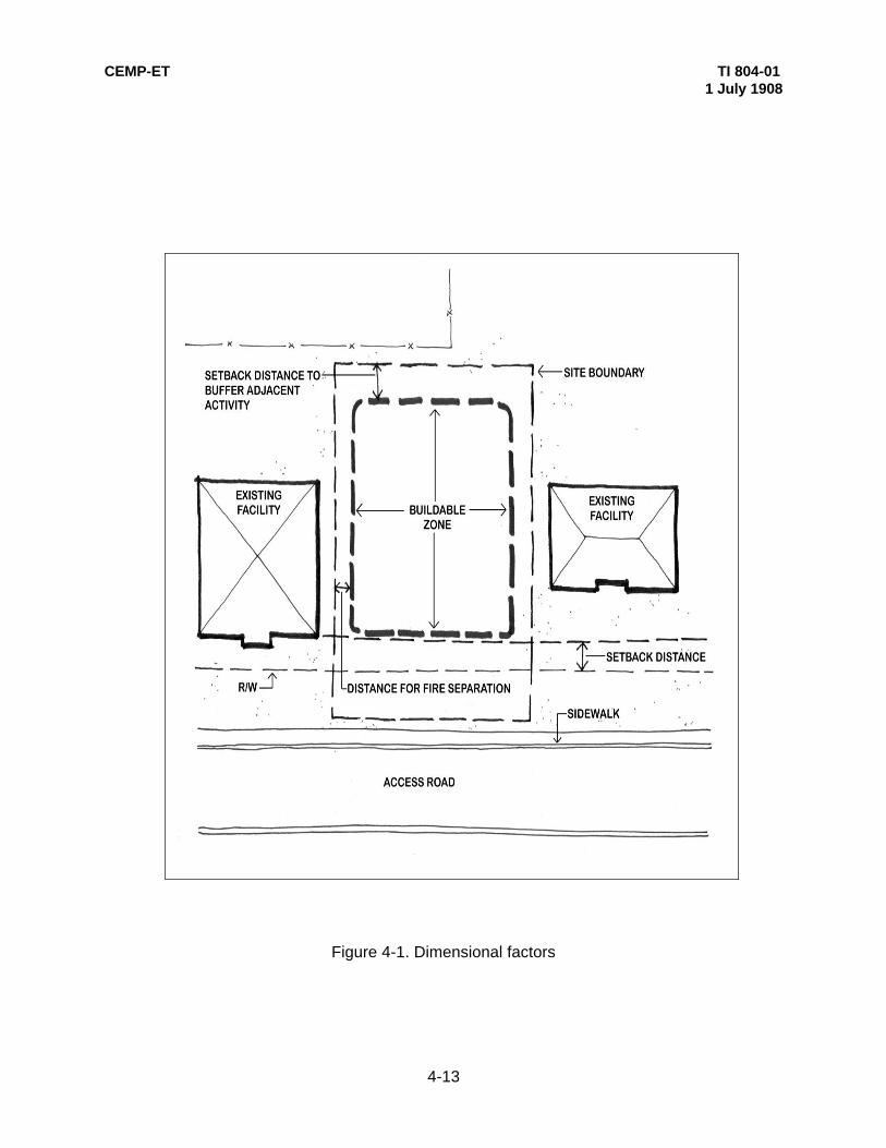
CEMP-ET TI 804-011 July 1908
4-13
Figure 4-1. Dimensional factors

CEMP-ET TI 804-011 July 1908
4-14
Figure 4-2. Solar orientation

CEMP-ET TI 804-011 July 1908
4-15
Figure 4-3. Slope orientation
Figure 4-4. Wind orientation

CEMP-ET TI 804-011 July 1998
4-16
Figure 4-5. Visual factors

4-17
CEMP-ET TI 804-011 July 1998
Figure 4-6. Vehicular circulation
Figure 4-7. Parking

4-18
CEMP-ET TI 804-011 July 1998
Figure 4-8. Dumpster location
Figure 4-9. Pedestrian circulation

CEMP-ET TI 804-011 July 1998
4-19
Figure 4-10. Sidewalk plans

CEMP-ET TI 804-011 July 1998
4-20
Figure 4-11. Minimize grading
Figure 4-12. Surface water management

CEMP-ET TI 804-011 July 1998
4-21
Figure 4-13. Detention, retention, and infiltration principles

CEMP-ET TI 804-011 July 1998
4-22
Figure 4-14. Erosion control
CEMP-ET TI 804-011 July 1908
A-1
APPENDIX A
REFERENCES
A-1. GOVERNMENT PUBLICATIONS
a. Department of the Army
Civil Engineering Research Foundation. “Recommendations for Incorporating Green BuildingConcepts Into USACE Guidance Documents”, Fall, 1995.
AEI Design CriteriaAR 200-2 Environmental Effects of Army ActionsAR 210-20 Master Planning for Army InstallationsAR 415-15 Military Construction, ArmyEI 00X001 Engineering Instructions, Guidance DocumentER 1110-1-2 Engineering and Design - Quality ManagementER 1110-1-4 Engineering and Design - Metric Measurements ER 1110-1-8152 Engineering and Design - Professional RegistrationER 1110-345-100 Engineering and Design - Design Policy for Military ConstructionTM 5-11-1 Electric Power Supply and DistributionTM 5-803-1 Installation Master PlanningTM 5-803-2 Planning in the Noise EnvironmentTM 5-803-5 Installation DesignTM 5-803-13 Landscape Design and PlantingTM 5-803-14 Site Planning and DesignTM 5-820-4 Drainage for Areas Other Than AirfieldsTM 5-822-2 General Provisions and Geometric Design for Roads, Streets,
Walks, and Open Storage Areas, TM 5-832-3 Security Engineering Final DesignTM 5-853-2 Security Engineering Concept Design
b. Department of the Air Force
Office of the Civil Engineer, Area Development Planning Bulletin, October 1991.
c. Department of Justice
Americans with Disabilities Act, Standards for Accessible Design, Washington D.C.: July 26, 1991
A-2. NONGOVERNMENT PUBLICATIONS
American Association of State Highway and Transportation Officials (AASHTO). A Policy onGeometric Design of Highways and Streets, Washington D.C.: AASHTO, 1984.
DeChiara, Joseph. Planning Design Criteria, New York: Reinhold, 1969.

CEMP-ET TI 804-011 July 1908
A-2
DeChiara, Joseph and Koppelman, Lee. Site Planning Standards, New York: McGraw Hill, 1978.
Harris, Charles W. and Dines, Nicholas T. Time-Saver Standards for Landscape Architecture,New York: McGraw-Hill, Inc., 1988.
Katz, Peter. The New Urbanism, New York: McGraw Hill, 1994.
Marsh, William M. Landscape Planning, 2nd ed, New York: John Wiley and Sons, Inc., 1991.
Ndubisi, Forster. Planning Implementation Tools and Techniques, Athens, Georgia: ICAD,1992.
Ramsey, Charles G. and Sleeper, Harold R. Architectural Graphic Standards, New York: Wiley,1970.
Rubenstein, Harvey M. A Guide to Site and Environmental Planning, New York: Wiley, 1969.
Steiner, Frederick. The Living Landscape: An Ecological Approach to Landscape Planning,New York: McGraw-Hill, Inc., 1991.