uetr analysis guideline
DESCRIPTION
UETR Analysis GuidelineTRANSCRIPT

UETR Analysis Guideline

UETR Analysis GL – Part 1/3

Content Description1. What is UETR?2. Interfaces in UTRAN3. UETR File location & File format4. Signalling Protocols5. UETR Messages and Measurements
RF Indicators: RSCP, Ec/Io, Tx Power, BLER, SIR, SIRerror
6. Call Flows1. RRC Establishment2. Registration
1. LAU (Location Area Update)2. RAU (Routing Area Update)
3. Soft/Softer Handover4. CS (Voice & Video) Call Establishment
1. UETR Call Flow CS Voice2. UETR Call Flow CS Video
5. PS R99 Call Establishment6. HSDPA Call Establishment & Primary Cell Change
1. UETR Call Flow HSDPA7. UETR Call Flow multi-RAB8. RANAP Iu Releases
7. Call Failures8. Tipps and Tricks – UETR Analysis methodologyAPPENDIX A
Abbreviations & UTRAN Measurement mapping

1. What is the UETR ?
• UETR = User Equipment Traffic Recording• UETR is a performance recording tool of inter-node events and
measurements for a specific UE (identified by its IMSI) that the RNC records.
• Only dedicated events with UE identifier is filtered and recorded in UETR.
• Events occurring before the internal UE identity has been assigned are not recorded.
• Events are recorded in 15min ROP. (UETR file size is 15min)
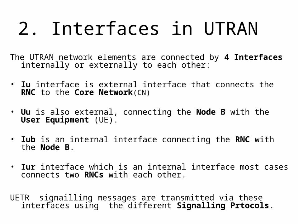
2. Interfaces in UTRANThe UTRAN network elements are connected by 4 Interfaces internally or
externally to each other:
• Iu interface is external interface that connects the RNC to the Core Network(CN)
• Uu is also external, connecting the Node B with the User Equipment (UE).
• Iub is an internal interface connecting the RNC with the Node B. • Iur interface which is an internal interface most cases connects two
RNCs with each other.
UETR signailling messages are transmitted via these interfaces using the different Signalling Prtocols.

3. UETR file location
• Where the UETR files are stored?
• Path to the UETR files.
• How to find the requested UETR file?

3. UETR file location 1/3
UETR files are located in the Sonar Server : http://10.200.26.56
Select the Traffic Recording Analysis (UETR/CTR) menu

3. UETR files location 2/3
Select the UETR menu

3. UETR files location 3/3Select the relevant IMSI from the POP-UP list
To see earlier files than visible in the “File” window click on “Earlier Files”
Select the RNC where the IMSI has been traced
Select the Start/End Dates of the UE trace
After all setting done click on “Perform Filter”
After UETR files have been filtered outDouble click on the UETR file name to open it.

3. UETR File Format
• What is the UETR file format in the Sonar User Interface?
• Message Types
• Message Directions
• Message End Points
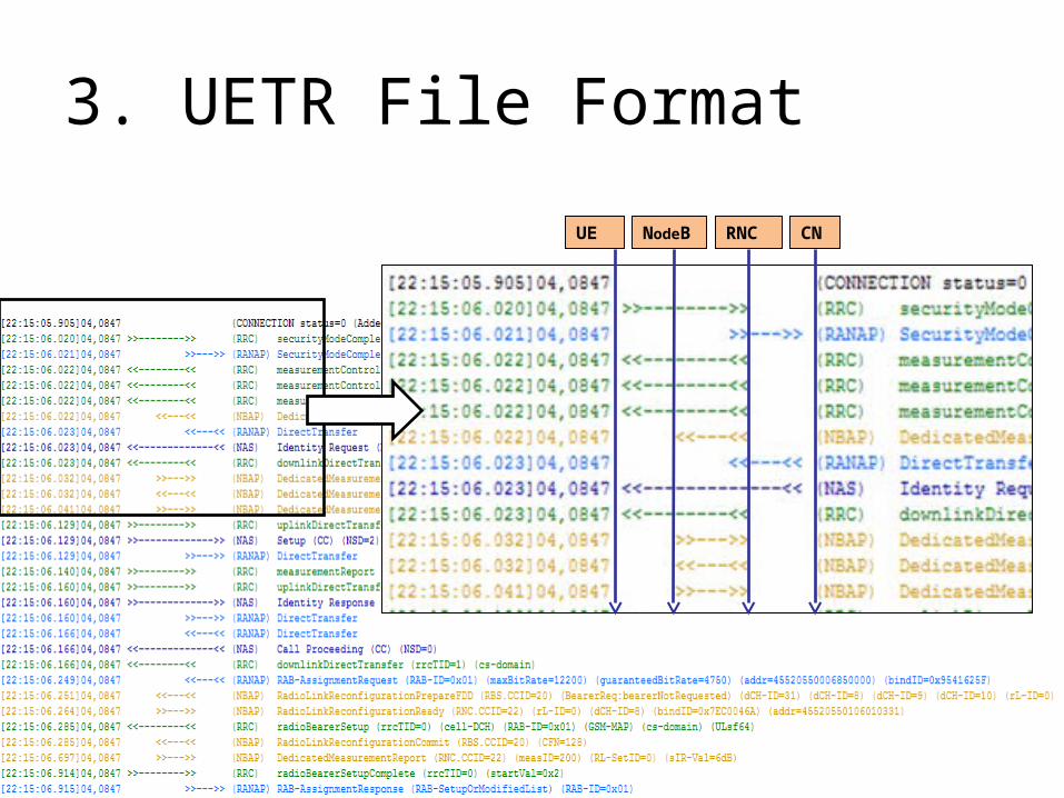
3. UETR File Format
UE NodeB RNC CN

4. Signalling Protocols in UETR 1/2The following Signalling Protocols can be found in UETR:
• RRC
The RRC (Radio Resource Control) handles the Layer 3 control signalling between the UE and RNC and performs functions for
– connection establishment and release, – broadcast of system information, – Radio Bearer establishment/reconfiguration and releases, – RRC Connection mobility procedures, – paging notification and release, – outer loop power control.
• NBAP
NBAP (Node B Application Part) is the signalling protocol responsible for the
control of the NodeB by the RNC. NBAP is carried over Iub.

4. Signalling Protocols in UETR 2/2• RNSAP
RNSAP (Radio Network Subsystem Application Part) is a signalling protocol
responsible for communications between RNCs. It is carried on the Iur interface
and provides functionality for
– SHO
– network configuration relocation.
• RANAP
RANAP (Radio Access Network Application Part) is a signaling protocol between
the Core Network (CN) and the RNC. RANAP is carried over Iu-interface. RANAP is
used for the following tasks:
– Relocation
– Radio Access Bearer Management
– Paging
– Transport of signalling between a UE and the Core Network (non-access stratum signalling)
• NAS
NAS (Non Access Stratum) is a functional layer running between the UE (User Equipment) and the CN (Core Network) and supports traffic and signalling messages between the CN and UE.

4. Signalling protocol messages -RANAP
RANAPRANAP (Radio Access Network Application Part) is a signaling
protocol between the Core Network (CN) and the RNC. RANAP is carried over Iu-interface. RANAP is
RNC CN

4. Signalling protocol messages -NBAP
NBAPNBAP (Node B Application Part) is the signalling protocol responsible for the control of the NodeB by the RNC. NBAP is carried over Iub.
NodeB RNC

4. Signalling protocol messages -RRC
UE RNC
RRCThe RRC (Radio Resource Control) handles the Layer 3 control signalling between the UE and RNC

4. Signalling protocol messages -RNSAP
SRNC DRCN
RNSAPRNSAP (Radio Network Subsystem Application Part) is a signalling protocol responsible for communications between RNCs. It is carried on the Iur interface
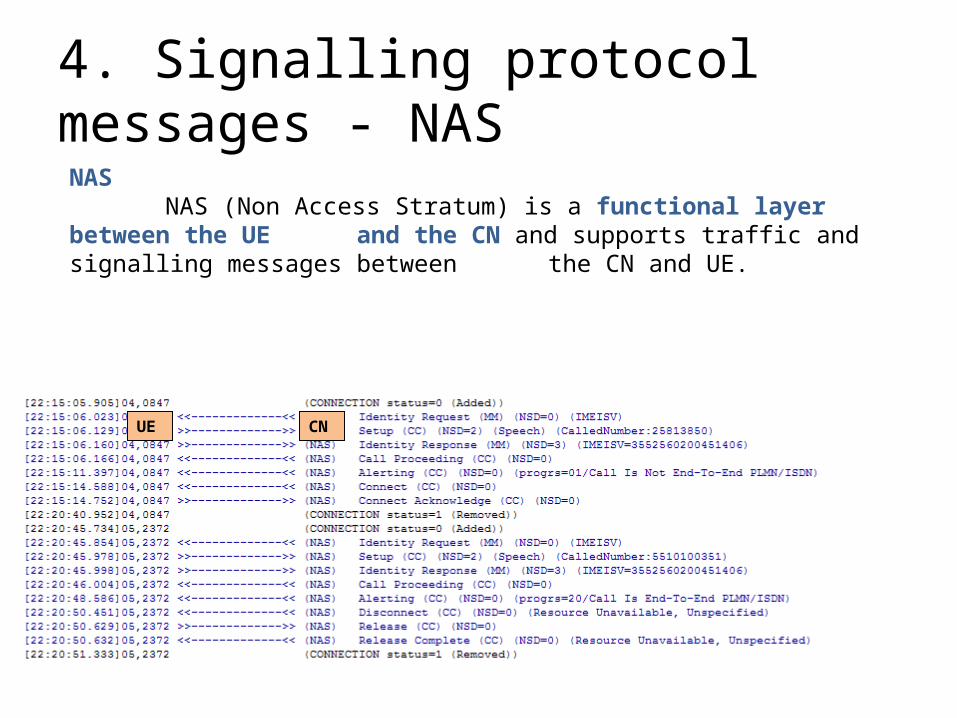
4. Signalling protocol messages - NAS
UE CN
NASNAS (Non Access Stratum) is a functional layer between the UE and the CN and supports traffic and signalling messages between the CN and UE.
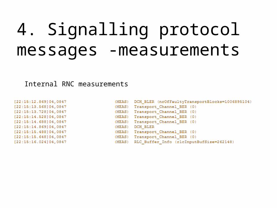
4. Signalling protocol messages -measurements
Internal RNC measurements
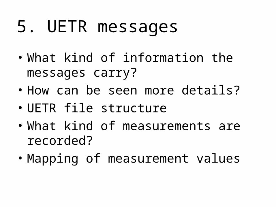
5. UETR messages
• What kind of information the messages carry?
• How can be seen more details?
• UETR file structure
• What kind of measurements are recorded?
• Mapping of measurement values
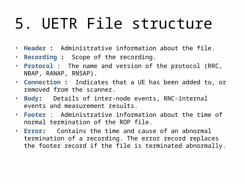
5. UETR File structure
• Header : Administrative information about the file.
• Recording : Scope of the recording.
• Protocol : The name and version of the protocol (RRC, NBAP, RANAP, RNSAP).
• Connection : Indicates that a UE has been added to, or removed from the scanner.
• Body: Details of inter-node events, RNC-internal events and measurement results.
• Footer : Administrative information about the time of normal termination of the ROP file.
• Error: Contains the time and cause of an abnormal termination of a recording. The error record replaces the footer record if the file is terminated abnormally.

5. UETR Event Message Example
Event Message Header
Event Message Body
Parameter Value (Mapped)(For Mapping details refer to Appendix A )
Measured Parameter
Message details

5. Event Message Header EVENT : 234 = ID number of the Event
Hour: 22 Minute: 15 Second: 06 Millisecond: 140 = TimeStamp of the event
Event_ID: 8 = ID of the event (eg.: Active Set Update = eventID: 0)
RncModuleId: 4 = Identity of the RNC module from which the event is reported.
UeContextId: 847 = Initial UE context (internal identifier) number.
C_ID_1: 40331 = Cell identity of the first cell in the active set
RNC_ID_1: 1006 = Identity of the controlling RNC (CRNC) for the first cell in the active set.
C_ID_2: EVENT_VALUE_INVALID = Cell identity of the 2nd cell in the active set
RNC_ID_2: EVENT_VALUE_INVALID = ID of the controlRNC (CRNC) for the 2nd cell in the active set.
C_ID_3: EVENT_VALUE_INVALID = Cell identity of the 3rd cell in the active set
RNC_ID_3: EVENT_VALUE_INVALID = ID of the controlling RNC (CRNC) for the 3rd cell in the active set.
C_ID_4: EVENT_VALUE_INVALID = Cell identity of the 4th cell in the active set
RNC_ID_4: EVENT_VALUE_INVALID = ID of the controlling RNC (CRNC) for the 4th cell in the active set.
Direction: RECEIVED = Direction of the recorded event, measurement (Received / Sent)
ProtocolID: 0 = RRC=0 / NBAP=1 / RANAP=2 / RNSAP= 4
PDU-type: Type of the PDU
Message length: Length of the message
Coded Message:

5. UETR Event Measurements
The UETR Measurements can be grouped into:• NBAP measurements• UE measurements• RNC measurements
The following chapters present only measurements which can be found in the UETR records.

5. NBAP Measurements - SIR
SIR• Uplink Signal-to-Interference Ratio (SIR) per radio link set (RL-Set),
measured on Dedicated Physical Control Channel (DPCCH) after radio link combination in the Node B.
• NodeB measures the Pilot Bit power of DPCCH and calculates the Signal-to –Interference ratio (SIR) per RL-set. This is compared to SIRtarget and based on the result TPC sent to UE (increase/decrease TxPwr).
• Range: [-11..20] dB by step of 0.5 dB• The optimal value for the SIR is around 3-6 dB.• High SIR value indicates the presence high UL Interference.• Low SIR triggers PC algorithm to order changing UeTxPwr for higher
value -> Increase of UL Interference.Example message:

5. NBAP Measurements - SIRerror
SIR ERROR• SIRerror = SIR - SIRtarget. • SIRerror shows the gap between the assigned SIRtarget and measured
SIR. Value of SIRerror per connection shows how well the SRNC is able to adjust UE Tx Pwr, which shows the accuracy of Power Control.
• SIR should follow the SIRtarget -> SIRerror should present 0 value.• SIRerror measured on Dedicated Physical Control Channel (DPCCH)
after radio link combination in the Node B and reported for all RL-Sets relating to the UE connections being recorded.
• Range: [-31..31] dB by step of 0.5 dB• (SIRtarget is adjusted by UL outer-loop power control algorithm and
used for closed-loop PC. )
Example message:

5. NBAP Measurements – Tx Power• TRANSMITTED CODE POWER• Transmitted code power is the transmitted power measured on the
pilot bits of one channelization code on one scrambling code on one Dedicated Physical Channel (DPCH).
• One average value is reported for all DPCHs relating to the UE connections.
• This is the power allocated per connection. Based on this measurement
DL load of UE per connection can be estimated.• Range: [-10..46] dBm by step of 0.5 dB• The higher TCP value indicates worse RF conditions and higher DL-
code Pwr load since pilot channel has to transmit with higher power.
Example message:

5. UE Measurement Report
UE performs various measurements. The measurements are sent in the MR – Measurement Report.The measurements are started by sending the RRC message: MEASUREMENT CONTROL to a UE, specifying: measurement quantity, measurement id and reporting period.
UE measurements: DL TRANSPORT CHANNEL BLERUE Tx POWER DL CPICH Ec/No DL CPICH RSCP

5. UE Measurement Report - BLERDOWNLINK TRANSPORT CHANNEL BLER• (BLER = Block Error Rate)• BLER is estimation of Transport Channel Block Error Rate in DL DCH, based
on evaluating CRC on each Trabsport Block after Radio Link combination.• BLER is long-time average block error rate calculated from transport blocks.• Range: [0…1] by setp of 0.065• The lower BLER value indicates better Transport Cahnnel quality. • There is NO BLER measurement in HSDPA.
Measurement Control message defines which
MR will report the UE Tx Pwr and which one
The DL-Transport Ch. BLER. (for more details see Slide of
MeasurementControl)
message measurementReport : { measurementIdentity 7, measuredResults qualityMeasuredResults : { blerMeasurementResultsList { { transportChannelIdentity 31, dl-TransportChannelBLER 0 } }, modeSpecificInfo fdd : NULL } }
Message details

5. UE Measurement Report - DL CPICH Ec/No
DL CPICH Ec/No • CPICH_Ec/No is the received energy per chip divided by the power
density in the band. Measurement is performed on the Primary CPICH (P-CPICH).
• In more simple : Ec/No = P-CPICH_RSCP / UTRA_Carrier_RSSI• DL CPICH Ec/No (Ec/Io) is the DL quality indicator of the P-CPICH.• DL CPICH Ec/No measurement is used for cell selection and re-selection
procedure, active set update, handover triggers, downlink power setting.• Range: [-24..0] dB by step of 1 dB. (see mapping in Appendix)• The higher the Ec/No the better the P-CPICH quality.• DL CPICH Ec/No > -8dB the connection considered good.• DL CPICH Ec/No < -14dB triggers CM and Inter-RAT HO/CC.• Measurement values are in MR (measID=1): (for details go to next slide)

5. UE Measurement Report - DL CPICH RSCP DL CPICH RSCP• DL CPICH RSCP is the Received Signal Code Power on one channelization code. Measured on the bits of the Primary
CPICH.• DL CPICH RSCP measurement can be used for cell selection and reselection for handover preparation for power control
and for path loss calculation.• Measurement values are in MR (measID=1):
• which is initiated by MeasurementControl :
• Range: [-115..-25] dBm by step of 1 dB
(see for mapping Appendix A)• The higher DL CPICH RSCP value indicates
better RF conditions.
Mapped Values
MR (measID=1) message details
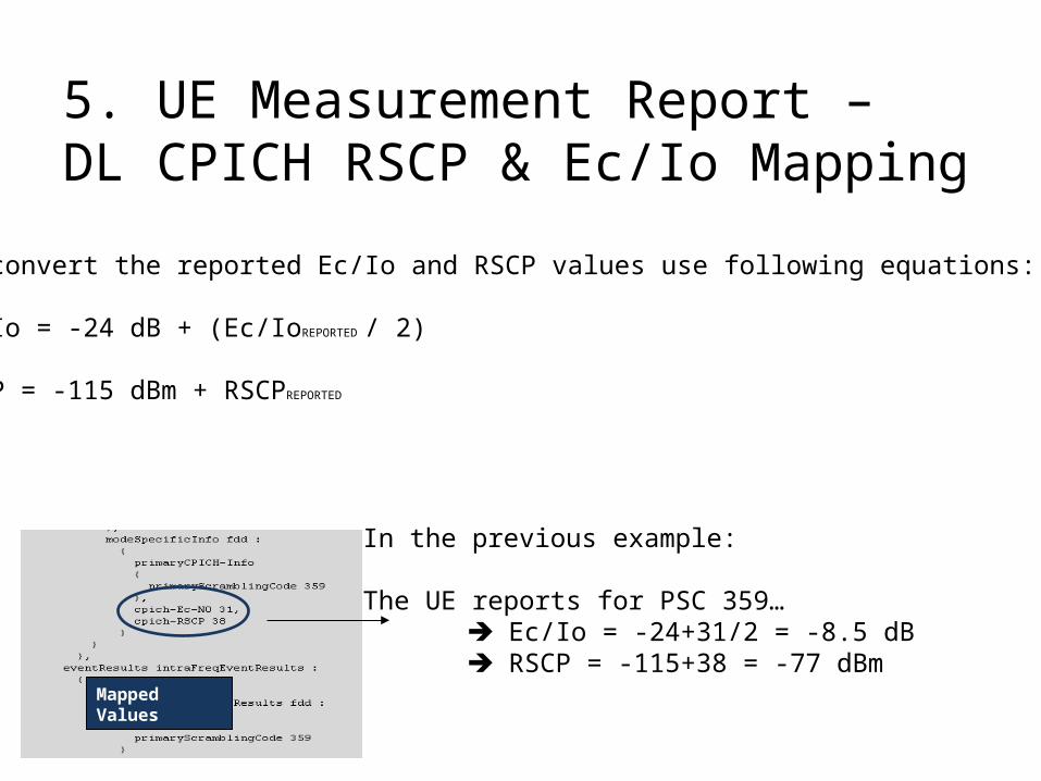
5. UE Measurement Report – DL CPICH RSCP & Ec/Io Mapping
Mapped Values
To convert the reported Ec/Io and RSCP values use following equations:
Ec/Io = -24 dB + (Ec/IoREPORTED / 2)
RSCP = -115 dBm + RSCPREPORTED
In the previous example:
The UE reports for PSC 359… Ec/Io = -24+31/2 = -8.5 dB RSCP = -115+38 = -77 dBm

5. UE Measurement Report – UE Tx Power
UE Tx POWER • The UE transmitted power is the total power transmitted by the UE
on one carrier.• UE Tx power measurement is used for power management and
handover preparation.• Range: [-50..33] dBm by step of 1 dB.• The lower the UE Tx power the lower the UL Interference since UE
is not ordered by PC algorithm to use high power.
Measurement Control message defines which
MR will report the UE Tx Pwr and which one
The DL-Transport Ch. BLER. (for more details see Slide 31)

5. Measurement ControlEach MR has its own function:
•qualityMeasuredResults (measID=7) [ e.g.: dl-TransportChannelBLER ]•ue-InternalMeasuredResults (measID=8) [ e.g.: ue-TransmittedPower ]•intraFreqMeasuredResultsList (measID=1) or (measID=6) [e.g.: ev1a / e1b …]
Measurement Control allocates the MR functions to the measurementReports

6. Call flows
Call flow presented:
• RRC Establishment (all RABs)
• Call Setup
• RAB allocation
• Active Set Update
• Compressed Mode
• Inter-RAT HO
• Call Release

6.1. RRC Establishement
1. Call Flows
UE NodeB RNCRACH / RRC Connection RequestRRC RRC
NBAP NBAP
NBAPNBAP
Radio Link Setup Request
Radio Link Setup Response
RRCRRC
RRC RRC
FACH / RRC Connection Setup
DCH / RRC Connection Complete
DCH / Measurement Control (soft-HO parameters, Neighbours) RRCRRC
No soft-Handover(only 1 cell in Active Set)
•The first two messages are sent in common channels (RACH and FACH), since the dedicated channel is not created on this stage yet
•This call flow is the same whatever the type of the call is going to be established
•RRC Establishment does not appear in UETR (UETR starts with security mode command, once UE has been given an ID)

Security Mode Command
Security Mode Command Complete
Authentication Request
Authentication Response
Radio Link Setup Request
Radio Link Setup Response
6.2.1 Registration – Location Area Update (I)
UE NodeB RNCRACH / RRC Connection Request: RegistrationRRC RRC
NBAP NBAP
NBAPNBAP
RRCRRC
RRC RRC
FACH / RRC Connection Setup
RRC Connection Complete
Measurement Control (soft-HO parameters, Neighbours) RRCRRC
RRC
MM
Initial Direct Transfer - Location Updating RequestRRC
MM
MSC/VLR
MMMM
1. Call Flows
MM MM
MM MM

TMSI Reallocation Complete
TMSI Reallocation Command
6.2.1 Registration – Location Area Update (II)
UE NodeB RNC
RRCRRC Direct Transfer – Location Update Complete
1. Call Flows
MM MM
MM MM
MSC/VLR
Security Mode Command
Security Mode Command Complete
Authentication and Ciphering Request
Authentication and Ciphering Response
Radio Link Setup Request
Radio Link Setup Response
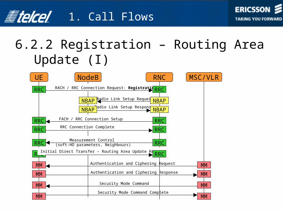
6.2.2 Registration – Routing Area Update (I)
UE NodeB RNCRACH / RRC Connection Request: RegistrationRRC RRC
NBAP NBAP
NBAPNBAP
RRCRRC
RRC RRC
FACH / RRC Connection Setup
RRC Connection Complete
Measurement Control (soft-HO parameters, Neighbours) RRCRRC
RRC
MM
Initial Direct Transfer – Routing Area Update RequestRRC
MM
MMMM
1. Call Flows
MM MM
MM MM
MSC/VLR

Direct Transfer – Routing Area Update Complete
6.2.2 Registration – Routing Area Update (II)
UE NodeB RNC
RRCRRC Direct Transfer – Routing Area Update Accept
1. Call Flows
RRC RRC
MSC/VLR

6.3. Soft And Softer HO
1. Call Flows
UE NodeB RNCRRC / Measurement Report: e1aRRC RRC
NBAP NBAP
NBAPNBAP
Radio Link Setup Request
Radio Link Setup Response
RRCRRC
RRC RRC
RRC / Active Set Update
RRC / Active Set Update Complete
NBAP NBAPRadio Link Restore Indication
At Softer HO instead of Radio Link Setup Request /Response there is a Radio Link Addition Request /Response.There is no Radio Link Restoration Indication message sent neither.

6.4. CS (Voice & Video) Establishment (I)
1. Call Flows
Security Mode Command
Security Mode Command Complete
Authentication and Ciphering Request
Authentication and Ciphering Response
Radio Link Setup Request
Radio Link Setup Response
UE NodeB RNCRACH / RRC Connection Request: (CS Voice or Video)RRC RRC
NBAP NBAP
NBAPNBAP
RRCRRC
RRC RRC
FACH / RRC Connection Setup
RRC Connection Complete
Measurement Control (soft-HO parameters, Neighbours) RRCRRC
RRC
MM
Initial Direct Transfer – CM Service RequestRRC
MM
MMMM
MM MM
MM MM
MSC/VLR

Direct Transfer – Connect Complete
Direct Transfer - Connect
RAB Assignment Response
RAB Assignment Request
6.4. CS (Voice & Video) Establishment (II)
1. Call Flows
UE NodeB RNCDirect Transfer - SetupRRC RRC
RRCRRC
RRC RRC
Direct Transfer – Call Proceeding
RB Setup Request
RB Setup CompleteRRCRRC
RANAP RANAP
RANAP RANAP
RRC RRCDirect Transfer - Alerting
RRC RRC
RRC RRC
MSC/VLR

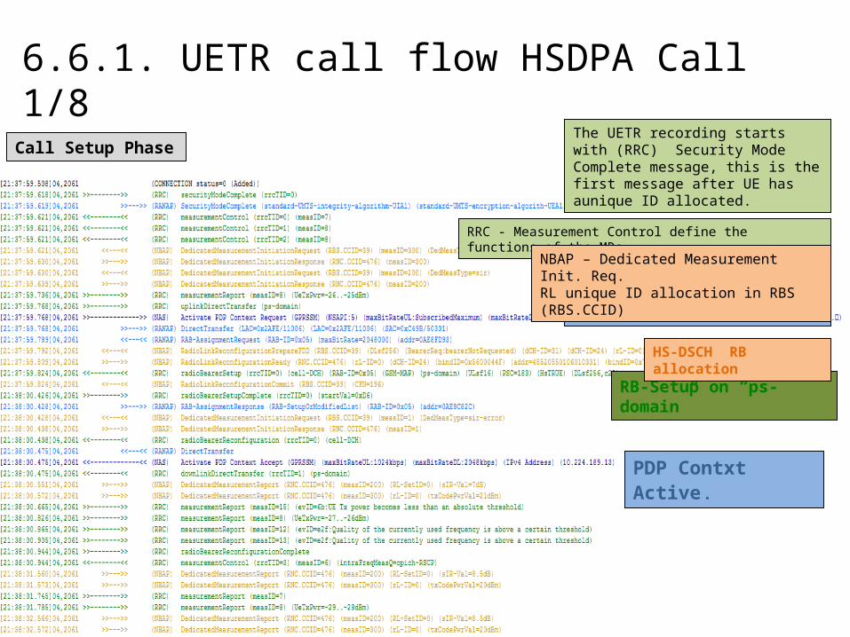
6.4.1. UETR Call Flow CS-Speech (UE Originated) 1/12
Call Setup Phase
NAS – Setup message indicates the Service type and other details of the call requested by the UE.
NBAP – Dedicated Measurement Init. Req.RL unique ID allocation in RBS (RBS.CCID)
NBAP – Dedicated Measurement Init. Req.RL unique ID allocation in RNC (RNC.CCID)
RRC - Measurement Control define the functions of the MRs.
RANAP – RAB assignment Req.
RB Setup on “cs-domain”
The UETR recording starts with (RRC) Security Mode Complete message, this is the first message after UE has a unique ID allocated.

6.4.1. UETR Call Flow CS-Speech 2/11
SecurityModeComplete (RRC) is the first dedicated message of the call (CS/PS) in UETR file. This is the response to SecurityModeCommand (RANAP) to allocate unique ID for the UE.
The CCID (communicationContext ID) uniquely identifies the RL during the entire call in the ControlRNC. (This procedure is used also to trigger of ciphering or to command the change of the cipher key.)
RNC.CCID= Identifies the RL during the whole communication within the controlRNC
RBS.CCID= Identifies the RL in the NodeB (RBS)
The Measurement Control messages define the functions of the MRs (which one is for the UE Tx Pwr and which one the DL Transport BLER, which one is for RL-addition/deletion (ev1a/ev1b….) (More info of MCs in slide 31)
Direct Transfer messages (RANAP) carry UE-CN signalling messages (like MM or CC messages).

6.4.1. UETR Call Flow CS-Speech 3/12
Dedicated Measurement Initial Request (NBAP) procedure is used by a CRNC to request the initiation of measurements on dedicated resources in a NodeB.
Dedicated Measurement Initial Response (NBAP) is the response to Dedicated Measurement Init Req. with the RNC.CCID (see previous slide)
The RNC.CCID the unique ID of the RL in the RNC. Lost RL ID due to any synch.Failure can be found here (this is the first appearance of the RL ID.)
DL Direct Transfer (RRC) procedure is used in both downlink and uplink to carry all higher layer (NAS) messages over the radio interface. It can also be used to establish and release signalling connections.
RAB Assignment Request (RANAP) is sent by CN to RNC to request Establishment, Modification or Release of one or more RABS to the same UE.
RadioLinkReconfigurationPrepare (NBAP) procedure is used to prepare a new configuration of all Radio Links related to one UE-UTRAN connection within a Node B.
Radio Bearer Setup (RRC) is the procedure to establish new radio bearer(s).

6.4.1. UETR Call Flow CS-Speech 4/12
Alerting – Connect Phase
RB reconfiguration Phase RB Reconfiguration for the negotiated QoS Bearer.
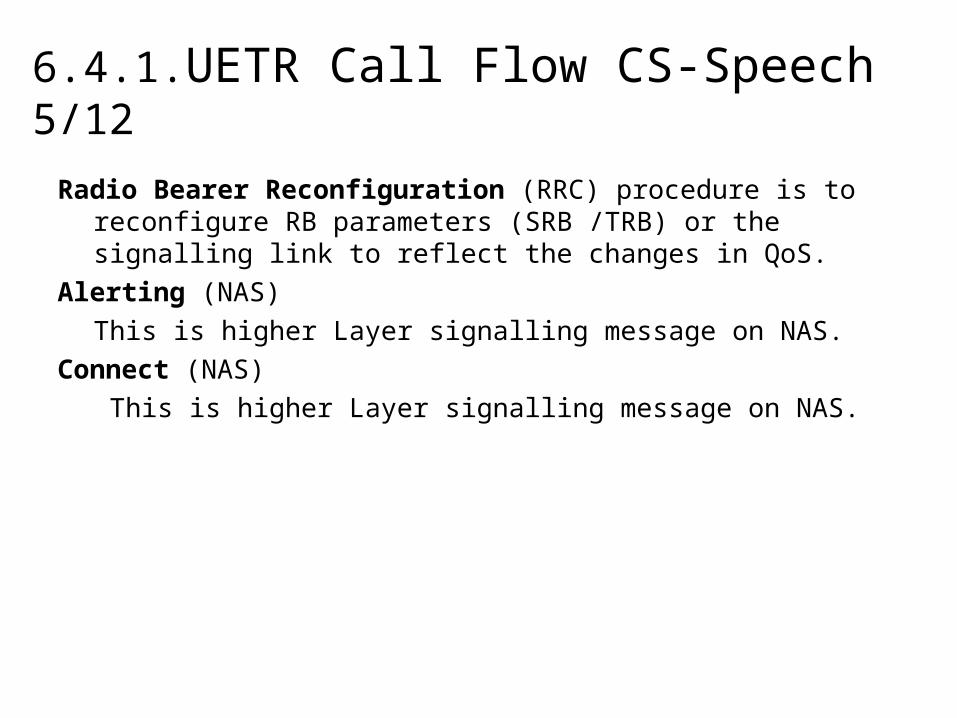
6.4.1.UETR Call Flow CS-Speech 5/12
Radio Bearer Reconfiguration (RRC) procedure is to reconfigure RB parameters (SRB /TRB) or the signalling link to reflect the changes in QoS.
Alerting (NAS)
This is higher Layer signalling message on NAS.
Connect (NAS)
This is higher Layer signalling message on NAS.

6.4.1. UETR Call Flow CS-Speech 6/12
1
2
6
3
4
5

6.4.1. UETR Call Flow CS-Speech 6/12
Meaurement Report (measID=1) assigned by Measurement Control presents cpich-Ec-N0 and cpich-RSCP measurements of the measured PSCs.
In case of measured result is above/below e1a or e1b criteria -> RL addition or removal is initiated. (ASU is initiated during e1a/e1b/e1c/e1d events)
RadioLinkAdditionRequest (NBAP) is used for establishing the necessary resources in the Node B for one or more additional RLs towards a UE when there is already a Node B communication context for this UE in the NodeB.
This message includes the Initial DL Transm. Pwr and DL Channelization Pwr too.
RadioLinkDeletionRequest (NBAP) is used for deleting RL resources in the Node B
ActiveSetUpdate (RRC) procedure is to update the active set of the connection between the UE and UTRAN. The UE keeps on using the old RLs while allocating the new RLs.
At Hard HO case the ActiveSetUpdate message has to contain additional “physical CH information elements”: frequency info, UL-RR, DL-RR and other optional parameters for the target phyCH configuration.

6.4.1. UETR Call Flow CS-Speech 7/12
Compressed Mode 1
Phy.Ch.Reconfiguration for entering into
Compressed Mode.
Measurement Control message to start measurements on Inter-RAT cells (set-up 2G cell list)

6.4.1. UETR Call Flow CS-Speech 8/12
Compressed Mode 2
RNC sends Iu-Release Request (RANAP) to CN due to Connection Relocation.
When Iu-Release succefully done the RRC connection is still open for sending IRAT events.

6.4.1. UETR Call Flow CS-Speech 9/12
Compressed Mode 3
After Iu-Release UE sends e2d event messages to the RNC on RRC.
In this case IRAT-HO succesfully has been done -> Connection released in UTRAN and the call continous in 2G. (event3a will be sent for HO execution phase)
IRAT-HO preparation+

6.4.1. UETR Call Flow CS-Speech 10/12
• Compressed Mode is initiated to preform UE measurements on Inter-Frequency or Inter-RAT cells.
• Compressed Mode is triggered by e2d event (UTRAN EcNo or RSCP is bellow of the e2d threshold (individual thersholds for EcNo and RSCP) + histeresys/2 during “timeToTrigger2d” timer.
• Compressed mode is stopped by e2f event when measured EcNo or RSCP is above e2f criteria during “timeToTrigger2f” timer.
• If the connection is using HS-DSCH then a reconfiguration attempt to DCH is triggered first (Physical Channel reconfiuration). When the connection has been moved to DCH the IRAT HO attempt (event e3a) can proceed.

6.4.1. UETR Call Flow CS-Speech 11/12
Call Release Phase
The normal call release initiated by Iu-release request (RANAP) with cause code: “normal release”

6.4.1. UETR Call Flow CS-Speech 12/12
Iu-ReleaseRequest (cause:radioNetwork/release-due-to-UE-generated-signalling-connection-release) (RANAP) is sent by the RNC to CN request for release of Iu connection.
The Request contains the Release Cause as well.
Iu-ReleaseCommand (cause:radioNetwork/release-due-to-UE-generated-signalling-connection-release) (RANAP) is sent by CN to order the RNC to release all resources related to Iu connection.
Iu-ReleaseComplete (RANAP) is sent by the RNC as the response to CN Iu Release Command.

6.4.2. UETR Call Flow CS-Video Call
• Call flow for CS-Video Call Mobile Originated
• Which message the UETR scanning starts with?
• What is the main difference from CS-Voice call?
• What kind of information are transferred in Call Setup?

6.4.2. UETR Call Flow CS-Video Call 1/3Call Setup Phase
NAS – Setup message indicates the Service type and other details of the call requested by the UE.
NBAP – Dedicated Measurement Init. Req.RL unique ID allocation in RBS (RBS.CCID)
NBAP – Dedicated Measurement Init. Req.RL unique ID allocation in RNC (RNC.CCID)
RRC - Measurement Control define the functions of the MRs.
RANAP – RAB assignment Req.
The UETR recording starts with (RRC) Security Mode Complete message, this is the first message after UE has a unique ID allocated.
RB Setup on “cs-domain”
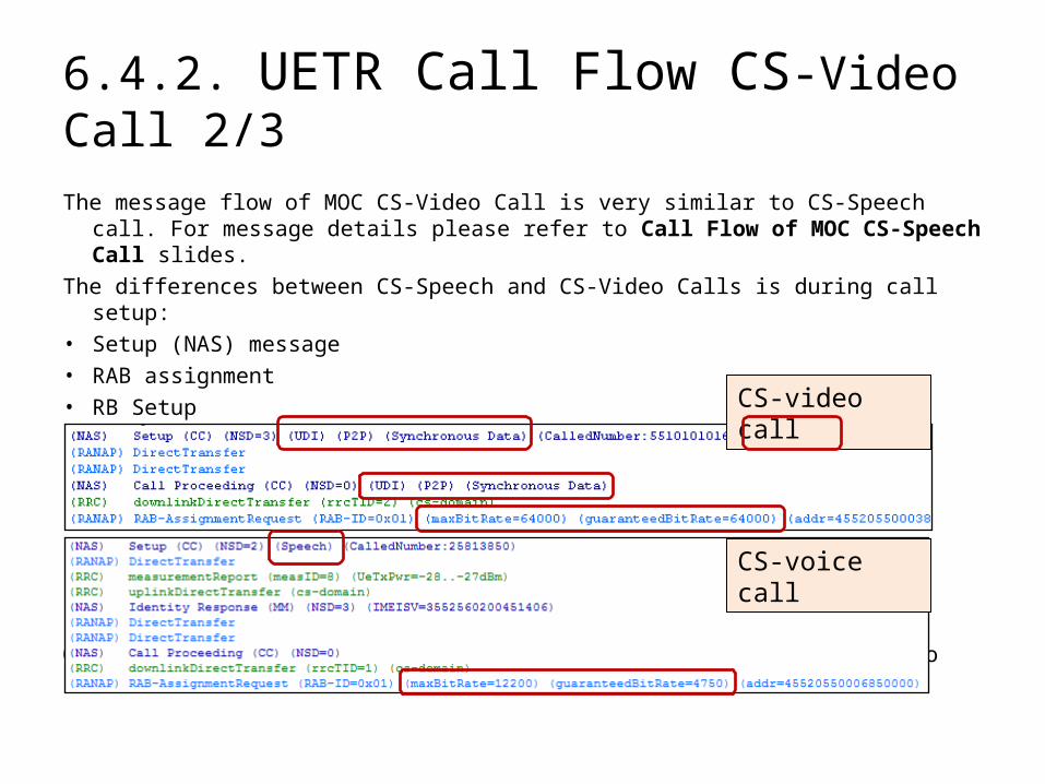
6.4.2. UETR Call Flow CS-Video Call 2/3
The message flow of MOC CS-Video Call is very similar to CS-Speech call. For message details please refer to Call Flow of MOC CS-Speech Call slides.
The differences between CS-Speech and CS-Video Calls is during call setup:
• Setup (NAS) message
• RAB assignment
• RB Setup
Other messages (CM, ASU,…) are same to CS-Speech Call flow, thus no details can be found here on this matter.
CS-voice call
CS-video call
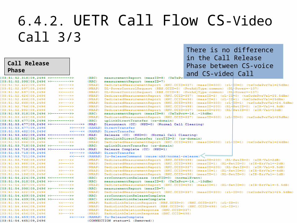
6.4.2. UETR Call Flow CS-Video Call 3/3
Call Release Phase
There is no difference in the Call Release Phase between CS-voice and CS-video Call
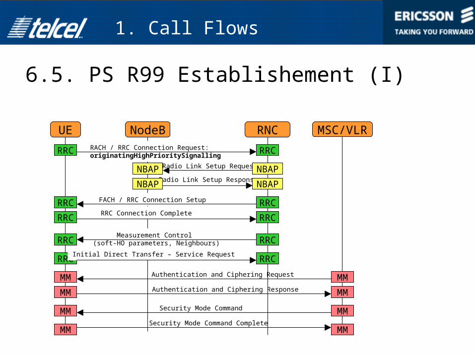
6.5. PS R99 Establishement (I)
1. Call Flows
Security Mode Command
Security Mode Command Complete
Authentication and Ciphering Request
Authentication and Ciphering Response
Radio Link Setup Request
Radio Link Setup Response
UE NodeB RNCRACH / RRC Connection Request: originatingHighPrioritySignalling
RRC RRC
NBAP NBAP
NBAPNBAP
RRCRRC
RRC RRC
FACH / RRC Connection Setup
RRC Connection Complete
Measurement Control (soft-HO parameters, Neighbours) RRCRRC
RRC
MM
Initial Direct Transfer – Service RequestRRC
MM
MMMM
MM MM
MM MM
MSC/VLR

RAB Assignment Response
RAB Assignment Request
6.5. PS R99 Establishment (II)
1. Call Flows
UE NodeB RNCDirect Transfer – Activate PDP Context RequestRRC RRC
RRC RRCRB Setup Request
RB Setup Complete RRCRRC
RANAP RANAP
RANAP RANAP
RRC RRCDirect Transfer – Activate PDP Context Accept
MSC/VLR

6.6. HSDPA Call Establishement (I)
1. Call Flows
Security Mode Command
Security Mode Command Complete
Authentication and Ciphering Request
Authentication and Ciphering Response
Radio Link Setup Request
Radio Link Setup Response
UE NodeB RNCRACH / RRC Connection Request: RegistrationRRC RRC
NBAP NBAP
NBAPNBAP
RRCRRC
RRC RRC
FACH / RRC Connection Setup
RRC Connection Complete
Measurement Control (soft-HO parameters, Neighbours) RRCRRC
RRC
MM
Initial Direct Transfer - Location Updating RequestRRC
MM
MMMM
MM MM
MM MM
MSC/VLR

RAB Assignment Response
RAB Assignment Request (SF: DL256 / UL16)
6.6. HSDPA Establishment (II)
1. Call Flows
UE NodeB RNCDirect Transfer – Activate PDP Context RequestRRC RRC
RRC RRCRB Setup Request
RB Setup Complete RRCRRC
RANAP RANAP
RANAP RANAP
RRC RRCDirect Transfer – Activate PDP Context Accept
MSC/VLR

6.6. HSDPA Primary Cell Change
1. Call Flows
UE NodeB RNCMeasurement Report: e1dRRC RRC
RRC RRCPhysical channel reconfiguration
Physical channel reconfiguration CompleteRRCRRC
NBAP NBAP
NBAPNBAP
Radio Link Reconf Prepare
Radio Link Reconf Ready
NBAP NBAPRadio Link Reconf Commit

6.6.1. UETR call flow HSDPA Call
• Which message the UETR scanning starts with?• What kind of messages can be seen?• What kind of information they carry?• Differences in Call Setup phase.• RB Reconfiguration.• Phy Channel Reconfiguration.• Active Set Update. (Intra/Inter-NodeB, Inter-RNC)
6.6.1. UETR call flow HSDPA Call 1/8
Call Setup Phase
RB-Setup on “ps-domain”
PDP Contxt Req.
PDP Contxt Active.
HS-DSCH RB allocation
The UETR recording starts with (RRC) Security Mode Complete message, this is the first message after UE has aunique ID allocated.
RRC - Measurement Control define the functions of the MRs.
NBAP – Dedicated Measurement Init. Req.RL unique ID allocation in RBS (RBS.CCID)

6.6.1. UETR call flow HSDPA Call 2/8
• During PS call setup UE requests PDP Context Activation in NAS message while in CS (voice/video) setup the UE request is a call Setup (NAS).
• RAB assignment allocates different RAB type (64/HS, 384/HS, 64/64,…)• RB Setup allocates different type of RB (64kbps, 128kbps, 384kbps, HS)
PS-call
CS-voice call

6.6.1. UETR call flow HSDPA Call 3/8
Example: Radio Bearer Reconfiguration from Cell-DCH to Cell-FACH for Cell Update due to Cell Reselection
RB Reconfiguration from Cell-DCH to Cell-FACH
Cell Update due to Cell Reselection on Cell-FACH
RB Reconfig. from Cell-FACH to Cell-DCH
RB Reconfiguration

6.6.1. UETR call flow HSDPA Call 4/8
Physical Channel Reconfiguration is done in HSDPA for:
• Cell Change procedure (intra/inter-NodeB)• Upswitch/Downswitch due to RF conditions:• Upswitch/Downswitch due to Throughput:• Crossing RNC border:• IRAT-HO/CC:

6.6.1. UETR call flow HSDPA Call 5/8
Physical Channel Reconfiguration
Cell Change after Active Set Update
Active Set UpdateCell Change after Active Set Update – Intra-NodeB C.C.
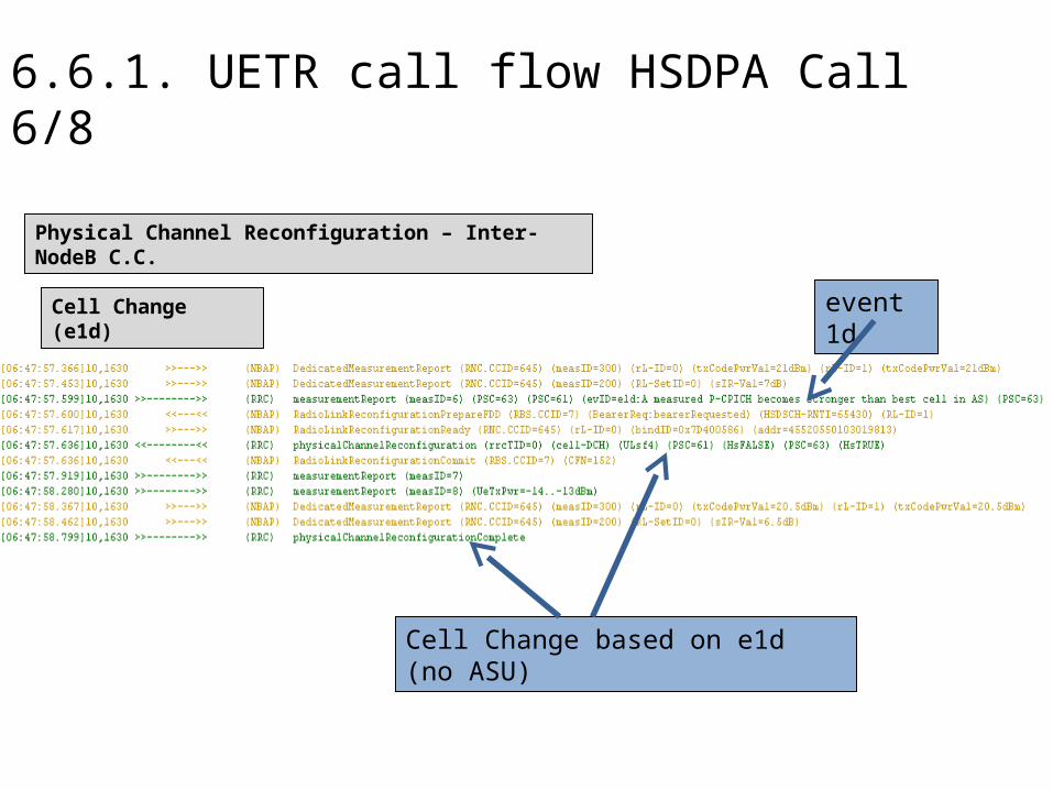
6.6.1. UETR call flow HSDPA Call 6/8
Physical Channel Reconfiguration – Inter-NodeB C.C.
Cell Change (e1d)
Cell Change based on e1d (no ASU)
event 1d

6.6.1. UETR call flow HSDPA Call 7/8Physical Channel Reconfiguration
Reconfiguration over Iur – Inter-RNC C.C.
Phy Ch Reconfiguration From HS-DSCH to DCH due to RL addition from DRNC
Active Set Update : Add RL from DRNC
Phy Ch Reconfiguration: Best Server Cell Change in AS.=> DRNC cell became best.
Active Set Update event in DRNC
There is NO Phy Reconfiguration for Upswitch to HS-DSCH in DRNC!

6.6.1. UETR call flow HSDPA Call 8/8
Call Release Phase Normal Iu-Release process of PS (HS) connection

6.7. UETR Call Flow CS/PS Multi-RAB 1/6
Set-up of CS-RAB
CS-Speech Call is Requested.

6.7. UETR Call Flow CS/PS Multi-RAB 2/6
CS-RAB allocation
CS-Speech RAB is Requested.
CS-Speech RAB is Set up.
CS-RB Setup
CS-Speech Call Established, Alerting

6.7. UETR Call Flow CS/PS Multi-RAB 3/6
PS-RAB allocation
PS RAB is Requested.
CS-Speech RAB is Set up.
PS-RB Setup

6.7. UETR Call Flow CS/PS Multi-RAB 4/6
PS-RAB release
PS RAB disconnect Request from CN via NAS.
PS RAB release Command from CN.
PS-RB release
PS RAB release Complete

6.7. UETR Call Flow CS/PS Multi-RAB 5/6
CS-RAB release
CS RAB release Request.
CS RAB release Complete
However RadioLinks coud not been Deleted.

6.7. UETR Call Flow CS/PS Multi-RAB 6/6
Iu-Release Failure
After 7 rrConnectionRelease Requests finally both RLs have been deleted
RadioLinks coud not been Deleted. (synch.Failure)

6.8. Iu-Release Cases
Examples of Iu-Releases:
• Normal Release
• UE-generated-signalling-release
• UE-inactivity
• Radio-connection-with-UE-Lost
• OM-Intervention

6.8. Iu-Release cause: Normal-release
The Iu-Release Command (RANAP) message contains the cause of the Release. In case of Normal Release (cause: “normal release”)

6.8. Iu-Release cause: UE-generated-signalling-release
This type of Iu-Release is caused by BlackBerry Type UE and is considered as not real dropped connection.

6.8. Iu-Release cause: UE InactivityThis type of Iu-Release is caused by UE inactivity and is considered as not real dropped connection.
The Inactivity Timer (RNC Timer) expires and the corresponding Radio Connections are released. (“downswitchTimer” for R99 or “hsdschInactivityTimer” for HS)When the throughput on both UL and DL is below the “downswitchThreshold”, the timer “downswitchTimer” (DCH/DCH) or the “hsdschInactivityTimer” (DCH/HS or EUL/HS) starts.

6.8. Iu-Release cause: OM-Intervention
This type of Iu-Release is caused by any O&M action in the site or RNC (reset/parameter change which requiers site reset) and is real dropped connection.
To find out more of the casue of the Iu-Release has to open UEH exception log. (see “Tipp & Tricks” slides below)
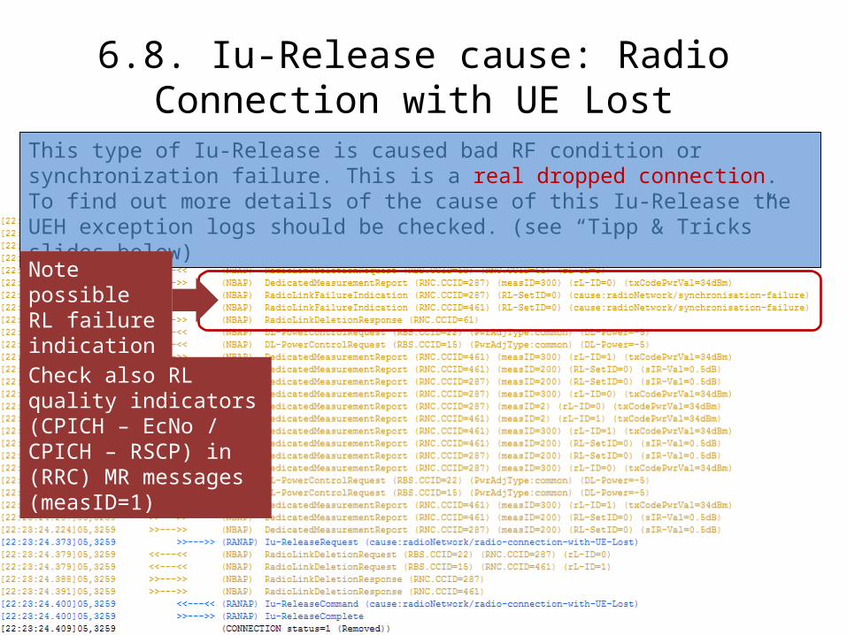
6.8. Iu-Release cause: Radio Connection with UE Lost
This type of Iu-Release is caused bad RF condition or synchronization failure. This is a real dropped connection. To find out more details of the cause of this Iu-Release the UEH exception logs should be checked. (see “Tipp & Tricks” slides below)
Note possible RL failure indications!
Check also RL quality indicators (CPICH – EcNo / CPICH – RSCP) in (RRC) MR messages (measID=1)

7. Call Failures
• Examples of Failures:
• CS –PS –HS calls
(setup/ASU/CM/SHO/HH/IRAT-CC/Thrpt)

7. RL Lost due to Synchronisation Failure
In case of Lost RL due to synchronisation failure the RL can be identified by going UP to the event of the RL addition/reconfig. for the Radio Link´s RNC.CCID

7. UE Lost due to No Response to ASU
AAL2 Setup Failure
ASU Timer expired
Iu-Release: UE lost
RL synch. Failure
Large delay of sending ASU complete
Large delay of sending ASU complete
No ASU Compl. Received before Timer expired

7. UE lost due ASU Complete not received

7. RL Deletion Failure due to AAL2 Failure
NBAP-RL Deletion Reqests
AAL2 Failure: RL is not deleted
Iu-Release: cause = om_intervention