ucla electrical engineering department ee215a tutorial.pdf · ucla electrical engineering...
TRANSCRIPT

UCLA Electrical Engineering Department EE215A
1
Cadence Tutorial
Long Kong
1.1: Tool-setup
1.2: Starting up Cadence 6
1.3: Build a differential pair
Tutorial 1.1: Tool-setup Go to SEASnet website:
http://www.seasnet.ucla.edu/UnixServers/eeapps
Follow instructions and install MobaXterm.
Once installed:
1. Start > All Programs > MobaXterm
2. Type the following to connect to eeapps:
ssh –X [email protected]
3. Type your password when it asks for it.
Download tool.zip from CCL website:
http://www.seas.ucla.edu/brweb/teaching.html
Unzip it and there are three files: 215a.scs, cds.lib and tool-setup
Create ee215a directory in your home directory:
UCLA Electrical Engineering Department EE215A
2
mkdir ee215a <-- create ee215a directory
cd ee215a <-- go to ee215a
pwd <-- find the current path
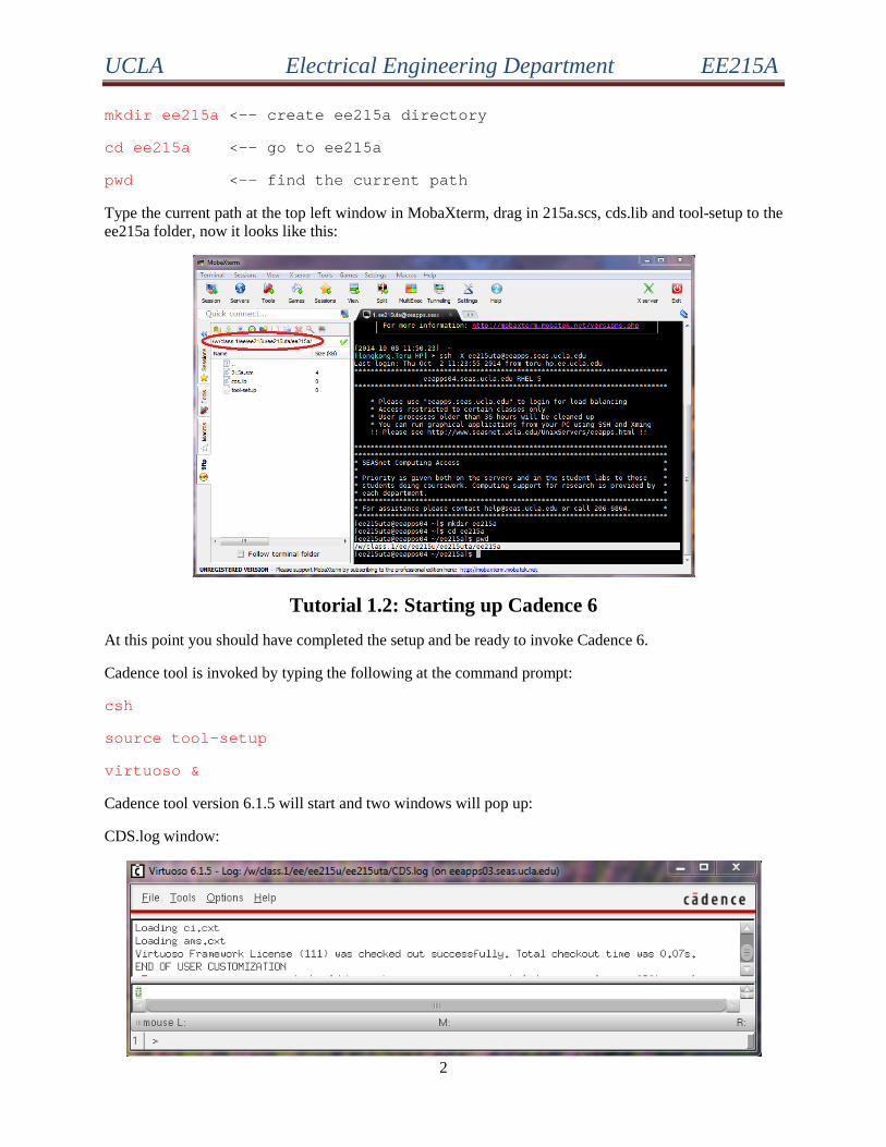
Type the current path at the top left window in MobaXterm, drag in 215a.scs, cds.lib and tool-setup to the ee215a folder, now it looks like this:
Tutorial 1.2: Starting up Cadence 6 At this point you should have completed the setup and be ready to invoke Cadence 6.
Cadence tool is invoked by typing the following at the command prompt:
csh
source tool-setup
virtuoso &
Cadence tool version 6.1.5 will start and two windows will pop up:
CDS.log window:
UCLA Electrical Engineering Department EE215A
3
Tool news and info window:
Close the tool news and info window by selecting File > Close.
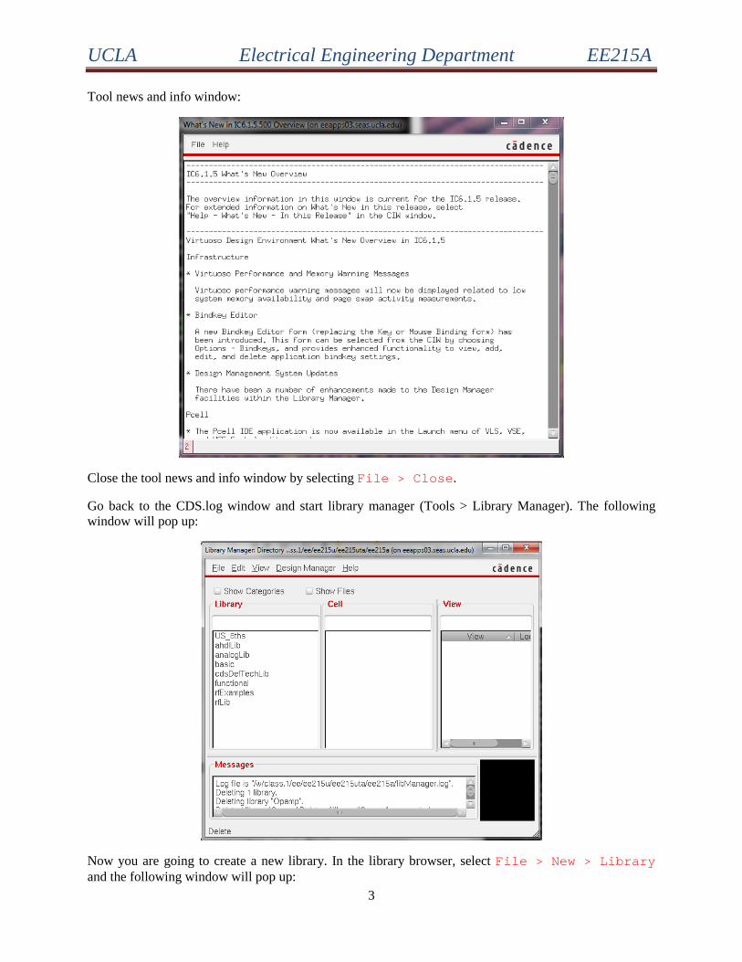
Go back to the CDS.log window and start library manager (Tools > Library Manager). The following window will pop up:
Now you are going to create a new library. In the library browser, select File > New > Library and the following window will pop up:

UCLA Electrical Engineering Department EE215A
4
Type ee215a in the name field.
Click OK.
You should now see the “Technology File for New Library”
Select Attach to an existing technology library option.
Click OK.
“Attach Library to Technology Library” window will pop up:
Select analogLib from the Technology Library menu.

UCLA Electrical Engineering Department EE215A
5
Click OK.
Next, you will see ee215a in the list of libraries in the Library Manager window.
Tutorial 1.3: Build a differential pair
In the library browser, click to select ee215a library and then click File > New > Cellview… to create schematic view for the new cell.
Type Diffpair in the Cell Name field as shown.
Click OK.
After you click OK, Virtouso Schematic Editing window will pop up.

UCLA Electrical Engineering Department EE215A
6
Important note: When you print any schematic from screenshot, remember to set the background color to white in MS office. For example, you can set transparent color of the above window to be white:

UCLA Electrical Engineering Department EE215A
7
Next, we will create simple schematic consisting of three NMOSs, two loading resistors, and a few bias voltage sources. To create an instance, you can click Create > Instance in the Virtuoso schematic editor or simply use shortcut key ‘i’. The following dialog will appear:
Click Browse to select a library component.
Another window will show up:
Choose analogLib library, nmos4 cell, symbol view. (note: while you are doing this, the Add instance window is getting updated as well).
Click Close and point your mouse cursor over the Virtuoso editing window.
Left click to place the instance into a desired location. As you move the mouse away, you will see a contour for another instance (shown in yellow); press ‘Esc’ key to exit from Add Instance mode and the yellow symbol will disappear.

UCLA Electrical Engineering Department EE215A
8
Now, add instance of another NMOS device (press ‘i’) and click Sideways,
Place it to the desired location.

UCLA Electrical Engineering Department EE215A
9
Now we can adjust the size of the transistors by editing instance properties. Left click on the NMOS to select the component. Then, press ‘q’ to modify its properties. Set Model name to nch (pch for PMOS), Width to 26um, Length to 180nm, S/D diffusion area to 1.56e-11 and periphery to 53.2u (calculation provided in handout).

UCLA Electrical Engineering Department EE215A
10
Click OK and repeat this for another NMOS. Add one more NMOS as the tail current source and set the W/L to 14um/180nm.
Next, add loading resistor to the schematic (cell res from analogLib library), then instantiate DC voltage source (cell vdc from analogLib library) to bias the transistors. After that, add two sine waves as the differential inputs (cell vsin from analogLib) . Set Amplitude to 1mV, Initial phase to 0 and Frequency to 1MHz. The other sine wave has the same amplitude and frequency but with an initial phase of 180.
The schematic should look like this (use Create > Wire menu or simply press ‘w’ key to enter wiring mode / ‘Esc’ to exit):

UCLA Electrical Engineering Department EE215A
11
It is a good practice to periodically save your work by clicking on Check and Save button. You can also save your work from the drop-down menu File > Save (or File > Check and Save).
Invoke simulation environment by choosing Launch > ADE L from the Virtuoso schematic editor window. Note: If you are asked to check the license for “Analog_Design_Environment_XL”, choose Yes or Always. The Analog Design Environment window will pop up:
The first step is to setup simulation environment, including models, input sources, type of analysis etc.

UCLA Electrical Engineering Department EE215A
12
Setup > Model Libraries and set the Model Library File to 215a.scs inside the ee215a folder and set Section to mos as shown below.
Click OK and go to Analyses > Choose, following entry form will show up.
Specify the Stop Time to 10u and click OK.
Your Analog Design Environment window should now look like this:

UCLA Electrical Engineering Department EE215A
13
Start the simulation by clicking on “Netlist and Run”. Then the output log window pops up:
UCLA Electrical Engineering Department EE215A
14
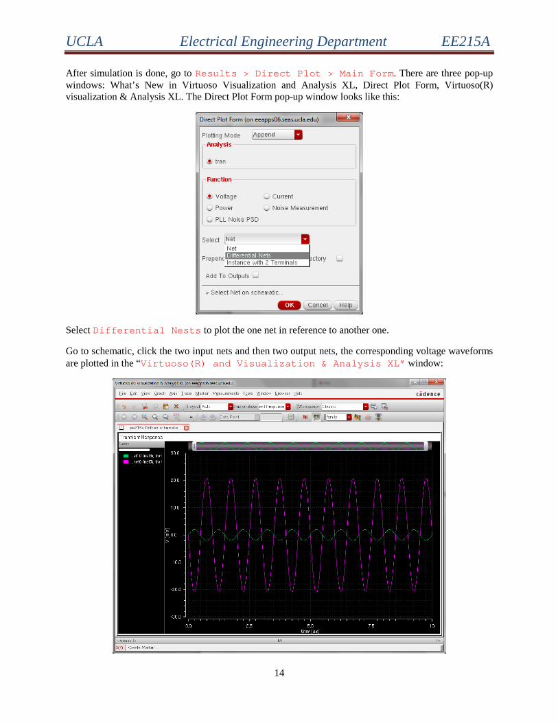
After simulation is done, go to Results > Direct Plot > Main Form. There are three pop-up windows: What’s New in Virtuoso Visualization and Analysis XL, Direct Plot Form, Virtuoso(R) visualization & Analysis XL. The Direct Plot Form pop-up window looks like this:
Select Differential Nests to plot the one net in reference to another one.
Go to schematic, click the two input nets and then two output nets, the corresponding voltage waveforms are plotted in the “Virtuoso(R) and Visualization & Analysis XL” window:

UCLA Electrical Engineering Department EE215A
15
To change the background color, go to Graph > Properties, the following window shows up:
Change the color to white and click OK. The “Virtuoso(R) and Visualization & Analysis XL” window now looks like this:
Now you are able to monitor more voltage and current waveforms at other nodes and can build circuit on your own.