uart
DESCRIPTION
MPS430F5336 UCS (Uart Module)TRANSCRIPT
Chapter Excerpt from SLAU208
Chapter 1SLAU410B–August 2012–Revised February 2013
Universal Serial Communication Interface – UART Mode
NOTE: This chapter is an excerpt from the MSP430x5xx and MSP430x6xx Family User's Guide.The most recent version of the full user's guide is available athttp://www.ti.com/lit/pdf/slau208.
The universal serial communication interface (USCI) supports multiple serial communication modes withone hardware module. This chapter discusses the operation of the asynchronous UART mode.
Topic ........................................................................................................................... Page
1.1 Universal Serial Communication Interface (USCI) Overview ..................................... 21.2 USCI Introduction – UART Mode ........................................................................... 31.3 USCI Operation – UART Mode .............................................................................. 51.4 USCI_A UART Mode Registers ............................................................................ 21
1SLAU410B–August 2012–Revised February 2013 Universal Serial Communication Interface – UART ModeSubmit Documentation Feedback
Copyright © 2012–2013, Texas Instruments Incorporated

Chapter Excerpt from SLAU208
Universal Serial Communication Interface (USCI) Overview www.ti.com
1.1 Universal Serial Communication Interface (USCI) Overview
The USCI modules support multiple serial communication modes. Different USCI modules supportdifferent modes. Each different USCI module is named with a different letter. For example, USCI_A isdifferent from USCI_B, etc. If more than one identical USCI module is implemented on one device, thosemodules are named with incrementing numbers. For example, if one device has two USCI_A modules,they are named USCI_A0 and USCI_A1. See the device-specific data sheet to determine which USCImodules, if any, are implemented on which devices.
USCI_Ax modules support:
• UART mode
• Pulse shaping for IrDA communications
• Automatic baud-rate detection for LIN communications
• SPI mode
USCI_Bx modules support:
• I2C mode
• SPI mode
2 Universal Serial Communication Interface – UART Mode SLAU410B–August 2012–Revised February 2013Submit Documentation Feedback
Copyright © 2012–2013, Texas Instruments Incorporated

Chapter Excerpt from SLAU208
www.ti.com USCI Introduction – UART Mode
1.2 USCI Introduction – UART Mode
In asynchronous mode, the USCI_Ax modules connect the device to an external system via two externalpins, UCAxRXD and UCAxTXD. UART mode is selected when the UCSYNC bit is cleared.
UART mode features include:
• 7- or 8-bit data with odd, even, or non-parity
• Independent transmit and receive shift registers
• Separate transmit and receive buffer registers
• LSB-first or MSB-first data transmit and receive
• Built-in idle-line and address-bit communication protocols for multiprocessor systems
• Receiver start-edge detection for auto wake up from LPMx modes (wake up from LPMx.5 is notsupported)
• Programmable baud rate with modulation for fractional baud-rate support
• Status flags for error detection and suppression
• Status flags for address detection
• Independent interrupt capability for receive and transmit
3SLAU410B–August 2012–Revised February 2013 Universal Serial Communication Interface – UART ModeSubmit Documentation Feedback
Copyright © 2012–2013, Texas Instruments Incorporated

Modulator
ACLK
SMCLK
SMCLK
00
01
10
11
UCSSELx
UCAxCLK
Prescaler/Divider
Receive Baudrate Generator
UC0BRx
16
UCBRFx
4
UCBRSx
3
UCOS16
UCRXERRError Flags
Set Flags
UCPE
UCFE
UCOE
UCABEN
Receive Shift Register
Receive Buffer UCAxRXBUF
Receive State Machine
1
0
UCIREN
UCPEN UCPAR UCMSB UC7BIT
UCDORMUCMODEx
2
UCSPB
Set UCBRK
Set UCADDR /UCIDLE
0
1
UCLISTEN
UCAxRXD
1
0
UCIRRXPL
IrDA Decoder
UCIRRXFEUCIRRXFLx
6
Transmit Buffer UCAxTXBUF
Transmit State Machine
UCTXADDR
UCTXBRK
Transmit Shift Register
UCPEN UCPAR UCMSB UC7BIT UCIREN
UCIRTXPLx
6
0
1
IrDA EncoderUCAxTXD
Transmit Clock
Receive Clock
BRCLK
UCMODEx
2
UCSPB
UCRXEIE
UCRXBRKIE
Set UCRXIFG
Set UCTXIFG
Set RXIFG
Chapter Excerpt from SLAU208
USCI Introduction – UART Mode www.ti.com
Figure 1-1 shows the USCI_Ax when configured for UART mode.
Figure 1-1. USCI_Ax Block Diagram – UART Mode (UCSYNC = 0)
4 Universal Serial Communication Interface – UART Mode SLAU410B–August 2012–Revised February 2013Submit Documentation Feedback
Copyright © 2012–2013, Texas Instruments Incorporated

[Parity Bit, UCPEN = 1]
[Address Bit, UCMODEx = 10]
Mark
SpaceD0 D6 D7 AD PA SP SP
[Optional Bit, Condition]
[2nd Stop Bit, UCSPB = 1]
[8th Data Bit, UC7BIT = 0]
ST
Chapter Excerpt from SLAU208
www.ti.com USCI Operation – UART Mode
1.3 USCI Operation – UART Mode
In UART mode, the USCI transmits and receives characters at a bit rate asynchronous to another device.Timing for each character is based on the selected baud rate of the USCI. The transmit and receivefunctions use the same baud-rate frequency.
1.3.1 USCI Initialization and Reset
The USCI is reset by a PUC or by setting the UCSWRST bit. After a PUC, the UCSWRST bit isautomatically set, keeping the USCI in a reset condition. When set, the UCSWRST bit resets the UCRXIE,UCTXIE, UCRXIFG, UCRXERR, UCBRK, UCPE, UCOE, UCFE, UCSTOE, and UCBTOE bits, and setsthe UCTXIFG bit. Clearing UCSWRST releases the USCI for operation.
To avoid unpredictable behavior, configure or reconfigure the USCI_A module only when UCSWRST isset.
NOTE: Initializing or reconfiguring the USCI module
The recommended USCI initialization/reconfiguration process is:1. Set UCSWRST (BIS.B
#UCSWRST,&UCAxCTL1).
2. Initialize all USCI registers with UCSWRST = 1 (including UCAxCTL1).3. Configure ports.4. Clear UCSWRST via software (BIC.B
#UCSWRST,&UCAxCTL1).
5. Enable interrupts (optional) via UCRXIE and/or UCTXIE.
1.3.2 Character Format
The UART character format (see Figure 1-2) consists of a start bit, seven or eight data bits, aneven/odd/no parity bit, an address bit (address-bit mode), and one or two stop bits. The UCMSB bitcontrols the direction of the transfer and selects LSB or MSB first. LSB first is typically required for UARTcommunication.
Figure 1-2. Character Format
1.3.3 Asynchronous Communication Format
When two devices communicate asynchronously, no multiprocessor format is required for the protocol.When three or more devices communicate, the USCI supports the idle-line and address-bit multiprocessorcommunication formats.
1.3.3.1 Idle-Line Multiprocessor Format
When UCMODEx = 01, the idle-line multiprocessor format is selected. Blocks of data are separated by anidle time on the transmit or receive lines (see Figure 1-3). An idle receive line is detected when ten ormore continuous ones (marks) are received after the one or two stop bits of a character. The baud-rategenerator is switched off after reception of an idle line until the next start edge is detected. When an idleline is detected, the UCIDLE bit is set.
5SLAU410B–August 2012–Revised February 2013 Universal Serial Communication Interface – UART ModeSubmit Documentation Feedback
Copyright © 2012–2013, Texas Instruments Incorporated

Chapter Excerpt from SLAU208
USCI Operation – UART Mode www.ti.com
The first character received after an idle period is an address character. The UCIDLE bit is used as anaddress tag for each block of characters. In idle-line multiprocessor format, this bit is set when a receivedcharacter is an address.
Figure 1-3. Idle-Line Format
The UCDORM bit is used to control data reception in the idle-line multiprocessor format. WhenUCDORM = 1, all non-address characters are assembled but not transferred into the UCAxRXBUF, andinterrupts are not generated. When an address character is received, the character is transferred intoUCAxRXBUF, UCRXIFG is set, and any applicable error flag is set when UCRXEIE = 1. When UCRXEIE= 0 and an address character is received but has a framing error or parity error, the character is nottransferred into UCAxRXBUF and UCRXIFG is not set.
If an address is received, user software can validate the address and must reset UCDORM to continuereceiving data. If UCDORM remains set, only address characters are received. When UCDORM is clearedduring the reception of a character, the receive interrupt flag is set after the reception completed. TheUCDORM bit is not modified by the USCI hardware automatically.
For address transmission in idle-line multiprocessor format, a precise idle period can be generated by theUSCI to generate address character identifiers on UCAxTXD. The double-buffered UCTXADDR flagindicates if the next character loaded into UCAxTXBUF is preceded by an idle line of 11 bits. UCTXADDRis automatically cleared when the start bit is generated.
1.3.3.1.1 Transmitting an Idle Frame
The following procedure sends out an idle frame to indicate an address character followed by associateddata:
1. Set UCTXADDR, then write the address character to UCAxTXBUF. UCAxTXBUF must be ready fornew data (UCTXIFG = 1).
This generates an idle period of exactly 11 bits followed by the address character. UCTXADDR is resetautomatically when the address character is transferred from UCAxTXBUF into the shift register.
2. Write desired data characters to UCAxTXBUF. UCAxTXBUF must be ready for new data (UCTXIFG =1).
The data written to UCAxTXBUF is transferred to the shift register and transmitted as soon as the shiftregister is ready for new data.
The idle-line time must not be exceeded between address and data transmission or between datatransmissions. Otherwise, the transmitted data is misinterpreted as an address.
6 Universal Serial Communication Interface – UART Mode SLAU410B–August 2012–Revised February 2013Submit Documentation Feedback
Copyright © 2012–2013, Texas Instruments Incorporated

ST Address SP ST Data SP ST Data SP
Blocks of
Characters
Idle Periods of No Significance
UCAxTXD/UCAxRXD
Expanded
UCAxTXD/UCAxRXD
First Character Within Block
Is an Address. AD Bit Is 1
AD Bit Is 0 for
Data Within Block. Idle Time Is of No Significance
UCAxTXD/UCAxRXD 1 0 0
Chapter Excerpt from SLAU208
www.ti.com USCI Operation – UART Mode
1.3.3.2 Address-Bit Multiprocessor Format
When UCMODEx = 10, the address-bit multiprocessor format is selected. Each processed charactercontains an extra bit used as an address indicator (see Figure 1-4). The first character in a block ofcharacters carries a set address bit that indicates that the character is an address. The USCI UCADDR bitis set when a received character has its address bit set and is transferred to UCAxRXBUF.
The UCDORM bit is used to control data reception in the address-bit multiprocessor format. WhenUCDORM is set, data characters with address bit = 0 are assembled by the receiver but are nottransferred to UCAxRXBUF and no interrupts are generated. When a character containing a set addressbit is received, the character is transferred into UCAxRXBUF, UCRXIFG is set, and any applicable errorflag is set when UCRXEIE = 1. When UCRXEIE = 0 and a character containing a set address bit isreceived but has a framing error or parity error, the character is not transferred into UCAxRXBUF andUCRXIFG is not set.
If an address is received, user software can validate the address and must reset UCDORM to continuereceiving data. If UCDORM remains set, only address characters with address bit = 1 are received. TheUCDORM bit is not modified by the USCI hardware automatically.
When UCDORM = 0, all received characters set the receive interrupt flag UCRXIFG. If UCDORM iscleared during the reception of a character, the receive interrupt flag is set after the reception iscompleted.
For address transmission in address-bit multiprocessor mode, the address bit of a character is controlledby the UCTXADDR bit. The value of the UCTXADDR bit is loaded into the address bit of the charactertransferred from UCAxTXBUF to the transmit shift register. UCTXADDR is automatically cleared when thestart bit is generated.
Figure 1-4. Address-Bit Multiprocessor Format
1.3.3.2.1 Break Reception and Generation
When UCMODEx = 00, 01, or 10, the receiver detects a break when all data, parity, and stop bits are low,regardless of the parity, address mode, or other character settings. When a break is detected, the UCBRKbit is set. If the break interrupt enable bit (UCBRKIE) is set, the receive interrupt flag UCRXIFG is also set.In this case, the value in UCAxRXBUF is 0h, because all data bits were zero.
To transmit a break, set the UCTXBRK bit, then write 0h to UCAxTXBUF. UCAxTXBUF must be ready fornew data (UCTXIFG = 1). This generates a break with all bits low. UCTXBRK is automatically clearedwhen the start bit is generated.
7SLAU410B–August 2012–Revised February 2013 Universal Serial Communication Interface – UART ModeSubmit Documentation Feedback
Copyright © 2012–2013, Texas Instruments Incorporated

Synch
Start
Bit
Stop
Bit0 1 2 3 4 5 6 7
8 Bit Times
Break Delimiter Synch
Chapter Excerpt from SLAU208
USCI Operation – UART Mode www.ti.com
1.3.4 Automatic Baud-Rate Detection
When UCMODEx = 11, UART mode with automatic baud-rate detection is selected. For automatic baud-rate detection, a data frame is preceded by a synchronization sequence that consists of a break and asynch field. A break is detected when 11 or more continuous zeros (spaces) are received. If the length ofthe break exceeds 21 bit times the break timeout error flag UCBTOE is set. The USCI can not transmitdata while receiving the break/sync field. The synch field follows the break as shown in Figure 1-5.
Figure 1-5. Auto Baud-Rate Detection – Break/Synch Sequence
For LIN conformance, the character format should be set to eight data bits, LSB first, no parity, and onestop bit. No address bit is available.
The synch field consists of the data 055h inside a byte field (see Figure 1-6). The synchronization isbased on the time measurement between the first falling edge and the last falling edge of the pattern. Thetransmit baud-rate generator is used for the measurement if automatic baud-rate detection is enabled bysetting UCABDEN. Otherwise, the pattern is received but not measured. The result of the measurement istransferred into the baud-rate control registers (UCAxBR0, UCAxBR1, and UCAxMCTL). If the length ofthe synch field exceeds the measurable time, the synch timeout error flag UCSTOE is set.
Figure 1-6. Auto Baud-Rate Detection – Synch Field
The UCDORM bit is used to control data reception in this mode. When UCDORM is set, all characters arereceived but not transferred into the UCAxRXBUF, and interrupts are not generated. When a break/synchfield is detected, the UCBRK flag is set. The character following the break/synch field is transferred intoUCAxRXBUF and the UCRXIFG interrupt flag is set. Any applicable error flag is also set. If the UCBRKIEbit is set, reception of the break/synch sets the UCRXIFG. The UCBRK bit is reset by user software or byreading the receive buffer UCAxRXBUF.
When a break/synch field is received, user software must reset UCDORM to continue receiving data. IfUCDORM remains set, only the character after the next reception of a break/synch field is received. TheUCDORM bit is not modified by the USCI hardware automatically.
When UCDORM = 0, all received characters set the receive interrupt flag UCRXIFG. If UCDORM iscleared during the reception of a character, the receive interrupt flag is set after the reception is complete.
The counter used to detect the baud rate is limited to 07FFFh (32767) counts. This means the minimumbaud rate detectable is 488 baud in oversampling mode and 30 baud in low-frequency mode.
The automatic baud-rate detection mode can be used in a full-duplex communication system with somerestrictions. The USCI can not transmit data while receiving the break/sync field and, if a 0h byte withframing error is received, any data transmitted during this time gets corrupted. The latter case can bediscovered by checking the received data and the UCFE bit.
8 Universal Serial Communication Interface – UART Mode SLAU410B–August 2012–Revised February 2013Submit Documentation Feedback
Copyright © 2012–2013, Texas Instruments Incorporated
UART
Start
Bit Data Bits
Stop
Bit
IrDA
Chapter Excerpt from SLAU208
www.ti.com USCI Operation – UART Mode
1.3.4.1 Transmitting a Break/Synch Field
The following procedure transmits a break/synch field:
1. Set UCTXBRK with UMODEx = 11.
2. Write 055h to UCAxTXBUF. UCAxTXBUF must be ready for new data (UCTXIFG = 1).
This generates a break field of 13 bits followed by a break delimiter and the synch character. Thelength of the break delimiter is controlled with the UCDELIMx bits. UCTXBRK is reset automaticallywhen the synch character is transferred from UCAxTXBUF into the shift register.
3. Write desired data characters to UCAxTXBUF. UCAxTXBUF must be ready for new data(UCTXIFG = 1).
The data written to UCAxTXBUF is transferred to the shift register and transmitted as soon as the shiftregister is ready for new data.
1.3.5 IrDA Encoding and Decoding
When UCIREN is set, the IrDA encoder and decoder are enabled and provide hardware bit shaping forIrDA communication.
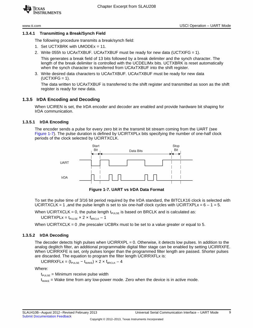
1.3.5.1 IrDA Encoding
The encoder sends a pulse for every zero bit in the transmit bit stream coming from the UART (seeFigure 1-7). The pulse duration is defined by UCIRTXPLx bits specifying the number of one-half clockperiods of the clock selected by UCIRTXCLK.
Figure 1-7. UART vs IrDA Data Format
To set the pulse time of 3/16 bit period required by the IrDA standard, the BITCLK16 clock is selected withUCIRTXCLK = 1 ,and the pulse length is set to six one-half clock cycles with UCIRTXPLx = 6 – 1 = 5.
When UCIRTXCLK = 0, the pulse length tPULSE is based on BRCLK and is calculated as:UCIRTXPLx = tPULSE × 2 × fBRCLK – 1
When UCIRTXCLK = 0 ,the prescaler UCBRx must to be set to a value greater or equal to 5.
1.3.5.2 IrDA Decoding
The decoder detects high pulses when UCIRRXPL = 0. Otherwise, it detects low pulses. In addition to theanalog deglitch filter, an additional programmable digital filter stage can be enabled by setting UCIRRXFE.When UCIRRXFE is set, only pulses longer than the programmed filter length are passed. Shorter pulsesare discarded. The equation to program the filter length UCIRRXFLx is:
UCIRRXFLx = (tPULSE − tWAKE) × 2 × fBRCLK – 4
Where:tPULSE = Minimum receive pulse widthtWAKE = Wake time from any low-power mode. Zero when the device is in active mode.
9SLAU410B–August 2012–Revised February 2013 Universal Serial Communication Interface – UART ModeSubmit Documentation Feedback
Copyright © 2012–2013, Texas Instruments Incorporated

Chapter Excerpt from SLAU208
USCI Operation – UART Mode www.ti.com
1.3.6 Automatic Error Detection
Glitch suppression prevents the USCI from being accidentally started. Any pulse on UCAxRXD shorterthan the deglitch time tt (approximately 150 ns) is ignored (see the device-specific data sheet forparameters).
When a low period on UCAxRXD exceeds tt, a majority vote is taken for the start bit. If the majority votefails to detect a valid start bit, the USCI halts character reception and waits for the next low period onUCAxRXD. The majority vote is also used for each bit in a character to prevent bit errors.
The USCI module automatically detects framing errors, parity errors, overrun errors, and break conditionswhen receiving characters. The bits UCFE, UCPE, UCOE, and UCBRK are set when their respectivecondition is detected. When the error flags UCFE, UCPE, or UCOE are set, UCRXERR is also set. Theerror conditions are described in Table 1-1.
Table 1-1. Receive Error Conditions
Error Condition Error Flag Description
Framing error UCFE A framing error occurs when a low stop bit is detected. When two stop bits are used, bothstop bits are checked for framing error. When a framing error is detected, the UCFE bit is set.
Parity error UCPE A parity error is a mismatch between the number of 1s in a character and the value of theparity bit. When an address bit is included in the character, it is included in the paritycalculation. When a parity error is detected, the UCPE bit is set.
Receive overrun UCOE An overrun error occurs when a character is loaded into UCAxRXBUF before the priorcharacter has been read. When an overrun occurs, the UCOE bit is set.
Break condition UCBRK When not using automatic baud-rate detection, a break is detected when all data, parity, andstop bits are low. When a break condition is detected, the UCBRK bit is set. A break conditioncan also set the interrupt flag UCRXIFG if the break interrupt enable UCBRKIE bit is set.
When UCRXEIE = 0 and a framing error or parity error is detected, no character is received intoUCAxRXBUF. When UCRXEIE = 1, characters are received into UCAxRXBUF and any applicable errorbit is set.
When any of the UCFE, UCPE, UCOE, UCBRK, or UCRXERR bit is set, the bit remains set until usersoftware resets it or UCAxRXBUF is read. UCOE must be reset by reading UCAxRXBUF. Otherwise, itdoes not function properly. To detect overflows reliably the following flow is recommended. After acharacter was received and UCAxRXIFG is set, first read UCAxSTAT to check the error flags including theoverflow flag UCOE. Read UCAxRXBUF next. This clears all error flags except UCOE, if UCAxRXBUFwas overwritten between the read access to UCAxSTAT and to UCAxRXBUF. Therefore, the UCOE flagshould be checked after reading UCAxRXBUF to detect this condition. Note that, in this case, theUCRXERR flag is not set.
10 Universal Serial Communication Interface – UART Mode SLAU410B–August 2012–Revised February 2013Submit Documentation Feedback
Copyright © 2012–2013, Texas Instruments Incorporated
URXS
Majority Vote Taken
tt
tt
UCAxRXD
URXS
Chapter Excerpt from SLAU208
www.ti.com USCI Operation – UART Mode
1.3.7 USCI Receive Enable
The USCI module is enabled by clearing the UCSWRST bit and the receiver is ready and in an idle state.The receive baud rate generator is in a ready state but is not clocked nor producing any clocks.
The falling edge of the start bit enables the baud rate generator and the UART state machine checks for avalid start bit. If no valid start bit is detected the UART state machine returns to its idle state and the baudrate generator is turned off again. If a valid start bit is detected, a character is received.
When the idle-line multiprocessor mode is selected with UCMODEx = 01 the UART state machine checksfor an idle line after receiving a character. If a start bit is detected another character is received. Otherwisethe UCIDLE flag is set after 10 ones are received and the UART state machine returns to its idle state andthe baud rate generator is turned off.
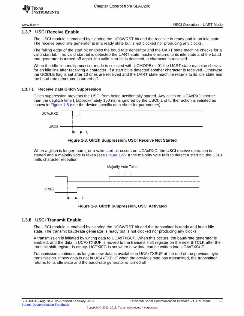
1.3.7.1 Receive Data Glitch Suppression
Glitch suppression prevents the USCI from being accidentally started. Any glitch on UCAxRXD shorterthan the deglitch time tt (approximately 150 ns) is ignored by the USCI, and further action is initiated asshown in Figure 1-8 (see the device-specific data sheet for parameters).
Figure 1-8. Glitch Suppression, USCI Receive Not Started
When a glitch is longer than tt, or a valid start bit occurs on UCAxRXD, the USCI receive operation isstarted and a majority vote is taken (see Figure 1-9). If the majority vote fails to detect a start bit, the USCIhalts character reception.
Figure 1-9. Glitch Suppression, USCI Activated
1.3.8 USCI Transmit Enable
The USCI module is enabled by clearing the UCSWRST bit and the transmitter is ready and in an idlestate. The transmit baud-rate generator is ready but is not clocked nor producing any clocks.
A transmission is initiated by writing data to UCAxTXBUF. When this occurs, the baud-rate generator isenabled, and the data in UCAxTXBUF is moved to the transmit shift register on the next BITCLK after thetransmit shift register is empty. UCTXIFG is set when new data can be written into UCAxTXBUF.
Transmission continues as long as new data is available in UCAxTXBUF at the end of the previous bytetransmission. If new data is not in UCAxTXBUF when the previous byte has transmitted, the transmitterreturns to its idle state and the baud-rate generator is turned off.
11SLAU410B–August 2012–Revised February 2013 Universal Serial Communication Interface – UART ModeSubmit Documentation Feedback
Copyright © 2012–2013, Texas Instruments Incorporated

N/2
Bit Start
BRCLK
Counter
BITCLK
N/2-1 N/2-21 N/2 N/2-1 1 N/2 N/2-1N/2-2
0 N/2 N/2-11
INT(N/2) + m(= 0)
INT(N/2) + m(= 1)
1 0 N/2
Bit Period
NEVEN: INT(N/2)
NODD: INT(N/2) + R(= 1)
m: corresponding modulation bit
R: Remainder from N/2 division
Majority Vote: (m= 0)
(m= 1)
Chapter Excerpt from SLAU208
USCI Operation – UART Mode www.ti.com
1.3.9 UART Baud-Rate Generation
The USCI baud-rate generator is capable of producing standard baud rates from nonstandard sourcefrequencies. It provides two modes of operation selected by the UCOS16 bit. The baud-rate is generateusing the BRCLK that can be sourced by the external clock UCAxCLK, or the internal clocks ACLK orSMCLK depending on the UCSSELx settings.
1.3.9.1 Low-Frequency Baud-Rate Generation
The low-frequency mode is selected when UCOS16 = 0. This mode allows generation of baud rates fromlow frequency clock sources (for example, 9600 baud from a 32768-Hz crystal). By using a lower inputfrequency, the power consumption of the module is reduced. Using this mode with higher frequencies andhigher prescaler settings causes the majority votes to be taken in an increasingly smaller window and,thus, decrease the benefit of the majority vote.
In low-frequency mode, the baud-rate generator uses one prescaler and one modulator to generate bitclock timing. This combination supports fractional divisors for baud-rate generation. In this mode, themaximum USCI baud rate is one-third the UART source clock frequency BRCLK.
Timing for each bit is shown in Figure 1-10. For each bit received, a majority vote is taken to determinethe bit value. These samples occur at the N/2 – 1/2, N/2, and N/2 + 1/2 BRCLK periods, where N is thenumber of BRCLKs per BITCLK.
Figure 1-10. BITCLK Baud-Rate Timing With UCOS16 = 0
Modulation is based on the UCBRSx setting (see Table 1-2). A 1 in the table indicates that m = 1 and thecorresponding BITCLK period is one BRCLK period longer than a BITCLK period with m = 0. Themodulation wraps around after eight bits but restarts with each new start bit.
Table 1-2. BITCLK Modulation Pattern
Bit 0UCBRSx Bit 1 Bit 2 Bit 3 Bit 4 Bit 5 Bit 6 Bit 7(Start Bit)
0 0 0 0 0 0 0 0 0
1 0 1 0 0 0 0 0 0
2 0 1 0 0 0 1 0 0
3 0 1 0 1 0 1 0 0
4 0 1 0 1 0 1 0 1
5 0 1 1 1 0 1 0 1
6 0 1 1 1 0 1 1 1
7 0 1 1 1 1 1 1 1
12 Universal Serial Communication Interface – UART Mode SLAU410B–August 2012–Revised February 2013Submit Documentation Feedback
Copyright © 2012–2013, Texas Instruments Incorporated

Chapter Excerpt from SLAU208
www.ti.com USCI Operation – UART Mode
1.3.9.2 Oversampling Baud-Rate Generation
The oversampling mode is selected when UCOS16 = 1. This mode supports sampling a UART bit streamwith higher input clock frequencies. This results in majority votes that are always 1/16 of a bit clock periodapart. This mode also easily supports IrDA pulses with a 3/16 bit time when the IrDA encoder and decoderare enabled.
This mode uses one prescaler and one modulator to generate the BITCLK16 clock that is 16 times fasterthan the BITCLK. An additional divider and modulator stage generates BITCLK from BITCLK16. Thiscombination supports fractional divisions of both BITCLK16 and BITCLK for baud-rate generation. In thismode, the maximum USCI baud rate is 1/16 the UART source clock frequency BRCLK. When UCBRx isset to 0 or 1, the first prescaler and modulator stage is bypassed and BRCLK is equal to BITCLK16 – inthis case, no modulation for the BITCLK16 is possible and, thus, the UCBRFx bits are ignored.
Modulation for BITCLK16 is based on the UCBRFx setting (see Table 1-3). A 1 in the table indicates thatthe corresponding BITCLK16 period is one BRCLK period longer than the periods m = 0. The modulationrestarts with each new bit timing.
Modulation for BITCLK is based on the UCBRSx setting (see Table 1-2) as previously described.
Table 1-3. BITCLK16 Modulation Pattern
No. of BITCLK16 Clocks After Last Falling BITCLK EdgeUCBRFx
0 1 2 3 4 5 6 7 8 9 10 11 12 13 14 15
00h 0 0 0 0 0 0 0 0 0 0 0 0 0 0 0 0
01h 0 1 0 0 0 0 0 0 0 0 0 0 0 0 0 0
02h 0 1 0 0 0 0 0 0 0 0 0 0 0 0 0 1
03h 0 1 1 0 0 0 0 0 0 0 0 0 0 0 0 1
04h 0 1 1 0 0 0 0 0 0 0 0 0 0 0 1 1
05h 0 1 1 1 0 0 0 0 0 0 0 0 0 0 1 1
06h 0 1 1 1 0 0 0 0 0 0 0 0 0 1 1 1
07h 0 1 1 1 1 0 0 0 0 0 0 0 0 1 1 1
08h 0 1 1 1 1 0 0 0 0 0 0 0 1 1 1 1
09h 0 1 1 1 1 1 0 0 0 0 0 0 1 1 1 1
0Ah 0 1 1 1 1 1 0 0 0 0 0 1 1 1 1 1
0Bh 0 1 1 1 1 1 1 0 0 0 0 1 1 1 1 1
0Ch 0 1 1 1 1 1 1 0 0 0 1 1 1 1 1 1
0Dh 0 1 1 1 1 1 1 1 0 0 1 1 1 1 1 1
0Eh 0 1 1 1 1 1 1 1 0 1 1 1 1 1 1 1
0Fh 0 1 1 1 1 1 1 1 1 1 1 1 1 1 1 1
13SLAU410B–August 2012–Revised February 2013 Universal Serial Communication Interface – UART ModeSubmit Documentation Feedback
Copyright © 2012–2013, Texas Instruments Incorporated

mUCBR xF [j]15
j = 0S
T [i] =bit,TX
1fBRCLK
(((16 + m [i]) × UCBRx + [j]UCBRSx UCBR xm FS15
j = 0
Chapter Excerpt from SLAU208
USCI Operation – UART Mode www.ti.com
1.3.10 Setting a Baud Rate
For a given BRCLK clock source, the baud rate used determines the required division factor N:N = fBRCLK/Baudrate
The division factor N is often a noninteger value, thus, at least one divider and one modulator stage isused to meet the factor as closely as possible.
If N is equal or greater than 16, the oversampling baud-rate generation mode can be chosen by settingUCOS16.
1.3.10.1 Low-Frequency Baud-Rate Mode Setting
In low-frequency mode, the integer portion of the divisor is realized by the prescaler:UCBRx = INT(N)
and the fractional portion is realized by the modulator with the following nominal formula:UCBRSx = round[( N – INT(N)) × 8]
Incrementing or decrementing the UCBRSx setting by one count may give a lower maximum bit error forany given bit. To determine if this is the case, a detailed error calculation must be performed for each bitfor each UCBRSx setting.
1.3.10.2 Oversampling Baud-Rate Mode Setting
In the oversampling mode, the prescaler is set to:UCBRx = INT(N/16)
and the first stage modulator is set to:UCBRFx = round([(N/16) – INT(N/16)] × 16)
When greater accuracy is required, the UCBRSx modulator can also be implemented with values from 0to 7. To find the setting that gives the lowest maximum bit error rate for any given bit, a detailed errorcalculation must be performed for all settings of UCBRSx from 0 to 7 with the initial UCBRFx setting, andwith the UCBRFx setting incremented and decremented by one.
1.3.11 Transmit Bit Timing
The timing for each character is the sum of the individual bit timings. Using the modulation features of thebaud-rate generator reduces the cumulative bit error. The individual bit error can be calculated using thefollowing steps.
1.3.11.1 Low-Frequency Baud-Rate Mode Bit Timing
In low-frequency mode, calculate the length of bit i Tbit,TX[i] based on the UCBRx and UCBRSx settings:Tbit,TX[i] = (1/fBRCLK)(UCBRx + mUCBRSx[i])
Where:mUCBRSx[i] = Modulation of bit i from Table 1-2
1.3.11.2 Oversampling Baud-Rate Mode Bit Timing
In oversampling baud-rate mode, calculate the length of bit i Tbit,TX[i] based on the baud-rate generatorUCBRx, UCBRFx and UCBRSx settings:
Where:
= Sum of ones from the corresponding row in Table 1-3mUCBRSx[i] = Modulation of bit i from Table 1-2
14 Universal Serial Communication Interface – UART Mode SLAU410B–August 2012–Revised February 2013Submit Documentation Feedback
Copyright © 2012–2013, Texas Instruments Incorporated

T [j] +bit,RX
i – 1
j = 0S
1fBRCLK
t [i] = t +bit,RX SYNC INT(½UCBRx) + m [i]UCBRSx( (
1 2 3 4 5 6
0i
t0tideal
7 8
1 2
9 10 11 12 13 14 1 2 3 4 5 6 7 8 9 10 11 12 13 14 1 2 3 4 5 6 7
ST D0 D1
D0 D1ST
Synchronization Error ± 0.5x BRCLK
Majority Vote Taken Majority Vote Taken Majority Vote Taken
BRCLK
UCAxRXD
RXD synch.
tactual
Sample
RXD synch.
t0
t1
t1 t2
Tbit,TX[j]i
j = 0STbit,TX[i] =
Chapter Excerpt from SLAU208
www.ti.com USCI Operation – UART Mode
This results in an end-of-bit time tbit,TX[i] equal to the sum of all previous and the current bit times:
To calculate bit error, this time is compared to the ideal bit time tbit,ideal,TX[i]:tbit,ideal,TX[i] = (1/Baudrate)(i + 1)
This results in an error normalized to one ideal bit time (1/baudrate):ErrorTX[i] = (tbit,TX[i] – tbit,ideal,TX[i]) × Baudrate × 100%
1.3.12 Receive Bit Timing
Receive timing error consists of two error sources. The first is the bit-to-bit timing error similar to thetransmit bit timing error. The second is the error between a start edge occurring and the start edge beingaccepted by the USCI module. Figure 1-11 shows the asynchronous timing errors between data on theUCAxRXD pin and the internal baud-rate clock. This results in an additional synchronization error. Thesynchronization error tSYNC is between –0.5 BRCLKs and +0.5 RCLKs, independent of the selected baud-rate generation mode.
Figure 1-11. Receive Error
The ideal sampling time tbit,ideal,RX[i] is in the middle of a bit period:tbit,ideal,RX[i] = (1/Baudrate)(i + 0.5)
The real sampling time, tbit,RX[i], is equal to the sum of all previous bits according to the formulas shown inthe transmit timing section, plus one-half BITCLK for the current bit i, plus the synchronization error tSYNC.
This results in the following tbit,RX[i] for the low-frequency baud-rate mode:
Where:Tbit,RX[i] = (1/fBRCLK)(UCBRx + mUCBRSx[i])mUCBRSx[i] = Modulation of bit i from Table 1-2
15SLAU410B–August 2012–Revised February 2013 Universal Serial Communication Interface – UART ModeSubmit Documentation Feedback
Copyright © 2012–2013, Texas Instruments Incorporated
m [j]UCBRFx
7 + m [i]UCBRSx
j = 0S
(16 + m [i]) × UCBRx +UCBRSxT [i] =bit,RX
1fBRCLK
( (m [j]UCBRFx
15
j = 0S
t [i] = t +bit,RX SYNC (8 + m [i]) × UCBRx +UCBRSxT [j] +bit,RX
i – 1
j = 0S
1fBRCLK
( (m [j]UCBRFx
7 + m [i]UCBRSx
j = 0S
Chapter Excerpt from SLAU208
USCI Operation – UART Mode www.ti.com
For the oversampling baud-rate mode, the sampling time tbit,RX[i] of bit i is calculated by:
Where:
= Sum of ones from columns 0 to (7 + mUCBRSx[i]) from the corresponding row in Table 1-3.mUCBRSx[i] = Modulation of bit i from Table 1-2
This results in an error normalized to one ideal bit time (1/baudrate) according to the following formula:ErrorRX[i] = (tbit,RX[i] – tbit,ideal,RX[i]) × Baudrate × 100%
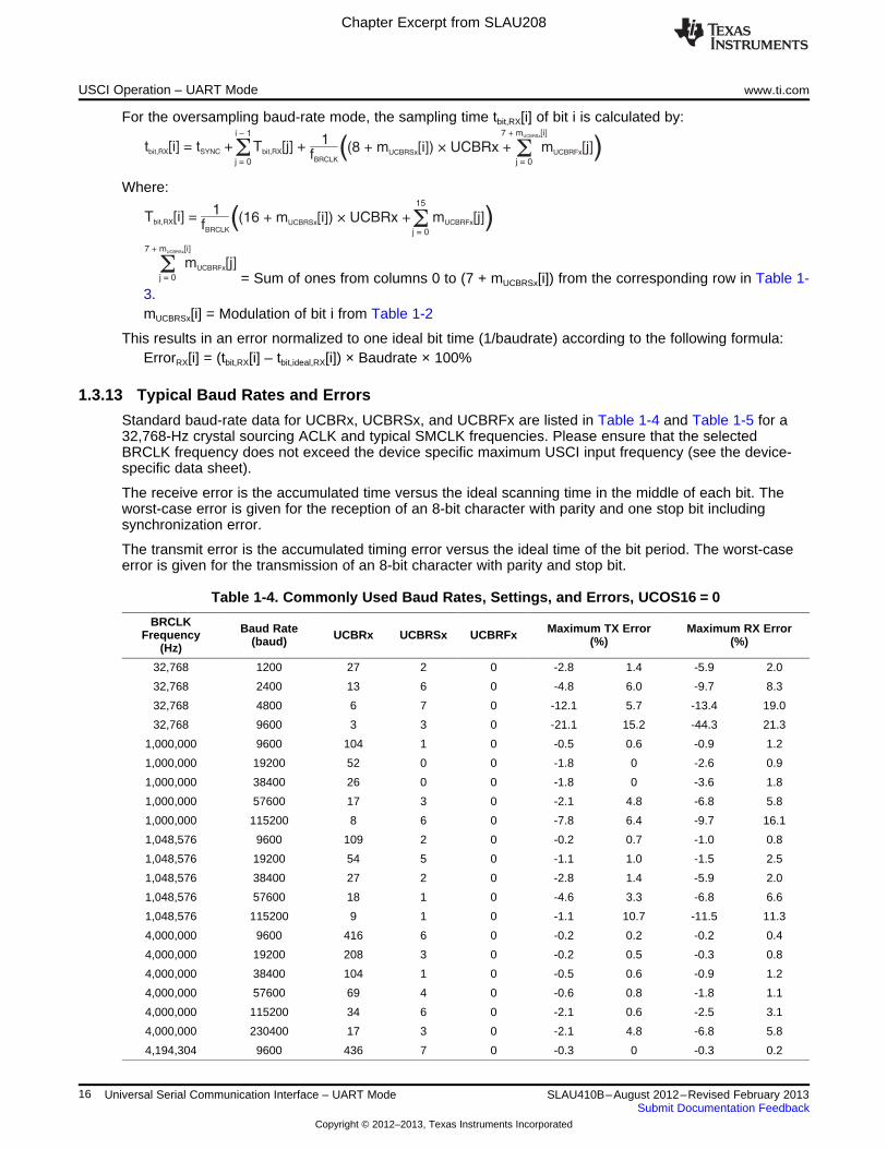
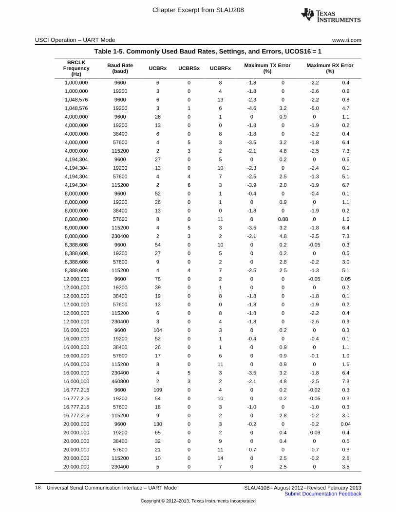
1.3.13 Typical Baud Rates and Errors
Standard baud-rate data for UCBRx, UCBRSx, and UCBRFx are listed in Table 1-4 and Table 1-5 for a32,768-Hz crystal sourcing ACLK and typical SMCLK frequencies. Please ensure that the selectedBRCLK frequency does not exceed the device specific maximum USCI input frequency (see the device-specific data sheet).
The receive error is the accumulated time versus the ideal scanning time in the middle of each bit. Theworst-case error is given for the reception of an 8-bit character with parity and one stop bit includingsynchronization error.
The transmit error is the accumulated timing error versus the ideal time of the bit period. The worst-caseerror is given for the transmission of an 8-bit character with parity and stop bit.
Table 1-4. Commonly Used Baud Rates, Settings, and Errors, UCOS16 = 0
BRCLK Baud Rate Maximum TX Error Maximum RX ErrorFrequency UCBRx UCBRSx UCBRFx(baud) (%) (%)(Hz)
32,768 1200 27 2 0 -2.8 1.4 -5.9 2.0
32,768 2400 13 6 0 -4.8 6.0 -9.7 8.3
32,768 4800 6 7 0 -12.1 5.7 -13.4 19.0
32,768 9600 3 3 0 -21.1 15.2 -44.3 21.3
1,000,000 9600 104 1 0 -0.5 0.6 -0.9 1.2
1,000,000 19200 52 0 0 -1.8 0 -2.6 0.9
1,000,000 38400 26 0 0 -1.8 0 -3.6 1.8
1,000,000 57600 17 3 0 -2.1 4.8 -6.8 5.8
1,000,000 115200 8 6 0 -7.8 6.4 -9.7 16.1
1,048,576 9600 109 2 0 -0.2 0.7 -1.0 0.8
1,048,576 19200 54 5 0 -1.1 1.0 -1.5 2.5
1,048,576 38400 27 2 0 -2.8 1.4 -5.9 2.0
1,048,576 57600 18 1 0 -4.6 3.3 -6.8 6.6
1,048,576 115200 9 1 0 -1.1 10.7 -11.5 11.3
4,000,000 9600 416 6 0 -0.2 0.2 -0.2 0.4
4,000,000 19200 208 3 0 -0.2 0.5 -0.3 0.8
4,000,000 38400 104 1 0 -0.5 0.6 -0.9 1.2
4,000,000 57600 69 4 0 -0.6 0.8 -1.8 1.1
4,000,000 115200 34 6 0 -2.1 0.6 -2.5 3.1
4,000,000 230400 17 3 0 -2.1 4.8 -6.8 5.8
4,194,304 9600 436 7 0 -0.3 0 -0.3 0.2
16 Universal Serial Communication Interface – UART Mode SLAU410B–August 2012–Revised February 2013Submit Documentation Feedback
Copyright © 2012–2013, Texas Instruments Incorporated

Chapter Excerpt from SLAU208
www.ti.com USCI Operation – UART Mode
Table 1-4. Commonly Used Baud Rates, Settings, and Errors, UCOS16 = 0 (continued)
BRCLK Baud Rate Maximum TX Error Maximum RX ErrorFrequency UCBRx UCBRSx UCBRFx(baud) (%) (%)(Hz)
4,194,304 19200 218 4 0 -0.2 0.2 -0.3 0.6
4,194,304 57600 72 7 0 -1.1 0.6 -1.3 1.9
4,194,304 115200 36 3 0 -1.9 1.5 -2.7 3.4
8,000,000 9600 833 2 0 -0.1 0 -0.2 0.1
8,000,000 19200 416 6 0 -0.2 0.2 -0.2 0.4
8,000,000 38400 208 3 0 -0.2 0.5 -0.3 0.8
8,000,000 57600 138 7 0 -0.7 0 -0.8 0.6
8,000,000 115200 69 4 0 -0.6 0.8 -1.8 1.1
8,000,000 230400 34 6 0 -2.1 0.6 -2.5 3.1
8,000,000 460800 17 3 0 -2.1 4.8 -6.8 5.8
8,388,608 9600 873 7 0 -0.1 0.06 -0.2 0,1
8,388,608 19200 436 7 0 -0.3 0 -0.3 0.2
8,388,608 57600 145 5 0 -0.5 0.3 -1.0 0.5
8,388,608 115200 72 7 0 -1.1 0.6 -1.3 1.9
12,000,000 9600 1250 0 0 0 0 -0.05 0.05
12,000,000 19200 625 0 0 0 0 -0.2 0
12,000,000 38400 312 4 0 -0.2 0 -0.2 0.2
12,000,000 57600 208 2 0 -0.5 0.2 -0.6 0.5
12,000,000 115200 104 1 0 -0.5 0.6 -0.9 1.2
12,000,000 230400 52 0 0 -1.8 0 -2.6 0.9
12,000,000 460800 26 0 0 -1.8 0 -3.6 1.8
16,000,000 9600 1666 6 0 -0.05 0.05 -0.05 0.1
16,000,000 19200 833 2 0 -0.1 0.05 -0.2 0.1
16,000,000 38400 416 6 0 -0.2 0.2 -0.2 0.4
16,000,000 57600 277 7 0 -0.3 0.3 -0.5 0.4
16,000,000 115200 138 7 0 -0.7 0 -0.8 0.6
16,000,000 230400 69 4 0 -0.6 0.8 -1.8 1.1
16,000,000 460800 34 6 0 -2.1 0.6 -2.5 3.1
16,777,216 9600 1747 5 0 -0.04 0.03 -0.08 0.05
16,777,216 19200 873 7 0 -0.09 0.06 -0.2 0.1
16,777,216 57600 291 2 0 -0.2 0.2 -0.5 0.2
16,777,216 115200 145 5 0 -0.5 0.3 -1.0 0.5
20,000,000 9600 2083 2 0 -0.05 0.02 -0.09 0.02
20,000,000 19200 1041 6 0 -0.06 0.06 -0.1 0.1
20,000,000 38400 520 7 0 -0.2 0.06 -0.2 0.2
20,000,000 57600 347 2 0 -0.06 0.2 -0.3 0.3
20,000,000 115200 173 5 0 -0.4 0.3 -0.8 0.5
20,000,000 230400 86 7 0 -1.0 0.6 -1.0 1.7
20,000,000 460800 43 3 0 -1.4 1.3 -3.3 1.8
17SLAU410B–August 2012–Revised February 2013 Universal Serial Communication Interface – UART ModeSubmit Documentation Feedback
Copyright © 2012–2013, Texas Instruments Incorporated
Chapter Excerpt from SLAU208
USCI Operation – UART Mode www.ti.com
Table 1-5. Commonly Used Baud Rates, Settings, and Errors, UCOS16 = 1
BRCLK Baud Rate Maximum TX Error Maximum RX ErrorFrequency UCBRx UCBRSx UCBRFx(baud) (%) (%)(Hz)
1,000,000 9600 6 0 8 -1.8 0 -2.2 0.4
1,000,000 19200 3 0 4 -1.8 0 -2.6 0.9
1,048,576 9600 6 0 13 -2.3 0 -2.2 0.8
1,048,576 19200 3 1 6 -4.6 3.2 -5.0 4.7
4,000,000 9600 26 0 1 0 0.9 0 1.1
4,000,000 19200 13 0 0 -1.8 0 -1.9 0.2
4,000,000 38400 6 0 8 -1.8 0 -2.2 0.4
4,000,000 57600 4 5 3 -3.5 3.2 -1.8 6.4
4,000,000 115200 2 3 2 -2.1 4.8 -2.5 7.3
4,194,304 9600 27 0 5 0 0.2 0 0.5
4,194,304 19200 13 0 10 -2.3 0 -2.4 0.1
4,194,304 57600 4 4 7 -2.5 2.5 -1.3 5.1
4,194,304 115200 2 6 3 -3.9 2.0 -1.9 6.7
8,000,000 9600 52 0 1 -0.4 0 -0.4 0.1
8,000,000 19200 26 0 1 0 0.9 0 1.1
8,000,000 38400 13 0 0 -1.8 0 -1.9 0.2
8,000,000 57600 8 0 11 0 0.88 0 1.6
8,000,000 115200 4 5 3 -3.5 3.2 -1.8 6.4
8,000,000 230400 2 3 2 -2.1 4.8 -2.5 7.3
8,388,608 9600 54 0 10 0 0.2 -0.05 0.3
8,388,608 19200 27 0 5 0 0.2 0 0.5
8,388,608 57600 9 0 2 0 2.8 -0.2 3.0
8,388,608 115200 4 4 7 -2.5 2.5 -1.3 5.1
12,000,000 9600 78 0 2 0 0 -0.05 0.05
12,000,000 19200 39 0 1 0 0 0 0.2
12,000,000 38400 19 0 8 -1.8 0 -1.8 0.1
12,000,000 57600 13 0 0 -1.8 0 -1.9 0.2
12,000,000 115200 6 0 8 -1.8 0 -2.2 0.4
12,000,000 230400 3 0 4 -1.8 0 -2.6 0.9
16,000,000 9600 104 0 3 0 0.2 0 0.3
16,000,000 19200 52 0 1 -0.4 0 -0.4 0.1
16,000,000 38400 26 0 1 0 0.9 0 1.1
16,000,000 57600 17 0 6 0 0.9 -0.1 1.0
16,000,000 115200 8 0 11 0 0.9 0 1.6
16,000,000 230400 4 5 3 -3.5 3.2 -1.8 6.4
16,000,000 460800 2 3 2 -2.1 4.8 -2.5 7.3
16,777,216 9600 109 0 4 0 0.2 -0.02 0.3
16,777,216 19200 54 0 10 0 0.2 -0.05 0.3
16,777,216 57600 18 0 3 -1.0 0 -1.0 0.3
16,777,216 115200 9 0 2 0 2.8 -0.2 3.0
20,000,000 9600 130 0 3 -0.2 0 -0.2 0.04
20,000,000 19200 65 0 2 0 0.4 -0.03 0.4
20,000,000 38400 32 0 9 0 0.4 0 0.5
20,000,000 57600 21 0 11 -0.7 0 -0.7 0.3
20,000,000 115200 10 0 14 0 2.5 -0.2 2.6
20,000,000 230400 5 0 7 0 2.5 0 3.5
18 Universal Serial Communication Interface – UART Mode SLAU410B–August 2012–Revised February 2013Submit Documentation Feedback
Copyright © 2012–2013, Texas Instruments Incorporated

Chapter Excerpt from SLAU208
www.ti.com USCI Operation – UART Mode
Table 1-5. Commonly Used Baud Rates, Settings, and Errors, UCOS16 = 1 (continued)
BRCLK Baud Rate Maximum TX Error Maximum RX ErrorFrequency UCBRx UCBRSx UCBRFx(baud) (%) (%)(Hz)
20,000,000 460800 2 6 10 -3.2 1.8 -2.8 4.6
1.3.14 Using the USCI Module in UART Mode With Low-Power Modes
The USCI module provides automatic clock activation for use with low-power modes. When the USCIclock source is inactive because the device is in a low-power mode, the USCI module automaticallyactivates it when needed, regardless of the control-bit settings for the clock source. The clock remainsactive until the USCI module returns to its idle condition. After the USCI module returns to the idlecondition, control of the clock source reverts to the settings of its control bits.
1.3.15 USCI Interrupts
The USCI has only one interrupt vector that is shared for transmission and for reception. USCI_Ax andUSC_Bx do not share the same interrupt vector.
1.3.15.1 USCI Transmit Interrupt Operation
The UCTXIFG interrupt flag is set by the transmitter to indicate that UCAxTXBUF is ready to acceptanother character. An interrupt request is generated if UCTXIE and GIE are also set. UCTXIFG isautomatically reset if a character is written to UCAxTXBUF.
UCTXIFG is set after a PUC or when UCSWRST = 1. UCTXIE is reset after a PUC or whenUCSWRST = 1.
1.3.15.2 USCI Receive Interrupt Operation
The UCRXIFG interrupt flag is set each time a character is received and loaded into UCAxRXBUF. Aninterrupt request is generated if UCRXIE and GIE are also set. UCRXIFG and UCRXIE are reset by asystem reset PUC signal or when UCSWRST = 1. UCRXIFG is automatically reset when UCAxRXBUF isread.
Additional interrupt control features include:
• When UCAxRXEIE = 0, erroneous characters do not set UCRXIFG.
• When UCDORM = 1, nonaddress characters do not set UCRXIFG in multiprocessor modes. In plainUART mode, no characters are set UCRXIFG.
• When UCBRKIE = 1, a break condition sets the UCBRK bit and the UCRXIFG flag.
1.3.15.3 UCAxIV, Interrupt Vector Generator
The USCI interrupt flags are prioritized and combined to source a single interrupt vector. The interruptvector register UCAxIV is used to determine which flag requested an interrupt. The highest-priorityenabled interrupt generates a number in the UCAxIV register that can be evaluated or added to theprogram counter to automatically enter the appropriate software routine. Disabled interrupts do not affectthe UCAxIV value.
Any access, read or write, of the UCAxIV register automatically resets the highest-pending interrupt flag. Ifanother interrupt flag is set, another interrupt is immediately generated after servicing the initial interrupt.
19SLAU410B–August 2012–Revised February 2013 Universal Serial Communication Interface – UART ModeSubmit Documentation Feedback
Copyright © 2012–2013, Texas Instruments Incorporated
Chapter Excerpt from SLAU208
USCI Operation – UART Mode www.ti.com
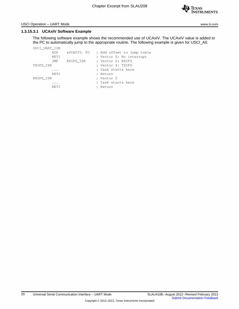
1.3.15.3.1 UCAxIV Software Example
The following software example shows the recommended use of UCAxIV. The UCAxIV value is added tothe PC to automatically jump to the appropriate routine. The following example is given for USCI_A0.USCI_UART_ISR
ADD &UCA0IV, PC ; Add offset to jump tableRETI ; Vector 0: No interruptJMP RXIFG_ISR ; Vector 2: RXIFG
TXIFG_ISR ; Vector 4: TXIFG... ; Task starts hereRETI ; Return
RXIFG_ISR ; Vector 2... ; Task starts hereRETI ; Return
20 Universal Serial Communication Interface – UART Mode SLAU410B–August 2012–Revised February 2013Submit Documentation Feedback
Copyright © 2012–2013, Texas Instruments Incorporated

Chapter Excerpt from SLAU208
www.ti.com USCI_A UART Mode Registers
1.4 USCI_A UART Mode Registers
The USCI registers applicable in UART mode listed in Table 1-6. The base address can be found in thedevice-specific data sheet. The address offsets are listed in Table 1-6.
Table 1-6. USCI_A UART Mode Registers
Offset Acronym Register Name Type Access Reset Section
00h UCAxCTLW0 USCI_Ax Control Word 0 Read/write Word 0001h
00h UCAxCTL1 USCI_Ax Control 1 Read/write Byte 01h Section 1.4.2
01h UCAxCTL0 USCI_Ax Control 0 Read/write Byte 00h Section 1.4.1
06h UCAxBRW USCI_Ax Baud Rate Control Word Read/write Word 0000h
06h UCAxBR0 USCI_Ax Baud Rate Control 0 Read/write Byte 00h Section 1.4.3
07h UCAxBR1 USCI_Ax Baud Rate Control 1 Read/write Byte 00h Section 1.4.4
08h UCAxMCTL USCI_Ax Modulation Control Read/write Byte 00h Section 1.4.5
09h Reserved - reads zero Read Byte 00h
0Ah UCAxSTAT USCI_Ax Status Read/write Byte 00h Section 1.4.6
0Bh Reserved - reads zero Read Byte 00h
0Ch UCAxRXBUF USCI_Ax Receive Buffer Read/write Byte 00h Section 1.4.7
0Dh Reserved - reads zero Read Byte 00h
0Eh UCAxTXBUF USCI_Ax Transmit Buffer Read/write Byte 00h Section 1.4.8
0Fh Reserved - reads zero Read Byte 00h
10h UCAxABCTL USCI_Ax Auto Baud Rate Control Read/write Byte 00h Section 1.4.11
11h Reserved - reads zero Read Byte 00h
12h UCAxIRCTL USCI_Ax IrDA Control Read/write Word 0000h
12h UCAxIRTCTL USCI_Ax IrDA Transmit Control Read/write Byte 00h Section 1.4.9
13h UCAxIRRCTL USCI_Ax IrDA Receive Control Read/write Byte 00h Section 1.4.10
1Ch UCAxICTL USCI_Ax Interrupt Control Read/write Word 0000h
1Ch UCAxIE USCI_Ax Interrupt Enable Read/write Byte 00h Section 1.4.12
1Dh UCAxIFG USCI_Ax Interrupt Flag Read/write Byte 00h Section 1.4.13
1Eh UCAxIV USCI_Ax Interrupt Vector Read Word 0000h Section 1.4.14
21SLAU410B–August 2012–Revised February 2013 Universal Serial Communication Interface – UART ModeSubmit Documentation Feedback
Copyright © 2012–2013, Texas Instruments Incorporated

Chapter Excerpt from SLAU208
USCI_A UART Mode Registers www.ti.com
1.4.1 UCAxCTL0 Register
USCI_Ax Control Register 0
Figure 1-12. UCAxCTL0 Register7 6 5 4 3 2 1 0
UCPEN UCPAR UCMSB UC7BIT UCSPB UCMODEx UCSYNC
rw-0 rw-0 rw-0 rw-0 rw-0 rw-0 rw-0 rw-0
Modify only when UCSWRST = 1.
Table 1-7. UCAxCTL0 Register Description
Bit Field Type Reset Description
7 UCPEN RW 0h Parity enable0b = Parity disabled1b = Parity enabled. Parity bit is generated (UCAxTXD) and expected(UCAxRXD). In address-bit multiprocessor mode, the address bit is included inthe parity calculation.
6 UCPAR RW 0h Parity select. UCPAR is not used when parity is disabled.0b = Odd parity1b = Even parity
5 UCMSB RW 0h MSB first select. Controls the direction of the receive and transmit shift register.0b = LSB first1b = MSB first
4 UC7BIT RW 0h Character length. Selects 7-bit or 8-bit character length.0b = 8-bit data1b = 7-bit data
3 UCSPB RW 0h Stop bit select. Number of stop bits.0b = One stop bit1b = Two stop bits
2-1 UCMODEx RW 0h USCI mode. The UCMODEx bits select the asynchronous mode when UCSYNC= 0.00b = UART mode01b = Idle-line multiprocessor mode10b = Address-bit multiprocessor mode11b = UART mode with automatic baud-rate detection
0 UCSYNC RW 0h Synchronous mode enable0b = Asynchronous mode1b = Synchronous mode
22 Universal Serial Communication Interface – UART Mode SLAU410B–August 2012–Revised February 2013Submit Documentation Feedback
Copyright © 2012–2013, Texas Instruments Incorporated

Chapter Excerpt from SLAU208
www.ti.com USCI_A UART Mode Registers
1.4.2 UCAxCTL1 Register
USCI_Ax Control Register 1
Figure 1-13. UCAxCTL1 Register7 6 5 4 3 2 1 0
UCSSELx UCRXEIE UCBRKIE UCDORM UCTXADDR UCTXBRK UCSWRST
rw-0 rw-0 rw-0 rw-0 rw-0 rw-0 rw-0 rw-1
Modify only when UCSWRST = 1.
Table 1-8. UCAxCTL1 Register Description
Bit Field Type Reset Description
7-6 UCSSELx RW 0h USCI clock source select. These bits select the BRCLK source clock.00b = UCAxCLK (external USCI clock)01b = ACLK10b = SMCLK11b = SMCLK
5 UCRXEIE RW 0h Receive erroneous-character interrupt enable0b = Erroneous characters rejected and UCRXIFG is not set.1b = Erroneous characters received set UCRXIFG.
4 UCBRKIE RW 0h Receive break character interrupt enable0b = Received break characters do not set UCRXIFG.1b = Received break characters set UCRXIFG.
3 UCDORM RW 0h Dormant. Puts USCI into sleep mode.0b = Not dormant. All received characters set UCRXIFG.1b = Dormant. Only characters that are preceded by an idle-line or with addressbit set UCRXIFG. In UART mode with automatic baud-rate detection, only thecombination of a break and synch field sets UCRXIFG.
2 UCTXADDR RW 0h Transmit address. Next frame to be transmitted is marked as address, dependingon the selected multiprocessor mode.0b = Next frame transmitted is data.1b = Next frame transmitted is an address.
1 UCTXBRK RW 0h Transmit break. Transmits a break with the next write to the transmit buffer. InUART mode with automatic baud-rate detection, 055h must be written intoUCAxTXBUF to generate the required break/synch fields. Otherwise, 0h must bewritten into the transmit buffer.0b = Next frame transmitted is not a break.1b = Next frame transmitted is a break or a break/synch.
0 UCSWRST RW 1h Software reset enable0b = Disabled. USCI reset released for operation.1b = Enabled. USCI logic held in reset state.
23SLAU410B–August 2012–Revised February 2013 Universal Serial Communication Interface – UART ModeSubmit Documentation Feedback
Copyright © 2012–2013, Texas Instruments Incorporated

Chapter Excerpt from SLAU208
USCI_A UART Mode Registers www.ti.com
1.4.3 UCAxBR0 Register
USCI_Ax Baud Rate Control Register 0
Figure 1-14. UCAxBR0 Register7 6 5 4 3 2 1 0
UCBRx
rw rw rw rw rw rw rw rw
Modify only when UCSWRST = 1.
Table 1-9. UCAxBR0 Register Description
Bit Field Type Reset Description
7-0 UCBRx RW undefine Low byte of clock prescaler setting of the baud-rate generator. The 16-bit valued of (UCAxBR0 + UCAxBR1 × 256) forms the prescaler value UCBRx.
1.4.4 UCAxBR1 Register
USCI_Ax Baud Rate Control Register 1
Figure 1-15. UCAxBR1 Register7 6 5 4 3 2 1 0
UCBRx
rw rw rw rw rw rw rw rw
Modify only when UCSWRST = 1.
Table 1-10. UCAxBR1 Register Description
Bit Field Type Reset Description
7-0 UCBRx RW undefined High byte of clock prescaler setting of the baud-rate generator. The 16-bit valueof (UCAxBR0 + UCAxBR1 × 256) forms the prescaler value UCBRx.
1.4.5 UCAxMCTL Register
USCI_Ax Modulation Control Register
Figure 1-16. UCAxMCTL Register7 6 5 4 3 2 1 0
UCBRFx UCBRSx UCOS16
rw-0 rw-0 rw-0 rw-0 rw-0 rw-0 rw-0 rw-0
Modify only when UCSWRST = 1.
Table 1-11. UCAxMCTL Register Description
Bit Field Type Reset Description
7-4 UCBRFx RW 0h First modulation stage select. These bits determine the modulation pattern forBITCLK16 when UCOS16 = 1. Ignored with UCOS16 = 0. Table 1-2 shows themodulation pattern.
3-1 UCBRSx RW 0h Second modulation stage select. These bits determine the modulation pattern forBITCLK. Table 1-2 shows the modulation pattern.
0 UCOS16 RW 0h Oversampling mode enabled0b = Disabled1b = Enabled
24 Universal Serial Communication Interface – UART Mode SLAU410B–August 2012–Revised February 2013Submit Documentation Feedback
Copyright © 2012–2013, Texas Instruments Incorporated

Chapter Excerpt from SLAU208
www.ti.com USCI_A UART Mode Registers
1.4.6 UCAxSTAT Register
USCI_Ax Status Register
Figure 1-17. UCAxSTAT Register7 6 5 4 3 2 1 0
UCLISTEN UCFE UCOE UCPE UCBRK UCRXERR UCADDR/ UCBUSYUCIDLE
rw-0 rw-0 rw-0 rw-0 rw-0 rw-0 rw-0 r-0
Modify only when UCSWRST = 1.
Table 1-12. UCAxSTAT Register Description
Bit Field Type Reset Description
7 UCLISTEN RW 0h Listen enable. The UCLISTEN bit selects loopback mode.0b = Disabled1b = Enabled. UCAxTXD is internally fed back to the receiver.
6 UCFE RW 0h Framing error flag. UCFE is cleared when UCAxRXBUF is read.0b = No error1b = Character received with low stop bit
5 UCOE RW 0h Overrun error flag. This bit is set when a character is transferred intoUCAxRXBUF before the previous character was read. UCOE is clearedautomatically when UCxRXBUF is read, and must not be cleared by software.Otherwise, it does not function correctly.0b = No error1b = Overrun error occurred
4 UCPE RW 0h Parity error flag. When UCPEN = 0, UCPE is read as 0. UCPE is cleared whenUCAxRXBUF is read.0b = No error1b = Character received with parity error
3 UCBRK RW 0h Break detect flag. UCBRK is cleared when UCAxRXBUF is read.0b = No break condition1b = Break condition occurred
2 UCRXERR RW 0h Receive error flag. This bit indicates a character was received with error(s).When UCRXERR = 1, on or more error flags, UCFE, UCPE, or UCOE is alsoset. UCRXERR is cleared when UCAxRXBUF is read.0b = No receive errors detected1b = Receive error detected
1 UCADDR/UCIDLE RW 0h UCADDR: Address received in address-bit multiprocessor mode. UCADDR iscleared when UCAxRXBUF is read.0b = Received character is data.1b = Received character is an address.UCIDLE: Idle line detected in idle-line multiprocessor mode. UCIDLE is clearedwhen UCAxRXBUF is read.0b = No idle line detected1b = Idle line detected
0 UCBUSY R 0h USCI busy. This bit indicates if a transmit or receive operation is in progress.0b = USCI inactive1b = USCI transmitting or receiving
25SLAU410B–August 2012–Revised February 2013 Universal Serial Communication Interface – UART ModeSubmit Documentation Feedback
Copyright © 2012–2013, Texas Instruments Incorporated

Chapter Excerpt from SLAU208
USCI_A UART Mode Registers www.ti.com
1.4.7 UCAxRXBUF Register
USCI_Ax Receive Buffer Register
Figure 1-18. UCAxRXBUF Register7 6 5 4 3 2 1 0
UCRXBUFx
r r r r r r r r
Table 1-13. UCAxRXBUF Register Description
Bit Field Type Reset Description
7-0 UCRXBUFx R undefined The receive-data buffer is user accessible and contains the last receivedcharacter from the receive shift register. Reading UCAxRXBUF resets thereceive-error bits, the UCADDR or UCIDLE bit, and UCRXIFG. In 7-bit datamode, UCAxRXBUF is LSB justified and the MSB is always reset.
1.4.8 UCAxTXBUF Register
USCI_Ax Transmit Buffer Register
Figure 1-19. UCAxTXBUF Register7 6 5 4 3 2 1 0
UCTXBUFx
rw rw rw rw rw rw rw rw
Table 1-14. UCAxTXBUF Register Description
Bit Field Type Reset Description
7-0 UCTXBUFx RW undefined The transmit data buffer is user accessible and holds the data waiting to bemoved into the transmit shift register and transmitted on UCAxTXD. Writing tothe transmit data buffer clears UCTXIFG. The MSB of UCAxTXBUF is not usedfor 7-bit data and is reset.
26 Universal Serial Communication Interface – UART Mode SLAU410B–August 2012–Revised February 2013Submit Documentation Feedback
Copyright © 2012–2013, Texas Instruments Incorporated

Chapter Excerpt from SLAU208
www.ti.com USCI_A UART Mode Registers
1.4.9 UCAxIRTCTL Register
USCI_Ax IrDA Transmit Control Register
Figure 1-20. UCAxIRTCTL Register7 6 5 4 3 2 1 0
UCIRTXPLx UCIRTXCLK UCIREN
rw-0 rw-0 rw-0 rw-0 rw-0 rw-0 rw-0 rw-0
Modify only when UCSWRST = 1.
Table 1-15. UCAxIRTCTL Register Description
Bit Field Type Reset Description
7-2 UCIRTXPLx RW 0h Transmit pulse length. Pulse length t(PULSE) = (UCIRTXPLx + 1) / [2 ×f(IRTXCLK)]
1 UCIRTXCLK RW 0h IrDA transmit pulse clock select0b = BRCLK1b = BITCLK16 when UCOS16 = 1. Otherwise, BRCLK.
0 UCIREN RW 0h IrDA encoder and decoder enable0b = IrDA encoder and decoder disabled1b = IrDA encoder and decoder enabled
1.4.10 UCAxIRRCTL Register
USCI_Ax IrDA Receive Control Register
Figure 1-21. UCAxIRRCTL Register7 6 5 4 3 2 1 0
UCIRRXFLx UCIRRXPL UCIRRXFE
rw-0 rw-0 rw-0 rw-0 rw-0 rw-0 rw-0 rw-0
Modify only when UCSWRST = 1.
Table 1-16. UCAxIRRCTL Register Description
Bit Field Type Reset Description
7-2 UCIRRXFLx RW 0h Receive filter length. The minimum pulse length for receive is given by: t(MIN) =(UCIRRXFLx + 4) / (2 × f(BRCLK))
1 UCIRRXPL RW 0h IrDA receive input UCAxRXD polarity0b = IrDA transceiver delivers a high pulse when a light pulse is seen.1b = IrDA transceiver delivers a low pulse when a light pulse is seen.
0 UCIRRXFE RW 0h IrDA receive filter enabled0b = Receive filter disabled1b = Receive filter enabled
27SLAU410B–August 2012–Revised February 2013 Universal Serial Communication Interface – UART ModeSubmit Documentation Feedback
Copyright © 2012–2013, Texas Instruments Incorporated
Chapter Excerpt from SLAU208
USCI_A UART Mode Registers www.ti.com
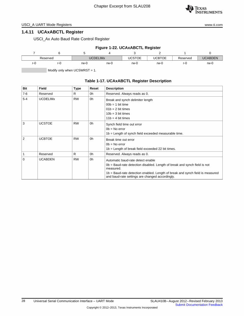
1.4.11 UCAxABCTL Register
USCI_Ax Auto Baud Rate Control Register
Figure 1-22. UCAxABCTL Register7 6 5 4 3 2 1 0
Reserved UCDELIMx UCSTOE UCBTOE Reserved UCABDEN
r-0 r-0 rw-0 rw-0 rw-0 rw-0 r-0 rw-0
Modify only when UCSWRST = 1.
Table 1-17. UCAxABCTL Register Description
Bit Field Type Reset Description
7-6 Reserved R 0h Reserved. Always reads as 0.
5-4 UCDELIMx RW 0h Break and synch delimiter length00b = 1 bit time01b = 2 bit times10b = 3 bit times11b = 4 bit times
3 UCSTOE RW 0h Synch field time out error0b = No error1b = Length of synch field exceeded measurable time.
2 UCBTOE RW 0h Break time out error0b = No error1b = Length of break field exceeded 22 bit times.
1 Reserved R 0h Reserved. Always reads as 0.
0 UCABDEN RW 0h Automatic baud-rate detect enable0b = Baud-rate detection disabled. Length of break and synch field is notmeasured.1b = Baud-rate detection enabled. Length of break and synch field is measuredand baud-rate settings are changed accordingly.
28 Universal Serial Communication Interface – UART Mode SLAU410B–August 2012–Revised February 2013Submit Documentation Feedback
Copyright © 2012–2013, Texas Instruments Incorporated

Chapter Excerpt from SLAU208
www.ti.com USCI_A UART Mode Registers
1.4.12 UCAxIE Register
USCI_Ax Interrupt Enable Register
Figure 1-23. UCAxIE Register7 6 5 4 3 2 1 0
Reserved UCTXIE UCRXIE
r-0 r-0 r-0 r-0 r-0 r-0 rw-0 rw-0
Table 1-18. UCAxIE Register Description
Bit Field Type Reset Description
7-2 Reserved R 0h Reserved. Always reads as 0.
1 UCTXIE RW 0h Transmit interrupt enable0b = Interrupt disabled1b = Interrupt enabled
0 UCRXIE RW 0h Receive interrupt enable0b = Interrupt disabled1b = Interrupt enabled
1.4.13 UCAxIFG Register
USCI_Ax Interrupt Flag Register
Figure 1-24. UCAxIFG Register7 6 5 4 3 2 1 0
Reserved UCTXIFG UCRXIFG
r-0 r-0 r-0 r-0 r-0 r-0 rw-1 rw-0
Table 1-19. UCAxIFG Register Description
Bit Field Type Reset Description
7-2 Reserved R 0h Reserved. Always reads as 0.
1 UCTXIFG RW 1h Transmit interrupt flag. UCTXIFG is set when UCAxTXBUF empty.0b = No interrupt pending1b = Interrupt pending
0 UCRXIFG RW 0h Receive interrupt flag. UCRXIFG is set when UCAxRXBUF has received acomplete character.0b = No interrupt pending1b = Interrupt pending
29SLAU410B–August 2012–Revised February 2013 Universal Serial Communication Interface – UART ModeSubmit Documentation Feedback
Copyright © 2012–2013, Texas Instruments Incorporated

Chapter Excerpt from SLAU208
USCI_A UART Mode Registers www.ti.com
1.4.14 UCAxIV Register
USCI_Ax Interrupt Vector Register
Figure 1-25. UCAxIV Register15 14 13 12 11 10 9 8
UCIVx
r0 r0 r0 r0 r0 r0 r0 r0
7 6 5 4 3 2 1 0
UCIVx
r0 r0 r0 r-0 r-0 r-0 r-0 r0
Table 1-20. UCAxIV Register Description
Bit Field Type Reset Description
15-0 UCIVx R 0h USCI interrupt vector value00h = No interrupt pending02h = Interrupt Source: Data received; Interrupt Flag: UCRXIFG; InterruptPriority: Highest04h = Interrupt Source: Transmit buffer empty; Interrupt Flag: UCTXIFG;Interrupt Priority: Lowest
30 Universal Serial Communication Interface – UART Mode SLAU410B–August 2012–Revised February 2013Submit Documentation Feedback
Copyright © 2012–2013, Texas Instruments Incorporated

IMPORTANT NOTICE
Texas Instruments Incorporated and its subsidiaries (TI) reserve the right to make corrections, enhancements, improvements and otherchanges to its semiconductor products and services per JESD46, latest issue, and to discontinue any product or service per JESD48, latestissue. Buyers should obtain the latest relevant information before placing orders and should verify that such information is current andcomplete. All semiconductor products (also referred to herein as “components”) are sold subject to TI’s terms and conditions of salesupplied at the time of order acknowledgment.
TI warrants performance of its components to the specifications applicable at the time of sale, in accordance with the warranty in TI’s termsand conditions of sale of semiconductor products. Testing and other quality control techniques are used to the extent TI deems necessaryto support this warranty. Except where mandated by applicable law, testing of all parameters of each component is not necessarilyperformed.
TI assumes no liability for applications assistance or the design of Buyers’ products. Buyers are responsible for their products andapplications using TI components. To minimize the risks associated with Buyers’ products and applications, Buyers should provideadequate design and operating safeguards.
TI does not warrant or represent that any license, either express or implied, is granted under any patent right, copyright, mask work right, orother intellectual property right relating to any combination, machine, or process in which TI components or services are used. Informationpublished by TI regarding third-party products or services does not constitute a license to use such products or services or a warranty orendorsement thereof. Use of such information may require a license from a third party under the patents or other intellectual property of thethird party, or a license from TI under the patents or other intellectual property of TI.
Reproduction of significant portions of TI information in TI data books or data sheets is permissible only if reproduction is without alterationand is accompanied by all associated warranties, conditions, limitations, and notices. TI is not responsible or liable for such altereddocumentation. Information of third parties may be subject to additional restrictions.
Resale of TI components or services with statements different from or beyond the parameters stated by TI for that component or servicevoids all express and any implied warranties for the associated TI component or service and is an unfair and deceptive business practice.TI is not responsible or liable for any such statements.
Buyer acknowledges and agrees that it is solely responsible for compliance with all legal, regulatory and safety-related requirementsconcerning its products, and any use of TI components in its applications, notwithstanding any applications-related information or supportthat may be provided by TI. Buyer represents and agrees that it has all the necessary expertise to create and implement safeguards whichanticipate dangerous consequences of failures, monitor failures and their consequences, lessen the likelihood of failures that might causeharm and take appropriate remedial actions. Buyer will fully indemnify TI and its representatives against any damages arising out of the useof any TI components in safety-critical applications.
In some cases, TI components may be promoted specifically to facilitate safety-related applications. With such components, TI’s goal is tohelp enable customers to design and create their own end-product solutions that meet applicable functional safety standards andrequirements. Nonetheless, such components are subject to these terms.
No TI components are authorized for use in FDA Class III (or similar life-critical medical equipment) unless authorized officers of the partieshave executed a special agreement specifically governing such use.
Only those TI components which TI has specifically designated as military grade or “enhanced plastic” are designed and intended for use inmilitary/aerospace applications or environments. Buyer acknowledges and agrees that any military or aerospace use of TI componentswhich have not been so designated is solely at the Buyer's risk, and that Buyer is solely responsible for compliance with all legal andregulatory requirements in connection with such use.
TI has specifically designated certain components as meeting ISO/TS16949 requirements, mainly for automotive use. In any case of use ofnon-designated products, TI will not be responsible for any failure to meet ISO/TS16949.
Products Applications
Audio www.ti.com/audio Automotive and Transportation www.ti.com/automotive
Amplifiers amplifier.ti.com Communications and Telecom www.ti.com/communications
Data Converters dataconverter.ti.com Computers and Peripherals www.ti.com/computers
DLP® Products www.dlp.com Consumer Electronics www.ti.com/consumer-apps
DSP dsp.ti.com Energy and Lighting www.ti.com/energy
Clocks and Timers www.ti.com/clocks Industrial www.ti.com/industrial
Interface interface.ti.com Medical www.ti.com/medical
Logic logic.ti.com Security www.ti.com/security
Power Mgmt power.ti.com Space, Avionics and Defense www.ti.com/space-avionics-defense
Microcontrollers microcontroller.ti.com Video and Imaging www.ti.com/video
RFID www.ti-rfid.com
OMAP Applications Processors www.ti.com/omap TI E2E Community e2e.ti.com
Wireless Connectivity www.ti.com/wirelessconnectivity
Mailing Address: Texas Instruments, Post Office Box 655303, Dallas, Texas 75265Copyright © 2013, Texas Instruments Incorporated