ua-5000 series user manual - icomtechinc.com · technical reference websites ... ua-5000 series...
TRANSCRIPT

ICP DAS CO., LTD.
UA-5000 Series User Manual
IIoT Communication Server
ICP DAS CO., LTD. All Rights Reserved.
www.icpdas.com

2
Warranty
All products manufactured by ICP DAS are under warranty regarding defective materials for a period of one
year, starting from the date of delivery to the original purchaser.
Warning
ICP DAS Inc., LTD. assumes no liability for damages consequent to the use of this product. ICP DAS Inc., LTD.
reserves the right to change this manual at any time without notice. The information furnished by ICP DAS
Inc. is believed to be accurate and reliable. However, no responsibility is assumed by ICP DAS Inc., LTD. for
its use, or for any infringements of patents or other rights of third parties resulting from its use.
Copyright and Trademark Information
© Copyright 2015 by ICP DAS Inc., LTD. All rights reserved worldwide.
Trademark of Other Companies
The names used for identification only maybe registered trademarks of their respective companies.
License
The user can use, modify and backup this software on a single machine. The user may not reproduce,
transfer or distribute this software, or any copy, in whole or in part.
Technical Service:
Please contact local agent or email problem-report to [email protected] .
For more product information, please refer to www.icpdas.com .
Technique: Sun Chen; Translation & Edition: Eva Li/Janice Hong ; R&D Dept., ICP DAS CO., LTD.
V.1.0.0 , Aug. 2015
UA-5000 Series User Manual V.1.0.0 ICP DAS
3
Table of Contents
1. UA-5000 IIoT Communication Server ........................................................................................................ 5
1.1. Introduction ...................................................................................................................................... 5
1.2. Function Features ............................................................................................................................. 6
1.3. Hardware Specifications ................................................................................................................... 7
1.4. Software Specifications ..................................................................................................................... 8
1.5. Appearance ....................................................................................................................................... 9
2. Quick Start ............................................................................................................................................... 11
2.1. Link to UA-5000 Web-based UI ....................................................................................................... 11
2.2. Add Variables in the Variable Table ................................................................................................ 15
2.3. Start a Built-in MQTT Broker ........................................................................................................... 18
2.4. Set Up the Driver, Virtual Device and Service ................................................................................. 19
2.4.1. Set up the Driver ................................................................................................................. 20
2.4.1.1. Example of the Modbus Driver settings................................................................ 20
2.4.1.2. Example of the MQTT Driver settings ................................................................... 24
2.4.2. Set Up the Virtual Device .................................................................................................... 28
2.4.2.1. Example of the PID settings .................................................................................. 28
2.4.3. Set Up the Service ............................................................................................................... 31
2.4.3.1. Set up the OPC UA Service .................................................................................... 31
2.4.3.2. Example of the MQTT Service ............................................................................... 31
2.5. Start the RunTime ........................................................................................................................... 36
3. System Functional Description ................................................................................................................ 37
3.1. System Management ...................................................................................................................... 37
3.1.1. System Information ............................................................................................................. 37
3.1.2. Main system setting ............................................................................................................ 38
3.1.3. MQTT Broker Setting ........................................................................................................... 39
3.1.4. Save the System Management settings .............................................................................. 39
3.2. Variable Setting ............................................................................................................................... 40
3.3. Driver ............................................................................................................................................... 42

UA-5000 Series User Manual V.1.0.0 ICP DAS
4
3.3.1. Modbus Master ................................................................................................................... 42
3.3.1.1. RTU ........................................................................................................................ 43
3.3.1.2. TCP ........................................................................................................................ 46
3.3.2. MQTT ................................................................................................................................... 49
3.4. Virtual Device .................................................................................................................................. 52
3.4.1. PID ....................................................................................................................................... 52
3.5. Service ............................................................................................................................................. 54
3.5.1. OPC UA ................................................................................................................................ 54
3.5.1.1. Redundancy Settings ............................................................................................. 54
3.5.1.2. Security ................................................................................................................. 55
3.5.2. MQTT ................................................................................................................................... 56
4. Technical Reference Websites ................................................................................................................. 59
OPC UA ...................................................................................................................................................... 59
MQTT ........................................................................................................................................................ 59
Modbus ..................................................................................................................................................... 59

UA-5000 Series User Manual V.1.0.0 ICP DAS
5
1. UA-5000 IIoT Communication Server
This chapter introducts the UA-5000 and its functions, software/hardware specifications...
1.1. Introduction
The UA-5000 is a series of data acquisition controller and also an IIoT communication server by ICP
DAS (IIoT: Industrial Internet of Things). The UA-5000 built-in OPC UA Server and MQTT Client
Service support a variety of common industrial communication protocols. Its RISC-based CPU
architecture has the advantages of small size and low power consumption that lets this series can
be placed in a small space to fit variety of rooms, equipment and case environment. In the
hardware, it provides a variety of communication interfaces, such as Gigabit Ethernet, USB, RS-232
and RS-485… ports to connect diverse devices.
Applying OPC UA can integrate the I/O products of ICP DAS with the third-party devices, import
the data information to the SCADA, database or decision-making systems for the back-end
management, and satisfy the reliability, interoperability and security needs of the industrial
automation system. Using MQTT communication can bridge the system with the Internet of
Things (IoT) to meet the current trend of the smart internet.

UA-5000 Series User Manual V.1.0.0 ICP DAS
6
1.2. Function Features
Web-based UI
With the Web-based User Interface, users can log in and configure the controller via a normal
web browser that only need a mobile device or computer with web browsing capabilities.
OPC UA Server: IEC 62541 Standard
The OPC UA Server certified by the OPC Foundation can assist the integration for the
local-end devices, actively upload data to the application system, and support to across the
multiple platforms.
PID Logic Operation
The PID function can dynamically combine the remote I/O devices for the PID logic control to
provide temperature control and case field solutions.
Support Modbus TCP/RTU Master
Through the controller's RS-485, RS-232 and Ethernet ports can connect to the Modbus
TCP/RTU Slave devices. Build systems with scalability and flexibility to meet the diverse
application needs and expansion at any time.
MQTT Broker Inside
Compliance with MQTT v3.1.1 protocol. Support MQTT message distribution management.
Users do not need to build Broker system when using MQTT communications.
Support MQTT Protocol
Support MQTT to allow the IoT devices communicating with the OPC UA system and the
UA-5000 conducting the data acquisition and management; and also can convert and publish
the devices' data under the UA-5000 to the IoT system.
UA-5000 Series User Manual V.1.0.0 ICP DAS
7
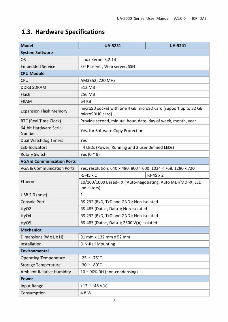
1.3. Hardware Specifications
Model UA-5231 UA-5241
System Software
OS Linux Kernel 3.2.14
Embedded Service SFTP server, Web server, SSH
CPU Module
CPU AM3352, 720 MHz
DDR3 SDRAM 512 MB
Flash 256 MB
FRAM 64 KB
Expansion Flash Memory microSD socket with one 4 GB microSD card (support up to 32 GB microSDHC card)
RTC (Real Time Clock) Provide second, minute, hour, date, day of week, month, year
64-bit Hardware Serial Number
Yes, for Software Copy Protection
Dual Watchdog Timers Yes
LED Indicators 4 LEDs (Power, Running and 2 user defined LEDs)
Rotary Switch Yes (0 ~ 9)
VGA & Communication Ports
VGA & Communication Ports Yes, resolution: 640 × 480, 800 × 600, 1024 × 768, 1280 x 720
Ethernet
RJ-45 x 1 RJ-45 x 2
10/100/1000 Based-TX ( Auto-negotiating, Auto MDI/MDI-X, LED indicators)
USB 2.0 (host) 1
Console Port RS-232 (RxD, TxD and GND); Non-isolated
ttyO2 RS-485 (Data+, Data-); Non-isolated
ttyO4 RS-232 (RxD, TxD and GND); Non-isolated
ttyO5 RS-485 (Data+, Data-); 2500 VDC isolated
Mechanical
Dimensions (W x L x H) 91 mm x 132 mm x 52 mm
Installation DIN-Rail Mounting
Environmental
Operating Temperature -25 ~ +75°C
Storage Temperature -30 ~ +80°C
Ambient Relative Humidity 10 ~ 90% RH (non-condensing)
Power
Input Range +12 ~ +48 VDC
Consumption 4.8 W

UA-5000 Series User Manual V.1.0.0 ICP DAS
8
1.4. Software Specifications
Model UA-5000 Series
OPC UA
OPC UA Server
OPC Unified Architecture: 1.02 Core Server Facet Data Access Server Facet Method Server Facet Client Redundancy Facet UA-TCP UA-SC UA Binary User Token User Name Password & X509 Certificate Security Policy
○None
○Basic128Rsa15
• Sign • Sign & Encrypt
○Basic256
• Sign • Sign & Encrypt
Modbus Master
Modbus TCP To read or control the devices that support standard Modbus TCP Slave protocol. Recommend to keep the maximum number of devices within 100 connections.
Modbus RTU A max. of 3 ports: ttyO2, ttyO4, ttyO5 to connect other Modbus RTU Slave devices (e.g. M-7000). Recommend no more than 32 devices per port for better communication quality.
MQTT
MQTT Client Connect the MQTT Broker to read/control the devices supporting the MQTT protocol.
MQTT Service Connect the MQTT Broker to externally read/control the devices supporting other protocols that linking with the UA-5000 series.
MQTT Broker Compliance with MQTT v3.1.1 protocol. Support MQTT message distribution management. Recommend to keep the connection number of Client within 400.
Virtual Device
PID Function Combine the remote I/O devices for the PID logic control system.

UA-5000 Series User Manual V.1.0.0 ICP DAS
9
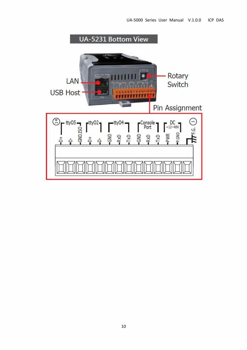
1.5. Appearance
UA-5000 Series User Manual V.1.0.0 ICP DAS
10

UA-5000 Series User Manual V.1.0.0 ICP DAS
11
2. Quick Start
This chapter describes the process of creating a UA-5000 project, including how to connect to the
UA-5000 web-based UI via a browser, set web functions step-by-step, and complete a project.
2.1. Link to UA-5000 Web-based UI
The following steps will show you how to connect to the UA-5000 web interface.
Using the UA-5000 Utility (named “UA-5000utility.exe”) at the path of the companion CD (i.e.,
CD:/UA-5000/Utility/). Please copy this file to your PC, and then run it to connect the device.
Step 1 Run the UA-5000 Utility (file name: UA-5000utility.exe).

UA-5000 Series User Manual V.1.0.0 ICP DAS
12
Step 2 Add a connection item and give a name for it.
Step 3 Mouse double-click on the name you created (or single-click and then click the “Connect” button),
this utility will search and list all devices over the network.
1
2

UA-5000 Series User Manual V.1.0.0 ICP DAS
13
Step 4 Click the device name you want to connect to, and then click the “Connect” button. It will connect
to the UA-5000 web interface via the default browser.
Step 5 A login dialog box will appear, entering your user name and password, and then click “OK”.
The factory default user name and password are “root”.
2
1

UA-5000 Series User Manual V.1.0.0 ICP DAS
14
Finish After logging into the web interface, you can see the main configuration screen.

UA-5000 Series User Manual V.1.0.0 ICP DAS
15
2.2. Add Variables in the Variable Table
The following steps will show you how to add variables in the variable table.
Step 1 Click “Variable Setting” on the left to open the setting page.
Step 2 Click “Add” to add the needed variable.
UA-5000 Series User Manual V.1.0.0 ICP DAS
16
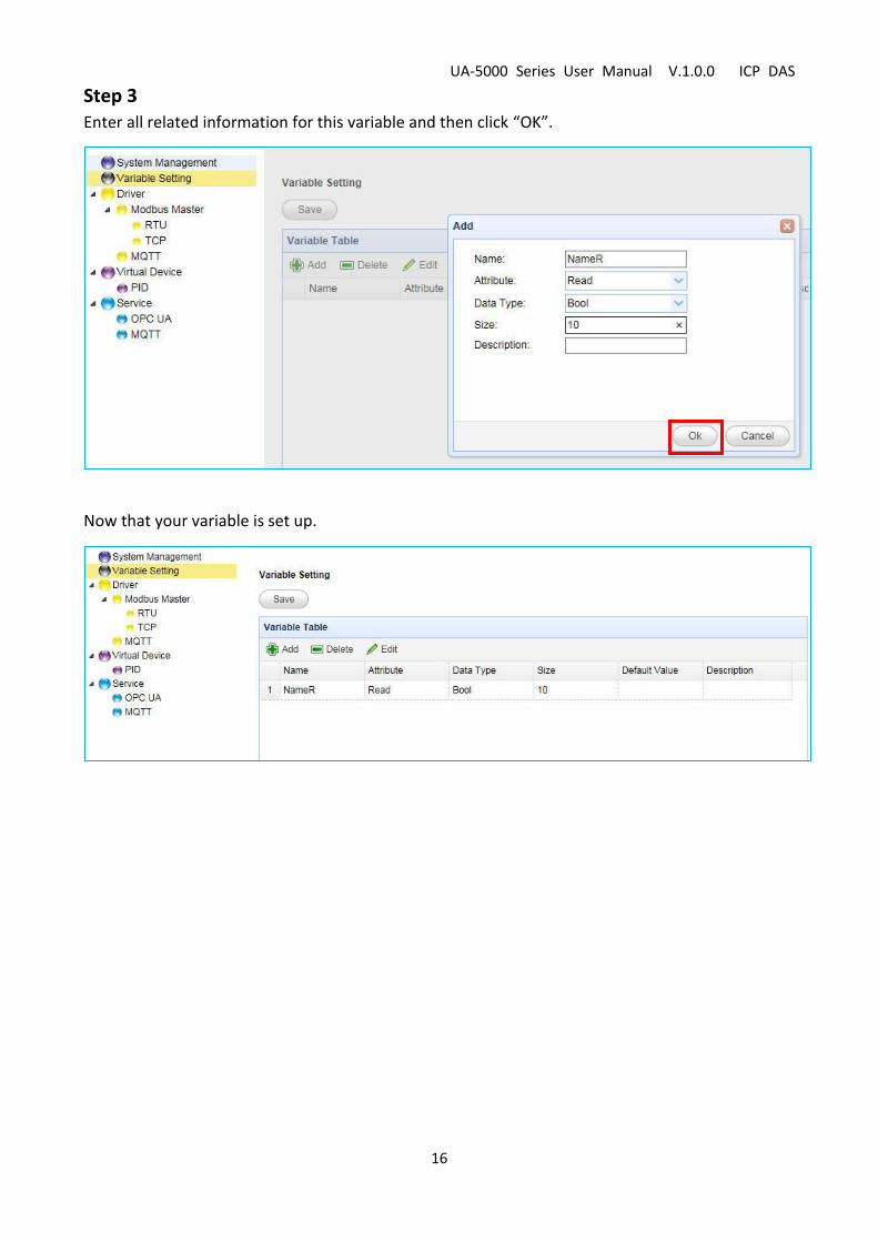
Step 3 Enter all related information for this variable and then click “OK”.
Now that your variable is set up.
UA-5000 Series User Manual V.1.0.0 ICP DAS
17
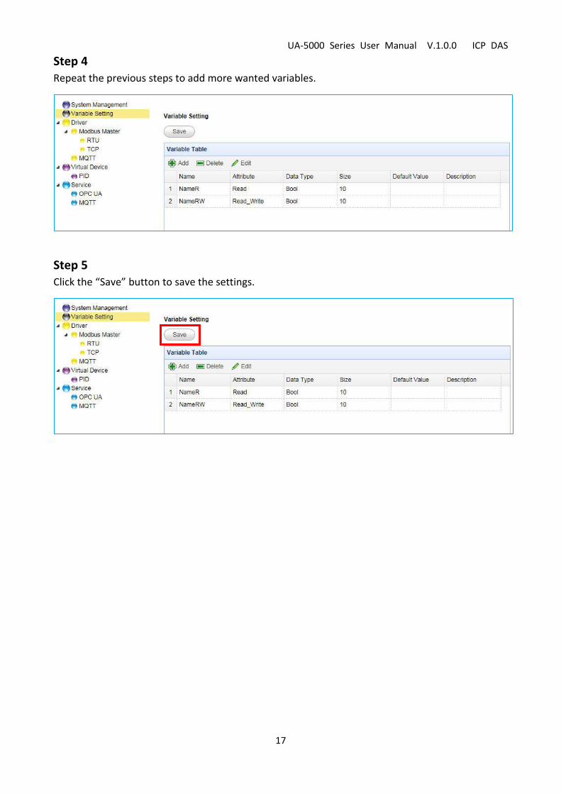
Step 4 Repeat the previous steps to add more wanted variables.
Step 5 Click the “Save” button to save the settings.

UA-5000 Series User Manual V.1.0.0 ICP DAS
18
2.3. Start a Built-in MQTT Broker
Step 1 Click “System Management” on the left tree-menu, and then click the “MQTT Broker Setting” tab
in the right panel.
Step 2 Click “Start” to execute the Broker. When it marked in gray that means the Broker is running.
UA-5000 Series User Manual V.1.0.0 ICP DAS
19
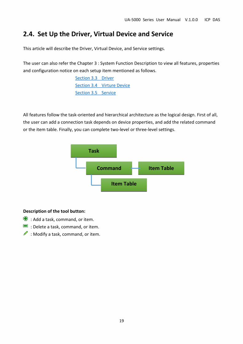
2.4. Set Up the Driver, Virtual Device and Service
This article will describe the Driver, Virtual Device, and Service settings.
The user can also refer the Chapter 3 : System Function Description to view all features, properties
and configuration notice on each setup item mentioned as follows.
Section 3.3 Driver
Section 3.4 Virture Device
Section 3.5 Service
All features follow the task-oriented and hierarchical architecture as the logical design. First of all,
the user can add a connection task depends on device properties, and add the related command
or the item table. Finally, you can complete two-level or three-level settings.
Description of the tool button:
: Add a task, command, or item.
: Delete a task, command, or item.
: Modify a task, command, or item.
Command
Task
Item Table
Item Table

UA-5000 Series User Manual V.1.0.0 ICP DAS
20
2.4.1. Set up the Driver
The Driver setting is divided into the Modbus Driver setting and the MQTT Driver setting.
2.4.1.1. Example of the Modbus Driver settings
In this example, we use Modbus TCP protocol to conduct the Modbus Driver setting. The user can
also refer the Chapter 3 - System Function Description - Section 3.3 Driver to view all features,
properties and configuration notice for each item mentioned in this section.
Step 1 Add all needed variables in the variable table. (See Section 2.2)
Step 2 On the tree menu to the left, click “Driver > Modbus Master > TCP”, and add a connection task.
1
2

UA-5000 Series User Manual V.1.0.0 ICP DAS
21
Step 3 In the Task table, add a Modbus command and enter all parameters.
Step 4 After completing it, you can see this two-level (Task > Command) table.
1
2
UA-5000 Series User Manual V.1.0.0 ICP DAS
22
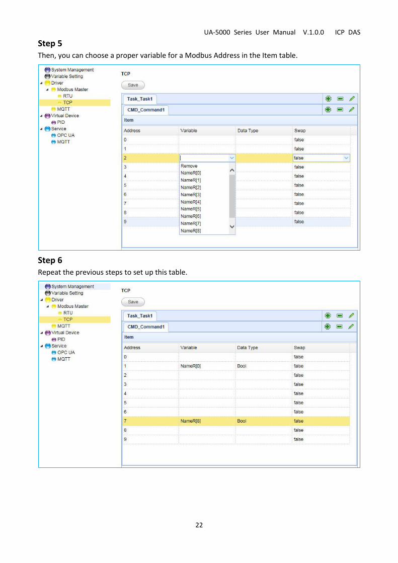
Step 5 Then, you can choose a proper variable for a Modbus Address in the Item table.
Step 6 Repeat the previous steps to set up this table.

UA-5000 Series User Manual V.1.0.0 ICP DAS
23
Step 7 Save all settings.
UA-5000 Series User Manual V.1.0.0 ICP DAS
24
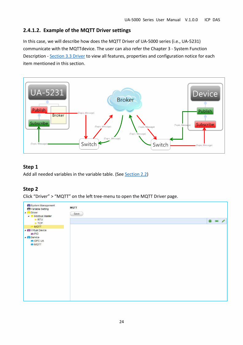
2.4.1.2. Example of the MQTT Driver settings
In this case, we will describe how does the MQTT Driver of UA-5000 series (i.e., UA-5231)
communicate with the MQTTdevice. The user can also refer the Chapter 3 - System Function
Description - Section 3.3 Driver to view all features, properties and configuration notice for each
item mentioned in this section.
Step 1 Add all needed variables in the variable table. (See Section 2.2)
Step 2 Click “Driver” > “MQTT” on the left tree-menu to open the MQTT Driver page.

UA-5000 Series User Manual V.1.0.0 ICP DAS
25
Step 3 Add a MQTT Driver task. Enter task name and Broker settings, and then click “OK”.
Step 4 In the Item table, click “Add” to add variable and edit its topic.
1
2
UA-5000 Series User Manual V.1.0.0 ICP DAS
26
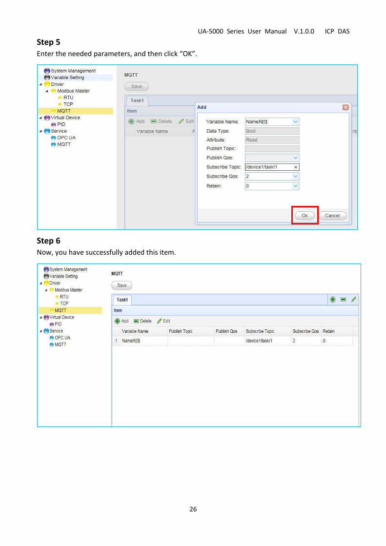
Step 5 Enter the needed parameters, and then click “OK”.
Step 6 Now, you have successfully added this item.

UA-5000 Series User Manual V.1.0.0 ICP DAS
27
Step 7 Follow the previos steps to add several settings.
Step 8 Save the settings.
UA-5000 Series User Manual V.1.0.0 ICP DAS
28
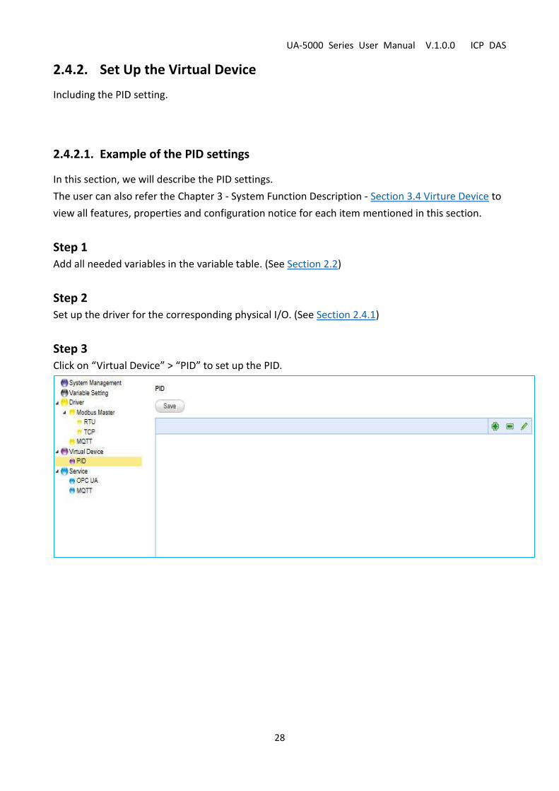
2.4.2. Set Up the Virtual Device
Including the PID setting.
2.4.2.1. Example of the PID settings
In this section, we will describe the PID settings.
The user can also refer the Chapter 3 - System Function Description - Section 3.4 Virture Device to
view all features, properties and configuration notice for each item mentioned in this section.
Step 1 Add all needed variables in the variable table. (See Section 2.2)
Step 2 Set up the driver for the corresponding physical I/O. (See Section 2.4.1)
Step 3 Click on “Virtual Device” > “PID” to set up the PID.
UA-5000 Series User Manual V.1.0.0 ICP DAS
29
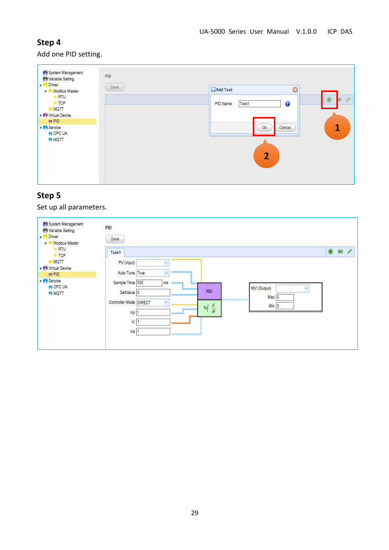
Step 4 Add one PID setting.
Step 5 Set up all parameters.
1
2

UA-5000 Series User Manual V.1.0.0 ICP DAS
30
Step 6 Save all settings.

UA-5000 Series User Manual V.1.0.0 ICP DAS
31
2.4.3. Set Up the Service
The Service setting is divided into the OPC UA Service and the MQTT Service.
2.4.3.1. Set up the OPC UA Service
The OPC UA Server is a system service and enabled by default. When the user assign variables in
the Driver and Virtual Device panels, the configuration for the OPC UA Server will also be done,
that is, no more settings to do.
2.4.3.2. Example of the MQTT Service
The UA-5000’s MQTT Service is used to convert other Driver’s data into the MQTT message. Using
a user-defined topic as an index to receive the data sending from other MQTT devices.
The following steps will show you the way to convert the Modbus Master Driver’s data into the
MQTT message. The user can also refer the Chapter 3 - System Function Description - Section 3.5
Service to view all features, properties and configuration notice for each item mentioned in this
section.
Step 1 Add all needed variables in the variable table. (See Section 2.2)

UA-5000 Series User Manual V.1.0.0 ICP DAS
32
Step 2 Set up the Modbus Driver, and assign variables to the Driver. (See Section 2.4.1)
Step 3 Set up the MQTT Service. Click “Service” > “MQTT” on the left.
Step 4 Add a task for this MQTT service. After completing it, click “OK”.
1
2

UA-5000 Series User Manual V.1.0.0 ICP DAS
33
Step 5 Click the “Add” button under the “Task” tab you added before.
Step 6 In the pop-up “Add” dialog box, enter the needed variable and parameters. Then, click “OK”.

UA-5000 Series User Manual V.1.0.0 ICP DAS
34
Step 7 Now, you have successfully added this item.
Step 8 Repeat the previous steps to add several items.
UA-5000 Series User Manual V.1.0.0 ICP DAS
35
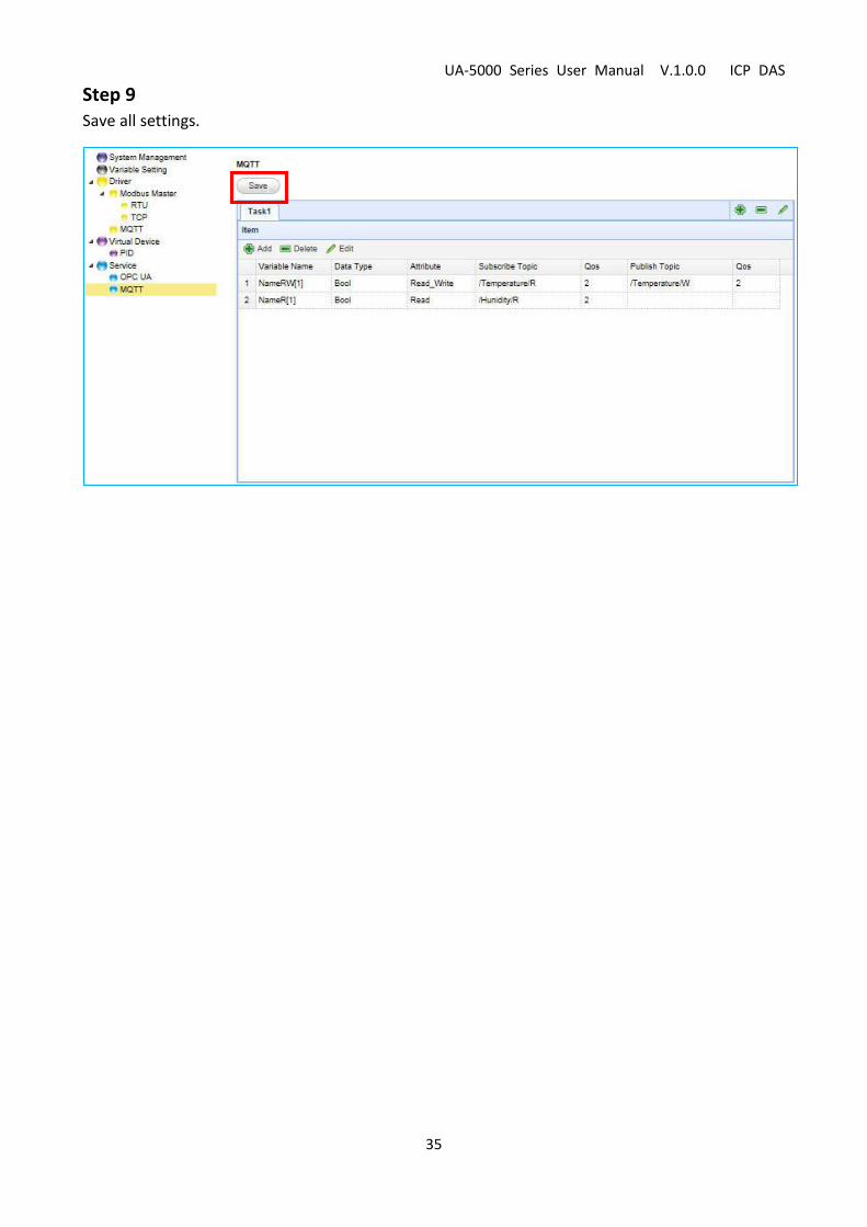
Step 9 Save all settings.

UA-5000 Series User Manual V.1.0.0 ICP DAS
36
2.5. Start the RunTime
This section will describe how to start the UA-5000 series’s RunTime.
When the user finish the project setting and want to start the system runtime, simply switch to
the “Main System Setting” page in the “System Management” panel, and then click “Start”.
While “Start” is marked in gray, it means the system is running.

UA-5000 Series User Manual V.1.0.0 ICP DAS
37
3. System Functional Description
In the chapter, we will explain all functions and parameters on the following topics that listed in
the UA-5000’s Web UI (as the figure below).
3.1. System Management
This section will describe how to use the “System Management”
function and save all settings. It includes the “System Information”,
“Main System” and “MQTT Broker” settings.
3.1.1. System Information
To display or modify the system information.
Function items Description Default
IP Address The IP address of the UA-5000. System value
Netmask The mask address of the UA-5000. System value
Host Name The host name of the UA-5000. System value
User Name The login name for the UA-5000’s Web UI.
Password The login password for the UA-5000’s Web UI.
Date Time/Time zone setting,
NTP network time synchronization.
System value

UA-5000 Series User Manual V.1.0.0 ICP DAS
38
3.1.2. Main system setting
To display or modify the current status for the main system setting.
Function items Description Default
Main System status Display the current status of the main system and allows
switching this function. Stop
Run at startup Whether to run at startup. Uncheck

UA-5000 Series User Manual V.1.0.0 ICP DAS
39
3.1.3. MQTT Broker Setting
To display or modify the current status for the MQTT Broker setting.
Function items Description Default
MQTT Broker status Display the current status of the Broker and allows
switching this function.
Start
Port MQTT Broker’s COM port. 1883
Run at startup Whether to run at startup. Uncheck
3.1.4. Save the System Management settings
Click the “Modify” button to save the currnt settings.
UA-5000 Series User Manual V.1.0.0 ICP DAS
40
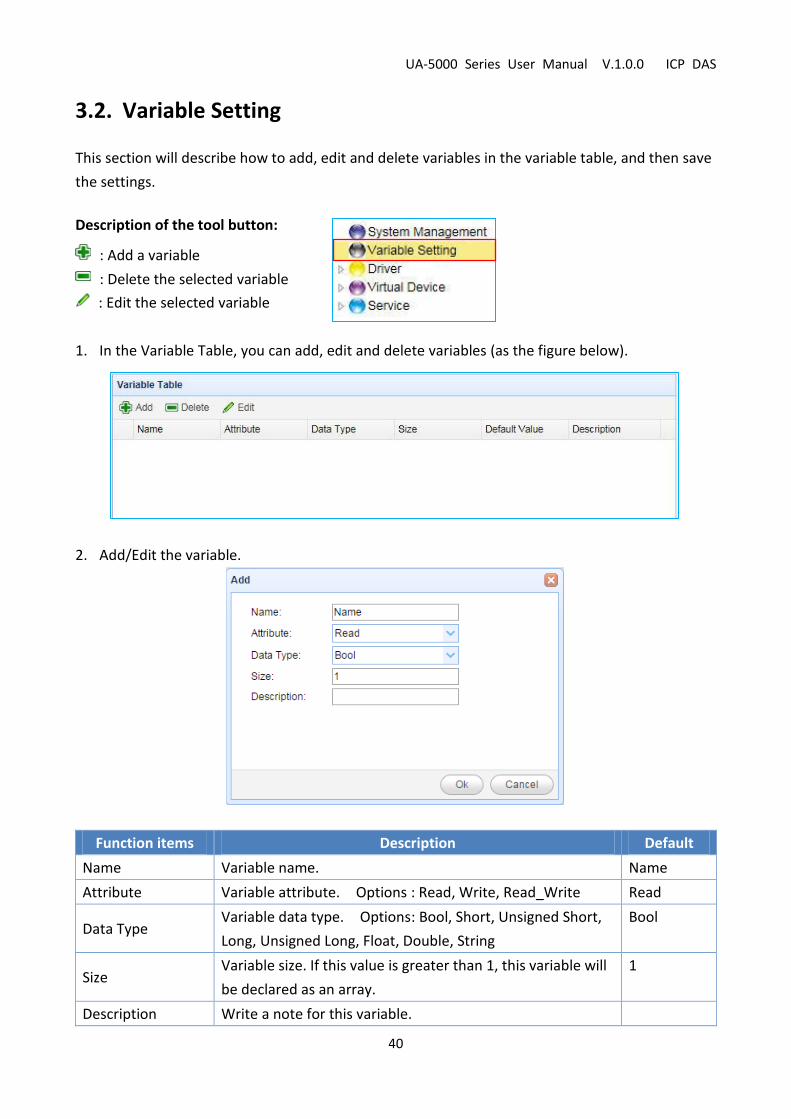
3.2. Variable Setting
This section will describe how to add, edit and delete variables in the variable table, and then save
the settings.
Description of the tool button:
: Add a variable
: Delete the selected variable
: Edit the selected variable
1. In the Variable Table, you can add, edit and delete variables (as the figure below).
2. Add/Edit the variable.
Function items Description Default
Name Variable name. Name
Attribute Variable attribute. Options : Read, Write, Read_Write Read
Data Type Variable data type. Options: Bool, Short, Unsigned Short,
Long, Unsigned Long, Float, Double, String
Bool
Size Variable size. If this value is greater than 1, this variable will
be declared as an array.
1
Description Write a note for this variable.

UA-5000 Series User Manual V.1.0.0 ICP DAS
41
3. Click “Ok” to complete the setting.
4. Click “Save” to save the current settings.
UA-5000 Series User Manual V.1.0.0 ICP DAS
42
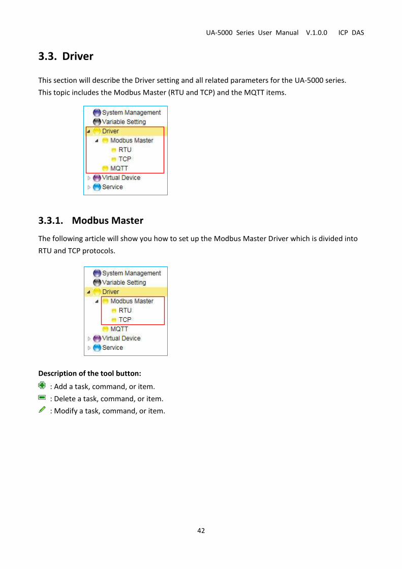
3.3. Driver
This section will describe the Driver setting and all related parameters for the UA-5000 series.
This topic includes the Modbus Master (RTU and TCP) and the MQTT items.
3.3.1. Modbus Master
The following article will show you how to set up the Modbus Master Driver which is divided into
RTU and TCP protocols.
Description of the tool button:
: Add a task, command, or item.
: Delete a task, command, or item.
: Modify a task, command, or item.
UA-5000 Series User Manual V.1.0.0 ICP DAS
43
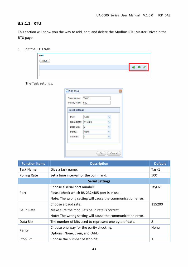
3.3.1.1. RTU
This section will show you the way to add, edit, and delete the Modbus RTU Master Driver in the
RTU page.
1. Edit the RTU task.
The Task settings:
Function items Description Default
Task Name Give a task name. Task1
Polling Rate Set a time interval for the command. 500
Serial Settings
Port
Choose a serial port number.
Please check which RS-232/485 port is in use.
Note: The wrong setting will cause the communication error.
TtyO2
Baud Rate
Choose a baud rate.
Make sure the module’s baud rate is correct.
Note: The wrong setting will cause the communication error.
115200
Data Bits The number of bits used to represent one byte of data. 8
Parity Choose one way for the parity checking.
Options: None, Even, and Odd.
None
Stop Bit Choose the number of stop bit. 1

UA-5000 Series User Manual V.1.0.0 ICP DAS
44
2. Configure the command under the task tab.
The Command settings:
Function items Description Default
Command Name Give a command name. Command1
Function Definition
Data Model Choose the data type for the Modbus command. 02 Input Status(1x)
Slave ID Set the Slave ID of the UA-5000.
(Range: 1 ~ 247)
1
Start Address The start address of the Modbus command. 0
Length The number of the Modbus address. 10
Timeout Set the timeout value for the module. 500
UA-5000 Series User Manual V.1.0.0 ICP DAS
45
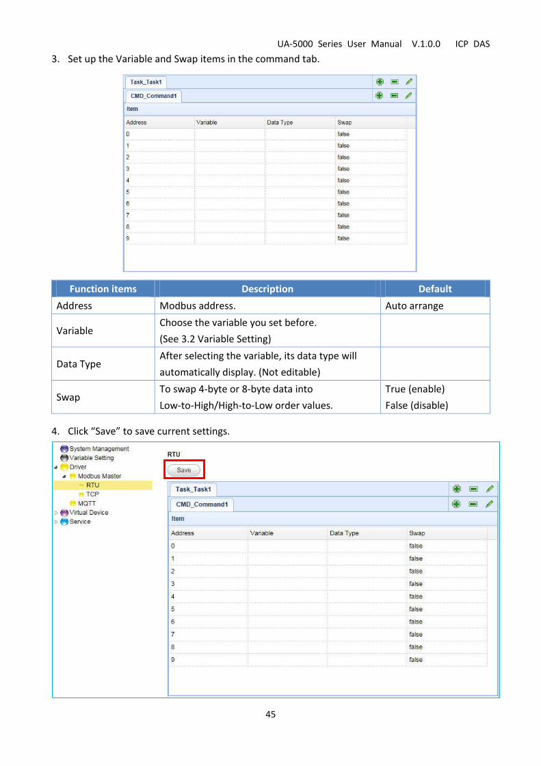
3. Set up the Variable and Swap items in the command tab.
Function items Description Default
Address Modbus address. Auto arrange
Variable Choose the variable you set before.
(See 3.2 Variable Setting)
Data Type After selecting the variable, its data type will
automatically display. (Not editable)
Swap To swap 4-byte or 8-byte data into
Low-to-High/High-to-Low order values.
True (enable)
False (disable)
4. Click “Save” to save current settings.

UA-5000 Series User Manual V.1.0.0 ICP DAS
46
3.3.1.2. TCP
This section will show you the way to add, edit, and delete the Modbus RTU Master Driver in the
TCP page.
1. Edit the TCP task.
The Task settings:
Function items Description Default
Task Name Give a task name. Task1
Polling Rate Set an interval time for each command. 500
Ethernet
IP The IP address of the connected device. 127.0.0.1
Port The port number for Modbus TCP. 502

UA-5000 Series User Manual V.1.0.0 ICP DAS
47
2. Configure the command under the task tab.
The Command settings:
Function items Description Default
Command Name Give a command name. Command1
Function Definition
Data Model Choose the data type for the Modbus command. 02 Input Status(1x)
Slave ID Set the Slave ID of the UA-5000.
(Range: 1 ~ 247)
1
Start Address The start address of the Modbus command. 0
Length The number of the Modbus address. 10
Timeout Set the timeout value for the module. 500
UA-5000 Series User Manual V.1.0.0 ICP DAS
48
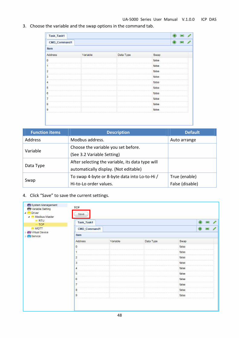
3. Choose the variable and the swap options in the command tab.
Function items Description Default
Address Modbus address. Auto arrange
Variable Choose the variable you set before.
(See 3.2 Variable Setting)
Data Type After selecting the variable, its data type will
automatically display. (Not editable)
Swap To swap 4-byte or 8-byte data into Lo-to-Hi /
Hi-to-Lo order values.
True (enable)
False (disable)
4. Click “Save” to save the current settings.

UA-5000 Series User Manual V.1.0.0 ICP DAS
49
3.3.2. MQTT
This section will show you the way to add, modify, and delete the MQTT driver in the MQTT page.
Description of the tool button:
: Add a task, command, or item.
: Delete a task, command, or item.
: Modify a task, command, or item.
1. Edit the MQTT task.
The Task settings:
Function items Description Default
Task Name Give a task name. Task1
Broker Setting
IP The IP address of the Broker. Syatem value
Port The Broker port. 1883
Keepalive Keepalive time. 60

UA-5000 Series User Manual V.1.0.0 ICP DAS
50
2. Configure the variable and related parameters under the MQTT task tab.
The settings:
Function items Description Default
Variable Name Choose a variable which pre-defined in the variable table.
Data Type Not editable. It will show the data type of a variable. System value
Attribute Not editable. It will show the variable attribute. System value
Publish Topic The topic of sending data or publishing messages.
Publish Qos
The Quality of Service (Qos) levels.
0: Delivering a message at most once.
1: Delivering a message at least once.
2: Delivering a message at exactly once.
2
Subscribe Topic The topic of receiving data or subscribing messages.
Subscribe Qos
The Quality of Service (Qos) levels.
0: Delivering a message at most once.
1: Delivering a message at least once.
2: Delivering a message at exactly once.
2
Retain Whether to store a broker message. (0: No ; 1: Yes) 0
UA-5000 Series User Manual V.1.0.0 ICP DAS
51
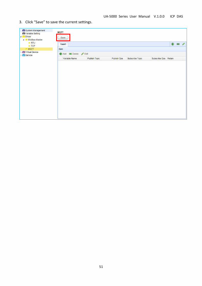
3. Click “Save” to save the current settings.

UA-5000 Series User Manual V.1.0.0 ICP DAS
52
3.4. Virtual Device
This Virtual Device function allows the user to simulate various devices with the real I/O by using
the PID tuning function. This article includes the PID function.
3.4.1. PID
This section will show you the way to add, modify, and delete the virtual PID device in the PID
page. Proportional-Integral-Derivative control is the most widely used in industrial control systems.
A regulator which is controlled in accordance with Proportional, Integral and Derivative is called
PID contol for short, also called PID regulator. When the user cannot fully grasp or measur
parameters of the control system, the PID regulator is the best solution.
Description of the tool button:
: Add a task, command, or item.
: Delete a task, command, or item.
: Modify a task, command, or item.
1. Configure a task in the PID Device page.
The settings:
Function items Description Default
PID Name Give a PID task name. Task1
UA-5000 Series User Manual V.1.0.0 ICP DAS
53
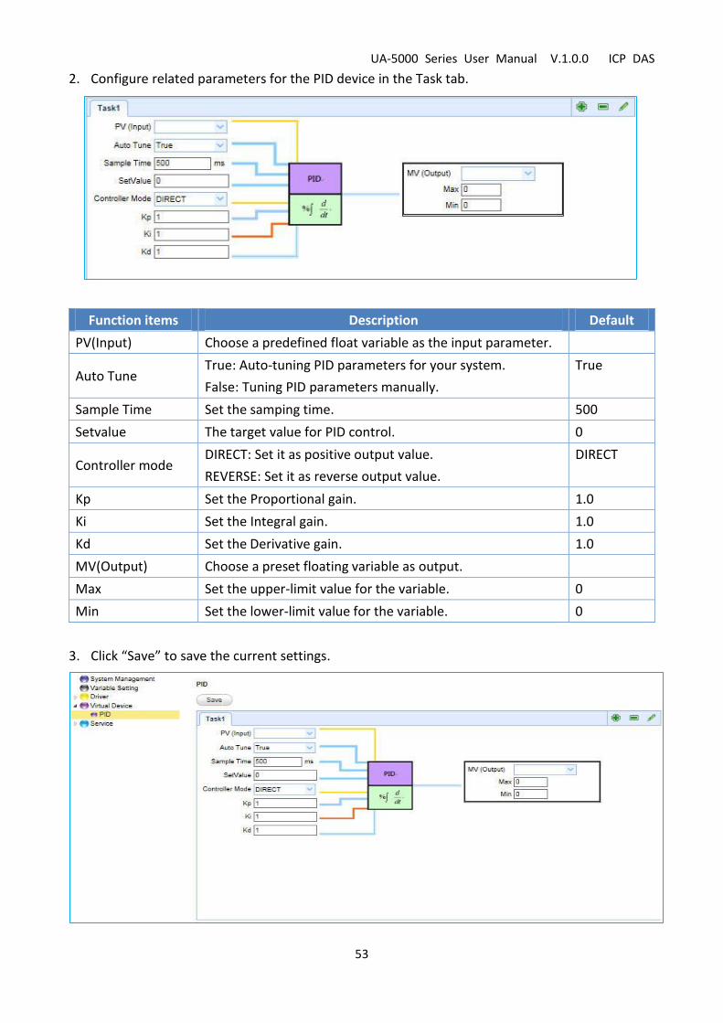
2. Configure related parameters for the PID device in the Task tab.
Function items Description Default
PV(Input) Choose a predefined float variable as the input parameter.
Auto Tune True: Auto-tuning PID parameters for your system.
False: Tuning PID parameters manually.
True
Sample Time Set the samping time. 500
Setvalue The target value for PID control. 0
Controller mode DIRECT: Set it as positive output value.
REVERSE: Set it as reverse output value.
DIRECT
Kp Set the Proportional gain. 1.0
Ki Set the Integral gain. 1.0
Kd Set the Derivative gain. 1.0
MV(Output) Choose a preset floating variable as output.
Max Set the upper-limit value for the variable. 0
Min Set the lower-limit value for the variable. 0
3. Click “Save” to save the current settings.

UA-5000 Series User Manual V.1.0.0 ICP DAS
54
3.5. Service
This section will describe how to configure the “Service” funtion.
It includes the OPC UA and MQTT items.
3.5.1. OPC UA
This section will show you the way to configure the Redundancy and Security settings.
3.5.1.1.Redundancy Settings
Function items Description Default
Redundancy Support
Mode Select the redundant mode. System value
Local Host
IP Display the IP address of the active OPC UA Server. System value
Server Name Display the active OPC UA Server name. Not editable. ICPDAS_OPC_UA_Server
Port The TCP port number of the active OPC UA Server. 48010
Activate Driver Check: Driver will run at system startup.
Uncheck: Driver will run if a network is available.
Uncheck
Redundant Server
IP The IP address of the redundant OPC UA Server.
Server Name Display the redundant OPC UA Server name.
Not editable.
ICPDAS_OPC_UA_Server
Port The TCP port number of the redundant OPC UA Server. 48010

UA-5000 Series User Manual V.1.0.0 ICP DAS
55
3.5.1.2. Security
Function items Description Default
User Identity Tokens
Enable Anonymous Check: Allow clients to use anonymous access .
Uncheck: No anonymous login.
Check
Enable User Password Check: Allow to log in with username/password.
Uncheck: Not supported this way.
Uncheck
Enable Certificate Check: Allow to log in with certificates
Uncheck: Not supported this way.
Uncheck
Click “Save” to save the OPC Ua settings.
UA-5000 Series User Manual V.1.0.0 ICP DAS
56
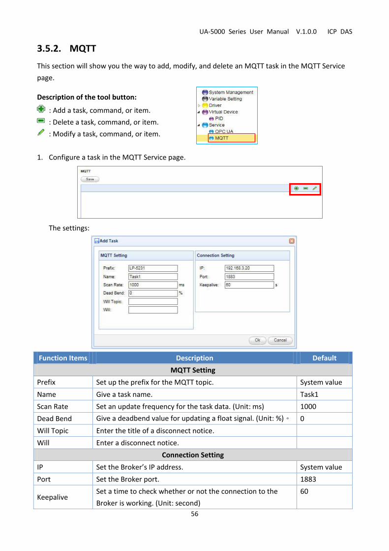
3.5.2. MQTT
This section will show you the way to add, modify, and delete an MQTT task in the MQTT Service
page.
Description of the tool button:
: Add a task, command, or item.
: Delete a task, command, or item.
: Modify a task, command, or item.
1. Configure a task in the MQTT Service page.
The settings:
Function Items Description Default
MQTT Setting
Prefix Set up the prefix for the MQTT topic. System value
Name Give a task name. Task1
Scan Rate Set an update frequency for the task data. (Unit: ms) 1000
Dead Bend Give a deadbend value for updating a float signal. (Unit: %)。 0
Will Topic Enter the title of a disconnect notice.
Will Enter a disconnect notice.
Connection Setting
IP Set the Broker’s IP address. System value
Port Set the Broker port. 1883
Keepalive Set a time to check whether or not the connection to the
Broker is working. (Unit: second)
60
UA-5000 Series User Manual V.1.0.0 ICP DAS
57
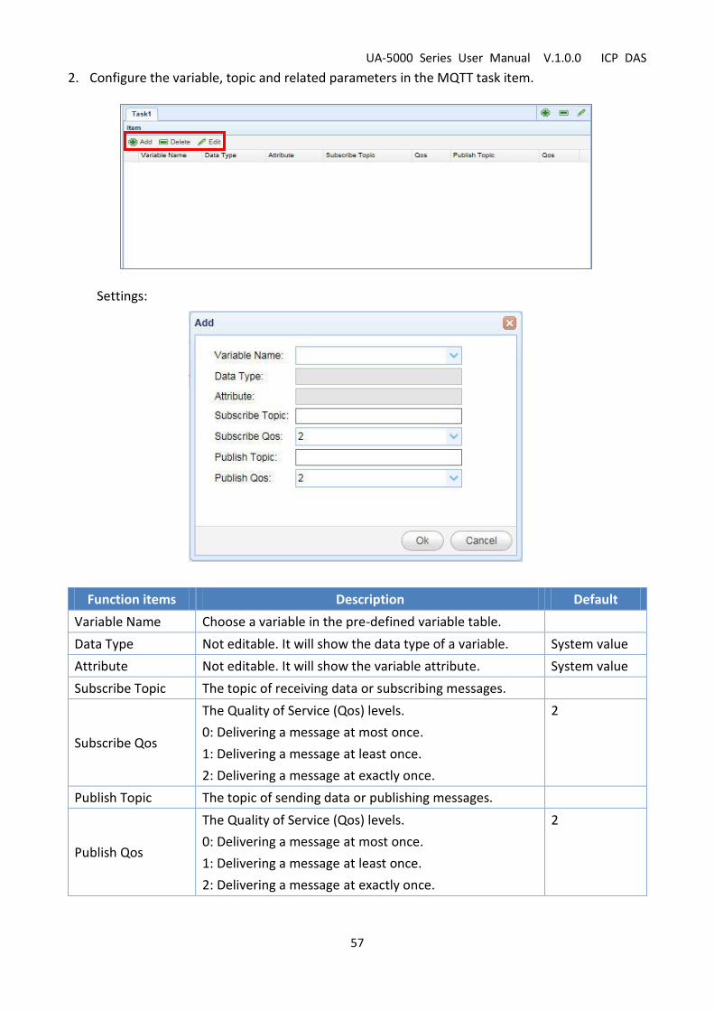
2. Configure the variable, topic and related parameters in the MQTT task item.
Settings:
Function items Description Default
Variable Name Choose a variable in the pre-defined variable table.
Data Type Not editable. It will show the data type of a variable. System value
Attribute Not editable. It will show the variable attribute. System value
Subscribe Topic The topic of receiving data or subscribing messages.
Subscribe Qos
The Quality of Service (Qos) levels.
0: Delivering a message at most once.
1: Delivering a message at least once.
2: Delivering a message at exactly once.
2
Publish Topic The topic of sending data or publishing messages.
Publish Qos
The Quality of Service (Qos) levels.
0: Delivering a message at most once.
1: Delivering a message at least once.
2: Delivering a message at exactly once.
2
UA-5000 Series User Manual V.1.0.0 ICP DAS
58
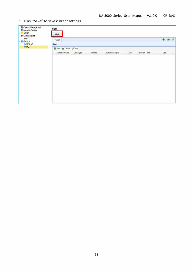
3. Click “Save” to save current settings.

UA-5000 Series User Manual V.1.0.0 ICP DAS
59
4. Technical Reference Websites
OPC UA
https://opcfoundation.org/
MQTT
http://mqtt.org/
Modbus
http://modbus.org/