u3 p1 gating system
TRANSCRIPT

Manufacturing Technology II(ME-202)
Overview of Manufacturing
Processes
Dr. Chaitanya Sharma
PhD. IIT Roorkee
Title of slide
Lesson ObjectivesIn this chapter we shall discuss the following:Need for gating systemElements of gating system
Learning Activities1. Look up
Keywords2. View Slides; 3. Read Notes, 4. Listen to
lecture
Keywords:Pouring basin, sprue, runner, riser, gates, in-gate, dross formation
Gating System
• A good gating design should ensure proper distributionof molten metal without excessive temperature loss,turbulence, gas entrapping and slags.
• Very slow pouring, require longer filling time andsolidification will start even before filling of mould.
• This can be restricted by using super heated metal, butin this case gas solubility will be a problem.
• Faster pouring can erode the mould cavity.
• So gating design is important and it depends on themetal and molten metal composition. For example,aluminium can get oxidized easily.
Casting Design and Fluidity Test
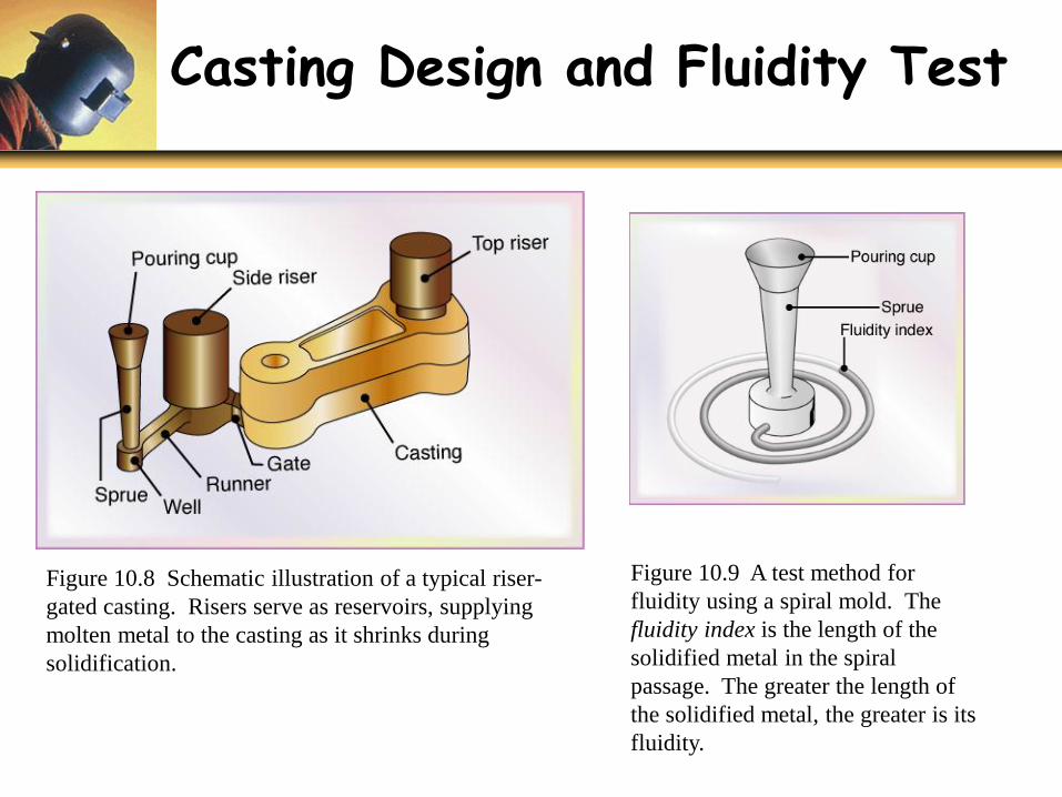
Figure 10.8 Schematic illustration of a typical riser-
gated casting. Risers serve as reservoirs, supplying
molten metal to the casting as it shrinks during
solidification.
Figure 10.9 A test method for
fluidity using a spiral mold. The
fluidity index is the length of the
solidified metal in the spiral
passage. The greater the length of
the solidified metal, the greater is its
fluidity.
Gating System
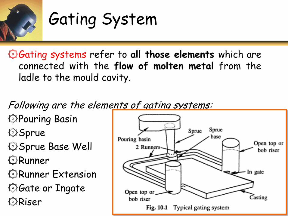
۞Gating systems refer to all those elements which areconnected with the flow of molten metal from theladle to the mould cavity.
Following are the elements of gating systems:
۞Pouring Basin
۞Sprue
۞Sprue Base Well
۞Runner
۞Runner Extension
۞Gate or Ingate
۞Riser
CHARACTERISTICS OF GATING SYSTEM
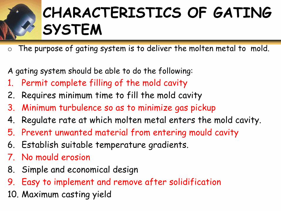
o The purpose of gating system is to deliver the molten metal to mold.
A gating system should be able to do the following:
1. Permit complete filling of the mold cavity
2. Requires minimum time to fill the mold cavity
3. Minimum turbulence so as to minimize gas pickup
4. Regulate rate at which molten metal enters the mold cavity.
5. Prevent unwanted material from entering mould cavity
6. Establish suitable temperature gradients.
7. No mould erosion
8. Simple and economical design
9. Easy to implement and remove after solidification
10. Maximum casting yield
Factor Affecting PerformanceOf Gating System
• To achieve sound casting and other objectives following factors should be controlled properly:
1. The type of ladle and ladle equipment.
2. The size, type, and location of sprue and runner.
3. The size, number & location of gates entering mold cavity.
4. The rate of pouring.
5. The position of the mold during casting.
6. The temperature and fluidity of the metal.
Objective of The Gating System
The four main points, which enables a proper gating system, are:
1. Clean molten metal.
2. Smooth filling of the casting cavity.
3. Uniform filling of the casting cavity.
4. Complete filling of the casting cavity.
• The mold cavity must be filled with a clean metal so thatit prevents the entry of slag and inclusions into the moldcavity, which in turn minimizes the surface instability.
• If the mold has smooth filling then it helps to reduce thebulk turbulence. If it has a uniform filling it means thatthe casting fill is in a controlled manner.
• Complete filling of the cavity makes the metal thin withminimum resistance at the end sections.
Elements of Gating System
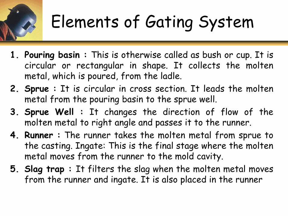
1. Pouring basin : This is otherwise called as bush or cup. It iscircular or rectangular in shape. It collects the moltenmetal, which is poured, from the ladle.
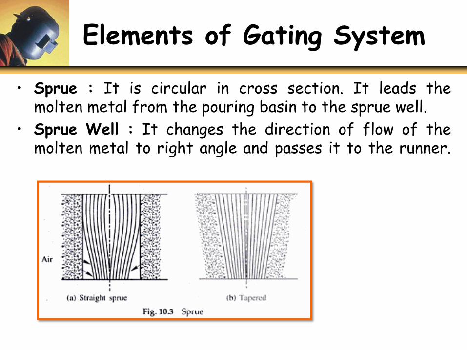
2. Sprue : It is circular in cross section. It leads the moltenmetal from the pouring basin to the sprue well.
3. Sprue Well : It changes the direction of flow of themolten metal to right angle and passes it to the runner.
4. Runner : The runner takes the molten metal from sprue tothe casting. Ingate: This is the final stage where the moltenmetal moves from the runner to the mold cavity.
5. Slag trap : It filters the slag when the molten metal movesfrom the runner and ingate. It is also placed in the runner
Elements of Gating System
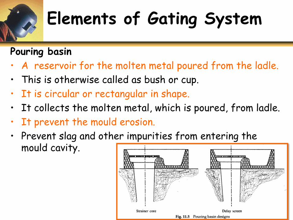
Pouring basin
• A reservoir for the molten metal poured from the ladle.
• This is otherwise called as bush or cup.
• It is circular or rectangular in shape.
• It collects the molten metal, which is poured, from ladle.
• It prevent the mould erosion.
• Prevent slag and other impurities from entering the mould cavity.
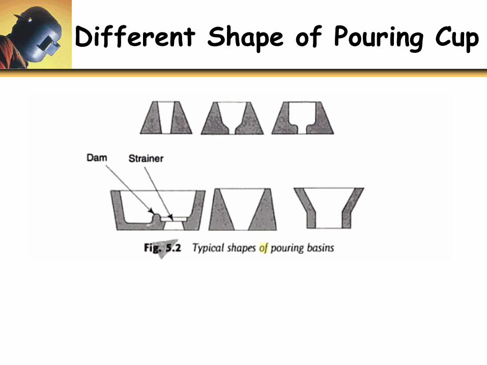
Different Shape of Pouring Cup
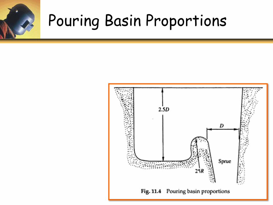
Pouring Basin Proportions
Elements of Gating System
• Sprue : It is circular in cross section. It leads themolten metal from the pouring basin to the sprue well.
• Sprue Well : It changes the direction of flow of themolten metal to right angle and passes it to the runner.
Elements of Gating System
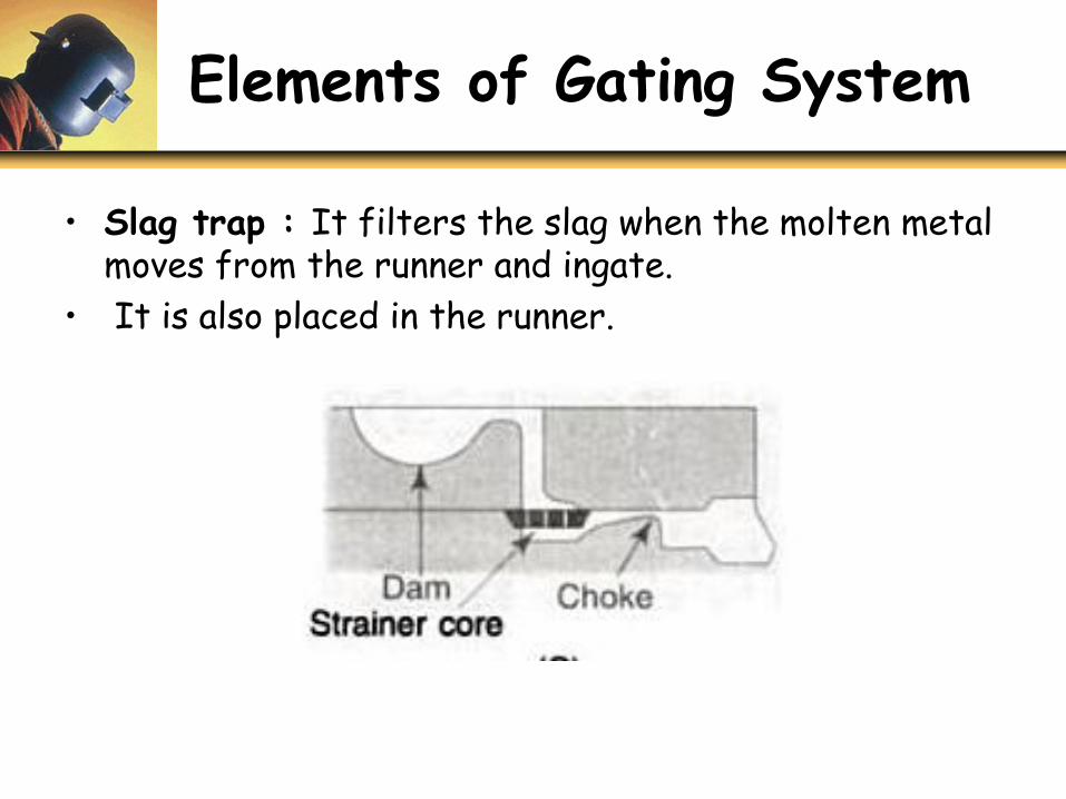
• Slag trap : It filters the slag when the molten metal moves from the runner and ingate.
• It is also placed in the runner.
Elements Of Gating System
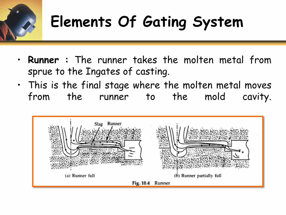
• Runner : The runner takes the molten metal fromsprue to the Ingates of casting.
• This is the final stage where the molten metal movesfrom the runner to the mold cavity.
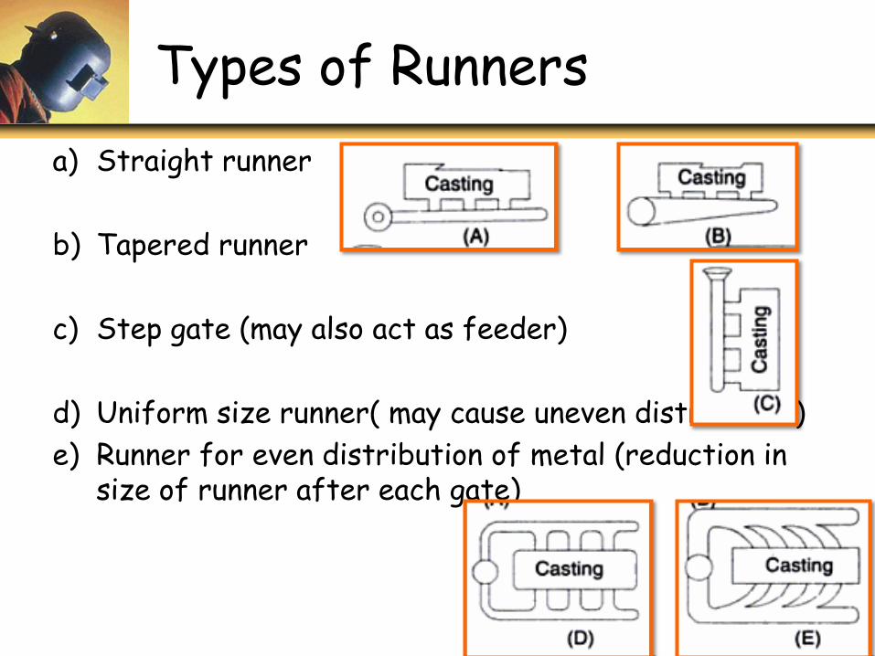
Types of Runners
a) Straight runner
b) Tapered runner
c) Step gate (may also act as feeder)
d) Uniform size runner( may cause uneven distribution)
e) Runner for even distribution of metal (reduction in size of runner after each gate)
Types of Gating System
Main types of gates are following:
1. Vertical Gating System
2.Bottom Gating System
3.Horizontal Gating System
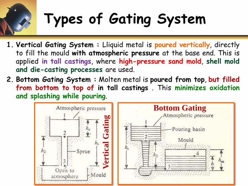
Types of Gating System
1. Vertical Gating System : Lliquid metal is poured vertically, directlyto fill the mould with atmospheric pressure at the base end. This isapplied in tall castings, where high-pressure sand mold, shell moldand die-casting processes are used.
2. Bottom Gating System : Molten metal is poured from top, but filledfrom bottom to top of in tall castings . This minimizes oxidationand splashing while pouring.
Bottom GatingV
erti
cal
Gati
ng
Types of Gating system
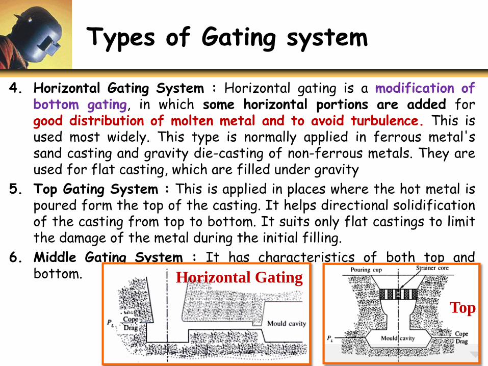
4. Horizontal Gating System : Horizontal gating is a modification ofbottom gating, in which some horizontal portions are added forgood distribution of molten metal and to avoid turbulence. This isused most widely. This type is normally applied in ferrous metal'ssand casting and gravity die-casting of non-ferrous metals. They areused for flat casting, which are filled under gravity
5. Top Gating System : This is applied in places where the hot metal ispoured form the top of the casting. It helps directional solidificationof the casting from top to bottom. It suits only flat castings to limitthe damage of the metal during the initial filling.
6. Middle Gating System : It has characteristics of both top andbottom. Horizontal Gating
Top
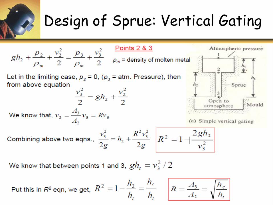
Analysis of Vertical Gating
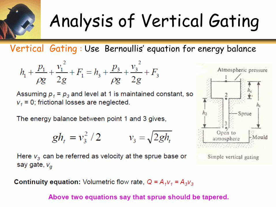
Vertical Gating : Use Bernoullis’ equation for energy balance
continued
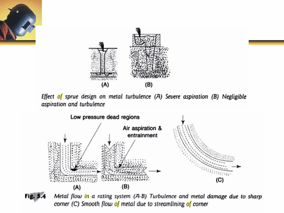
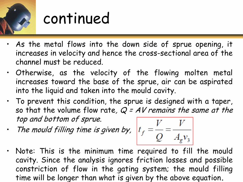
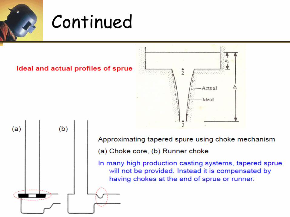
• As the metal flows into the down side of sprue opening, itincreases in velocity and hence the cross-sectional area of thechannel must be reduced.
• Otherwise, as the velocity of the flowing molten metalincreases toward the base of the sprue, air can be aspiratedinto the liquid and taken into the mould cavity.
• To prevent this condition, the sprue is designed with a taper,so that the volume flow rate, Q = AV remains the same at thetop and bottom of sprue.
• The mould filling time is given by,
• Note: This is the minimum time required to fill the mouldcavity. Since the analysis ignores friction losses and possibleconstriction of flow in the gating system; the mould fillingtime will be longer than what is given by the above equation.
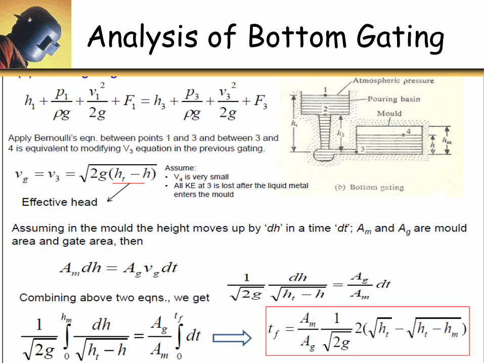
Analysis of Bottom Gating
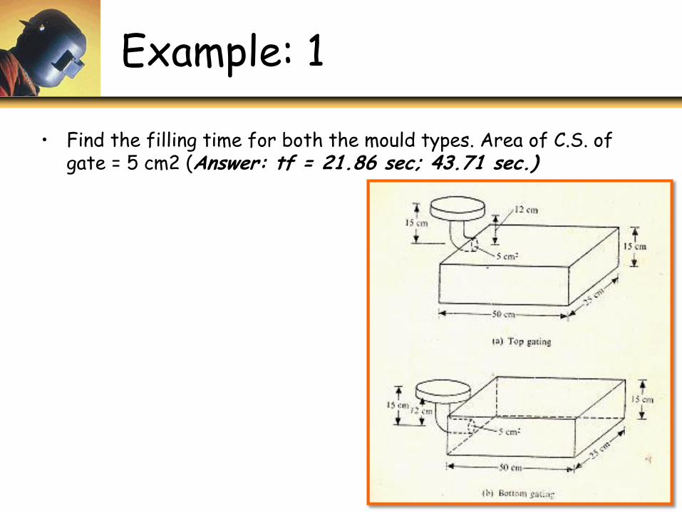
Example: 1
• Find the filling time for both the mould types. Area of C.S. of gate = 5 cm2 (Answer: tf = 21.86 sec; 43.71 sec.)
Aspiration Effect
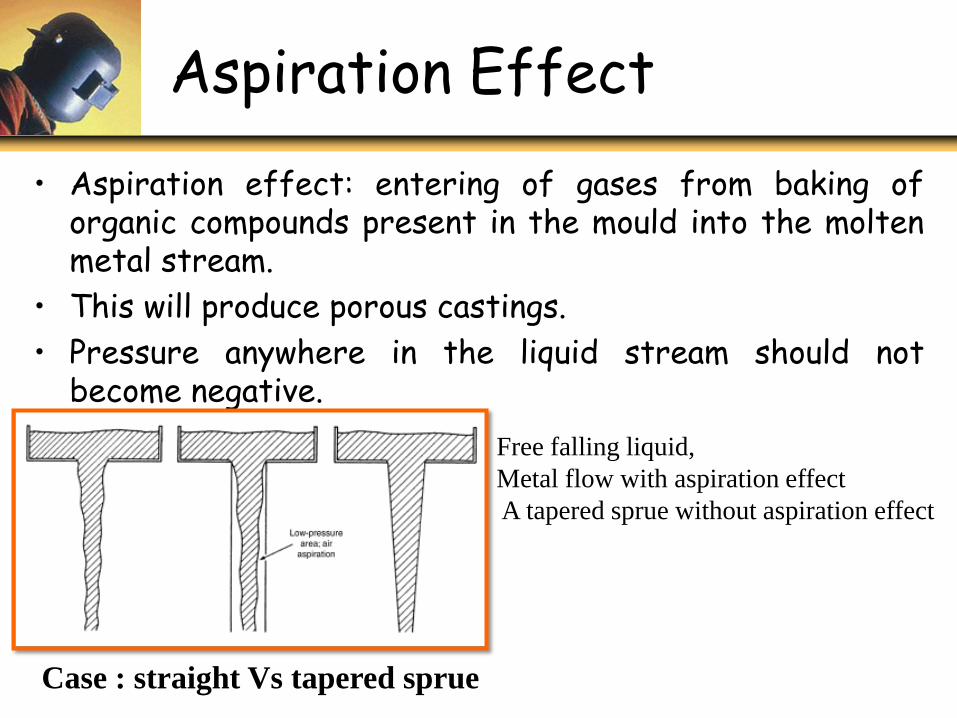
• Aspiration effect: entering of gases from baking oforganic compounds present in the mould into the moltenmetal stream.
• This will produce porous castings.
• Pressure anywhere in the liquid stream should notbecome negative.
Free falling liquid,
Metal flow with aspiration effect
A tapered sprue without aspiration effect
Case : straight Vs tapered sprue
Design of Sprue: Vertical Gating
Continued
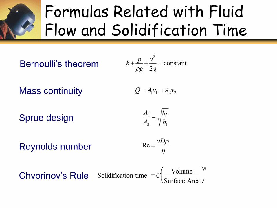
Formulas Related with Fluid Flow and Solidification Time
Sprue design
A1
A2
h2
h1
Mass continuity
Q A1v1 A2v2
Bernoulli’s theorem
hp
gv2
2g constant
Reynolds number
Re vD
Chvorinov’s Rule
Solidification time =CVolume
Surface Area
n
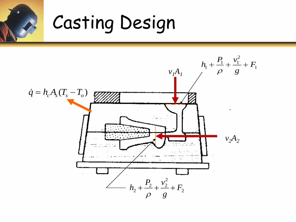
Casting Design
1
2
111 F
g
vPh
2
2
222 F
g
vPh
v2A2
v1A1
)( ossc TTAhq
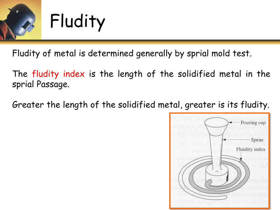
Fludity
Fludity of metal is determined generally by sprial mold test.
The fludity index is the length of the solidified metal in thesprial Passage.
Greater the length of the solidified metal, greater is its fludity.
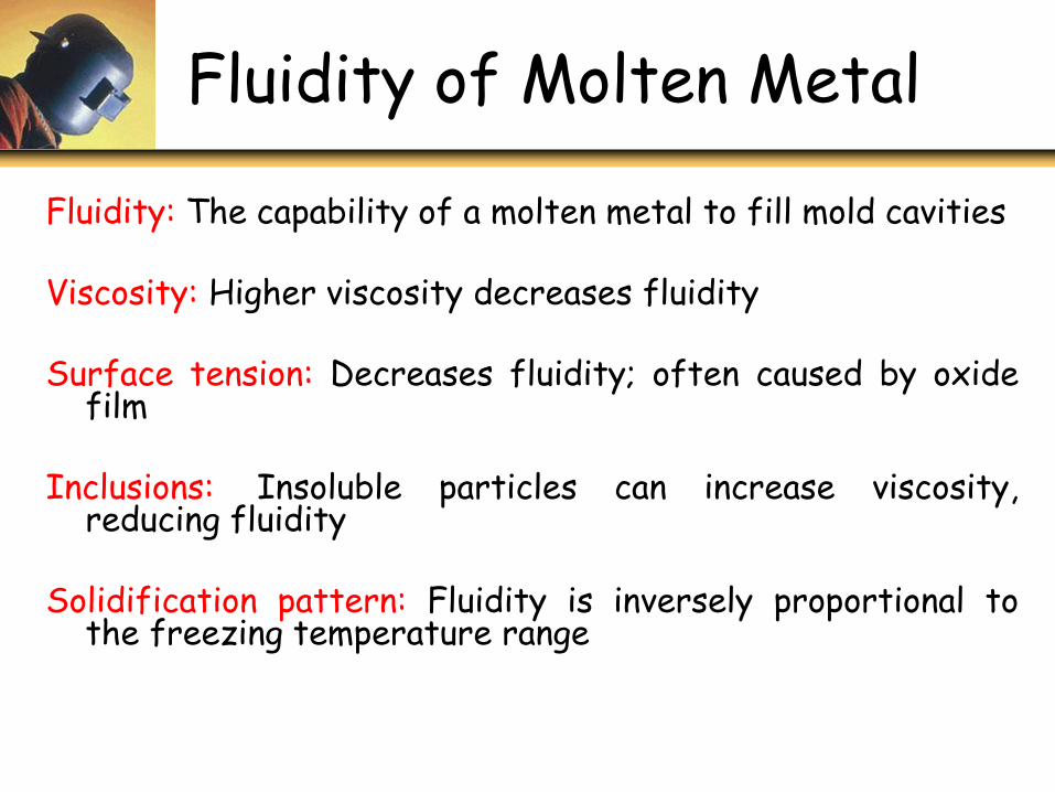
Fluidity of Molten Metal
Fluidity: The capability of a molten metal to fill mold cavities
Viscosity: Higher viscosity decreases fluidity
Surface tension: Decreases fluidity; often caused by oxidefilm
Inclusions: Insoluble particles can increase viscosity,reducing fluidity
Solidification pattern: Fluidity is inversely proportional tothe freezing temperature range
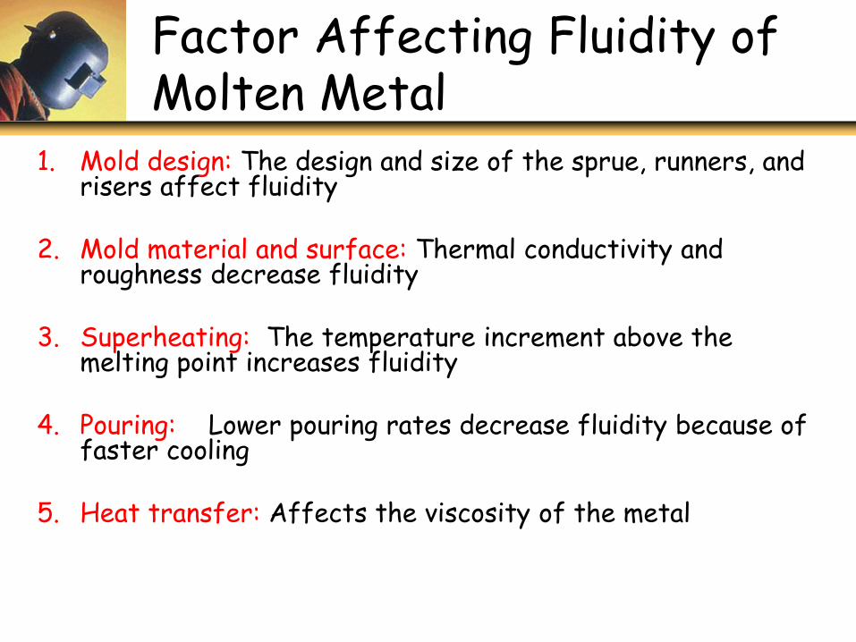
Factor Affecting Fluidity of Molten Metal
1. Mold design: The design and size of the sprue, runners, and risers affect fluidity
2. Mold material and surface: Thermal conductivity and roughness decrease fluidity
3. Superheating: The temperature increment above the melting point increases fluidity
4. Pouring: Lower pouring rates decrease fluidity because of faster cooling
5. Heat transfer: Affects the viscosity of the metal