u3-02 mix pump - kool technologies inc.kooltechnologies.com/pumps-stands-and-accessories/... ·...
TRANSCRIPT

U3-02 Mix PumpManual No. 513557
Owner's/Service Manual


Need Parts or Service?
We stock the parts you need.Our Technicians are factorytrained and are certified in theStoelting Technicare program.
Model No.: _______________________Serial No.: _______________________Purchase Date: ____________________Start-Up Date:____________________
CALLDistributor: _________________________Phone No.: _________________________ (fill in or affix label)


This manual provides basic information about the mix pump and its components. Instructions and suggestions aregiven covering its basic operation and care.
The illustrations and specifications are not binding in detail. We reserve the right to make changes at any time withoutnotice to mix pump or components without incurring any obligation to equip same on mix pump built prior to date ofchange.
DO NOT ATTEMPT to operate the mix pump until instructions and safety precautions in the manual are read completelyand thoroughly understood. The mix pump should be operated only by qualified personnel. If problems develop orquestions arise in connection with the installation, operation, or servicing of the mix pump, contact your local distributoror the company at the following location:
STOELTING, LLC Ph: 920-894-2293502 HWY. 67KIEL, WISCONSIN 53042-1600 Fax: 920-894-7029
INTRODUCTIONU3-02 MIX PUMP - OWNER'S / SERVICE MANUAL


Safety Alert Symbol:This symbol Indicates danger, warning or caution.Attention is required in order to avoid serious personalinjury. The message that follows the symbol containsimportant information about safety.
Signal Word:Signal words are distinctive words used throughoutthis manual that alert the reader to the existence andrelative degree of a hazard.
CAUTIONThe signal word “CAUTION” indicates a potentiallyhazardous situation, which, if not avoided, may resultin minor or moderate injury and equipment/propertydamage.
A Few Words About Safety
Safety Information Read and understand the entire manual beforeoperating or maintaining Stoelting equipment.
This Owner's Manual provides the operator withinformation for the safe operation and maintenance ofStoelting equipment. As with any machine, there arehazards associated with their operation. For thisreason safety is emphasized throughout the manual.To highlight specific safety information, the followingsafety definitions are provided to assist the reader.
The purpose of safety symbols is to attract yourattention to possible dangers. The safety symbols,and their explanations, deserve your careful attentionand understanding. The safety warnings do not bythemselves eliminate any danger. The instructions orwarnings they give are not substitutes for properaccident prevention measures.
If you need to replace a part, use genuine Stoeltingparts with the correct part number or an equivalentpart. We strongly recommend that you do not usereplacement parts of inferior quality.
WARNINGThe signal word “WARNING” indicates a potentiallyhazardous situation, which, if not avoided, may resultin death or serious injury and equipment/propertydamage.
CAUTIONThe signal word “CAUTION” not preceded by the safetyalert symbol indicates a potentially hazardous situa-tion, which, if not avoided, may result in equipment/property damage.
NOTICEThe signal word “NOTICE” indicates information orprocedures that relate directly or indirectly to thesafety or personnel or equipment/property.


TABLE OF CONTENTS
SECTION 1 — INTRODUCTION ............................................................................................................................ 1
1.1 Description ..................................................................................................................................................... 11.2 Specifications ................................................................................................................................................. 1
SECTION 2 — INSTALLATION INSTRUCTIONS ................................................................................................... 3
2.1 Shipment and Transit ..................................................................................................................................... 32.2 National Sanitation Foundation Compliance Requirements ............................................................................ 32.3 Installation ...................................................................................................................................................... 32.4 Mix Pump Check Out ..................................................................................................................................... 5
SECTION 3 — OPERATION INSTRUCTIONS ....................................................................................................... 7
3.1 Safety Precautions ......................................................................................................................................... 73.2 Pump Motor Switch ........................................................................................................................................ 73.3 Operation Of U3 Mix Pump ............................................................................................................................ 73.4 Cleaning ......................................................................................................................................................... 83.5 Disassembly and Inspection of Removable Parts .......................................................................................... 83.6 Sanitizing and Startup .................................................................................................................................... 93.7 Cleaning Mix Lines ......................................................................................................................................... 9
SECTION 4 — MAINTENANCE INSTRUCTIONS ............................................................................................... 11
4.1 Overrun Adjustment ....................................................................................................................................... 114.2 Preventative Maintenance .............................................................................................................................. 11
SECTION 5 — TROUBLESHOOTING ................................................................................................................ 13
SECTION 6 — REPLACEMENT PARTS INFORMATION .................................................................................... 15
6.1 How to Order Replacement Parts ................................................................................................................. 156.2 Parts List and Reference Drawings ............................................................................................................. 15

LIST OF ILLUSTRATIONS
Figure Description Page
1 U3 Pump ................................................................................................................. 1
2 Mix Transfer Line .................................................................................................... 3
A Mix Pump Hose ...................................................................................................... 4
B Pickup Hose ........................................................................................................... 4
C Pickup Hose ........................................................................................................... 4
3 Mix Pump Installation .............................................................................................. 5
D 4-way Tee Connection ............................................................................................. 5
4 Pump Motor Switch ................................................................................................. 7
5 Mix Pump Operation ............................................................................................... 8
6 Removing Parts ...................................................................................................... 8
7 Overrun Adjustment ................................................................................................ 11
8 Reposition Mix Pump Hose..................................................................................... 12
9 Pump Roller Assembly............................................................................................ 12
10 Pump and Decal Assembly ..................................................................................... 15
Exploded Parts Illustrations ..................................................................................... 17-21
Wiring Diagram........................................................................................................ 23

1
1.1 DESCRIPTIONThe Model U3 Remote Mix Pump is specially designed foruse with Stoelting remote pressurized freezers. Used withlarge capacity mix containers located in your bulk storagecooler, the U3 Pump keeps mix handling to a minimum.
Stoelting’s Model U3 Remote Mix Pump performs threeimportant functions with precision and reliability. First, ittransfers a continuous supply of mix from your remotestorage container to the freezing cylinder of your freezer -quickly, conveniently. Second, the U3 Pump preciselyinjects a preset amount of air into the mix, maintainingoverrun to assure maximum profitability. Third, it pressur-izes the freezing cylinder, forcing frozen product throughthe spigot at the rapid dispense rates needed by highvolume locations.
SECTION 1INTRODUCTION
1.2 SPECIFICATIONS
WEIGHT24 lbs. (10.89 kg)
DIMENSIONSWidth: 9-3/4" (24.8 cm)Height: 8-1/2" (21.6 cm)Depth: 10-1/8" (25.7 cm)
ELECTRICAL1 phase, 120 volts. Approximately 1.6 total running amps.Cord and plug attached.
WARRANTYOne year parts.UL, C-UL Approved, NSF Approved
Figure 1 U3 Pump

2

3
2.1 SHIPMENT AND TRANSITThe mix pump has been completely assembled, operatedand inspected at the factory. Upon arrival at the finaldestination, the mix pump must be checked for anydamage that may have occurred during transit.
The mix pump should arrive in satisfactory condition. THECARRIER IS RESPONSIBLE FOR ALL DAMAGE INTRANSIT, WHETHER VISIBLE OR CONCEALED. Do notpay the freight bill until you have checked the equipment.Have the carrier note any visible damage on the freight bill.If concealed damage and/or shortage is found later, advisethe carrier inspector within 10 days and request inspec-tion. The customer must place claim for damages and/orshortages in shipment with the carrier. Stoelting, Inc.cannot make any claims against the carrier.
2.2 NATIONAL SANITATION FOUNDATION COMPLIANCE REQUIREMENTS
In order to comply with "NSF International" (NSF) code #6:
A. This unit (remote pump) must be installed with a“NSF” listed refrigerated mix transfer line. The mixtransfer line must be pitched to cooler, with no sagsor low points, to allow complete drainage (Fig. 2).
B. The product at the mix pump and in transfer linesmust be maintained below 41°F (5°C.)
2.3 INSTALLATIONA. Follow the steps below to install the mix pump in an
upright position on the wall using optional pumpmounting kit. Allow clearance for a mix containerunder pump. See Figure 2.
1. Mount by locating four (4) hole centers on coolerwall using mounting bracket as template.
CAUTIONKNOW THE COOLER'S WALL DESIGN BEFOREDRILLING TO PREVENT PERSONAL INJURY ORPROPERTY DAMAGE.
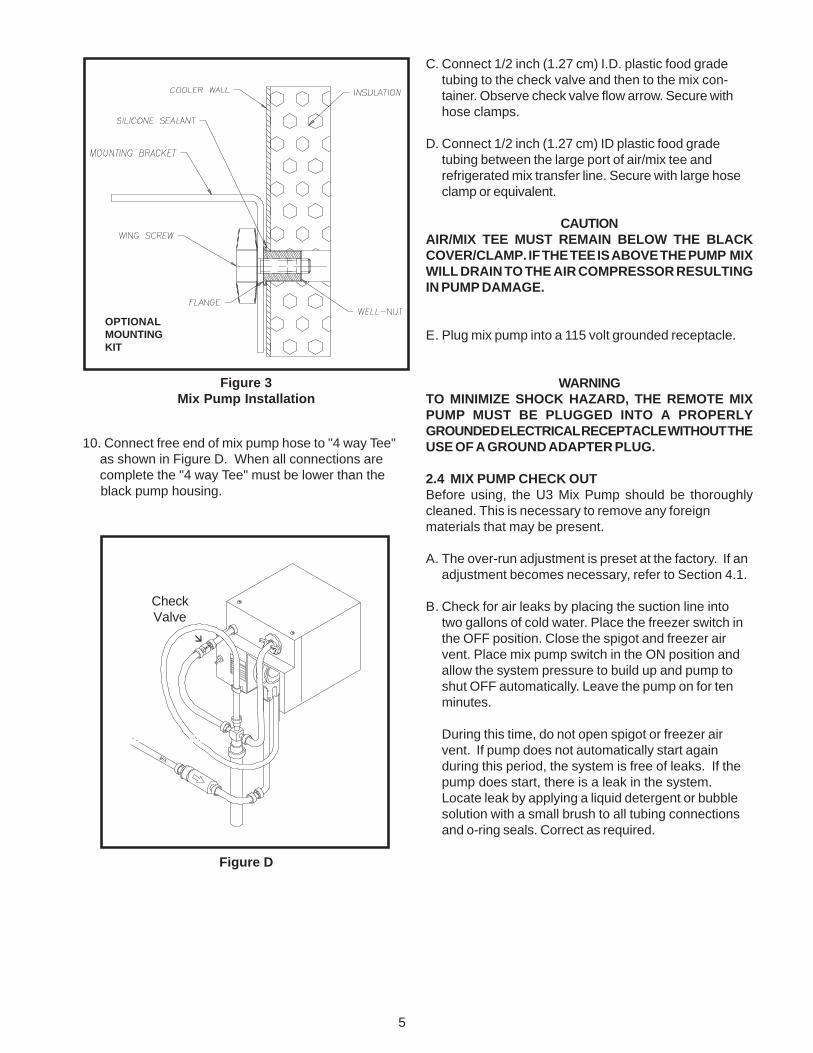
2. Drill four (4) 1/2 inch diameter holes into coolerwall 3/4 inch deep. See Figure 3.
3. Insert well-nut to flange and apply silicone sealantaround outside diameter of flange and cooler wall.
4. Repeat steps 2 & 3 for other located hole centers.
5. Mount bracket to cooler wall with supplied wingscrews. Hand tighten until secure.
6. Thread plastic standoffs (small parts bag) onto allthree pump mounting studs located under thepump until bottomed.
7. Mount pump to bracket with wing nuts. Pump willbe held above the bracket by the standoffs.
SECTION 2INSTALLATION INSTRUCTIONS
Figure 2Mix Transfer Line
COOLER WALL
PUMP
MIXCONTAINER
REFRIGERATIONUNIT FOR MIX LINE
FREEZER
CHECKVALVE
20 FT. MAXIMUM
10 FT. LIFTMAXIMUM

4
B. Mix Pump Hose Installation.
Follow the steps below to install the mix pump hose.
1. Turn pump on.
2. Feed one end of mix pump hose into the entering or pick-up hose side (left) of black cover.
3. Gently push the hose into the black cover until it begins to feed. See Figure A.
Figure A
4. Allow the hose to feed itself thru the pump until 6" remains on the entering side.
5. Turn pump off.
6. Connect mix pump hose to pickup hose adapter using small hose clamp. See Figure B.
CAUTION: DO NOT TWIST MIX PUMP HOSE.
Figure B
Figure C
7. Turn pump on.
8. Gently pull on the discharge hose to help remaining 6"of mix pump hose to feed thru pump until hose adapterprevents further feeding.
9. Turn pump off. See Figure C.
5
10. Connect free end of mix pump hose to "4 way Tee" as shown in Figure D. When all connections are complete the "4 way Tee" must be lower than the black pump housing.
C. Connect 1/2 inch (1.27 cm) I.D. plastic food gradetubing to the check valve and then to the mix con-tainer. Observe check valve flow arrow. Secure withhose clamps.
D. Connect 1/2 inch (1.27 cm) ID plastic food gradetubing between the large port of air/mix tee andrefrigerated mix transfer line. Secure with large hoseclamp or equivalent.
CAUTIONAIR/MIX TEE MUST REMAIN BELOW THE BLACKCOVER/CLAMP. IF THE TEE IS ABOVE THE PUMP MIXWILL DRAIN TO THE AIR COMPRESSOR RESULTINGIN PUMP DAMAGE.
E. Plug mix pump into a 115 volt grounded receptacle.
WARNINGTO MINIMIZE SHOCK HAZARD, THE REMOTE MIXPUMP MUST BE PLUGGED INTO A PROPERLYGROUNDED ELECTRICAL RECEPTACLE WITHOUT THEUSE OF A GROUND ADAPTER PLUG.
2.4 MIX PUMP CHECK OUTBefore using, the U3 Mix Pump should be thoroughlycleaned. This is necessary to remove any foreignmaterials that may be present.
A. The over-run adjustment is preset at the factory. If anadjustment becomes necessary, refer to Section 4.1.
B. Check for air leaks by placing the suction line intotwo gallons of cold water. Place the freezer switch inthe OFF position. Close the spigot and freezer airvent. Place mix pump switch in the ON position andallow the system pressure to build up and pump toshut OFF automatically. Leave the pump on for tenminutes.
During this time, do not open spigot or freezer airvent. If pump does not automatically start againduring this period, the system is free of leaks. If thepump does start, there is a leak in the system.Locate leak by applying a liquid detergent or bubblesolution with a small brush to all tubing connectionsand o-ring seals. Correct as required.
Figure 3Mix Pump Installation
OPTIONALMOUNTINGKIT
Figure D
CHECK VALVE
Check Valve

6

7
3.1 SAFETY PRECAUTIONSDo not attempt to operate the U3 pump until the safetyprecautions and operating instructions in the manual areread completely and thoroughly understood.
Take notice of all warning labels on the U3 pump. Thelabels have been put there to help in maintaining a safeworking environment. The labels are designed to withstandwashing and cleaning. All labels must remain legible forthe life of the mix pump. Warning labels should be checkedperiodically to be sure they have not been removed,painted over, rubbed off, and can be recognized as warninglabels.
If replacement labels are needed, indicate the part number,type of label, location of label, and quantity required. Mailyour name and address to:
STOELTING, LLCATTENTION: Customer Service502 Hwy 67Kiel, Wisconsin 53042
Labels will be furnished and mailed at no charge.
SAFE OPERATION IS NO ACCIDENT; Observe theserules:
A. Know the U3 pump - read and understand theOwner’s Manual.
B. Wear proper clothing - avoid loose fitting garments,and remove watches, rings or jewelry which couldcause a serious accident.
C. Maintain a clean work area - avoid tripping or slippingby cleaning up the area and keeping it clean.
D. Stay alert at all times - know which switch, pushbutton or control you are about to use and what effectit is going to have.
E. Turn all switches to OFF prior to making any adjust-ments.
F. Do not attempt to repair or perform maintenance onthe mix pump until the main electrical power hasbeen disconnected.
G. Do not operate the mix pump if unusual orexcessive noise or vibration occurs.
3.2 PUMP MOTOR SWITCH
The PUMP MOTOR switch (Fig. 4) is located on the mixpump assembly. When the pump motor switch is placedin the ON position, the mix pump motor will be actuated topump mix into the freezer cylinder. When the set pressureis reached, the mix pump will shut off automatically. Whenthe pump motor switch is placed in the OFF position, themix pump will be inoperative.
NOTEThe mix pump motor is equipped with an internaloverload that will “kick-out” when the motor is over-loaded. Consult the trouble shooting section for cor-rective information.The internal overload will auto-matically reset after cooling. If the condition contin-ues, contact a qualified service person.
3.3 OPERATION OF U3 MIX PUMP
SECTION 3OPERATION INSTRUCTIONS
Figure 4Pump Motor Switch
This section describes the operation of the U3 mix pump.
NOTEMix pump hose must be repositioned every 1 -2 weeks. Failure to comply will result in reducedmix pump liquid capacity, dispense stoppage, pop-ping, and possible mix pump hose leakage. Ref. toNote from Section 4.2.
A. Refer to freezer owners manual for the operation ofthe freezer.
B. Mix Operation: The peristaltic mix pump containsone continuous mix pump hose. When looking at theface of the peristaltic mix pump, the left side of thishose is the suction or pickup. The right side of thehose is the discharge. Mix is drawn up the suctionside of the hose and transferred thru the dischargeside to the freezer (Fig. 5).
C. Air Operation: The air compressor operates concur-rently with the peristaltic mix pump. Air enters thruan internal check valve on the piston downstroke.The air is discharged thru a second internal checkvalve, and an external check valve on the pistonupstroke. The air and mix join at the tee and thentravel to the freezer.

8
Figure 5Mix Pump Operation
ROLLER
COVER/CLAMP
4 WAY TEEINLET SIDE
Figure 6Removing Parts
MIX PILLOW
D. Overpressure Relief: Excess pressure is relievedbackwards through the peristaltic mix pump and outthe pickup side of the mix pump hose. This will occuronly if the pressure switch fails to shut off the pumpmotor.
3.4 CLEANINGThe mix pump must be cleaned when changing mix orwhenever the freezer is shut off for an extended period,such as overnight or on nonbusiness days. For sanitaryreasons, mix must not be allowed to remain in thefreezer lines or mix pump when the freezer is not inoperation.
NOTETo clean the freezer, refer to the freezer owner’s manualfor complete cleaning procedures.
1. Place the CLEAN-OFF-ON switch in the cleanposition and agitate 5-10 minutes maximum.
2. Remove suction tube from mix container. Draw offthe mix remaining in freezer barrel.
3. Pump 2 gallons (7.5 liters) of cold potable water thrufreezer until water at spigot is free of mix.
4. Pump 2 gallons (7.5 liters) of warm detergent solutionwater thru freezer. The use of soft water is recom-mended, along with dishwashing detergents such as“Joy,” “Dawn,” or equivalent.
5. Place mix pump switch in OFF position. Open spigotto relieve remaining pressure.
6. Place the CLEAN-OFF-ON switch in the OFF posi-tion.
3.5 DISASSEMBLY AND INSPECTION OF REMOVABLE PARTS
Inspection of removable parts should be made whenevermaintenance is performed or pump requires disassembly.
WARNINGTHE MIX PUMP SWITCH MUST BE IN THE OFFPOSITION WHEN SERVICING OR DISASSEM-BLING PUMP.
CAUTIONNEVER DISCONNECT HOSES FROM FREEZEROR PUMP WITHOUT FIRST OPENING SPIGOTTO RELIEVE PRESSURE.
Check Valve

9
NOTEIf the mix lines or air lines are difficult to remove,soften with a rag soaked in hot water. Hose con-nections may be sprayed with Haynes Sanitary Lu-bricant for ease of removal. Do not loosen or re-move the mix pump cover wingnuts. Maintain themix pump hose in its operational condition.
1. Loosen clamp and remove air hose.
2. Remove the two wing nuts from the pressure controlmanifold and pull out to remove.
3. Loosen clamp and disconnect mix pump hose.Remove the pickup hose, check valve and pickuphose adapter (and bag adapter if applicable) as anassembly from mix container.
4. Completely disassemble both hose assemblies andcheck valve. Place hoses, pressure control manifoldand o-ring, tee, check valve, and pickup hose adapterin mild detergent water and wash thoroughly. Use softbristle brushes to clean inside of fittings. Rinse allparts in clean hot water.
5. Carefully inspect each part for wear or damage.Replace worn or damaged parts.
6. Prepare two gallons (7.5 liters) of sanitizing solutionusing a USDA certified grade sanitizing solution.Sanitize all removed parts, then air dry.
7. Check Hose Service Record decal to determine ifhose reposition or replacement is required at this time(Sec. 4.2).
8. Reassemble both hose assemblies per the diagram(Fig.6). Lubricate the pressure control manifold oringwith sanitary lubricant before assembly. Reconnectassemblies to the pump and discharge hose per thediagram, using the clamps, locking plate washer andwingnuts.
CAUTIONDO NOT FORCE PARTS, THEY FIT TOGETHEREASILY WHEN PROPERLY INSTALLED.
3.6 SANITIZING AND STARTUPFor sanitizing to be effective, it must be performed after themix pump and freezer parts have been cleaned, and justprior to filling the freezer with mix. Sanitizing the nightbefore is not effective.
To sanitize, refer to local sanitary regulations for applicablecodes and recommended disinfecting products and proce-dures. The frequency of cleaning must comply with localhealth regulations. Use a solution containing 100 PPM offree available chlorine. Use “Stera-Sheen Green LabelSanitizer and Cleaner," or others in accordance withHealth Inspection Requirements.
NOTEStoelting, Inc. has found that STERA-SHEENGREEN LABEL SANITIZER AND CLEANER doesan effective job of properly sanitizing and cleaning apump and soft serve freezer. We therefore includea sample with each new freezer. For further infor-mation read the directions on the packet. Otherproducts may be as effective.
CAUTIONPROLONGED CONTACT OF SANITIZER WITH FREEZERMAY CAUSE CORROSION OF STAINLESS STEELPARTS.
In general, sanitizing may be conducted as follows:
1. Prepare two gallons (7.5 liters) of sanitizing solutionfollowing manufacturer’s instruction, and place pumpsuction (inlet) line into solution.
2. Place mix pump switch in ON position.
3. Check for leaks when freezer barrel is first pressur-ized with sanitizing solution.
4. Place freezer CLEAN-OFF-ON switch in CLEANmode (no refrigeration).
5. After five minutes in CLEAN mode, open spigot andpump the remaining sanitizing solution thru thefreezer, close spigot and switch the freezer and pumpto OFF.
6. Place pickup tube into mix bag or container of mixand start the pump.
7. Open spigot, allowing incoming mix to push remain-ing sanitizer out of hoses and freezing cylinder.Close spigot as soon as pure mix begins to come out(after about one pint).
8. Push in the air bleed valve located on the front door(Challenger Series) and allow the mix to come within1/2" of the air bleed valve, then close the valve.
9. Place freezer in the on or freezing position.
3.7 CLEANING MIX LINESThe mix lines must be cleaned and sanitized wheneverchanging mix or whenever the freezer is off for an extendedperiod of time - such as overnight, or nonbusiness days.The mix lines are sufficiently cleaned and sanitized whencleaning and sanitizing the pump and freezer as anassembly.
Once every 2 weeks, if required, perform the followingsteps:

10
A. Mix 2 gallons (7.5 liters) of milkstone remove solutionaccording to the directions on the container and pumpthrough the mix line.
B. Cut a piece of sponge slightly larger than the insidediameter of the mix line. Place the sponge inside themix line and force through with tap water pressure. Agarden hose repair end clamped to the mix line workswell for this purpose.

11
4.1 OVER-RUN ADJUSTMENTThe product when served is a combination of air and mix.Over-run is a measure of the amount of air blended into themix.
Over-run can be expressed in terms of the amount ofweight loss for a given volume. For example, if a pint ofliquid mix weighs 18 ounces and a pint of frozen productwith air added weighs 12 ounces, the over-run is said to be50 percent (18 oz. - 12 oz. = 6 oz., (6 /12) x 100 = 50%.
The over-run can be checked by placing a one pintcontainer on an ice cream scale and zeroing out the scale.Then fill a one pint container with frozen product. Thecontainer should be filled over the top and leveled with astraightedge. The product should not contain any airpockets. When weighed on an ice cream scale, one pintof product should weigh 12 to 13 ounces.
The mix pump has been preset at the factory to produce aproduct with approximately 40% overrun. Because ofdifferences in mix formulation, temperatures and baromet-ric pressure, this figure may vary. It will be necessary forapproximately 2 gallons of mix to be pumped thru thefreezer before changes in the product are noticeable dueto adjustments in overrun.
Overrun is controlled by the length of the air compressorpiston stroke within the piston cylinder. Lengthening thestroke within the cylinder will increase overrun. Con-versely, shortening the stroke will decrease overrun. Toperform an overrun adjustment, refer to the followingprocedure:
A. Turn the mix pump switch to the OFF position andunplug the mix pump from its grounded 115V recep-tacle.
B. Remove the 2 electrical box cover screws and removethe electrical box cover.
C. On air compressor side of pump, locate the long/slender piston rocking arm. The rocking arm down-ward travel is limited by a stationery cam. On theface of the cam there is an overrun setting indicatorplate numbered 3 thru 8 and an adjustment knob(Fig. 7).
D. The overrun setting is indicated by a pointed pin.
E. To adjust overrun, loosen the allenhead screw(located within the center of the adjustment knob)with the 5/32" allen wrench provided. Rotate theadjustment knob counterclockwise to a highernumber for higher overrun, or clockwise to a lowernumber for lower overrun. Each number multiplied by10 represents the overrun percentage (ie: #4 = 40%overrun).
SECTION 4MAINTENANCE INSTRUCTIONS
Figure 7Overrun Adjustment
F. Tighten the allen screw, then place the wrench backin its clip. Replace the electrical box cover andscrews, plug the mix pump into its grounded 115Vreceptacle and turn the mix pump power switch to theON position.
4.2 PREVENTATIVE MAINTENANCETo assure trouble free operation and consistent over-runwhen using the U3 mix pump, we must follow mix hoserepositioning and replacement procedures. The followingis the preventative maintenance schedule:
A. MIX PUMP HOSE REPOSITION (every one or twoweeks.)
NOTEMix pump hose must be repositioned every 1 - 2weeks. Failure to comply will result in reduced mixpump liquid capacity, dispense stoppage, popping,and possible mix pump hose leakage.
1. Run cleaning solution through pump.
2. Turn pump off and if connected to freezer, relieve anypressure by opening the spigot.
3. Grasp the pick-up hose end of the mix pump hosewith one hand and turn the pump on. Pull down on thepick-up hose end until 12 to 14 inches of tubing hasreversed fed through the pump, then turn the pumpoff.
4. Loosen small clamp at the pick-up hose adapter anddisconnect mix pump hose.
5. Cut 7-1/2 inches off the end of the mix pump hose.The height of the pump can be used to measure. SeeFigure 8.
OVERRUNADJUSTMENT

12
6. Reconnect mix pump hose to adapter.
7. Turn pump on.
8. Gently pull on the discharge hose to help remaining6" of mix pump hose to feed thru pump until hoseadapter prevents further feeding.
9. Turn pump OFF and pump will be ready for normaloperation.
NOTEEach hose is long enough for 3 repositions beforereplacement is required. Record each event on HoseService Record decal.
B. MIX PUMP HOSE REPLACEMENT
NOTEMix pump hose must be replaced when tubing can-not be further repositioned (every four to eightweeks). Failure to comply will result in hose failureand possible pump damage.
1. Run cleaning solution through pump.
2. Turn pump off and if connected to freezer relieve anypressure by opening the spigot.
WARNINGTHE MIX PUMP SWITCH MUST BE IN THE "OFF"POSITION WHEN SERVICING OR CLEANING PUMP.
CAUTIONNEVER DISCONNECT HOSES FROM FREEZER ORPUMP WITHOUT FIRST OPENING SPIGOT TO RE-LIEVE PRESSURE.
3. Disconnect mix pump hose at each end.
4. Grasp the discharge hose end with one hand and turnthe pump on. Pull down on the hose until all of theremaining hose is removed from the pump.
Pressures for Stoelting Freezers: Cut-out 24# ±3 PSIGFor Duke Freezers: Cut-out 30# ±3 PSIG
19
ROLLER
DISCHARGE SIDE
COVER/CLAMP
PICK UPSIDE
CUT LINEMEASUREMENT
MIX PILLOW
Figure 8. Reposition Mix Pump Hose5. Turn pump roller assembly so one roller is at 6:00.
4 WAY TEE
20
6. Use a brush that fits in the opening and brush up anddown, first with detergent water and then clear water.
7. Connect mix pump hose to pick-up hose adapter,using small clamp.
8. Insert free end of hose into the pick-up (suction side)hose side of the black cover. Gently push the hoseinto the black cover until it begins to self-feed. Allowthe hose to feed itself through the pump until the mixpump hose comes out the discharge side. Then gentlypull on the discharge hose to help remaining mixpump hose feed thru pump until hose adapter preventsfurther feeding, then turn pump off.
NOTERemove cover clamp from pump on a monthly basisto clean and check for wear. (Cover clamp & rollerbearings) Clean parts with soap and water and re-assemble.
9. Reconnect mix pump hose to T using small clamp.Pump is now ready to sanitize.
Figure 9. Pump Roller Assembly
Roller
Cover/Clamp
InletSide
DischargeSide
Cover/Clamp
Discharge SideInletSide
Roller

13
SECTION 5TROUBLESHOOTING
1. PUMP MOTOR DOES NOT RUNPower to pump is off. Supply power to pump.Low voltage. Check for low voltage.Mix pump hose jammed inside black cover/clamp. Disconnect pump from power source. Remove four
cover/clamp thumb screws. Separate cover/clamp halvesand remove outer half. Remove jammed hose. Re-installcover/clamp and tighten four thumb screws securely.Allow motor thermal overload to reset. See Sec. 4.2 forhose replacement. Do not use jammed portion of hose.
Pump motor overloaded. Allow internal thermal overload to reset; determineoverload cause and repair.
Pressure switch on pump is defective. Check mechanical operation and continuity of pressureswitch.
Defective motor/capacitor Check motor amperage draw and/or capacitor. Replacemotor or capacitor.
Defective toggle switch. Check continuity; repair or replace.2. PUMP OPERATES BUT CYLINDER WILL NOT FILLNOTE 1: A PROPERLY WORKING PUMP WILL FILL AN 8 OZ. CUP WITH MIX IN ABOUT 9 SECONDS.NOTE 2: IMMEDIATELY AFTER A "BAG CHANGE" THE PUMP MAY BE UNABLE TO RE-ESTABLISH IT'S PRIME WITHTHE SYSTEM AT OPERATING PRESSURE. IN THIS CASE, TURN THE PUMP OFF. DRAW 2-3 PINTS TO REDUCESYSTEM PRESSURE TO ZERO. TURN PUMP ON. PURGE REMAINING AIR IN MIX BAG AND PICK-UP HOSE.
IMPORTANT: Before connecting the pick-up hose to the mix bag, purge the mix bag of air to the extentpossible.Out of Mix. Replenish mix supply.MIx pump hose kinked inside black cover/clamp. Follow mix pump hose jammed repair. (See #1 above.)Hoses assembled incorrectly. Refer to diagram for correct hose connections.Mix pump hose service life is exceeded. Reposition/replace mix pump hose. See Sec. 4.2.Mix pump hose not connected to freezer. Connect mix pump hose to freezer.Ice crystals in mix. Completely thaw mix prior to use.Mix bag drawn against adapter. Assure bag is clear of pick-up tube.Foreign objects in mix. Clear blockage. Use fresh mix.Check valve is backwards. Observe flow arrow for proper orientation.3. OVERRUN TOO LOW OR NO OVERRUNOverrun setting too low. Increase overrun setting.Air leak. Tighten all hose clamps.Air compressor not pumping air. Contact local Stoelting Distributor.4. OVERRUN TOO HIGHMix pump hose service life is exceeded. Reposition/replace mix pump hose.Out of mix. Replenish mix supply.Overrun setting too high. Decrease overrun setting.Pick-up leg of mix pump hose is collapsing. See Section 4.2.NOTE: ALSO SEE "2" ABOVE.

14
5. REPLACEMENT MIX PUMP HOSE WON'T FEED THROUGH PUMPFeeding hose into discharge hole of mix pump cover. Feed hose into pick-up side of cover.Hose ends not cut squarely. Carefully cut hose end off squarely (no tails).Force feeding too quickly. Gently and slowly assist feeding of hose up into pick-up
hose side of cover.Pump motor not running. Turn on motor switch. Also see Item 1 above.6. AIR EXITING MIX PICK-UP HOSEPickup tube check valve missing. Contact local Stoelting Distributor.7. DISPENSED PRODUCT AIR "POPS"Overrun setting too high. Reposition/replace mix pump hose.Mix pump hose service life is exceeded. Reposition/replace mix pump hose.Overdrawing the freezer's capacity. Reduce dispense rate.Recent "mix-out" condition. Open spigot fully and allow excess air to "belch" out.NOTE: ALSO SEE 2 & 4 ABOVE.8. MIX LEAKAGE FROM PUMPCAUTION: To prevent mix pump damage from dried mix deposits, immediately disassemble and cleanpump.Mix pump hose service life is exceeded. Remove mix pump hose. Disconnect pump from power
source. Remove mix pump cover/clamp. THOROUGHLYrinse three squeeze rollers using a spray bottle filled withhot water. Thoroughly clean all mix from pump. See Sec.4.2 for hose replacement. Lubricate squeeze rollerbearings, see Item #10 below.
9. PUMP HAS POOR CAPACITYLift and run limits are exceeded. Pump is limited to 10' lift, 20' run.NOTE: Also see 2, 4, 6 & 7.10. PUMP IS NOISY/SQUEAKINGNOTE: THE ACTION OF THE AIR COMPRESSOR ROCKING ARM CREATES A REPETITIVE CLICKING SOUND DURINGOPERATION. THIS IS NORMAL.NOTE: THE PERISTALTIC MIX PUMP HAS THREE SQUEEZE ROLLERS WHICH USE SELF LUBRICATING BEARINGS. IFSQUEAKING EXISTS WITH THE MIX PUMP HOSE IN PLACE, AND STOPS WITH THE HOSE REMOVED, THE SQUEEZEROLLER BEARINGS CAN BE LUBRICATED USING A SILICONE BASED SPRAY. REMOVE THE MIX PUMP HOSE.DISCONNECT PUMP FROM ELECTRICAL POWER. REMOVE FOUR COVER/CLAMP THUMBSCREWS. REMOVE ENTIRECOVER/CLAMP AS ONE UNIT. SPRAY SILICONE BASED LUBRICANT ON EACH END OF EACH SQUEEZE ROLLER.SPIN ROLLERS TO WORK LUBRICANT INTO BEARINGS. REPEAT AS NEEDED.
CAUTION: DO NOT USE CLEANING/DISSOLVING TYPE LUBRICANTS LIKE WD-40. THESE LUBRICANTSARE NOT BEARING FRIENDLY AND WILL ACCELERATE BEARING WEAR.11. MIX IN AIR HOSESAir/mix tee above black cover/clamp. Air/mix tee must be below black cover/clamp.Air leak. Tighten all hose clamps.Mix hose on wrong air/mix tee fitting. Refer to diagram for correct hose connections.Pressure control manifold o-ring leak. Check o-ring and manifold; replace as required.
15
SECTION 6REPLACEMENT PARTS INFORMATION
6.1 HOW TO ORDER REPLACEMENT PARTSTo assure the receipt of the proper replacement parts,supply your dealer, distributor or the company with thefollowing information:
A. Model number of equipment.
B. Serial number of Model. (Stamped on nameplate).
C. Part number, part name, and quantity needed. Manypart names and numbers are listed in this manual.
NOTEMinimum Billing is $50.00 Net.
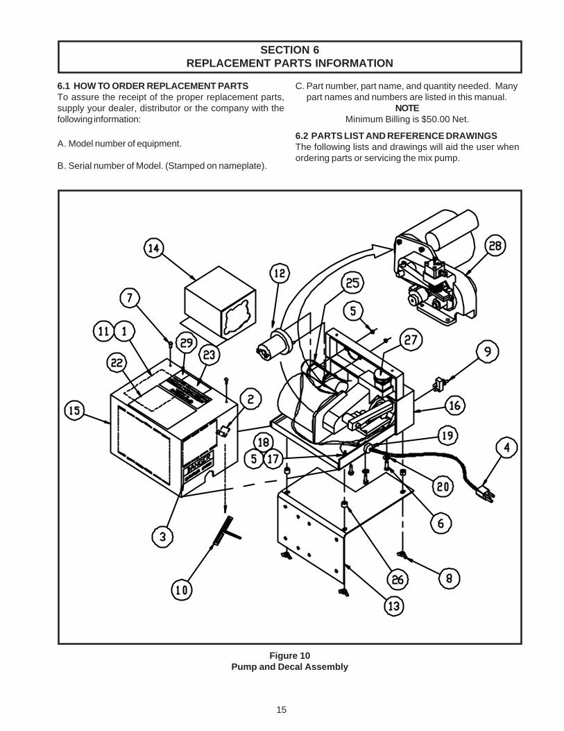
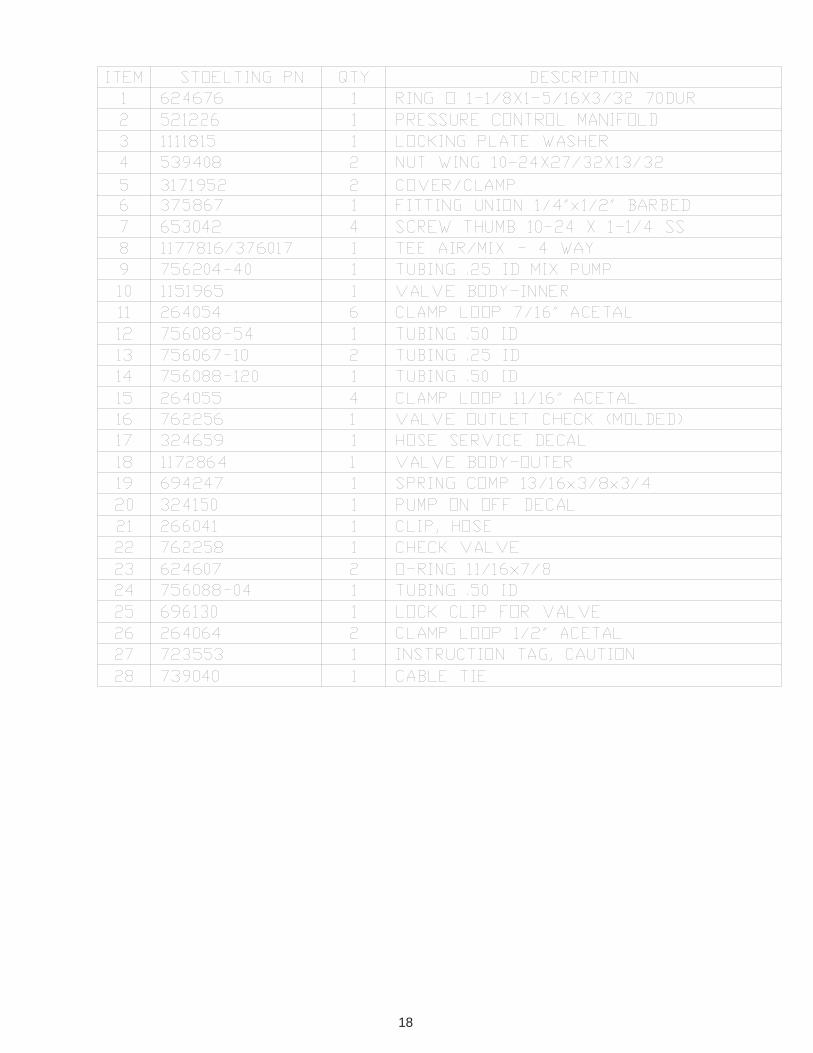
6.2 PARTS LIST AND REFERENCE DRAWINGSThe following lists and drawings will aid the user whenordering parts or servicing the mix pump.
Figure 10Pump and Decal Assembly

16
Pump and Decal Assembly Parts List
ITEM STOELTING P/N QTY. DESCRIPTION
1 130000 1 Bag, Envelope Front Loading2 266018 1 Clip Adhesive Backed "J"3 324105 1 Decal Caution - Elect. Shock4 430022 1 Harness Cord 6.50 Ft.5 538296 3 Nut Hex #10-24 x 3/8 SS6 644116 3 Screw Cap 1/4-20 x 3/4 Hx Hd7 647512 2 Screw Mach 8-32 x 3/8 Pan Hd8 539419 3 Nut Wing 1/4-209 718532 1 Switch Toggle 10 Amp 250V10 778027 1 Wrench Allen 5/3211 1995611 1 Wiring Diagram U3 Pump12 717917-SV 1 Switch Pressure (Stoelting)12 717919-SV 1 Switch Pressure (Duke)13 3170824 1 Mounting Bracket14 3171850 1 Splash Guard15 4177692 1 Pump Box Cover16 4177691 1 Pump Box17 647667 1 Screw Mach 10-24 x 1/2 Rd Hd18 766950 1 Washer Shakeproof #1019 223162 1 Bushing Strain Relief20 766066 3 Washer Lock 1/4-2021 208467 1 Brush (Not Shown)22 324509 1 Cleaning Decal23 2171853 1 Model ID Plate2425 1171960 1 Capacitor, Motor Start26 692225 3 Spacer, Nylon .5 OD, 1/4-2027 1171958 1 Air Filter28 4171953 1 Main Pump Assembly29 324023 1 Decal NSF

17
OPTIONAL MOUNTING KIT
SEE SERVICE REFERENCE, PAGE 19
18

19

20

21

22

23


WARRANTYSOFT SERVE / SHAKE FREEZERS
1. Scope: Stoelting, LLC warrants to the first user (the “Buyer”) that the freezer cylinders, hoppers, compressors, drive motors,
speed reducers, auger and auger flights of Stoelting soft serve / shake freezers will be free from defects in materialsand workmanship under normal use and proper maintenance appearing within five (5) years, and that all othercomponents of such equipment manufactured by Stoelting will be free from defects in material and workmanshipunder normal use and proper maintenance appearing within twelve (12) months after the date that such equipment isoriginally installed.
2. Disclaimer of Other Warranties:
THIS WARRANTY IS EXCLUSIVE; AND STOELTING HEREBY DISCLAIMS ANY IMPLIED WAR-RANTY OF MERCHANTABILITY OR FITNESS FOR PARTICULAR PURPOSE.
3. Remedies:Stoelting’s sole obligations, and Buyer’s sole remedies, for any breach of this warranty shall be the repair or (atStoelting’s option) replacement of the affected component at Stoelting’s plant in Kiel, Wisconsin, or (again, atStoelting’s option) refund of the purchase price of the affected equipment, and, during the first twelve (12) months ofthe warranty period, deinstallation/reinstallation of the affected component from/into the equipment. Those obliga-tions/remedies are subject to the conditions that Buyer (a) signs and returns to Stoelting, upon installation, theChecklist/Warranty Registration Card for the affected equipment, (b) gives Stoelting prompt written notice of anyclaimed breach of warranty within the applicable warranty period, and (c) delivers the affected equipment to Stoeltingor its designated service location, in its original packaging/crating, also within that period. Buyer shall bear the costand risk of shipping to and from Stoelting’s plant or designated service location.
4. Exclusions and Limitations:This warranty does not extend to parts, sometimes called “wear parts”, which are generally expected to deteriorateand to require replacement as equipment is used, including as examples but not intended to be limited to o-rings,auger seals, auger support bushings and drive belts. All such parts are sold
AS IS.
Further, Stoelting shall not be responsible to provide any remedy under this warranty with respect to any componentthat fails by reason of negligence, abnormal use, misuse or abuse, use with parts or equipment not manufactured orsupplied by Stoelting, or damage in transit.
THE REMEDIES SET FORTH IN THIS WARRANTY SHALL BE THE SOLE LIABILITY STOELTINGAND THE EXCLUSIVE REMEDY OF BUYER WITH RESPECT TO EQUIPMENT SUPPLIED BYSTOELTING; AND IN NO EVENT SHALL STOELTING BE LIABLE FOR ANY INCIDENTAL ORCONSEQUENTIAL DAMAGES, WHETHER FOR BREACH OF WARRANTY OR OTHER CON-TRACT BREACH, NEGLIGENCE OR OTHER TORT, OR ON ANY STRICT LIABILITY THEORY.