u13: co-simulation of heavy truck tire dynamics and
TRANSCRIPT

U13: Co-Simulation of Heavy Truck Tire Dynamics
and Electronic Stability Control Systems (Phase A)
This project was funded by the NTRCI University Transportation Center under a grant
from the U.S. Department of Transportation Research and Innovative Technology
Administration (#DTRT06G-0043)
The contents of this report reflect the views of the authors, who are responsible for the
facts and the accuracy of the information presented herein. This document is
disseminated under the sponsorship of the Department of Transportation University
Transportation Centers Program, in the interest of information exchange. The U.S.
Government assumes no liability for the contents or use thereof.
Mr. John Limroth, Clemson University International Center for Automotive Research
Dr. Thomas Kurfess, Clemson University International Center for Automotive Research
Dr. E. Harry Law, Clemson University International Center for Automotive Research
July, 2009

1. Report No.
2. Government Accession No.
3. Recipient's Catalog No.
4. Title and Subtitle
U13: Co-Simulation of Heavy Truck Tire Dynamics and Electronic Stability
Control Systems (Phase A)
5. Report Date
July 2009
6. Performing Organization Code
7. Author(s)
Mr. John Limroth, Dr. Thomas Kurfess and Dr. E Harry Law – Clemson
University International Center for Automotive Research
8. Performing Organization Report No.
9. Performing Organization Name and Address
National Transportation Research Center, Inc.
University Transportation Center
2360 Cherahala Blvd.
Knoxville, TN 37932
10. Work Unit No. (TRAIS)
11. Contract or Grant No.
DTRT06G-0043
12. Sponsoring Agency Name and Address
U.S. Department of Transportation
Research and Innovative Technology Administration
1200 New Jersey Avenue, SE
Washington, DC 20590
13. Type of Report and Period Covered
Final Report March 2009 – July 2009
14. Sponsoring Agency Code
RITA 15. Supplementary Notes
16. Abstract
Electronic stability control (ESC) systems have been proven to be an effective means of preventing instability and loss of control on both
passenger vehicles and heavy trucks. In addition, roll stability algorithms are an effective means of reducing the risk of rollover on heavy
trucks with their relatively high centers of gravity. Stability control systems are so effective that the U.S. government has mandated their
inclusion on all new passenger vehicles by September 2011, and similar legislation is anticipated soon for heavy trucks. The goal of this
research project is to produce a software co-simulation of an articulated tractor-trailer model together with an ESC algorithm.
Such a simulation platform will enable the investigation of truck performance both with and without stability control and the sensitivity of
vehicle performance to changes in vehicle parameters. The simulations will be used to conduct experiments to determine particular vehicle
configurations and parameters that result in improved vehicle stability and dynamic performance. In addition the simulation platform will
provide a means to investigate advanced stability control algorithms, such as algorithms that automatically adapt to changes in vehicle
parameters such as trailer load configurations. The co-simulation may be a Hardware-In-the-Loop (HIL) simulation system utilizing a
commercial ESC Electronic Control Unit (ECU) or pure software co-simulation with an algorithm representative of a commercial ESC
system.
17. Key Word
Co-Simulation, Heavy Truck Tire Dynamics, Electronic Stability
Control System (ESC), vehicle stability, hardware-in-the-loop
18. Distribution Statement
No restrictions
19. Security Classif. (of this report)
Unclassified 20. Security Classif. (of this page)
Unclassified 21. No. of Pages
69 22. Price

ii

iii
Table of Contents
EXECUTIVE SUMMARY .......................................................................................................... 1
BACKGROUND ...................................................................................................................................... 1
BRIEF OVERVIEW ................................................................................................................................ 1
RESEARCH TEAM ................................................................................................................................. 2
ESC HIL SIMULATION INVESTIGATION ......................................................................................... 2
ESC SOFTWARE CO-SIMULATION RESULTS ................................................................................. 4
TRACK TESTING PRELIMINARY RESULTS .................................................................................... 6
FUTURE PROGRAM EFFORTS ............................................................................................................ 9
CHAPTER 1 – GENERAL OVERVIEW ................................................................................ 11
BACKGROUND .................................................................................................................................... 11
PROJECT TEAM ................................................................................................................................... 12
MARC Roles and Responsibilities ..................................................................................................... 12
Clemson University Roles and Responsibilities................................................................................. 12
National Instruments Roles and Responsibilities ............................................................................... 12
PROJECT DESCRIPTION AND OBJECTIVES .................................................................................. 12
LITERATURE REVIEW ....................................................................................................................... 13
CHAPTER 2 – ESC HIL SIMULATION INVESTIGATION ............................................... 15
HIL PROJECT TASKS .......................................................................................................................... 15
Simulation Model Development ........................................................................................................ 15
ESC Control Algorithm Development ............................................................................................... 15
Integration of Michelin Tire Models .................................................................................................. 15
ESC Hardware Acquisition ................................................................................................................ 16
HIL Hardware Specification .............................................................................................................. 16
HIL Hardware Acquisition ................................................................................................................. 17
HIL ECU SENSOR AND ACTUATOR INTEGRATION .................................................................... 18
INFORMATION REQUIRED OF ECU SUPPLIER............................................................................. 19
ALTERNATIVE PROJECT PLAN: TRUCK/ESC CO-SIMULATION .............................................. 19
CHAPTER 3 – ESC SOFTWARE CO-SIMULATION .......................................................... 21
SOFTWARE CO-SIMULATION SYSTEM ......................................................................................... 21
YAW STABILITY CONTROL ............................................................................................................. 21
Linear Model Development ................................................................................................................ 21
Yaw Stability Control Algorithm ....................................................................................................... 33
CHAPTER 4 - TRACK TESTING ........................................................................................... 37
SLOWLY INCREASING RAMP STEER MANEUVER ..................................................................... 38
STEP STEER MANEUVER .................................................................................................................. 39
LANE CHANGE MANEUVERS .......................................................................................................... 41
Design of Open-Loop Lane Change Maneuver .................................................................................. 41
Dry Lane Change ............................................................................................................................... 42
Wet Lane Change ............................................................................................................................... 45
Comparison of Vehicle States on Wet and Dry Maneuvers ............................................................... 48

iv
CHAPTER 5 – CONCLUSION ................................................................................................. 53
CHAPTER 6 - REFERENCES .................................................................................................. 55
APPENDIX A ............................................................................................................................ A-1
LITERATURE REVIEW ........................................................................................................ A-1
ELECTRONIC STABILITY CONTROL ALGORITHMS ................................................................. A-1
ESC for Passenger Vehicles ............................................................................................................. A-1
ESC for Articulated Heavy Trucks .................................................................................................. A-3
ARTICULATED TRUCK MODELS FOR HANDLING SIMULATION .......................................... A-5
Analytical Truck Models .................................................................................................................. A-6
Commercial Truck Models ............................................................................................................... A-7

v
List of Figures
Figure 1. Diagram. HIL System Components. ............................................................................... 3
Figure 2. Diagram. ESC Co-Simulation System. ........................................................................... 4
Figure 3. Diagram. ESC Control Strategy. ..................................................................................... 5
Figure 4. Photograph. HIL Rack and Equipment. ........................................................................ 18
Figure 5. Graphs. Step Steer Model Response, 100 kph (a). ........................................................ 23
Figure 6. Graphs. Step Steer Model Response, 100 kph (b). ........................................................ 24
Figure 7. Graphs. Simplified TruckSim® Model Investigation, 100 kph (a). ............................... 26
Figure 8. Graphs. Simplified TruckSim® Model Investigation, 100 kph (b). ............................... 27
Figure 9. Graphs. Modified Linear Tractor/Semi-Trailer Model, 100 kph (a). ............................ 31
Figure 10. Graphs. Modified Linear Tractor/Semi-Trailer Model, 100 kph (b). .......................... 32
Figure 11. Graphs. ESC System Co-Simulation on Low Friction Surface, 100 kph (a). ............. 34
Figure 12. Graphs. ESC System Co-Simulation on Low Friction Surface, 100 kph (b). ............. 35
Figure 13. Graph. Slowly Increasing Steer Test RSC Intervention. ............................................. 38
Figure 14. Graph. Slowly Increasing Steer Test Wheel-End Brake Pressures. ............................ 39
Figure 15. Graph. Step Steer Test RSC Intervention. ................................................................... 40
Figure 16. Graph. Step Steer Test Tractor (Red) and Trailer (Blue) Lateral Acceleration. ......... 40
Figure 17. Graph. Step Steer Test Wheel-End Brake Pressures. .................................................. 41
Figure 18. Graph. Double Lane Change Open-Loop Steering Profile. ........................................ 42
Figure 19. Graph. Dry Double Lane Change Ground Track. ....................................................... 43
Figure 20. Graph. Dry Lane Change High CG Test RSC Intervention. ....................................... 43
Figure 21. Graph. Dry Lane Change High CG Test Wheel-End Brake Pressures. ...................... 44
Figure 22. Graph. Dry Lane Change Low CG Test RSC Intervention. ........................................ 45
Figure 23. Graph. Dry Lane Change Low CG Test Wheel-End Brake Pressures. ....................... 45
Figure 24. Graph. Wet Lane Change High CG Test RSC and YSC Intervention. ....................... 46
Figure 25. Graph. Wet Lane Change Low CG Test Wheel-End Brake Pressures........................ 46
Figure 26. Graph. Wet Lane Change High CG Test Tractor States and YSC Intervention. ........ 47
Figure 27. Graph. Dry and Wet Lane Change Steering Input Comparison. ................................. 48
Figure 28. Graph. Dry and Wet Lane Change Vehicle Speed Comparison. ................................ 49
Figure 29. Graph. Dry and Wet Lane Change Tractor Yaw Rate Comparison. ........................... 49
Figure 30. Graph. Dry and Wet Lane Change Tractor Lateral Acceleration Comparison. .......... 50
Figure 31. Graph. Dry and Wet Lane Change Trailer Articulation Angle Comparison. .............. 50
Figure 32. Graph. Dry and Wet Lane Change Trailer Lateral Acceleration Comparison. ........... 50
Figure 33. Graph. Dry and Wet Lane Change Trailer Lateral Velocity Comparison. .................. 51
Figure A- 1. Diagram. Basic ESC High-Level Control Structure. ............................................. A-2
Figure A- 2. Illustration. Jackknife (Oversteer) Mitigation [23]. ............................................... A-4
Figure A- 3. Illustration. Rollover Condition [23]. ..................................................................... A-4
Figure A- 4. Illustration. Rollover Mitigation [23]. .................................................................... A-5

vi
List of Tables
Table 1. Specified National Instruments Hardware and Software. ............................................... 17
Table 2. Track Testing Maneuvers. .............................................................................................. 37
List of Equations
Equation 1. Tractor and Semi-Trailer Lateral Accelerations. ....................................................... 22
Equation 2. Axle Linear Roll Steer Model. .................................................................................. 28
Equation 3. Quasi-Steady State Roll Model. ................................................................................ 29
Equation 4. Linear Lateral Force Compliance Steer Model. ........................................................ 29
Equation 5. Lateral Force Model. ................................................................................................. 30
Equation 6. Effective Cornering Stiffness Due to Lateral Force Compliance. ............................. 30
Equation 7. Effective Aligning Stiffness Due to Lateral Force Compliance. ............................... 30
Equation 8. Effective Cornering Stiffness Due to Aligning Moment Compliance. ..................... 30
Equation 9. Effective Aligning Stiffness Due to Lateral Force Compliance. ............................... 30

1
Executive Summary
Background
The Co-Simulation of Heavy Truck Tire Dynamics and Electronic Stability Control System
project is a research effort conducted by the National Transportation Research Center, Inc.,
University Transportation Center (NTRCI) in partnership with Clemson University International
Center for Automotive Research (CU-ICAR), Michelin Americas Research Company (MARC),
and National Instruments (NI). This research is one of the projects conducted by the NTRCI in
its role as a University Transportation Center (UTC) for the Research and Innovative
Technology Administration (RITA), an agency within the Department of Transportation (DOT).
Brief Overview
The overall objectives of this research were to:
Determine performance of the truck ESC system and validate against measured test track
data.
Understand the fundamental operation of the ESC system with respect to vehicle
dynamics
Determine the robustness of the ESC system with respect to vehicle configurations and
various vehicle parameters
Study potential improvements to vehicle stability and/or dynamic performance with the
ESC system active due to changes in vehicle parameters
Investigate further improvements in stability control and system identification algorithm
performance through closed-loop simulation with vehicle models
This project entailed the following activities:
1. A review of literature relevant to the operation of heavy truck ESC systems
2. Investigation of a Hardware-In-the-Loop (HIL) simulation system for truck/ESC system
co-simulation
3. Investigation of an offline software co-simulation system
4. Track testing of a tractor/semi-trailer coordinated with the Heavy Truck Rollover
Characterization project
5. Initial investigation of the track testing results for ESC co-simulation system validation
A review of relevant literature was conducted to understand the state-of-the-art of heavy truck
electronic stability control algorithms. A review of passenger car ESC algorithms was conducted
to understand the fundamental operation of these systems since adoption of ESC in the passenger
car market preceded that of the heavy truck market. In addition, a review of the relevant
literature on ESC and roll control systems for articulated heavy trucks was conducted.

2
Since a dynamic model of the articulated truck lateral handling was found to serve as the basis
for determining desired vehicle behavior in ESC systems, a survey of low-order models suitable
for processing on an ESC embedded controller was conducted. In addition, high-fidelity
commercial tools capable of simulating tractor/semi-trailer systems such as TruckSim® and
SIMPACK® were reviewed.
Research Team
Clemson was the overall lead on Phase A of this research, with significant engineering support
provided by Michelin. Clemson led all tasks and deliverables, including the development of the
co-simulation system, evaluation of track testing results, and all project reporting. Michelin
served as the primary industry technical lead and provided significant engineering support,
primarily in the development of the tractor model and flatbed trailer model used for initial ESC
co-simulation development. National Instruments supplied real-time hardware for the HIL test
system, as well as LabVIEW™
software used for modeling the ESC control algorithm and co-
simulating with the TruckSim® vehicle model. National Instruments also provided direct
financial support to the project.
In addition to these tasks, Clemson and Michelin were both heavily involved in the planning and
execution of the tractor/semi-trailer track testing and data analysis. This track testing was a
combined effort of both this ESC co-simulation project Phase A (Project U13) and the Heavy
Truck Rollover Characterization project (HTRC) Phase B (Project U19). Clemson helped define
test maneuvers and instrumentation that yielded useful data for analysis in both projects.
Michelin and other members of the HTRC project also contributed to all phases of planning,
execution, and data analysis of the track testing.
ESC HIL Simulation Investigation
The requirements for a hardware-in-the-loop simulation system were investigated and deemed to
be infeasible without direct support of the ESC electronic control unit (ECU) supplier. The
envisioned system would use the ECU connected to a National Instruments Real-Time PXI
system running a TruckSim® model of the tractor/semi-trailer combination vehicle. Such an HIL
simulator could be used to simulate and investigate the performance of the truck equipped with
ESC without the need for expensive and time-consuming track time. A conceptual view of the
HIL simulation system is shown in Figure 1.

3
Truck model on real-
time computer
ESC ECU
(Bendix)
Simulated sensor
signals
Actuator signals
Figure 1. Diagram. HIL System Components.
Investigation of the available information on input/output signals to the ECU resulted in the
determination that insufficient details of the ECU operation were available for integration into an
HIL system. This included unpublished requirements of the sensors/actuators for diagnostics
purposes and proprietary communication buses used in the system. The initial project proposal
included engaging the ESC ECU supplier, Bendix Commercial Vehicle Systems, as a partner in
the project. However, as Bendix involvement occurred very late in the project timeline, the
project focus was shifted away from an HIL simulation system and instead focused on a software
co-simulation system.
The following is a list of specific information that would be required from the ECU supplier for
the development of an HIL system:
Details of CAN bus communication with Yaw Angle (YAS) and Steer Angle (SAS)
sensor packs
Details of powertrain J1939 bus communication (which signals, and when?)
Sensor/actuator inductance/resistance matching for diagnostics (e.g. valve “chuff” test)
Specific hardware needs for HIL system
o Valves absolutely required for HIL?
o Additional sensors or hardware?
Need to simulate Power Line Carrier (PLC) signal for trailer ECU?
Ultimately due to the timing of the discussions with Bendix and the lack of externally available
information, the decision was made to put the HIL system development on hold.

4
ESC Software Co-Simulation Results
Due to the lack of available information required for the implementation of an HIL simulation
system during Phase A of the project, a pure software co-simulation strategy was pursued. In
this case the vehicle model is not run in real-time on dedicated hardware, but instead is simulated
on a standard desktop PC. However, a second simulation environment is used to model the
behavior of the ESC control algorithm. For this project, LabVIEW™
was used to implement an
ESC algorithm that is representative of those found in the available literature. LabVIEW™
and
TruckSim® are used together to “co-simulate” the complete vehicle with ESC system.
Information must be exchanged at each simulation timestep between the two tools to ensure that
the complete system is accurately simulated. A schematic view of the software co-simulation
system is shown in Figure 2.
Figure 2. Diagram. ESC Co-Simulation System.
Heavy truck ESC systems found in the literature typically implement a state feedback control
scheme with a linear vehicle model used to determine “desired” states of the vehicle. A
schematic view of the control strategy used in the co-simulation system is provided in Figure 3.
A critical component of the algorithm is the use of a linear dynamic model to determine the
desired vehicle states based on vehicle speed and steering input. The model is the “articulated
bicycle” handling model commonly found in the literature with the following states: tractor
lateral velocity, tractor yaw rate, trailer relative articulation angle and articulation rate.

5
Figure 3. Diagram. ESC Control Strategy.
The yaw stability portion of the controller is shown in the figure. Here yaw rate and lateral
acceleration are used as model outputs and are compared to the measured values from
TruckSim® model outputs corresponding to actual sensors used on the real vehicle. A threshold
is used to prevent intervention under normal driving conditions and feedback gains are applied to
the state deviations. The resulting control output includes logic to apply differential braking
pressures to appropriate axles of the vehicle to correct the instability. These pressures serve as
setpoints to individual wheel Anti-Lock Brake Systems (ABS) controllers also implemented in
LabVIEW™
, but not depicted in the simple schematic figure shown.
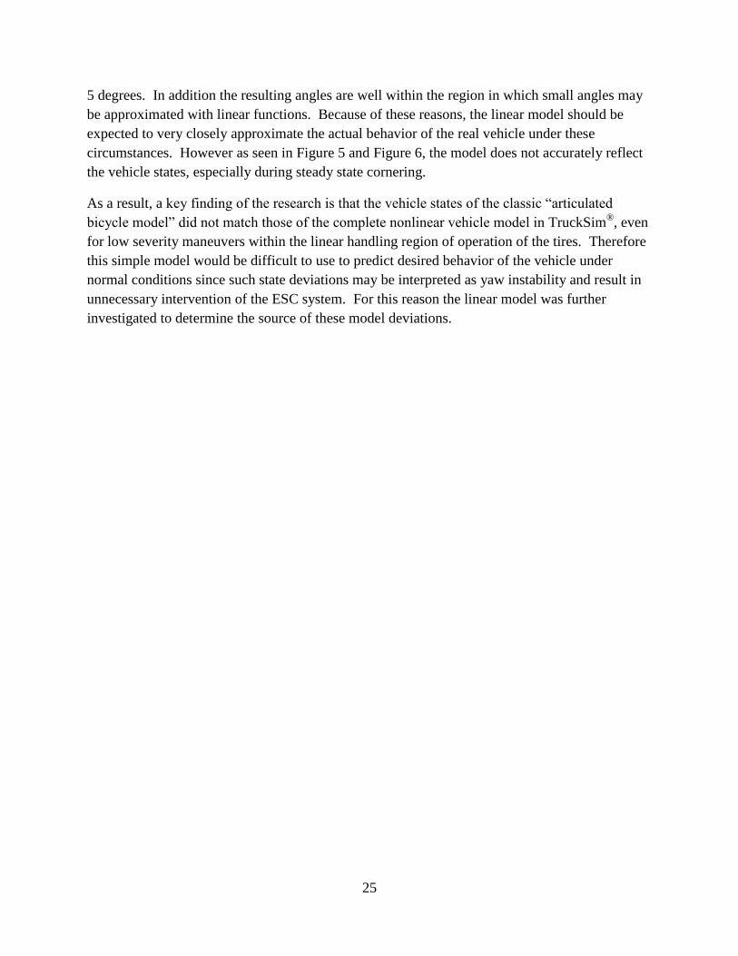
A key finding of the research is that the vehicle states of the classic “articulated bicycle model”
did not match those of the complete nonlinear vehicle model in TruckSim®, even for low severity
maneuvers within the linear handling region of operation of the tires. As a result, this simple
model would be difficult to use to predict desired behavior of the vehicle under normal
conditions, since such state deviations may be interpreted as yaw instability and result in
unnecessary intervention of the ESC system.
A thorough investigation into the differences between the linear model and TruckSim® model
resulted in the identification of three main vehicle properties that were the root cause of the
deviations:
1. Axle roll steer
2. Tire lateral force compliance steer
3. Tire aligning moment compliance steer (primarily on front axle)

6
Strategies were devised to incorporate each of these individual effects into the linear articulated
bicycle model. The resulting model was found to have very good agreement with the complete
nonlinear TruckSim® model when exercised with maneuvers in the linear regime.
A yaw stability control system was devised in which the yaw rate was used as a state feedback
variable. Co-simulation tests were executed using a lane change maneuver on a low friction
surface implemented in TruckSim®. Without ESC activation, the tractor and trailer develop
significant amounts of sideslip and the combination vehicle experiences large yaw oscillations
when exiting the maneuver. With the designed ESC system co-simulated with the TruckSim®
model executing the same maneuver, the vehicle sideslip and trailer oscillations were
significantly reduced throughout the maneuver.
In addition, roll stability control was realized with a second algorithm executing in parallel to the
yaw stability control algorithm. This control strategy used simple thresholds for the tractor and
trailer lateral acceleration based upon static rollover threshold values for typical tractors and
loaded trailers found in the literature. When tractor lateral acceleration or estimated trailer
lateral acceleration exceeded these thresholds, brakes were applied to all vehicle wheels to
reduce vehicle speed and thus lateral acceleration. Simulations of step steer maneuvers with the
co-simulation system proved the strategy to be an effective means of mitigating the threat of
vehicle rollover.
Track Testing Preliminary Results
As described previously, track testing of a tractor and tanker semi-trailer was conducted to
provide data to use for the validation of the ESC co-simulation project. This testing was
conducted in conjunction with the HTRC Phase B project. Members of both project teams
collaborated on all test planning phases, test execution, and post-test analysis of the data. While
some test instrumentation and maneuvers were designed specifically for the ESC Co-Simulation
project, the majority of instrumentation and test maneuvers were designed to yield data of use for
both projects.
The vehicle tested was a Volvo VT830 tractor with an LBT tanker trailer. Four maneuvers were
used for testing: slowly-increasing ramp steer, step steer, dry double lane change, and wet double
lane change. The Volvo tractor was equipped with a Bendix full ESC system and the trailer was
equipped with an independent Bendix roll stability control system. Tests for the various
maneuvers were executed with various combinations of tractor and trailer stability control
systems enabled/disabled. In addition, different vehicle configurations were tested. All
maneuvers were repeated for vehicle configurations with standard dual tires with the tanker fully
loaded in both a “high” center of gravity (CG) configuration and a “low” CG configuration. In
addition, some maneuvers were also repeated with a configuration of new generation single
wide-based tires (NGSWBT) and the “high” CG configuration. A steering robot was used to
conduct all tests. For the ESC Co-Simulation project, the objective was to produce data that

7
could be used to validate the ESC co-simulation system. A thorough validation of the ESC co-
simulation system using the track test data is being deferred to the proposed subsequent Phase B
of the project. After completion of the testing, an initial analysis of the track test data with
tractor ESC systems enabled and disabled (but with trailer stability control disabled) was
conducted. The purpose of this investigation was a qualitative analysis to determine whether the
logic applied to the baseline ESC algorithm developed based on available literature matched the
behavior of the commercial ESC system. The following is a summary of the basic analysis of
tractor ESC performance for the four defined test maneuvers.
A slowly increasing ramp steer test was used to simulate quasi-steady state conditions. For this
test the steering wheel angle was increased at a rate of 10 deg/sec while the driver attempted to
maintain a constant speed of 30 mph (unless the ESC system intervened with throttle control).
This test was used primarily by the HTRC project team to determine basic vehicle properties
such as understeer characteristics. However, the maneuver can be used to evaluate the roll
stability control (RSC) portion of the tractor ESC system as vehicle lateral acceleration increases
linearly with steer input. Tractor ESC intervention was found to occur consistently at
approximately 0.3 g of lateral acceleration. This value is consistent with a static rollover
threshold for a fully loaded trailer as described in available literature. In the low CG case the
RSC application may be at slightly higher lateral acceleration, but this is difficult to say
conclusively. In all ramp steer maneuvers the ESC system intervened by disabling torque
demand of the engine and by applying brakes to the trailer to reduce vehicle speed. Bendix
literature on the system indicates that it will brake all tractor and trailer drive wheels under large
lateral acceleration conditions. The reason for this discrepancy under these conditions is unclear.
A step steer test was conducted using a quick ramp of steering wheel angle to 170 degrees in 1
second at a speed of 33 mph. The test was conducted “dropped throttle” in the sense that the
tractor was put in neutral and allowed to coast while the steering robot and data acquisition
triggered when the target speed was reached. For the high CG configuration step steer with
tractor ESC on and trailer ESC off, the lateral acceleration builds quickly as the steering wheel
ramps. The tractor ESC system did not intervene in the step steer test until the tractor unit
reached approximately 0.4 g of lateral acceleration. This number is considerably higher than the
threshold in the steady state ramp steer test. This is likely a result of the fact that the tractor has a
higher static rollover threshold than that of the trailer due to a lower CG height, and the fact that
the trailer lateral acceleration lags that of the tractor. The exact trigger points for ESC system
intervention cannot be determined conclusively without conducting a prohibitively large number
of tests under different input conditions. When the ESC system intervened in the step steer tests,
all axles of the tractor and trailer were braked as described in the Bendix system literature. Bias
between drive axle left and right wheels and bias between the tractor steer and drive axles was
observed in the system activation at times during the maneuver. The strategy of the system for
introducing bias in the braking activation is unknown.

8
Clemson took the lead role in designing an open-loop steering profile for the steering robot that
would approximate the path of the vehicle during an emergency double-lane change maneuver.
The TruckSim® vehicle model was used with an updated preliminary model of the tanker to
design the maneuver. First a simple driver steering model was used in TruckSim®
to simulate a
driver attempting to follow a profile that effected a double lane change maneuver. The resulting
driver steering input profile was analyzed and a piecewise linear profile suitable for the steering
robot was designed to approximate the steering profile input by the driver model. The
amplitudes and times of points in the profile were varied and simulated again in TruckSim®
to
make sure that the designed open-loop profile resulted in a full double lane change with the
vehicle following approximately the same track at the end of the maneuver as in the beginning of
the maneuver. Subsequent track testing of the actual vehicle using the designed steering robot
profile resulted in a maneuver that closely approximated a double lane change maneuver, but
with far more repeatable results than can be realized by a human driver. For many of the tests
conducted, the amplitude of the steering profile was increased in order to increase steering
severity and induce wheel lift at the relatively low speeds that could be realized on the test track.
Open-loop double lane change maneuvers were conducted on the dry asphalt surface at speeds
found to induce wheel lift for a particular vehicle configuration. In both the high and low CG
configurations, two stability control events were observed when tractor ESC was enabled: one
during the initial lane change to the left and another during the return lane change to the right. In
both cases, ESC brake intervention was similar to that observed for the step steer tests.
However, the second ESC intervention had much lower brake pressures, likely due to the fact
that the vehicle speed was greatly reduced by the initial ESC brake activation.
The ESC system output on the vehicle Controller Area Network (CAN) bus indicates when the
system activates for either a roll stability event or a yaw stability event. A roll stability event
occurs when high lateral acceleration puts the vehicle in danger of imminent rollover. Yaw
instability indicates that the vehicle is not following the intended heading of the driver resulting
in either an understeer or oversteer condition. Due to the high coefficient of friction on the dry
asphalt and the high center or gravity of the combination vehicle, testing on the dry test surface
did not result in any yaw stability interventions by the ESC system. For this reason, tests were
also conducted on a wet Jennite pad available at the Transportation Research Center (TRC) track
test facility. This surface has a far lower coefficient of friction than that of the dry surface and
could be used to induce some yaw instability. However, the surface did not have a peak
coefficient of friction sufficiently low to activate yaw stability events during a maneuver without
activating roll stability events.
In addition, ESC activation during maneuvers conducted on the wet pad were not as repeatable
as the maneuvers conducted on the dry asphalt. However, in some test maneuvers, data clearly
indicates that the ESC system sensed yaw instability and corrected for both understeer and
oversteer conditions briefly during the maneuver. As expected on the initial understeer condition
in the lane change maneuver conducted on the wet pad, the ESC system braked the inside drive

9
wheel to produce an additional moment to help the vehicle steer into the turn as desired. When
the vehicle began the maneuver to return the vehicle to the original lane of travel, sufficient
lateral force was generated to induce a roll stability control event and all wheels were braked as
in the cases on dry pavement. However, immediately following the roll stability event a second
yaw instability event occurred in which the vehicle was oversteering, possibly induced by the
roll stability braking. In this case the system braked the front outside wheel to produce a
restoring moment to straighten the vehicle and correct the oversteer condition. Note that Bendix
literature refers to a tractor oversteer event as a jackknife condition and indicates that in this
situation the system applies brakes to both the outside steer wheel and trailer wheels to straighten
the vehicle. The reason that the trailer brakes were not activated by the system during the
oversteer event is unclear.
In general the testing results indicated that the stability control system intervened qualitatively as
expected based on ESC control strategies described in the available literature. However, a
number of open questions remain regarding the specific strategy used by the Bendix commercial
tractor ESC system. It is likely the case that the Bendix system has a number of “corrections”
implemented in their algorithms to handle special conditions encountered when testing on actual
vehicles. Exhaustive track testing would need to be employed in order to fully characterize the
system. Such testing is obviously prohibitively expensive. As a result, the ESC algorithm
developed for co-simulation may be validated in a future project phase for the specific
maneuvers tested, however the simulated ESC algorithm may not accurately reproduce the
behavior of the commercial system under all dynamic conditions that may be realized in
simulation conditions.
Future Program Efforts
The proposed Phase B of the project entails the investigation of advanced heavy tractor trailer
ESC system concepts. The baseline ESC algorithm developed in the Phase A co-simulation
project will be validated against track test data obtained as part of that project. This ESC
algorithm will serve as the baseline for comparison for any potential benefits of the advanced
ESC system developed. The addition of new on-board system sensors will be investigated, while
keeping an emphasis on cost effectiveness. In addition, a communication link between the
vehicle tractor and trailer will be considered to enable the exchange of vehicle configuration
information, sensor data, etc. Advanced ESC algorithms that will take advantage of the
additional sensor and communication data will be developed to provide additional system
robustness and performance. A design proposal for an advanced prototype ESC system for the
HTRC “SafeTruck” vehicle that takes advantage of these improvements will be developed.
The research is to be conducted by Clemson University with assistance from Michelin Americas
Research Company and Bendix Commercial Vehicle Systems. Michelin and Bendix will
provide oversight and guidance on the development of advanced stability control system
concepts. Michelin will also continue to provide support in the form of truck modeling as part of

10
both the HTRC and ESC projects. In addition, National Instruments will provide support in the
form of a LabVIEW™
software license to be used for ESC algorithm modeling and simulation.
The Phase B project is expected to last for one year, with the possibility of follow-on research in
subsequent years. This second year of research will primarily consist of research on novel
advanced ESC system concepts including sensors, vehicle communication, and algorithms.

11
Chapter 1 – General Overview
Background
A study by the Insurance Institute for Highway Safety on all types of road vehicles has found
that Electronic Stability Control (ESC) systems “could prevent nearly one-third of all fatal
crashes and reduce the risk of rolling over by as much as 80 percent.” In light of these benefits,
NHTSA has issued Federal Motor Vehicle Safety Standard 126, which mandates that all new
light vehicles include ESC systems as standard equipment by September 2011. While the
inclusion of ESC on heavy trucks is not yet mandated, increasingly the cost benefits of such
systems are being emphasized by suppliers and OEMs and it is believed that legislation
mandating ESC systems on heavy trucks is on the horizon.
It is well known that the interaction of vehicle dynamics and tire dynamics play a significant role
in the overall vehicle handling and performance. This is true for heavy trucks, and significant
effort is made to understand these interactions when designing new tires for a particular truck.
One tool commonly used is numerical simulation on the computer. Mathematical models of the
vehicle and tires of adequate fidelity can produce simulation results that are representative of the
performance of the real vehicle. Increasingly passenger vehicles as well as heavy trucks are
being outfitted with ESC systems that enhance vehicle stability at the limits of vehicle
performance. While the vehicle and tire dynamics involved are well understood, the ESC
algorithms are generally proprietary to the system suppliers and therefore their effect on the
vehicle performance at the limits of handling cannot be readily simulated. A Hardware-In-the-
Loop (HIL) simulation system that incorporates the ESC system electronic control unit hardware
into the simulation will provide a means of using computer simulation to investigate these effects
without having knowledge of the underlying control algorithms themselves.
State-of-the-art vehicle stability control systems operate by comparing vehicle dynamic behavior
to a pre-determined non-linear time-invariant dynamic model of the vehicle. This generally
results in acceptable behavior for passenger vehicles in which the load variations are minor due
to passengers, luggage, etc. Key parameters such as sprung mass, moments of inertia and height
of center of gravity only vary by a small percentage, making the model used in the ESC system
adequate for minor variations. However, in a heavy truck there are substantial load variations
due to the presence/absence of a trailer, trailer cargo mass, cargo distribution, height of cargo,
etc. that could have a significant impact on the model. It is not clear that a stability control
system tuned to one particular heavy truck configuration provides adequate performance over all
vehicle configurations. In addition, it may be the case that the configuration of the ESC model
provides the most conservative control action, and thus over-corrects for other load
configurations. The HIL simulation system and models described above may be used to
investigate the effect of load variations described above on a truck equipped with a commercial
ESC system. In addition the system may serve as a simulation platform to investigate the
effectiveness of adaptive ESC algorithms designed to overcome these limitations.

12
Project Team
This research was conducted by organizational participants from academia and private industry.
Specifically, the partners in the project included:
Michelin Americas Research Company (MARC)
Clemson University (CU)
National Instruments Corp.(NI)
Other Heavy Truck Rollover Characterization (HTRC) project partners:
o Oak Ridge National Laboratory
o Battelle Memorial Institute
o Western Michigan University
MARC Roles and Responsibilities
The primary roles and responsibilities of MARC in this project involved them as the primary
industry technical lead. MARC’s roles included simulation modeling, on-track testing, and data
analysis. MARC’s close technical relationship with Clemson University has facilitated a strong
understanding of the role of tires in vehicle dynamics and stability.
Clemson University Roles and Responsibilities
Professors Thomas R. Kurfess and E. Harry Law of the Department of Mechanical Engineering
led Clemson’s effort on the research project. Doctoral candidate John Limroth provided the
student labor on the project. CU had a leading role in all project tasks.
National Instruments Roles and Responsibilities
NI provided direct financial support as well as the core hardware and software components of the
real-time HIL system. This included the PXI system for simulation of the vehicle and tire
models, and the LabVIEW™
, LabVIEW™
Real-Time, LabVIEW™
Simulation and LabVIEW™
FPGA software necessary for simulation development. NI also provided all I/O boards including
data acquisition, Controller Area Network bus boards, and associated signal conditioning and
cables.
Project Description and Objectives
The overall objectives of this research were to:
Determine performance of the truck ESC system and validate against measured test track
data.
Understand the fundamental operation of the ESC system with respect to vehicle
dynamics
Determine the robustness of the ESC system with respect to vehicle configurations and
various vehicle parameters

13
Study potential improvements to vehicle stability and/or dynamic performance with the
ESC system active due to changes in vehicle parameters
Investigate further improvements in stability control and system identification algorithm
performance through closed-loop simulation with vehicle models
This project entailed the following activities:
1. A review of literature relevant to the operation of heavy truck ESC systems
2. Investigation of a Hardware-In-the-Loop (HIL) simulation system for truck/ESC system
co-simulation
3. Investigation of an offline software co-simulation system
4. Track testing of a tractor/semi-trailer coordinated with Heavy Truck Rollover
Characterization project
5. Initial investigation of the track testing results for ESC co-simulation system validation
Literature Review
A review of relevant literature was conducted to understand the state-of-the-art of heavy truck
electronic stability control algorithms. A review of passenger car ESC algorithms was conducted
to understand the fundamental operation of these systems since adoption of ESC in the passenger
car market preceded that of the heavy truck market. In addition, a review of the relevant
literature on ESC and roll control systems for articulated heavy truck was conducted.
In addition to ESC algorithms, the literature review included models of articulated trucks used
for both control algorithms and simulation systems. Since a dynamic model of the articulated
truck lateral handling was found to serve as the basis for determining desired vehicle behavior in
ESC systems, a survey of low-order models suitable for processing on an ESC embedded
controller was conducted. In addition, high-fidelity commercial tools capable of simulating
tractor/semi-trailer systems such as TruckSim® and SIMPACK
® were reviewed.
The literature review was provided previously in the project interim report, and is provided again
in Appendix A– Literature Review for the sake of completeness.

14

15
Chapter 2 – ESC HIL Simulation Investigation
Investigation of the available information on input/output signals to the ECU resulted in the
determination that insufficient details of the ECU operation were available for integration into an
HIL system. This included unpublished requirements of the sensors/actuators for diagnostics
purposes and proprietary communication buses used in the system. The initial project proposal
included engaging the ESC ECU supplier, Bendix Commercial Vehicle Systems, as a partner in
the project. However, as Bendix involvement occurred very late in the project timeline, the
project focus was shifted away from an HIL simulation system and instead focused on a software
co-simulation system.
HIL Project Tasks
Simulation Model Development
An initial TruckSim® model of the Volvo Test truck was developed by Michelin and provided to
Clemson. Clemson acquired the TruckSim® license and a real-time license that would enable
HIL simulation within LabVIEW™
Real-Time on the National Instruments hardware. The model
provided by Michelin was verified on the host personal computer and basic handling maneuvers
were simulated.
The first TruckSim® model of the Volvo Truck provided by Michelin has been tested in offline
simulation on the host computer. While the model developed by Michelin incorporates the
TruckSim® flexible frame option, this option is not included in the license obtained for this
project and therefore the model feature has been disabled. This feature is not critical for the
handling maneuvers necessary for ESC system testing in either offline or HIL simulation.
In addition to the TruckSim® model, a baseline 4 Degree of Freedom (DOF) simulation model
was developed for the project. This model, based on first principles, provides an analytical
model to which the TruckSim® model may be compared. The analytical model should provide
insight into the ESC system operation.
ESC Control Algorithm Development
A basic state feedback controller for ESC on an articulated heavy truck has been developed.
This controller is of a standard form as found in the literature described in Appendix A. The
controller was initially tested against an arbitrary truck model before the Volvo TruckSim®
model parameters were available. This standard controller is now being adapted to the specific
Volvo test truck used in this project.
Integration of Michelin Tire Models
Models of the Michelin XZA3 and XDA tires were provided by Michelin with the Volvo VT830
TruckSim® model. An agreement was established between Clemson and Michelin for the

16
purpose of sharing this confidential tire information. These tire models will be used for initial
model development and simulation.
ESC Hardware Acquisition
While quotes have been obtained for the ECU and peripheral ESC system hardware, this
equipment has not yet been acquired. The reason for this is that the specific equipment required
depends upon whether the actual system sensors and actuators are required. For example, the
actuator valves may need to be present for the ECU to pass initial diagnostic tests on startup, and
may also be necessary to ensure that the valve electrical characteristics detected by the ECU are
within expected ranges. In addition, if Bendix is not willing to provide information regarding the
local CAN communication bus between ECU, yaw angle sensors, and steer angle sensors, then
these hardware components may need to be integrated into the system. The specific hardware
will be acquired after the status of participation by Bendix has been established.
HIL Hardware Specification
The following hardware required for the HIL test system has been specified for the project:
1. Middle Atlantic 21 Space Rolling Rack
The rack will house all HIL hardware and includes two sliding shelves and a Tripp-Lite
power strip.
2. B&K Precision 13.8 VDC 4A Power Supply
The 4 Amp power supply can be used to power auxiliary devices such as the yaw rate and
steer angle sensor packs. A larger power supply capable of supplying 30 Amps for valve
actuation is available in-house at Clemson and will be used for the project.
In addition, the National Instruments hardware required for the real-time simulator has been
specified. This includes a PXI controller and chassis that will serve as the real-time computer for
running TruckSim® simulation models. In addition, all I/O devices and signal conditioning
hardware has been specified. The LabVIEW™
software and associated modules required are
also specified. The complete set of NI hardware is indicated in Table 1.

17
Table 1. Specified National Instruments Hardware and Software.
Controller and Options
779886-33 NI PXI-8106 RT Controller 1
779302-1024 1.5 GB RAM 1
779660-01 USB English Keyboard and Optical Mouse 1
Modules and Options
780340-01 NI PXI-7852R RIO Module 1191667-01 SHC68-68-RDIO Cable (1m) 2
189588-01 SHC68-68-RMIO Cable (1m) 1776844-01 SCB-68 Connector Block 1
Chassis and Options
778636-02 NI PXI-1042Q Chassis 1
960597-08 PXI 8-Slot Factory Installation Service 1
763000-01 United States 120VAC 1
778643-01 PXI Rack Mount Kit (Front) 1
778643-02 PXI Rack Mount Kit (Rear) 1
CompactRIO
779008-01 NI 9151 R Series Expansion Chassis 2
779429-01 NI 9853 CAN Module 1
192017-02 NI CAN High-Speed Cable, 2m 1779372-01 NI 9201 AI Module 1
779104-01 NI 9934 25pin D-Sub connector kit 2
779012-01 NI 9263 AO Module 1
779017-01 NI 9932 Backshell with 10-pos connector block 1
779351-01 NI 9401 DIO Module 1
779006-01 NI 9481 Relay Module 1
779017-01 NI 9932 Backshell with 10-pos connector block 1
779097-01 NI 9904 Panel Mounting Kit 1
Software
778694W-09 LabVIEW FPGA Module + 1 Yr SSP 1
777844W-09 NI LabVIEW Real-Time Module + 1 yr SSP 1
776678-09 NI LabVIEW PDS + SSP 1
777136-01 LabVIEW Advanced Signal Processing Toolkit 1
778941-03 LabVIEW System Identification Toolkit 1
780050-09 LabVIEW Control Design and Simulation Module 1
779953-09 LabVIEW Statechart Module 1
HIL Hardware Acquisition
All hardware specified in the HIL Hardware Specification section above has been acquired.
Figure 4 shows a picture of the rack and associated hardware for the HIL test system. The power
strip and National Instruments Real-Time PXI controller and chassis are located at the top of the
rack. The first sliding shelf contains the B&K power supply (right) and Bendix ESC ECU and
Yaw Angle Sensor pack (left). The ECU and sensor pack were removed temporarily from the
Volvo test truck for the purposes of system development. The actual components to be used in
the HIL system have not yet been acquired.

18
Figure 4. Photograph. HIL Rack and Equipment.
HIL ECU Sensor and Actuator Integration
John Limroth met with several HIL simulation experts to discuss I/O aspects of the HIL system
and the need for information from the ECU supplier. The HIL experts indicated a strong need
for information from the supplier in the areas of diagnostic information, system initialization and
I/O information.
Further investigation into the ECU requirements and meetings with Hardware-In-the-Loop
experts have led to the determination that cooperation from the ECU manufacturer Bendix is
critical. John met with several experts during National Instruments’ NIWeek conference to
discuss the project:
Discussions with NI experts on CAN/J1939:
o Sensor CAN-bus reverse-engineering possible, but will be difficult
o J1939 bus standards are defined, but which signals are used (and when) by the ECU
needs to be known
Discussions with NI experienced HIL partners:
o ECU switches power to actuator valves, therefore a high output (300W) power supply
and actual valves are needed in the HIL system

19
o Valves are actuated via voltage, but current on the line is monitored by the ECU to
determine valve position feedback. These electrical signals are difficult to simulate
without actual valves.
o ECU diagnostics are critical for development and debugging. A diagnostic interface
tool is needed, and the sensor/actuator impedances must be matched correctly.
Information Required of ECU Supplier
Michelin organized a meeting with Bendix to discuss participation in the project. While the
initial indication from Bendix was positive, at that meeting no specific plan was established for
sharing information regarding the ECU for this project. The partnering discussions are taking far
longer than was anticipated when the original schedule was developed. If Bendix is involved
and supportive, they could provide much needed aid in the development of the I/O for the HIL
system. Further investigation into the HIL system and meetings with external experts has led to
the conclusion that cooperation from Bendix is critical to the successful implementation of the
HIL system. The critical nature of the information has been relayed to Michelin who is
maintaining the relationship with Bendix. Michelin will continue to pursue Bendix and request
the necessary information.
The following is a list of specific information needed from Bendix for the development of the
HIL system:
Details of CAN bus communication with Yaw Angle (YAS) and Steer Angle (SAS) sensor
packs
Details of powertrain J1939 bus communication (which signals, and when?)
Sensor/actuator inductance/resistance matching for diagnostics (e.g. valve “chuff” test)
Specific hardware needs for HIL system
o Valves absolutely required for HIL?
o Additional sensors or hardware?
Need to simulate Power Line Carrier (PLC) signal for trailer ECU?
Alternative Project Plan: Truck/ESC Co-Simulation
An offline software simulation will be developed in which the TruckSim® model will be co-
simulated with an ESC control algorithm implemented in LabVIEW™
. This will provide an
alternative configuration that will allow closed loop testing of the vehicle model, tire models, and
ESC algorithm, although without the actual ESC algorithm of the commercial ECU that would
be present in the HIL test system. The system will also provide an interface to the ESC system
that will be used in the real-time implementation of the HIL system should ECU information be
forthcoming from Bendix.

20

21
Chapter 3 – ESC Software Co-Simulation
Software Co-Simulation System
Due to the lack of available information required for the implementation of a HIL simulation
system during Phase A of the project, a pure software co-simulation strategy was pursued. In
this case the vehicle model is not run in real-time on dedicated hardware, but instead is simulated
on a standard desktop PC. However, a second simulation environment is used to model the
behavior of the ESC control algorithm. For this project, LabVIEW™
was used to implement an
ESC algorithm that is representative of those found in the available literature. LabVIEW™
and
TruckSim® are used together to “co-simulate” the complete vehicle with an ESC system.
Information must be exchanged at each simulation timestep between the two tools to ensure that
the complete system is accurately simulated. A schematic view of the software co-simulation
system is shown in Figure 2.
Yaw Stability Control
Heavy truck ESC systems found in the literature typically implement a state feedback control
scheme with a linear vehicle model used to determine “desired” states of the vehicle. A
schematic view of the control strategy used in the co-simulation system is provided in Figure 3.
A critical component of the algorithm is the use of a linear dynamic model to determine the
desired vehicle states based on vehicle speed and steering input. The model is the “articulated
bicycle” handling model commonly found in the literature with the following states: tractor
lateral velocity, tractor yaw rate, trailer relative articulation angle and articulation rate.
The yaw stability portion of the controller is shown in the figure. Here yaw rate and lateral
acceleration are used as model outputs and are compared to the measured values from
TruckSim® model outputs corresponding to actual sensors used on the real vehicle. A threshold
is used to prevent intervention under normal driving conditions and feedback gains are applied to
the state deviations. The resulting control output includes logic to apply differential braking
pressures to appropriate axles of the vehicle to correct the instability. These pressures serve as
setpoints to individual wheel ABS controllers also implemented in LabVIEW™
, but not depicted
in the simple schematic figure shown.
Linear Model Development
As seen in Figure 3, a simple dynamic model of the vehicle yaw behavior is a critical component
of the yaw stability control algorithm. For this reason great care was taken to ensure that the
linear model used in the algorithm accurately reflects the true behavior of the vehicle. The linear
model used is the classic 4th
order “articulated bicycle” model found in Genta [1]. Longitudinal
dynamics of the vehicle are not included in the model as the vehicle speed is assumed to be
approximately constant. The input to the model is the steering wheel angle, which is sensed in

22
the actual vehicle ESC system. The model used for this research is based on the Genta model
and includes these forces on the vehicle lateral motion:
1. Tire lateral force due to cornering stiffness
2. Tire aligning moment due to aligning stiffness
3. Tire longitudinal force
4. Longitudinal aerodynamic drag
5. Aerodynamic yaw moment.
The states used for this model are:
1. Lateral velocity, vy
2. Yaw rate, dψ/dt
3. Trailer articulation angle, θ
4. Trailer articulation angular rate, dθ/dt.
The model outputs include all vehicle states, as well as the tractor and semi-trailer lateral
accelerations. These lateral accelerations were added to the model since these are simple linear
combinations of the vehicle states and their time derivatives as shown in Equation 1. It should
be noted that only the vehicle yaw rate and lateral accelerations are actually sensed by the ESC
system as no sensors are provisioned for measuring lateral velocity or trailer articulation.
,
y y x
y S y x S
A v v
A v v c a
Equation 1. Tractor and Semi-Trailer Lateral Accelerations.
The linear model was developed using the geometrical and other properties of the Volvo VT830
tractor and Utility flatbed trailer used for testing in the Heavy Truck Rollover Characterization
study. The model was implemented in LabVIEW™
and used in a co-simulation manner in order
to directly compare the outputs of the linear model with those of the high-fidelity TruckSim®
model. The steering input used in the TruckSim®
simulations was output to LabVIEW™
and the
linear model run in parallel to the TruckSim® model. The signals corresponding to the model
outputs were also output from TruckSim® and plotted against the outputs of the linear model.
An example for a step steer type maneuver is shown below in Figure 5 and Figure 6.

23
Figure 5. Graphs. Step Steer Model Response, 100 kph (a).

24
Figure 6. Graphs. Step Steer Model Response, 100 kph (b).
Note that the steering wheel input for the maneuver shown is about 20 degrees, which results in a
road-wheel angle of ~1 deg. This is well within the linear range of the slip angles at the tires –
the tire models used in TruckSim® exhibit linear lateral force response to slip angles up to about
25
5 degrees. In addition the resulting angles are well within the region in which small angles may
be approximated with linear functions. Because of these reasons, the linear model should be
expected to very closely approximate the actual behavior of the real vehicle under these
circumstances. However as seen in Figure 5 and Figure 6, the model does not accurately reflect
the vehicle states, especially during steady state cornering.
As a result, a key finding of the research is that the vehicle states of the classic “articulated
bicycle model” did not match those of the complete nonlinear vehicle model in TruckSim®, even
for low severity maneuvers within the linear handling region of operation of the tires. Therefore
this simple model would be difficult to use to predict desired behavior of the vehicle under
normal conditions since such state deviations may be interpreted as yaw instability and result in
unnecessary intervention of the ESC system. For this reason the linear model was further
investigated to determine the source of these model deviations.
26
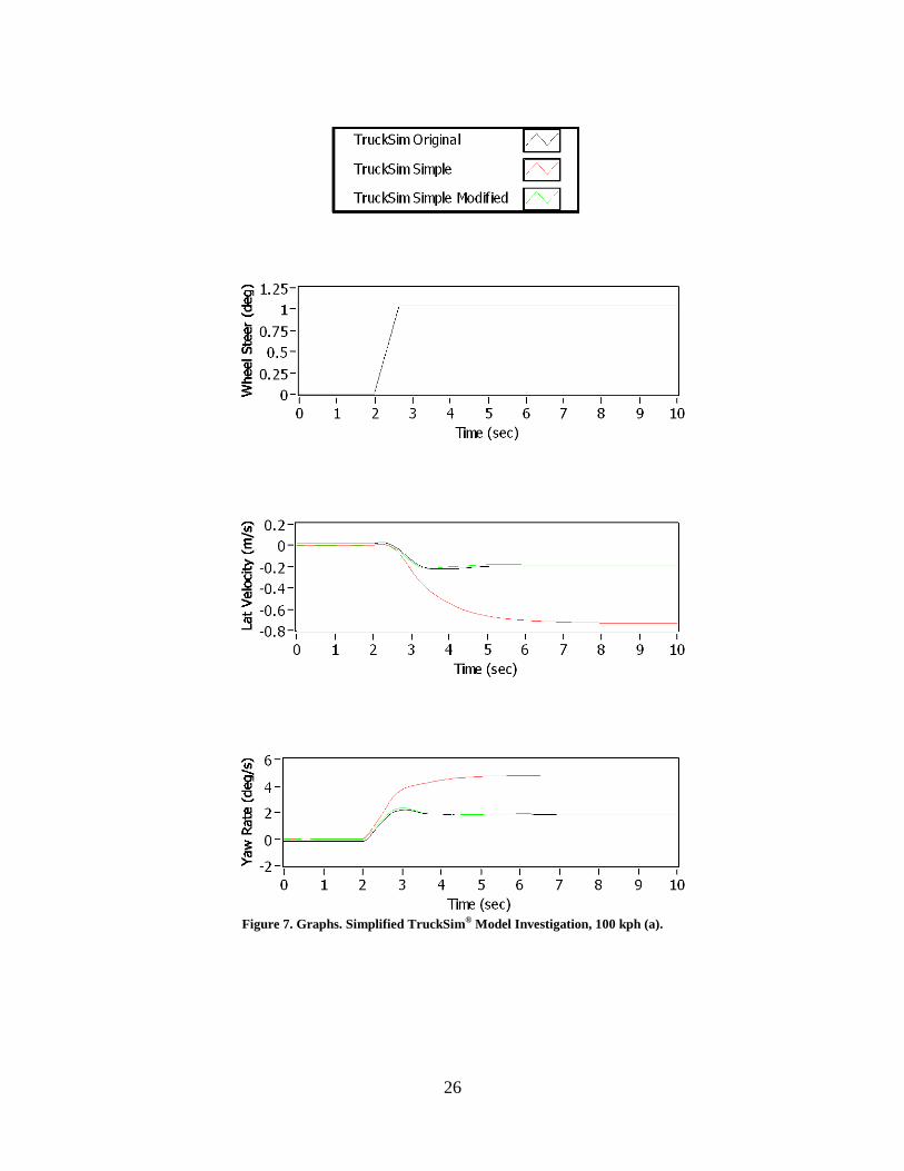
Figure 7. Graphs. Simplified TruckSim® Model Investigation, 100 kph (a).

27
Figure 8. Graphs. Simplified TruckSim® Model Investigation, 100 kph (b).
28
A modified TruckSim® model was created with greatly simplified suspension models for the
tractor and trailer. While the original suspension models are fully nonlinear and incorporate all
measured effects from kinematics and compliance testing, the simplified suspension models only
incorporate linear spring force and damper force coefficients. A comparison of these models can
be seen in the black and red traces of the plots shown in Figure 7 and Figure 8. The simplified
TruckSim® model was found to be in very good agreement with the linear model computed using
LabVIEW™
and shown in Figure 5 and Figure 6.
Individual suspension effects were incorporated into the simplified suspension models in
TruckSim® in an effort to identify the key characteristics responsible for the deviations from the
complete suspension model. After much trial and error, a modified linear suspension model with
some of the measured kinematic and compliance effects incorporated was found to be in very
good agreement with the original fully nonlinear model. This can be seen in the green traces of
Figure 7 and Figure 8. The specific suspension properties found to be responsible for the
majority of the model deviations are:
1. Axle roll steer
2. Tire lateral force compliance steer
3. Tire aligning moment compliance steer (primarily on front axle).
The “Simple Modified” model results shown in Figure 7 and Figure 8 are from a model with the
linear spring and force components as well as linear coefficients corresponding to these three
identified properties. In order to realize a linear model for ESC algorithm use, strategies were
devised to incorporate these three effects were into the standard linear vehicle model.
Axle Roll Steer
Axle roll steer is a kinematic effect by which an axle causes a steer angle of the wheels as the
vehicle sprung mass rolls in response to lateral forces on the vehicle. This effect is common in
trailing arm suspensions such as those on the tractor drive axles and trailer axles. A simple linear
coefficient can be used to represent axle wheel steer as a function of relative roll angle between
an axle and the vehicle sprung mass as seen in Equation 2.
, ,rollsteer i i suspension i
Equation 2. Axle Linear Roll Steer Model.
In order to incorporate this effect into the model, a quasi-steady state model of the roll steer
effect was employed since a roll degree of freedom is not included in the present vehicle
handling model. The steady state model assumes that the vehicle roll angle is that which
produces equilibrium between the roll moment generated from lateral acceleration and the roll
moment generated from the roll stiffness of the suspension. The specific implementation in the
model is shown in Equation 3. The lateral acceleration is used to determine the vehicle roll angle
at equilibrium due to the equivalent suspension roll stiffness kφ. This equivalent roll stiffness is

29
due to suspension and axle roll stiffness combined in series at each axle, with all axles assumed
to be acting in parallel on the vehicle sprung mass. The axle roll relative to the vehicle roll angle
can then be found from the relative suspension roll stiffness and axle roll stiffness due to the tires
for each axle. The roll steer effect is then implemented using Equation 2. As a result the roll
steer effect at each axle is simply a linear function of the yaw rate and is easily incorporated into
the linear vehicle model.
,
,
, ,
y y x x
y
axle i
susp i
axle i susp i
A v v v
k A
k
k k
Equation 3. Quasi-Steady State Roll Model.
Lateral Force and Aligning Moment Compliance Steer
Lateral force compliance steer is an effect in which the lateral force generated at the wheels
induces a steer effect due to compliance of the suspension mechanism. Again, such an effect is
present especially on trailing arm suspensions. Aligning moment compliance steer is a similar
effect where the aligning moment generated at the wheels due to pneumatic and mechanical trail
produces additional steer effect due to suspension compliance. This effect is especially present
on the tractor steer axle due to compliance effects in the steering mechanism.
The lateral force compliance steer effect can be approximated for a small region of operation
using a linear coefficient as seen in Equation 4.
y ycF cF yk F
Equation 4. Linear Lateral Force Compliance Steer Model.
The net result is a slight reduction in the lateral force generated for a given slip angle of the
wheel since the slip angle itself is slightly reduced due to the compliance steer effect. Assuming
a nominal wheel slip angle α0 without compliance steer, the lateral force generated at the wheel
due to axle linear cornering stiffness Cα is shown in Equation 5. Thus the compliance steer
effect can be modeled by changing the axle cornering stiffness as shown in Equation 6. Note
that due to sign conventions the lateral force compliance steer coefficient for tractor and trailer
axles all have negative values. Thus the net effect is a slight reduction in cornering stiffness.

30
0
0
01
y
y
y
y
cF
cF y
cF
F C
C
C k F
C
k C
Equation 5. Lateral Force Model.
,*
,
, ,1y
i
i
cF i i
CC
k C
Equation 6. Effective Cornering Stiffness Due to Lateral Force Compliance.
The lateral force compliance steer also affects the tire aligning moment in a similar manner.
This can be represented with an effective aligning stiffness as shown in Equation 7.
,*
,
, ,1
z
z
y
M i
M i
cF i i
CC
k C
Equation 7. Effective Aligning Stiffness Due to Lateral Force Compliance.
Note that the aligning moment compliance steer effect can be modeled in a manner completely
analogous to the lateral force compliance steer effect. The net result is an effective change in
cornering stiffness and aligning stiffness at each axle as shown in Equation 8 and Equation 9 .
Note the tractor and trailer axles have positive values for aligning moment compliance steer
coefficient, and thus the net result is a reduction in both cornering stiffness and aligning stiffness.
*
,**
,
, ,1z z
i
i
cM i M i
CC
k C
Equation 8. Effective Cornering Stiffness Due to Aligning Moment Compliance.
*
,**
,
, ,1
z
z
z z
M i
M i
cM i M i
CC
k C
Equation 9. Effective Aligning Stiffness Due to Lateral Force Compliance.
The result of the described modifications to the linear tractor/semi-trailer model can be seen in
Figure 9 and Figure 10. Each of the linear models represents the addition of each additional
effect of axle roll steer, lateral force compliance steer and aligning moment compliance steer.
The linear model that includes all three effects can be seen to very closely match the original
complete nonlinear TruckSim® model. During transients some deviation can be observed in the
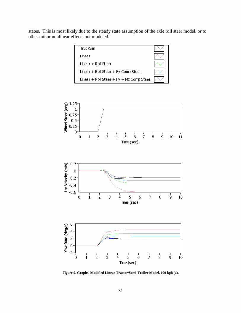
31
states. This is most likely due to the steady state assumption of the axle roll steer model, or to
other minor nonlinear effects not modeled.
Figure 9. Graphs. Modified Linear Tractor/Semi-Trailer Model, 100 kph (a).

32
Figure 10. Graphs. Modified Linear Tractor/Semi-Trailer Model, 100 kph (b).

33
Yaw Stability Control Algorithm
A yaw stability control system was devised in which the yaw rate was used as a state feedback
variable. The structure of the controller used is shown in Figure 3. The linear model described
above was generated for vehicle speeds from 10 to 100 kph in increments of 10 kph. During
execution of the algorithm, the linear model coefficients were linearly interpolated based on the
current vehicle speed in order to yield an accurate model of the vehicle lateral dynamics. The
interpolation was found to yield good accuracy without requiring excessive computation of
model coefficients or excessive memory requirements for additional models at smaller speed
increments.
A threshold of 2 deg/sec for error between measured yaw rate and desired yaw rate (from the
linear model) was selected. This threshold was found to be sufficient to avoid unnecessary ESC
system intervention, yet still provide quick actuation of the system when significant error in yaw
rate was detected. A yaw rate feedback gain of 0.05 brake demand % / (deg/sec) was determined
by hand tuning the model to yield sufficient control. The resulting brake demand % was
distributed to the inside drive wheels in the case of understeer and to the outside steer wheel and
trailer wheels in the case of oversteer. An ABS control system was also modeled in LabVIEW™
to avoid wheel lock when braking during ESC events. The ESC system determines a command
brake pressure for each wheel ABS control system, which then modulates individual brake
pressures to ensure that appropriate wheel slip is maintained. Note that the tractor has four brake
actuation valves: two to control right and left steer wheels, one to modulate both right drive
wheels and one to modulate both left drive wheels. The trailer system has a single valve to
control all four trailer wheels.
Co-simulation tests were executed using a lane change maneuver on a low friction surface (µ =
0.2) at 100 kph implemented in TruckSim®. The results of the yaw stability control system can
be seen in Figure 11 and Figure 12. Without ESC activation, the tractor and trailer develop
significant amounts of sideslip and the combination vehicle experiences large yaw oscillations
when exiting the maneuver. With the designed ESC system co-simulated with the TruckSim®
model executing the same maneuver, the vehicle sideslip and trailer oscillations were
significantly reduced throughout the maneuver. In addition, the driver steering effort is
significantly reduced when the ESC system is activated, as seen in the Road Wheel Angle
(RWA) plot of Figure 11.

34
Figure 11. Graphs. ESC System Co-Simulation on Low Friction Surface, 100 kph (a).

35
Figure 12. Graphs. ESC System Co-Simulation on Low Friction Surface, 100 kph (b).

36
37
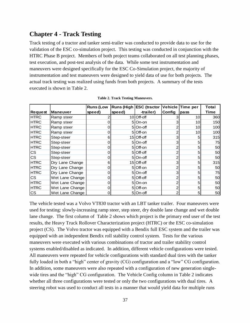
Chapter 4 - Track Testing
Track testing of a tractor and tanker semi-trailer was conducted to provide data to use for the
validation of the ESC co-simulation project. This testing was conducted in conjunction with the
HTRC Phase B project. Members of both project teams collaborated on all test planning phases,
test execution, and post-test analysis of the data. While some test instrumentation and
maneuvers were designed specifically for the ESC Co-Simulation project, the majority of
instrumentation and test maneuvers were designed to yield data of use for both projects. The
actual track testing was realized using funds from both projects. A summary of the tests
executed is shown in Table 2.
Table 2. Track Testing Maneuvers.
Request Maneuver
Runs (Low
speed)
Runs (High
speed)
ESC (tractor
-trailer)
Vehicle
Config
Time per
pass
Total
Time
HTRC Ramp steer 2 10 Off-off 3 10 360
HTRC Ramp steer 0 5 On-on 3 10 150
HTRC Ramp steer 0 5 On-off 2 10 100
HTRC Ramp steer 0 5 Off-on 2 10 100
HTRC Step-steer 6 15 Off-off 3 5 315
HTRC Step-steer 0 5 On-off 3 5 75
HTRC Step-steer 0 5 Off-on 2 5 50
CS Step-steer 0 5 Off-off 2 5 50
CS Step-steer 0 5 On-off 2 5 50
HTRC Dry Lane Change 6 15 Off-off 3 5 315
HTRC Dry Lane Change 0 5 Off-on 2 5 50
HTRC Dry Lane Change 0 5 On-off 3 5 75
CS Wet Lane Change 0 5 Off-off 2 5 50
HTRC Wet Lane Change 0 5 On-on 2 5 50
HTRC Wet Lane Change 0 5 Off-on 2 5 50
CS Wet Lane Change 0 5 On-off 2 5 50
The vehicle tested was a Volvo VT830 tractor with an LBT tanker trailer. Four maneuvers were
used for testing: slowly-increasing ramp steer, step steer, dry double lane change and wet double
lane change. The first column of Table 2 shows which project is the primary end user of the test
results, the Heavy Truck Rollover Characterization project (HTRC) or the ESC co-simulation
project (CS). The Volvo tractor was equipped with a Bendix full ESC system and the trailer was
equipped with an independent Bendix roll stability control system. Tests for the various
maneuvers were executed with various combinations of tractor and trailer stability control
systems enabled/disabled as indicated. In addition, different vehicle configurations were tested.
All maneuvers were repeated for vehicle configurations with standard dual tires with the tanker
fully loaded in both a “high” center of gravity (CG) configuration and a “low” CG configuration.
In addition, some maneuvers were also repeated with a configuration of new generation single-
wide tires and the “high” CG configuration. The Vehicle Config column in Table 2 indicates
whether all three configurations were tested or only the two configurations with dual tires. A
steering robot was used to conduct all tests in a manner that would yield data for multiple runs
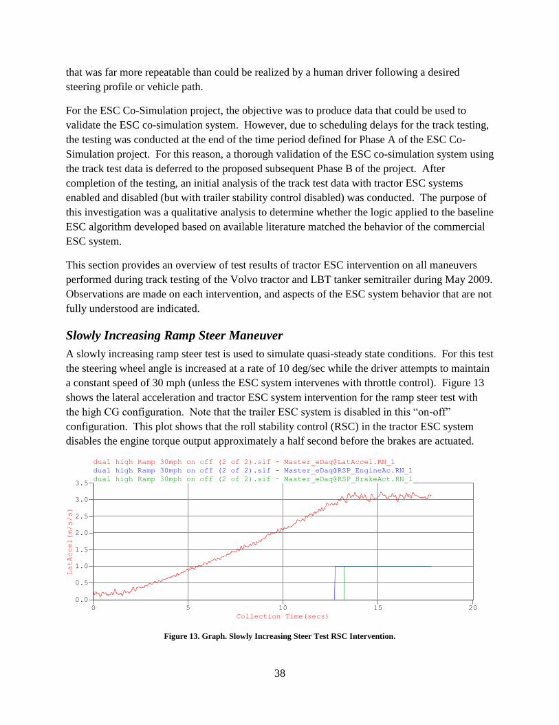
38
that was far more repeatable than could be realized by a human driver following a desired
steering profile or vehicle path.
For the ESC Co-Simulation project, the objective was to produce data that could be used to
validate the ESC co-simulation system. However, due to scheduling delays for the track testing,
the testing was conducted at the end of the time period defined for Phase A of the ESC Co-
Simulation project. For this reason, a thorough validation of the ESC co-simulation system using
the track test data is deferred to the proposed subsequent Phase B of the project. After
completion of the testing, an initial analysis of the track test data with tractor ESC systems
enabled and disabled (but with trailer stability control disabled) was conducted. The purpose of
this investigation was a qualitative analysis to determine whether the logic applied to the baseline
ESC algorithm developed based on available literature matched the behavior of the commercial
ESC system.
This section provides an overview of test results of tractor ESC intervention on all maneuvers
performed during track testing of the Volvo tractor and LBT tanker semitrailer during May 2009.
Observations are made on each intervention, and aspects of the ESC system behavior that are not
fully understood are indicated.
Slowly Increasing Ramp Steer Maneuver
A slowly increasing ramp steer test is used to simulate quasi-steady state conditions. For this test
the steering wheel angle is increased at a rate of 10 deg/sec while the driver attempts to maintain
a constant speed of 30 mph (unless the ESC system intervenes with throttle control). Figure 13
shows the lateral acceleration and tractor ESC system intervention for the ramp steer test with
the high CG configuration. Note that the trailer ESC system is disabled in this “on-off”
configuration. This plot shows that the roll stability control (RSC) in the tractor ESC system
disables the engine torque output approximately a half second before the brakes are actuated.
dual high Ramp 30mph on off (2 of 2).sif - [email protected]_1
Collection Time(secs)
0 5 10 15 20
LatAccel(m/s/s)
0.0
0.5
1.0
1.5
2.0
2.5
3.0
3.5
dual high Ramp 30mph on off (2 of 2).sif - Master_eDaq@RSP_EngineAc.RN_1
dual high Ramp 30mph on off (2 of 2).sif - Master_eDaq@RSP_BrakeAct.RN_1
Figure 13. Graph. Slowly Increasing Steer Test RSC Intervention.

39
All of the slowly increasing ramp steer tests consistently indicate a lateral acceleration of ~0.3 g
at tractor RSC intervention. The level of lateral acceleration before intervention is
approximately the same for both high and low CG cases. In the low CG case the RSC
application may be at slightly higher lateral acceleration, but this is difficult to say conclusively.
Figure 14 shows braking application at each wheel during ramp steer test. Here “LAX1PRES” is
the brake pressure at the left wheel of axle 1 (steer axle). Axle 3 is the tractor rear drive axle and
is not shown in the plot since both drive axles share common valves for the left and right sides
and therefore have the same pressures. Similarly LAX4PRES (brake pressure of left wheel of 4th
axle) is representative of the brake pressure at all four trailer wheels since only one valve
actuates all wheels. In the RSC intervention for the slowly increasing steer test the tractor brakes
are not applied. The reason for this is unknown, but one possible explanation is that the rollover
threshold for the fully loaded trailer is assumed to be much lower than that of the tractor.
Applying brakes to the trailer only would ensure that the tractor is not braked unnecessarily
when there is no trailer load (i.e. bobtail). However, since the trailer load is sensed by the
controller it is unclear why it would not brake the tractor as well in this situation. Note that the
trailer brakes appear to be pulsed at a frequency <1 Hz. It is not clear if this is normal ABS
operation in response to wheel slip or some other operation of the tractor ESC and/or ABS
systems.
dual high Ramp 30mph on off (2 of 2).sif - [email protected]_1
Collection Time(secs)
0 5 10 15 20
LAX1PRES(PSI)
-5
0
5
10
15
20
25
dual high Ramp 30mph on off (2 of 2).sif - [email protected]_1
dual high Ramp 30mph on off (2 of 2).sif - [email protected]_1
dual high Ramp 30mph on off (2 of 2).sif - [email protected]_1
dual high Ramp 30mph on off (2 of 2).sif - [email protected]_1
Figure 14. Graph. Slowly Increasing Steer Test Wheel-End Brake Pressures.
Step Steer Maneuver
The step steer test is a quick ramp in 1 second to 170 deg at a speed of 33 mph. The test is
conducted “dropped throttle” in the sense that the tractor is put in neutral and allowed to coast
while the steering robot and data acquisition trigger when the target speed is reached. Figure 15
shows high CG configuration step steer with tractor ESC on and trailer ESC off. Note that
lateral acceleration builds quickly as the steering wheel ramps. In this case the tractor RSC
system activates braking, but does not intervene in the engine. Presumably this is because the

40
test was conducted with “dropped throttle” and thus no torque was demanded of the engine
anyway.
dual high Step 33 mph on off (2 of 2).sif - [email protected]_1
Collection Time(secs)
0.0 0.5 1.0 1.5 2.0 2.5 3.0
LatAccel(m/s/s)
-1
0
1
2
3
4
5
dual high Step 33 mph on off (2 of 2).sif - Master_eDaq@RSP_EngineAc.RN_1
dual high Step 33 mph on off (2 of 2).sif - Master_eDaq@RSP_BrakeAct.RN_1
Figure 15. Graph. Step Steer Test RSC Intervention.
Note that the intervention occurs at much higher lateral acceleration than in the slowly increasing
ramp steer case. There are two possible explanations for this. First, there may simply be a dwell
time of ~0.3 seconds after the 0.3 g (3 m/s2) threshold is reached before the system intervenes.
This would be noticeable in the step steer case, but not in the slowly increasing steer case since it
is effectively a steady state test. An alternative possibility is that the system assumes a higher
rollover threshold for the tractor than that of the trailer. In the dynamic step steer test, the lateral
acceleration in the trailer lags that of the tractor significantly, as can be observed in Figure 16.
Although this lateral acceleration data is noisy and the sign is reversed from the signal returned
from the ECU, the lateral acceleration of the trailer clearly lags that of the tractor by about 0.5
seconds. At ~1.6 seconds when tractor ESC intervention begins as seen in Figure 15, Figure 16
shows that the trailer lateral acceleration is only at ~2 m/s^2.
dual high Step 33 mph on off (2 of 2).sif - [email protected]_1
Collection Time(secs)
0.0 0.5 1.0 1.5 2.0 2.5 3.0
tcAccLat(m/s²)
-8
-7
-6
-5
-4
-3
-2
-1
0
1dual high Step 33 mph on off (1 of 2).sif - [email protected]_1
Figure 16. Graph. Step Steer Test Tractor (Red) and Trailer (Blue) Lateral Acceleration.
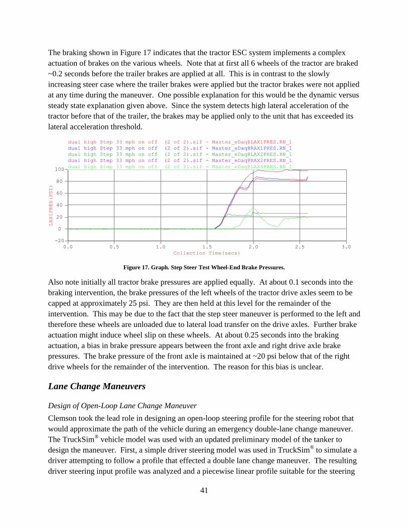
41
The braking shown in Figure 17 indicates that the tractor ESC system implements a complex
actuation of brakes on the various wheels. Note that at first all 6 wheels of the tractor are braked
~0.2 seconds before the trailer brakes are applied at all. This is in contrast to the slowly
increasing steer case where the trailer brakes were applied but the tractor brakes were not applied
at any time during the maneuver. One possible explanation for this would be the dynamic versus
steady state explanation given above. Since the system detects high lateral acceleration of the
tractor before that of the trailer, the brakes may be applied only to the unit that has exceeded its
lateral acceleration threshold.
dual high Step 33 mph on off (2 of 2).sif - [email protected]_1
Collection Time(secs)
0.0 0.5 1.0 1.5 2.0 2.5 3.0
LAX1PRES(PSI)
-20
0
20
40
60
80
100
dual high Step 33 mph on off (2 of 2).sif - [email protected]_1
dual high Step 33 mph on off (2 of 2).sif - [email protected]_1
dual high Step 33 mph on off (2 of 2).sif - [email protected]_1
dual high Step 33 mph on off (2 of 2).sif - [email protected]_1
Figure 17. Graph. Step Steer Test Wheel-End Brake Pressures.
Also note initially all tractor brake pressures are applied equally. At about 0.1 seconds into the
braking intervention, the brake pressures of the left wheels of the tractor drive axles seem to be
capped at approximately 25 psi. They are then held at this level for the remainder of the
intervention. This may be due to the fact that the step steer maneuver is performed to the left and
therefore these wheels are unloaded due to lateral load transfer on the drive axles. Further brake
actuation might induce wheel slip on these wheels. At about 0.25 seconds into the braking
actuation, a bias in brake pressure appears between the front axle and right drive axle brake
pressures. The brake pressure of the front axle is maintained at ~20 psi below that of the right
drive wheels for the remainder of the intervention. The reason for this bias is unclear.
Lane Change Maneuvers
Design of Open-Loop Lane Change Maneuver
Clemson took the lead role in designing an open-loop steering profile for the steering robot that
would approximate the path of the vehicle during an emergency double-lane change maneuver.
The TruckSim® vehicle model was used with an updated preliminary model of the tanker to
design the maneuver. First, a simple driver steering model was used in TruckSim®
to simulate a
driver attempting to follow a profile that effected a double lane change maneuver. The resulting
driver steering input profile was analyzed and a piecewise linear profile suitable for the steering
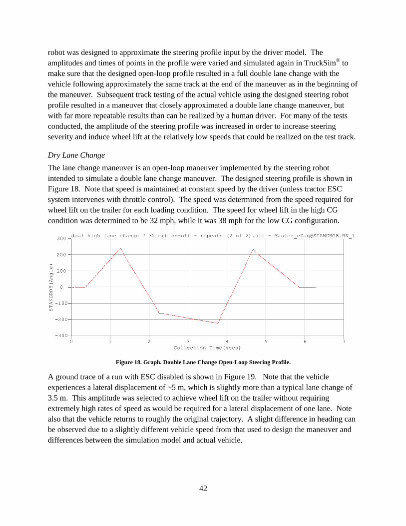
42
robot was designed to approximate the steering profile input by the driver model. The
amplitudes and times of points in the profile were varied and simulated again in TruckSim®
to
make sure that the designed open-loop profile resulted in a full double lane change with the
vehicle following approximately the same track at the end of the maneuver as in the beginning of
the maneuver. Subsequent track testing of the actual vehicle using the designed steering robot
profile resulted in a maneuver that closely approximated a double lane change maneuver, but
with far more repeatable results than can be realized by a human driver. For many of the tests
conducted, the amplitude of the steering profile was increased in order to increase steering
severity and induce wheel lift at the relatively low speeds that could be realized on the test track.
Dry Lane Change
The lane change maneuver is an open-loop maneuver implemented by the steering robot
intended to simulate a double lane change maneuver. The designed steering profile is shown in
Figure 18. Note that speed is maintained at constant speed by the driver (unless tractor ESC
system intervenes with throttle control). The speed was determined from the speed required for
wheel lift on the trailer for each loading condition. The speed for wheel lift in the high CG
condition was determined to be 32 mph, while it was 38 mph for the low CG configuration.
dual high lane change 7 32 mph on-off - repeats (2 of 2).sif - [email protected]_1
Collection Time(secs)
0 1 2 3 4 5 6 7
STANGROB(Angle)
-300
-200
-100
0
100
200
300
Figure 18. Graph. Double Lane Change Open-Loop Steering Profile.
A ground trace of a run with ESC disabled is shown in Figure 19. Note that the vehicle
experiences a lateral displacement of ~5 m, which is slightly more than a typical lane change of
3.5 m. This amplitude was selected to achieve wheel lift on the trailer without requiring
extremely high rates of speed as would be required for a lateral displacement of one lane. Note
also that the vehicle returns to roughly the original trajectory. A slight difference in heading can
be observed due to a slightly different vehicle speed from that used to design the maneuver and
differences between the simulation model and actual vehicle.

43
[email protected]_1 vs. [email protected]_1
tlPosXLo(m)
-40 -20 0 20 40 60 80
tlPosYLo(m)
-68
-67
-66
-65
-64
-63
-62
-61
Figure 19. Graph. Dry Double Lane Change Ground Track.
Dry Lane Change High CG Configuration
The activation of the tractor ESC (RSC) system during the dry lane change maneuver is shown in
Figure 20 and the wheel-end brake pressures are shown in Figure 21. The Yaw Stability Control
(YSC) algorithm of the tractor ESC system did not intervene in any of the tests on the dry
surface. During the first intervention, the behavior of the system is very similar to that of the
step steer maneuver, except that the engine and brake intervention are initiated simultaneously.
This can be attributed to the fact that the lane change maneuvers were implemented with throttle
input to maintain speed while the step steer test was conducted dropped throttle. The results
shown in these figures were very consistent over five repeat runs of this same lane change test.
During the first intervention the system performs as in the step steer: tractor brakes before trailer
brakes, cap on brake pressure to inside drive wheels and steer/drive axle brake bias at high
pressures. Notice that as the lateral acceleration reverses direction while ESC is still intervening,
the cap on the left drive wheel brake pressures is relaxed.
dual high lane change 7 32 mph on-off - repeats (2 of 2).sif - [email protected]_1
Collection Time(secs)
0 1 2 3 4 5 6 7
LatAccel(m/s/s)
-4
-2
0
2
4
6
dual high lane change 7 32 mph on-off - repeats (2 of 2).sif - Master_eDaq@RSP_EngineAc.RN_1
dual high lane change 7 32 mph on-off - repeats (2 of 2).sif - Master_eDaq@RSP_BrakeAct.RN_1
Figure 20. Graph. Dry Lane Change High CG Test RSC Intervention.

44
As the vehicle begins to initiate the return to the original lane, a second ESC intervention is
observed. In this case the engine intervention occurs before brake intervention as with the step
steer maneuver. During this second intervention, the tractor braking leads the trailer braking as
before, however at no time are the steer axle wheels braked. The reason for the lack of braking
of the steering wheels at this point in the maneuver is unknown. The drive axles are braked with
a slight bias to the left (now outside) wheels.
dual high lane change 7 32 mph on-off - repeats (2 of 2).sif - [email protected]_1
Collection Time(secs)
0 1 2 3 4 5 6 7
LAX1PRES(PSI)
-20
0
20
40
60
80
100
120
dual high lane change 7 32 mph on-off - repeats (2 of 2).sif - [email protected]_1
dual high lane change 7 32 mph on-off - repeats (2 of 2).sif - [email protected]_1
dual high lane change 7 32 mph on-off - repeats (2 of 2).sif - [email protected]_1
dual high lane change 7 32 mph on-off - repeats (2 of 2).sif - [email protected]_1
Figure 21. Graph. Dry Lane Change High CG Test Wheel-End Brake Pressures.
Dry Lane Change Low CG Configuration
Figure 22 and Figure 23 show similar plots for the dry lane change maneuver for the low CG
configuration. While the brake pressures for the first tractor ESC intervention are similar to
those of the high CG configuration, the brake actuation during the second intervention is
significantly different in nature. This is likely primarily due to the fact that the driver attempts to
maintain 38 mph instead of 32 mph, however the reasons for this different brake actuation are
unclear. In the low CG case, the steer axle and left (outside) drive axle wheel brakes actuate
with a bias to the steer axle. In this case the right (inside) drive axle wheels are not braked at all.
Note that these observed differences in the second ESC intervention were consistent among
repeated tests of both the high and low CG configurations. Obviously there is some complex
logic used to decide the levels of brake activation to individual wheels that is not immediately
understood without access to the proprietary data of the ESC supplier. The differences may be
due to the understeer/oversteer conditions of the vehicle during the second ESC intervention.

45
dual low lane change 7 38 mph on-off - repeats (2 of 2).sif - [email protected]_6
Collection Time(secs)
0 1 2 3 4 5 6 7 8
LatAccel(m/s/s)
-4
-2
0
2
4
6
dual low lane change 7 38 mph on-off - repeats (2 of 2).sif - Master_eDaq@RSP_EngineAc.RN_6
dual low lane change 7 38 mph on-off - repeats (2 of 2).sif - Master_eDaq@RSP_BrakeAct.RN_6
Figure 22. Graph. Dry Lane Change Low CG Test RSC Intervention.
dual low lane change 7 38 mph on-off - repeats (2 of 2).sif - [email protected]_6
Collection Time(secs)
0 1 2 3 4 5 6 7 8
LAX1PRES(PSI)
-20
0
20
40
60
80
100
120
dual low lane change 7 38 mph on-off - repeats (2 of 2).sif - [email protected]_6
dual low lane change 7 38 mph on-off - repeats (2 of 2).sif - [email protected]_6
dual low lane change 7 38 mph on-off - repeats (2 of 2).sif - [email protected]_6
dual low lane change 7 38 mph on-off - repeats (2 of 2).sif - [email protected]_6
Figure 23. Graph. Dry Lane Change Low CG Test Wheel-End Brake Pressures.
Wet Lane Change
The wet lane change maneuver is similar to the dry lane change maneuver except that it is
executed on a wet Jennite surface that has a reported coefficient of friction of ~0.3. The
objective of this test is to activate the yaw stability control (YSC) part of the ESC system.
Again, an open-loop maneuver implemented by the steering robot is used to simulate a double
lane change maneuver. The designed steering profile is shown in Figure 26. The wet tests were
conducted as “dropped throttle” tests to increase consistency. The profile amplitude was
increased significantly compared to the dry tests in order to induce understeer/oversteer effects at
relatively low speeds. This was primarily due to physical size constraints of the wet Jennite pad
used for testing.
Unfortunately, the wet Jennite pad did not have a low enough coefficient of friction to
consistently induce yaw instability without excessive lateral acceleration. As a result, the roll
stability control was almost always activated during test runs in which yaw stability control was
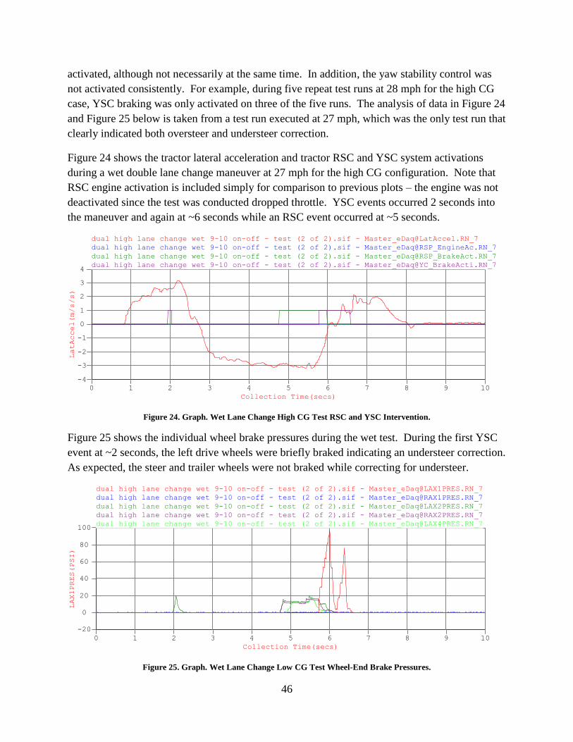
46
activated, although not necessarily at the same time. In addition, the yaw stability control was
not activated consistently. For example, during five repeat test runs at 28 mph for the high CG
case, YSC braking was only activated on three of the five runs. The analysis of data in Figure 24
and Figure 25 below is taken from a test run executed at 27 mph, which was the only test run that
clearly indicated both oversteer and understeer correction.
Figure 24 shows the tractor lateral acceleration and tractor RSC and YSC system activations
during a wet double lane change maneuver at 27 mph for the high CG configuration. Note that
RSC engine activation is included simply for comparison to previous plots – the engine was not
deactivated since the test was conducted dropped throttle. YSC events occurred 2 seconds into
the maneuver and again at ~6 seconds while an RSC event occurred at ~5 seconds.
dual high lane change wet 9-10 on-off - test (2 of 2).sif - [email protected]_7
Collection Time(secs)
0 1 2 3 4 5 6 7 8 9 10
LatAccel(m/s/s)
-4
-3
-2
-1
0
1
2
3
4
dual high lane change wet 9-10 on-off - test (2 of 2).sif - Master_eDaq@RSP_EngineAc.RN_7
dual high lane change wet 9-10 on-off - test (2 of 2).sif - Master_eDaq@RSP_BrakeAct.RN_7
dual high lane change wet 9-10 on-off - test (2 of 2).sif - Master_eDaq@YC_BrakeActi.RN_7
Figure 24. Graph. Wet Lane Change High CG Test RSC and YSC Intervention.
Figure 25 shows the individual wheel brake pressures during the wet test. During the first YSC
event at ~2 seconds, the left drive wheels were briefly braked indicating an understeer correction.
As expected, the steer and trailer wheels were not braked while correcting for understeer.
dual high lane change wet 9-10 on-off - test (2 of 2).sif - [email protected]_7
Collection Time(secs)
0 1 2 3 4 5 6 7 8 9 10
LAX1PRES(PSI)
-20
0
20
40
60
80
100
dual high lane change wet 9-10 on-off - test (2 of 2).sif - [email protected]_7
dual high lane change wet 9-10 on-off - test (2 of 2).sif - [email protected]_7
dual high lane change wet 9-10 on-off - test (2 of 2).sif - [email protected]_7
dual high lane change wet 9-10 on-off - test (2 of 2).sif - [email protected]_7
Figure 25. Graph. Wet Lane Change Low CG Test Wheel-End Brake Pressures.

47
Figure 26 shows the ESC system yaw rate sensor signal and measured lateral velocity during the
maneuver. (Note that the yaw rate sensor signal was incorrectly labeled simply “Yaw” in the
data acquisition system.) A significant lag in the buildup of yaw rate seems to trigger the
understeer correction.
dual high lane change wet 9-10 on-off - test (2 of 2).sif - [email protected]_7
STANGROB(Angle)
-400-300-200-1000100200300400
dual high lane change wet 9-10 on-off - test (2 of 2).sif - [email protected]_7
Yaw(radians/s)
-0.4-0.3-0.2-0.10.00.10.20.30.4
dual high lane change wet 9-10 on-off - test (2 of 2).sif - [email protected]_7
tcVelLat(m/s)
-2.0
-1.5
-1.0
-0.5
0.0
0.5
dual high lane change wet 9-10 on-off - test (2 of 2).sif - Master_eDaq@YC_BrakeActi.RN_7
Collection Time(secs)
0 1 2 3 4 5 6 7 8 9 10
YC_BrakeActi
0.0
0.2
0.4
0.6
0.8
1.0
Figure 26. Graph. Wet Lane Change High CG Test Tractor States and YSC Intervention.
A sustained lateral acceleration of -3 m/s seems to have triggered the RSC event. The braking
actuation during this event is very similar to that of the second intervention on the high CG
configuration/dry lane change maneuver. The steer axle brakes are not applied, but the drive
axles are braked followed by the trailer axles. There is a slight bias towards the left (outside)
drive wheel, but this bias changes to the right drive wheel momentarily at times during the
intervention as the braking levels increase or decrease.
At ~5.8 seconds into the maneuver a second YSC intervention occurs during which the left steer
wheel is braked, indicating an oversteer correction. In Figure 26 two factors seem to contribute
to the oversteer condition. First, the yaw rate to the right continues to increase even as the
steering wheel angle is decreased starting at 5.2 seconds. Second, there is a significant increase
in lateral velocity of the tractor prior to the YSC intervention. If the ESC controller estimates
lateral velocity and/or vehicle sideslip, this may be a condition that triggers the oversteer
correction. Note that in this particular maneuver the braking of the drive axles during RSC
intervention may actually induce the vehicle sideslip and thus the subsequent oversteer
correction of the YSC system. It is interesting to note that during the oversteer intervention, the
ESC system does not apply the trailer brakes. Bendix advertises that during jackknife prevention

48
both the outside steer wheel and trailer wheels are braked. However, it is possible that in this
case the system detected an oversteer condition of the tractor but not an impending jackknife
situation in which the trailer is also understeering.
Comparison of Vehicle States on Wet and Dry Maneuvers
Most electronic stability control system algorithms described in the literature operate on
deviations of vehicle states from expected states as determined from a simple vehicle model. To
evaluate the effectiveness of these state comparisons, relevant vehicle states are compared in this
section for the same lane change maneuver on both wet and dry surfaces. These tests were
conducted with tractor and trailer ESC systems disabled with a “dropped throttle” maneuver
triggered at 27 mph. Figure 27 and Figure 28 show the steer input and vehicle speed during both
maneuvers, which can be observed to be very consistent between the tests. Note that although in
these figures the file names seem to indicate different initial speeds, both runs shown were
executed with an initial speed of 27 mph. Also, in the file names the ESC naming convention
“off-off” indicates that both tractor ESC and trailer ESC were disabled. The file name for wet
maneuvers has a designation “xxx-off” indicating that the file contains some runs with tractor
ESC enabled and some with tractor ESC disabled, although the specific run shown has tractor
ESC disabled.
dual high lane change dry 9 28 mph off-off - test (2 of 2).sif - [email protected]_4
Collection Time(secs)
0 1 2 3 4 5 6 7 8 9 10
STANGROB(Angle)
-400
-300
-200
-100
0
100
200
300
400dual high lane change wet 9 27 mph xxx-off - test (2 of 2).sif - [email protected]_4
Figure 27. Graph. Dry and Wet Lane Change Steering Input Comparison.

49
dual high lane change dry 9 28 mph off-off - test (2 of 2).sif - [email protected]_4
Collection Time(secs)
0 1 2 3 4 5 6 7 8 9 10
VehicleSpdWh(km/h)
0
5
10
15
20
25
30
35
40
45dual high lane change wet 9 27 mph xxx-off - test (2 of 2).sif - [email protected]_4
Figure 28. Graph. Dry and Wet Lane Change Vehicle Speed Comparison.
Figure 29 through Figure 33 show various vehicle states as measured by both the tractor ESC
system sensors and external data acquisition systems during the manuevers. Note that a
comparison of tractor lateral velocity is not included in the plots provided. Unfortunately, there
was an error in the tractor inertial/GPS sensor unit during these wet tests that resulted in
corrupted data. However, the trailer inertial/GPS sensor unit did work properly and a
comparison of trailer lateral velocity is included.
dual high lane change dry 9 28 mph off-off - test (2 of 2).sif - [email protected]_4
Collection Time(secs)
0 1 2 3 4 5 6 7 8 9 10
Yaw(radians/s)
-0.4
-0.2
0.0
0.2
0.4
0.6dual high lane change wet 9 27 mph xxx-off - test (2 of 2).sif - [email protected]_4
Figure 29. Graph. Dry and Wet Lane Change Tractor Yaw Rate Comparison.

50
dual high lane change dry 9 28 mph off-off - test (2 of 2).sif - [email protected]_4
Collection Time(secs)
0 1 2 3 4 5 6 7 8 9 10
LatAccel(m/s/s)
-6
-4
-2
0
2
4
6dual high lane change wet 9 27 mph xxx-off - test (2 of 2).sif - [email protected]_4
Figure 30. Graph. Dry and Wet Lane Change Tractor Lateral Acceleration Comparison.
dual high lane change dry 9 28 mph off-off - test (2 of 2).sif - [email protected]_4
Collection Time(secs)
0 1 2 3 4 5 6 7 8 9 10
ARTICANG(DEG)
-30
-20
-10
0
10
20dual high lane change wet 9 27 mph xxx-off - test (2 of 2).sif - [email protected]_4
Figure 31. Graph. Dry and Wet Lane Change Trailer Articulation Angle Comparison.
dual high lane change dry 9 28 mph off-off - test (1 of 2).sif - [email protected]_4
Collection Time(secs)
0 1 2 3 4 5 6 7 8 9 10
tlAccLat(m/s²)
-6
-4
-2
0
2
4
6dual high lane change wet 9 27 mph xxx-off - test (1 of 2).sif - [email protected]_4
Figure 32. Graph. Dry and Wet Lane Change Trailer Lateral Acceleration Comparison.
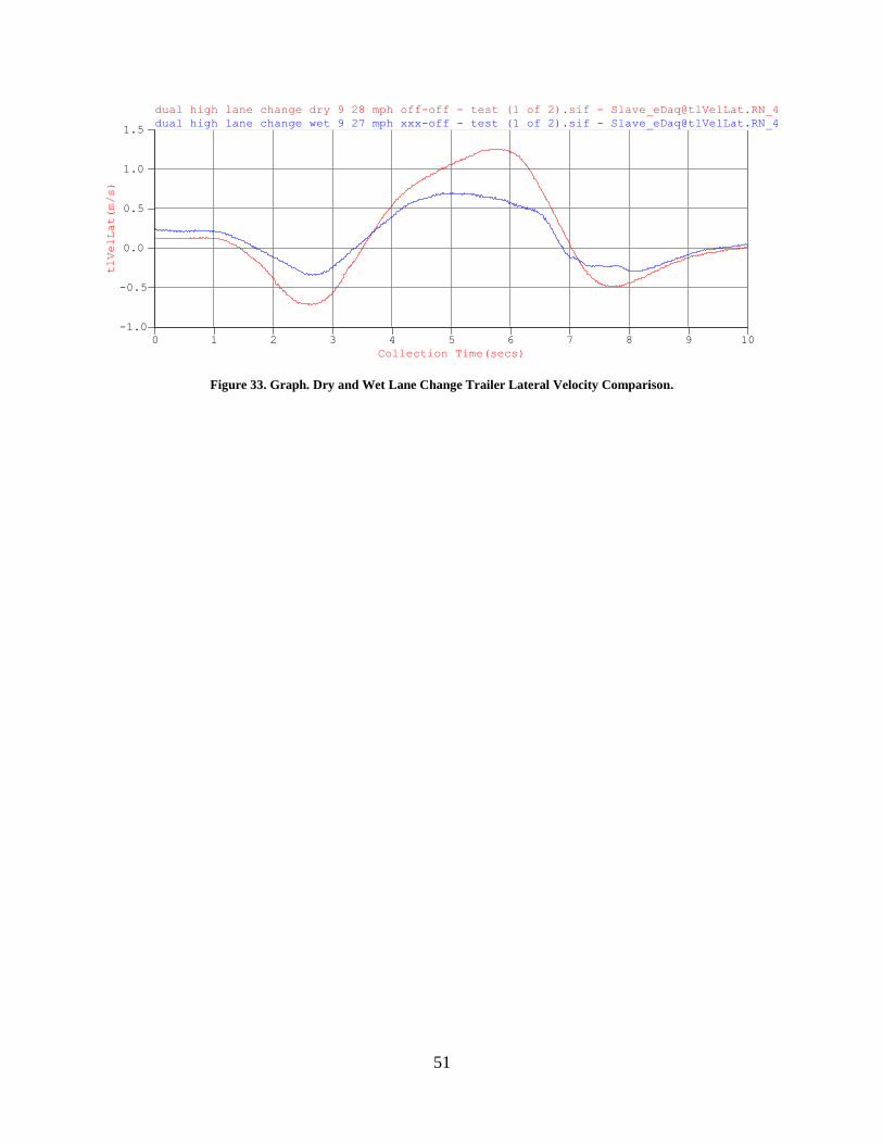
51
dual high lane change dry 9 28 mph off-off - test (1 of 2).sif - [email protected]_4
Collection Time(secs)
0 1 2 3 4 5 6 7 8 9 10
tlVelLat(m/s)
-1.0
-0.5
0.0
0.5
1.0
1.5dual high lane change wet 9 27 mph xxx-off - test (1 of 2).sif - [email protected]_4
Figure 33. Graph. Dry and Wet Lane Change Trailer Lateral Velocity Comparison.

52

53
Chapter 5 – Conclusion
This report summarizes the findings of the initial Phase A of NTRCI project U13: Co-Simulation
of Heavy Truck Tire Dynamics and Electronic Stability Control System. This project was led by
Clemson University with significant engineering support from Michelin Americas Research
Company and funding and equipment support from National Instruments. A review of existing
literature on the state of the art of ESC systems for articulated heavy trucks was conducted. The
requirements for a Hardware-In-the-Loop (HIL) system for heavy truck ESC systems were
investigated. A co-simulation platform was developed using LabVIEW™
and TruckSim® for the
investigation of ESC control algorithms. An ESC algorithm was developed and simulated using
the co-simulation system described. In addition, track testing of an ESC-equipped heavy tractor
and tanker semi-trailer was conducted in conjunction with Heavy Truck Rollover
Characterization project participants. Data from the track testing was analyzed to characterize
the commercial ESC system equipped on the Volvo test tractor.
The review of the literature on heavy truck ESC systems showed a fairly common basis of
approach to stability control strategies. However, various approaches described used different
vehicle states for feedback control. Many of these states are not measured on state-of-the-art
commercial systems, such as trailer articulation angle and angular rate. While the literature
shows how some unmeasured states such as lateral velocity may be estimated, little consideration
is given to other states such as articulation and roll angles. Therefore the algorithms presented in
the available literature are of limited use in developing an algorithm that is truly representative of
a commercial system. Many assumptions must be made about the implementation in the
commercial systems in order to simulate their behavior.
The investigation of the HIL simulation system revealed that successful implementation requires
information about the ESC system and controller that is not publicly available. In general this
implies that successful HIL simulation can only be realized with support from the ESC system
supplier. The primary areas of information required are in the requirements of the diagnostic
systems within the controller and the CAN-bus protocols used for communication between
system sensors and the electronic control unit.
A key finding in the development of an algorithm for ESC system co-simulation is the need for
an accurate linear reference model of vehicle dynamics. The standard linear “articulated
bicycle” handling model found in the literature was found to be insufficient to accurately reflect
the vehicle states during handling maneuvers, even in steady state conditions. Further
investigation yielded three factors that contributed significantly to the vehicle handling
dynamics: axle roll steer, lateral force compliance steer, and aligning moment compliance steer.
Models of each of these effects were developed and successfully incorporated into an enhanced
linear handling model. The resulting model was found to track vehicle states of the complete
nonlinear TruckSim® model accurately both under transient and steady state conditions. A state
54
feedback controller for yaw stability based on this model was developed and implemented. The
system was found to qualitatively represent the dynamics of the commercial ESC system.
Further simulation, analysis and calibration of the system would be required to quantitatively
represent the behavior of the commercial system with the co-simulation system. Support from
the commercial ESC system supplier would also likely be required to successfully emulate the
behavior of the system.
Analysis of track test data resulted in identification of a number of nuances of the commercial
system that are not well understood. In general the system performed as expected in keeping the
vehicle under control during roll or yaw instability events. However, the strategy, timing and
actuation of individual wheel activations could not be discerned completely from the tests
conducted. In addition, the interaction of ESC and ABS systems could not be fully separated
from the measured data. In order to fully characterize the system, exhaustive track testing would
need to be conducted. It is recommended that should the HIL or co-simulation systems be
pursued further, the support of the system supplier Bendix should be sought to provide the
missing information needed.
As a continuation of this project, a proposed Phase B entails the investigation of advanced ESC
system approaches. Such research would utilize the ESC co-simulation system developed in
Phase A of the project to further study advancements in sensors, tractor-trailer communication,
and algorithms for ESC. This proposed research would support the efforts of the Heavy Truck
Rollover Characterization project, which aims to include the design of a demonstrator truck for
technologies that enhance vehicle stability with regard to rollover. The ESC system is an
integral part of the stability equation, and enhancements designed in Phase B of this project
could ultimately be integrated into the HTRC demonstrator truck.
55
Chapter 6 - References
1. Genta, G., Motor Vehicle Dynamics : Modeling and Simulation. Series on Advances in
Mathematics for Applied Sciences. Vol. 43. 1997, Singapore; River Edge, N.J.: World
Scientific. 539.
2. Ghoneim, Y.A., et al., Integrated chassis control system to enhance vehicle stability. Int.
J. of Vehicle Design, 2000. 23(1/2).
3. Tseng, H.E., et al., The Development of Vehicle Stability Control at Ford. IEEE/ASME
Transactions on Mechatronics, 1999. 4(3).
4. Manning, W.J. and D.A. Crolla, A review of yaw rate and sideslip controllers for
passenger vehicles. Transactions of the Institute of Measurement and Control, 2007.
29(2): p. 117–135.
5. Shibahata, Y., K. Shimada, and T. Tomari, Improvement of Vehicle Maneuverability by
Direct Yaw Moment Control. Vehicle System Dynamics, 1993. 22: p. 465-481.
6. van Zanten, A.T., Bosch ESP Systems: 5 Years of Experience. SAE Paper 2000-01-1633,
2000.
7. van Zanten, A.T., et al., VDC Systems Development and Perspective. SAE Paper 980235,
1998.
8. van Zanten, A.T., R. Erhardt, and G. Pfaff, VDC, The Vehicle Dynamics Control System
of Bosch. SAE Paper 950759, 1995.
9. Bedner, E., D. Fulk, and A. Hac, Exploring the Trade-Off of Handling Stability and
Responsiveness With Advanced Control Systems. SAE Paper 2007-01-0812, 2007.
10. Esmailzadeh, E., A. Goodarzi, and G.R. Vossoughi, Optimal yaw moment control law for
improved vehicle handling. Mechatronics, 2003. 13(7): p. 659-675.
11. Zheng, S., et al., Controller design for vehicle stability enhancement. Control
Engineering Practice, 2006. 14(12): p. 1413-1421.
12. Anwar, S., Generalized predictive control of yaw dynamics of a hybrid brake-by-wire
equipped vehicle. Mechatronics, 2005. 15(9): p. 1089-1108.
13. Eslamian, M., G. Alizadeh, and M. Mirzaei, Optimization-based non-linear yaw moment
control law for stabilizing vehicle lateral dynamics. Proceedings of the Institution of
Mechanical Engineers, Part D: Journal of Automobile Engineering, 2007. 221.
14. Yi, K., et al., An investigation into differential braking strategies for vehicle stability
control. Proceedings of the Institution of Mechanical Engineers, Part D: Journal of
Automobile Engineering, 203. 217.
15. Abe, M., et al., Side-slip control to stabilize vehicle lateral motion by direct yaw moment.
JSAE Review, 2001. 22(4): p. 413-419.
16. Rajamani, R., Vehicle Dynamics and Control. 2006, New York: Springer Science. 470.
17. Wielenga, T.J., A Method for Reducing On-Road Rollovers ± Anti-Rollover Braking.
SAE Paper 1999-01-0123, 1999.
18. Hecker, F., et al., Vehicle Dynamics Control for Commercial Vehicles. SAE Paper
973284, 1997.
19. Eisele, D.D. and H. Peng. Vehicle Dynamics Control With Rollover Prevention for
Articulated Heavy Trucks. in Proceedings of AVEC 2000 5th Int'l Symposium on
Advanced Vehicle Control 2000. Ann Arbor, Michigan.

56
20. Palkovics, L., Á. Semsey, and E. Gerum, Roll-Over Prevention System for Commercial
Vehicles–Additional Sensorless Function of the Electronic Brake System. Vehicle System
Dynamics, 1999. 32(4): p. 285-297.
21. Petersen, E., et al., Vehicle Stability Control for Trucks and Buses. SAE Paper 982782,
1998.
22. Kang, X. and W. Deng, Vehicle-Trailer Handling Dynamics and Stability Control-an
Engineering Review. SAE Paper 2007-01-822, 2007.
23. Bendix. Electronic Controls Brochure. 2008 [cited; Available from:
http://www.bendix.com/SiteCollectionDocuments/ABS/ElectronicControlsBrochure.pdf.
24. Oh, P., H. Zhou, and K. Pavlov, Stability Control of Combination Vehicle. SAE Paper
2001-01-0138, 2001.
25. Mokhiamar, O. and M. Abe, Examination of different models following types of yaw
moment control strategy for improving handling safety of a car-caravan combination.
Proceedings of the Institution of Mechanical Engineers, Part D: Journal of Automobile
Engineering, 2005. 217(7): p. 561-571.
26. Jindra, F., Handling Characteristics of Tractor-Trailer Combinations. SAE Paper
650720, 1965.
27. Chen, C. and M. Tomizuka, Lateral Control of Commercial Heavy Vehicles. Vehicle
System Dynamics, 2000. 33(6): p. 391-420.
28. Gäfvert, M. and O. Lindgärde, A 9-DOF Tractor-Semitrailer Dynamic Handling Model
for Advanced Chassis Control Studies. Vehicle System Dynamics, 2004. 41(1): p. 51-82.
29. Law, E.H. and I. Janajreh, Effects of Tire and Vehicle Design Characteristics on Rollover
of Tractor Semi-Trailers. SAE Paper 2004-01-1739, 2004.
30. TruckSim 7: Math Models. 2008 [cited; Available from:
http://www.carsim.com/downloads/pdf/Math_Models_T7.pdf.
31. SIMPACK®
Automotive Data Sheet. 2008 [cited; Available from:
http://www.simpack®.com/downloads/pdf/datasheet_automotive.pdf.

A-1
Appendix A
Literature Review
This section provides an overview of the current literature relevant to this project. This fulfills
the deliverable task outlined as Task 2 in the project proposal. First, an overview of ESC
systems for passenger vehicles and heavy trucks is provided. Then the truck models used for
simulation of handling dynamics are investigated.
Electronic Stability Control Algorithms
Electronic stability control is currently implemented in many production passenger vehicles [2,
3]. In passenger vehicles the electronic stability control system is used to prevent spin-out and to
match the vehicle yaw rate response to the intent of the driver. The value of peak friction
coefficient, μ, at which un-tripped rollover may occur in passenger vehicles is 1.1 to 1.7, whereas
this value is in the range 0.4 to 0.8 for heavy and medium trucks [1]. Thus while passenger cars
will tend to spin or plow out (limit oversteer or understeer) at the limits of stability, heavy trucks
are much more likely to roll over. Rollover accidents tend to be significantly more fatal and
costly than other types of accidents, especially in the case of heavy trucks. For this reason
electronic stability control in heavy trucks provides the additional safety function of rollover
prevention.
ESC for Passenger Vehicles
The fundamental concept of current ESC systems is the use of differential braking to apply a yaw
moment to the vehicle in order to ensure the vehicle follows the path indicated by the driver
steering input. Actuation is accomplished by the use of hydraulic valves in the braking system
that are also used for Anti-lock Braking System (ABS) functionality [4-8]. Sensors used by
these systems typically use a steering wheel angle sensor, individual wheel speed sensors, a
lateral accelerometer and a yaw rate sensor[8].
It should be noted that ESC affects both vehicle handling stability and responsiveness, and often
the design of the system involves a trade-off between the two[9]. One objective of this research
is to match the model used for determining driver intent to the actual physical system in order to
reduce the compromise in vehicle responsiveness due to the ESC system.
The general form of a typical ESC control scheme is shown in Figure A- 1. The current state
vector x of the vehicle is determined from the measurements of the set of sensors described
above. Some parameters such as the sideslip cannot be measured directly, and instead must be
estimated from the various sensor values. One challenge to estimating sideslip is that the road
bank angle causes a bias in the lateral accelerometer measurement. One algorithm for estimating
road bank angle and compensating the lateral acceleration measurement is proposed in Tseng [3].

A-2
The desired states are typically determined from the measured steering wheel angle either by a
linear state space dynamic model or a steady state model of the vehicle. Lookup tables are
typically used to vary the model parameters with vehicle speed. The desired states are then
compared to the measured and estimated states. Typically, a deadband function is employed to
ensure that activation of the system only occurs when there is significant deviation between the
desired and the measured state values. Some form of transfer function may then be applied to
the error signal to determine the demanded moment to the lower-level system that implements
differential braking. For example, in the case of full-state feedback control, this transfer function
is simply a set of gains applied to the error signal [10, 11]. The output is generally differential
braking pressures applied per axle or individual brake torques applied at each wheel [2, 11].
Figure A- 1. Diagram. Basic ESC High-Level Control Structure.
The most common form of feedback control for ESC is the full-state feedback Linear Quadratic
Regulator (LQR) [10, 11]. Such a design automatically places the poles of the closed loop
system such that a cost function with weighted Q and R matrices to be applied to the state errors
and control outputs respectively is minimized. Alternatively, if only a single variable is used for
feedback such as yaw rate, a simple PD controller may be used to place the closed loop poles at a
desired location[2].
One approach applied by Anwar [12] is a model-predictive controller for yaw control. Another
optimization-based approach is described by Eslamian [13]. This approach uses an optimization
to design a non-linear controller for side-slip regulation. Sliding mode control is yet another
approach that has been used to address the stability control problem [14-16].

A-3
It should be noted that differential braking has been employed on passenger vehicles for
functions other than yaw rate and sideslip tracking. Wielenga [17] has proposed an “anti-
rollover braking” scheme which uses differential braking to avoid rollover in vehicles with a
relatively high center of gravity. In high sideslip conditions, such a vehicle is prone to rollover
instead of spinning or plowing out as would a normal passenger car. Braking applied to the front
outside wheel in such a condition will slow the vehicle and provide a moment to reduce the
vehicle sideslip. It should be noted, however, that while such a system might mitigate the risk of
rollover, the vehicle will not necessarily track the direction intended by the driver and may still
leave the roadway and result in an accident. However, rollover is a serious concern for heavy
trucks, and as will be seen, such a scheme may be used to augment the normal ESC operation in
applications for heavy trucks.
ESC for Articulated Heavy Trucks
Increasingly, new heavy trucks are being equipped with electronic driver aids such as ESC
systems to augment driver input and ensure vehicle stability in extreme maneuvers. Several
approaches similar to the implementation of ESC on passenger vehicles have been proposed for
heavy trucks in the literature [18-21].
The handling dynamics of a vehicle with an articulated trailer differ significantly from the
dynamics of a single rigid-body vehicle. The following are some of the unique characteristics of
the articulated vehicle-trailer combination [22]:
Smaller stability region in yaw and roll modes at high speed
Jackknifing and trailer swing phenomena
Lateral trailer oscillation, possibly self-excited
Phase lag between vehicle and trailer motions
Rearward amplification: highest peak lateral acceleration at the rearmost trailer
Unstable reverse motion
The smaller stability region in yaw and roll modes corresponds to the addition of the trailer
dynamics as compared to a single rigid vehicle. The addition of the trailer adds a pole pair to the
dynamics with significantly lower damping ratio and natural frequency than that of the vehicle
dynamics alone [22].
Similar to the pole pair corresponding to the vehicle yaw dynamics, the trailer pole pair moves
closer to the imaginary axis with increasing vehicle speed. Thus instability in the trailer mode is
reached at lower speed than the instability in the vehicle mode.
Under large lateral accelerations, heavy trucks are more prone to rollover while passenger cars
are more likely to spin or plow out. This is due to the relatively high center of gravity relative to
the vehicle track width [1]. The stability control systems for passenger cars are focused on
correcting oversteer or understeer conditions. However, the objective of stability control systems

A-4
for articulated heavy trucks is often augmented to address other concerns such as jackknifing or
rollover.
The operating concept of a commercial tractor-trailer stability control system is shown in Figures
2-4 [23]. A jackknife condition may occur when the tractor unit yaw angle is greater than that
desired by the driver, resulting in excessive tractor sideslip and trailer articulation angle. Such a
condition may lead to instability and loss of control of the vehicle. As shown in Figure A- 2,
commercial stability control systems intervene in the case of jackknifing by braking the outside
front wheel of the tractor and by braking the trailer.
Figure A- 2. Illustration. Jackknife (Oversteer) Mitigation [23].
Rollover conditions may occur when the lateral acceleration of the vehicle is high enough to
produce sufficient roll to reduce the normal force on the inside tires to zero as shown in Figure
A- 3. Such a condition is mitigated by the stability control system by braking all wheels of the
tractor and trailer if possible. The maximum braking force is used to reduce vehicle forward
velocity and thus lateral acceleration as much as possible to prevent rollover [23]. This is shown
in Figure A- 4.
Figure A- 3. Illustration. Rollover Condition [23].

A-5
Figure A- 4. Illustration. Rollover Mitigation [23].
A number of applications of ESC to combination vehicles are found in the literature. Some are
applied to passenger cars that may be used to tow a trailer [22, 24, 25]. In this case the controller
usually attempts to ensure that the vehicle states track the model of a nominal vehicle without a
trailer. Other systems have been designed specifically for articulated tractor-trailer combinations
[18-21].
The application of the Bosch vehicle dynamics control system to articulated commercial vehicles
was presented in Hecker [18]. This system uses a steady state model based on the articulated
bicycle model to determine desired states for yaw rate, sideslip and trailer angle for a given steer
input. The trailer articulation angle is then used as a feedback variable in the ESC scheme;
however, no mention is made of how this angle is sensed by the system. One significant point
made in Hecker [18] is that the model used for desired states must be adjusted for the variable
loading conditions unique to heavy trucks. While mention is made that the system identifies the
vehicle mass and adapts the model accordingly, no explanation is provided regarding the method
of estimation used. Such an adaptation is the primary focus of the current proposed research
project.
Another approach to ESC control of an articulated heavy truck is presented in Eisele and Peng
[19]. This system adds roll control to the normal oversteer and understeer objectives of the
controller. In addition to normal yaw rate and sideslip feedback control, roll control is provided
by feedback terms applied to roll angle, roll rate and lateral acceleration. Feedback control of the
trailer angle is not considered in this ESC algorithm. Simulations of fishhook maneuvers
demonstrate the capability of the system to avoid rollover.
Articulated Truck Models for Handling Simulation
A number of models have been developed for the purposes of simulation of handling maneuvers
of articulated trucks, with model fidelity ranging from simple to very complex. The simplest of
these is the three degree-of-freedom (3 DOF) linearized articulated bicycle or “tricycle” model
originally developed by Jindra [26]. This model is commonly used for eigenvalue analysis,
control design and determination of the desired states in the ESC controller. Non-linear
formulations of between 4 and 9 DOF may be used to provide more accurate simulations of

A-6
actual vehicle performance. In addition, commercial tools such as TruckSim® or SIMPACK
®
provide very high fidelity models of the complete combination vehicle non-linear dynamics, and
provide extensions for application in real-time Hardware-In-the-Loop (HIL) application.
Analytical Truck Models
A general non-linear 4-DOF model of the articulated truck can be readily derived for the basic
lateral dynamics of the vehicle. In Genta [1], such a model is derived using a Lagrange
formulation of the equations of motion. The tractor and trailer are treated as rigid bodies, and the
four degrees of freedom are:
Forward motion
Lateral motion
Yaw angle
Trailer articulation angle
A more accurate model of the vehicle dynamics may be realized by adding a roll degree of
freedom. There is significant interaction between the roll and yaw dynamics; therefore, the
addition of the roll degree of freedom allows higher fidelity simulation of the vehicle lateral
handling. Such a model is proposed in Chen and Tomizuka [27]. The model presented is a 5-
DOF model where the trailer and tractor share a common roll axis. It should be noted that the
common roll axis constraint is not physically realizable in the case where there is an articulation
angle between the tractor and trailer. As explained in Gäfvert and Lindgärde [28], in this case
either the tractor or trailer must be allowed to rotate in a pitch motion to realize the fifth-wheel
hitch constraint. However the common roll angle approximation provides a simple model that
reasonably represents the physical system under normal conditions.
A more complete model of the vehicle is realized in Gäfvert and Lindgärde [28] by also
considering the pitch and heave motions of the tractor and trailer. A common roll angle between
the tractor and trailer is still assumed, therefore the complete system is a 9-DOF model. The
large number of terms in the non-linear model equations are managed by assembling the model
with the aid of a Maple program. The Maple program handles all of the algebraic manipulations
in the derivations of the equations of motion from the constitutive equations, and is capable of
directly generating C code of the final equations. In this manner the model C code may be called
from a simulation tool such as Simulink for the purpose of simulating vehicle motion.
In Gäfvert and Lindgärde [28], the claim is made that the pitch and heave degrees of freedom are
necessary for the simulation of the articulated vehicle for handling maneuvers such as testing
ESC algorithms. To this end a comparison is made between simulation output of the 9-DOF
model and a linearized 3-DOF model. However, it is unclear that such a 9-DOF model has
significantly higher accuracy than a 4 or 5-DOF nonlinear model, as these models are not
included in the comparison. Therefore the increased model complexity of the 9-DOF model may
not be warranted for the simulation of handling maneuvers.

A-7
It should be noted that the fifth wheel connection introduces a significant nonlinearity between
the tractor and the trailer. The common roll angle between tractor and trailer assumed in Chen
and Tomizuka [27] and Gäfvert and Lindgärde [28] is valid only up to a certain applied moment
between the two bodies. At this point the trailer may roll relative to the tractor until the lash in
the fifth wheel connection is taken up. This effect is modeled by Law [29] by means of a
nonlinear spring with high torsional stiffness before and after the lash moment, and effectively
zero stiffness at the point of lash. This fifth wheel/kingpin lashing phenomenon may have a
significant effect on the roll dynamics, and may need to be included in the vehicle models to
accurately simulate the vehicle motion.
Commercial Truck Models
TruckSim® is a commercial heavy truck simulation tool provided by Mechanical Simulation
Corporation [30]. The product provides a very high fidelity non-linear model of different truck
configurations, including articulated tractor/trailer combinations. Each sprung mass is modeled
with 6 degrees of freedom, each solid axle has an additional 2 degrees of freedom and each
wheel has a spin degree of freedom. In addition, each solid axle suspension has 6 compliance
degrees of freedom. Each tire has 2 dynamic degrees of freedom: one for lagged lateral slip and
one for lagged longitudinal slip. Other degrees of freedom are used in the modeling of
powertrain and hydraulic systems and for various friction effects. TruckSim RT® provides an
option for running a TruckSim® model on third-party HIL hardware for real-time simulation.
SIMPACK® is a high-end multi-body simulation tool provided by INTEC GmbH [31]. The
multibody nature of the tool allows virtually any desired level of fidelity of vehicle model. The
SIMPACK® Automotive add-on provides example multi-body models of standard articulated
truck configurations that may be adapted to a specific application. SIMPACK® also includes
interfaces and specific solver technology that enables it to be used on HIL hardware for real-time
simulation.