u1000 - יאסקווה ישראל ...yaskawa.co.il/wp-content/uploads/2016/02/u1000.pdf · yaskawa...
TRANSCRIPT

U1000U1000U1000
U1000U1000U1000
U1000 - Low Harmonics Regenerative Matrix Converter
U1000Low Harmonics regenerativematrix converter
EN
DE

2 U1000 - Low Harmonics Regenerative Matrix Converter
About YASKAWAa Leader in inverter Drives technology
Compact and Effective
Features and Functions
Software
X 02
X 04
X 06
U1000 - The Drive for Maximum Efficiency
Code Designation
Options and Specifications
X 03
X 05
X 07
X 09
Content
Wherever You Are –Our Local Support is Near.
employing more than 14,600 people worldwide more than 1,350 employees in worldwide service network
more than 1,300 employees in europe
today we produce more than 1.8 million inverters per year. considering this, YasKawa is probably the biggest inverter manufacturer in the world.
Furthermore, with a yearly production of more than 800,000 servo motors and 20,000 robots we offer a wide range of products for drive automation processes in many different industries. YasKawa technology is used in all fields of machine building and industrial automation.
Since 1915 YASKAWA has manufactured and supplied products for machine building and industrial automation. Our standard products as well as tailor-made solutions are well known and have a high reputation for outstanding quality and reliability.
YASKAWA is the leading global manufacturer of inverter drives, servo drives, machine controllers, medium voltage inverters, and industrial robots.
We have always been a pioneer in motion control and drive technology, launching product innovations, which optimise the productivity and efficiency of both machines and systems.
Experience and Innovation
YASKAWA Eschborn, Germany
YASKAWA Motoman Robots
Applications X 08
Dimensions X 10
Connection Diagram X 11

3U1000 - Low Harmonics Regenerative Matrix Converter
U1000 - The Drive for Maximum Efficiency
The U1000 is a highly efficient inverter drive based on latest Matrix converter technology. With full power regeneration capability it offers great energy saving potential while sinusoidal input currents and a power factor close to one reduce stress on grid components like transformers and power lines. With an ultra-compact shape the U1000 is the first choice for innovative, energy-efficient drive solutions with or without power regeneration.
CLEAN POWErthe sinusodial input current with a total harmonic distortion of less than 5% and a displacement power factor of ~1 minimize losses in grid components like generators and transformers. this, at the same time, greatly reduces the potential of disturbance of other devices and improves the reliability of a machine or installation.
INNOvATIvE MATrIx TEChNOLOgYthe U1000 comes without a Dc bus and provides highly efficient direct conversion of power from ac to ac up to a maximum output frequency of 400 Hz. with this and the capability to run induction as well as permanent magnet motors with and without encoder feedback U1000 is the perfect match for a variety of applications and machinery.
rEDUCE COSTSin addition to a reduction of energy consump-tion U1000 provides cost saving benefits by a simplified installation, smaller space requirements and smaller panels, less cooling requirement and less need for maintenance.
UP TO 50% SMALLErU1000 does not need any external components like ac chokes or harmonic filters. even an emc filter is built in. nevertheless the required installation space is up to 50% smaller than other regenerative or low-harmonic drive solutions.
TIME SAvINg INSTALLATIONas no external components are required, connecting a U1000 drive becomes a matter of minutes. 3 wires in, 3 wires out, done. it cannot be easier to build up a low harmonic regenerative solution.
ENErgY SAvINg 4Q OPErATIONthanks to matrix technology U1000 can operate fully regenerative, means braking energy is fed back to the grid an made available for other consumers. By that not only energy cost are reduced but also braking resistors and their cooling become obsolete and the risk of fire is reduced.
Functional Safety Built inU1000 has a siL3 sto function built in and so offers a simple solution for improving machine safety.
LOW HARMONICS
POWER REGENERATION
Standard Drive
Active Front End Unit
EMC FilterACTIVE FRONTEND LC Filter
StandardDrive
12/18-PULSE TRANSFORMER 12-pulse
TransformerEMC Filters
-
LOW HARMONICS
POWER REGENERATION
Standard Drive
Active Front End Unit
EMC FilterACTIVE FRONTEND LC Filter
StandardDrive
12/18-PULSE TRANSFORMER 12-pulse
TransformerEMC Filters
-
4 U1000 - Low Harmonics Regenerative Matrix Converter
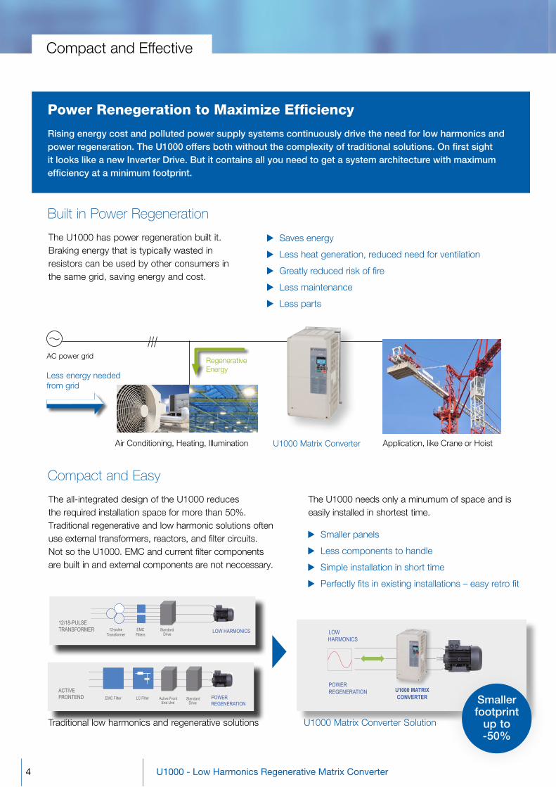
Power Renegeration to Maximize Efficiency
rising energy cost and polluted power supply systems continuously drive the need for low harmonics and power regeneration. The U1000 offers both without the complexity of traditional solutions. On first sight it looks like a new Inverter Drive. But it contains all you need to get a system architecture with maximum efficiency at a minimum footprint.
compact and effective
traditional low harmonics and regenerative solutions
the all-integrated design of the U1000 reduces the required installation space for more than 50%. traditional regenerative and low harmonic solutions often use external transformers, reactors, and filter circuits. not so the U1000. emc and current filter components are built in and external components are not neccessary.
Compact and Easy
LOW HARMONICS
U1000 MATRIXCONVERTER
TRY THE EFFICIENT WAY – U1000 MATRIX CONVERTER
U1000 – Makes it Easy
POWER REGENERATION
U1000 matrix converter solution
Smaller footprint
up to -50%
U1000 matrix converter
regenerative energy
air conditioning, Heating, illumination
ac power grid
Less energy needed from grid
application, like crane or Hoist
the U1000 has power regeneration built it. Braking energy that is typically wasted in resistors can be used by other consumers in the same grid, saving energy and cost.
Built in Power Regeneration
X saves energy
X Less heat generation, reduced need for ventilation
X greatly reduced risk of fire
X Less maintenance
X Less parts
the U1000 needs only a minumum of space and is easily installed in shortest time.
X smaller panels
X Less components to handle
X simple installation in short time
X Perfectly fits in existing installations – easy retro fit

AC Power grid Motor
Magnetic contactor
Not necessary!
U1000
Emergency Stop
AC Power grid Motor
U1000
Contactor
ContactorContactor
Not necessary!
X no trouble in it and control systems
X reliable operation
5U1000 - Low Harmonics Regenerative Matrix Converter
Features and Functions
Precise control of induction and permanent motors with or without encoder
Highly efficient ac to ac direct conversion
automatic motor data adjustment
Built in emc filter
13 language full text keypad built in
10 years maintenance free design
Built in Functional Safety
the U1000 comes with a built in dual-channel safe torque off (sto) function that meets the requirements of siL3/Ple and offers an easy way to improve machine safety without the need for complex external wiring.
Improved Power Factorthe U1000 provides a power factor close to one. By that it reduces losses in generators, transformers and cables, allowing a size down of these components for new installations or the possibility to add more drives to an existing installation without increasing transformer power.
Power factor:0.98
Clean Powerwith the YasKawa U1000 typical field problems caused by current harmonics, such as excessive heating of power grid devices or malfunction of peripheral electronics, are history. the U1000 matrix converter provides clean power with a total harmonic current distortion of less than 5%.
X no over-dimensioning of transformers, generators, or cables
X Less watt loss on power grid components
X sinusoidal input current with power factor ~0.98
X easy installation by all-integrated design
X reduced lifecycle cost
Standard AC Drive With U1000input current
X saves energy
X Less heat generation, reduced need for ventilation
X greatly reduced risk of fire
X Less maintenance
X Less parts
X simple wiring
X Less components and higher reliability
Built in Bypass Operation
the U1000 has a built in bypass function. whenever an application is running at the frequency and voltage of the power grid, U1000 can stop modulating the output and switch the motor directly to the grid.
X no external components needed
X minimum watt loss on drive
X silent motor operation
U1000 – A Class of its Own

6 U1000 - Low Harmonics Regenerative Matrix Converter
Engineering Tools for YASKAWA Inverter Drives
X all in one tool for parameter management, drive setup, monitoring, and fault diagnostics
X convenient Pc-based drive-setup, monitoring and diagnostic functions
X Built-in scope function
X online and offline parameter editing
economically optimized water skiing facility
X no additional i/os necessary
X no PLc required - reduced the system cost to less than 50% of the initial estimate
Benefits
X PLc or other external controllers not necessary
X easy to use
X constant scan cycle of 1 ms
X easy to learn graphical program-ming with online monitoring
X Higher reliability and less cost by lower number of compo-nents
Example projects
Efficient brake sequence
X Flexible sequence for mechanical brake of hoists
X avoids brake wear and unsafe operation
DriveWorksEZ for easy Installation and reliable Operation
DriveworkseZ® adds programmable functions that can tailor the U1000 matrix converters to the machine without the help of external controllers such as a PLc. this provides the user with easy access to the power of the inverters through an icon-based, graphical programming environment.
DriveWizard Plus for easy Engineering
manage the unique settings for all your drives right on your Pc. an indispensable tool for drive setup and maintenance. edit parameters, access all monitors, create customized operation sequences, and observe drive performance with the oscilloscope function.
software

Escalators
Elevators
Cranes, Hoists
Robots
X elevators and escalators
X cranes and hoists
X centrifugal separators
Motor Test Benches
Winder
X winders
X Presses
X eccentrics
/TCP
Communication Options
X rs-422/485 (memoBUs/modbus at 115.2 kbps) standard on all models
X option cards available for all major fieldbuses
II/III
applications
7U1000 - Low Harmonics Regenerative Matrix Converter
For a wide Range of Industries
The U1000 Matrix Converter Unit saves energy and thereby money by reusing braking energy and providing a clean power supply. The maximum effect can be realized in applications with large-inertia loads, 4-quadrant loads, long-term energy feedback and quick braking.

8 U1000 - Low Harmonics Regenerative Matrix Converter
code Designations
A0414CCIMR-
Rated output current [A]11 0011... ...
414 0414
4
Environmental SpecificationStandard A
A A
Voltage Class3-phase, 200-240 Vac 23-phase, 380-480 Vac 4
Enclosure TypeIP00 AIP20/ NEMA Type1 F
Reserved
Model Number Key for the U1000 Matrix Converter
U
Customized SpecificationsStandard model AEMC Noise Filter Built-in E
E
Matrix SeriesU1000 U
SpecificationsEuropean spec. C
400 V Class CIMR-UC4AooooAAA0011 10 11 8.7 9.6
4 to 10 kHz
400
0014 13 14 10 110021 19 21 13 140027 25 27 19 210034 31 34 25 270040 36 40 31 340052 47 52 36 400065 59 65 47 520077 70 77 59 650096 87 96 70 770124 113 124 87 960156 142 156 113 124
0180 164 180 142 156
0216 197 216 164 1800240 218 240 197 2160302 275 302 218 2400361 329 361 275 3020414 377 414 329 361
U10
00 M
odel
Input
Curre
nt [A
]Ra
ted O
utput
Curre
nt [A
]Inp
ut Cu
rrent
[A]
Rated
Outp
ut Cu
rrent
[A]ND HD
200 V Class CIMR-UC2AooooAAA0028 25 28 20 22
4 to 10 kHz
400
0042 38 42 25 280054 49 54 38 420068 62 68 49 540081 74 81 62 680104 95 104 74 810130 118 130 95 1040154 140 154 118 1300192 175 192 140 1540248 226 248 175 192
U10
00 M
odel
Input
Curre
nt [A
]Ra
ted O
utput
Curre
nt [A
]Inp
ut Cu
rrent
[A]
Rated
Outp
ut Cu
rrent
[A]
Carrie
r Freq
uenc
y Ma
x. Ou
tput F
req. [
Hz]ND HD
Carrie
r Freq
uenc
y Ma
x. Ou
tput F
req. [
Hz]

Options
Inpu
t /
O
utpu
tO
ther
s O
pera
ting
E
nvir
onm
ent
Pow
er R
atin
gs
Specifications
Ambient Temperature -10 to +50 °c (open chassis)
humidity 95% rH or less (non condensating)
Storage Temperature -20 to +60 °c (short-term temperature during transportation)
Altitude Up to 1000 meters (output derating required above 1000 m, max. 3000 m)
Shock 10 to 20 Hz: 9.8 m/s² ; 20 to 55 Hz: 5.9 m/s², (Uc2a0028 - Uc2a0081, Uc4a0011 - Uc4a0077) 2.0 m/s² (Uc2a0104 - Uc2a0248, Uc4a0096 - Uc4a0414)
Protective Design iP00 open type enclosure standard, iP20/nema type 1 Kit optional
Standards UL508c, iec/en 61800-3, iec/en 61800-5-1, iso/en 13849-1 cat.3 PLe, iec/en 61508 siL3
Input voltage/ range 200 to 240 vac 50/60 Hz (-15% to +10%), 380 to 480 vac 50/60 Hz (-15% to +10%)
rated Input Frequency 50/60 Hz ± 3%
Output Frequency range 0 - 400 Hz
Input Power Factor 0.98 min (for rated operation)
Overload Capability Heavy Duty: 150% for 1 min, normal Duty: 120% for 1 min
Spe
ed
Feed
back
9U1000 - Low Harmonics Regenerative Matrix Converter
Item Description Model Code
Analogue Monitor 2 channel analogue output option ao-a3 −10 to +10 vDc (res. 1/2048)
Digital Output 8 channel digital output option Do-a3 6 photo couplers (48 v, 50 ma or less), 2 relay contact outputs max 250 vac/30 vDc, 1 a
Analogue Input 3 channel analogue input option ai-a3 −10 to +10 vDc (20 kΩ, res. 1/8192), 4 to 20 ma (500 Ω, res. 1/6554)
Digital Input 1 channel digital input option Di-a3 16 bit binary, 2 digit BcD + sign signal + set signal, +24 v (isolated), 8 ma 2 relay contact outputs max 250 vac/30 vDc, 1 a
Communication canopen si-s3 Interface Unit cc-Link si-c3 Devicenet si-n3 ethercat si-es3 ethernet/iP si-en3 / si-enD3 mecHatroLinK-ii si-t3 mecHatroLinK-iii si-et3 modbus tcP/iP si-em3 PowerLinK si-eL3 ProFiBUs-DP si-P3 ProFinet si-eP3
Com
mun
icat
ion
USB Copy Unit UsB converter for Pc tool usage and copy unit JvoP-181 for easy parameter setup duplication and backup in one
IP65 Operator Provides a simple way of installing the LcD remote operator JvoP-v11001 Mounting Frame of the drive on a cabinet wall or door
DriveWizard Plus software used for parametrization
IP20/NEMA Kit Frame 1: EZZ022745A, Frame 2: EZZ022745B, Frame 3: EZZ022745C, Frame 4: EZZ022745D, Frame 5: EZZ022745E, Frame 6: EZZ022745F
options and specifications
Open Collector Type Phase a, B, and Z pulse (complementary type), max. 50 kHz Pg-B3
Line Driver Type Phase a, B, and Z pulse (differential pulse) (rs-422),
max. 300 kHz, pulse monitor output Pg-x3

10 U1000 - Low Harmonics Regenerative Matrix Converter
2.2 Mechanical Installation
IP00 Enclosure Drives
W14-d
HH1
H2
H4
WD1
t1
D
t2
Figure 2
t1
HH1
H2W
DD1
t2W1
H44-d
Figure 1
W1 4-d H4
H1 H
H2Max 15 W Max 15
t1D1
D
t2
Figure 3
common_TMonly
2.2 Mechanical Installation
IP00 Enclosure Drives
W14-d
HH1
H2
H4
WD1
t1
D
t2
Figure 2
t1
HH1
H2W
DD1
t2W1
H44-d
Figure 1
W1 4-d H4
H1 H
H2Max 15 W Max 15
t1D1
D
t2
Figure 3
common_TMonly
U1000 Matrix Converter 400 v
2.2 Mechanical Installation
IP00 Enclosure Drives
W14-d
HH1
H2
H4
WD1
t1
D
t2
Figure 2
t1
HH1
H2W
DD1
t2W1
H44-d
Figure 1
W1 4-d H4
H1 H
H2Max 15 W Max 15
t1D1
D
t2
Figure 3
common_TMonly Frame 1/2
Frame 4
Models with Open-Chassis IP00/IP20
U1000 Matrix Converter 200 vModel No Rated Output [A]
FrameDimensions [mm] Weight [kg] w.
built in EMC FilterWeight [kg] standard model
CIMR-UC2_oooo_AA Normal Duty Heavy Duty W H (IP00) H (IP20) D W1 H1 H2 H4 D1 d IP00 IP20 IP00 IP200028 28 22 1 250 480 524 360 205 463 6.5 40 100 7 21 22.5 20 21.50042 42 28
2 264 650 705 420 218 629 11.5 40 115.5 1033 35 32 34
0054 54 420068 68 54
36 38 35 370081 81 680104 104 81
3 264 816 885 450 218 795 11.5 40 124.5 10 63 65 60 620130 130 1040154 154 130
4 415 990 1107 403 250 966 11.0 40 165 12 115 118 110 1130192 192 1540248 248 192 5 490 1132 1320 450 360 1104 14.5 49 181 14 181 185 176 180
Frame 5/6Figure 4
W1W2 W2 6-d H
4H
1 HH
2
Max 15Max 15
t2
t1D1
D
common_TMonly
Model No Rated Output [A]Frame
Dimensions [mm] Weight [kg] w. built in EMC Filter
Weight [kg] standard model
CIMR-UC4_oooo_AA Normal Duty Heavy Duty W H (IP00) H (IP20) D W1 H1 H2 H4 D1 d IP00 IP20 IP00 IP200011 11 9.6
1 250 480 524 360 205 463 6.5 40 100 7 21 22.5 20 21.50014 14 110021 21 140027 27 210034 34 270040 40 34
2 264 650 705 420 218 629 11.5 40 115.5 1033 35 32 34
0052 52 400065 65 52
36 38 35 370077 77 650096 96 77
3 264 816 885 450 218 795 11.5 40 124.5 10 63 65 60 620124 124 960156 156 124
4 415 990 1107 403 250 966 11 40 165 12 115 118 110 1130180 180 1560216 216 180
5 490 1132 1320 450 360 1104 14.5 49 181 14 181 185 176 1800240 240 2160302 302 240
6 695 1132 1460 450 560 1102 14.5 65 178 14 267 278 259 2700361 361 3020414 414 361
Dimensions
Frame 3

Standard Connection Diagram
Figure 3.2
Figure 3.2 Drive Standard Connection Diagram (example: CIMR-UB2
+-
+-
+
-
+
+
MU/T1V/T2W/T
UVW3
Ground
+
-
+
+
S1
S2
S3
S4
S5
S6
S7
MP
DM
DM
RP
A1
A2
A3
0 VAC
RRSS
IG
Drive
p1 n1
2 kΩ
S8
SC
0 V
0 V
AC
FM
AMAC
E (G)
+24 V
+V
MA
M1M2
MBMC
Forward Run / Stop
Reverse Run / Stop
External fault
Fault reset
Multi-speed step 1
Multi-speed step 2
External Baseblock
Jog speed
Multi-function digital inputs
(default setting)
Sink / Source mode selection wire link(default: Sink)
CN5-C
CN5-B
CN5-A
Option card connectors
Pulse Train Input (max 32 kHz)
Shield ground terminal
Multi-function analog/ pulse
train inputs
Power supply +10.5 Vdc, max. 20 mA
Analog Input 1 (Frequency Reference Bias)-10 to +10 Vdc (20 kΩ)
Analog Input 2 (Frequency Reference Bias)-10 to +10 Vdc (20 kΩ)0 or 4 to 20 mA (250 Ω)
Analog Input 3 / PTC Input (Aux. frequency reference)-10 to +10 Vdc (20 kΩ)
−V Power supply, -10.5 Vdc, max. 20 mA
MEMOBUS/Modbus comm. RS-422/RS-485
max. 115.2 kbps
Termination resistor(120 Ω, 1/2 W)
DIP Switch S2
Fault relay output 250 Vac, max. 1 A30 Vdc, max 1 A(min. 5 Vdc, 10 mA)
Multi-function relay output (During Run)250 Vac, max. 1 A30 Vdc, max 1 A(min. 5 Vdc, 10 mA)
Multi-function pulse train output(Output frequency)0 to 32 kHz (2.2 kΩ)
Multi-function analog output 1(Output frequency)-10 to +10 Vdc (2mA) or 4 to 20 mA
Multi-function analog output 2(Output current)-10 to +10 Vdc (2mA) or 4 to 20 mA
EDM (Safety Electronic Device Monitor)
Main Circuit
Control Circuit
shielded line
twisted-pair shielded line
main circuit terminal
control circuit terminal
R/L1S/L2T/L3
Three-phase power supply200 to 400 V50/60 Hz
R/L1S/L2T/L3
MainSwitch
Motor
Shielded Cable
M3M4
Multi-function relay output (Zero Speed)250 Vac, max. 1 A30 Vdc, max 1 A(min. 5 Vdc, 10 mA)
M5M6
Multi-function relay output (Speed Agree 1)250 Vac, max. 1 A30 Vdc, max 1 A(min. 5 Vdc, 10 mA)
SP
SN
AMFM
V
I
V I DIP Switch S1A2 Volt/Curr. Sel
DIP Switch S4A3 Analog/PTC Input Sel
PTC
AI
Off On DIP Switch S2Term. Res. On/Off
Jumper S3H1, H2 Sink/Source Sel.
Jumper S5AM/FM Volt./Curr. Selection
Terminal board jumpers and switches
FM
AM
Slide Switch S6DM+,DM- N.C./N.O. Selection
N.C.
N.O.
+-
+-
ONOFF
EMC filterSwitch
FE
YEC_common
Y-Capacitor
11U1000 - Low Harmonics Regenerative Matrix Converter
connection Diagram

YASKAWA Europe GmbHDrives & Motion DivisionHauptstr. 18565760 EschbornGermany
+49 6196 [email protected]
Specifications are subject to change without noticefor ongoing product modifications and improvements.© YASKAWA Europe gmbh. All rights reserved.
Literature No. YEU_INV_U1000_EN_v1_0115Printed in Germany, January 2015