u. s. 1, 1971 design branch - irrigation toolboxirrigationtoolbox.com/technical notes/design...
TRANSCRIPT

U. S. Department of Agr icu l ture S o i l Conservation Serv ice Engineering Div is ion Design Branch
February 1, 1971
DESIGN NOTE NO. 12"
Subjec t : Control of Underground Corrosion
Buried metal p ipes and o the r mderground meta l o b j e c t s a r e sub jec t t o very rap id co r ros ion under c e ~ t a i n cond i t i ons , cond i t i ons which occur commonly enough t o demand c a r e f u l a t t e n t i o n . A cons iderable number of s t e e l i r r i g a t i o n p ipes and galvanized s t e e l p ipe sp i l lway condui t s i n s t a l l e d with SCS a s s i s t a n c e have f a i l e d by co r ros ion a f t e r only a few y e a r s ' s e rv i ce .
The purpose o f t h i s des ign no te i s t o provide i n t e r i m guidance i n ca r ry ing out t h e requirements of Engineering Standard 432-F and Engineering Memorandum-27 p e r t a i n i n g t o co r ros ion c o n t r o l . A t echn ica l r e l e a s e on t h e genera l t o p i c of underground co r ros ion w i l l be i ssued l a t e r i f i t proves t o be needed.
Engineering Standard 432-F a p p l i e s t o s t e e l i r r i g a t i o n p i p e l i n e s . Engineering Memorandum-27 covers t h e use of galvanized s t e e l and welded s t e e l p ipe i n e a r t h dams. The d i scuss ion t h a t fol lows i s d i r e c t e d toward these k inds of p ipe i n s t a l l a t i o n s . However, most o f i t i s equal ly app l i cab le t o any underground o r p a r t i y underground s t e e l s t r u c t u r e .
Aluminum a l l o y p ipes and s t r u c t u r e s a r e not s p e c i f i c a l l y included. They a r e s u b j e c t t o s i m i l a r co r ros ion processes , and t h e same p r i n c i p l e s apply t o t h e i r p ro t ec t ion , but t h e p r o p e r t i e s of aluminum d i f f e r from those of s t e e l i n s eve ra l important ways:
(1) A n a t u r a l ox ide forms inmediately upon exposure o f m y alt~rnin~im su r face t o t h e atmosphere, which provides s u b s t a n t i a l p r o t e c t i o n aga ins t co r ros ion i n most environments .
(2) The exc lus ion of oxygen from por t ions of t h e su r f ace , a s by chunks of s t i f f c l a y i n t h e b a c k f i l l around a p ipe , f o r example, promotes rap id cor ros ion a t p o i n t s where t h e oxide f i l m i s broken by prevent ing re-formation o f t h e n a t u r a l oxide.
( 3 ) Alkal ine s o i l s and waters a r e e s p e c i a l l y co r ros ive t o aluminum, while they tend t o i n h i b i t co r ros ion of s t e e l .
;?By A. S. Payne, Ass i s t an t Chief , Design Branch
( 4 ) The n a t u r a l p o t e n t i a l o f aluminum i s so c l o s e t o t h a t of z inc t h a t z inc anodes cannot be r e l i e d upon f o r ca thodic p ro t ec t ion . Magnesium anodes can be used, however.
(5) The co r ros ion of aluminum i s hastened r a t h e r than i n h i b i t e d by ca thodic p r o t e c t i o n i f t oo much cu r ren t i s appl ied .
NATURE OF CORROSION
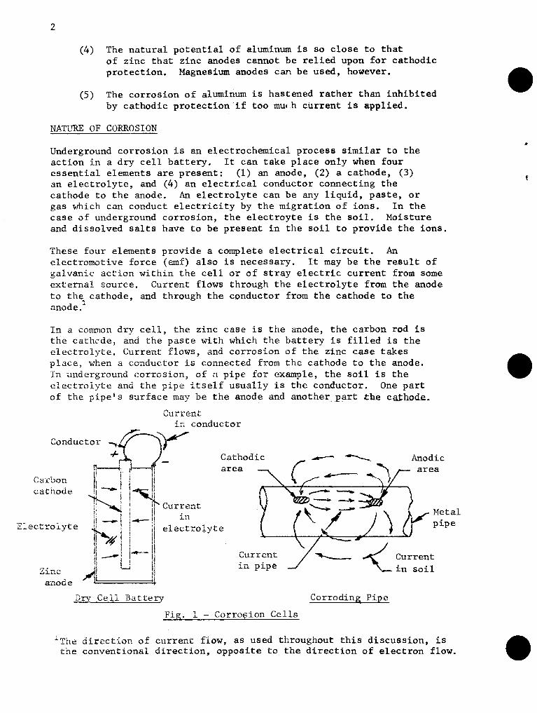
Underground co r ros ion i s an e lec t rochemica l process s i m i l a r t o t h e a c t i o n i n a d ry c e l l b a t t e r y . It can t a k e p l a c e only when four e s s e n t i a l elements a r e present : (1) an anode, (2) a cathode, (3) an e l e c t r o l y t e , and ( 4 ) an e l e c t r i c a l conductor connect ing t h e cathode t o t h e anode. An e l e c t r o l y t e can be any l i q u i d , p a s t e , o r gas which can conduct e l e c t r i c i t y by t h e migra t ion o f i ons . I n t h e c a s e o f underground cor ros ion , t h e e l e c t r o y t e i s t h e s o i l . Moisture and d isso lved s a l t s have t o be p re sen t i n t h e s o i l t o provide t h e ions .
These fou r elements provide a complete e l e c t r i c a l c i r c u i t . An e lec t romot ive f o r c e (emf) a l s o i s necessary. It may be t h e r e s u l t of galvariic a c t i o n w i t h i n t h e c e l l o r o f s t r a y e l e c t r i c c u r r e n t from some e x t e r n a l source. Current fiows through t h e e l e c t r o l y t e from t h e anode t o the-ca thode , and through t h e conductor from t h e cathode t o t h e an0de.l
In a common d ry c e l l , che z inc case i s t h e anode, t h e carbon rod i s t h e cathcde, and t h e p a s t e with which t h e b a t t e r y i s f i l l e d i s t h e e l e c t r o l y t e . Current flows, and co r ros ion of t h e z inc c a s e t akes p l ace , when a conductor i s connected from t h e cathode t o t h e anode. In underground cor ros ion , of n p ipe f o r example, t h e s o i l i s t h e e l e c t r o l y t e and t h e p i p c i t s e l f u sua l ly i s t h e conductor. One p a r t of t h e p i p e s s s u r f a c e may be t h e anode and a n o t h e r p a r t t h e c a h a d e .
Curren"~ Ir: conductor
Cathodic rCC- t. Anodic
7
Z ~ e c t r o k y t e
D r y C e i l Bat te ry Corroding Pipe
F i g . 1 - Corrogion C e l l s
he d i r e c t i o n of c u r r e n t flow, as used throughout t h i s d i scuss ion , i s t h e convent ional d i r e c t i o n , oppos i t e t o t h e d i r e c t i o n of e l e c t r o n flow.

The complete system (anode, cathode, e l e c t r o l y t e , and conductor) i s ca l l ed an e l e c t r o l y t i c o r galvanic c e l l o r corrosion c e l l . The anode and cathode may includc major areas of t h e pipe, o r they may be minute, as a t pinholes i n a p ro tec t ive coating. Rusting of i ron under a drop of water i l l u s t r a t e s t h e ac t ion of a complete corrosion c e l l within t h e drop. By d e f i n i t i o n , i n any e l e c t r o l y t i c c e l l , current flows from t h e anode t o t h e e l e c t r o l y t e and t o t h e cathode from the e l e c t r o l y t e . Corrosion takes place where current leaves t h e metal and en te r s t h e e l e c t r o l y t e , hence a t the anode.
CAUSES OF CORROSION
When the four e s s e n t i a l s of a corrosion c e l l (anode, cathode, e l e c t r o l y t e , and conductor) a r e present , as they usual ly a r e when a metal objec t i s buried i n t h e ground, t h e r a t e a t which corrosion takes p lace i n each c e l l depends upon t h e amount of e l e c t r i c current flowing, which i n t u r n depends upon t h e emf and the e l e c t r i c a l res is tance:
emf (vo l t s ) Current (amps) =
Resistance (ohms)
Thus, rapid corrosion i s promoted by a high emf and low c e l l res is tance . Since t h e e lec t ro ly te , which i s t h e s o i l , i s p a r t of t h e c e l l c i r c u i t , s o i l with a high res i s t ance r e t a r d s corrosion. Likewise, p ipe coatings having high e l e c t r i c a l r e s i s t ance i n h i b i t current flow from t h e metal t o t h e s o i l and so r e s i s t corrosion.
The condit ions t h a t can generate the emf necessary t o make a corrosion c e l l opera te a r e so numerous t h a t some of them a r e near ly always present . Following i s a p a r t i a l l i s t .
Proper t ies of t h e rcetal objec t i t s c l f Dissimilar metals connected together Flaws and inclusions i n t h e metal Forming s t r a i n s , and va r ia t ions i n i n t e r n a l s t r e s s New metal connected t o old metal Scratches, abrasions, pipe threads, e t c . , exposing clean metal M i l l s ca le
Propert ies of the s o i l o r o the r environment Variat ions i n s o i l moisture Variat ions i n aera t ion of t h e s o i l Varfations i n kind of s o i l Variat ions i n a c i d i t y o r o the r chemical proper t ies Par t of t h e metal submerged and pa r t exposed t o atmosphere Par t of t h e metal encased i n concrete and p a r t i n s o i l o r water
External influences Induced current from nearby e l e c t r i c a l equipment Stray currents i n t h e s o i l from grounded e l e c t r i c a l equipment
Probably t h e most general ly recognized of these i s t h e combination of d i s s imi la r metals. For example, it i s well known t h a t s t e e l w i l l corrode very rapidly when coupled t o brass o r copper i n a corros ive environment, i .e . , i n an e l e c t r o l y t e .
GALVANIC SERIES
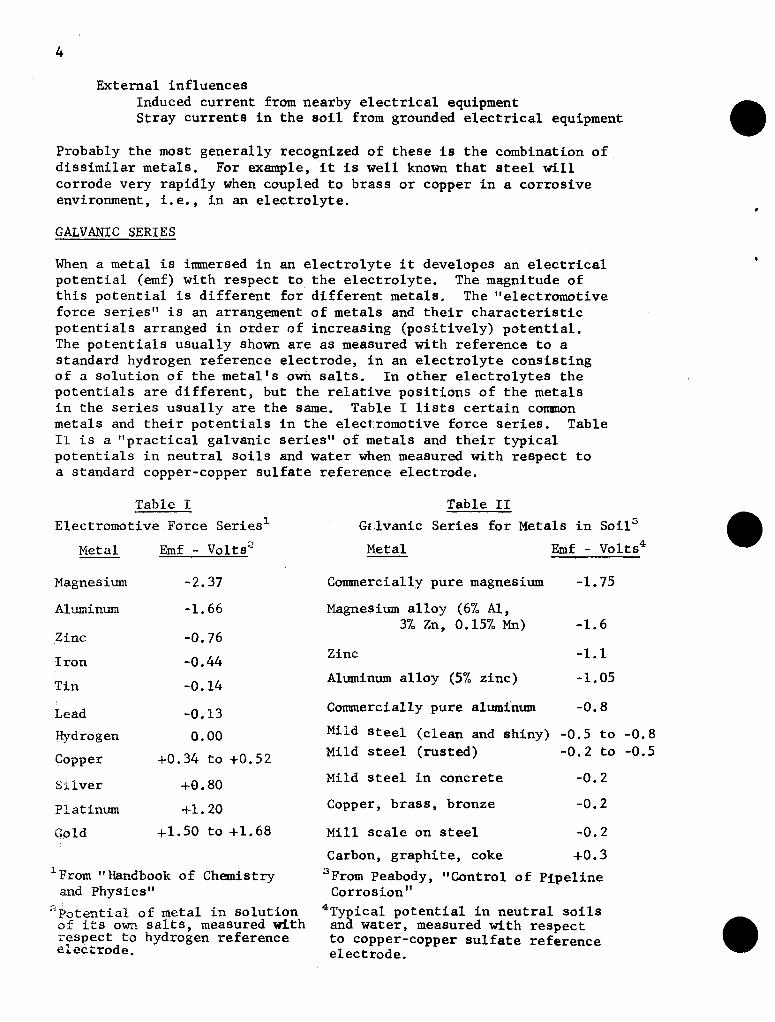
When a metal i s immersed i n an e l e c t r o l y t e i t developes an e l e c t r i c a l p o t e n t i a l (emf) with respect t o t h e e lec t ro ly te . The magnitude of t h i s p o t e n t i a l i s d i f f e r e n t f o r d i f f e r e n t metals. The "electromotive force se r i es" i s an arrangement of metals and t h e i r c h a r a c t e r i s t i c p o t e n t i a l s arranged i n order of increasing (posi t ive ly) po ten t i a l . The p o t e n t i a l s usual ly shown a r e a s measured with reference t o a standard hydrogen reference e lec t rode, i n an e l e c t r o l y t e consis t ing of a so lu t ion of t h e meta l ' s own s a l t s . I n o the r e l e c t r o l y t e s t h e p o t e n t i a l s a r e d i f f e r e n t , but t h e r e l a t i v e pos i t ions of t h e metals i n t h e s e r i e s usual ly a r e t h e same. Table I l i s t s c e r t a i n common metals and t h e i r p o t e n t i a l s i n t h e electromotive fo rce s e r i e s . Table I1 i s a " p r a c t i c a l galvanic se r i es" of metals and t h e i r typ ica l p o t e n t i a l s i n neu t ra l s o i l s and water when measured with respect t o a standard copper-copper s u l f a t e reference e lec t rode.
Table I Table I1
Electromotive Force ser ies1 Gz.lvanic Ser ies f o r Metals i n s o i l 3
Metal Emf - vol t s2 Metal Emf - vol t s4
Magnesium -2.37 Commercially pure magnesium -1.75
Aluminum -1.66
Zinc -0.76
Magnesium a l loy (6% A l , 3% Zn, 0.15% Mn) -1.6
-0.44 Zinc -1.1 I r o n
Tin -0.14 Aluminum a l loy (5% zinc) -1.05
Lead -0.13 Commercially pure aluminum -0.8
Hydrogen 0.00 Mild Steel (clean and shiny) -0.5 t o -0.8
Copper
S i lve r
Mild s t e e l (rusted)
Mild s t e e l i n concrete
Platinum +l. 20 Copper, brass , bronze -0.2
Gold +1.50 t o +1.68 M i l l s c a l e on s t e e l -0.2
Carbon, graphi te , coke +O. 3 'From "Handbook of Chemistry ~ r o m Peabody, "Control of Pipel ine
and Physics" corrosion "
a PatentiaT of metal i n so lu t ion 4 ~ y p i c a l p o t e n t i a l i n neu t ra l s o i l s of i t s ow. s a l t s , measured with and water, measured with respect respect t o hydrogen reference t o copper-copper s u l f a t e reference electrode. e lec t rode .

I n gene ra l , when any two meta ls a r e buried i n t h e ground, o r i m e r s e d i n any o t h e r e l e c t r o l y t e , and a r e connected e l e c t r i c a l l y (by an e l e c t r i c a l conductor) , a ga lvanic c e l l i s e s t ab l i shed i n which t h e meta l h igher i n t h e s e r i e s i s t h e anode and t h e meta l lower i n t h e s e r i e s i s t h e cathode.
PROTECTION AGAINST CORROSION
Coatings
Coatings which w i l l not conduct e l e c t r i c i t y o r t ransmi t mois ture a r e e f f e c t i v e i n l i m i t i n g underground cor ros ion . However, p r a c t i c a l l y a l l coa t ings have some minor flaws ("holidays") through which mois ture and e l e c t r i c c u r r e n t can pass . Corrosion tends t o concen t r a t e a t t h e flaws because they a r e t h e only p o i n t s a t which c u r r e n t can flow from t h e metal . A coated p i p e thus may be pe r fo ra t ed by co r ros ion i n l e s s t ime than an uncoated p ipe i n t h e same environment.
E l e c t r i c a l I n s u l a t i o n
Corrosion caused by d i s s i m i l a r meta ls can be prevented by e l e c t r i c a l l y i n s u l a t i n g one metal from t h e o t h e r ; f o r example, by us ing i n s u l a t i n g couplings t o connect copper p ipe and f i t t i n g s t o s t e e l pipe. I n s u l a t i o n a l s o may be app l i cab le i n c o n t r o l l i n g s t r a y cu r r en t cor ros ion .
Cathodic P ro t ec t ion
Cathodic p r o t e c t i o n of a buried p ipe c o n s i s t s of lowering t h e e l e c t r i c a l p o t e n t i a l o f t h e p ipe , r e l a t i v e t o t h e adjacent s o i l , t o t h e ex t en t char cu r r en t can flow only from t h e s o i l to t h e pipe. The whole p ipe becomes a cathode and does not corrode. A ca thodic p r o t e c t i o n i n s t a l - l a t l o n i s a cor ros ion c e l l i n which t h e p ipe i s t h e cathode and a s e p a r a t e , " s a c r a f i c i a l " anode i s provided. The anode usua l ly c o n s i s t s of a ba r , rod , o r wi re of metal o r carbon whose only func t ion i s t o be an anode. it i s expected t o corrode and, i f l e f t i n s e r v i c e long enough, t o be e s s e n t i a l l y consumed.
Cathodic p r o t e c t i o n i s provided e i t h e r by ga lvanic a c t i o n o r by impressed c u r r e n t . I n a ga lvan ic c e l l , d i s s i m i l a r meta ls a r e used f o r t h e anode ar,d cathode. When a s t e e l p ipe i s t o be p ro t ec t ed , t h e anode usua l ly i s z inc o r magnesium. I n an impressed cu r ren t c e l l , t h e emf i s suppl ied irom an o u t s i d e source of d.c . power o r , more o f t e n , c o m e r c i a l a.c. power passed through a r e c t i f i e r . The anode can be any e l e c t r i c a l conductor and usua l ly i s of a durable metal , such as a cor ros ion r e s i s t a n t c a s t i r o n , o r o f carbon.

Current in -tL connecting wire
zinc in soil
D. C. power source
Current in connecting
Steel pi
\-
1 Current d cast ire? - in soil
anode anode
(1) Galvanic (2) Impressed Current
Fig. 2 - Cathodic Protection TESTS FOR CORROSION CONTROL
Soil Resistivity
One of the most influential factors affecting the rate of corrosion and the design of cathodic protection is the resistivity of the soil. Resistivity is a unit measure of the electrical resistance of the soil. It is defined as the resistance of a unit cube, usually a one centimeter cube, to the passage of electric current and is expressed in resistance-length units, usually ohm-centimeter~ (ohm-cm). The resistance (R) of a given block of soil is equal to the resistivity (r) inultiplied by the length (1) in the direction of current flow, divided by the cross section area (a) perpendicular to the direction of current flow.
Soil resistivity has a major effect on the rate at which current passes from a metal surface into the soil, or from the soil into the metal, under a given emf and on the current a given anode can supply in a cathodic protection installation.
In general, resistivity decreases with increasing moisture in the soil and with increasing total salts. For practical purposes it is nearly constant for moisture contents from field capacity to saturation. The conductivity of a saturation extract of soil is used in Soil Survey measurements of total salts. This measure does not correlate well with resistivity, but does give some indication of the corrosivity of the soil. It has the advantage that it is available for many soils already tested.

p i t , can be measured wi th any of va r ious models of s ing le-probe instruments . These measure t h e r e s i s t a n c e between 2 e l ec t rodes i n a probe rod which i s i n s e r t e d i n t o t h e s o i l t o be t e s t e d . The equipment i s p o r t a b l e and t e s t s can be made quickly. The s o i l may not be a t t h e mois ture content it w i l l have a f t e r t h e p ipe i s i n s t a l l e d , however, i n which c a s e t h e readings w i l l not i n d i c a t e t h e r e s i s t i v i t y t o be expected when t h e p ipe i s i n s e rv i ce . A nea r ly - sa tu ra t ed cond i t i on f o r t h e t e s t can be achieved by boring a ho le t o t h e depth a t which t h e measurement i s t o be made, pouring water i n t o i t , and al lowing t h e water t o soak i n t o t h e s o i l be fo re making t h e t e s t .
S o i l r e s i s t i v i t y should be measured before a metal p i p e i s i n s t a l l e d and in'many cases a f t e r i t i s i n s t a l l e d , a l s o , e s p e c i a l l y i f t h e s o i l mois ture i s d i f f e r e n t a f t e r t h e p i p e i s i n s t a l l e d .
Laboratory Tes ts . The S o i l Mechanics Laboratory i n Lincoln, t h e Engineering Mate r i a l s Labora tor ies i n Por t land and For t Worth, and t h e S o i l Survey Labora tor ies i n Lincoln and Rivers ide a l l a r e equipped t o make r e s i s t i v i t y measurements. They use t h e Bureau o f S o i l s r e s i s t i v i t y cup o r s i m i l a r devices , Two o r t h r e e pounds o f s o i l should be s e n t t o t h e l abo ra to ry f o r each t e s t . A device s i m i l a r i n p r i n c i p l e t o t h e r e s i s t i v i t y cup but l a r g e r i s t h e " s o i l box." Its volume i s about 35 cubic inches , whi le t h a t o f B o f S cup i s 50 m l .
Since t h e r e s i s t i v i t y o f most s o i l s decreases wi th inc reas ing mois ture content , r e s i s t i v i t y t e s t s should be made wi th t h e samples a t a mois ture content r ep re sen t ine t h e w e t t e s t cond i t i on l i k e l y t o p r e v a i l f o r any s i g n i f i c a n t t ime i n t h e v i c i n i t y of t h e p i p e a f t e r i t i s i n s t a l l e d . For metal p ipes i n e a r t h dams, t h e s o i l should be t e s t e d i n a s a t u r a t e d condi t ion . The r e s i s t i v i t y a l s o i a a f f e c t e d by s a l t s i n t h e ground water. This should be considered i n t e s t i n g s o i l s which may become s a t u r a t e d wi th water having a h ighe r salt content than t h e n a t u r a l ground water.
F i e ld Tes ts : S ing le Probe. The r e s i s t i v i t y o f small volumes o f S o i l i n p l a c e a t o r near t h e su r f ace , o r i n a p ipe t r ench o r exp lo ra t ion
I n SCS experience t o d a t e , s ing le-probe r e s i s t i v i t y instruments have not given c o n s i s t e n t r e s u l t s . This probably i s because of t h e f r s e n s i t i v i t y t o l o c a l v a r i a t i o n s i n t h e s o i l . It i s l i k e l y t h a t t h e l o c a l r e s i s t i v i t y i s a l t e r e d somewhat by compression o f t h e s o i l when t h e probe i s i n s e r t e d .
F: i c ! 'Tests: Wcnner 4-Pin Method. The average r e s i s t i v i t y o f a - - - - -- - I n r ~ c . voiiL;..le of s o i l i n p l ace can b e measured quickly and e a s i l y , i t t h c equipment i s a v a i l a b l e , by t h e 4-pin method. Four e l ec t rodes arcb s tuck i n t o t h e ground equal ly spaced i n a s t r a i g h t l i n e . E l e c t r i c : ~ : r i c . ~ t i ; 'ippl i e d t o t h e end e l ec t rodes and t h e r e s u l t i n g change i n v o , t n ~ t i ~ ~ t w c e n the rwo i n r e m e d i a t e e l ec t rodes i s measured. From ;:~e mea;;,rcd current and vo l t age , t h e r e s i s t i v i t y can be ca l cu la t ed . The measurement i s considered t o r ep re sen t t h e s o i l i n t h e v i c i n i t y of clic p ins t o a depth equal t o t h e p i n spacing. Changes i n r e s i s t i v i t y wi th depth can be de tec ted by making a s e r i e s of measurements wi th t h e p i n s a t d i f f e r e n t spacings, e .g . , 5 , 10, 15, and 20 f e e t .

When r e s i s t i v i t y i s measured by t h i s method i n t h e v i c i n i t y of a p ipe l ine already i n place, t h e e lec t rodes a r e placed i n a l i n e t ransverse t o t h e p ipel ine . Otherwise, t h e p ipe would c a r r y p a r t of t h e e l e c t r i c current and t h e reading would not be cor rec t .
The 4-pin method i s commonly used i n r e s i s t i v i t y surveys f o r p ipel ines . It i s espec ia l ly adapted t o quickly surveying a l a r g e a r e a and determining i n general what corrosion p ro tec t ion w i l l be needed. The r e s u l t s a r e l imi ted , of course, t o r e s i s t i v i t y a t t h e moisture content p reva i l ing a t t h e t i m e of t h e survey.
Soi l pH
Acid s o i l s and waters genera l ly hasten t h e corrosion of steel, and a l k a l i n e s o i l s and waters tend t o i n h i b i t corrosion of s t e e l . Alkaline condit ions increaae t h e r a t e of corrosion of aluminum al loys . The pH of t h e s o i l and water t o which a metal p ipe w i l l be exposed should be t e s t e d before t h e p ipe i s i n s t a l l e d .
Laboratory Tests . The So i l Mechanics Laboratory, Engineering Mater ia ls Laboratories, and Soi l Survey Laboratories a l l can t e s t s o i l pH. Samples f o r pH t e s t s should be held a t t h e i r n a t u r a l moisture content during handling and shipping t o t h e labora tory because i r r e v e r s i b l e chemical changes t h a t a f f e c t t h e pH take p lace i n some s o i l s i f they a r e allowed t o dry.
Fie ld Tests . Por table "pH meters" a r e ava i l ab le by which s o i l pH can be measured e l e c t r i c a l l y . Some SCS s o i l survey personnel a r e equipped with such instruments.
Pipe-to-Soil Po ten t i a l
The t q p i p e - t o - ~ o i l p o t e n t i a l f 1 i s t h e p o t e n t i a l d i f fe rence between t h e pipe and a standard reference e lec t rode i n e l e c h r i c a l contact with t h e s o i l . A copper-copper s u l f a t e e lec t rode i s usual ly used as t h e reference e lec t rode. The e lec t rode i s placed i n t h e s o i l near t o t h e pipe, o f t e n d i r e c t l y over it, t o read t h e p o t e n t i a l r e l a t i v e t o "closet ' earth. The pipe- to-soi l p o t e n t i a l speci f ied i n Engineering Standard 432-F should be measured with t h e e lec t rode near t o t h e pipe. Some t e s t s r equ i re p o t e n t i a l s t o a "remoten e lec t rode 100 f e e t o r more-away from t h e pipe.
P ipe - to - so i l p o t e n t i a l s a r e read i n var ious ways, wlth and without applied current from an ou t s ide source, t o determine where p ipes a r e corroding, t o es t imate t h e r a t e of corrosion, t o es t imate t h e amount of current required f o r cathodic protec t ion, t o t e s t cathodic protec t ion a f t e r i t is i ~ s t a l l e d , to determine p ipe - to - so i l r e s i s t ance , and f o r var ious o the r purposes.
A copper-copper s u l f a t e e lec t rode and a h igh-res is tance voltmeter a r e necessary f o r the measurement of p ipe- to-soi l po ten t i a l s . Some of t h e t e s t s a l s o requi re equipment f o r applying an a l t e r n a t i n g o r in te r rup ted d i r e c t current t o t h e pipe and f o r measuring the current . Performance and cor rec t i n t e r p r e t a t i o n of these tests requ i re some t r a i n i n g and experience. A number of consult ing firms s p e c i a l i z e i n corrosion contro l survey and design work. It may be advisable t o cont rac t f o r t h e i r services i f SCS personnel with t h e necessary t r a i n i n g a r e not avai lable .
CATHODIC PROTECTION
Anodes
Zinc o r magnesium anodes genera l ly may be used f o r p ro tec t ion of s t e e l pipe. Zinc anodes usual ly a r e d e s i r a b l e i n s o i l of e spec ia l ly low r e s i s t i v i t y because of t h e i r longer l i f e . However, zinc anodes should not be used i n a l k a l i n e s o i l . Magnesium anodes should be used f o r galvanized pipe.
Required Pipe-to-Soil Po ten t i a l
The open-c i rcui t p o t e n t i a l of mild s t e e l i n neu t ra l s o i l , r e fe r red t o a copper-copper s u l f a t e e lec t rode , i s -0.2 t o -0.8 v o l t ( see page 4). That o f zinc (or a new galvanized pipe) i s -1.1 vo l t s . For complete cathodic p ro tec t ion of a pipe, t h e current from t h e anodes must be s u f f i c i e n t t o increase the d i f fe rence i n p o t e n t i a l between the p ipe and the adjacent s o i l t o more than the maximum open-circuit d i f ference .
The c r i t e r i o n i n Engineering Standard 432-F f o r cathodic p ro tec t ion o f s t e c i i r r i g a t i o n pipe i s t h a t t h e p ipe- to-soi l p o t e n t i a l , with p ro tec t ion i n s t a l l e d , must be not l e s s than 0.85 v o l t (negative) , r e fe r red t o a copper-cop9er s u l f a t e e lec t rode . To p ro tec t t h e zinc coating on a galvanized p i p e i n neutral. o r near ly n e u t r a l s o i l , a pipe- to-soi l p o t e n t i a l o f a t l e a s t 1.15 (negative) should be maintained.
T h e required c a t h o ~ i c p ro tec t ion current can be measured by applying t e s t current3 and measuring t h e p ipe- to-soi l p o t e n t i a l s o r can be estimated as described i n Engineering Standard 432-F. The values of C i n the formula f o r required current given i n Engineering Standard 432-F (C = 32 f o r Class A coatings and C = 60 f o r Class B coat ings) a r e conservative f o r d i e l e c t r i c coat ings i n good condition. However, coat ings which a r e not durable may l o s e t h e i r insu la t ing qua l i ty , and considerably higher cu r ren t may be reqaired than these values would indica te . The C value f o r bare p i p e would be something l i k e 1000. Fortunately, i n neu t ra l s o i l s the current requirement tends t o decrease with time, a f a c t o r tending t o counterbalance the e f f e c t of a moderate amount of d e t e r i o r a t i o n of t h e coating.
Zinc coating does not provide e l e c t r i c a l insu la t ion . Hence, t h e C value f o r a galvanized pipe without an add i t iona l , d i e l e c t r i c coat ing i s equivalent t o t h a t f o r bare pipe. For bituminous coated galvanized CMP, SCS engineers i n Nebraska use a C of 120.
Anode Current
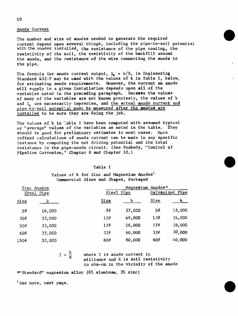
The number and s i z e of anodes needed t o generate t h e required current depend upon severa l th ings , including t h e p ipe- to-soi l po ten t i a l with the anodes i n s t a l l e d , t h e res i s t ance of t h e p ipe coating, t h e r e s i s t i v i t y of t h e s o i l , the r e s i s t i v i t y of t h e b a c k f i l l around t h e anode, and t h e res i s t ance of t h e wire connecting t h e anode t o t h e pipe.
The formula f o r anode current output, L, = k/R, i n Engineering Standard 432-F may be used with t h e values of k i n Table I, below, f o r est imating anode requirements. However, t h e current an anode w i l l supply i n a given i n s t a l l a t i o n depends upon a l l of t h e va r iab les noted i n t h e preceding paragraph. Becaase t h e values of many of t h e va r iab les a r e not known precise ly , t h e values of k and I, a r e necessa r i ly imprecise, and t h e ac tual anode current and p ipe - to - so i l potentLa1 must be measured a f t e r t h e anddes a r e i n s t a l l e d t o be su re they a r e doing t h e job.
The values of k i n "able I have been computed with assumed typ ica l o r "averagef1 values of t h e va r iab les as noted i n t h e table. They should be good f o r preliminary est imates i n most cases. More refined ca lcu la t ions of anode current can be made i n any s p e c i f i c ins tance by computing t h e net dr iv ing p o t e n t i a l and t h e t o t a l r e s i s t ance i n t h e pipe-anode c i r c u i t . (See Peabody, "Control of Pipel ine Corrosion," Chapter 8 and Chapter 10.)
Table I
Values of k for Zinc and Magnesium Anodes1 Commercial Sizes and Shapes, Packaged
Zinc Anodes S tee l Pk.pe
Size - k
Magnesium Anodes* S tee l Pipe Galvanized Pipe
Size - k Size k
I = - where I i s anode current i n mil l iwrps and R i s s o i l r e s i s t i v i t y i n ohm-cm i n t h e v i c i n i t y of the anode
*I Standard" magnesium a l l o y (6% aluminum, 3% zinc)
'see note, next page.

Note: Above k va lues a r e based on t h e fol lowing assumptions:
1. S t e e l p ipe : -0.85 v o l t p ipe - to - so i l p o t e n t i a l .
2. Galvanized p ipe : -1.15 v o l t p ipe - to - so i l p o t e n t i a l .
3. Class B p i p e coa t ing , C = 60 (Eng. Standard 432-F).
4. Surface a r e a of p i p e exposed t o s o i l - 1258. s q . f t .
5. Anodes a r e "packaged" o r bedded i n chemical b a c k f i l l ; e .g . , gypsum and bentoni te .
Higher k va lues a r e app l i cab le when t h e p ipe t o be p ro t ec t ed i s poorly i n s u l a t e d from t h e s o i l . For example, i f C i s 120 i n s t e a d of 60, o t h e r cond i t i ons being t h e same, t h e corresponding k i s 20 t o 40 percent h igher tha:i given i n t h e t a b l e . For ba re p ipe , anode k va lues a r e roughly twice those i n t h e t ab l e .
Anode L i f e
Magnesium anodes a r e consumed a t t h e r a t e of about 17 pounds pe r yea r p e r ampere de l ivered , ard z i n c anodes a t t h e r a t e of about 26 pounds pe r year pe r ampere. Since anodes can be expected t o s t o p func t ioning before they a r e completely consumed, a " u t i l i z a t i o n f s c t o r " of 0.75 t o 0.85 usua l ly i s appl ied i n c a l c u l a t i n g anode l i f e . The formulas f o r anode l i f e i n Engineering Standard 432-F inc lude a u t i l i z a t i o n f a c t o r o f 0.88.
Typical s i n g l e and n u l t i p l c anode i n s t a l l a t i o n s a r e i l l u s t r a t e d i n Figure 3 ; arid a d d i t i o n a l d e t a i l s of anode i n s t a l l a t i o n a r e given i n t h e Appendix, which i s a copy o f Montana job shee t ENG 301 e n t i t l e d " I n s t a l l a t i o n of Galvanic Anodes f o r Corrosion P ro tec t ion of Buried S t e e l P ipe l ines ."

Powder-weld Test station
connection Insulated wire
Single Anode Installation
Test station
Insulated connect ions Powder-weld Insulated eonneci;ion -coated
Anodes P i p e
for magnesium 10' m i n .
wire
Fig. 3 - Typical Anode InstalPations

The cu r ren t t h a t can flow from an anode depends l a r g e l y upon t h e r e s i s t i v i t y of t h e m a t e r i a l around i t . Therefore, i t i s important t h a t anodes be i n s t a l l e d where t h e s o i l i s moist and be b a c k f i l l e d wi th t h e lowest r e s i s t t v i t y m a t e r i a l ob ta inable . General ly , "packaged" anodes should be used, i n which t h e magnesium o r z inc ba r s a r e prepackaged i n a uniform chemical b a c k f i l l o f low r e s i s t i v i t y . Ear th b a c k f i l l should be f i rmly compacted around t h e packaged anode. I f packaged anodes a r e not a v a i l a b l e , ba re modes can be i n s t a l l e d i n d r i l l e d holes about 8 inches i n diameter and b a c k f i l l e d wi th a mix tu re& gypsum and b e n t o n i t e i n about equal propor t ions.
Anodes can be i n s t a l l e d v e r t i c a l l y o r ho r i zon ta l ly . This may be governed by s o i l s t r a t a , moisture condi t ions o r o t h e r f a c t o r s . 'hen two o r more anodes a r e used, they should be spaced a t l e a s t 10 f e e t a p a r t . Two o r more anodes connected t o a p ipe at one l o c a t i o n can be s t rung out i n a l i n e perpendicular o r p a r a l l e l t o t h e p ipe c e n t e r l i n e and connected t o a s i n g l e header wire . The i d e a i s t o o b t a i n uniform d i s t r i b u t i o n along t h e p i p e of t h e cu r r en t passing through t h e s o i l from t h e anodes. The c l o s e s t anodes should be not l e s s than about 5 f e e t from t h e pipe. This i s more c r i t i c a l f o r ~ a g n e s i u m than f o r z inc anodes.
Connection between t h e p ipe and t h e anodes should be made wi th i n s u l a t e d copper wire , #8 AWG o r l a r g e r . Copper w i re can be fas tened t o s t e e l o r galvanized p i p e by braz ing o r by t h e powder- weld ( thermi t ) p rocess . Pipe coa t ing damaged i n t h e process should be r epa i r ed , and exposed wi re and weld metal should be coated, Local cor ros ion of t h e p i p e ad jacent t o t h e copper w i re may t a k e p l ace i f t h e whole connection i s no t thoroughly coated t o exclude moisture. Wire s p l i c e s can be made wi th s p l i t - b o l t connectors o r by powder-welding o r brazing, and must be taped o r o therwise in su la t ed .
Bonding
Unless t h e p i p e j o i n t s a r e e l e c t r i c a l l y cont inuora, such a s welded j o i n t s , t h e p ipe s e c t i o n s and couplings i f any must be e l e c t r i c a l l y bonded toge the r t o permit cu r r en t t o flow from t h e anodes t o a l l p a r t s t o be p ro t ec t ed . I f metal an t i - s eep c o l l a r s a r e used, they a l s o should be bonded t o t h e pipe. Bonding may be' accomplished wi th V6 AWG i n s u l a t e d copper wire brazed o r powder-welded t o t h e p ipe , Stranded wire may be p r e f e r a b l e t o s o l i d w i re i f f l e x i b i l i t y i s needed. The i n s u l a t i o n should have a t l e a s t a 600-volt r a t i n g , and must be tough and waterproof . PVC and polye thylene i n s u l a t i o n designed f o r d i r e c t b u r i a l a r e s a t i s f a c t o r y . A s wi th o t h e r connect ions t o t h e p ipe ,

t h e connections should be coated and p ipe coa t ing damaged i n t h e process should be repa i red .
Tes t S t a t i o n s
Each anode i n s t a l l a t i o n , cons i s t i ng o f an anode o r group of anodes connected t o t h e p ipe a t a s i n g l e p o i n t , must be provided with a means of checking t h e anode c u r r e n t , t h e p i p e - t o - s o i l p o t e n t i a l , and t h e anode- to-so i l p o t e n t i a l .
A simple way o f doing t h i s i s t o br ing t h e wire from t h e anodes and t h e wire from t h e p ipe both i n t o a common junc t ion box above ground a t an a c c e s s i b l e l o c a t i o n nea r t h e pipe. This arrangement i s i l l u s t r a t e d i n F igure 4. I n opera t ion , t h e two wires a r e joined with a s p l i t - b o l t connector and taped. For t e s t i n g , t h e t a p e i s removed and t h e wlres a r e disconnected. The wires should be cleaned and fas tened toge the r s ecu re ly each tune they a r e reconnected and t h e whole s p l l c e should be thoroughly sea led wi th rubber o r p l a s t i c tape . O themise , a high r e s i s t a n c e can develop i n t h e connection as a r e s u l t o f co r ros ion o f t h e wires .
f Post - Weatherproof junc t ion box
Wire from p ipe
connection w a t e r t i g h t
Connector - t o be taped
Anode wire
Wire i n conduf t above ground
Fig. 4 - Test S t a t i o n D e t a i l
The ca thodic p r o t e c t i o n cu r r en t i s measured by connecting a m i l l i m e t e r between t h e wi re from t h e anodes and t h e wi re from t h e p ipe . P ipe - to - so i l p o t e n t i a l , wi th and without t h e anodes connected, i s measured by a t t ach ing t h e t e s t l ead from t h e copper-copper s u l f a t e e l e c t r o d e t o t h e wire from t h e p ipe , wi th and without t h e anode wire connected. Anode p o t e n t i a l i s measured by a t t ach ing t h e t e s t l ead t o t h e wi re from t h e anodes.
Figure 2 i n t h e Appendix shows a s l i g h t l y more e l a b o r a t e t e s t s t a t i o n us ing a switch and p lug- in receptacle. The anode-to-pipe c i r c u i t can be turned on o r o f f by t h e switch, and t h e t e s t equipment i s designed so t h a t i t can be simply plugged i n t o t h e r ecep tac l e f o r t e s t i n g .
Adjustment of Current
I f t h e anodes changethepipe- to-so i l p o t e n t i a l more than necessary f o r adequate p r o t e c t i o n , t h e anode cu r ren t can be l i m i t e d by i n s t a l l i n g a r e s i s t o r i n t h e c i r c u i t . It may be connected between t h e two wires i n t h e t e s t box descr ibed above. The o b j e c t i s t o extend t h e l i f e of t h e anodes. I f t h e anodes do n o t change t h e p i p e - t o - s o i l p o t e n t i a l enough, i t may be necessary t o add more anodes.
Maintenance
Cathodic p r o t e c t i o n i n s t a l l a t i o n s should be inspec ted and t e s t e d a t l e a s t on:e a year . S o i l mois ture and r e s i s t i v i t y change, e s p e c i a l l y where n a t u r a l condi t ions a r e a l t e r e d by a dam o r o t h e r s t r u c t u r e ; p i p e coa t ings d e t e r i o r a t e ; anode and cathode su r f aces change chemical ly; and o t h e r changes t a k e p l ace which can i n f luence t h e behavior of t h e ca thodic p r o t e c t i o n c i r c u i t . The p ipe should be inspec ted f o r s igns of cor ros ion , a l s o . Anodes should be replaced when they s top provid ing t h e necessary p ro t ec t ion .
INSTRUMENTS
Some of t h e instruments t h a t a r e a v a i l a b l e a r e descr ibed below with t h e i r approximate p r i c e s .
For s o i l r e s i s t i v i t y
So i l cup - Beckman Model CEL-M. Avai lable from Beckman, American Instrument , S o i l t e s t and o the r s . @ $65+_ (Used with conduct iv i ty br idge . )
Soil box - I?$' x 2%" x 9" plexiglass soil box available from M. C. Miller Co., 288 East Saddle River Road, Upper Saddle River, 8. J. @ $17t . (Used with Vibroground or similar combin;ition instrument, or with milliammeter and high resistance millivoltmeter or potentiometer.)
Conductivity bridge - Beckman Model RC-7. Portable, battery operated. Available from Beckman Instrument CO., Cedargrove, N. J.; American Instrument Co., 17 Pollock Avenue, Jersey City, N. J. @ $3555 . Conductivity bridge - Beckman Model RC-19. New light-weight, battery or line operated. Available from Beckman Instrument Co. @ $5955
Single-probe instrument - Available from Associated Research, Inc., 3758 West Belmont Avenue, Chicago; Agra Engineering Co. 4 551 South Quaker Avenue, Tulsa, Oklahoma, and others. @ $125- (Used with Vibroground or other bridge.)
Four-pin resistivity instrument - Vibroground Model 293. Battery operated, with steel case, 4 T-shaped ground probes, and test leads. Available from Associated Research, Inc., 3758 West Belmont Avenue, Chicago. @ $375$- .
For soil pH.
Pocket ?H meter - Beckman. Portable, battery operated, sturdy con'bination electrode. Available from Beclcman or any of their dealers: Chicago Apparatus Co., 1735 North Ashland Avenue, Chicago. @ $952
For p i p e - t o - s o i l potentiai, cathodic protection tests, etc.
Combination current and voltage meter. Available from M. C. Miller, Agra Engineering, and others. @ $225? . High resistance voltmeter or potentiometer. Available from M. C. Miller, Agra Engineering, and others. @ $80-2105 . Portable volt-ohm-milliammeter for pipe continuity checks. Available from Simpson Electric Co. or Triplett Electrical Instrument Co. @ $70? . Current interrupter. Available from M. C. Miller, Agra Engineering, and others. @ $165?
Copper-copper sulfate electrode. Available from M. C. Miller, Agra Engineering, and others. @ $15? .
REFERENCES
Peabody, A. W. "Control of Pipeline Corro sf-on, I' National Association of Corrosion Engineers, 192 pp., 1967.
Romanof f , M. "Underground Corrosion, I' National Bureau of Standards, 227 pp., 1957.
Engineering Standard 432-F. Irrigation Pipeline, Steel, SCS National Engineering Handbook, Section 2, 1969.
Engineering Memorandum-27, Earth Dams, Section E, Principal Spillways, 1969.


APPENDIX
INSTALLATION FOX CORROSION
OF GALVANIC ANODES PROrI'ECTIOM OF BURIED
STEEL PIPELINES The propcr i n s t a l l a t i o n of anodes i s the key t o t h e con t inu ing p ro t ec - t i o n fcom co r ros ion o f R bur i ed s t e e l p i p e l i n e . An improperly i n s t a l l e d and maintained anode can j n c r e a s e t h e r e s i s t i v i t y o f t h e s o i l surround- i n g i t and r e s u l t i n an underpro tec ted p i p c l i n e t l ~ o s dec reas ing t h e m a b l e l i f e o f the l i n e .
Anodes may ht? placed e i t h e r h o r i z o n t a l l y o r v e r t i c a l . l y i n r e l a t i o n to thc ~ i o t ' n d surface m d i n r e l a t i o n t o t h e p i p c l i n e e i t h e r p a r a l l e l o r pcrpenrlicul. ir , s e e FCgure 1. When plnccd h o r i z o n t a l l y , 1-hey s h a l l be r l t or b c l o u t.i:e bottoru e l e v a t i o n o f the p i p e l i n e . ITever p lnc? anodes I i l l n t r i l V e r t i c a l l y p laced anod~-+s s l ~ i l l h l v e a rn in i~~urr . J is - ~ 1 1 1 2 ~ of 3 i ~ c t betxcen the gzound s u r h c e and the t op of thc 'inode.
L o c ~ t i o n of the anodes i n r e l a t i o n t o t he p i p e l i n e i s no t c r i t i c a l c:,r:cp': i n the case of rna&ncsium 1d:ich nus t be p laced a m i n i m m d i s - t,:occ: of 10 f o c t f x c m t he p i p e l i n e .
1. I.:xcavatc itole o r t r e n c h for m o d s packa.ge.
: 3 . Pl.;,~ce ,I:-.c:.k pr;clc,?ge i n t he prep.,:rtd bed rca!ting s u r e that t h c imodc i s cr.nti?r:?d i n tlkc p z c k g c . Use e x t r c n ? c a u t i o n n o t t o get the a.nor!c p.:c!c:?za :;cC beEor-2 i t i s placed and 'oackLilled. :&?v?-r L i f t ----- t:i:: : : ~ t i i : t by the Lead wire .
APPENDIX 2
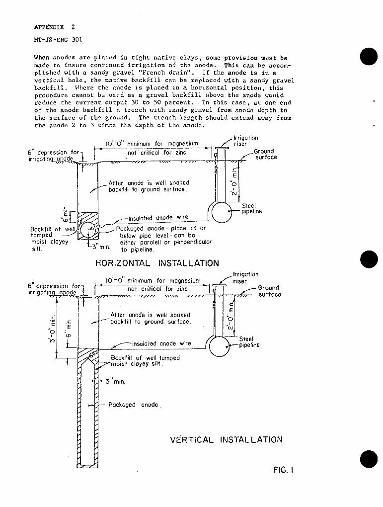
When anodes a r c p l aced i n t i g h t n a t i v e c l a y s , some p r o v i s i o n must be made t o i n s u r e continued i r r i g a t i o n o f t h e anode. Th i s can be accorn- p l i s h e d w i t h a sandy g r a v e l "French d ra in" . If t h e anode i s i n a v e r t i c n l h o l e , t h e nat ive backKi l l call be r cp l accd w i t h a sandy g r d v e l b a c k f i l l . Glherc t h c enode i s p laced i n a h o r i z o n t a l p o s i t i o u , t h i s procedure cannot be uscd as a g r a v e l backfi.11 above the anode would reduce t h e c u r r e n t o u t p u t 30 t o 50 p e r c e n t . In t h i s c a s e , a t one end o f t h e anode b a c k f i l l n t r e n c h w i t h s s x i y g r a v e l from anode dep th t o the s u r c a c e o f t h ? ground. The t r e n c h l e n g t h should ex tend away froin t h e anoze 2 t o 3 tirccs t h e & p t h of ~ h c anodc.
-- After anode is ~ ~ e l l soaked backfill to ground surfoce.
node - place a t or
HORIZONTAL Iil lSTALLATlON
After anode is well soaked backfill to ground surface.
VERTICAL INSTALLATION
FIG. I

C T or q u c l . 3
Bracket
weather p r o o f boy, with p lak and snap corers
STAT ION
in Sox
L
.- 111 [L
i I 90° connector - -
, y o -
for 7 k n o c ~ o u t I u _ I / \ Anode wire I o ) I"
C 7 flexi bie steel condl~it OUTLET & SWITCH
Anode wire FROh7 VIEW Anode wire
IRRIGATION RISER WITH ANODE TEST BOX
OUTLET BOX SIDE VIEW
--I C\L -
Note: Wire connections t o be silver so!dered .


