typical configurations in water and sewage technology
TRANSCRIPT

Applications & Tools
Answers for industry.
lCover
Typical Configurations in Water and Sewage Technology
SIMATIC PCS 7
Application Description May 2013

2 Typical Configurations in Water and Sewage Technology
V 1.0, Entry ID: 61024766
Cop
yrig
ht ©
Sie
men
s A
G 2
013
All
right
s re
serv
ed
Siemens Industry Online Support This entry is taken from the Siemens Industry Online Support. The following link takes you directly to the download page of this document: http://support.automation.siemens.com/WW/view/en/61024766 Caution: The functions and solutions described in this entry are mainly limited to the realization of the automation task. In addition, please note that suitable security measures in compliance with the applicable Industrial Security standards must be taken, if your system is interconnected with other parts of the plant, the company’s network or the Internet. For more information, please refer to Entry ID 50203404. http://support.automation.siemens.com/WW/view/en/50203404. You can also actively use our Technical Forum from the Service & Support Portal regarding this subject. Share your questions, suggestions or problems and discuss them with our strong forum community: http://www.siemens.com/forum-applications

Typical Configurations in Water and Sewage Technology V 1.0, Entry ID: 61024766 3
Cop
yrig
ht ©
Sie
men
s A
G 2
013
All
right
s re
serv
ed
s
SIMATIC PCS 7 Typical Configurations in Water and Sewage Technology Application Description
Configurations of a Small Sewage Treatment Plant
1 Configurations for Pump Control
2 Configuration of a Hydrostatic Level Measurement in a Steel Container
3
Configuration of the Hach-Lange SC1000 Process Computer
4
Links & Literature 5
History 6

Warranty and Liability
4 Typical Configurations in Water and Sewage Technology
V 1.0, Entry ID: 61024766
Cop
yrig
ht ©
Sie
men
s A
G 2
013
All
right
s re
serv
ed
Warranty and Liability
Note The Application Examples are not binding and do not claim to be complete regarding the circuits shown, equipping and any eventuality. The application examples do not represent customer-specific solutions. You are responsible for ensuring that the described products are used correctly. These application examples do not relieve you of your responsibility to use sound practices in application, installation, operation and maintenance. When using these application examples, you recognize that we will not be liable for any damage/claims beyond the liability clause described. We reserve the right to make changes to these application examples at any time and without prior notice. If there are any deviations between the recommendations provided in this application example and other Siemens publications – e.g. catalogs – the contents of the other documents have priority.
We do not accept any liability for the information contained in this document. Any claims against us – based on whatever legal reason – resulting from the use of the examples, information, programs, engineering and performance data etc., described in this Application Example shall be excluded. Such an exclusion shall not apply in the case of mandatory liability, e.g. under the German Product Liability Act (“Produkthaftungsgesetz”), in case of intent, gross negligence, or injury of life, body or health, guarantee for the quality of a product, fraudulent concealment of a deficiency or breach of a condition which goes to the root of the contract (“wesentliche Vertragspflichten”). The damages for a breach of a substantial contractual obligation are, however, limited to the foreseeable damage, typical for the type of contract, except in the event of intent or gross negligence or injury to life, body or health. The above provisions do not imply a change in the burden of proof to your disadvantage.

Preface
Typical Configurations in Water and Sewage Technology V 1.0, Entry ID: 61024766 5
Cop
yrig
ht ©
Sie
men
s A
G 2
013
All
right
s re
serv
ed
Preface Objective of this application
This document describes architectures and components of water and sewage treatment technology in its general setup. The hardware configurations in the examples are used for illustration purposes and may differ in real projects. Apart from displaying automation and communication concepts, process tags and drive connections within small plants will also be shown. As a rule, the designs were made in such a way as to guarantee high availability of the plant.
Main topics of this application The following core points are discussed in this application: • various concepts with plant configurations • required devices • required engineering tools
Valid until Valid from SIMATIC PCS 7 V8.0

1 Configurations of a Small Sewage Treatment Plant
6 Typical Configurations in Water and Sewage Technology
V 1.0, Entry ID: 61024766
Cop
yrig
ht ©
Sie
men
s A
G 2
013
All
right
s re
serv
ed
Table of Contents
Caution:......................................................................................................................... 2 Warranty and Liability ................................................................................................. 4 Preface .......................................................................................................................... 5 Table of Contents......................................................................................................... 6 1 Configurations of a Small Sewage Treatment Plant ...................................... 7
1.1 Sewage treatment plant overview........................................................ 7 1.2 Requirements ....................................................................................... 8 1.3 Automation concept.............................................................................. 8 1.3.1 Overview of concept 1.......................................................................... 9 1.3.2 Overview of concept 2........................................................................ 11 1.3.3 Overview of concept 3........................................................................ 13 1.4 Hardware and software components used......................................... 15
2 Configurations for Pump Control .................................................................. 16 2.1 Control methods for pump applications.............................................. 16 2.1.1 Direct starter – continuous runner...................................................... 17 2.1.2 Frequency-controlled pump – pressure control ................................. 19 2.1.3 Soft starter – continuous runner......................................................... 21 2.1.4 Y-∆ starter – continuous runner ......................................................... 23
3 Configuration of a Hydrostatic Level Measurement in a Steel Container .......................................................................................................... 25 3.1 Hydrostatic level display..................................................................... 25 3.2 Structure of the level display .............................................................. 26
4 Configuration of the Hach-Lange SC1000 Process Computer ................... 28 4.1 Process computer in the SIMATIC PCS 7 control system................. 28 4.2 Configuration of the control system with the process computer ........ 29
5 Links & Literature ............................................................................................ 30 6 History............................................................................................................... 30
1 Configurations of a Small Sewage Treatment Plant
Typical Configurations in Water and Sewage Technology V 1.0, Entry ID: 61024766 7
Cop
yrig
ht ©
Sie
men
s A
G 2
013
All
right
s re
serv
ed
1 Configurations of a Small Sewage Treatment Plant
1.1 Sewage treatment plant overview
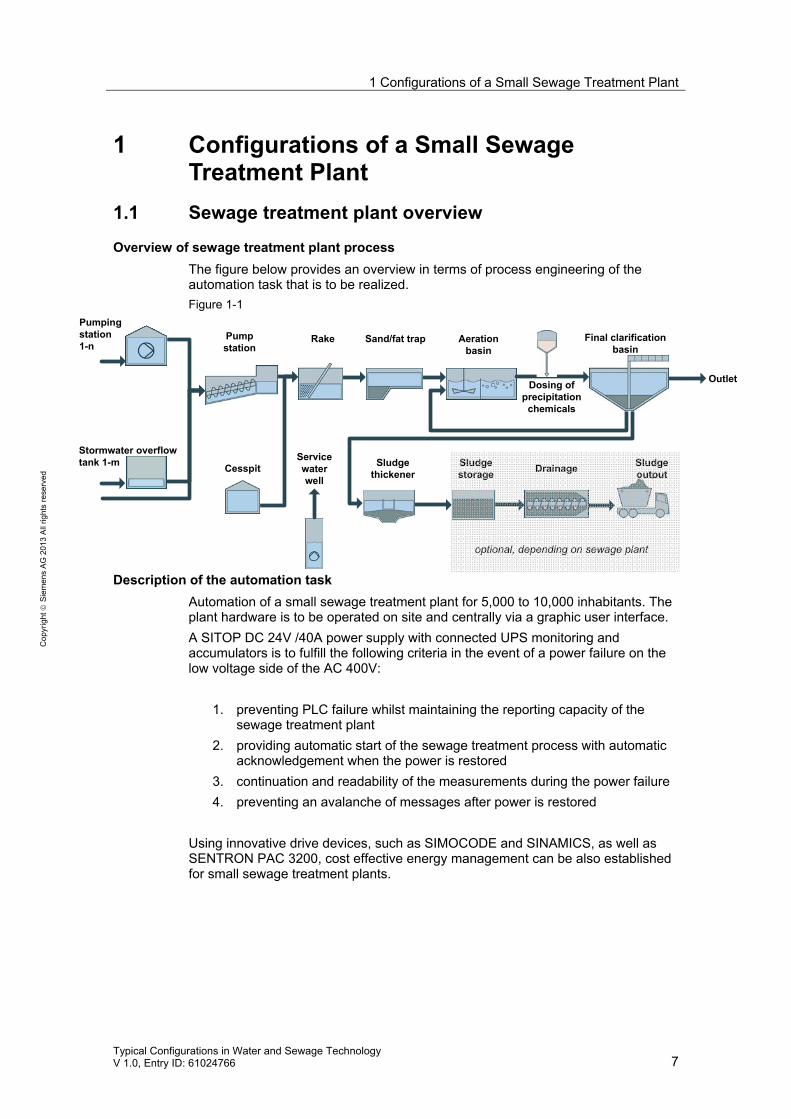
Overview of sewage treatment plant process The figure below provides an overview in terms of process engineering of the automation task that is to be realized. Figure 1-1
optional, depending on sewage plant
Description of the automation task Automation of a small sewage treatment plant for 5,000 to 10,000 inhabitants. The plant hardware is to be operated on site and centrally via a graphic user interface. A SITOP DC 24V /40A power supply with connected UPS monitoring and accumulators is to fulfill the following criteria in the event of a power failure on the low voltage side of the AC 400V:
1. preventing PLC failure whilst maintaining the reporting capacity of the sewage treatment plant
2. providing automatic start of the sewage treatment process with automatic acknowledgement when the power is restored
3. continuation and readability of the measurements during the power failure 4. preventing an avalanche of messages after power is restored
Using innovative drive devices, such as SIMOCODE and SINAMICS, as well as SENTRON PAC 3200, cost effective energy management can be also established for small sewage treatment plants.
Cesspit Sludgeoutput
Outlet
Pumping station 1-n
Stormwater overflow tank 1-m
Rake Sand/fat trap Aeration basin
Final clarification basin
Sludgethickener
Sludgestorage Drainage
Pump station
Dosing of precipitation
chemicals
Service water well

1 Configurations of a Small Sewage Treatment Plant
8 Typical Configurations in Water and Sewage Technology
V 1.0, Entry ID: 61024766
Cop
yrig
ht ©
Sie
men
s A
G 2
013
All
right
s re
serv
ed
1.2 Requirements
Requirements to the automation task Table 1-1
Requirement Explanation
All drives are to be equipped with on-site mode.
The operation is to be possible even if the controller fails.
The operating state is to be signaled on the control cabinet (operation/fault).
The display is either by “display” or light indicator.
Drives from 5.5 kW (without frequency converter) have to be equipped with a Υ/∆ combination.
Central operation at a central location via keyboard/mouse or touch screen.
On-site control station
Connection to central process control Archiving and logging is performed at the central process control. For variant 3 this can also be performed locally (logging with additional software).
All measurements should still be readable locally (24V DC power supply), even if the PLC fails or the 230V / 400V AC power supply.
All measurements and the controller have to be fed through the UPS buffered 24V DC supply.
1.3 Automation concept
Three possible automation concepts are described below.
• Variant 1 (p. 9 ) consists of 3 SIMATIC controllers. All aggregates and
measurements are connected to the controller via conventional input and output modules.
• Variant 2 (p. 10 ) consists of a soft PLC (WinAC). All aggregates and measurements are, if possible, connected via Profibus DP to the controller.
• Variant 3 (p. 12 ) is executed as a complete PCS 7 solution. The major part of the aggregates is connected with the central S7-400 via PROFINET. The measurements of devices that are not PROFINET-capable are connected via conventional I/O modules (4..20 mA).

1 Configurations of a Small Sewage Treatment Plant
Typical Configurations in Water and Sewage Technology V 1.0, Entry ID: 61024766 9
Cop
yrig
ht ©
Sie
men
s A
G 2
013
All
right
s re
serv
ed
1.3.1 Overview of concept 1
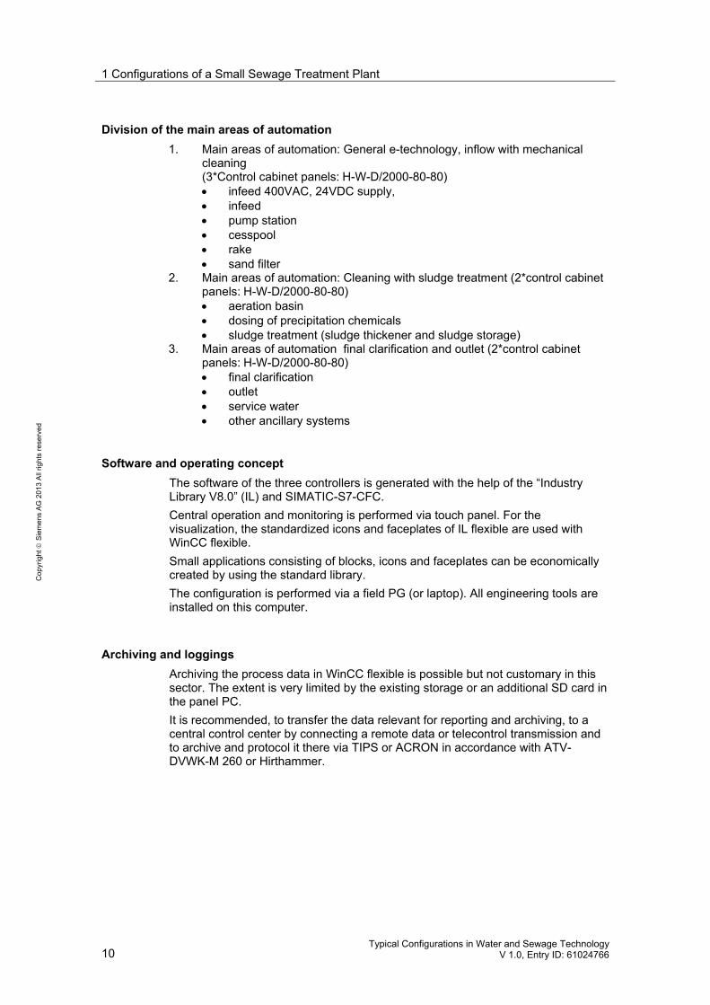
Schematic diagram The following figure displays the most important components of the concept:
Figure 1-2
Structure of concept 1 Concept 1 describes an automation concept with three controllers and a touch panel as central operating and monitoring station on the basis of WinCC flexible. All aggregates and measurements are connected with the controllers via I/O modules. The plant is divided into 3 main areas of automation (p. 10). Each main area of automation is provided with a controller. The plant status is displayed with LED light indicators. On-site operation is performed via knob switches in the control cabinet doors. The controller (IM 151-8) and the touch panel (IPC 277D) are provided with 24V DC via a buffered UPS.
1 Configurations of a Small Sewage Treatment Plant
10 Typical Configurations in Water and Sewage Technology
V 1.0, Entry ID: 61024766
Cop
yrig
ht ©
Sie
men
s A
G 2
013
All
right
s re
serv
ed
Division of the main areas of automation 1. Main areas of automation: General e-technology, inflow with mechanical
cleaning (3*Control cabinet panels: H-W-D/2000-80-80) • infeed 400VAC, 24VDC supply, • infeed • pump station • cesspool • rake • sand filter
2. Main areas of automation: Cleaning with sludge treatment (2*control cabinet panels: H-W-D/2000-80-80) • aeration basin • dosing of precipitation chemicals • sludge treatment (sludge thickener and sludge storage)
3. Main areas of automation final clarification and outlet (2*control cabinet panels: H-W-D/2000-80-80) • final clarification • outlet • service water • other ancillary systems
Software and operating concept The software of the three controllers is generated with the help of the “Industry Library V8.0” (IL) and SIMATIC-S7-CFC. Central operation and monitoring is performed via touch panel. For the visualization, the standardized icons and faceplates of IL flexible are used with WinCC flexible. Small applications consisting of blocks, icons and faceplates can be economically created by using the standard library. The configuration is performed via a field PG (or laptop). All engineering tools are installed on this computer.
Archiving and loggings Archiving the process data in WinCC flexible is possible but not customary in this sector. The extent is very limited by the existing storage or an additional SD card in the panel PC. It is recommended, to transfer the data relevant for reporting and archiving, to a central control center by connecting a remote data or telecontrol transmission and to archive and protocol it there via TIPS or ACRON in accordance with ATV-DVWK-M 260 or Hirthammer.

1 Configurations of a Small Sewage Treatment Plant
Typical Configurations in Water and Sewage Technology V 1.0, Entry ID: 61024766 11
Cop
yrig
ht ©
Sie
men
s A
G 2
013
All
right
s re
serv
ed
1.3.2 Overview of concept 2
Schematic diagram The following figure displays the most important components of the concept:
Figure 1-3
Structure of concept 2 Concept 2 describes an automation concept with a central controller (SIMATIC Soft PLC). The Soft PLC performs the PLC control tasks and at the same time it is used for central operation and monitoring via the touch panel on the basis of WinCC flexible. All aggregates and measurements are connected to the controller via Profibus DP. The optic PROFIBUS ring connects the meters in the panel with the Profibus nodes installed in the control cabinet. The SINAMICS and SIMOCODE drives have been connected to a linear structure in copper. The connection of this linear structure to the optic Profibus ring is via OLM. The availability of the PROFIBUS communication of the drives can be increased by swapping the copper cables for fiber optic cables. However, for this purpose additional OLM devices have to be provided for this kind of solution. On-site operation is via operating devices (OP) of the Profibus devices by SINAMICS and SIMOCODE. Devices without their own Profibus interface are operated/displayed via know switches and LED light indicators in the control cabinet doors.
1 Configurations of a Small Sewage Treatment Plant
12 Typical Configurations in Water and Sewage Technology
V 1.0, Entry ID: 61024766
Cop
yrig
ht ©
Sie
men
s A
G 2
013
All
right
s re
serv
ed
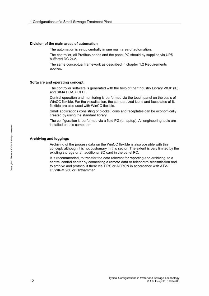
Division of the main areas of automation The automation is setup centrally in one main area of automation. The controller, all Profibus nodes and the panel PC should by supplied via UPS buffered DC 24V. The same conceptual framework as described in chapter 1.2 Requirements applies.
Software and operating concept The controller software is generated with the help of the “Industry Library V8.0” (IL) and SIMATIC-S7 CFC. Central operation and monitoring is performed via the touch panel on the basis of WinCC flexible. For the visualization, the standardized icons and faceplates of IL flexible are also used with WinCC flexible. Small applications consisting of blocks, icons and faceplates can be economically created by using the standard library. The configuration is performed via a field PG (or laptop). All engineering tools are installed on this computer.
Archiving and loggings Archiving of the process data on the WinCC flexible is also possible with this concept, although it is not customary in this sector. The extent is very limited by the existing storage or an additional SD card in the panel PC. It is recommended, to transfer the data relevant for reporting and archiving, to a central control center by connecting a remote data or telecontrol transmission and to archive and protocol it there via TIPS or ACRON in accordance with ATV-DVWK-M 260 or Hirthammer.

1 Configurations of a Small Sewage Treatment Plant
Typical Configurations in Water and Sewage Technology V 1.0, Entry ID: 61024766 13
Cop
yrig
ht ©
Sie
men
s A
G 2
013
All
right
s re
serv
ed
1.3.3 Overview of concept 3
Schematic diagram The following figure displays the most important components of the concept:
Figure 1-4
Structure of concept 3 Concept 3 describes a PCS 7 automation concept with a central controller (SIMATIC-S7-400) and a separate PC workstation that can be used for operating and monitoring as well as for engineering. All aggregates in this solution should be connected with the controller via PROFINET. The “copper” ring connects the PROFINET nodes, installed in the control cabinet, via a switch (X204-IRT) which provides a highly-available communication variant as redundancy manager. If a PROFINET node fails in the ring structure, the switch switches the available drive nodes to a linear structure within 30 ms, without any data getting lost. On-site operation is via operating devices (OP) of the PROFINET devices by SINAMICS and SIMOCODE. Devices without their own PROFINET interface are operated/displayed via know switches and LED light indicators in the control cabinet doors.
1 Configurations of a Small Sewage Treatment Plant
14 Typical Configurations in Water and Sewage Technology
V 1.0, Entry ID: 61024766
Cop
yrig
ht ©
Sie
men
s A
G 2
013
All
right
s re
serv
ed
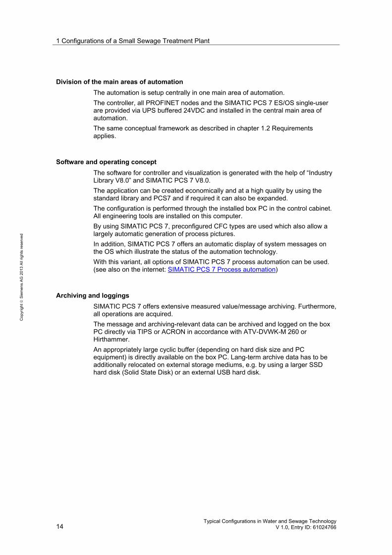
Division of the main areas of automation The automation is setup centrally in one main area of automation. The controller, all PROFINET nodes and the SIMATIC PCS 7 ES/OS single-user are provided via UPS buffered 24VDC and installed in the central main area of automation. The same conceptual framework as described in chapter 1.2 Requirements applies.
Software and operating concept The software for controller and visualization is generated with the help of “Industry Library V8.0” and SIMATIC PCS 7 V8.0. The application can be created economically and at a high quality by using the standard library and PCS7 and if required it can also be expanded. The configuration is performed through the installed box PC in the control cabinet. All engineering tools are installed on this computer. By using SIMATIC PCS 7, preconfigured CFC types are used which also allow a largely automatic generation of process pictures. In addition, SIMATIC PCS 7 offers an automatic display of system messages on the OS which illustrate the status of the automation technology. With this variant, all options of SIMATIC PCS 7 process automation can be used. (see also on the internet: SIMATIC PCS 7 Process automation)
Archiving and loggings SIMATIC PCS 7 offers extensive measured value/message archiving. Furthermore, all operations are acquired. The message and archiving-relevant data can be archived and logged on the box PC directly via TIPS or ACRON in accordance with ATV-DVWK-M 260 or Hirthammer. An appropriately large cyclic buffer (depending on hard disk size and PC equipment) is directly available on the box PC. Lang-term archive data has to be additionally relocated on external storage mediums, e.g. by using a larger SSD hard disk (Solid State Disk) or an external USB hard disk.

1 Configurations of a Small Sewage Treatment Plant
Typical Configurations in Water and Sewage Technology V 1.0, Entry ID: 61024766 15
Cop
yrig
ht ©
Sie
men
s A
G 2
013
All
right
s re
serv
ed
1.4 Hardware and software components used
The following configuration tools can be used: • Configuration SIMATIC SIMATIC Selection Tool • Configuration SIMATIC HMI SIMATIC HMI Selection Aid • Configuration Field PG SIMATIC Field PG M • Configuration Box PC SIMATIC BOX PC • Configuration motor branch circuit Motor Branch Circuit Configurator • Configuration switch, button, light indicator Control element • Configuration controls Industrial Controls • Process instruments PIA Life Cycle Portal

2 Configurations for Pump Control
16 Typical Configurations in Water and Sewage Technology
V 1.0, Entry ID: 61024766
Cop
yrig
ht ©
Sie
men
s A
G 2
013
All
right
s re
serv
ed
2 Configurations for Pump Control 2.1 Control methods for pump applications
Control and operation of a pump can be realized through various options.
Control types • supply of the pump via “SINAMICS G120” frequency converter • direct start of the pump via “SENTRON” circuit breaker • start with “SIRIUS 3RW44” soft starter • Y-∆ start through “SIMOCODE proV”
Note For detailed information on the connection of drives from the SINAMICS and MICROMASTER 4 family, please refer to the following entry:
http://support.automation.siemens.com/WW/view/en/58007228

2 Configurations for Pump Control
Typical Configurations in Water and Sewage Technology V 1.0, Entry ID: 61024766 17
Cop
yrig
ht ©
Sie
men
s A
G 2
013
All
right
s re
serv
ed
2.1.1 Direct starter – continuous runner
Schematic diagram Figure 2-1: Direct starter
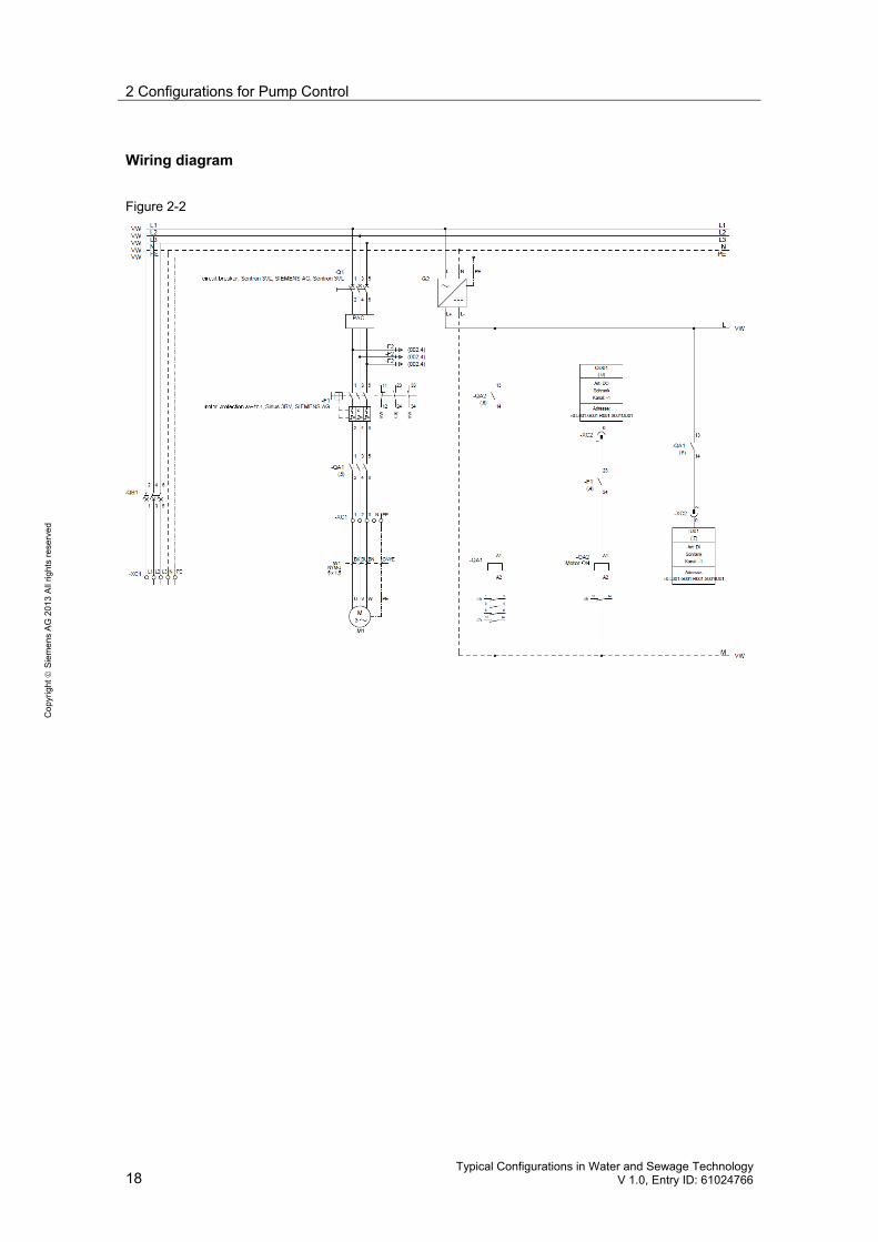
Requirement for the automation task Table 2-1
Requirement Explanation (see wiring diagram on next page)
The frequency converter (-U1) is used for three-phase current generation. The motor is directly started via -K1 (via SIMOCODE or SIMATIC S7). The motor is protected by a motor protection switch (-Q2). Power measurement is via SENTRON PAC3200 (-P1).
Direct start of a pump as continuous runner
The SENTRON 3VL (-Q1) circuit breaker guarantees the selectivity of the low voltage supply.
2 Configurations for Pump Control
18 Typical Configurations in Water and Sewage Technology
V 1.0, Entry ID: 61024766
Cop
yrig
ht ©
Sie
men
s A
G 2
013
All
right
s re
serv
ed
Wiring diagram
Figure 2-2

2 Configurations for Pump Control
Typical Configurations in Water and Sewage Technology V 1.0, Entry ID: 61024766 19
Cop
yrig
ht ©
Sie
men
s A
G 2
013
All
right
s re
serv
ed
2.1.2 Frequency-controlled pump – pressure control
Schematic diagram Figure 2-3: Frequency converter
Requirements for the automation task Table 2-2
Requirement Explanation (see wiring diagram on next page)
The pressure control is configured in a SIMATIC controller. The frequency converter (-U1) is controlled by the controller. The connection can be performed via Profibus or IO interconnection The motor is connected with the frequency converter via -K1. Power measurement is via SENTRON PAC3200 (-P1). The SENTRON 3VL (-Q1) circuit breaker guarantees the selectivity of the low voltage supply.
Pump is used for pressure control
The motor is protected by the frequency converter (-U1).

2 Configurations for Pump Control
20 Typical Configurations in Water and Sewage Technology
V 1.0, Entry ID: 61024766
Cop
yrig
ht ©
Sie
men
s A
G 2
013
All
right
s re
serv
ed
Wiring diagram
Figure 2-4
2 Configurations for Pump Control
Typical Configurations in Water and Sewage Technology V 1.0, Entry ID: 61024766 21
Cop
yrig
ht ©
Sie
men
s A
G 2
013
All
right
s re
serv
ed
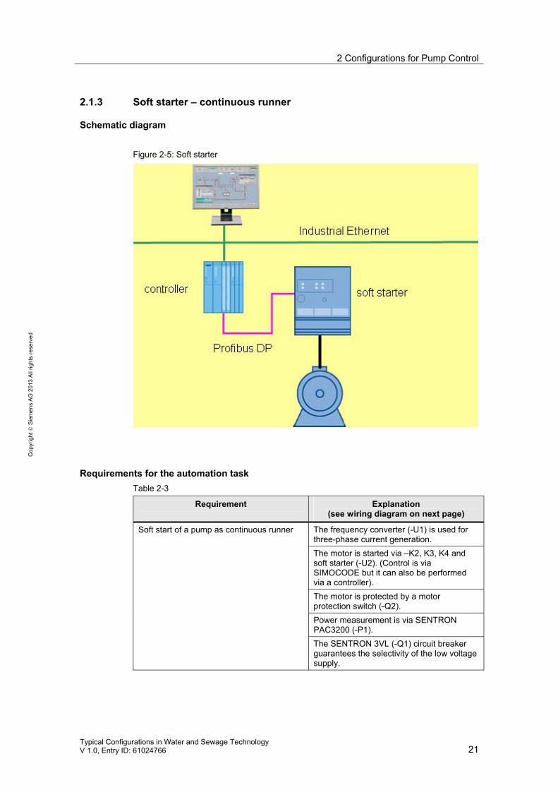
2.1.3 Soft starter – continuous runner
Schematic diagram Figure 2-5: Soft starter
Requirements for the automation task Table 2-3
Requirement Explanation (see wiring diagram on next page)
The frequency converter (-U1) is used for three-phase current generation. The motor is started via –K2, K3, K4 and soft starter (-U2). (Control is via SIMOCODE but it can also be performed via a controller). The motor is protected by a motor protection switch (-Q2). Power measurement is via SENTRON PAC3200 (-P1).
Soft start of a pump as continuous runner
The SENTRON 3VL (-Q1) circuit breaker guarantees the selectivity of the low voltage supply.

2 Configurations for Pump Control
22 Typical Configurations in Water and Sewage Technology
V 1.0, Entry ID: 61024766
Cop
yrig
ht ©
Sie
men
s A
G 2
013
All
right
s re
serv
ed
Wiring diagram Figure 2-6
2 Configurations for Pump Control
Typical Configurations in Water and Sewage Technology V 1.0, Entry ID: 61024766 23
Cop
yrig
ht ©
Sie
men
s A
G 2
013
All
right
s re
serv
ed
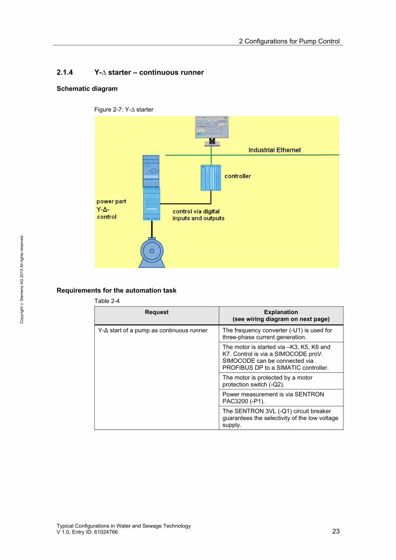
2.1.4 Y-∆ starter – continuous runner
Schematic diagram Figure 2-7: Y-∆ starter
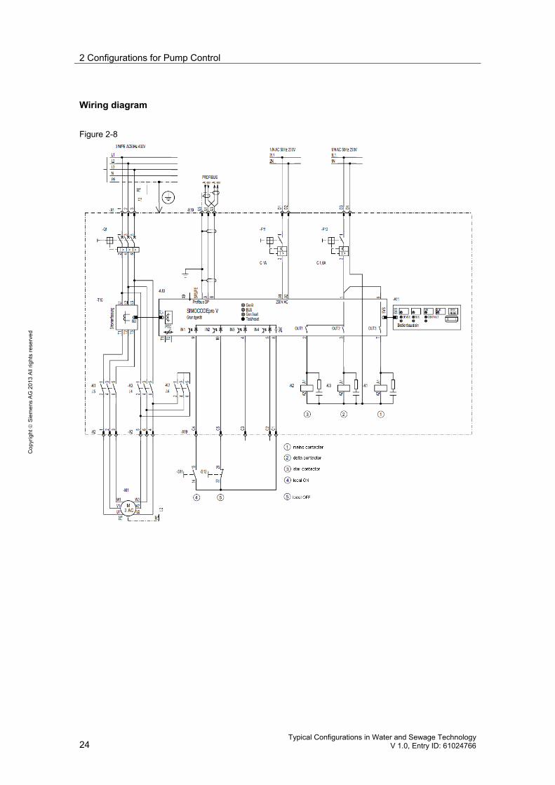
Requirements for the automation task Table 2-4
Request Explanation (see wiring diagram on next page)
The frequency converter (-U1) is used for three-phase current generation. The motor is started via –K3, K5, K6 and K7. Control is via a SIMOCODE proV. SIMOCODE can be connected via PROFIBUS DP to a SIMATIC controller. The motor is protected by a motor protection switch (-Q2). Power measurement is via SENTRON PAC3200 (-P1).
Y-Δ start of a pump as continuous runner
The SENTRON 3VL (-Q1) circuit breaker guarantees the selectivity of the low voltage supply.
2 Configurations for Pump Control
24 Typical Configurations in Water and Sewage Technology
V 1.0, Entry ID: 61024766
Cop
yrig
ht ©
Sie
men
s A
G 2
013
All
right
s re
serv
ed
Wiring diagram
Figure 2-8

3 Configuration of a Hydrostatic Level Measurement in a Steel Container
Typical Configurations in Water and Sewage Technology V 1.0, Entry ID: 61024766 25
Cop
yrig
ht ©
Sie
men
s A
G 2
013
All
right
s re
serv
ed
3 Configuration of a Hydrostatic Level Measurement in a Steel Container The level measurement is used to acquire the filling level of liquids and bulk material in a container.
3.1 Hydrostatic level display
For the hydrostatic filling level measurement in open containers, the hydrostatic pressure which is generated by the height of the liquid, is used to supply the measurement. The pressure measured is therefore a direct measure for the filling level and the height of the liquid above the sensor.
Overview of the plant configuration Figure 3-1: Overview
Requirements • level measurement with a maximum depth of 160 meters • signal transmission with PROFIBUS (fieldbus) • local height level display irrespective of fieldbus communication

3 Configuration of a Hydrostatic Level Measurement in a Steel Container
26 Typical Configurations in Water and Sewage Technology
V 1.0, Entry ID: 61024766
Cop
yrig
ht ©
Sie
men
s A
G 2
013
All
right
s re
serv
ed
3.2 Structure of the level display
Schematic diagram Figure 3-2: Set up of the solution
Advantages of the set up • measurement with separate power supply • local display functional even for inactive fieldbus
3 Configuration of a Hydrostatic Level Measurement in a Steel Container
Typical Configurations in Water and Sewage Technology V 1.0, Entry ID: 61024766 27
Cop
yrig
ht ©
Sie
men
s A
G 2
013
All
right
s re
serv
ed
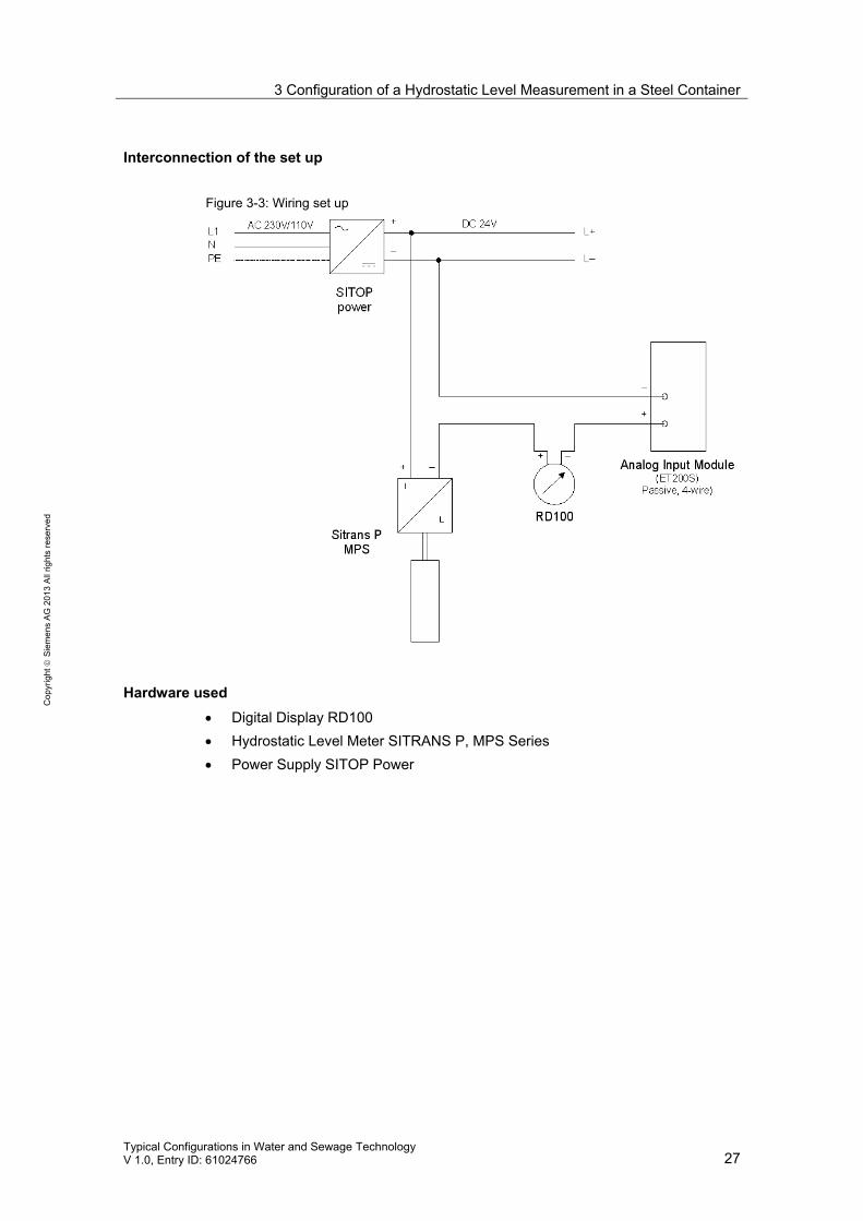
Interconnection of the set up Figure 3-3: Wiring set up
Hardware used • Digital Display RD100 • Hydrostatic Level Meter SITRANS P, MPS Series • Power Supply SITOP Power

4 Configuration of the Hach-Lange SC1000 Process Computer
28 Typical Configurations in Water and Sewage Technology
V 1.0, Entry ID: 61024766
Cop
yrig
ht ©
Sie
men
s A
G 2
013
All
right
s re
serv
ed
4 Configuration of the Hach-Lange SC1000 Process Computer
4.1 Process computer in the SIMATIC PCS 7 control system
The Hach-Lange SC1000 process computer is to be integrated in a SIMATIC automation solution (SIMATIC PCS 7).
Overview of the plant configuration
Figure 4-1: Configuration
Requirement The PLC shall be provided with the process values of the process computer for further processing. The process values from the process computer are to be transmitted from the PLC. The controller and control of the entire plant is performed via PLC.

4 Configuration of the Hach-Lange SC1000 Process Computer
Typical Configurations in Water and Sewage Technology V 1.0, Entry ID: 61024766 29
Cop
yrig
ht ©
Sie
men
s A
G 2
013
All
right
s re
serv
ed
4.2 Configuration of the control system with the process computer
Automation solution The Hach-Lange process computer calculates and evaluates the process model. The setpoints or process values required are exchanged via cross-data communication between the process computer and the AS 416-3 via Industrial Ethernet. Process authority lies with the AS 416-3 and the SIMATIC PCS 7 process control system. This means that the HL SC1000 has the job of a measuring transmitter for the acquisition and passing on of analysis measurements via PROFIBUS DP to the SIMATIC AS 416-3, despite its micro-controller functions. All required functions of the BIOLOGIE plant configuration, such as, for example, the switching on/off of fan motors, pressure measurements etc. are executed by the SIMATIC AS 416.3. In this concept, the process computer by HL is intended for the operation and monitoring. Remote access from the control room via ES or OS client to the HL process computer is possible via TCP/IP, VCN, NetMeeting or Remote Desktop.
Schematic diagram
Figure 4-2
5 Links & Literature
30 Typical Configurations in Water and Sewage Technology
V 1.0, Entry ID: 61024766
Cop
yrig
ht ©
Sie
men
s A
G 2
013
All
right
s re
serv
ed
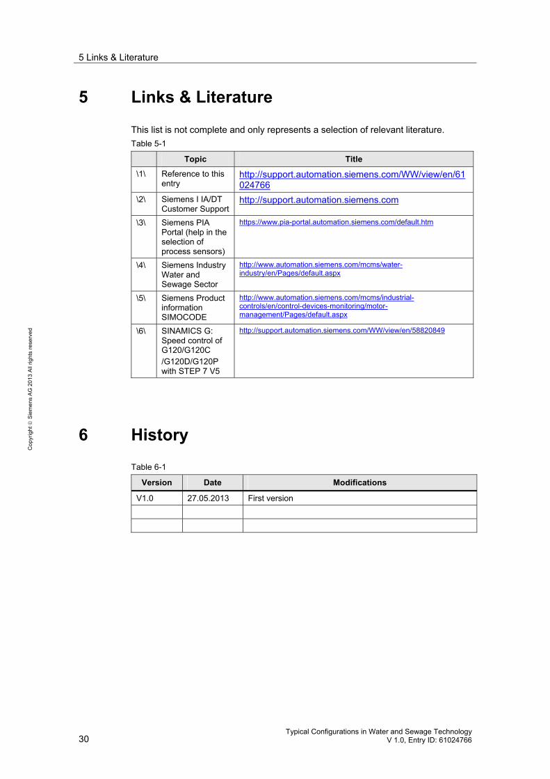
5 Links & Literature This list is not complete and only represents a selection of relevant literature. Table 5-1
Topic Title
\1\ Reference to this entry
http://support.automation.siemens.com/WW/view/en/61024766
\2\ Siemens I IA/DT Customer Support
http://support.automation.siemens.com
\3\ Siemens PIA Portal (help in the selection of process sensors)
https://www.pia-portal.automation.siemens.com/default.htm
\4\ Siemens Industry Water and Sewage Sector
http://www.automation.siemens.com/mcms/water-industry/en/Pages/default.aspx
\5\ Siemens Product information SIMOCODE
http://www.automation.siemens.com/mcms/industrial-controls/en/control-devices-monitoring/motor-management/Pages/default.aspx
\6\ SINAMICS G: Speed control of G120/G120C /G120D/G120P with STEP 7 V5
http://support.automation.siemens.com/WW/view/en/58820849
6 History Table 6-1
Version Date Modifications
V1.0 27.05.2013 First version